

Page 1

cover.frm Black I
DAS-800 Series
User’s Guide
Page 2

titlepgfrm Black 1
DAS-800 Series
User’s Guide
Revision A - December 1993
Part Number: 85790
Page 3

noticep.frm Black I
The information contained in this manual is believed to be accurate and reliable. However, the
manufacturer assumes no responsibility for its use; nor for any infringements or patents or other rights
of third parties that may result from its use. No license is granted by implication or otherwise under any
patent rights of the manufacturer.
THE MANUFACTURER SHALL NOT BE LIABLE FOR ANY SPECIAL, INCIDENTAL, OR
CONSEQUENTIAL DAMAGES RELATED TO THE USE OF THIS PRODUCT. THIS PRODUCT
IS NOT DESIGNED WITH COMPONENTS OF A LEVEL OF RELIABILITY THAT IS SUITED
FOR USE IN LIFE SUPPORT OR CRITICAL APPLICATIONS.
All brand and product names are trademarks or registered trademarks of their respective companies,
0 Copyright Keithley Instruments, Inc., 1993.
All rights reserved. Reproduction or adaptation of any part of this documentation beyond that permitted
by Section 117 of the 1976 United States Copyright Act without permission of the Copyright owner is
unlawful.
+b
Page 4
800ug.toc Black iii
+b
Table of Contents
Preface
1 Overview
Supporting Software . . . . . . . . . . . . .
Accessories
2 Functional Description
Analog Input Features ..............
Channel Configuration ...........
Input Configuration ...........
Gains and Ranges. ............
Channel Selection ............
Channel Expansion ...........
Conversion Clock Sources ........
Triggers. ......................
Gates .........................
Data Transfer. ..................
Digital I/O Features ................
8254 Counternimer Circuity ........
Interrupts ........................
Power ...........................
........
........
.......
.......
.......
.......
.......
.......
.......
.......
.......
.......
.......
.......
.......
.......
. . . . l-2
. . . . 1-4
. ...2-2
. ...2-3
. ...2-3
. . . .2-4
. ...2-5
. ...2-6
. ...2-8
. ..2-12
. ..2-14
. ..2-16
. ..2-17
. ..2-17
. ..2-25
. ..2-26
3 Setup and Installation
Installing the Software. ...............................
Installing the DAS-800 Series Standard Software Package . .3-5
Installing the ASO- Software Package
DOS Installation. ...............................
Windows Installation ............................
Unpacking the Board. ................................
Configuring the Board. ...............................
Creating a Configuration File.
Setting the Base Address ...........................
Setting the Input Contiguration ......................
Setting the Interrupt Level .........................
Installing the Board .................................
.3-4
.............. .3-6
.3-6
.3-7
.3-8
.3-8
....................... .3-9
.3-13
.3-16
.3-17
.3-19
iii
Page 5

800ug.toc Black iv
4
Cabling and Wiring
Attaching Accessory and Expansion Boards.
Attaching an STC-37 Screw Terminal Connector
Attaching an STA-08 / STA-OSPGA Screw Terminal
Accessory. .....................................
Attaching an EXP-16 or EXP-16/A Expansion Board.
Attaching an EXP-GP Expansion Board
Attaching an MB Series Backplane ...................
Connecting Multiple Expansion Boards.
Connecting Signals ..................................
Connecting an Analog Input Signal to a Single-Ended Input. 4-9
Connecting an Analog Input Signal to a Differential Input .4-10
Connecting Digital Signals, ........................
Connecting Counter/Timer I/O Signals
Synchronizing Conversions on Multiple Boards
5
The Control Panel
..............
........ .4-3
...............
...............
...............
........ .4-13
.4-l
.4-4
.... .4-5
.4-6
.4-7
.4-7
.4-9
.4-12
.4-12
6 Calibration
Equipment Required
Potentiometers
Calibration Utility
7
Troubleshooting
Problem Isolation
Troubleshooting Table.
Technical Support
A
Specifications
B
Connector Pin Assignments
............................
.................................
..............................
...............................
..........................
..............................
c DAS-800 Series External Driver
Running the DAS-800 Series External Driver. . . . . . .
Accessing the DAS-800 Series External Driver
Special Characteristics.. . . . . . . . . . . . .
Pseudo-Digital Output: Extended Functions. . . . .
Analog Triggers
Data Formats . . . . . . . . . . . . .
Using Expansion
Board
Gains . . . .
.,6-l
.6-2
.6-4
.,7-l
. . l-2
. l-4
.c-2
.c-2
.c-3
. .c-3
.C-6
.c-9
.c-11
iv
Page 6
800ug.toc Black v
Software Interrupt Vectors ......................
Counter/Iimer Functions .......................
Error Messages. .................................
II
Keithley Memory Manager
Installing and Setting Up the KMM.
Using
KMMSETUP.EXE
Using a Text Editor.
.......................
...........................
.................
Removing the KMM .............................
Index
List of Figures
Figure 2-l. DAS-800 Series Functional Block Diagram
Figure 2-2. Channel Expansion
...................
Figure 2-3. Initiating Conversions .................
Figure 2-4. Initiating Conversions with a Hardware
Trigger
Figure 2-5. Hardware Gate.
.............................
......................
Figure 2-6. Pulse on Terminal Count Mode. .........
Figure 2-7. Programmable One-Shot Mode. .........
Figure 2-8. Rate Generator Mode.
.................
Figure 2-9. Square-Wave Generator Mode ..........
Figure 2- 10. Software-Triggered Strobe Mode ........
Figure 2-l 1
Figure 3-l.
Figure 3-2.
Figure 3-3.
Figure 3-4.
Figure 3-5.
Figure 4-l.
Figure 4-2.
Hardware-Triggered Strobe Mode. .......... .2-24
DAS-800 Board. ......................... .3-2
DAS-Sol/802 Board ...................... .3-3
Setting the Base Address. ................. .3-14
Setting the Input Configuration. ............ .3-17
Setting the Interrupt Level. ................ ,3-18
Main I/O Connector on a DAS-800 Board ..... .4-2
Main I/O Connector on a DAS-801 or
DAS-802 Board. ......................... .4-3
Figure 4-3.
Attaching an STC-37 Screw Terminal
Connector. .............................. .4-4
Figure 4-4.
Attaching an STA-08 / STA-OSPGA Screw
Terminal Accessory. ...................... .4-5
Figure 4-5.
Attaching an EXP-16 or EXP-16/A Expansion
Board .................................. .4-6
Figure 4-6.
Figure 4-7.
Attaching an EXP-GP Expansion Board. ...... .4-7
Connecting Multiple Expansion Boards ....... .4-8
.c-12
.c-12
.c-13
. D-2
D-2
. D-3
D-4
. .2-2
. .2-l
.2-10
.2-13
.2-15
,2-19
.2-20
.2-21
.2-22
.2-23
Page 7
800ug.toc Black vi
Figure 4-8.
Figure 4-9.
Single-Ended Input , . . . . . . . . . . . . .4-10
Differential Input. . . . . . . . . . . .4-l 1
Figure 4-10. Synchronizing Conversions on Multiple
Boards . . . . . . , . . . . . . . . . . . . .4-13
Figure 4-l 1.
Figure 6-l.
Figure 6-2.
Figure B-l.
Figure B-2.
Figure C-l.
Figure C-2.
Figure C-3.
List of Tables
Table 2-1.
Table 2-2.
Table 2-3.
Dividing the Rate of the Master Clock .4-14
Potentiometers (DAS-800) . . . . . . . . . .6-3
Potentiometers (DAS-801 / DAS-802) . .6-3
Main I/O Connector (DAS-800) . . . . .B-2
Main I/O Connector @AS-801 / DAS-802) . . .B-5
Analog Trigger Conditions . . .C-7
Using a Hysteresis Value. . , . . . . . .C-8
Initiating Conversions with an Analog Trigger. . .C-9
Supported Gains .........................
Sources for 8254 Documentation
...........
Expansion Board / Backplane Power
Limitations .............................
Table 3-1.
Table 3-2.
Table 3-3.
Table 7-1.
Table A- 1.
Default Configuration
I/O Address Map (OOOH to 3FFH)
....................
..........
Interrupt Levels .........................
Troubleshooting Information.
...............
DAS-800, DAS-801, and DA.%802
Specifications. ...........................
Table B-l.
Main I/O Connector Pm Assignments for the
DAS-SOO................................B- 3
Table B-2.
Table C- 1.
Table C-2.
Table C-3.
Main I/O Connector Pin Assignments for the
DAS-801 /DAS-802
Pseudo-Digital Output Channels
......................
.............
Interrupt Vectors ........................
Error/Status Codes
.......................
.2-4
.2-25
.2-27
.3-10
.3-14
.3-18
.7-2
A- 1
.B-6
.C-4
.C-12
.C-13
vi
Page 8
preface.frm Black vii
f@
Preface
The DAM00 Series User’s Guide provides the information needed to set
up, install, and use DAS-800 Series boards.
The manual is intended for data acquisition system designers, engineers,
technicians, scientists, and other users responsible for setting up, cabling,
and wiring signals to DA,%800 Series boards. It is assumed that users are
familiar with
application.
data
acquisition principles and with their particular
The
DAS-BOO Series
Chapter 1 provides an overview of the features of DA%800 Series
boards, including a description of supported software and accessories.
Chapter 2 provides a more detailed description of the analog input,
digital I/O, and counter/timer I/O features of DAS-800 Series boards.
Chapter 3 describes how to unpack, configure, and install DAS-800
Series boards.
Chapter 4 describes how to attach accessory and expansion boards
and how to wire signals to DAS-800 Series boards.
Chapter 5 describes how to use the Control Panel to test the functions
of DAS-800 Series boards.
Chapter 6 describes how to calibrate DAS-800 Series boards.
Chapter 7 provides troubleshooting information.
Appendix A lists the specifications for DAS-800 Series boards.
User’s Guide is organized as follows:
vii
Page 9
preface.frm Black viii
. Appendix B lists the connector pin assignments.
. Appendix C describes how to use the DAS-800 Series External
Driver. The DAS-800 Series External Driver allows you to use
DAS-800 Series boards with certain data acquisition and analysis
software packages.
. Appendix D describes the Keithley Memory Manager. The Keithley
Memory Manager allows you to allocate sufficient memory when
running under Windowsm.
An index completes this manual.
Throughout the manual, keep the following in mind:
. References to DAS-800 Series boards apply to the DAS-800,
DAS-801, and DAS-802 boards. When a feature applies to a
particular board, that board’s name is used.
. References to Microsoft@ QuickBasic” apply to both Microsoft
QuickBASIC (Version 4.0) and Microsoft QuickBasic (Version 4.5).
Page 10

chapOl_.frm Black 1
Overview
The DAS-800 Series is a family of analog input and digital input and
output (I/O) boards for an IBM@ PC/XTTM, AT’ or compatible computer.
The DAS-80 Series includes the DAS-800, DAS-801, and DAS-802
boards, The major features of DAS-800 Series boards are as follows:
Eight analog input channels (single-ended on the DAS-800;
single-ended or differential on the DAS-801 and DAS-802).
Fixed f5 V analog input range for the DAS-800; nine unipolar and
bipolar, software-selectable analog input ranges for the DAS-801 and
DAS-802.
On-board 8254 counter/timer circuitry, which you can use as a
hardware internal clock source and/or for general-purpose
counter/timer I/O operations.
Software-selectable conversion clock source.
Digital trigger.
Hardware gate.
Four-word FIFO to store converted data: overrun detection logic to
detect lost dam points.
Software-selectable interrupt source.
Three bits of digital input.
. Four bits of digital output.
l-1
Page 11
chapOl_.frm Black 2
Note:
DAS-800 boards are enhancements of DAS-8 boards; DAS-801
boards are enhancements of DAS-8 PGA boards; DAS-802 boards are
enhancements of DAS-8 PGA/G2 boards. You can use application
programs written to support the DAS-8 with the DAS-800, application
programs written to support the DAS-8 PGA with the DAS-801, and
application programs written to support the DAS-8 PGA/GZ with the
DAS-802.
Supporting Software
You can use DAS-800 Series boards with the following software:
DASJOO Series standard software package
DAS-800 Series boards. Includes function libraries for writing
application programs under DOS in a high-level
Microsoft QuickBasic and Microsoft Visual BasicTM for DOS, support
files, utility programs, and language-specific example programs.
Refer to
more information.
the DAM00 Series Function Call Driver User’s Guide
- Shipped with
language
such as
for
l-2
ASO-
software package - The optional Advanced Software
Option for DAS-800 Series boards. Includes function libraries for
writing application programs under Windows and DOS in a
high-level language such as Borland@ C/C++, Borland Turbo Pascal@
for DOS and Windows, and Microsoft Visual Basic for Windows;
support files; utility programs; and language-specific example
programs. Refer to the
Guide
for more information.
DA&800 Series utilities
DA&BOO Series Function Cull Driver User’s
- The following utilities are provided as part
of both the DAS-800 Series standard software package and the
ASO- software package:
-
Confgurarion urilify
-The configuration utility (D800CFG.EXE)
allows you to create or modify a configuration tile. The
configuration tile indicates the settings of switches and jumpers
on the board and provides other configuration information. This
information is used by the DAS-800 Series Function Call Driver
and other software packages to perform the board’s I/O
Overview
Page 12

chapOl_.frm Black 3
operations. Refer to page 3-9 for more information about the
configuration utility.
-
Control Panel
-The Control Panel allows you to perform
operations on DAS-800 Series boards, without programming. It
provides a quick way to test your board and monitor
your I/O
operation. Two versions of the Control Panel are available:
CTL800.EXE (for DOS) and CTLBOOW.EXE (for Windows).
Refer to Chapter 5 for more information about the Control Panel.
-
Calibrafion uriliry
- The calibration utility (CALSOO.EXE) allows
you to calibrate the analog input circuitry of DAS-800 Series
boards. Refer to Chapter 6 for more information about the
calibration utility.
. DAM300 Series custom controls
programs in Visual Basic for Windows. Refer to the
Custom
. Data acquisition and analysis application software -
Controls User’s Guide
- Help you to write application
VisualDAS
for more information.
Many
menu-driven, integrated software packages are available for
DAS-800 Series boards, including VIEWDAC?, EASYEST LXa’,
and EASYEST AGW. In addition, programming tools, such as the
ASYST@ scientific and engineering programming
language, are
available to help you customize your own application program.
Note:
If you use VIBWDAC!, EASYEST LX / AG, or ASYST to
program your DAS-800 Series board, you must use the DA&800
Series External Driver, which is shipped as part of the DAS-800
Series standard software package. Refer to Appendix C for
information on using the DAS-800 Series External Driver.
. DAS-800 Series register I/O map - If you cannot satisfy your
application’s requirements with the available software packages and
you are an experienced programmer, you may be able to program
your DAS-800 Series
board
through direct register I/O instructions.
Contact the factory for more information.
I-3
Page 13

chapOl_.frm
Accessories
Black 4
The following accessories are available for use with DAS-800 Series
boards:
. STC-37 screw terminal connector - For
all DAS-800 Series boards,
provides 37 screw terminals that allow you to access the functions of
the board; connects directly to the DAS-800 Series board without a
cable.
l
STA-08 screw terminal accessory - For the DAS-800 board
provides screw terminals that allow you to access the functions of the
board; provides a breadboard area with power and additional screw
terminals to access the user-designed circuitry.
. STA-08PGA screw terminal accessory
- For the DAS-801 and
DAS-802 boards only, provides screw terminals that allow you to
access the functions of the
board;
provides a breadboard area with
power and additional screw terminals to access the user-designed
circuitry.
. EXP-16 and EXP-16/A expansion boards
- Sixteen-channel
multiplexer and signal-conditioning expansion boards; provide cold
junction compensation (CJC) for thermocouples and
switch-selectable gains ranging from 0.5 to 2000.
. EXP-GP expansion board
- An 8-channel signal-conditioning
expansion board; connects to RTDs, thermistors, strain gages, and
other variable resistance sensors; provides CJC for thermocouples
and switch-selectable gains of 1, 10, 100, and 1000 or 2.5.25.250,
and 2500.
only,
1-4
. MB Series modules and backplanes
- MB Series modules are
high-performance, signal-conditioning modules that measure
thermocouple, RTD, strain gage, voltage, and current inputs and are
installed in MB Series backplanes. MB Series backplanes provide
screw terminals for connecting the high-level analog I/O signals.
Overview
Page 14
chapOl_.frm Black 5
. STA-SCM8
screw terminal accessory - Allows you to
connect a
DAS-800 Series board to up to four MB-02 backplanes; provides
screw terminals that allow you to access the functions of the board;
provides a breadboard area with power for the user-designed circuitry.
. C-1800 cable
-Unshielded, la-inch cable with a 37-pin connector on
each end: allows you to connect a DAS-800 Series board to an
STA-08, STA-08PGA, EXP-16, EXP-16/A, or EXP-GP.
. S-1800 cable - Shielded, la-inch cable with a 37-pin connector on
each end; allows you to connect a DAS-800 Series board to an
STA-08, STA-OBPGA, EXP-16, EXP-16/A, or EXP-GP.
. CB-MB1
cable
- Cable with a 37-pin connector on one end and a
26-pin-connector on the other end; allows you to connect a DAS-800
Series board to an MB-01 or MB-02 backplane.
. C-2600 cable
- An la-inch cable with a26-pin connector at each end;
allows you to connect an STA-SCM8 screw terminal accessory to an
MB-02 backplane.
l-5
Page 15

chapOl_.frm Black 6
Page 16
chap02Lfrm Black 1
4
2
Functional Description
This chapter describes the following features of DAS-800 Series boards:
. Analog input features
. Digital I/O features
. Counter/timer I/O features
4
l
Interrupts
. Power
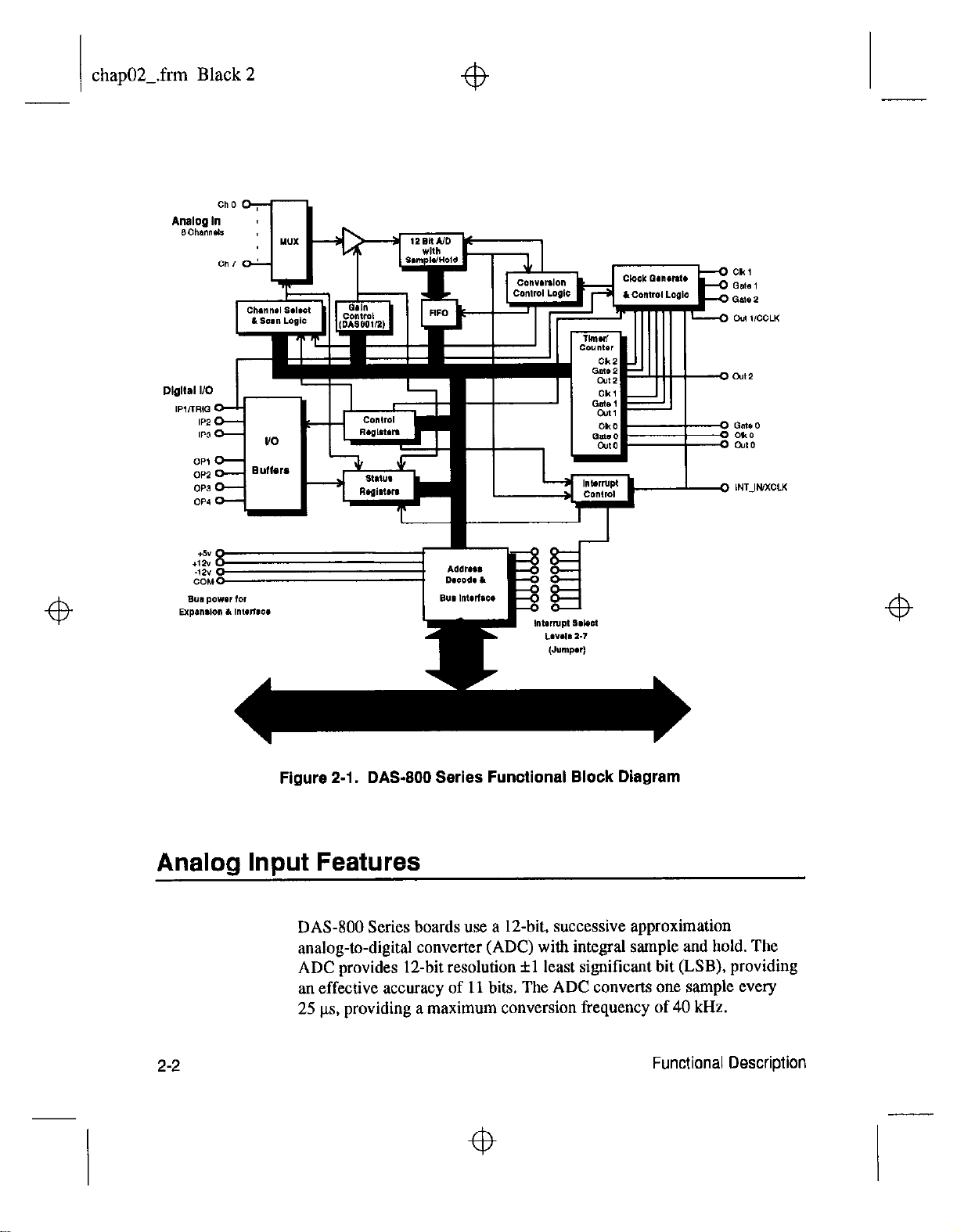
A functional block diagram of a DAS-800 Series board is shown in
Figure 2- 1.
4
2-l
Page 17
chap02-.frm Black 2
4
4
Figure 2-1. DAS-800 Series Functional Block Diagram
Analog Input Features
DAS-800 Series boards use a 12-bit, successive approximation
analog-to-digital converter (ADC) with integral sample and hold. The
ADC provides 1Zbit resolution fl least significant bit (LSB), providing
an effective accuracy of 11 bits. The ADC converts one sample every
25 ks, providing a maximum conversion frequency of 40 kHz.
2-2
4
Functional Description
4
Page 18
chap02-.frm Black 3
Channel Configuration
DAS-800 Series boards contain eight on-board analog input channels.
The following subsections describe the input configurations supported for
each channel, the gains
the methods of specifying a channel or channels for an analog input
operation.
On the DA%801 and DAS-802, you can configure each channel as either
single-ended or differential. The differences between a single-ended and a
differential input configuration are described as follows:
and
input ranges supported for each channel, and
4
. Single-ended
you are measuring relatively high-level signals (greater than 1 V), if
the source of the input signal is close to the board (less than two feet),
or if all input signals are referred to a common ground. This
configuration does not provide common-mode noise rejection.
. Differential
are measuring low-level signals, if high source resistances (greater
than 100 D) exist, or if common-mode voltages exist between the
voltage source and the host’s chassis ground. In a differential
configuration, a separate positive and negative terminal is provided
for each channel. Any common-mode noise that is picked up equally
on both inputs is rejected because the difference is zero.
You specify the input configuration by setting switches on the board. The
switches connect or disconnect the inverting side of the input signal to
low-level ground. Refer to page 3-16 for information on setting the
switches.
Notes: On the DAS-800, the
single-ended; ah signals are referred to a single low-level ground.
- A single-ended input configuration is appropriate if
- A differential input configuration is appropriate if you
channels are always configured as
4
If you are using BXP-16, EXP-16/A, or EXP-GP expansion
MB-02 backplanes, you must configure the on-board analog input
channels associated with the expansion boards or backplanes as
single-ended.
boards or
4
2-3
Page 19
chap02Lfrm Black 4
Gains and Ranges
4
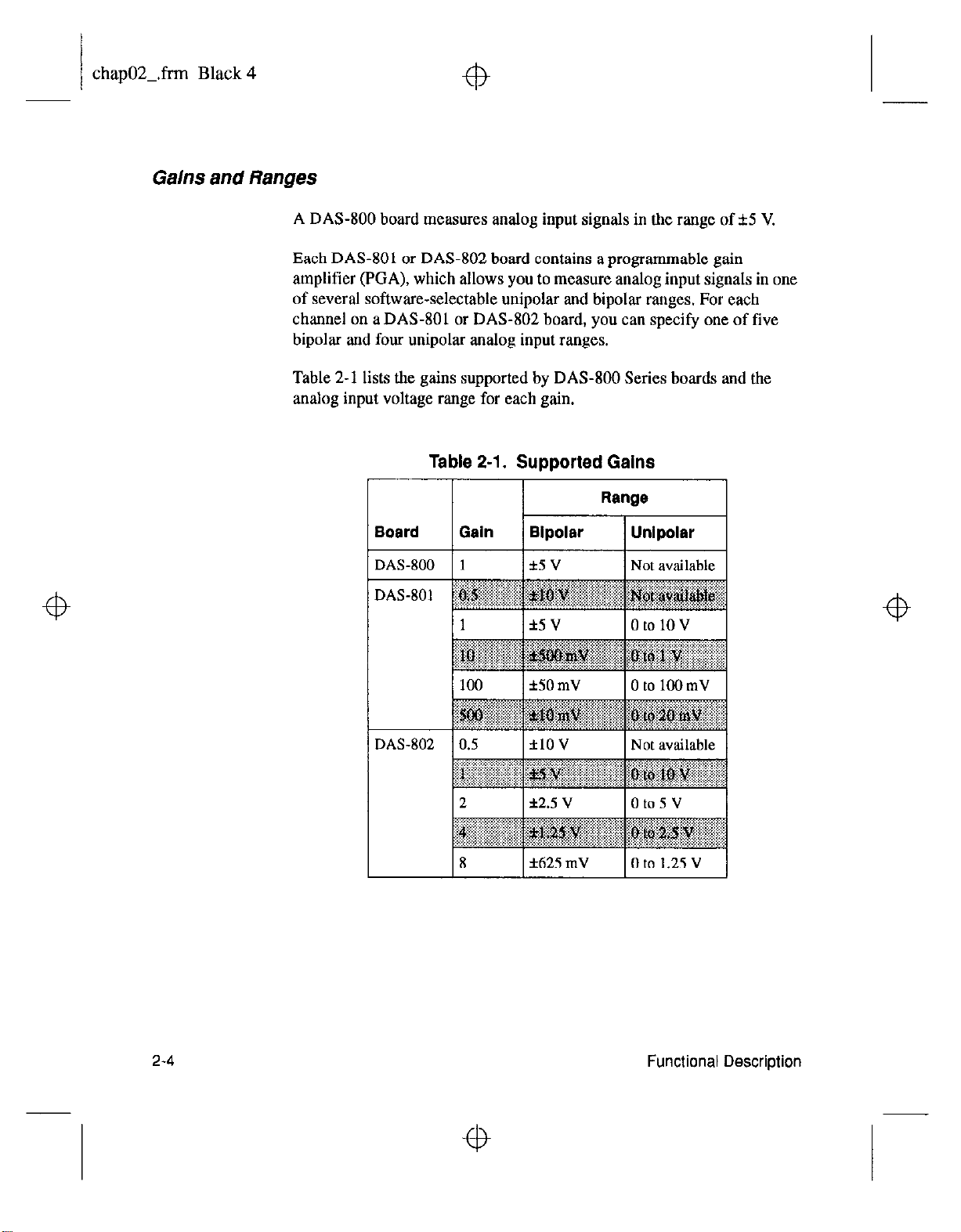
A DAS-800 board measures analog input signals in the range of f5 V.
Each DAS-801 or DAS-802 board contains a programmable gain
amplifier (EGA), which allows you to measure analog input signals in one
of several software-selectable unipolar and bipolar ranges. For each
channel on a DAS-801 or DAS-802 board, you can specify one of five
bipolar and four unipolar analog input ranges.
Table 2-1 lists the gains supported by DAS-800 Series boards and the
analog input voltage range for each gain.
Table 2-l. Supported Gains
2-4
4
Functional Description
4
Page 20

chap02-.frm Black 5
4
4
Note:
with protection against signals outside the specified analog input range.
All DAS-800 Series boards can tolerate voltages up to f35 V and
transients of several hundred volts without damaging the board.
When measuring signals at differential inputs, DAS-801 and DAS-802
boards can tolerate common-mode voltages up to f35 V and transients of
several hundred volts without damaging the board; however, for normal
operation of the board, make sure that the common-mode voltage is no
more than 12 V - ((C / 2) x
differential input voltage.
Channel Selection
You can use DAS-800 Series boards to acquire data from a single analog
input channel or from a range of contiguous, on-board analog input
channels using automatic channel scanning. These two methods of
channel selection are described as follows:
.
Analog input channels on DAS-800 Series boards are provided
V,),
Single
initiate a conversion.
channel - You use software to specify a single channel and
where G is tbe gain and
V,
is the
4
. Automatic channel scanning
and last channels in a range of contiguous, on-board channels (0 to 7).
The channels are sampled in order from first to last; the hardware
automatically increments the analog input multiplexer address shortly
after the start of each conversion. When the last address is reached,
the multiplexer returns to the start address and the channels are
sampled again. For example, assume that the start channel is 4, the
stop channel is 7, and you want to acquire five samples. Your
program reads data first from channel 4, then from channels 5, 6, and
7, and finally from channel 4 again.
The start channel can be higher than the stop channel. For example,
assume that the start channel is 7, the stop channel is 2, and you want
to acquire five samples. Your program reads data first from channel 7,
then from channels 0, 1, and 2, and finally from channel 7 again.
When using automatic channel scanning, all contiguous, on-board
channels must have the same gain (analog input range).
- You use software to specify the first
2-5
4
Page 21

chap02Lfrm Black 6
fb
Note:
that includes channels on expansion boards or MB Series backplanes,
you can create a group of consecutive channels through software. tn
addition, if your application requires non-consecutive channels or
different gains for each channel, you can create a channel-gain list
through software. The DAS-800 Series Function Call Driver provides
functions for creating a group of consecutive channels or
channel-gain list; refer to the
User’s
you to set up a group of consecutive channels or channel-gain list;
refer to Chapter 5 for more information. You can also set up a group
of consecutive channels or channel-gain list using DAS-800 Series
custom controls; refer to
Guide
Automatic channel scanning is a hardware feature. The functions
used to create a group of consecutive channels or a channel-gain list
emulate automatic channel scanning through software. Therefore, the
maximum attainable conversion frequency is reduced when using a
group of consecutive channels or a channel-gain list.
Channel Expansion
If you want to acquire
Guide
for more information. The Control Panel also allows
the VisualDAS Custom Controls User’s
for more information.
data
from a range of multiple channels
DAM00 Series Function Call Driver
Z-6
If you require additional analog input channels or signal conditioning for
transducer inputs, you can use any combination of up to eight 16-channel
EXP-16 expansion boards, eight 16-channel EXP-16/A expansion boards,
and/or eight X-channel EXP-GP expansion boards to increase the number
of available channels to 128. You can also use up to four MB-02
backplanes to increase the number of available channels to 68.
For the EXP-16, EXP-16/A. and EXP-GP, you attach the expansion
boards in a daisy-chain configuration using the S-1800 or C-1800 cable.
The first expansion board in the daisy chain is associated with on-board
channel 0, the next expansion board is associated with
1, and so on. You specify the associated on-board channel by setting a
jumper on each expansion board. You can access any unused on-board
channels by attaching an STA-08 or STA-OBPGA screw terminal
accessory to the last expansion board in the daisy-chain configuration.
on-board
Functional Description
channel
Page 22
chapOZ.frm Black 7
fb
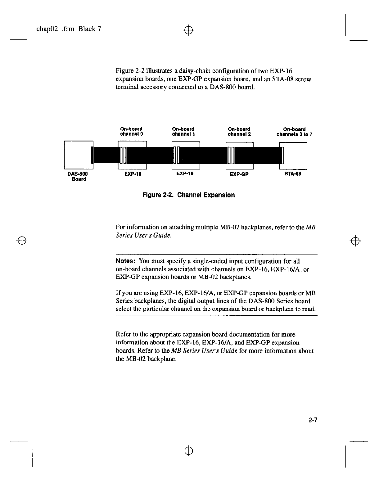
Figure 2-2 illustrates a daisy-chain configuration of two EXP-16
expansion boards, one EXP-GP expansion board, and an STA-08 screw
terminal accessory connected to a DAS-800 board.
Omboard
channel 0
I I I I r I I I
D&3-600
Board
EXP.16
Figure 2-2. Channel Expansion
On-board On-board
channel 1
EXP-16
channal2 chsnnsls 3 to 7
EXPQP
For information on attaching multiple MB-02 backplanes, refer to the ME
Series User’s Guide.
Notes:
You must specify a single-ended input configuration for all
on-board channels associated with channels on EXP-16, EXP-16/A. or
EXP-GP expansion boards or MB-02 backplanes.
If you are using EXP-16, EXP- 16/A, or EXP-GP expansion boards or MB
Series backplanes, the digital output lines of the DAS-800 Series board
select the particular channel on the expansion board or backplane to read.
On-board
STA.08
Refer to the appropriate expansion board documentation for more
information about the EXP-16, EXP-16/A, and EXP-GP expansion
boards. Refer
to the ME Series User’s Guide
for more information about
the MB-02 backplane.
2-7
Page 23
chap02-.frm Black 8
Conversion Clock Sources
4
The conversion clock source determines when each analog-to-digital
(A/D) conversion is initiated. DAS-800 Series boards provide the
following software-selectable conversion clock sources:
. Software -When using a software conversion clock, the host
computer issues a command to initiate a conversion. The host polls
the board to determine if the conversion is complete. When the
conversion is complete, the host reads the data from the ADC and
returns the value. If the host reads data before the conversion is
complete, the data will be invalid.
Software-initiated conversions are suitable for measuring DC
voltages; however, in applications where you must accurately control
the sampling rate (as when measuring time-varying signals), it is
recommended that you use either an internal or an external hardware
conversion clock source.
4
At power-up or system reset, the board assumes that conversions will
be initiated through software.
. Hardware (internal clock source) -The internal clock source uses
the on-board 8254 counter/timer circuitry and a crystal-controlled
I MHz time base. The 8254 counter/timer circuitry is normally in an
idle state. When you start an analog input operation, a conversion is
initiated immediately. The 8254 is loaded with its initial count value
and begins counting down. When the 8254 counts down to 0, another
conversion is initiated and the process repeats.
Because the 8254 counter/timer uses a 1 MHz time base, each count
represents 1 ps. For example, if you load a count of 25, the time
interval between conversions is 25 ps: if you load a count of 65536,
the time interval between conversions is 65.536 ms.
4
2-6
Functional Description
4
Page 24

chap02Lfrm Black 9
+b
The 8254 contains three counter/timers: C/TO, Cnl, and C/r2. If you
are using a hardware internal clock source, the time base logic uses
C/T1 and C/r2 in either normal or cascaded mode, as follows:
- Normal
of the 8254 counter/timer circuitry. Each time C/r2 reaches
terminal count, a conversion is initiated. The time interval
between conversions ranges from 25 FLS to 65.536 ms.
Cascaded Mode
C/r2 and C/r1 of the 8254 counter/timer circuitry. When CK2
counts down to 0, CR1 decrements by 1. Cn2 is reloaded with
its count value and begins counting down again. Each time C/r2
counts down to 0, Cm1 decrements by 1. Each time both C/r2
and CR1 reach terminal count, a conversion is initiated. The time
interval between conversions ranges from 25 ps to 1.2 hours.
Note:
system reset, the DA%800 board connects the clock input of C/r2 to
the CPU bus clock divided by two. If you specify a hardware internal
clock source through software, the DAS-800 board connects the clock
inputs of C/T1 and CD2 to the 1 MHz time base. The DAS-801 and
DAS-802 boards always connect the clock input of C/f2 to the
1 MHz time base.
Refer to page 2-17 for more information about the 8254 counter/timer
circuitry.
Mode
- A software-selectable count is loaded into C/r2
- A software-selectable count is divided between
For compatibility with the DAS-8 board, on power-up or
. Hardware (external clock source) - An external clock source is
useful if you want to sample at rates not available with the 8254
counter/timer circuitry, if you want to sample at uneven intervals, or if
you want to sample on the basis of an external event. An external
clock also allows you to synchronize conversions on multiple boards
to a common timing source.
2-9
Page 25

chap02-.frm Black 10
fb
The external clock source is an externally applied TTL-compatible
signal, which you attach to the INT-IN / XCLK pin (pin 24) of the
main I/O connector. When you start an analog input operation,
conversions are
soume (and at every subsequent falling edge of the external clock
source), a conversion is initiated.
armed.
At the next falling edge of the external clock
Note:
use the INT-IN / XCLK pin (pin 24) to generate interrupts.
Figure 2-3 illustrates how conversions are initiated when using an internal
and an external clock source. (Note that Figure 2-3 assumes that you are
not using a hardware trigger; refer to Figure 2-4 for an illustration of
conversions when using a hardware trigger.)
If you are using a hardware external clock source, you cannot
2-l 0
Figure 2-3. Initiating Conversions
Functional Description
Page 26
chap02Lfrm Black 11
Notes: The ADC acquires data at a maximum of 40 kHz (one sample
every 25 ns). If you are using a hardware external clock, make sure that
the clock does not initiate conversions at a faster rate than the ADC can
handle.
To achieve full measurement accuracy when using a gain of 500, you
should limit me conversion frequency to a maximum of 25 kHz (one
sample every 40 its).
If you are acquiring samples from multiple channels. the maximum
sampling rate for each channel is equal to 40 kHz divided by the number
of channels.
The rate at which the computer can reliably read data from the board
depends on a number of factors, including your computer, the operating
system/environment, whether you are using expansion boards, the gains
of the channels, and software issues.
You can synchronize conversions on multiple DAS-800 Series boards to a
common, externally applied conversion clock. In addition, you can use a
DAS-801 or DAS-802 board as a timing master; the output of the OUT1
pin (pin 5) on the main I/O connector of the master board acts as an
external hardware conversion clock to any additional boards. You can use
external circuitry, such as CEO on the 8254, to divide the rate of the
master clock; this allows you to synchronize conversions on the
additional hoards to a rate different from that of the master board. Refer to
page 4-13 for more information on synchronizing conversions on multiple
boards.
2-11
Page 27
chap02_.frm Black 12
Triggers
A trigger is an event that must occur before a DAS-800 Series board starts
an analog input operation. You can use one of the following trigger
sources to trigger aa analog input operation:
. Software - When you start the analog input operation, conversions
begin
immediately.
. Hardware - You connect a digital trigger signal to the digital input
IP 1 /TRIG pin (pin 25) of the main I/O connector. The trigger event
occurs when the board detects a rising edge on IP1 /TRIG.
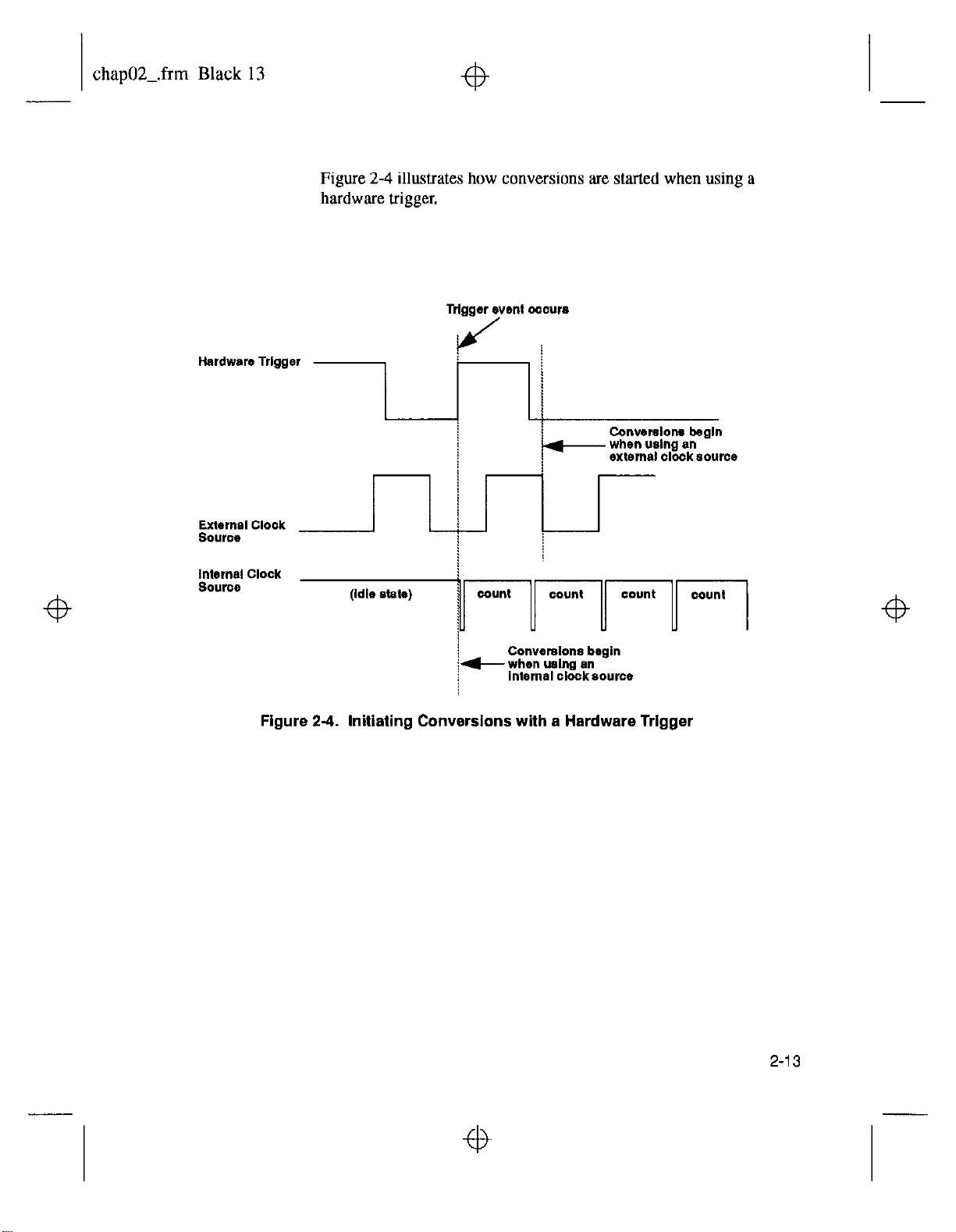
The actual point at which conversions begin depends on whether you
are using an internal or external clock soorce. These considerations
are described as follows:
-
Internal clock
source - The 8254 counter/timer circuitry remains
idle until the trigger event occurs. When the trigger event occurs,
the
board
initiates the first conversion immediately.
- Enrernal
clock
source - Conversions are armed when the trigger
event occurs. At the next falling edge of the external clock
source, the board initiates the first conversion.
2-12
Functional Description
Page 28
chap02-.frm Black 13
Figure 2-4 illustrates how conversions are started when using a
hardware trigger.
External Clock
source
Figure 24. Initiating Conversions
!
!
with
a Hardware Trigger
2-13
Page 29
chap02-.frm Black 14
Hardware Gates
A hardware gate is an externally applied digital signal that determines
whether conversions occur. You connect the gate signal to the IPl /TRIG
pin (pin 25) on the main I/O connector. DAS-800 Series boards support a
positive gate only. Therefore, if the hardware gate is enabled and the
signal to IPl /TRIG is high, conversions occur; if the signal to IPl /
TRIG is low. conversions are inhibited.
Note:
You cannot use the hardware gate with a hardware trigger.
However, the gate signal itself can act as a trigger. If the gate signal is low
when the software starts the analog input operation, the board waits until
the gate signal goes high before conversions begin.
When using the hardware gate, the way conversions are synchronized
depends on whether you are using a hardware external clock or a
hardware internal clock, as follows:
. External
clock
- The signal from the external clock continues
uninterrupted while the gate signal is low; therefore, conversions are
synchronized to the external clock.
. Internal clock - The 8254 does not count while the gate signal is low.
Whenever the gate signal goes high, the 8254 is loaded with its initial
count value and starts counting; therefore, conversions are
synchronized to the gate signal.
Figure 2-5 illustrates how to use the hardware gate with both an external
clock and an internal clock.
2-14
Functional Description
Page 30

chap02-.frtn Black 15
sonware starts
ths
operation -b
3rd convmsion
2nd conversion
/ /
p-r . . . . . . * . . . . .
at wnverslon ,
(Intcmsl clock)
Note:
analog trigger, you can program an analog trigger through software, using
one of the analog input channels as the trigger channel. The DAS-800
Series Function Call Driver provides functions for an analog trigger; refer
to
the DAS-800 Series Funciion Call Driver User’s Guide
information. The Control Panel also allows you to set up an analog
trigger; refer to Chapter 5 for more information. You can also set up an
analog trigger using DAS-800 Series custom controls; refer to the
VisualDAS
2nd mnvwston
(Inkmel clock)
Figure 2-5. Hardware Gate
t
3rd l2dverslon
(Internal clock)
4th converslbn
(Internalclock)
A-
Although DAS-800 Series boards do not provide a hardware-based
for more
Custom
Controls Lrser’x Guide
for more information.
2-I 5
Page 31
chapOZ.frm Black 16
Data Transfer
fb
Because DAS-800 Series boards do not support DMA (Direct Memory
Access), data is always transferred from a DAS-800 Series board to the
host computer’s memory through an output port. Data can be transferred
as either a foreground process or a background process. If data is
transferred in the background, the end-of-conversion interrupt must be
enabled so that the board can notify the host computer when new data is
available; refer to page 2-25 for more information about interrupts. If data
is transferred in the foreground, interrupts are not required.
DA%800 Series boards contain a four-word, first-in, first-out memory
location (FIFO). When you initiate conversions under hardware control,
using an internal or external clock source, the result of each conversion is
automatically stored in the FIFO.
Note:
logic is automatically disabled and the FIFO is emptied.
The FIFO increases the maximum attainable conversion frequency by
increasing the maximum software interrupt latency allowed by a factor of
four (up to the maximum conversion frequency of 40 kHz).
If the conversion frequency is too fast or if the time required to service the
interrupt is too long, the hardware may perform more than four
conversions before the converted data is read. The hardware can detect
this condition and generate an error to indicate that unread data in the
FIFO was overwritten and samples were lost.
Panel, or Custom Controls, the operation of the FIFO is transparent. The
Function Call Driver, Control Panel, or Custom Controls software
When you use software to initiate conversions, the FIFO control
Note:
performs the data transfer.
When using the DAS-800 Series Function Call Driver, Control
2-I 6
Functional Description
Page 32

chap02-.frm Black 17
Digital l/O Features
DAS-800 Series boards contain three digital input lines and four digital
output lines. The digital input lines are associated with the IPI /TRIG,
IP2, and IP3 pins on the main I/O connector; the digital output lines are
associated with the OPI. OP2. OP3. and OP4 pins on the main I/O
connector. Logic 1 at a pin indicates that the input/output is high (greater
than 2.0 V); logic 0 at a pin indicates that the input/output is low (less
than 0.8 V).
The digital input lines are compatible with TTL-level signals. If no signal
is connected to a digital input line, the input appears high (logic 1).
You can use the digital input and output lines for any general-purpose
task, with the following exceptions:
. If you are using an expansion board for an analog input operation, the
four digital output lines control the multiplexem on the expansion
boards to determine the expansion board channel that is acquiring
data; in this case, you cannot use the digital output lines for
general-purpose digital output operations.
. If you are using an external digital trigger or hardware gate, you must
use the IPI /TRIG pm to attach the trigger/gate signal: in this case,
you cannot use IPl /TRIG for general-purpose digital input
operations.
8254 Counter/Timer Circuitrv
Each DAS-800 Series board contains 8254 counter/timer circuitry; the
8254 contains three counter/timers: C/IO, Cnl, and W2.
C/IO is always available for general-purpose tasks. If you are using a
hardware internal clock source for an analog input operation, both C/T1
and C/T2 of the 8254 counter/timer circuitry are dedicated to internal
functions and cannot be used for general-purpose tasks. If you are using a
hardware external clock source, ClrO, C/Tl, and C/I’2 are always
available for general-purpose tasks.
2-17
Page 33
chap02-.frm Black 18
C/TO and C/T1 have a clock input pin on the main I/O connector; all
counter/timers have a gate input pin and an output pin on the main I/O
connector. You can attach a clock source (0 to 10 MHz) to the clock input
pins (CLKO and CLKl). Pull-up resistors of 3.3 ka are provided on the
three gate input pins (GATEO, GATEl, and GATE2); therefore, the gates
appear enabled if no signal is attached to the gate inputs. You can use the
output pins (OUTO, OUTl, and OUT2) for pulse or frequency outputs.
Notes: For compatibility with the DAS-8 board, on power-up or system
reset, the DAS-800 board connects the clock input of CF2 to the CPU
bus clock divided by two. If you specify a hardware internal clock source
through software, the DA%800 board connects the clock inputs of C/T1
and C/r2 to the 1 MHz time base. The DAS-801 and DAS-802 boards
always comect the clock input of Cn2 to the 1 MHz time base.
You can use the OUT1 pin of a DAS-801 or DAS-802 board to
synchronize conversions on multiple boards. Refer to page 4- 13 for more
information.
The CLKl, GATEl, and GATE2 pins are provided for compatibility with
DAS-8, DAS-8 PGA, and DAS-8 PGA/G2 boards on power-up or system
reset. If you specify a hardware internal clock source through software,
you cannot use these pins.
2-i 6
Functional Description
Page 34

chap02Lfrm Black 19
fb
You can program the 8254 counter/timer circuitry to operate in one of the
following counter/timer modes:
. Pulse on terminal count (Mode 0) - This mode is useful for event
counting or for programming a time delay. The software forces the
output low. On the next clock pulse after the software writes the
initial count value, the counter is loaded. When the counter reaches
zero, the output goes high and remains high until the software writes a
new count value. Note that the output does not go high until n + 1
clock pulses after the initial count is written, where n indicates the
loaded count.
A high gate input enables counting; a low gate input disables
counting. The gate input has no effect on the output. Note that an
initial count value written while the gate input is low is still loaded on
the next clock pulse.
Figure 2-6 illustrates pulse on terminal count mode.
clock pulse
softwar* tomes
output low --)
output
I
Figure 2-6. Pulse on Terminal Count Mode
3
2
1
2-19
Page 35
chapO2Lfrm Black 20
+b
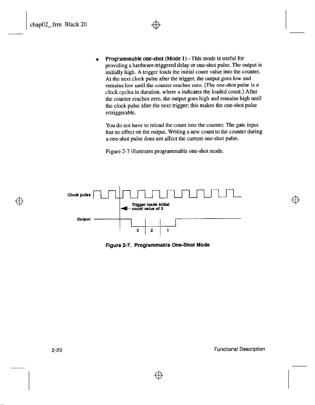
. Programmable one-shot (Mode 1) -This
mode is useful for
providing a hardware-triggered delay or one-shot pulse. The output is
initially high. A trigger loads the initial count value into the counter.
At the next clock pulse after the trigger, the output goes low and
remains low until the counter reaches zero. (The one-shot pulse is n
clock cycles in duration, where n indicates the loaded count.) After
the counter reaches zero, the output goes high and remains high until
the clock pulse after the next trigger; this makes the one-shot pulse
retriggerable.
You do not have to reload the count into the counter. The gate input
has no effect on the output. Writing a new count to the counter during
a one-shot pulse does not affect the current one-shot
pulse.
Figure 2-7 illustrates programmable one-shot mode.
Z-20
output
I
3 2 1
Figure 2-7. Programmable One-Shot Mode
Page 36
chap02Lfrm Black 21
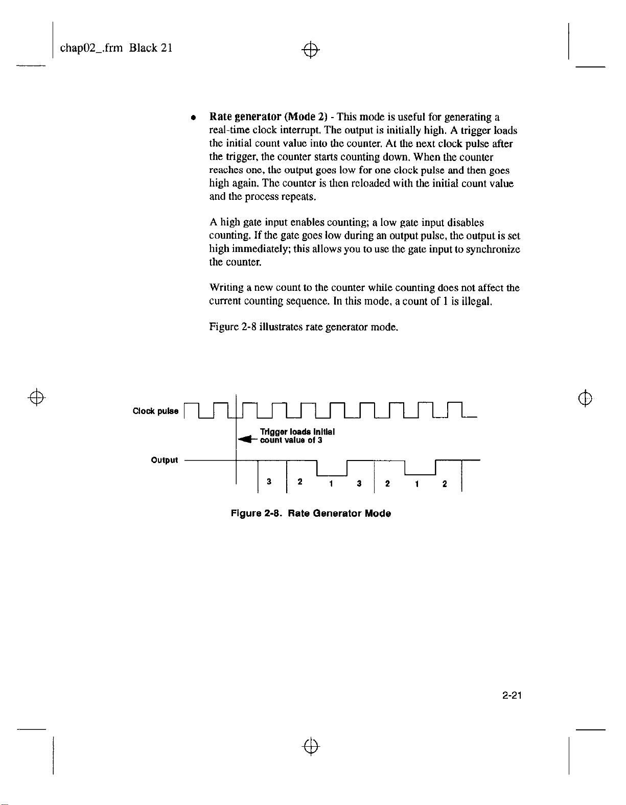
l
Rate generator
(Mode 2) -This mode is useful for generating a
real-time clock interrupt. The output is initially high. A trigger loads
the initial count value into the counter. At the next clock pulse after
the trigger, the counter starts counting down. When the counter
reaches one, the output goes low for one clock pulse and then goes
high again. The counter is then reloaded with the initial count value
and the process repeats.
A high gate input enables counting; a low gate input disables
counting. If the gate goes low during an output pulse, the output is set
high immediately; this allows you to use the gate input to synchronize
the counter.
Writing a new count to the counter while counting does not affect the
current counting sequence. In this mode, a count of 1 is illegal.
Figure 2-8 illustrates rate generator mode.
ClOdI pulse
Figure 2-8. Rate Generator Mode
2-21
Page 37
chap02-.frm Black 22
+b
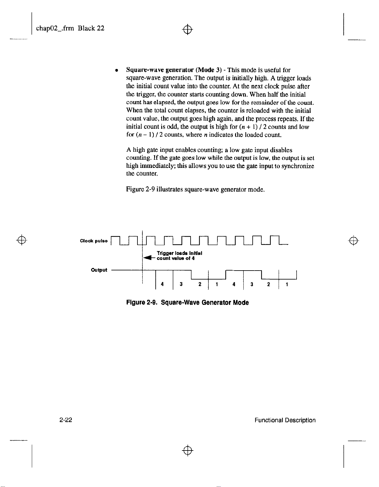
. Square-wave generator (Mode 3) -This mode is useful for
square-wave generation. The output is initially high. A trigger loads
the initial count value into the counter. At the next clock pulse after
the trigger, the counter starts counting down. When half the initial
count has elapsed, the output goes low for the remainder of the count.
When the total count elapses, the counter is reloaded with the initial
count value, the output goes high again, and the process repeats. If the
initial count is odd, the output is high for (n + 1) / 2 counts and low
for (n - 1) / 2 counts, where n indicates the loaded count.
A high gate input enables counting; a low gate input disables
counting. If the gate goes low while the output is low, the output is set
high immediately: this allows you to use the gate input to synchronize
the counter.
Figure 2-9 illustrates square-wave generator mode.
2-22
output
1 I I
14 3
2
Figure 2-9. Square-Wave Generator Mode
2 1
Functional Description
Page 38
chap02-.frm Black 23
Clock
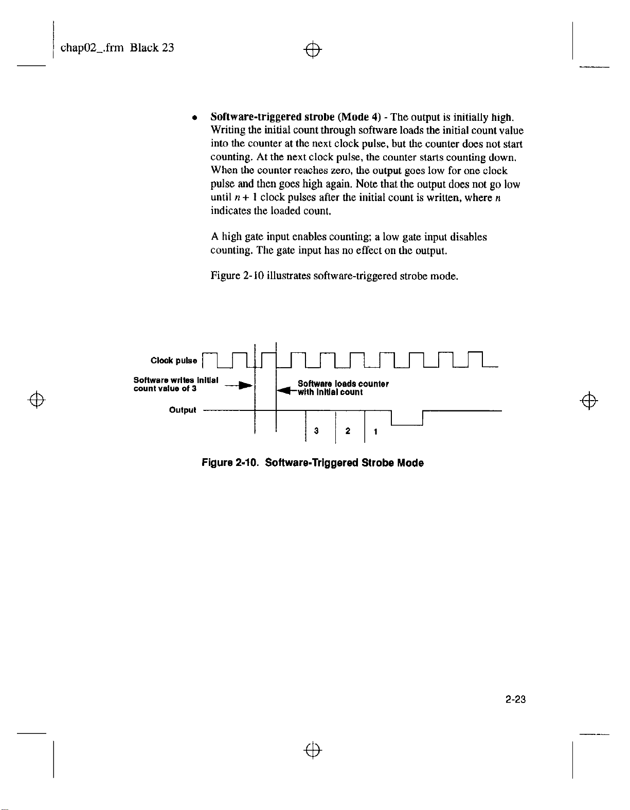
. Software-triggered strobe
Writing the initial count through software loads the initial count value
into the counter at the next clock pulse, but the counter does not start
counting. At the next clock pulse, the counter starts counting down.
When the counter reaches zero, the output goes low for one clock
pulse and then goes high again. Note that the output does not go low
until n + 1 clock pulses after the initial count is written, where n
indicates the loaded count.
A high gate input enables counting: a low gate input disables
counting. The gate input has no effect on the output.
Figure 2- 10 illustrates software-triggered strobe mode.
pulse
I
output
I
(Mode 4) -The output is initially high.
Figure 2-10. Software-Triggered Strobe Mode
2-23
Page 39
chap02-.frm Black 24
fb
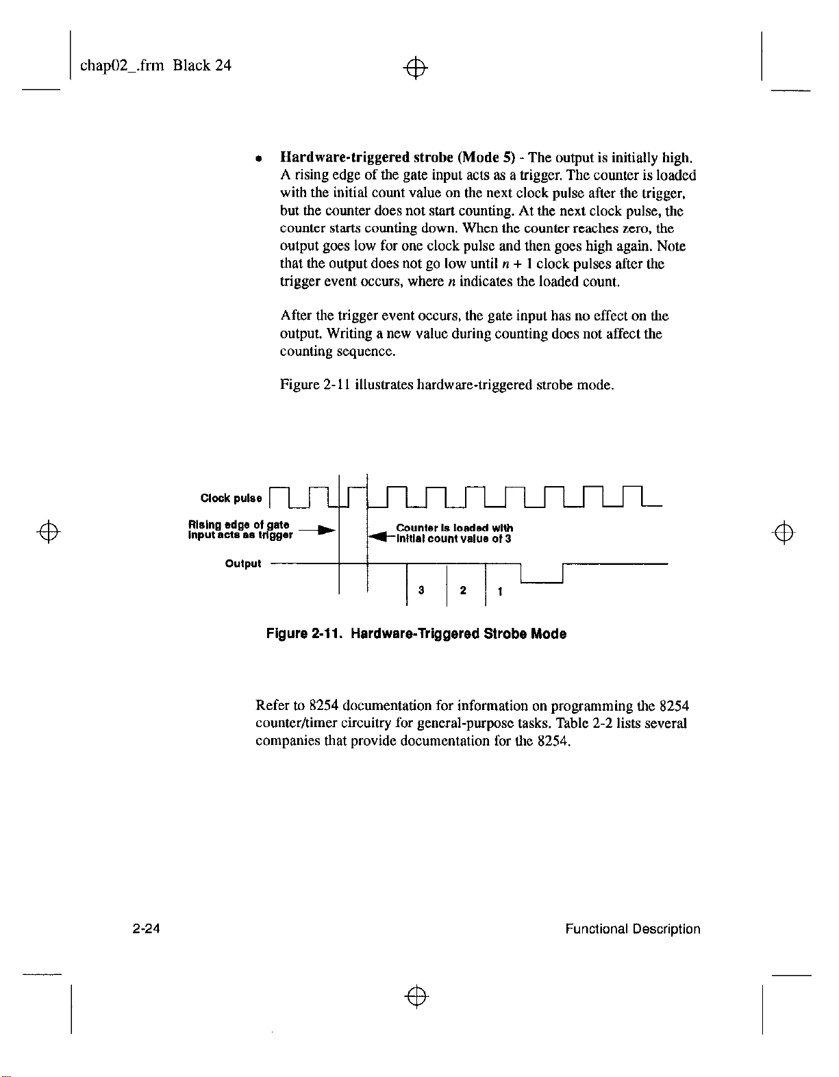
l
Hardware-triggered strobe (Mode
A rising edge of the gate input acts as a trigger. The counter is loaded
with the initial count value on the next clock pulse after the trigger,
but the counter does not start counting. At the next clock pulse, the
counter starts counting down. When the counter reaches zero, the
output goes low for one clock pulse and then goes high again. Note
that the output does not go low until n + 1 clock pulses after the
trigger event occurs, where n indicates the loaded count.
After the trigger event occurs, the gate input has no effect on the
output. Writing a new value during counting does not affect the
counting sequence.
Figure 2- 11 illustrates hardware-triggered strobe mode,
5) - The output is initially high.
Clock
pulse
flislng edge of ate
input act* as I rf gger -
output
Figure 2-11. Hardware-Triggered Strobe Mode
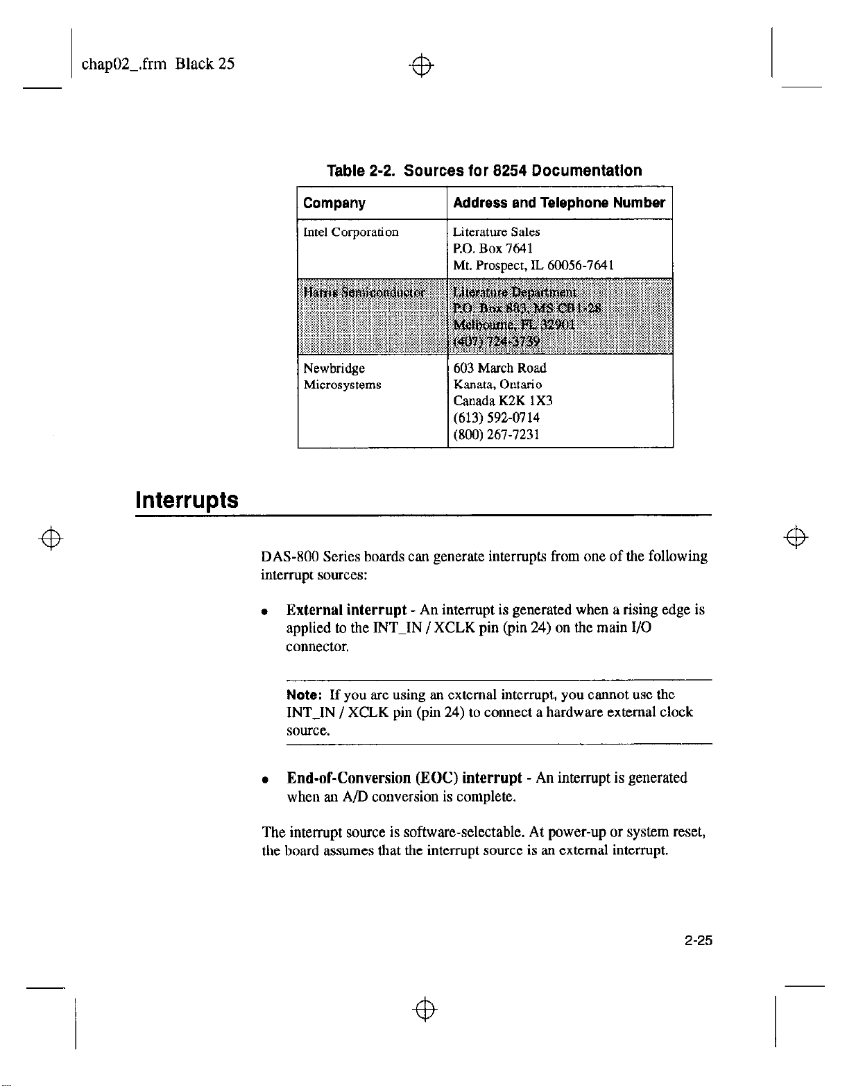
Refer to 8254 documentation for information on programming the 8254
counter/timer circuitry for general-purpose tasks. Table 2-2 lists several
companies that provide documentation for the 8254.
Counter Is loaded wllh
flnldal CO”“t value of 3
2-24
Functional Description
Page 40
chap02-.frm Black 25
Table 2-2. Sources for 8254 Documentation
Company 1 Address and Telephone Number 1
lntel Corporation Literature Sales
P.O. Box 7641
Mt. Prospect, IL 60056-7641
Interrupts
Newbridge
Microsystems
603 March Road
Kanata, Ontario
Canada K2K 1X3
(613) 592-0714
(800) 267-7231
DAS-800 Series boards can generate interrupts from one of the following
interrupt sources:
. External interrupt
- An interrupt is generated when a rising edge is
applied to the INT-IN / XCLK pin (pin 24) on the main I/O
connector.
Note: If you are using an external interrupt, you cannot use the
INT-IN
/ XCLK pin (pin 24) to connect a hardware external clock
source.
. End-of-Conversion (EOC) interrupt
- An interrupt is generated
when an A/D conversion is complete.
The interrupt source is software-selectable. At power-up or system reset,
the board assumes that the interrupt source is an external interrupt.
2-25
Page 41
chapOZ_.frm Black 26
f9
You can select only one interrupt at a time. If you are using an interrupt,
you must select the interrupt level (2, 3,4,5,6, or 7) using a jumper on
the board. If you are not using an interrupt, you can disable interrupts
using a jumper on the board. Refer to page 3-17 for more information.
Power
Note:
enabled and the interrupt source must be an EOC interrunt.
If an interrupt condition is satisfied, an on-board flip-flop is set. If
interrupts are enabled (through both hardware and software), the board
generates an interrupt to the host, driving the selected host interrupt line
to an active state.
The analog circuitry on the DAS-800 board is powered by the f12 V of
the host computer. The DAS-801 and DAS-802 boards contain a DC/DC
converter to provide power to the analog circuitry.
Note:
computers do not have a -12 V power supply. If your computer does not
have a -12 V power supply, you cannot use a DA%800 board.
If you are acquiring data in the background, interrupts must be
Many laptop computers and other types of battery-operated
2-26
The host computer can provide power for EXP-16, EXP- 16/A, and
EXP-GP expansion boards and MB Series backplanes: however, certain
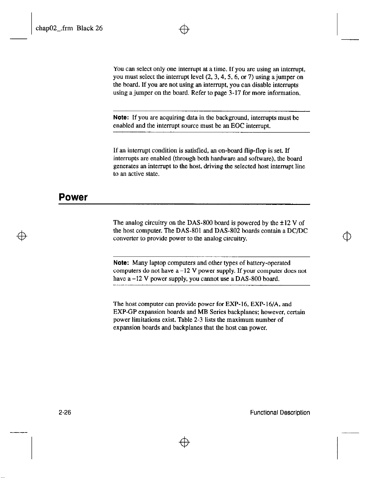
power limitations exist. Table 2-3 lists the maximum number of
expansion boards
and
backplanes that the host can power.
Functional Description
Page 42
chap02-.frm Black 27
Table 2-3. Expansion Board / Backplane Power Limitations
Expansion Board / Maximum Number
Backplane Powered by Host
I
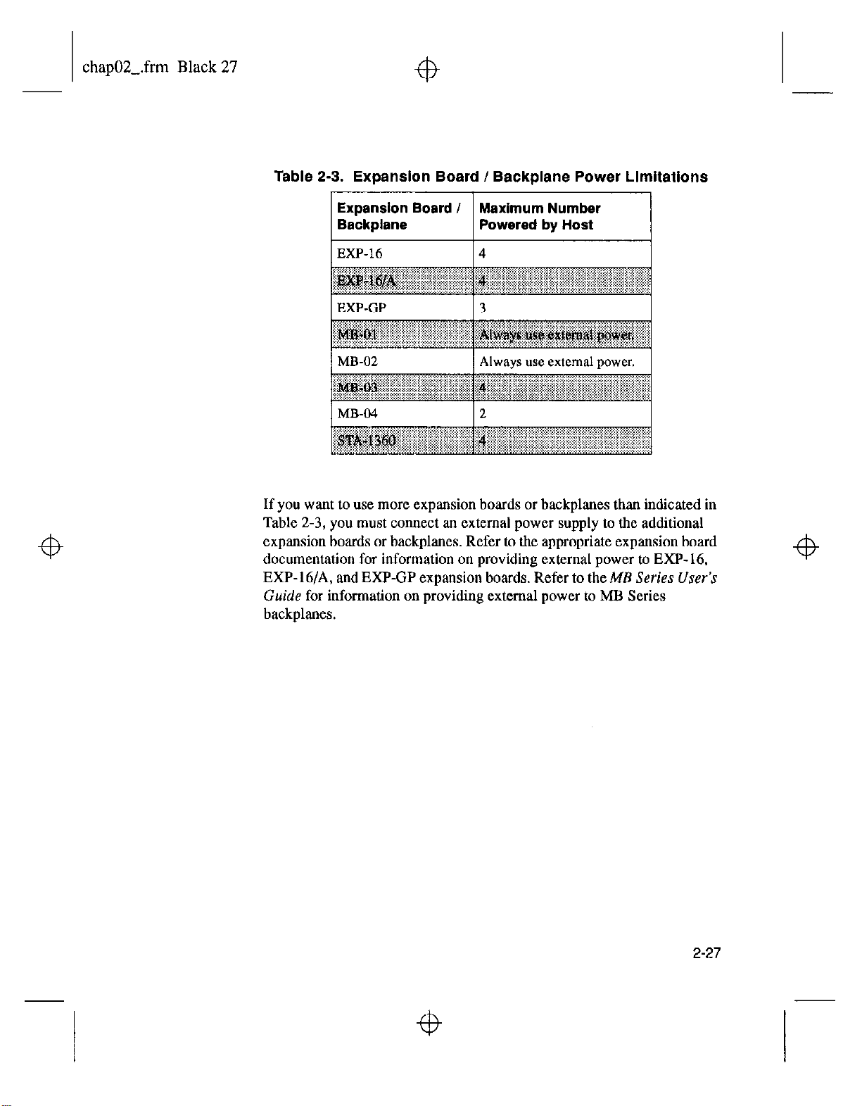
If you want to use more expansion boards or backplanes than indicated in
Table 2-3, you must connect an external power supply to the additional
expansion boards or backplanes. Refer to the appropriate expansion board
documentation for information on providing external power to EXP- 16.
EXP-16/A, and EXP-GP expansion boards. Refer to theME
Guide
for information on providing external power to MB Series
Series User’s
backplanes.
2-27
Page 43

chap02-.frm Black 28
4
Page 44

chap03-.frm Black 1
4
3
Setup and Installation
This chapter describes how to install the software in your computer,
unpack and inspect the board, configure the board, and install the board in
your computer.
If you are familiar with switches and jumpers and with the items that are
configurable on DAS-800 Series boards, you can use Figure 3-1 as a
quick reference for configuring a DA%800 board and Figure 3-2 as a
quick reference for configuring a DAS-801 or DAS-802 board. If you
need additional information, refer to Configuring the Board on page 3-8.
3-1
4
Page 45

chap03-.frm Black 2
BASE ADDRESS
::I
Ai
C
-
J2
Jl
ilOWW q 300H
I”ierrup\ level
(X E disabled)
Figure 3-1. DAS-300 Board
3-2
Setup and Installation
Page 46

chap03-.frm Black 3
BASE ADDRESS
3
’ 2 3 4 5 6 ’
~~~fjfl~~[
A
Base dddnss
b”,“&&:“,,=d
OWWOl = WBH
OWWIO z OlOH
ilOWW = 300H
1111111 s3FBH
SWlwl fhckS2
OOOOI
t
0
1
2
3
4
5
6
7
Input ConfiguratIon
(On rslngleemdsd,
Switch 1 I Channel
Swllch 2 E Channel
Stitch 3 = Channel
Swllch 4 = Channel
Switch 5 z Channel
Switch 6 q Channel
Switch 7 z Channel
Swllch 8 = Channel
Jl
I
I
Interrupt Ioval
(X q disabled)
Off L dlfferenUsl)
Figure 3-2. DAS-8011802 Board
3-3
Page 47

chap03-.frm Black 4
Installing the Software
This section describes how to install the DA%800 Series standard
software package and how to install the ASO- software package from
both DOS and Windows. The contents of these software packages are
described as follows:
. DAS-800 Series standard software package
-This is tbe software
package that is shipped with DAS-800 Series boards; it includes the
following:
- The Control Panel, running under DOS, which allows you to test
all features of DAS-800 Series boards before programming.
-
Libraries of functions for Microsoft QuickBasic, Microsoft
Professional Basic, and Microsoft Visual Basic for DOS.
- Support files, containing such program elements as function
prototypes and definitions of variable types, which are required
by the functions.
-
Utility programs, running under DOS, that allow you to configure
and calibrate DAS-800 Series
-
Language-specific example programs.
-
The External Driver, which is required for programming with
boards.
VIEWDAC, EASYEST LX 1 AG, and ASYST.
l
ASO- software package
- This is the optional Advanced
Software Option for DAS-800 Series boards. You purchase the
ASO- software package separately from the board; it includes the
following:
3-4
-
The Control Panel, running under DOS and Windows, which
allows you to test all features of DAS-800 Series boards before
programming.
-
Libraries of functions for Microsoft C/C++, Borland C/C++, and
Borland Turbo Pascal.
Setup and Installation
Page 48

chap03-.frm Black 5
-
Dynamic Link Libraries (TILLS) of functions for Microsoft Visual
Basic for Windows, Microsoft QuickC for Windows, Microsoft
Visual C++, and Borland Turbo Pascal for Windows.
-
Support files, containing program elements, such as function
prototypes and definitions of variable types, that are required by
the functions.
-
Utility programs, running under DOS and Windows, that allow
you to configure and calibrate DAS-800 Series boards.
-
Language-specific example programs.
Note: To install other software packages, refer to the documentation
supplied with the software package.
Installing the DAS-800 Series Standard Software Package
To install the DAS-800 Series standard software package, perform the
following steps:
1. Make a back-up copy of the supplied disks.
2. Insert disk #1 into the disk drive.
3. Assuming that you are using disk drive A, enter the following at the
DOS prompt:
A:install
The installation program prompts you for your installation
preferences, including the name of the directory you want to copy the
software to. It also prompts you to insert additional disks, as
necessary.
4. Continue to insert disks and respond to prompts, as appropriate.
The installation program expands any files that are stored in a
compressed format and copies all files to the directory you specified
(DAS800 directory on hard disk C if you do not specify otherwise).
3-5
Page 49
chap03-.frm Black 6
Installing the ASO- Software Package
DOS Installation
fb
5. Review the following files:
-
FILESTXT lists and describes all the files copied to the hard disk
by the installation program.
-
README.TXT contains information that was not available when
this manual was printed.
This section describes how to install the ASO- software package from
both DOS and Windows.
To install the ASO- software package from DOS, perform the
following steps:
1. Make a back-up copy of the supplied disks.
2. Insert disk #l into the disk drive.
3. Assuming that you are using disk drive A, enter the following at the
DOS prompt:
A:install
The installation program prompts you for your installation
preferences, including the name of the directory you want to copy the
software to. It also prompts you to insert additional disks, as
necessary.
4. Continue to insert disks and respond to prompts, as appropriate.
The installation program expands any files that are
compressed format and copies all files to the directory you specified
(AS0800 directory on hard drive C if you do not specify otherwise).
5. Review the following files:
-
FIL,ES.TXT lists and describes all the tiles copied to the hard disk
by the installation program.
stored in a
3-6
Setup and Installation
Page 50

chap03-.frm Black 7
Windows installation
- README.TXT contains information that was not available when
this manual was printed.
To install the ASO- software package from Windows, perform the
following steps:
1. Make a back-up copy of the ASO-Windows disk.
2. Insert the ASO-Windows disk into the disk drive.
3. Start Windows.
4. From the Program Manager menu, choose File and then choose Run.
5. Assuming that you are using disk drive A, type the following at the
command line in the Run dialog box, and then select OK:
A:SETUP
The installation program prompts you for your installation
preferences, including the name of the directory you want to copy the
software to.
6. Type the path name and select Continue.
The installation program expands any files that are stored in a
compressed format and copies all files to the directory you specified
(ASOSOthWINDOWS directory on hard drive C if you do not specify
otherwise).
The installation program also creates a DAS-800 Series family group:
this group includes example Windows programs and help tiles.
7. Review the following files:
-
FILES.TXT lists and describes all the files copied to the hard disk
by the installation program.
-
README.TXT contains information that was not available when
this manual was printed.
3-7
Page 51

chap03-.frm Black 8
Umackina the Board
To prevent any damage to your DAS-800 Series board, perform the
following steps when unpacking the board:
1. Remove the wrapped DAS-800 Series board from its outer shipping
carton.
2. Making sure that your computer is turned OFF but grounded, hold the
wrapped board in one hand while placing your other hand firmly on a
metal portion of the computer chassis: this discharges any static
electricity.
3. Carefully remove the board from its anti-static wrapping material.
(You may wish to store the wrapping material for future use.)
4. Inspect the board for signs of damage. If any damage is apparent,
arrange to return the board to the factory; refer to Chapter 7 for more
information.
5. Check the remaining contents of your package against the packing list
to ensure that your order is complete. Report any missing items to the
factory immediately.
6. Once you have determined that the
configure the board. Refer to the next section for configuration
options.
Configuring the Board
You can configure the following items on DAS-800 Series boards:
. Board type @AS-800, DAS-801, or DAS-802).
. Base address (required by the DA%800 Series Function Call Driver
and other software packages to perform DAS-800 Series board
operations).
. Use of C/T2 on the 8254 (cascaded or normal).
board is
acceptable, you can
3-8
Setup and Installation
Page 52

chap03-.frm Black 9
4
Input range type (unipolar or bipolar) for a DAS-801 or DAS-802
board.
Input configuration (single-ended or differential) for each channel on
a DAS-801 or DAS-802 board.
Interrupt level.
Expansion boards used (information includes the number of
expansion boards, the gains used by channels on the expansion
boards, and the channel used as the CJC sensor).
4
Note:
must also set switches on the expansion boards to specify the gains
used by channels on the expansion boards. Refer to the appropriate
expansion board documentation for information about setting the
switches.
You must specify the base address and input configuration by setting
switches on the board and the interrupt level by setting a jumper on the
board. In addition, if you intend to use your DAS-800 Series board with
the DAS-800 Series Function Call Driver, Control Panel, custom controls,
or External Driver or with any application program that requires a
configuration file, you must indicate all your configuration options in a
configuration file.
The following sections describe how to create a configuration file and
how to set the base address, input configuration, and intermpt level.
For EXP-16, EXP-16/A, and EXP-GP expansion boards, you
Creating a Configuration File
A default configuration tile called DASSOO.CFG is provided in both the
DAS-800 Series standard software package and the ASO- software
package. The factory-default settings inDAS8OGCFG are shown in Table
3-1.
4
3-9
Page 53

chap03-.frm Black 10
Table 3-I. Default Configuration
4
Attribute
Board type
8254 Clr2 usage
~~~~~~~~~~~.~~~~~~~~ ~~~~~~~~~~~~~~~~
.:.:; .,.....,.,........./....,./.......... . .._ I ..j..........j.jj....j..... :.:../,.< ,...,.,.....,...,.,,....,.... :<.:.:. :.:.:.:.:.:,.,:.:.::.‘.~ :...:.:,..: .,... I:.
Channel 0 input configuration Single-ended
Default Configuration
1 DAS-800
Cascaded
I
4
3-10
Gain of EXP-GPs
Notes
’ The setting in the configuration file must match the settings of
the switches and jumper on the board.
‘The default base address for board 0 is 300H. If you are using
multiple DAS-800 Series boards, the default base address for
board 1 is 308H, the default base address for board 2 is 310H.
and the default base address for board 3 is 318H.
3 For the purposes of the configuration file, an MB-02 backplane
is the same as anEXP-16 expansion board. Therefore, if you are
using MB-02 backplanes instead of EXP-16 or EXP-16/A
expansion boards, specify the number of MB-02 backplanes
here.
1 [N/Al
Setup and Installation
4
I
Page 54

chap03-.frm Black 11
+b
4 If you are using MB-02 backplanes instead of EXP-16 or
EXP-16/A
channels are set to 1.
If the default settings are appropriate for your application and match the
settings of the switches and jumper on the board, you can skip the rest of
this section and proceed directly with installing the board. Refer to page
3-19 for information on installing the board.
If the default settings are not appropriate for your application, you must
create a new configuration file or modify an existing configuration file to
specify the correct configuration options. The DSOOCFG.EXE
configuration utility, shipped with both the DAS-800 Series standard
software package and the ASO- software package, is provided for this
purpose.
To create or modify a configuration file, perform the following steps:
1. Invoke the configuration utility from DOS or Windows, as follows:
expansion boards, make sure that the gains of all
- If you are running under
DEOOCFG.EXB configuration utility, enter the following at the
DOS prompt:
DBOOCFG
wherefilename is the name of the configuration file you wish to
create or modify.
-
If you are running under Windows,
Manager File menu. Enter the following in the box and select
OK:
D800CFG
wherefilename is the name of the configuration tile you wish to
create or modify.
Make sure that you enter the correct path to DSOOCFG.EXE, or
use the Browse button to find this file.
If the utility finds a configuration file namedfilename, it displays the
opening menu screen with the name of the existing configuration file
shown. If the utility does not fmd a configuration file named
filename
filename
DOS,
from the directory containing the
choose Run from the Program
3-11
Page 55
chap03-.frm Black 12
+B
filename, it displays the opening menu screen withfilename shown;
this file contains the default configuration options. If you do not enter
a tile name, the utility assumes that you want to modify the default
configuration file DASSOO.CFG.
Note:
Series standard software package and the ASO- software package,
use the default configuration file DASSOO.CFG. If you intend to use
the example programs, make sure that DASSOb.CFG exists and that
the settings in DASSOO.CFG match the settings of your
2. On the opening menu screen, enter the number of DAS-800 Series
boards you plan to configure (1 to 4).
The utility displays the configuration options for the first board
(board 0). The number of the board is shown in the upper-left corner
of the menu box.
3. To modify any of the configuration options, use the arrow keys to
highlight the option you want to change, press [Enter] to display a list
of available settings, use the arrow keys to highlight the appropriate
setting, and press @nter]. These instructions are summarized in the
Commands/Status box at the bottom of the screen.
When the configuration options for this board are correct, press [N] to
display the configuration options for the next board.
The example programs, provided with both the DAS-800
board.
3-12
4. If you modify the base address, input configuration, or interrupt level,
you can press [S] to display the corresponding switch or jumper
settings. You can use this display as a reference when setting the
switches and jumper.
Note:
provided in the following sections. Refer to page 3-13 for information
on setting the base address; refer to page 3-16 for information on
setting the input configuration; refer to page 3-17 for information on
setting the interrupt level.
Information on setting the switches and jumper is also
Setup and Installation
Page 56
chap03-.frm Black 13
Setting the Base Address
5. After you modify the appropriate configuration options for all boards,
press [Esc]. The utility asks if you want to save the new settings.
6. Press [Y] to save the settings to the configuration file you specified.
DAS-800 Series boards are shipped with a base address of 300H. If any of
the address locations between 300H and 307H are being used by another
resource in your system (including another DAS-800 Series board), you
must reconfigure the base address using the base address switch block
(labeled Sl on the DAS-800 board: labeled S2 on DAS-801 and DAS-802
boards).
Note: The default base address settings in the configuration file are 300H
for board 0,308H for board 1,310H for board 2, and 318H for board 3.
Make sore that the switch settings for each board match the settings in the
configuration tile for each board.
The base address switch block contains seven switches, labeled 1 through
7. Switch 1 corresponds to the most significant bit (MSB) of the base
address; switch 7 corresponds to the LSB of the base address. The
location of the base address switch block on the DAS-800 board is shown
in Figure 3-l on page 3-2, the location of the base address switch block on
the DAS-801 and DAS-802 boards is shown in Figure 3-2 on page 3-3.
You place a switch in the ON position (logic 0) by sliding the switch
toward the top (numbered side) of the switch block. You place a switch in
the OFF position (logic 1) by sliding the switch toward the bottom
(unnumbered side) of the switch block.
Figure 3-3 illustrates the setting for a base address of 280H; switches 1
and 3 are in the OFF position and switches 2,4, 5, 6, and 7 are in the ON
position.
3-13
Page 57

chap03-.frm Black 14
Figure 3-3. Setting the Base Address
Table 3-2 lists I/O addresses commonly used by IBM PC/XT, AT, and
compatible computers. Determine an even boundary of eight I/O
addresses within the range of OOOH to 3FSH that is not being used by
another resource in your system (including another DA%800 Series
board), and set the switches to the appropriate
base address.
Table 3-2. I/O Address Map (OOOH to 3FFH)
1 Address Range 1 Use
OOOH to OOFH
OAOH to OAFH
8237 DMA #I
NM1 mask register (XT)
200H to 2FFH Game /control
I
I
I
3-14
Setup and Installation
Page 58

chap03_.frm Black 15
Table 3-2. l/O Address Map (OOOH to 3FFH) (cont.)
Address Range U-Se
238Hto
23BH Busmouse
3-15
I
Page 59
chap03-.frm Black 16
f@
Notes:
The DBOOCFG.EXE configuration utility allows you to set base
addresses between 200H and 3FSH‘ only. Therefore. if you are using your
DAS-800 Series board with software that requires a configuration file,
you must specify an even boundary of eight I/O addresses within the
range of 200H to 3F8H.
If you press [S] after you specify the base address in the configuration
file, the configuration utility illustrates the appropriate switch settings for
you; refer to page 3-9 for more information about the configuration utility.
Setting the Input Configuration
DAS-801 and DAS-802 boards are shipped with the input configuration
for all channels set to single-ended. If this is not appropriate for your
application, you can reconfigure the input configuration on a
channel-by-channel basis using the input configuration switch block
(labeled Sl).
Note:
single-ended for all channels. Make sure that the switch settings match
the settines in the confieuration file.
The default input configuration in the configuration file is also
3-16
The input configuration switch block contains eight switches, labeled 1
through 8. Switch 1 corresponds to channel 0: switch 2 corresponds to
channel 1, and so on. The location of the input configuration switch block
on the DAS-80 1 and DAS-802 boards is shown in Figure 3-2 on page 3-3.
You place a switch in the ON position (single-ended) by sliding the switch
toward the top (numbered side) of the switch block. You place a switch in
the OFP position (differential) by sliding the switch toward the bottom
(unnumbered side) of the switch block.
Figure 3-4 illustrates the setting for channels 0. 5, and 7 configured as
single-ended (switches 1, 6, and 8 are in the ON position) and channels 1,
2, 3.4, and 6 configured as differential (switches 2,3,4, 5, and 7 are in
the OFF position).
Setup and Installation
Page 60

chap03-.frm Black 17
+b
Figure 3-4. Setting the Input Conflguration
Notes: Since
configuration, they do not contain an input configuration switch block.
If you press [S] after you specify the input configuration in the
configuration file, the configuration utility illustrates the appropriate
switch settings for you; refer to page 3-9 for more information about the
configuration utility.
DAM00 boards always use a single-ended input
Setting the Interrupt Level
DAM00 Series boards are shipped with interrupts disabled. If you want
to use interrupts, you must set an appropriate interrupt level using jumper
block Jl.
Notes:
disabled.
configuration file.
If you intend to acquire data in the background, you must enable
interrupts by setting an interrupt level.
The default interrupt level in the configuration file is also
Make
sure that the jumper setting matches the setting in the
Jumper block Jl contains seven pairs of jumper posts, labeled 2.3,4,5,6,
7, and X (disabled). You set the interrupt level by placing the supplied
jumper clip over the appropriate posts. Note that you can set only one
interrupt level at a time.
3-17
Page 61

chap03-.frm Black 18
Figure 3-5 illustrates the setting for intermpt level 5; the jumper clip is
over the posts labeled 5.
2 3
Figure 3-5. Setting the Interrupt Level
4
5 6
7 X
Table 3-3 lists interrupt levels commonly used by IBM PC/XT, AT, and
compatible computers. Select an intemtpt level that is not being used by
another resource in your system (including another DAS-800 Series
board), and set the jumper to the appropriate interrupt level. It is
recommended that you select intemtpt level 3.4.5, or 7, if available.
Table 3-3. Interrupt Levels
Level Use
2
Reserved (XT), interrupts 8 to 15 (AT)
3-I 8
Note:
If you press [S] after you specify the interrnpt level in the
configuration file, the configuration utility illustrates the appropriate
jumper setting for you; refer to page 3-9 for more information about the
configuration utility.
Setup and Installation
Page 62
chap03-.frm Black 19
Installing the Board
+b
Before installing a DA%800 Series board in your computer, make sure
that the switches and jumper on the board are set appropriately and that
the jumper and switch settings match the settings in the configuration file.
Refer to page 3-8 for more information,
Caution:
damage to your computer.
To install the board, perform the following steps:
1. Tnm power to the computer and all attached equipment OFF,
2. Remove the computer chassis cover.
3. Select an available slot. The DAS-800 requires a single, short slot; the
4. Loosen and remove the screw at the top of the blank adapter plate,
5. Insert and secure the board connector in tbe selected slot.
6. Replace the computer chassis cover.
7. Plug in all cords and cables
8. Tnm power to the computer ON.
Installing or removing a board with the power ON can cause
DAS-801 and DAS-802 require a single, l/2-slot.
and then slide the plate up and out to remove.
After you install the DAS-800 Series board in the computer, you can
attach an expansion board, if necessary, and wire the appropriate signals
to the board; refer to Chapter 4 for information. Before writing your
application program, you can test the functions of the DAS-800 Series
board using the Control Panel under DOS or Windows; refer to Chapter 5
for more information.
Refer to the documentation provided with your computer for more
information on installing boards.
3-19
Page 63

chap03-.frm Black 20
4
4
Page 64

chap04-.frm Black 1
4
Cabling and Wiring
This chapter describes how to attach accessory and expansion boards to a
DAS-800 Series board, how to connect signals to a DAS-800 Series
board, and how to synchronize conversions on multiple DAS-800 Series
boards.
4
Note:
make sore that power to your computer and any accessories attached to
the DAM00 Series board are OFF.
Before you make any connections to a DAS-800 Series board,
Attaching Accessory and Expansion Boards
You attach an STC-37 screw terminal connector, STA-08 or STA-08PGA
screw terminal accessory, or EXP-16, EXP-16/A, or EXP-GP expansion
board to a DAS-800 Series board through the main I/O connector, a
37-pin, D-type connector that is labeled J2 on the board. The main I/O
connector and its pin assignments on a DAS-800 board are shown in
Figure 4- I: the main I/O connector and its pin assignments on a DAS-801
or DAS-802 board are shown in Figure 4-2. Refer to Appendix B for a
more detailed description of the pins.
4
4
4-1
Page 65

chap04-.frm Black 2
4
Top of Board (Rear View)
VREF
LLCOM Pin 16 . :
LLCOM Ph17 .
LLCOM Ph16 . :
LLCOM Ph15 . .
LLCOM Ph14
LLCOM Pill13 .
LLCOM
DIQCOM Pill11 . :
OP4
OP3
OP2
OPI
OUT2
OUT1
CLKl
OUT0
CLKO
+12v
Pill 19 .
l
pin12 .’
pin10 . .
Pill9 . .
Pln6 . .
Pln7 . .
PI” 6
Pi” 6
Ph4 . :
PI”3 . .
Phi2 . ,
Phi .
: ’
Ph 37 IN0
Pln 36 IN1
Pin 35 IN2
PM 34 IN3
Pill 33 IN4
,
Pln 32 IN6
Pill 31 IN6
Ph 30 IN7
Pln 29
Pin 26
Pln 27 IP3
Pill 26 IP2
Pln 25 IPliTRlG
Pin 24 INT-IN/XCLK
Pln 23 QATEP
Pi” 22 QATEI
Pill21
Pin 20 -12v
+6 v
DIG COM
GATE0
Figure 4-l. Main l/O Connector on a DAM00 Board
4-2
Cabling and Wiring
Page 66

chap04Lfrm Black 3
+9
Top of Board (Rear View)
INO-
INlIN2IN3IN4INC
INSIN7DIG COM
OP4
OP3
OP2
OPl
OUT2
OUWCCLK
CLKI
OUT0
CLKO
+12 V
Phl9 r-h “,_..Pill19 . : ;;:,j;
Pin17 l
P’n’6 ’ . P,“34
Pl”15 l
pl”‘2 l
Pill11 .
Ph 10
Pln5 I . - lb;.;;
Ph4 . :
Pl”3
Pl”2 ’ . Pi”20
Ph 1 .
. Ph35
. PI”33
. PI”30
. ; Pln29
^.~~ ^^
* . . . _”
Ph 22
l
. PI”21
J
INO*
IN1 +
IN2+
IN3+
IN4+
INS+
IN&
IN7+
+5V
InO co+4
IP3
IP2
IPl/TRlG
INT-lN/XCLK
OATEZ
QATEI
OATEO
-12 v
Figure 4-2. Main I/O Connector on a DAS-801 or DAS-802 Board
You attach an STC-37 screw terminal connector directly to the main I/O
connector on the DAS-800 Series board. You attach an STA-08 or
STA-OXPGA screw terminal accessory or an EXP-16, EXF-16/A, or
EXP-GP expansion board to the main I/O connector on the DAS-800
Series board using either a C-1800 or S-1800 cable. The C-1800 is tbe
unshielded version of the cable; the S-1800 is the shielded version of the
cable.
Attaching an STG37 Screw Terminal Connector
The screw terminals on the STC-37 screw terminal connector allow you
to connect field wiring to a DAS-800 Series board. The screw terminals
are labeled from 1 to 37 and correspond directly to the functions of the
pins on the main I/O connector on the board. For example, since pin 24 is
assigned to the external clock source, use screw terminal 24 to attach a
hardware external clock. Refer to Appendix B for a complete list of pin
assignments.
4-3
Page 67

chap04-.frm Black 4
To connect an STC-37 to a DAS-800 Series board, directly attach the
37-pin connector on the STC-37 to the main I/O connector on the
DAS-800 Series board. Figure 4-3 illustrates tbe connection of an STC-37
to a DAS-800 Series board.
I-
0
37
Ll
0
0
31
u
0
33
DAS.600 Series Board
10000000000r
L?
0
0
0
0
0
1
0
0
I I
0
P
0
2:
Ll
I 11g
gZ-W,“,“,“w Termlnal
Figure 4-3. Attaching an STC-37 Screw Terminal Connector
Attaching an STA-08 I STA-08PGA Screw Terminal Accessory
The screw terminals on the STA-08 screw terminal accessory allow you to
connect field wiring to a DAS-800
STA-OSPGA screw terminal accessory allow you to connect field wiring
to a DAM01 or DAS-802
name of the board function to which it is connected, the screw terminals
correspond directly to the functions of the pins on the main I/O connector
on the
board.
board.
board;
Each screw terminal is labeled with the
the screw terminals on the
4-4
Cabling and Wiring
Page 68
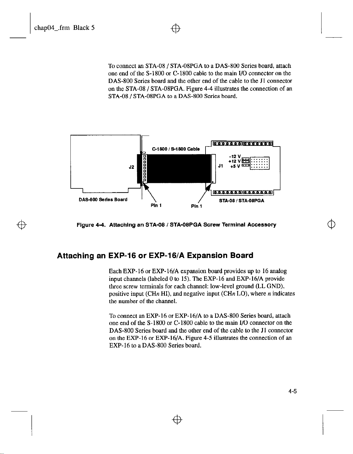
chap04-.frm Black 5
To connect an STA-08 / STA-OSPGA to a DAS-800 Series board, attach
one end
DAS-800 Series
of the S-1800 or C-1800
board and
the other end of tbe cable to the Jl connector
cable
to the main I/O connector on the
on the STA-08 / STA-OSPGA. Figure 4-4 illustrates the connection of an
STA-08 / STA-OSPGA to a DAS-800 Series board.
Cl 900 /S-1900 Cable
Jl
1
DAS-BW Serlss Board
Ph 1
Figure 4-4. Attaching an STA-08 / STA-OBPGA Screw Terminal Accessory
Ph 1
m-r
STA.08 / STA.OBPGA
Attaching an EXP-16 or EXP-16/A Expansion Board
Each EXP-16 or EXP-16/A expansion board provides up to 16 analog
input channels (labeled 0 to 15). The EXP-16 and EXP-16/A provide
three screw terminals for each channel: low-level ground (LL GND),
positive input (CHn HI), and negative input (CHn LO), where n indicates
the number of the channel.
m-L
To connect an EXP-16 or EXP-16/A to a DAS-800 Series
board,
attach
one end of the S-1800 or C-1800 cable to the main I/O connector on the
DAS-800 Series board and the other end of the cable to the Jl connector
on tbe EXP-16 or EXP-16/A. Figure 4-5 illustrates tbe connection of an
EXP-16 to a DAS-800 Series board.
4-5
Page 69
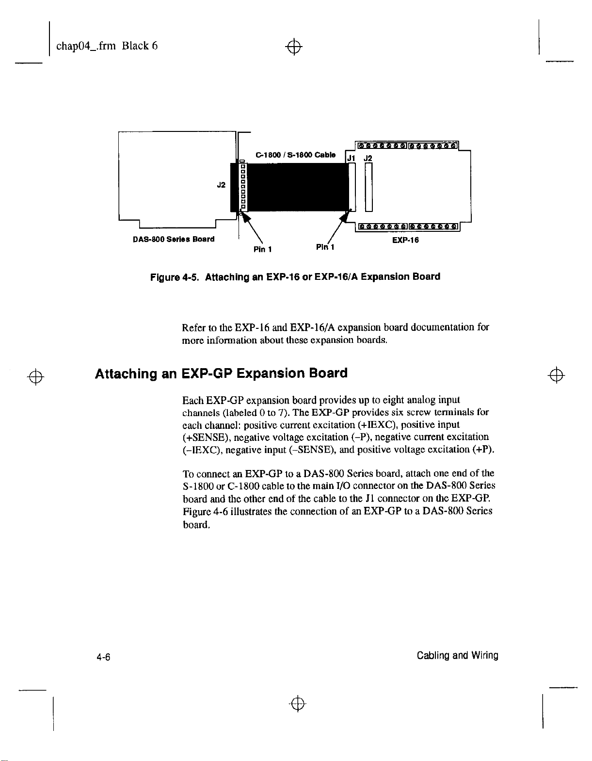
chap04Lfrm Black 6
DAS-800 Ssrlea Board
Figure 4-J. Attaching an EXP-16 or EXP-16/A Expansion Board
Refer to the EXP-16 and EXP-16/A expansion board documentation for
more information about these expansion boards.
Attaching an EXP-GP Expansion Board
Each EXP-GP expansion board provides up to eight analog input
channels (labeled 0 to 7). The EXF-GP provides six screw terminals for
each channel: positive current excitation (+IBXC), positive input
(+SENSE), negative voltage excitation (-P), negative current excitation
(-IEXC), negative input (-SENSE), and positive voltage excitation (+P).
To connect an EXP-GP to a DAM00 Series board, attach one end of the
S-1800 or C-1800 cable to the main I/O connector on the DAS-800 Series
board
and
the other end of the cable to the Jl connector on the EXP-GP.
Figure 4-6 illustrates the connection of an EXP-GP to a DAS-800 Series
board.
4-6
Cabling and Wiring
Page 70

chap04-.frm Black 7
43
C-1200 / 5.1800 Gable
Ph 1
P,” 1
/
DAS.SW Sarles Board
Figure 4-6. Attaching an EXP-GP Expansion Board
II
’ \
Refer to the EXP-GP expansion board documentation for more
information about this expansion board.
Attaching an MB Series Backplane
Refer to the MB Series
DAS-800 Series boards to MB Series backplanes.
User’s
Guide for information on connecting
Connecting Multiple Expansion Boards
You can daisy-chain up to eight EXP-16, EXP-16/A. and/or EXP-GP
expansion boards to provide up to 128 analog input channels. You
connect the first expansion board to the DAS-800 Series board by
attaching one end of an S-1800 or C-1800 cable to the main I/O connector
on the DAS-800 Series board and the other end of the cable to the Jl
connector on the expansion board. To connect additional expansion
boards, attach one end of an S-1800 or C-1800 cable to the J2 connector
on the previous expansion board and the other end of the cable to the Jl
connector on the next expansion board in the chain.
4-7
Page 71
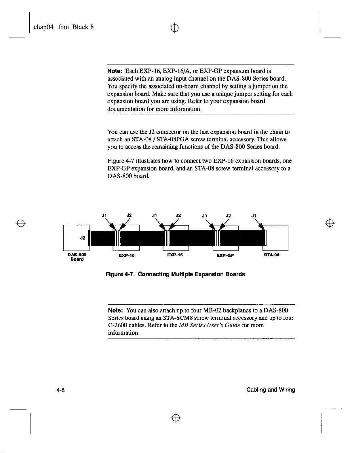
chap04Lfrm Black 8
Note:
Each EXP-16, EXP-16/A, or EXP-GP expansion board is
associated with an analog input channel on the DAS-800 Series board.
You specify the associated on-board channel by setting a jumper on the
expansion board. Make sure that you use a unique jumper setting for each
expansion board you are using. Refer to your expansion board
documentation for more information.
You can use the J2 connector on the last expansion board in the chain to
attach an STA-08 / STA-08PGA screw terminal accessory. This allows
you to access the remaining functions of the DAS-800 Series board.
Figure 4-7 illustrates how to connect two EXP-16 expansion boards, one
EXP-GP expansion board, and an STA-08 screw terminal accessory to a
DAS-800 board.
Jl 52
J1
52
J,
J2 Jl
4-8
EXP-16
Figure 4-7. Connecting Multiple Expansion Boards
EXP-16
EXP-GP
STA-06
Note: You can also attach up to four MB-02 backplanes to a DAS-800
Series board using an STA-SCM8 screw terminal accessory and up to four
C-2600
cables. Refer to the ME
Series User’s Guide
for more
information.
Cabling
and Wiring
Page 72
chap04Lfrm Black 9
Connecting Signals
This section describes how to wire signals to a DAS-800 Series board,
Although the illustrations in this section show a direct connection to a pin
on the main I/O connector, you will actually wire your signal to a screw
terminal on an accessory or expansion board or to a user-supplied, female
37-pin D connector. Appendix B lists the functions associated with each
pm on the main I/O connector.
The DAS-800 board contains both digital commons and low-level analog
commons. Use a digital common for all digital signal returns and power
supply returns; use a low-level analog common for all analog signal
returns.
The DAS-801 and DAS-802 boards contain digital commons, but no
dedicated low-level analog commons. If you are using all eight analog
input channels and all eight channels are configured for differential input,
you must connect a bias return path to a digital common instead of a
low-level analog common. If at least one channel is unused or configured
for single-ended input, you can use the negative side of the channel as a
low-level analog common.
When wiring analog input signals, it is recommended that you terminate
all unused input channels to low-level ground; this prevents the internal
amplifier circuitry from saturating if you select an unconnected input and
ensures the accuracy of your data.
Connecting an Analog Input Signal to a Single-Ended Input
Figure 4-8 illustrates how to connect an analog input signal to
single-ended analog input channel 0 on a DAS-800 board.
4-9
Page 73

chap04-.frm Black 10
I
Figure 4-8. Single-Ended Input
DAS-800 Board
Connecting an Analog Input Signal to a Differential Input
For differential input configurations, you must provide a bias current
return path. If at least one channel is unused or configured for
single-ended input, use the negative side of that channel as the low-level
analog common; otherwise, use the digital common.
Figure 4-9 illustrates how to connect an analog input signal to differential
analog input channel 0 on a DAS-801 board for output resistances both
less than and greater than 100 t2 Since analog input channel 7 is not used,
the bias current return path is connected to the negative side of channel 7.
4-I 0
Cabling and Wiring
Page 74
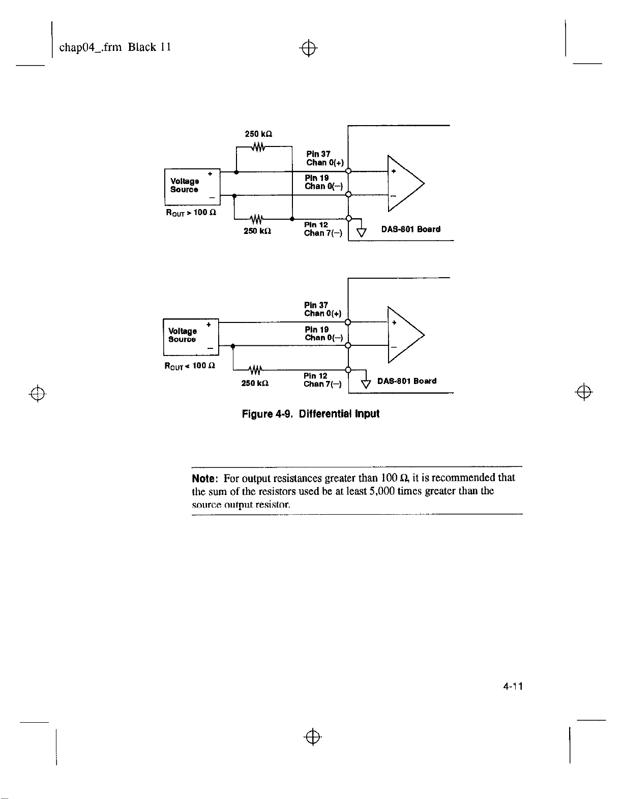
chap04-.frm Black 11
250kCl
r
=b
250
kn
Figure 4-Q. Differential Input
a
+
DAS-901 Board
I/
DAS.901 Board
Note:
For output resistances greater than 100 Q it is recommended that
the sum of the resistors used be at least 5,000 times greater than the
source output resistor.
4-11
Page 75
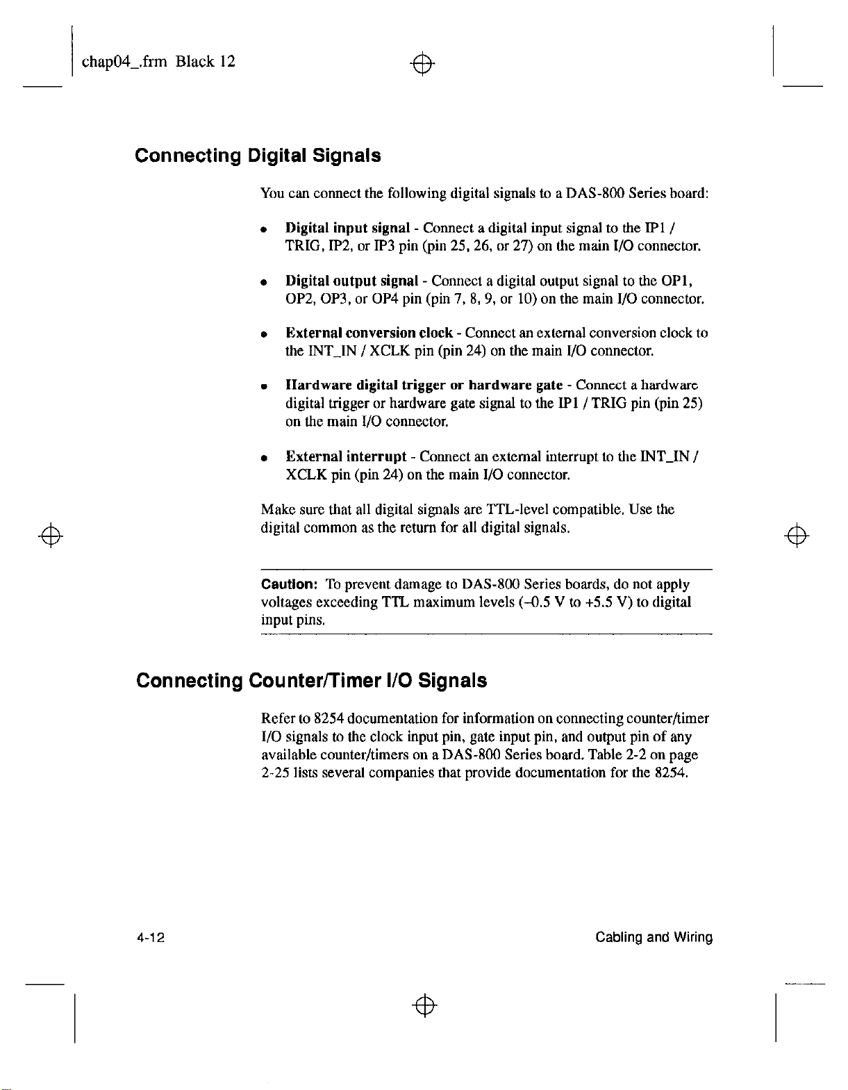
chap04-.frm Black 12
Connecting Digital Signals
You can connect the following digital signals to a DAS-800 Series board:
Digital input signal
- Connect a digital input signal to the IPl /
TRIG, IP2, or IP3 pin (pin 25,26, or 27) on the main I/O connector.
Digital output signal
- Connect a digital output signal to the OPl,
OP2, OP3, or OP4 pin (pin 7, 8,9, or 10) on the main I/O connector.
External conversion clock
- Connect an external conversion clock to
the INT-IN / XCLK pin (pin 24) on the main I/O connector.
Hardware digital trigger or hardware gate -
Connect a hardware
digital trigger or hardware gate signal to the IPl /TRIG pin (pin 25)
on the main I/O connector.
External interrupt -
Connect
an external
interrupt to the INT-IN /
XCLK pin (pm 24) on the main I/O connector.
Make sure that all digital signals are TTL-level compatible. Use the
digital common as the return for all digital signals.
Caution:
To prevent damage to DAS-800 Series boards, do not apply
voltages exceeding TTL maximum levels (-0.5 V to +5.5 V) to digital
input pins.
Connecting Counter/Timer I/O Signals
Refer to 8254 documentation for information on connecting counter/timer
I/O signals to the clock input pin, gate input pin, and output pin of any
available counter/timers on a DAS-800 Series board. Table 2-2 on page
2-25 lists several companies that provide documentation for the 8254.
4-12
Cabling and Wiring
Page 76
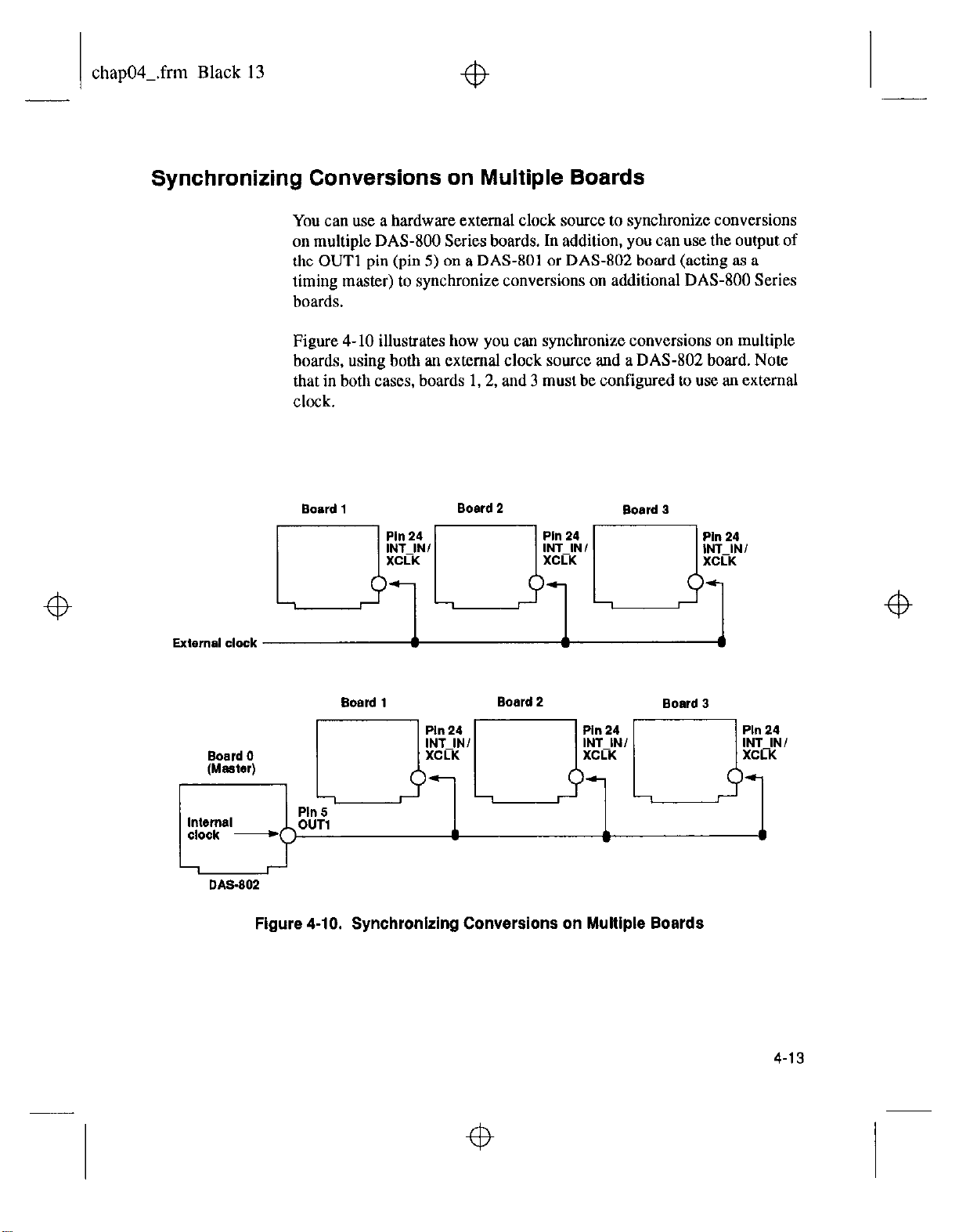
chap04Lfrm Black 13
Synchronizing Conversions on Multiple Boards
4
You can use a hardware external clock source to synchronize conversions
on multiple DAS-800 Series boards. In addition, you canuse the
the OUT1 pin (pin 5) on a DAS-801 or DAS-802 board (acting as a
timing master) to synchronize conversions on additional DAS-800 Series
boards.
Figure 4- 10 illustrates how you can synchronize conversions on multiple
boards, using both an external clock source and a DAS-802 board. Note
that in both cases, boards 1,2, and 3 must be configured to use an external
clock.
output
of
4
Internal
clock -
Board 1 Board 2
Board 1
Ph 5
Figure 4-10. Synchronlzlng Conversions on Multiple Boards
Board 2
Board 3
Board 3
4
4
4-13
Page 77
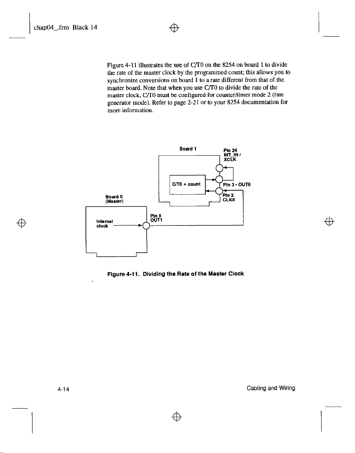
chap04Lfrm Black 14
+b
Figure 4- 11 illustrates the use of CflO on the 8254 on board 1 to divide
the rate of the master clock by the programmed count; this allows you to
synchronize conversions on board 1 to a rate different from that of the
master
master clock, C/l’0 must be configured for counter/timer mode 2 (rate
generator mode). Refer to page 2-21 or to your 8254 documentation for
more information.
board.
Note that when you use C/TO to divide the rate of the
Board
1
Pill 24
4
Board 0
(Master)
Pill 5
Internal
clock -
Figure 4-11. Dividing the Rate of the Master Clock
OUT1
4
4-14
Cabling and Wiring
4
Page 78
chap05-.frm Black 1
4
5
The Control Panel
The Control Panel is the utility that allows you to test the functions of
DAS-800 Series boards. The Control Panel is shipped in two versions.
The DOS version (CTL800.EXE) is shipped with both the DAS-800
Series standard software package and the ASO- software package; the
Windows version (CTL800W.EXE) is shipped with the ASOsoftware package only.
To use the Control Panel, perform the following steps:
1. Invoke the Control Panel from DOS or Windows, as follows:
-
If
you are running under
CTLBOO.EXE utility, enter the following at the DOS prompt:
CTLSOO
-
Ifyou are running under Windows,
Manager File menu. Enter the following in the box and select
OK:
CTLEOOW
Make sure that you enter the correct path to CTLSOOW.EXE, or
use the Browse button to find tbis file.
After you invoke the Control Panel, the software displays the Open
Configuration File panel, asking you to specify the configuration
options you want to use.
DOS,
from the directory containing the
choose Run from the Program
4
5-1
Page 79
chap05-.frm Black 2
2. Select the configuration options in one of the following ways:
- Select Cancel to use the default configuration options. Refer to
Table 3- 1 on page 3-10 for a list of the default configuration
options. If the software does not find a board at the default base
address (300H), an error message is displayed and the Control
Panel terminates.
-
Highlight the name of a configuration file in the File Name box
and select OK. The software uses the configuration options from
the selected configuration tile.
Note:
You can also specify a configuration file when you invoke the
Control Panel from DOS or Windows. Use the /Ffilenume option,
wherefilename is the name of the configuration file you want to use.
After you specify the appropriate configuration options, the software
displays the DAS-800 TEST & CONTROL panel, which is the main
control panel. This panel allows you to acquire, display, and transfer
analog input data and set up and display the parameters.
3. Select the appropriate buttons to perform an analog input operation.
For information about the meaning of the analog input parameters,
use the Online Help provided with the Control Panel or refer to
Chapter 2.
4. To perform a digital I/O or counter/timer I/O operation, choose
Digital and Counter7Timer from the Panels menu. The software
displays the DIGITAL I/O & COUNTER/TIMER panel. This panel
controls the output and input of digital signals and acts as an interface
to the 8254 counter/timer circuitry.
5. Select the appropriate buttons to perform a digital I/O or
counter/timer I/O operation. For information about the meaning of the
digital I/O or counter/timer I/O parameters, use the Online Help
provided with the Control Panel or refer to Chapter 2.
5-2
6. When you have finished the digital I/O or counter/timer I/O
operation, select OK or Cancel to return to the DAS-800 TEST &
CONTROL panel.
The Control Panel
Page 80
chap05-.frm Black 3
7. If you are running under Windows,
Exchange (DDE) to transfer
you can use Dynamic Data
data
to another Windows program by
choosing DDE from the Panels menu.
8. When you have finished using the Control Panel, choose one or more
of the options from the File menu. Choose the Exit option to
terminate the program.
5-3
Page 81

chap05-.frm Black 4
Page 82

chap06-.frm Black 1
fb
6
Calibration
The analog input circuitry of DAS-800 Series boards is calibrated in the
factory. It is recommended that you check the calibration every six
months and recalibrate the board, if necessary.
Note:
initial calibration within an accuracy of f0.05%. In applications where a
single gain (other than 1) is used for all channels, you can achieve better
accuracy by calibrating the board at the selected gain.
The following sections provide the information you need to calibrate
DAS-800 Series boards.
For channels using gains other than 1, the board maintains the
Equipment Rewired
You need the following equipment to calibrate a DAS-800 Series board:
. A digital voltmeter accurate to 6 l/2 digits on its f10 Vdc range.
. A calibrated DC voltage source with an output voltage range of
f10 V, such as the EDC 520 from Electronic Development
Corporation.
Note:
variable DC voltage source and set its output voltage level using the
voltmeter.
If a calibrated DC voltage source is not available, use a
6-1
Page 83
chap06-.frm Black 2
. An STA-08 or STA-08PGA screw terminal accessory and C-1800
cable, or an STC-37 screw terminal connector.
Note:
equipment is of the required accuracy.
Potentiometers
DAS-800 Series boards contain potentiometers, which you must adjust
when calibrating the board. The DAS-800 board contains three
potentiometers: Rl (full scale), R2 (offset), and R3 (10 V reference). The
DAS-801 and DAS-802 boards contain four potentiometers: Rl (offset),
R2 (full scale), R5 (unipolar O), and R6 (high gain 0). In addition, on
DAS-801 and DAS-802 boards, you must measure the voltage between
two test points (TPl and TP2) when calibrating the board.
The locations of the potentiometers on the DAS-800 board are shown in
Figure 6- 1; The locations of the potentiometers and test points on the
DAS-801 and DAS-802 boards are shown in Figure 6-2.
Do not attempt to calibrate a DAS-800 Series board unless your
6-2
Calibration
Page 84

chap06-.frm Black 3
+b
4
Figure 6-1. Potentiometers @AS-600)
Full scale
oooooooooo[
Figure 6-2. Potentiometers (DAS-601 I DAS-602)
0
=1
q
:
0
z
n
0
i’
1
4
4
6-3
Page 85
chapOb.frm Black 4
Calibration Utility
4
To calibrate a DAS-800 Series board, you use the CAL800.EXE
calibration utility, which is shipped with both the DAS-800 Series
standard software package and the ASO- software package.
You can invoke the calibration utility from DOS or Windows, as follows:
l
If
you are
CAL800,EXE calibration utility, enter the following at the DOS
prompt:
l
If you are running under Windows,
Manager File menu. Enter the following in the box and select OK:
running
CAL800
under
DOS,
from the directory containing the
choose Run from the Program
CAL800
Make sure that you enter the correct path to CALBOO.EXE, or use the
Browse button to find this file.
Follow the prompts as they appear on the screen: the program guides you
through the calibration process.
6-4
Calibration
Page 86
chap07-.frm Black 1
Problem Isolation
7
Troubleshooting
If your DAM00 Series board is not operating properly, use the
information in this chapter to help you isolate the problem. If the problem
appears serious enough to require technical support, refer to page 7-4 for
information on how to contact an applications engineer.
If you encounter a problem with a DA.%800 Series board, perform the
following steps to determine whether the problem is in the computer, in
the DAS-800 Series board, or in the I/O circuitry:
1. Remove power connections to the host computer.
2. Unplug the accessory connector(s) or cable(s) from the DAS-800
Series board(s), keeping the connections intact on the accessory or
expansion board(s).
3. Remove the DAS-800 Series board(s) from the computer and visually
check for damage. If a board is obviously damaged, refer to page 7-4
for information on returning the board.
4. With the DAS-800 Series board(s) out of the computer, check the
computer for proper operation. Power up the computer and perform
any necessary diagnostics.
5. When you are sure that the computer is operating properly, remove
computer power again, and install a DAS-800 Series board that you
know is functional. Do not make any I/O connections.
7-I
Page 87

chap07-.frm Black
2
6. Apply computer power and check operation with the functional
DAS-800 Series board in place. This test
checks
the computer
accessory slot. If you are using more than one DAS-800 Series board,
check the other slots you are using.
7. If the accessory slots are functional, check the I/O hookups. Connect
the accessory and expansion boards, one at a time, and check
operation.
8. If operation is normal, the problem is in the DAS-800 Series board(s)
originally in the computer. Try the DAS-800 Series board(s) one at a
time in the computer to determine which is faulty. Use the
troubleshooting information in the next section to try to isolate the
problem.
9. If you cannot isolate the problem, refer to page 7-4 for instructions on
getting technical support.
Troubleshooting Table
Table 7-1 lists general symptoms and possible solutions for problems with
DAS-800 Series boards. If your board is not operating properly after
using this information, refer to page 7-4 for in&ructio~~ 0; gening
technical support.
Table 7-1. Troubleshooting Information
Symptom
i loud
does not respond Base address is unacceptable.
-
Possible Cause Possible Solution
Make sure that the base address
specified in the configuration file
matches the setting of the base
address switch block on the
board.
Make sure that no other
system resource is using any of
the eight memory locations
starting at the specified base
address. Reconfigure the base
address, if necessary. Refer to
page 3-13
for instructions.
7-2
Troubleshooting
Page 88

chap07-.frm Black 3
Table 7-1. Troubleshooting Information (cont.)
Symptom
respond
Possible Cause
The board configuration is
unacceptable.
Possible Solution
Check the settings in the
configuration file. Make sure that
they match the settings of the
switches and jumper on the board,
where appropriate.
The board is damaged.
I Contact the factorv.
The board is overheating. Check environmental and
ambient temperature.
I
I
I
Analog input An open connection exists.
conversion data appears
to be invalid
Electrical noise exists.
Check wiring to SCTW terminal.
Use a shielded cable for low-level
applications.
7-3
Page 89

chap07-.frm Black 4
Table 7-1. Troubleshooting Information (cont.)
42
Y
Symptom
System lockup
Possible Cause Possible Solution
Another system resource is using
one of the eight memory locations
starting at the specified base
address.
Technical Support
Before returning any equipment for repair, contact the factory.
Reconfigure the base
the DAS-800 Series board: refer
to page 3-13 for more
information. Check the I/O
assignments of other system
reaonrces and reconfigure, if
address
of
7-4
An applications engineer will help you diagnose and resolve your
problem over the telephone. Please make sore that you have the following
information available before you call:
Software package
Name
Serial #
Version
Invoice/order #
Compiler
(if applicable)
Language
Manufacturer
Version
Operating system
DOS version
Windows version
mode
3.0 3.1
Standard Enhanced
Troubleshooting
Page 90
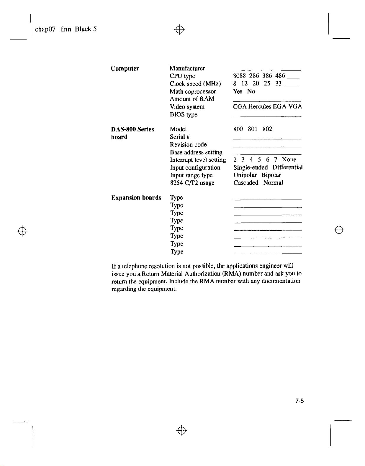
chap07-.frm Black 5
Computer
DAS-800 Series
board
Expansion boards
Manufacturer
CPU type
Clock speed (MHz)
Math coprocessor
Amount of RAM
Video system
BIOS type
Model
Serial #
Revision code
Base address setting
Interrupt level setting
Input configuration
Input range type
8254 C/r2 usage
8088 286
8 12 20
386 486p
25 33 _
Yes No
CGA Hercules EGA VGA
800 801 802
2 3 4
5 6 7 None
Single-ended Differential
Unipolar Bipolar
Cascaded Normal
If a telephone resolution is not possible, the applications engineer will
issue you a Return Material Authorization (RMA) number and ask you to
return the equipment. Include the RMA number with any documentation
regarding the equipment.
7-5
Page 91

chap07-.frm Black 6
When returning equipment for repair, include the following information:
. Your name, address, and telephone number.
. The invoice or order number and date of equipment purchase.
. A description of the problem or its symptoms,
. The RMA number on the outside of the package.
Repackage the equipment, using the original anti-static wrapping, if
possible, and handling it with ground protection. Ship the equipment to
the factory.
Note:
If you are submitting your equipment for repair under warranty,
you must include the invoice number and
date
of purchase.
7-6
Troubleshooting
Page 92

appx-a-.frm Black 1
Table A-l. DA!%800, DAS-801, and DA!%802 Specifications
Feature Attribute DAS-800 DAS-801 DAM02
-@
A
Specifications
Table A-l lists the specifications for the DAS-800, DAS-801, and
DAS-802 boards.
Specifications Specifications Specifications
Analog
Input
Number of channels
Input range
selection Not applicable Software
18 18
uronrammable
I
Software
wxrammable
A-l
Page 93
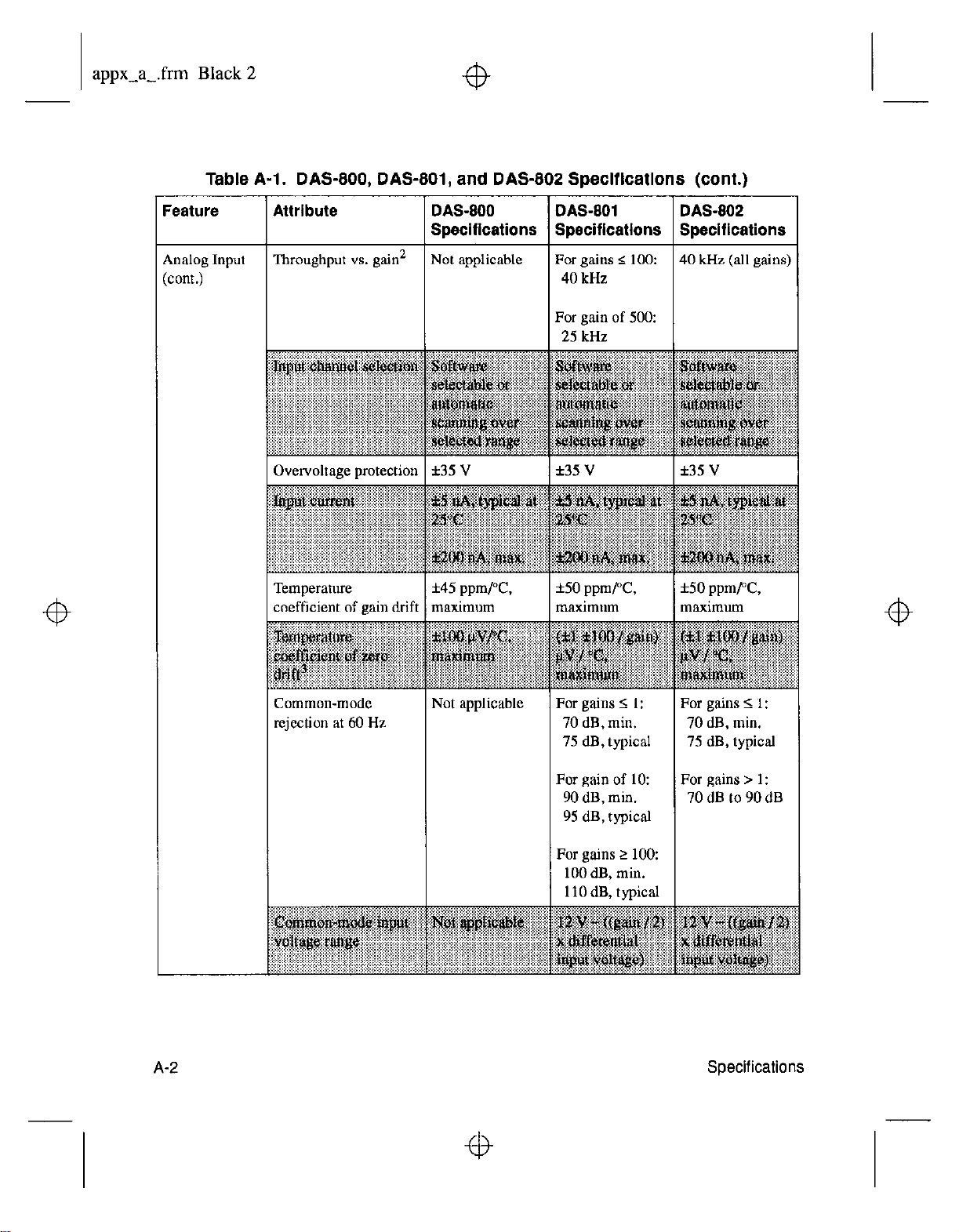
appx-a-.frm Black 2
Table A-l. DAS-800, DAS-801, and DAS-802 Specifications (cont.)
+b
:eature Attribute
\nalog Input ‘Ilxoughput vs. gain’
cont.)
coefficient of rain drift
DAS-800
Specifications
Not applicable For gains 5 100:
1 maximum
DAS-801
Swciflcatlons
40 kHz
For gain of 500:
25 kHz
f50
ppm/T,
maximum
3AS-802
Specifications
10 kHz (all gains)
i-50 ppmPC,
naximum
A-2
rejection at 60 Hz
For gains 2 1:
70 dB, min.
75 dB, typical
For gain of 10:
90 dB, min.
95 dB, typical
For gains 2 100:
100 dB, min.
llOdB, typical
For gains S 1:
70 dB, min.
75 dB, typical
For gains > 1:
70 dB to 90 dB
Specifications
Page 94
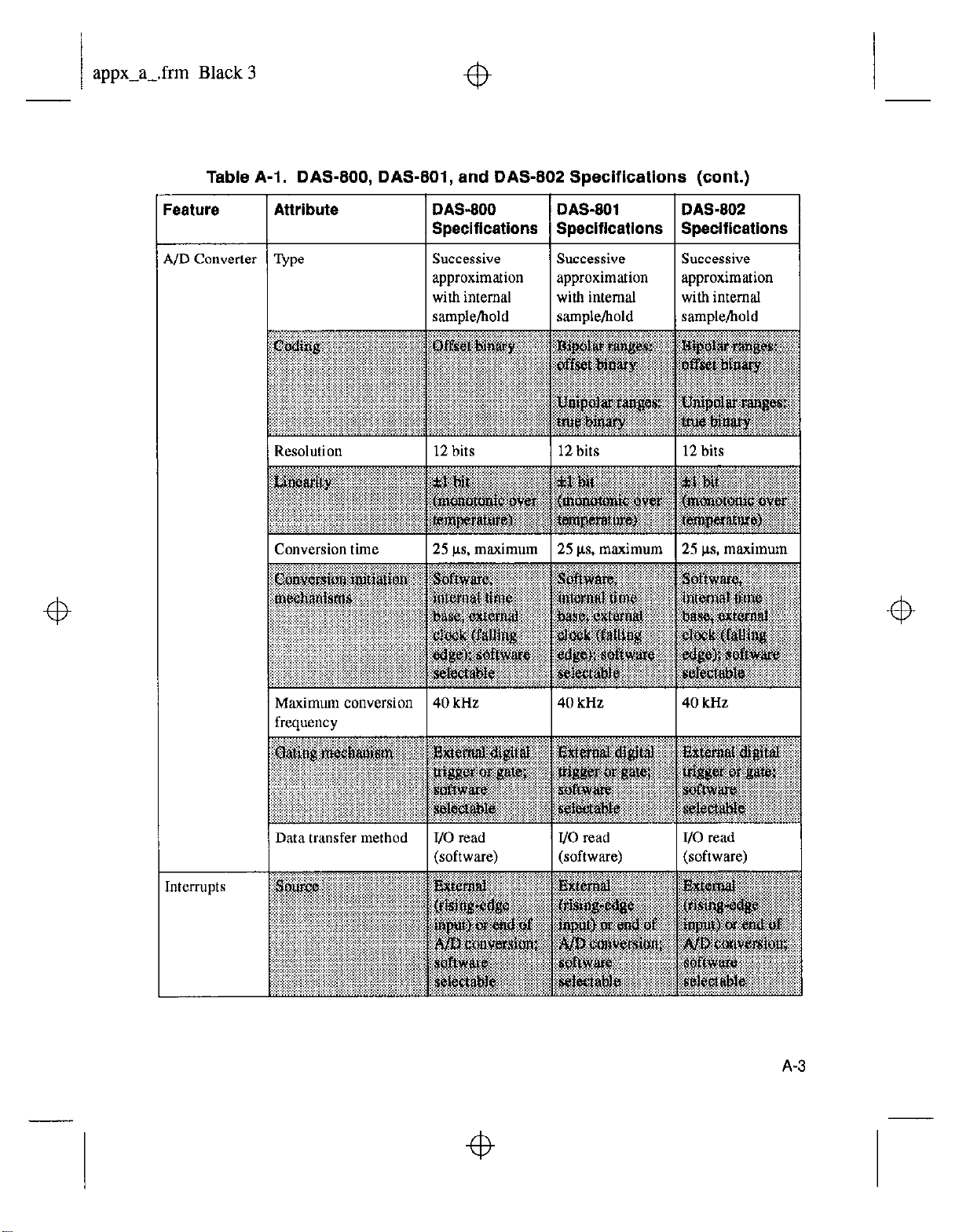
appx-a-.frm Black 3
Table A-l. DAS-800, DAS-801, and DA-S-802 Specifications (cont.)
+b
eature
Attribute DASIOO DAS-801 DAS-802
Specifications Specifications Specifications
Successive
approximation
with internal
samule/hold
Resolution
I Conversion time 125 us. maximum 125 us. maximum I25 us. maximum
1 12 bits 1 12 bits 1 12 bits
Successive
approximation
with internal
sample/hold
Successive
approximation
with internal
samtAe/bold
Maximum conversion 40 kHz
frequency
Data
transfer method l/O read IJO read JJO read
(software) (software) (software)
40
kHz
40
kHz
Page 95
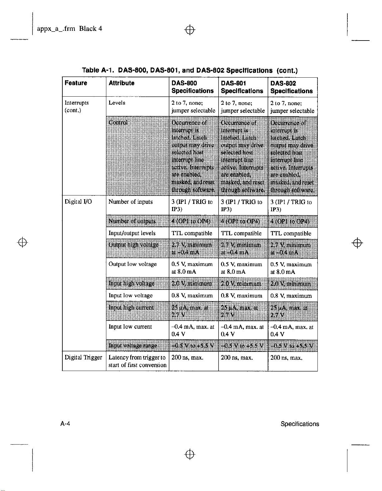
appx-a-.frm Black 4
Table A-l. DAS-800, DAS-801, and DAS-802 Specifications (cont.)
Feature Attribute DAS-800 DAS-801 DAS-802
Specifications Soeciflcations Soecifications
Interrupts
Levels
(cont.)
Digital I/O Number of inputs
“:‘,‘.‘.:/l> ....................... j: .. (,.,.,.,.(,,, :.~.~.:.:.~.~.~.~.:.:.;:.
.
Input/output levels
‘“““:.:“:.:“:i’“i’:.:‘:.:“-“lip:ir:i: .~.~.:.~:.:.:.~.:.:.:.~.:.:.~.:.:.~...:.:.~::~:~:~:::::~
:.:: .... :;;.:‘::::y:
~~~~~~u~~~~~~~ ,.~~~~~~~~~~~ ~~~~p~~~~~~ ~~~~~~~~II
..... pi .,.,
...............
. ..................... ..............
....
:E:~~~~~~
Output low voltage
2
to I, none;
2to1,none: 2
jumper selectable jumper selectable
3
(Ipl /TRIG to 3 UP1 /TRIG to
IP3) IP3)
TTL compatible
. ... I .... ‘F’.><i$ ........... (.... ......
............
TTL compatible ‘ITL compatible
:P(:~l:~;;:~:id:“:.:(“~~.:.~~:.:.:.:~:.:~ :i”:.:.<:e:.:.:.:F:.::,-:i?::. :/,:,:/,:.:/:.:,:,:,:/,
............ , ..~;il * ~I .... I
~~~~~~~~:~~ ::~~~~~:~~
...............
.( ..L.. ......... . ....
0.5 V. maximum 0.5 V, maximum
at 8.0 mA at 8.0 mA
to 7, none;
~iutnper selectable
3 (IPl /TRIG to
P3)
. ........... . ...........
. ..... I ., ................
>. ... . x.5, , I ,
0.5 V, maximum
at
8.0
mA
Input low voltage
Input low current
Digital Trigger Latency from trigger to
start of first conversion
A-4
IO.8 V, maximum IO.8 V, maximum
a.4
mA, max. at -0.4 mA, max. at
0.4
v
200 ns, max.
0.4
200
v
ns, max.
IO.8 V,maximum
-0.4 mA, max. at
0.4
v
200ns.max.
Page 96
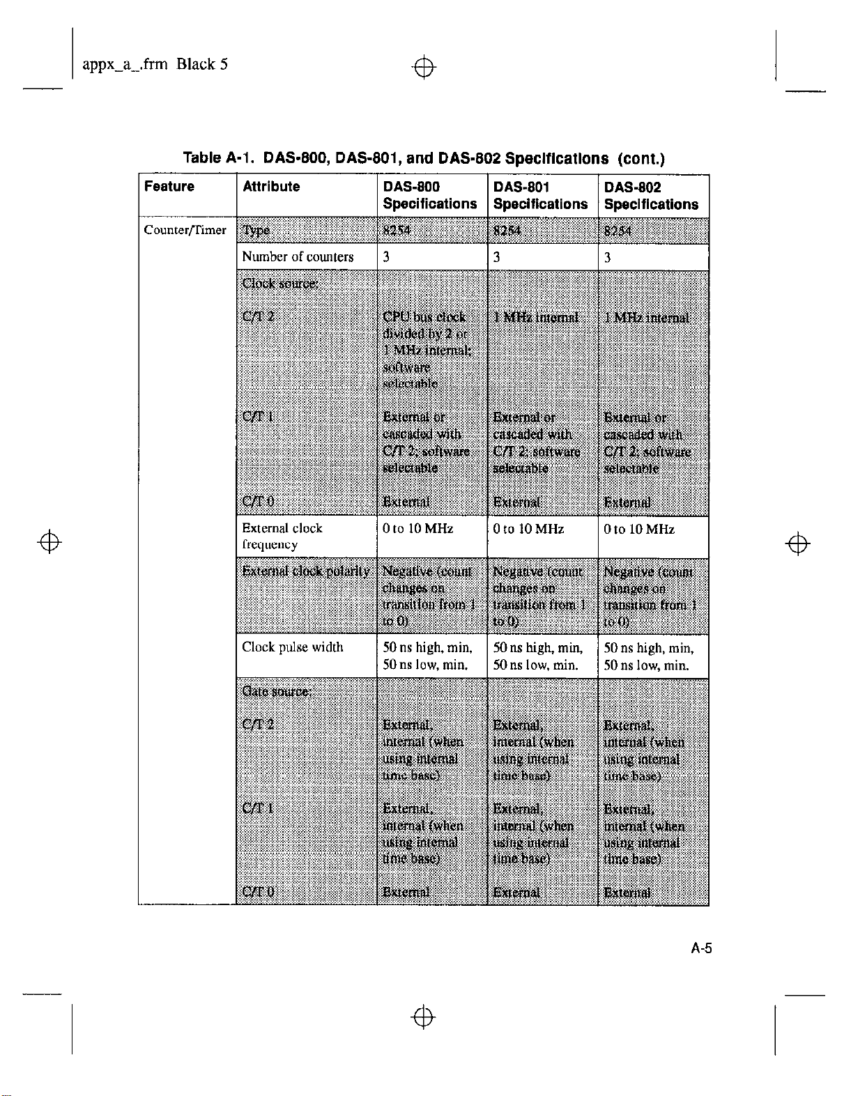
appx-a-.frm Black 5
Table A-l. DAS-800, DAS-801, and DAS-802 Specifications (cont.)
-@
:eature Attribute
I Number of counters I 3
External clock
frequency
DAS-800
Specifications Specifications SDecifications
DAS-801 DAS-802
I3 I3 I
0 to 10 MHz
IOtolOMHz IOto~iOiii~
Page 97
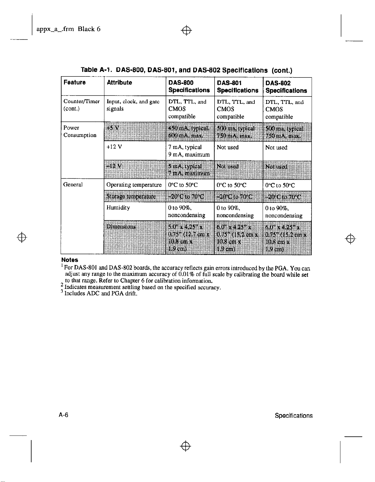
appx-a-.frm Black 6
Table A-l. DAS-800, DAS-801, and DAS-802 Specifications (cont.)
%ature
Attribute
DAS-800 I DAS-801 I DAS-~1
Specifications Specifications Specifications
Zounter/Timer Input, clock, and gate DTL, ‘I-I-L, and
cont.)
signals CMOS
compatible
7 mA, typical
9 mA, maximum
DTL, ITL, and DTL, ‘ITL, and
CMOS CMOS
compatible compatible
Not used Not used
I
Notes
’ For DAS-801 and DAS-802 boards, the accuracy reflects gain errors introduced by the PGA. You can
adjust any range to the maximum accuracy of 0.01% of full scale by calibrating the board while set
to that range. Refer to Chapter 6 for calibration information.
‘Indicates measurement settling based on the specified accuracy.
3 Includes ADC and PGA drift.
A-6
Specifications
Page 98
appx-b-.frm Black 1
Connector Pin Assignments
B
Figure B-l shows the main I/O connector and its pin assignments on a
DAS-800 board; Table B-l contains a more detailed description of the
pins. Figure B-2 shows the main I/O connector and its pin assignments on
a DAN301 or DAM02 board, Table B-2 contains a more detailed
description of the pins.
B-1
Page 99
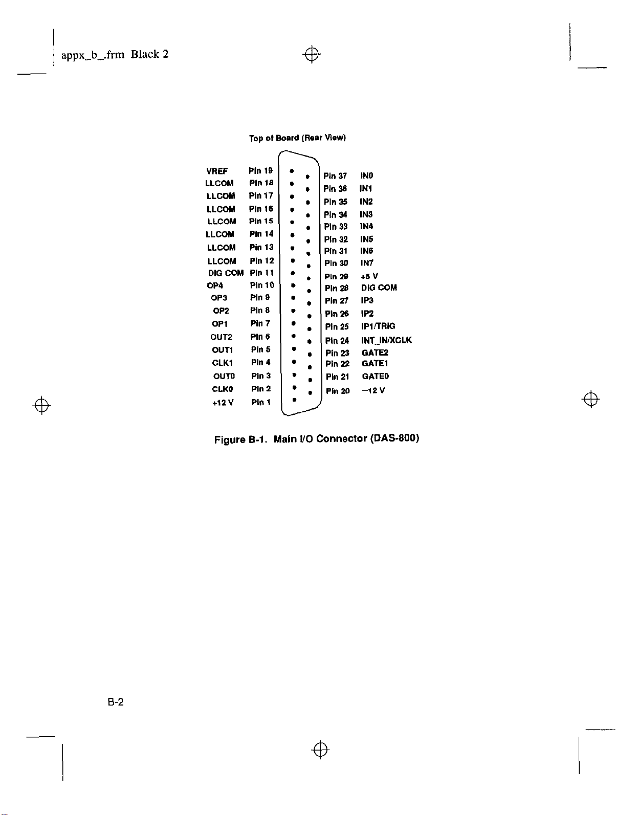
appx-b_.frm Black 2
Top of Board (Rear Vlewl
VAEF
Pin 19
l
LLCOM Pill19 . :
LLCOM
Pln17 .
LLCOM Pill 16 . :
LLCOM Pill 15 .
LLCOM
LLCOM
LLCOM
DIG COM Pin 11
OP4
Pin 14 . :
Pin 13 .
Pin 12 . .
. ,
Pin10 .
OP3 Pin 9 . :
OP2
OPl
OUT2 Pill 6
OUT1
CLKI
Ph 9 . ,
Pill 7 .
l
Pin 9
Pin 4
l
l
OUT0 Pill3 ’ ,
CLKO
Figure
Pin 2 ’ .
B-l. Main l/O
Ph 37 IN0
Pln 36 IN1
Pln 39 IN2
Pln 34 IN3
Pln 33 IN4
Pin 32 IN5
Ph 31 IN6
.
Pln30 IN7
ml29 +JV
Pin 29 DIG COM
Pin 27 IP3
Pln26 IPZ
PI” 29 IPl/TRIG
.
,
Pln 24 INTJNIXCLK
,
Pin 23 GATE2
Pin 22 GATE1
.
Ph 21 GATE0
pin20 -12v
Connector
(DAS-800)
B-2
Page 100

appx-b-.frm Black 3
Table S-1. Main I/O Connector Pin Assignments
for the DAS-BOO
B-3
 Loading...