

Page 1

DAS-4
Page 2
Part
DAS-4
Number:
24888
Last
Copyright
KEITHLEY
440
Taunton,
METRABrrUASYSTlDAC
Myles
Telephone
FAX
Revision
Edit:
Standish Boulevard
Massachusetts
A
July,
1987
@
1987
02780
5081880-3000
508/880-0179
Page 3
WARRANTY INFORMATION
All
products manufactured
and
worksmanship for a period of one year
purchaser.
Any
product that
option of Keithley MetrdByt'e,
by
Keithley MetraByte are warranted
is
found to be defective
be
repaired
products damaged by improper use.
hm
or
replaced.
the date
within
This
against
of
delivery to the ongind
the
warran@
warran@
defective materials
period
does
not
will,
apply to
at
the
Page 4

New Contact Information
Keithley Instruments, Inc.
28775 Aurora Road
Cleveland, OH 44139
Technical Support: 1-888-KEITHLEY
Monday – Friday 8:00 a.m. to 5:00 p.m (EST)
Fax: (440) 248-6168
Visit our website at http://www.keithley.com
Page 5
Table
of
Contents
...
Section 1 INTRODUCTION 1-
1.1
SUMMARY
Section 2 INSTALLATION 2- 1
2.1
BACKING UP
2.2
HARDWARE
Section 3 PROG€L"G
3.1
PROGRAMMING DAS-4
3.1.1
3.1.2 STARTING
3.1.3 READING
3.1.4
3.1.5
3.1.6
3.2 LOADING
"DAS4.BIN"
3.3 FORMAT OF
3.4 EXAMPLES
3.5 MODEO- INITIALIZE
3.6 MODE
3.7 MODE
MUX
3.8 MODE
3.9 MODE
MEMORY ON INTERRUPT
3.10
1
3.1
3.12 MODE
3.13 MODE
3.14 MODE
3.15 SUMMARY OF ERROR CODES
3.16 PROGRAMMING EXAMPLES
3.17 OTHER PROGRAMS AhD UTILITIES
3.18 ASSEMBLY LANGUAGE PROGRAMS AND CALLS
LANGUAGES
3.19 A NOTE ON EXECUTION TMES
3.20 MULTIPLE DAS-4's
I/O
THE
THE
SOME
.....................................................
MODE
MODE
OF DAS-4 FUNCTIONS
THE
DISK
INSTALLATION
.................................
........................
............................
..................................
ADDRESS MAP
THE
THE
DAS-4 STATUS REGISTER
DAS-4 CONTROL REGISTER
BASIC PROGRAMMING TIPS
THE
MACHINE LANGUAGE CALL ROUTINE
OF
DAS-4
A/D
CONVERTER
A/D
DATA
........................
....................
...........................
......................
....................
..................
................................................
THE
OF
CALL STATEMENT
THE
USE
OF
THE CALL ROUTINE 3-12
.....................
.........
..................................
1
.
SET MULTIPLEXER SCAN LIMITS
2
.
DO
ONE
A/D
CONVERSION
3
.
DO
N
AJD
CONVERSIONS DIRECT TO ARRAY
4
.
DO
N
A/D
CONVERSIONS
AND
AND
..............
INCREMENT
TRANSFER TO
..................................
5 . ANALOG TRIGGER FUNCTION
6
.
TRANSFER DATA FROM MEMORY TO ARRAY . 3-25
7 - READ
8
.
READ DIGITAL
9
.
WRITE DIGITAL OUTPUT
STATUS
..............................
INPUTS
IP1-3
OP1-4
................
.................
...............
.........................
FOR
THE DRIVER MODES
....................
IN
OTHER
.............................................
.
IN
ONE SYSTEM
COMPILED BASIC
....................
......
...
.
3-13
3-15
3-17
3-19
.
1
1-1
2-1
2-1
3-
1
3-1
3-2
3-2
3-3
3-3
3-4
3-5
3-6
3-9
3-21
3-23
3-27
3-28
3-29
3-30
3-31
3-31
3-32
3-32
3-33
.
Section 4 APPLICATIONS
4.1 CHANNEL INPUTS
4.2 MEASURING VOLTAGE
4.3 4-2OmA CURRENT LOOPS
4.4 THE REFERENCE
4.5 USING DIGITAL INPUT/OUTPUT
4.6 ADDING
MORE
......................................
.................................
.......................................
ANALOG INPUTS
................................
.........................
........................
1
4-
1
4-1
4-2
4-4
4-4
4-4
4-5
Page 6
4.7
INTERFACE TO TRANSDUCERS, THERMOCOUPLES ETC.
4.8 POWER OUTPUT
4.9 PRECAUTIONS IN USE - NOISE, GROUNDLOOPS
OVERLOADS
..............................................
FROM
THE
DAS-4 CONNECTOR
..........
AND
...
4-5
4-6
4-6
Section 5 CALIBRATION AND TEST
AND
5.1 CALIBRATION
5.2 SERVICE AND REPAIR
5.3
TECXNICALASSISTANCE
Appendix
A.1 MAINI/OCO"ECTOR
A.2 REAR
Amendix
AA
B.l POWER CONSUMPTION
B.2
B.3
B.4 SAMPLE
B.5
B.6
B.7
B.8 POWEROUTPUTS
B.9 GENERAL ENVIRONMENTAL
Appendix C STORAGE
A
CONNECTIONS A- 1
VIEW
B
SPECIFICATIONS
ANALOG
A/D
SPECIFICATION
OF
INPUT
HOLD
REFERENCE VOLTAGE
DIGITAL
INTERRUPTINPUT
I/O
...........................................
TEST
..................................
.................................
DAS-4
CONNECTOR
.................................
SPECIFICATIONS
....................................
AMPLIFIER..
OUTPUT
.....................................
......................................
OF
INTEGER VARIABLES
...............................
...............................
......................
.......................
............................
.........................
...........................
5- 1
5-1
5-1
5-1
A-1
A-3
--
B-
1
B-1
B-1
B-1
B-2
B-2
B-2
B-3
B-3
B-3
c-
.
1
..
11
Page 7
DAS-4
MANUAL
INTRODUCTION
Section
1
INTRODUCTION
1.1
MetraByte's
IBM
6300 series, Zenith, Compaq, PC's Limited, Tandon, Televideo etc. The
and can be
connector that projects through the rear of the computer. The following functions are
implemented on the
1.
2.
SUMMARY
PC-PC/XT-PC/AT & PS2 Model 30 P and other bus compatible computers e.g. A.T.&
DAS-4
fitted
is a 8 channel 8 bit hi h speed
in a
OF DAS-4
"half'
slot. All connections are made through a standard .37
FUNCTIONS.
A/D
converter and digital
I/O
DAS-4
board for the
board is
pin
DAS-4:-
An
8
channel, 8 bit successive approximation
+/-5
volts
input of each channel is
are single ended
volts and brief transients of several
when the computer power is off.
microseconds
30,000
7 bits of
port
channels/sec
TTL
of
3
bits.
with
max.)
and depending on the speed of the software driver, through puts of
are
digital
VO
a common ground and can withstand a continuous overload of
attainable.
are provided composed of one output port
with
a resolution of 0.03906 volts
hundred
A/D
AD
converter with samplehold. The full scale
volts. All inputs are fail safe
conversion hme is typically
(39.06
20
of
4
millivolts). Inputs
i.e.
open circuit
microseconds
bits and one input
5"
D
+/-30
T.
long
male
(30
up
to
1
precision
3.
reference. This output
A/D
Full
4.
An external interrupt input is provided that can select any of the
and allow user programmed interrupt routines to provide background data acquisition
interrupt driven control. The DAS-4 includes status and control registers that make intempt
handshaking a simple procedure. The
connected to any external
IBM
5.
The following utility software for
5-1/4" floppy
request)
1. A machine language
1.
Registered
P.C. bus power
rear connector. This makes for simple addition
conditioning circuits, expansion multiplexers etc.
:
-
110
channel functions via BASIC CALL. The I/O driver can select
trademarks
+5.OOv
Scale
disk
of
(+/-O.~V) reference voltage output is derived from the
can
trim
source/sink
pot.
5mA
and
is
the voltage
is
IBM
'ITL
(+5,
+12 & -12v) is provided along with
compatible with
I/O
driver (DAS4.BIN) for control of
International
Business
interrupt
compatible trigger source.
DAS-4
Machines
is provided
DOS
2.0 and higher revisions (3-1/2" media available on
Corporation.
input is positive edge triggered and may
all
other
of
user designed interfaces,
on
a double sided 360K PC-DOS format
AD,
and digital
A/D
converter
slightly adjustable
P.C. interrupt levels 2-7
YO
connections
input
by
the
or
be
on
the
signal
Page 8
INTRODUCTION
DAS-4
MANUAL
multiplexer channels, set scan limits, pexform
conversions, interrupt driven conversions and scans. The driver source
is
listing, DAS4.ASM,
2. Initial setup and installation aids.
3. Calibration and test programs.
4.
Electronic strip chart program.
5.
Slow
speed data logging program.
6. Other examples and demonstration programs.
The DAS-4 is simple, inexpensive and easy to use.
acquisition and control applications. 8 bits provides a span
corresponding to
than 1% bipolar resolution which is often adequate for many measurement, control and graphing
applications. The DAS-4 is hardware compatible with MetraByte's DAS-8 which provides
higher resolution through
To
extend the capabilities of DAS-4 the following expansion modules can
insulation displacement cable
SCREW "AL CONNECTOR BOARD
1.
connected to miniature screw terminal connectors. The digital
monitored
available for amplifiers, filters, and other user supplied circuits. The screw terminal
connector board is MetraByte part number STA-08.
-5
by
L.E.D.'s and a small bread board area with +/-12v & +5v power is
also provided
volts of input, and +127 corresponding to +4.96 volts.
the
use of a 12
to
the main
on
the disk.
bit
A/D.
37
pin
software commanded
It
is ideally suited to low precision data
D
VO
connector:-
-
All
VO
lines on the rear connector are
of
AD
255 bits with -128 bits
This
provides better
be
connected via flat
YO
port lines
are
EXPANSION MULTIPLEXER
2.
EXP-16 multiplexes 16 differential inputs to a single analog output suitable for
to
any
of
connection
cascadable so that up to
total
a
instrumentation amplifier
200
sensor is also included
directly connected
resolution of a
ISOLATION AMPLIFIER
3.
channels and
measuring off ground voltages
protecting input circuits. Up to 32
The ISO-4 also includes cold junction compensation and can be used
measurements. The
MetraByte also offers many optional software packages that can enhance
DAS-4. Their menu driven user interfaces eliminate programming and give fast results. Most
include the capability of generating
data and some also provide analytical capabilities as well. For a full description, see our catalog.
All of
ACQUIRE, LABTECH
STORAGE SCOPE,
of 128 channels. The expansion multiplexer board includes a low drift
or
1000
(other
12
can
our
software that works
the analog input channels of DAS-4. EXP-16 boards
8
EXP-16
with preselected switchable gains of
gains
can
for software compensation of thermocouples which can be
to
EXP-16, although the DAS-4 resolution will not provide the fine
bit
A/D
board when used for thermocouple measurements.
be
connected directly to DAS-4. This
ISO-4
provides gains ranging from
NOTEBOOK,
?TOOLS
AND
be
resistor programmed). A cold junction compensation
-
MetraByte's model ISO-4 provides 4 isolation amplifier
(500v
Lotus
with
DAS-8 will also
and CTOOLS.
INSTRUMENTATION AMPLIFIER - The
boards can be attached to a single
is
an
max. isolation) or eliminating ground loops or
IS04
expanders may
1-2-3 compatible data files, immediate graphing
work
UNKELSCOPE, UNKELSCOPE
be
connected to one DAS-4.
1
to
1000.
with DAS-4 and includes LABTECH
DAS-4
0.5,
1,
excellent accessory for
for
providing
2,
10,
thermocouple
the
ease
JR.,
50,
of
SNAPSHOT
are
100,
use of the
of
1-2
Page 9
-
DAS-4 MANUAL
Section
I
NSTAL LATlO
2.1
The utility software supplied with DAS-4 is
compatible
Model 30 drives, please contact MetraByte, it is available at no charge. It is advisable to make a
back up copy before using the software. For a direct back up, use the DOS DISKCOPY utility or
alternatively COPY
to a directory of your choice, the DAS-4 utility software is not copy protected.
you should misplace or damage the disk, please contact MetraByte for a free replacement.
BACKING
with
DOS
2.0
*.*
to a pre-formatted disk. For a hard
UP
THE DISK
thru
3.3 revisions.
If
you need a 3-1/2” disk compatible with the PS2
2
N
in
DOS 2.0 (360K DSDD) format which is
disk,
simply use COPY
INSTALLATION
*.*
to transfer
If
for any reason
2.2
DAS-4 utilizes 4 consecutive address locations in
used by internal
DAS-4’s
anywhere in the I.B.M.
space extends
be fully occupied.The PC AT’S
100-3FF), some
space also allows use of more than one DAS-4
for standard lBM devices are detailed below:-.
HARDWARE INSTALLATION
VO
and your other peripheral cards,
I/O
address can be set by the
PC decoded
fiom
decimal 512-1023 (Hex 200-3FF) which is much larger than is ever likely to
XT
compatibles
ADDRESS(Hex1 DEVICE ADDRESS(Hex1 DEVICE
000-
1
FF
200-20F
2 10-2 17
220-24F
278-27F
2FO-2F7
2F8-2FF
300-31F
320-32F
Internal system
Game
Expansion unit
Reserved
Reserved
LPT2:
COM2:
Prototype card
disk
Hard
BASE
I/O
VO
address space is larger and extends from 256-1023 (Hex
also
follow this expanded
ADDRESS D.I.P. switch to be on a 4 bit boundary
space. The PC and PC/XT’s expansion
in
378-37F
380-38C
380-389
3AO-3A9
3BO-3BF
3CO-3CF
3DO-3DF
3EO-3E7
3FO-3F7
3F8-3FF
VO
space. Some
so
to avoid conflict with these devices,
VO
a single computer. The reserved
I/O
addresses
space capability. Such a large
LPT1:
SDLC comm.
Binary comm.
Binarycomm.
Mono dsp/LPT
Reserved
Color graphics
Reserved
Floppy disk
COM1:
2
1
1
:
will
already be
UO
UO
address
addresses
the
This covers
1/0
peripherals e.g. special hard disk drives, special graphics boards, prototype cards etc. they
may
be making use
standard
of
IBM
I70
options (most compatibles are identical),
I/O
addresses not listed in the table above. Memory addressing is separate
but
if
you
have other
2-
1
Page 10
INSTALLATION
from
I/O addressing
computer. Usually, a
(Decimal
Hex
300-3
768
or
784). (Note
1F
address space and would conflict,
so
there is no possible conflict with any add-on memory that may
good
choices is to put the DAS-4 at base address Hex
if
you have an
IBM
prototype board plugged in,
&H330
or &H340 would be a good alternative
DAS-4
&H300
it
MANUAL
be
in
or
&€-I310
makes use of the
your
in
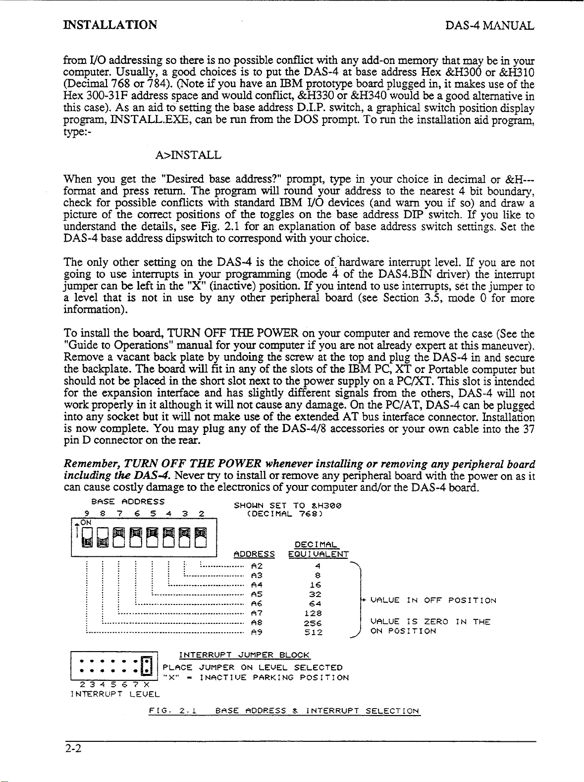
this case). As an aid to setting the base address D.I.P. switch, a graphical switch position display
program, INSTALL.EXE, can be run
the DOS prompt.
To
run
the installation aid program,
from
type:-
A>INSTALL
When you get the "Desired base address?" prompt,
will
format and press return. The program
check for possible conflicts with standard
the
picture of
understand
correct positions of the toggles
the
details, see Fig.
2.1
for an explanation of base address switch settings. Set the
round your address to the nearest 4 bit boundary,
IBM
YO
on
the base address DIP switch.
your choice in decimal
devices (and warn you
if
so)
or
&H---
and draw a
If
you like to
type
in
DAS-4 base address dipswitch to correspond with your choice.
The
only
other setting on the DAS-4 is the choice of-'hardware intempt level.
going to use interrupts in your progamming (mode
jumper can
a level that
be
left in the
is
not in use by any other peripheral board (see Section 3.5, mode
"X"
(inactive) position.
If
you intend to use interrupts, set the jumper to
4
of
the DAS4.BIN driver) the interrupt
If
you are not
0
for more
information).
To
install the
"Guide
to Operations" manual for your computer if you are not already expert at this maneuver).
Remove a vacant back plate by undoing the screw at the top and plug the DAS-4
the backplate. The board
should not
board,
be
placed in the short slot next to the power supply on a
TURN
will
OFF
fit
THE
POWER
in
any of the slots
on
your computer and remove the case (See the
of
the
IBM
PC,
in
XT
or Portable computer
PC/XT.
This slot is intended
and secure
but
for the expansion interface and has slightly different signals from t5e others, DAS-4 will not
work properly
into any socket but
is
now complete.
although
it
will
You
it
will
not cause any damage. On the PC/AT, DAS-4 can
not make use
of
the extended
AT
bus interface connector. Installation
be
plugged
may plug any of the DAS-4/8 accessories or your own cable into the
37
in
it
pin D connector on the rear.
Remember,
including
can cause costly damage
BASE ADDRESS
98765432 (DECIMAL
........
........
........................
.......
.......
.......
.............................
......
......
......
..................................
.....
.....
.....
.......................................
....
....
....
............................................
...
...
...
.................................................
..
..
..
......................................................
...........................................................
TURN
fhe
DAS-4.
OFF
Never
THE
POWER
try
to
install
to
the electronics
SHOUN
ADDRESS EQUIVALENT
whenever installing
or remove any peripheral
of
your computer and/or the DAS-4 board.
SET TO
A2
A3
A4
A5
A6
A?
A8
A9
hH300
768)
DEC
16
128
256
512
I
MAL
4
8
or
removing any peripheral board
board
VALUE
VALUE
ON
POSITION
with the power on as it
IN
OFF
POSITION
IS
ZERO
IN
THE
234
I
NTERRVPT
2-2
567X
LEVEL
FIG.
INTERRUPT
PLFICE
"
X"
-
2.1
JUMPER
JUMPER ON
I
NACT
I
VE
6ASE
~ICIDRESS
BLOCK
LEVEL SELECTED
PARK
I
NG
POS
I
TI
d
iNTERRUPT SELECTION
ON
Page 11
PROGRAMMING
Section
3
PROGRAMMING
3.1
At
-
BASIC these
level languages have equivalent instructions
functions
demanding, this can require many lines
data format and architecture
routine "DAS4.BIN" is included
BASIC by a single line CALL statement and covers the majority of common operating modes.
The various modes of
check data, and perform frequently
performs
read data and increment the multiplexer.
Using the DAS4.BIN driver saves a lot of programming time and has some other benefits as
well. For instance, the driver supports data collection on interrupt from an external source. Note
that BASIC has no intempt processing functions and
using these methods is only available using
PROGRAMMING DAS-4
the lowest level, DAS-4 can
are
the
INP
@)
usually
a
involves formatting data and dealing with absolute
the
CALL routine select all the functions
sequence of operations required to perform an
be
and
OUT
of
the DAS-4.
in
used
programmed
of
the DAS-4 software package. This may
using
X,Y
functions. Assembly language and most other high
(IN
code and necessitates an understanding
To
simplify program generation, a special
sequences
the
of
CALL routine.
YO
input and output instructions. In
AL,DX and
instructions. An example is Mode 2 which
so
called "background" data collection
OUT
of
MI
conversion, check
DX,AL). Use of these
VO
addresses. Although not
the DAS-4, format and error
of
be
accessed
the devices,
A/D
I/O
driver
from
status,
INP
Both methods of programming using
same result, and
the
CALL routine much simpler to implement. If you need
non-sequential channels, special interrupt routines etc. you can modify the DAS4.BIN driver to
your requirements. The fully commented assembly source is supplied on the utility
(DAS4.ASM) and can
is
a good starting point for assembly language programmers who wish to modify
driver. For the steps involved in generating a BLOADable DAS4.BIN
instructions
prompt).
in
you
are free to choose either although usually
be
re-assembled using the Microsoft Macro-Assembler (any version) and
the
file HOWTO.BIN
and OUT functions and the CALL routine achieve the
the
BASIC proFammer will find
to
perform specialized scans such
the
file,
follow the
file
on the disk (enter
TYPE
HOWTO.BIN after the DOS
as
disk
standard
3-
1
Page 12
PROGRAMMING
DAS-4 MANUAL
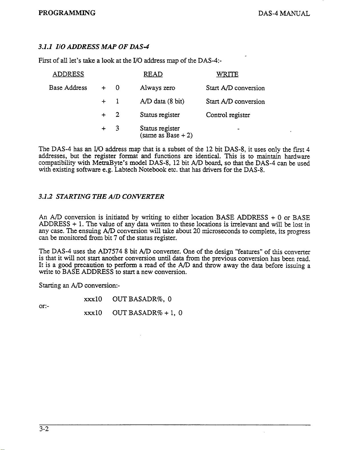
3.1.1
IIO
ADDRESS
First
of
all let’s
take
ADDRESS
Base Address
The
DAS-4
addresses, but the register format and functions are identical.
compatibility with MetrdByte’s model
with existing software e.g. Labtech Notebook etc. that has drivers for the
3.1.2
STARTING
has
MAP
a look at the
+
+1
+2
+3
an
VO
address map that is a subset of the
THE
AID CONVERTER
OF
0
DAS-4
VO
address map
READ
Always zero
A/D
data
Status register Control register
Status register
(same as Base
of
the
DAS-4:-
(8
bit) Start
+
2)
WRITE
Start
12
bit
AD
AD
DAS-8,
This
DAS-8,
12
bit
AJD
board,
so
conversion
conversion
that the
it uses only the fust
is to maintain hardware
DAS-4
can
be
4
used
DAS-8.
An A/D
ADDRESS
any case. The ensuing
can
The
is that
It
is a good precaution
write
Starting
conversion is initiated by writing to either location
+
1.
The value of any data written to these locations
be
monitored
DAS-4
it
will
to
BASE ADDRESS
an
A/D
from
uses the
not
start
conversion:-
AD7574 8
xxxl0
or:-
xxxl0
A/D
conversion will take about
bit
7
of
the status register.
bit
A/D
converter. One of the design “features” of this converter
another conversion until data
to
perform a read of the
to
start a new conversion.
OUTBASADR%,
OUTBASADR%
+
0
1,
AD
0
BASE
20
microseconds to complete, its progress
from
the
previous conversion has been read.
and throw away the data before issuing a
ADDRESS
is
irrelevant and will
+
0
or
be
BASE
lost
in
3-2
Page 13
DAS-4
MANUAL
PROGRAMMING
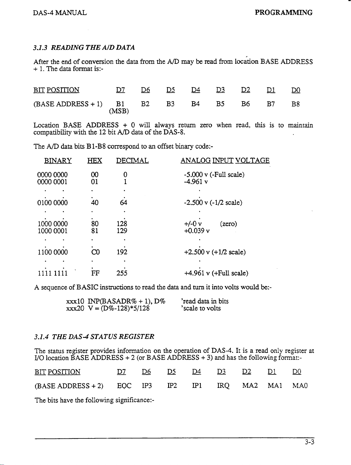
3.1.3
READING
After the end
+
1.
The data format is:-
-
BIT POSITION
(BASE ADDRESS + 1) B1 B2 B3 B4 B5 B6 B7 B8
Location
compatibility
The
BINARY
0000
0000
0100
BASE ADDRESS + 0
A/D
data
OOOO
0001
0000
THE
AID DATA
of
conversion the data
-
D7
(MSB)
with
the
12
bit
A/D
bits
B 1-B8
HEX
correspond to
DECIMAL ANALOG
00
01
40
0
1
64
from
the
A/D
may
be
read
from
location
-
D6
will always return zero when read, this is to maintain
data
of
-
D5
the
DAS-8.
an
offset binary code:-
_.
D4
-5.000
-4.961
-2.500 v (-1/2
-
D3
INPUT
v
(-Full
v
D2
VOLTAGE
scale)
scale)
BASE ADDRESS
D1
DO
1000
0000
1000
0001
1
loo
0060
iiii
iiii
A
sequence of
xxxl0 INP(BASADR% + l),
XXX~O
3.1.4
The
I/O
BIT POSITION
THE DAS-4 STATUS
status register provides information on the operation of
location
(BASE ADDRESS
BASE ADDRESS
80
81
CO
*
FF
BASIC
V = (D%-128)*5/128
+
2) EQC
128
129
192
255
instructions to read the data and
D%
REGISTER
+
2
(or
BASE ADDRESS + 3)
-
D7
-
D6
IP3
-
D5
IP2
+/-0
v (zero)
4.039
+2.560
~4.961
'read data
'scale to volts
v
v
v
turn
it into volts
-
D4
LP1
(+1/2
(+Full
in
DAS-4.
and
bits
has
-
D3
IRQ
scale)
scale)
would
It is a read only register at
the
D2.
34A2 MA1
be:-
following format:-
D1
-
DO
MA0
The bits have the following significance:-
Page 14
PROGRAMMING
DAS-4
MANUAL
EOC:
IP3
-
IP1:
IRQ:
MA2-MAO:
End of Conversion.
A/D
is busy performing a conversion. Data
should not
invalid. Wait for the
sigmfying valid data available.
These bits correspond to the three
port lines
for any
After generation of an interrupt to the processor
IRQ
is
(0)
low
provides a means
"handshaking"
These bits provide the current analog
multiplexer channel address as follows:-
MA2
be
IP3,
digital
set to logic high
by a write
MA1 MA0 CHANNEL
0
0
1
1
If
EOC
is
high
(Logic
read
in
this
condition
EOC
to
return
digital
IP2 and IP1. They may
input data.
(1).
It
is reset
to
DAS-4
the control
of
acknowledging or
interrupts.
register.
0
1
0
1
as
to
it
1)
will
logic
input
be
used
to
logic
This
the
be
0.
0 0
0
1
1
1
0
1
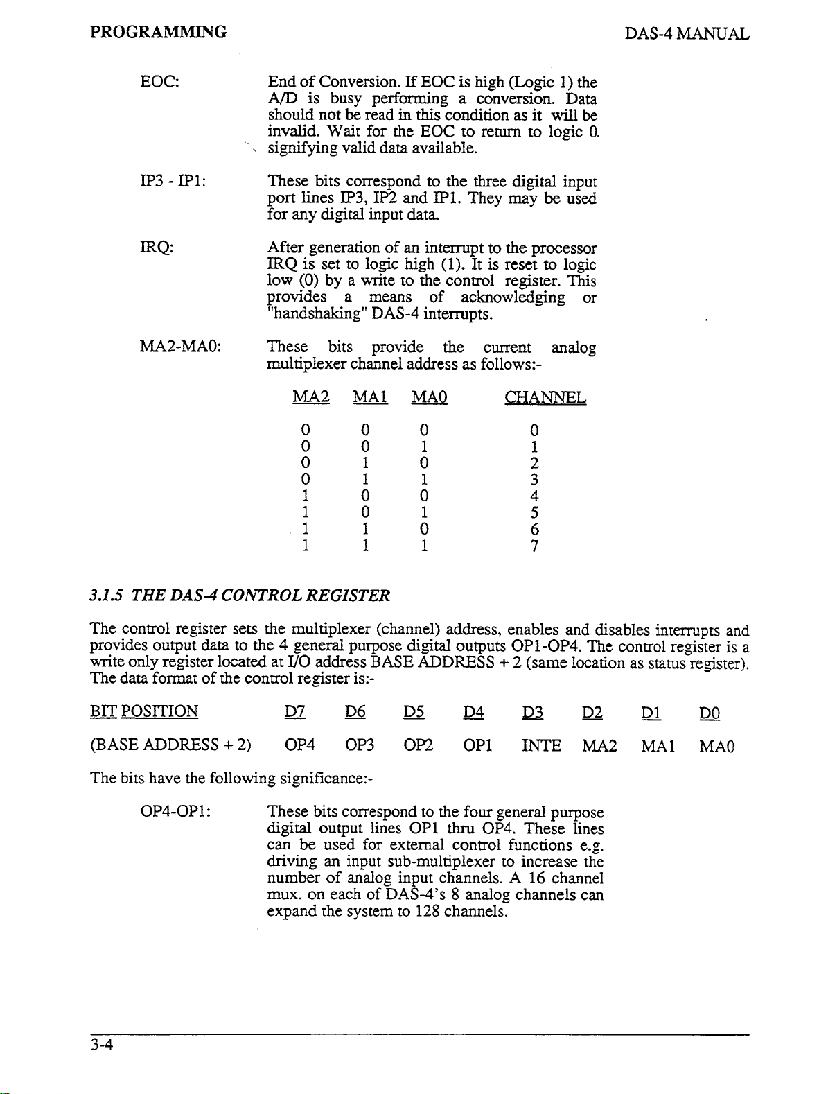
3.1.5
The control register sets the multiplexer (channel) address, enables and disables intempts and
provides output data to the
write only register located at
The data format of the control register is:-
-
BIT POSITION
(BASEADDRESS+2)
The bits have the following significance:-
THE
DAS-4 CONTROL
OP4-OP1: These bits correspond to the four general purpose
REGISTER
4
general purpose digital outputs OP1-OP4. The control register is a
UO
address
-
D7
OP4 OP3 OP2 OP1
digital output lines OP1 thru
can be used for external control functions e.g.
driving an input sub-multiplexer to increase the
number
mux.
expand the system to 128 channels.
of
on
BASE ADDRESS + 2 (same location as
-
D6
analog input channels. A
each
-
D5
of
DAS-4's 8 analog channels can
-
D4
OP4.
-
D3
INTE
These lines
16
channel
status
D2-
MA2
D1
MA1
register).
DO
MA0
3-4
Page 15
DAS-4
MANUAL
PROGRAMMING
INTE:
MA2-MAO:
DAS-4
of the selected
INTE
INTE
,
input (pin
level and are positive edge triggered.
programmer's responsibility to set up an
interrupt handling routine, intempt vectors and
initialize the
IBM
register will clear the
register.
These bits select the current analog multiplexer
channel address as follows:-
generated interrupts are enabled onto
IBM
P.C.
interrupt levels
=
1
(logic high). Interrupts are disabled if
=
0
P.C.
MA2
(logic low). Interrupts
24)
are passed through to the selected
8259
processor board. Writing to the control
interrupt controller
IRQ
MA1
MA0
from
bit
of
CKANNEL
the
It
the
2-7
INT.IN
is the
on
any
if
the
status
The multiplexer channel address
One further note about the control register. During power up
line of the IBM
interrupts are disabled, sets
address to zero.
3.1.6
programming, but may
SOME
Some BASIC commands which
Data read
ANDed
until a non-zero result is obtained. This is an excellent way
program
This command
with
checks the timer
P.C.
is
asserted, the DAS-4 control register is cleared. This insures that
BASIC
a pseudo-interrupt. After execution
PROGRAMMING
be
useful with
WAIT
with
wait
ON
port, n[,m]
at
the port
"n".
If
until some desired external condition is attained.
TIMER
is
only available in DOS
to
can
be
determined at any time by reading the status register.
digital
outputs
OP1-4
to zero and sets the multiplexer channel
TIPS
you
may not have used frequently in the come
DAS-4
is
exclusive-or'ed (XORed) with integer expression "m" and
the result is zero, BASIC
(n)
GOSUB
see
if
the condition >n
line
are:-
2.0
loops
and above. In effect
of
each BASIC statement, BASIC
(
1
<
n
<
86,400
of
the
IBM
back and tests
of
seconds) is satisfied.
P.C.
the
making
it
provides
when the
of
port again
your
you
If
RESET
DAS-4
ordinary
3-5
Page 16
PROGRAMMTNG
it
is, control passes
polling of the timer
TIMER ON
Trapping is disabled by:-
to
the subroutine, otherwise the next line
is
called trapping and is activated by:-
is
executed.
DAS-4
MANUAL
This
3.2
TIMER
Note that trapping only occws while your BASIC program is executing (unlike a
true interrupt) and can
execution time.
is a convenient way
If
you
wish to program an
than the more powerful CALL routine, the following sequence should
followed:-
xxxl0
xxx20
xxx30 D%=INP(BASADR%+l) 'read
Note that looping while the
in interpreted BASIC
conversion time of
compiled using the BASIC COMPILER, the execution time is reduced to a point
where the status test
line
xxx30.
OUT
IF
LOADING THE
OFF
be
slightly delayed by statements that require a
If
you
need
to
sample
to
do
it.
A/D
BASADR%
INP(BASADR%+2)>=&H80
as
20
of
+1,0
A/D
the interpreter execution time greatly exceeds the
microseconds. However,
line
xxx20
at
long intervals the
conversion using BASIC
converter is still busy (line.
is essential
MACHINE
ON
TIMER command
INP
and
OUT
'start
A/D
conversion
GOT0
xxx20 'status test loop
A/D
data
xxx20)
if
the program is subsequently
to
avoid returning enoneous data in
is not required
LANGUAGE CALL
lot
of
rather
be
A/D
ROUTlN
As
the previous simple example
tedious to implement although a lot of the required programming could
subroutines. Use
circumvents the execution time delays of interpreted or compiled BASIC, and
background data collection using intempts.
In
order
You
must avoid loading
BASIC (watch out for BASICA.EXE if you
Disk".
work and
damage will result, but to get things going again you
seconds before turning
in
general and would apply to loading any CALL or
information provided
When you load the DAS4.BIN CALL routine, you have two options depending on the size of
your
If
them,
available memory. Due to the design of Microsoft Basic, the maximum memory se,ment
E
"DAS4.
of
the CALL routine described in the
to
make use of the CALL routine "DASABIN",
you do interfere with another program's use of memory, the CALL routine will not
most
likely your PC
on
SAVE
them
before
in
the "I.B.M. BASIC MANUAL".
BI
N"
shows,
it
over any part of memory that is being used by another program e.g.
will
again).
you
direct
do
strange things for a second or two and then hang up
Here
is
run
them!
UO
using BASIC
are
using
some
advice,
Note that the information given
GW
will
have to turn off power and wait a few
when
USR
INP
and
this
section avoids these problems,
it
must first
BASIC) print spoolers or
you
write programs with
routine and supplements the limited
OUT
can
be
loaded into memory.
in
be
somewhat
be
handled
also
permits
"RAM-
CALLS
this section is
(No
in
3-6
Page 17
DAS-4
MANUAL
PROGRAMMING
that BASIC
following message on power up
BASIC
The exact number of "Bytes free" varies with the version of BASIC(A) and DOS but is usually
greater
available. When the number of memory bytes free
your PC's memory is already
than
its possible
routine by further forced contraction of the BASIC workspace and loading the routine at the end
of
the newly defined workspace. DAS4.BIN will occupy about 1852 bytes but to keep things
simple, let's clear a
Step 1 is
DOS:-
Note the number
return
is
able to use is
The
Version D1.10 Copyright
61807 Bytes free
than
60000
bytes
64K
maximum workspace.
2K
to
work
out
how much memory BASIC is able
A>
BASIC(A)
of
bytes free
to
DOS and this time load BASIC(A) with the optional
A> BASIC(A)
64K
bytes.
or
from DOS by entering A> BASIC(A)
IBM
Personal Computer Basic
if
an
excess of memory over and above what BASIC can use is
fully
utilized and BASIC
(2048 byte) space for
in
BASIC's greeting messages. Next
/M:
WS
If
where
BASIC
IBM
If
this
it
WS
is
is
using
Corp. 1981,1982
is
less than
is
is the case, you
a number (not a variable)
its
maximum
60000,
adjusting to
will
to
use. First just load BASIC(A) from
do
/M
parameter:-
64K
you
will
:-
this is an indication that
this
condition by using less
have to load the CALL
a SYSTEM command to
get the
Try
setting the WS (workspace) parameter
free in the greeting message. The objective is to determine the workspace that must
to
reduce the bytes free by at least 2048 bytes. Once
BASIC(A) by specifying this workspace or include a CLEAR command right at the beginning of
your program e.g.:-
xxxl0 CLEAR,
Next, we need
Microsoft derived BASIC, this can be found
&W11 and &=lo which hold the current BASIC segment which we can call SG.
determined as follows:-
The segment address at which we can now load
the working space i.e.:-
to
know what segment BASIC is occupying in memory.
xxx20 DEF SEG
xxx30
xxx40
SG
SG = WS/16 + SG
WS
=
0
=
256*PEEK(&H511) + PEEK(&KS10)
to
30000 or 4oooO and then note the number of bytes
be
specified
this
is determined
from
the contents
'define current segment
before reading absolute
addresses 0000:0510
the
CALL routine will simply
'remember segment addresses
on
are
16 bit boundaries
of
absolute memory locations
=
&
0000:0511
0000
you
can either load
In
all
versions of
SG
be
at
can
the
be
end of
The routine can now
xxx50
xxx60 BLOAD "DAS4.BINtt,0
be
loaded as follows:-
DEF
SEG
=
SG
'loads routine at
SG:0000
3-7
Page 18
PROGRAMMING
DAS-4
MANUAL
A BLOAD
CALL
the
parameters
Note that
the starting address of the
preceding
to associate with the device and would distinguish it
might be
(FORTRAN, PASCAL
the name of the external routine that the linker will
compilation.
3.19).
Returning
defined by the last
routine is located.
somewhere in a program before entering the
your
program,
DEF
duplication. This precaution can save a
computer!
must
be
used as we are loading a binary (machine language) program. Once loaded,
can
be
entered
MD%,
D%, FLAG%
xxx70
xxx80
xxx90
in
interpreted
DEF SEG
in
the same program.
statement. We have chosen
DAS4.0BJ
to interpreted
DEF
Be
as
many times
prior
to
the
as
CALL
DEF SEG = SG
DAS4
CALL DAS4
Microsoft
=
0
@ID%,
D%(O), FLAG%)
BASIC, DAS4
CALL
etc.) the significance of
is supplied on the software disk for this purpose (see Sections 3.18
BASIC, DAS4
SEG
careful that
routine from the current segment
In
compiled
statement that tells your
you
BASIC,
is the offset (actually zero)
do not inadvertently redefine the current segment
CALL.
it
is good practice to immediately precede the
SEG
statement (the same one you preceded your
lot
of wasted time and frustration from crashing your
needed
DAS4
in
sequence as follows:-
is a variable that specifies the memory offset
as
from
Quick Basic or other compiled languages
DAS4
in the
If
you
the program after initializing the call
of
as
defined
a
name,
any other
be
BASIC
are
BLOAD
as
it
makes
CALLS
CALL
CALL
is different.
looking for when linking after
from
interpreter where the
using
DEF SEG
statement
with) even at
in
the most recent
CALL DAS4
to other routines that
In
this case,
the current segment as
easy
it
is
&
CALL
in
other parts
by
the appropriate
the
cost
of
of
Another important detail to understand is that
BASIC
available
end up loading
hang up the computer.
and later load
compensating reduction in the workspace
memory is limited, setting up a workspace that is a considerable amount less than what is
available
than the
completely into
DOS
loads
contraction
memory
happen on a machine
the workspace
little on
doing.
loading and using the
use
The
have plenty
routine outside the
beginning.
working area up whereas we must
memory down.
our
BASIC
is
a simple precaution. Another precaution in this regard occurs
IBM
P.C.)
that do not contain most of
RAM
and the
from
To
as
a "front end" to your own programs.
second method
BASIC
the top of memory down. The
of
the
minus
the
that used
is
the only way
complex side, but like
further assist you,
of
memory (generally
BASIC
For
example we might choose
If
we attempt
routine over the end
Be
careful this does not happen inadvertently
with
DEBUG
in
the
form
of a
program space load from the bottom of memory up
BASIC
with
of
program space will automatically take place as
by
DOS
and
less than
of
loading the
run
and list the file
CALL
loading the driver
routine and ready made loading and ininalizing code that
256K
workspace.
or some other memory resident program without making a
BASICA.COM
128K
all
In
CLEAR
set
aside space for
to
CLEAR
of the
BASIC
(WS)
the
free
BASICA.EXE
of memory
CALL
things they
is
somewhat simpler
or more) and you have the
this case choose a segment that has
&H6000
sets working space from the bottom
our
subroutine from the top
more space than
program, data space and stack and will
declaration in
BASIC
memory ends up
in
ROM.
and a
BASICA.EXE
becomes less
in
which case further forced contraction
routine. These considerations all sound a
are
not once you understand what you are
EXOO.BAS.
which
is
at 384K. Then proceed as follows:-
is
actually available, we will
if
you
are
memory limited
the
CLEAR
These machines load
in
than
This gives you an examples
to
follow and applies when you
luxury
statement. When
on
computers (other
file.
BASICA.COM,
and
BASICA.EXE
the
middle and some
soon
as the total
MK.
This
can
of loading the
2K
bytes clear at its
of
the
of
BASIC
easily
of
of
you
can
CALL
3-8
xxxl0
DEF
SEG
=
SrH6000
'Sets
up
load segment
Page 19
DAS-4
MANUAL
PROGRAMMING
xxx20
-30 DAS4
-40
xxxxx
xxxyy
xxxzz
An
example of
workspace,
DEF
locations. Usually
obliteration of some of the routine code and a
computer hangs up, and
floor
large amounts of memory may
memory than the example above.
resident space in memory
SEG statements in
again. Note that memory resident programs such
in
UP.
be
memory for additional programs such as
BLOAD "DAS4.BIN",O
=
0
DIM D%(3)
I111
Ill1
llll
DEF SEG
CALL DAS4
etc.
this
approach is contained
sure you really do have an unused
any
=
&H6000
(MD%,
EXO.BAS
clash with another program's use of the same memory
and experiment
'Loads at
D%(O),
in
file
failure
the
only cure
run
than
earlier versions and
is
to
switch
out of space or require loading the
Also
higher revisions of
6000:oooO
FLAG%)
EXO.BAS.
2K
of
with
Before
memory at
loading the
you
try
384K.
CALL
loading outside the
You
can change the
routine at other
results
to exit and return from the routine. The
off,
wait a few seconds
as
Borland's Sidekick will raise the loading
BASIC(A).
may
require
DOS
In
this case even machines with
with
loading the
and
turn
on the power
DASABIN
additional features use more
CALL
even higher in
routine higher
in
3.3
If
the
the
subroutine is located. The
As
memory as defined
defme the current segment to correspond with the starting address of the
this offset is always zero and
The
the addresses
The
BASIC's
must be met:-
1.
FORMAT
you
are
new to using
CALL
CALL,
explained
three
CALL
transfers execution to the machine language (binary) driver routine. Prior to entering
variables within brackets are known
routine unloads these pointers from the stack and uses them to locate the variables
data space
The
CALL
knows
from
OF
THE CALL STATEMENT
CALL
the
DEF SEG
xxxxx
the order
CALL DAS4 (MD%, D%(O), FLAG%)
in
the previous section,
ir!
the last
of
the Variables (pointers) are passed in the sequence written
so
data can be exchanged with them. Three important format requirements
parameters are referenced by position. The subroutine
nothing of the names of
of
statements, this explanation
=
SG
statement sets
CALL
statement for the
DAS4
DEF
SEG
statement.
DAS4
their pointers
=
0.
the
variables, just their locations
on
the stack.
may
assist you in understanding how
the
segment address at which the
DAS4.BIN
is the address offset from the current segment
In
as
the
CALL
driver must
all
of
our
parameters. On executing
examples, we have chosen to
be
of
CALL
to
CALL
the form:-
of
routine, therefore
the
CALL,
BASIC's
stack.
in
If
you
xxxxx
write:-
CALL DAS4
(D%(O),
MD%,
FLAG%)
3-9
Page 20

PROGRAmG
you
will
mix
up the CALL routine, since it
as the mode number, the mode
2.
3.
parameters
(mode, data, errors)
The CALL routine expects its parameters
variables and
assumption.
double precision) variable in the CALL pmeters, the routine
will
not function correctly.
CALL on the variable type,
computer!
You
parameter list brackets
must
cannot
will
If
you slip
will
interpret
MD%
always
perform any arithmetic functions within the
write
up
of
be
written
and read
and use a non-integer (real single
so
the
in
No
error checking
be
careful since you may crash the
CALL statement e.g:-
as
the
the
correct order:-
to
be
to
the variables on
is
data
D%(O)
etc..
integer
done
in
The
type
this
or
the
DAS-4
MANUAL
CALL DAS4
is illegal and will produce a syntax error.
4.
Apart from these restrictions, you can name the integer variables what you want, the names in
the examples are just convenient mnemonics. Strictly, you should declare the variables before
executing the CALL.
but array variables cannot
to
routine require multiple items
as the data variable
initial element
You can use some elegant techniques with
or output a whole series of data in a
a two or more dimension array, for example:-
You
cannot use constants
statement. The following is illegal:-
CALL DAS4
This must be programmed as:-
XXxlO
xxx20
xxx30 CALL DAS4 (MD%, D%(O), FLAG%)
pass data
MD%
D%(O)
COKCX~~Y
(MD%
(7,2,
=7
=
If
you do not, the simple variables will
be
if
used as a CALL parameter. Many modes of the DAS4.BIN CALL
so
that the CALL routine can locate the whole
+
2,
D%(O)
for
any of the parameters in the CALL
FLAG%)
2
dimensioned by default
of
data
to
FOR.
*
8,
FLAG%)
be
passed in an array. For this reason, D%(O) is specified
the
CALL parameters. Let’s say we wanted to record
.
.
NEXT loop.
and
must
be
declared by default on execution,
be
dimensioned before the CALL
array
from the position
You
can dimension
your
of
D% array
its
as
xxx00 DIM D%(4,100)
SEG
=
xxxl0 DEF
xxx20 FOR
xxx30 CALL DAS4
xxx40
Likewise any of the other CALL parameters may
can name any number
dimension
unchanged and for example could be used
arrays
I = 0
NEXT
with
more elements
SG
to
100
(MD%,
D%(O,I), FLAG%)
I
of
different integer data arrays for output and input. It is
than
will
for
tagging data with time, date or other information.
be
integer array variables
be
used
by the CALL, unused elements
if
required, and you
O.K.
will
to
be
Page 21

DAS-4
MANUAL
PROGRAMMING
MetraByte
board.
CALLS
functions or modes use
allow for
only use
each CALL
for the whole program and save a
BLOADing the DAS4.BIN driver (see EXO-BAS) proceed as follows (this program logs
channels
has
chosen
This
makes the CALL structure
with
variable offsets
the
needs of modes
a
few elements. In the interests of clarity,
written
2
-
5
to
disk
xxl00 DIM D%(3)
XXllO
xx120 D%(O) = &H300 : D%(1)
xx130 GOSUB 10000 'initialize
xx140
xx150 D%(O)
xx160 GOSUB
xx170 OPEN "MYF'ILE.DATt FOR OUTPUT AS
xx180 TNOW = TIMER 'get system time (in seconds)
XX190
xx200 GOSUB
xx210
xx220
xx230
MD%
MD%
MD%
PRINT
IF
IF
to
use the Same CALL structure for selecting
and
number of parameters. One consequence of
all
of the data array D%(*).
4
&
out separately, but
every
INKEY$o""
TIMER > TNOW
10
=
0
=
1
=
2
:
D%(l)
10000
=
2
lo000
#1,
D%(0)*5/128
seconds):-
'set scan limits
'do
THEN CLOSE #l:END
easy
to
remember and helps
7 which use
you
can just as readily put the CALL
lot
of
lines of code, as
=
2
=
5
1
AD
conversion
+
10
THEN
'get next channel at
In
practice
all
four
elements, but most of the other modes
our
example programs use inline code with
'save
data
GOTO xx180 ELSE GOTO xx220
to
it
is dimensioned to
in
the
#1
to
disk
scaled
if
'finish
10
key pressed
second intervals
any
of the functions of the
avoid errors compared to
this
is
that not
D%(3)
into
one subroutine
following example. After
in
volts
all
to
10000
10010
10020 RETURN
CALL
IF
DAS4
FLAG%oO THEN ?"Error # ";FLAG%;"
(MD%,
D%(O), FLAG%)
'subroutine for
in
mode ";MD%:STOP
all
calls
3-11
Page 22

PROGRAMMING
DAS-4
MANUAL
3.4
The following subsections give detail information and examples of
in
EXAMPLES
all
10
modes. The modes
MODE
0
2
3
4
1
...
... Set multiplexer low
...
...
...
OF
THE USE
are
selected by the
FUNCTION
Initialize, input
&
check hardware.
Perform a single
increment multiplexer address.
conversion). Speed up to
foreground.
Perfom an
Conversions initiated by
transferred to an integer array. Speed up to
Operation - foreground.
Perform
memory buffer area. Conversions initiated by an
external input. Data transferred by intempt. Speed
up to
an
3KHz.
DAS-4
N
N
conversion scan after trigger into a
Operation - background.
OF
THE CALL ROUTINE
MD%
A/D
parameter
base address, interrupt level
&
high scan limits.
conversion. Return data and
in
(Programmed
200Hz,
conversion scan after trigger.
an
external input. Data is
the
use of the CALL routine
the CALL
Operation
as
-
3KHz.
follows:-
5
6
7
8
9
...
...
...
...
...
to
a
Analog trigger function similar
&
OP
slope)
4.
1-4.
(specify channel, level
Transfers data from memory buffer to
array
(used after mode
Return status. Reports next channel number to
converted, whether interrupt is active
interrupt level and remaining number of
conversions in interrupt mode
Read digital inputs IP1-3.
Write digital
either
as
a whole block
4).
outputs
scope trigger
an
or
piece by piece
or
finished,
integer
be
3-12
Page 23
DAS-4
MANUAL
PROGRAMMING:
MODE
0
3.5
Before
ADDRESS,
fail
(FLAG%
Calling mode
straight after loading the
initializing, run and list
On entry the following parameters should be assigned:-
MODE
using
to
provide
=
then:-
0
=
INITIALIZE
any other mode
of the
1,
DAS-4
this
information before accessing any other mode of the CALL, error flag
driver not initialized) will
0
need only
of
the
board and the hardware interrupt level that you intend to use.
be
done once in the initialization section of
DAS4.BIN
EXO.BAS
D%(O)
D%(l)
=
&H300
=
2
D%(2)thru
FLAG%
CALL
=
DAS4
and
D%(3)
X (value does not matter)
(MD%,
CALL
routine,
be
obtained and none of the other modes will execute.
routine. For examples of loading
you
EXOO.BAS.
'for example
'for example (interrupt level,
D%(O),
A
Note that specifying the fkst element of the array
will pass
(VO
FLAG%)
must provide the YO location,
your
address)
2
thru
7)
(value does not matter)
all
other required
my
parameters.
or
BASE
If
program
usually
DAS4.BIN
you
and
On return the variables contain data as follows:-
MD%=O
D%(O)
The following error codes apply to mode
FLAG%
The standard
3FO),
the
VO
use
attempt
FLAG%
the
#11
Error
P.C.
expansion bus correspond to 2 thru
IBM
PC/AT
addresses below
to
assign
will occur
allows use of addresses between
an
variable.
thru
D%(3)
=
0
=2
=3
=
10
=
11
PC
or
PWT
256
(Hex
VO
address in the range
if
you
have specified a non-valid interrupt level. The available levels
allows use
(unchanged)
(unchanged)
0:-
(no
error,
(mode number out of range,
(hardware failure)
(base address out of range
(interrupt
of
100)
for
0
7.
0.k.)
c0
or
>9)
c256
or
>1008)
level
<2
or
>7)
VO
addresses between
256
and
1008
internal devices, hence the driver
-
255
(Hex
0 - FF)
Certain of these levels may
512
and
1008
(Hex
100
-
3FO),
by
returning error code
be
in use
(Hex 200
all machines
will
flag
any
$10
on
the
by
other
-
in
3-13
Page 24

PROGRAMMING: MODE
0
DAS-4
MANUAL
peripheral devices (especially level
interrupt assignments is:-
-
Level
Level
Level
Level
Level
Level
If
you do not have a particular device installed,
by DAS-4. The lower the level number, the higher the interrupt priority. Note that the interrupt
will not be enabled unless
not
Mode 0 performs several other initializing functions. Default scan limits of channels
set. Mode
as a check on the presence and
indicative
address
2
3
4
5
6
7
going to make use
0
also performs a simple readwrite test and a check on the busy signal from the
of
a hardware fault
specified
Reserved (but not
-
Serial
-
Serial
-
Printer
-
Always in use by disk drives
-
Printer
in
D%(O)
40
-
40
-
-
may
-
may be
you
of
interrupts any level
in
and the actual switch setting
6
used
used)
used
if
COW:
used
if COM1: installed.
be
used
by LPT2: if installed.
used
by LPT1: if installed.
enter
mode
function
the
DAS-4
of
4
the
by floppy
by Color Graphics adapter
installed.
it
which requires interrupts for
can
be
disk
drive). A list
is
safe
to assume that level is available for use
chosen e.g. D%(1)
of
operation.
=
2.
the standard
If you are
0
&
IBM
7
are
A/D
DAS-4
or more commonly a discrepancy between the base
hardware.
on
the board.
If
you obtain error
3,
it
is either
3-14
Page 25

DAS-4
MANUAL
PROGRAMMING:
MODE
1
3.6
Mode 1 is used to set the scan limits
by mode
passed. D%(O) contains the lower
0
To illustrate the action
(commanded by modes
channel incremented to 4. The next conversion would be performed on channel 4, data returned
and the channel incremented
software counter
limit
including channels
If
error code
If
equal
perform continuous conversions
MODE
0.
This is done prior to performing conversions
are
0.k.
for you,
to repeat the sequence. Scanning of channels would always be stepped between and
you
specify the lower
4
as this is an illegal setup condition.
you
wish to perform continuous conversions on one channel, then set the low and high limits
to each other and the desired channel number e.g. setting D%(O)
1
=
SET
it
is not necessary
of
mode 1 assume we set
2,
in
the driver controlling the
3
and
6
as
3-4-5-6-3-4-5-6-3- etc.]
limit
MULTIPLEXER
of
limit
to
enter mode
3
or
4) would
to
5
etc. After the conversion on channel 6 has been performed,
follows:-
greater than the higher limit i.e. D%(O) > D%(
on
channel
SCAN
the multiplexer to other than the default limits provided
in
modes
and D%(l) the higher limit.
1.
D%(O)
be
performed on channel
mu
1.
=
3
and D%(1) = 6. The frst conversion
will
automatically re-load
LIMITS
2,
3
&
4.
Two limits are
If
the default limits of mode
3,
data
returned
to
the
start
1)
you will receive
=
1
and D%(l)
=
and the
the
of scan
1
would
Note that after exit from mode
On entry the following parameters should be initialized:-
MD%=1 (mode number)
=
0
thru
D%(O)
=
D%(l)
D%(2
FLAG%
then:-
On return the variables contain data as
h4D%=1 (unchanged)
D%(O
The following error codes apply
D%(C)
thru
=
CALL DAS4
thru
7
3)
X
3)
+h
1,
the starting channel
(lower scan limit)
7
(upper scan limit)
(value does not matter)
(value does not matter)
(MD%,
to
D%(O),
follows:-
(unchanged)
mode
1:-
will
FLAG%)
always
be
D%{O),
the
lower limit.
Page 26

PROGRAMMING:
MODE
1
DAS-4
MANUAL
FLAG%
An
example
examples using the
of
the use
=
0
=1
=2
=4
=
10
=
11
of
mode 1 will
A/D
converter.
(no
error,
0.k.)
(driver not
(mode
(if
limits reverse order,
(if lower channel
(if
upper channel limit
be
initialized)
number
found
out
in
of range, # or
D%(O)
limit
D%(O)
D%(
1)
EX2.BAS
as
>9)
>
D%il))
c0
or
<O
or
well
>7)
>7)
as
several of the other
3-16
Page 27

DAS-4
MANUAL
PROGRAMMING:
MODE
2
3.7
INCREMENT
Mode 2 performs one
incremented after the conversion through software routines
follows:-
Data is transferred to
corresponding to -Full Scale of -5v and +127 corresponding to +Full Scale of
volts corresponds to zero bits. This minimizes processing of the data after
D%(l)
ignored as required.
The
in
channel
On
MODE
2
-
DO
ONE
AID
CONVERSION
MUX
A/D
conversion by software command. The
D%(O)
D%(l)
contains the channel from which the data is derived.
A/D
will perform conversions on channels
mode
entry
1.
If
mode 1 has not been entered prior to mode
0
and channel
the
following parameters
-
A/D
data (-128 to
-
Channel number
D%(O)
7.
in
should
+127
bits)
2’s
compliment form (standard integer)
in
accordance
be
initialized:-
AND
mux
in
the driver. Data is
exit
This
information
with
the
scan
2,
conversions will cycle between
is automatically
returned
with
-128
4.961
from
limit
volts. Zero
the
CALL.
can
be
used
conditions set
as
bits
or
MD%=2
D%(O
FLAG%
then:-
CALL
On return the variables contain data as follows:-
m%=2
D%(O)
D%(l)
D%(2
The
following error codes apply to mode
FLAG%
thru
3) = X
=
X
DAS4 (MD%,
=
AD
data
=
Channel number
thru
3)
=
0
=1
=2
=3
(mode number)
(value does not matter)
(value does not matter)
D%(O),
FLAG%)
(unchanged)
(-128
of
data
(unchanged)
2:-
(no error,
(driver not initialized)
(mode number out
(No
EOC
indicative
to
+127
bits)
(0
-
7)
0.k.)
from
AD,
of
hardware failure)
of
range,
time out
<O
or
>9>
3-17
Page 28

PROGRAMMING:
An
example of the use
If
you
wish
to
becomes
milliseconds per line
conversions/sec. on a standard
limited
MODE
of
mode
perform a series of
by
the program execution time which for interpreted B,ASIC is slow (several
of
code). A tight
2
2
IBM
will
P.C.
be
found in
A/D
conversions
loop
(4.77MHz
EX2.BAS.
such
as
clock):-
using
the one below
mode
2,
DAS-4
be
aware that
will
perform around 200
MANUAL
the
speed
xxx10
xxx20
xxx30
-40
xxx50
xxx60
If
this is compiled using the BASIC compiler, a conversion rate of about
be
obtained.
DIM
X%(lOOOO)
MD%
FOR
CALL
=
I%
DAS4
X%(I%)
NEXT
I%
etc.
2
=
0
=
D%(O)
TO
10000
(MD%,
D%(O), FLAG%)
4000
samples/sec. will
3-18
Page 29

DAS-4 I"UAL
PROGRAMMING:
MODE
3
3.8
MODE
3
=
DO
N
A/D CONVERSIONS DIRECT
TO
ARRAY
Mode 3 performs
may be any number of conversions up
dimension an integer array with 32,767 elements and leave any workspace for the program
(30,000
transfers as a "foreground" operation,
have been completed.
being gathered
your BASIC program.
mode in
gather the data as a "background" operation
collect
The
in
and the upper scan
In mode
although this mode
holding
until the full conversion count even if IP1
it
A/D
mode
is a more practical limit). Since the CPU is performing the
this
at the same time.
will perform conversions on channels in accordance with the scan
1.
If
3,
each
IP1
N
AD
conversions and transfers
to
exit
from the CALL
To
provide
in
mode 3
case.
If
mode 1 has not been entered prior
limit
A/D
low, as soon as IP1 goes high
will
You
you
do
will be channel 7.
conversion is initiated by a positive edge
does
not make
an
escape route, hitting any key on the keyboard while
abandon further conversions and produce an immediate return to
will
receive
not want to wait for data to
error
use
of hardware interrupts. Triggering may
A/D
goes
data
directly into a BASIC integer
32,767 although
code
5
as
so
that your program is able to process data and
to
mode
conversions will commence and
low again.
in
practice it is impossible to
A/D
polling and data
will
not
occur
a warning that you have aborted the
be
collected, mode 4 can be used to
3,
conversions will
on
the
until
all
limit
start
interrupt input
be
my.
conversions
conditions set
on
channel
(pin
held
will
continue
N
data
is
24)
off
by
0
entry
On
then:-
On retum the variables contain data as follows:-
the following parameters should be initialized:-
MD%
D%(O)
D%(l)
D%(2
FLAG%
MD%=3 (unchanged)
D%(O
ARRAY%(M)
ARRAY%(M+l)
ARRAY%(M+2)
=
3
(mode number)
=
VARPTR(ARRAY%(M)) - array pointer
be
Conversions may
position
=
Number of conversions required (Word count).
Range 1 to N where
thru
3)
CALL DAS4 (MD%, D%(O), FLAG%)
thru
3)
in
an
array or at the start
-
(value does not matter)
-
(value
(unchanged)
=
=
=
loaded starting at the M'th.
N-1
c=
does
1st. data word
2nd. data word
3rd. data word
if
M
may dimension
not matter)
=
0.
Page 30

PROGRAMMING:
...
etc.
MODE
3
DAS-4
MANUAL
The following error codes apply to mode
FLAG%
=
0
=1
=2
=3
=5
=
11
An
example
A
number of precautions apply to the reliable use of mode 3. First you must dimension a
receiving array that has at least
D%(l).
conversions than the array
overwritten which may destroy descriptors and other variable data and cause strange effects as a
result.
Second, after assigning the pointer to the receiving array, do not introduce
variables before entering the
No
Do
of
checks
not
ovemcn
the use
are
xxxl0
xxx20
xxx30
-40
xxx50
of
mode
3
will
as many elements
made by the
will
the
array
limits.
CALL.
DIM
D%(3),
MD%
D%(O)
D%(
=
3
=
VARPTR(X%(O))
1)
=
1000
CALL DAS4
hold.
3:-
(no error, 0.k.)
(driver not initidized)
(mode number out
(hardware error
(mode aborted by keyboard)
(number of conversions
be
found
CALL
If
For example,
in
routine
you do, some
X%(999)
(MD%,
D%(O), FLAG%)
of
range,
-
A/D
not converting)
EX3.BAS.
as
the number of conversions specified
on
of
this
is
0.K.:-
'declare
'mode
'pointer to array
'number
D%(
whether
the data area
D%(*), X%(*)
#
c0
or
>9)
1)cO
or >32767)
you
are performing more
of conversions
of
BASIC
any
in
will
be
new simple
But this will cause a problem:-
xxxl0
-20
xxx30
xxx40
-50
xxx60
The problem arises because of the way
memory above the data area for simple (non-array) variables which
program storage area. If you introduce a simple variable that has not been used before,
makes room for this variable by re-locating all the array variables upwards
pointer (using
and then the
routine writes data to the old array location causing strange effects.
ALSO
number of trigger pulses
these
up.
Conversion rates in excess of
computer (mainly the timer interrupt) may divert the
data from the
NOTE
conditions
To
abort mode
VARPTR)
CALL
that exit
are
A/D
DIM D%(3), X%(999)
MD%
=
3
D%(O) = VARPTR(X%(O))
D%(
1)
=
lo00
NEW-VARIABLE = X
CALL DAS4
(MD%,
D%(O), FLAG%)
BASIC
is assigned to the receiving array before a new variable is introduced
is entered, the actual location
from
mode 3
to
perform the desired number of conversions have been supplied. If
not met, your computer may give the erroneous appearance of being hung
3,
hit any key on
2000
for several
hundred
cannot
the
samples/sec
microseconds, data may
occur until
keyboard.
'declare
'mode
'pointer to array
'number of conversions
'new variable
stores array variables. They are located
of
the array will have changed,
IP1
are
attainable
CPU
D%(*),
#
has been taken high
in
away from attending to transferring
be
X%(*)
in
turn
this mode.
lost above
is located above the
in
memory.
and
the
and
a sufficient
As
interrupts in the
3000
samples/sec.
in
BASIC
If
the
CALL
3-20
Page 31

DAS-4
MANUAL
PROGRAMMING:
MODE
4
3.9
MODE
4
=
DO N A/D
CONVERSIONS
AND
TRANSFER TO MEMORY ON INTERRUPT
Mode 4 performs
mode. Each time an interrupt is invoked by a positive edge on the Intermpt
handler performs an AD conversion, moves the data
and increments the multiplexer ready for the next interrupt. The handler keeps track of the total
number of conversions performed. When the number reaches
interrupts are disabled
continuously to the same segment of memory
once mode
user may be running (although they should not interfere either with the location of the
DAS4.BIN
About
taking
operations.
To
return
mode
interrupt operation initiated by mode
descriptions of the features of these other modes, see
A/D
The
in
mode
and the upper scan
4
driver or the
3000
place
data to a BASIC integer array when mode
6.
To
will
1.
If
N
A/D
conversions through a special interrupt handler that
to
a memory buffer area (up to
N,
as specified by
if
in the non-recycle mode
if
has enabled intenupts, conversions continue regardless of what other programs the
A/D
data area). For
samples/sec.
in
the background, you may notice a significant reduction in speed of foreground
assess the progress
perform conversions on channels in accordance with the scan limit conditions set
mode 1 has not been entered prior to mode
limit
are
will
possible
of
be
channel
in
an operation
4,
7.
this
mode 4 although at
re-enter mode 4 but with
(D%(3)=0),
D%(3)
reason it
4
is
initiated
the
or the process is repeated
specifies the re-cycle mode. Note that
is
termed a background opepttion.
this
speed
operating or has finished operation, use
by mode
following sections.
4,
conversions
4,
use mode
is
installed by this
In
@in
64K
so
much processing is
7.
To
D%(2)
will
=
start
0.
on
24),
the
bytes)
D%(O),
abort
For detail
channel
an
0
The
A/D
mggering occurs indirectly through the intempt handler. On a
8088 based
start
and
the internal time of day interrupt on level
low will hold off triggering.
microseconds after which its subsequent state
keyboard will
as
a reminder that the keyboard initiated conversions.
On entry
PC,
there is typically an
of
A/D
conversion.
also
start
the following parameters should
MD%
D%(O)
D%(l)
=
4
(mode number)
=
Number of conversions required (Word count).
Range
Note: BASIC only provides signed integers, data is passed as
integer (see Appendix
=
Se,grnent
on paragraph
&H7000
Be
data buffer (always outside BASIC workspace)
D%(2)
-
Enables/disables intempt:-
This
conversions while
-32768
of
would start loading
sure to choose
80
microsecond latency between generation
latency varies according
To
start
to
+32767
memory to receive data. Segments
(16
bit) boundaries e.g.
an
0.
P1
triggering
IP1
is held low, in this case error code 5 is produced
initialized:-
be
C).
e.g.
empty area
acts as a
IP1
will
have no effect. Hitting any key of the
-1
corresponds to
A/D
of
4.77
to
other interrupt activity especially
start
gate for the operation, holding
should
be
taken high for at least
65,535
conversions.
are
D%(l)
data at
memory for a
=
448K.
MHz
standard
of
the interrupt
an
unsigned
IP1
100
3-21
Page 32

PROGRAMMING:
MODE
4
DAS-4
MANUAL
then:-
D%(2)=1:
Enables interrupt. Interrupts
automatically disable when
conversion count is reached in nonrecycle mode.
D%(2)=0:
Disables intempt. Used to abort
active intempt
interrupts when operating in the
recycle mode.
D%(3) - Single cycle/Re-cycle operation:-
D%(3)
D%(3)=
=
0
:
One cycle. After completion of the
of
number
interrupts
operation status
1
:
Re-cycle.
conversions specified,
are
disabled,
to
In
this case data
continuously written to the same
memory.
D%(O)
corresponds to the
memory "buffer" length. The status
of
the operation is
stopped by re-entry
FLAG%
=
X
CALL DAS4
(value does not matter)
(MD%,
D%(O),
FLAG%)
or
stop further
setting
zero.
1
=
active until
with
D%(2)
will
=
the
an
the
is
0.
On return the variables contain data as follows:-
MD%=4
D%(O
The following
FLAG%
thru
error
3)
codes apply
=
=1
=2
=5
=
=
An
example of
reliable use of mode
the
use of mode 4,6
4.
On completion of
intempt mask register is disabled and the tri-state interrupt drivers of the
(unchanged)
(unchanged)
0
12
13
to
mode
4:-
(no error, 0.k.)
(driver not initialized)
(mode number out
(if
mode initiated by keyboard)
(if
D%(2) neither 0 or
(if
D%(3)
&
7
neither 0 or
will be found
an
interrupt operation,
of
range,
1)
1)
in
EX4.BAS.
<O
or
>9)
Several details apply to the
the
selected level
DAS-4
are
of
the 8259
placed
in
the high impedance state, also the previous interrupt vectors used by this level are restored. This
allows more
long as they do
the maximum data area available is
is
area
using mode
possible
not
to
than
one hardware device, or multiple
so
sequentially. Since the segment registers
64K
(a page) for
in
use by your program or altered by subsequent operations. Data may
6
during or after the operation of mode 6 and
re-write
the interrupt handler
to
use several segments
DAS-4's
are
65,536
this
to use the same intempt level as
not incremented by the handler,
conversions. Be sure that
will not alter the memory.
of
main or extended memory
your
be
retrieved
data
It
for data storage.
is
3-22
Page 33

DAS-4
MANUAL
PROGRAMMING:
MODE
5
3.10
Mode 5 provides an analog trigger function similar to an oscilloscope trigger. It is sometimes
useful
provides
channel, and you may set the level and slope for triggering.
The main use for mode
loop until the specified analog trigger conditions
wait loop indefinitely
hitting any key which
Parameters
trigger level and the trigger direction (slope).
be one of the scanned channels i.e. within the scan limits and carrying one
signals, or a separate channel outside the scanned channels
level at which niggering occurs is set by
direction of triggering or slope is controlled by
level will
exceeds
trigger signal becomes less than
On entry the following variables should be initialized:-
MODE
to
wait for a voltage to reach a certain level before starting to gather
this
capability. Any of the analog input channels may
D%(O)
be
+2v and
+2v,
alternatively
5
will
thru
if
=
ANALOG TRIGGER
5
is
in
front of any of the other
are
if
the trigger conditions
return you to the calling program.
D%(2)
D%(2)
control the mggering and select the trigger channel number, the
D%(1)
=
0
(positive slope) triggering will take place when the signal
if
D%(2)
+2V.
=
1
(negative slope) triggering would take place when the
are
D%(O)
in
D%(2),
not fulfilled, you can also
specifies
bits, (valid range of
FUNCTION
data
acquisition modes
met. Since
the
used
for instance if
be
it
is possible to
trigger channel number.
only for triggering. The voltage
data
and
mode
designated as a trigger
as
a gating or wait
get
stuck
exit
mode 5 by
of
the measured
-128
to
+127
bits). The
D%(l)
=
51
the trigger
in
It
5
the
may
.-
.
MD%=5
D%(O) = Channel number
=
D%(l)
D%(2) = Slope
D%(3)
FLAG%
then:-
CALL
On return the variables contain data as follows:-
D%(O
The following error codes apply to mode
FLAG%
Trigger level
(0
=
positive,
-
(value does not matter)
-
(value does not matter)
DAS4 (MD%, D%(O), FLAG%)
thru
3)
- unchanged
=
0
=1 (driver
=2
=5
(0
-
7)
(-128
to
+127
1
=
negative)
5:-
(no
error,
(mode number out
(if
exit aborted by keyboard)
0.k.)
not
bits)
initialized)
of
range,
<o
or
>9)
3-23
Page 34

PROGRAMMING:
For
an
example
of
the use
MODE
=
=
=
10
11
12
of
5
mode
(trigger channel
(trigger channel level
(trigger slope
5,
see
EX5.BAS.
data
data
D%(O)
D%(1) c-128
D%(2)
neither 0 or
#
or
>7)
or
DAS-4
>127)
1)
MANUAL
3-24
Page 35

DAS-4
MANUAL
PROGRAMMING:
MODE
6
3.11
MODE
6
TRANSFER
DATA
FROM MEMORY
TO
ARRAY
Mode 6 transfers data from any segment of memory to integer array variables in BASIC
It
is
workspace.
the form of single bytes of
6
Mode
array that
beginning
element.
number of the conversion (segment offset)
buffer area is
move 1000 conversions, starting at the 1OO’th element
in
In
64Kbytes of data directly
BASIC could not provide enough storage area
same effect
functions
you
D%(
the buffer:-
this way we can move data piece by piece and analyze it. Note that we could not handle
used following a mode 4 operation. Data in memory derived
AD
data corresponding
as
follows. D%(O) provides the location of the starting element
wish
to
transfer
of
the array
1)
provides the number of conversions or data bytes
assumed
D%(O)
D%(l)
D%(2)
as
mode 6 using DEF
,
to be the same
=
VARPTR(X%(lOO))
=
1000
=
20000
to
e.g.
D%(O)
X%(O),
in
whereas D%(O) = VARPTR(X%(N))
to
as
that specified in mode
an integer array, as integers take 2 bytes of storage (one word) and
SEG’s
and
to
each conversion.
=
VARPTR(X%(O)) would
start
transferring fiom. The segment
4.
in
the area and the
(try
DIM
X%(65535)).
PEEK’S
in
a loop but
to
mnsfer, and D%(2) sets the
By
way
We could accomplish the
it
would
from
mode 4 is in
of
the integer
start
moving
would start at the N’th
of
an example, let’s
20,OOO’th
be
a lot slower.
data
to the
area
of the
conversion
you
must
be
Note that
1:
Do
or
performed
corrupt BASIC workspace and cause strange
effects.
2: There
garbage from a source segment that does not
contain
A/D
condition.
On entry the following parameters should be assigned:-
MD% = 6
D%(O)
D%(l)
D%(2)
careful about the transfer parameters. In particular-
not transfer more words than
overrun the end of the array. No checking
to
detect this condition which
is
nothing to prevent
A/D
data
or
from overrunning the end
data. No checking is
(mode number)
=
VARPTR(X%(N)) - (array locator)
=
Number
=
Starting conversion number
of
transfers (cannot exceed
performed
an
you
array
transfening
to
will
hold
is
will
of
detect this
32,767)
3-25
Page 36
PROGRAMMING:
D%(3) - (value does not matter)
FLAG% - (value does not matter)
then:-
CALL DAS4
MODE
(MD%,
6
D%(O),
FLAG%)
DAS-4
MANUAL
On return the variables contain data
MD%=6
D%(O
The following error codes apply to mode 6:-
FLAG%
thru
3) - unchanged
=
0
=1
=2
=
11
For
an
example of the use of mode
Once data acquisition has been
option
to retrieve the data. This is excellent for graphics, "digital oscilloscope" and continuous write to
disk
Note that
immediately before the
assignment
I
(see mode
of
mode
applications.
had not been declared prior
4,
a foreground program can
it
is advisable
D%(O) = VARPTR(X%(N))
will
dynamically relocate the arrays and upset operation
3
for a fuller description of this problem):-
to
make the assignment:-
CALL
to
as
follows:-
(no error, 0.k.)
(driver not initialized)
(mode number out of range,
(number
6,
see
set
up
statement,
line xxx10, then the following sequence would cause a problem
of
transfers,
EX4.BAS.
as
a constant background operation using the recycle
be
processing the data as
as
declaring a new simple variable after
D%(
<O
or
1)=0
or >32767)
of
>9)
it
is acquired using mode
making
this mode.
If
the variable
this
6
3-26
xu10
xxx20
xxx30
D%(O) = VARPTR(X%(O))
1=3
CALL DAS4 &ID%, D%(O), FLAG%)
Page 37
7
DAS-4
3.12
Mode 7 returns
acquisition using mode
background operation.
On entry the following parameters should
MANUAL
MODE 7
MD%
D%(O
FLAG% - (value does not matter)
then:-
status
=
7
thru
CALL
-
READ
data which is especially useful when performing background
4.
It
can inform a foreground operation about the progress
(mode number)
3)
-
(value does
DAS4
(MD%,
STATUS
D%(O),
be
initialized:-
not
matter)
FLAG%)
PROGRAMMING:
MODE
data
of
7
a
On return the variables contain data as follows:-
MD%
D%(O)
D%(l) = Status of interrupt operation:-
D%(2) = Selected interrupt level
D%(3) = Remaining number of conversisns to
The following error codes apply
FLAG%
For
an
example
of
=7
(unchanged)
=
Channel number
’
0
1
(corresponds to setting of mode
to
=
0
=1
=2
the
use
of
mode
of
next channel to
-
Done(finished)
-
Active (in progress)
mode
7,
7:-
(no error,
(driver not initialized)
(mode number out of range,
see EX4.BAS.
0.k.)
be
0)
converted
be
done
<O
or
>9)
3-27
Page 38
PROGRAMMING
MODE
8
DAS-4
MANUAL
3.13
Mode 8 allows you to read the state
and 7 corresponding to
On entry the following parameters should
On return the variables contain data as follows:-
The following error codes apply to mode
then:-
MODE
MD%=8
D%(O
FLAG%
CALL DAS4
MD%=8
D%(O)
D%( 1 thru
thru
conrains input data (range
8
-
READ
alI
combinations
3)
=X
3) - unchanged
-
-
(ID%,
DIGITAL
of
digital inputs
of
the 3 input bits, IP1-3.
be
value
value
D%(O),
does
does
FLAG%)
8:-
initialized:-
0
INPUTS
IP1-3.
not matter
not matter
-
7)
IPI-3
Data
returned can range between
0
For
an
example
FLAG%
of
digital
=
0
=1
=2
input using mode
(no error,
(driver not initialized)
(mode number out
8,
0.k.)
see
EX8.BAS.
of
range,
<O
or
>9)
Page 39

DAS-4
MANUAL
PROGRAMMLVG:
MODE
9
3.14
Mode 9 is used to write digital data to
in
the range
On
then:-
On return the variables contain data as follows:-
The following error codes apply to mode
MODE
0
-
entry the following parameters should be assigned:-
MD%=9
D%(O)
D%(1
FLAG%
CALL
MD%=9
D%(O
9
-
WRITE
15
and
if
not
=
output data (range
thru
3) - value does not matter
=
X
DAS4 (MD%,
thru
3)
DIGITAL
the 4
bit output port,
an
error
exit
(error
0-15)
-
value does not matter
D%(O),
-
unchanged
-
unchanged
FLAG%)
9:-
#
OUTPUT
10)
occurs.
OPI-4
OP1-4..Output
data is checked to
be
FLAG%
For an example of
=
=1
=2
=
digital
output using mode
0
10
(no error,
(driver not initialized)
(mode number out
(Q%(O),
0.k.)
output data
9,
see
EX9.BAS.
of
c0
range,
or
>15)
<O
or
>9)
3-29
Page 40

PROGRAMMING
DAS-4
I"UAL
3.15
If for any reason the FLAG% variable is returned non-zero, then an error has occurred
input of data
be
taken
in the FLAG% variable. The only exception to this rule is error
installation error)
to
be
Following
SUMMARY
to
the CALL routine. Checking of data occurs first
if
an
error condition exists. An immediate return will
,
where an attempt
a problem
ERROR
0
1
2
3
so
that other
is
a
list of error codes:-
OF
modes
No
error, operation successful.
Driver not initialized. Using another
mode before initializing with mode
Mode number out
less than
Hardware enor.
address,
ERROR
will
be
made to initialize the hardware even if there appears
may possibly
FAULT
of
0
or
greater than
Board
not
in computer
CQDES
be
run to diagnose the problem.
range. Specifying
9.
not at specified
or
A/D faulty.
in
the routine and
take
place
0.
MD%
VO
no
action will
with
the error specified
#3
(hardware failure or
in
the
4
5
10+N
Error
detection after the CALL routine is easily implemented:-
xxxl0 CALL
xxx20 IF FLAG%
or:-
(xxx20 IF FLAG%
Scan limits in wrong order (mode
scan
low
limit
>
scan high limit
Mode aborted by keyboard (modes
Error
in
range of
Note:- Errors
by data range errors
D%(2),
the specific error,
number.
DAS4
(MD%,
o
0
<>
0
D%(N)
10,
11,
12,
D%(3).
D%(O), FLAG%)
THEN
THEN
GOSUB yyyyy
PRIhT
13
are caused
FGi
look
"Error
1)
3,4
&
in
D%(O),
a description
up under mode
";FLAG%
D%(
5)
l),
of
:
STOP)
...
...
yyyyy REM: Error handling subroutine
...
Lzzz
This is useful while debugging a new program, or with a suitable error handling subroutine, can
be
left permanently in the program. See EXO-BAS for an example of
routine.
RETURN
an
error capturing
3-30
Page 41

DAS-4
I"Ua
PROGRAMMING
3.16
PROGRAMMING EXAMPLES
MODES
A
number of program examples are included
include:-
1:
2:
3:
4:
5:
6:
EXO.BAS
EXOO.BAS
EX2.BAS
EX3.BAS
EX4.BAS
EX5.BAS
-
-
-
-
-
-
Example of loading the
an
at
initializing
Example
by contracting BASIC's workspace and
initializing with mode
Using mode 2 (single conversion) for
AD,
Example of doing
to an integer array (modes
Example of doing
interrupts (modes
Example of using
absolute memory location and
also
FOR
on
the floppy disk accompanying
DAS4.BIN
with
mode
of
loading the DAS4.BIN driver
shows use
0.
0.
of
mode
A/D
conversions direct
A/D
conversions using
1,4,6
A/D
trigger mode
&
1
7).
1.
&
3).
THE
driver
5.
DRIVER
this
manual. They
7:
8:
Since
provide
provide the basis for
3.17
In addition
2:
3:
4:
EX8.BAS
EX9.BAS
all
of these programs are in BASIC and are heavily commented, they are readily listed to
a
better
understanding of how
OTHER PROGRAMS
to
the examples above, the DAS-4 distribution
1:
DAS4.BIN
DAS4.0BJ
DAS4.ASM
HOWTO.BIN
-
-
your
Example of
Example of
own programs.
-
-
-
-
digital
digital
to
program DAS-4. They can also
The DAS-4 driver routine
The object file
The DAS4.BIN assembly source listing. Use
DAS4.ASM
word processor.
Enter TYPE HOWTO.BIN to find out how to modify
and re-assemble DASABIN
of
interest to assembly language programmers)
input mode
output mode 9.
AND
of
DAS-4 for compilers
to
display this or load into your favorite
8.
UTILITIES
disks
includes:-
from
DAS4.ASM (mainly
be
edited
and adapted to
TYPE
5:
1NSTALL.EXE
-
Base address switch setting aid.
3-3
1
Page 42

PROGRAMMING
DAS-4
MANUAL
6:
7: CAL.BAS
8:
9:
From time to
documented
for the latest information.
3.1
STRIP.EXE
STRIP.
CAL.EXE
LOG.BAS
README.DOC - ASCII text
ASSEMBLY LANGUAGE PROGRAMS AND
8
he,
in
this
B AS
MetraByte may add other utilities and examples
manual. For explanations enter
-
-
I
-
Example
compiled from BASIC source STRIP.BAS.
Calibration and test program
(compiled version)
A simple low speed data logging program that writes
an ASCII
etc.)
additional undocumented programs.
of
disk
a
"real
file
time"
file
TYPE
strip chart program
(suitable for import to Lotus
providing information
to
README.DOC after the DOS prompt
1-2-3
on
any
the disk that are not
CALLS IN OTHER LANGUAGES
To facilitate the use
object code file DAS4.0BJ is provided. This was assembled using the
Assembler and may
the routine's public name is DAS4
The fully commented source code and listings of the CALL routines
disk in file DASAASM. Simply run this through the Macro Assembler (MASM DAS4) to
generate a
propmmers who
customizing routines
DAS4.BlN file is described
prompt (pressing Ctrl-PrtScreen will give you a hard copy
in
BASIC or BASIC COMPILER, you most probably will never need to refer to the source
listing.
full
of
the
I/O
driver CALL routines
be
linked
listing (DAS4.LST). This material
will
to
to other object modules from compilers etc. When using the linker,
(see
next section concerning use of BASIC COMPILER}.
find the source listing an excellent starting point for adapting or
special requirements. The process for generating a BLOADable
in HOWT.O.BIN, simply enter TYPE HOWTO.BIN from the DOS
in
other languages e.g. C etc. the assembly
IBM
or Microsoft Macro
will
be
found on the utility
is
mainly of interest to assembly language
too).
If
your pro-grammhg is entirely
3.19
A
NOTE
ON
EXECUTION
TIMES
-
COMPILED
BASIC
The throughput of the DAS-4
fundamental limitation is the speed
and the sample/hold which takes
could perform conversions at 33KHz and this can in fact be accomplished with a tight assembly
language loop. The
are
and
functions
operations
reduce your overall throughput.
3-32
much slower, about 3KHz is the maximum speed. Once inside the CALL, all the
run
in
various
at assembly language rates and are
your
pro,pm processing the data between CALLS may produce bottlenecks and
AD conversion modes
A/D
converter is a function
of
the
AD
which
10
microseconds or less to settle. This would indicate that
has
a conversion time of 20 microseconds
of
the driver involve a lot
not
affected by the BASIC interpreter, but other
of
many interactions but the
of
"housekeeping"
you
Page 43

DAS-4
MANUAL
PROGRAMMING
One quick
IBM
BASIC program the significance of the DAS4
DAS4 is
fix
to improve the speed of an interpreted BASIC program is to compile
Basic Compiler, Microsoft Basic Compiler
in
xxxl0 CALL DAS4
not
interpreted by the compiler as a variable. It becomes the public name of the
@ID%,
D%(O),
it
using the
or
Microsoft Quick Basis. When
you
compile a
the CALL statement is no longer the same:-
FLAG%)
subroutine that you wish to call. Before compiling your program, remove lines that BLOAD the
and
DAS4.BIN routine
all DEF SEG statements that control the location
not required as the linker
will
locate the DAS4 routine in memory automatically. After compiling
of
the routine. These are
your program, run the linking session as follows:-
A>
LINK
is
DAS4.0BJ
performance of compiling a program
This
is
a
real
on
time
yourprog.obj + das4.obj
your distribution disk for this purpose. An example of the effect on
is
supplied in the programs STRIP.BAS and STFUP.EXE.
"stxip chart" emulating program. The BASIC interpreter
form,
STRIP.BAS, is
extremely slow, but when compiled (STRIP-EXE) using the Microsoft Quick Basic compiler
speeds up
a point of being able to display about 30 points/second and give
an
effective real
to
time display.
3.20
MULTIPLE
DAS-4's
IN ONE
SYSTEM
What
if
you wish
to
operate more than one DAS-4
in
a computer?
DAS-4 must have a different base address and if interrupts are used,
if
interrupt level, or
a time. Each board must also
DAS4.BIN routine
the
Now
CALL appropriate to each
on a common level, each board's intempt can only
be
at
different locations
xxxl0 DEF SEG
xxx20
xxx30 SG2
BLOAD "DAS4.BIN",O
=
SG1+ 2048/16
xxx40 DEF SEG
xxx50
xxx60
BLOAD "DAS4.BIN',O
SG3 = SG2 + 2048/16
assigned its
=
SG1
=
SG2
board
own
in
memory:-
can
CALL routine.
'allow 2K for each routine
'etc. for other boards
be
entered
as
To
required. Note that each CALL
preceded by a DEF SEG appropriate to that board:-
yyy10
yyy20
yyy30 DEF SEG
yyy40 CALL DAS4
DEF SEG = SG1
CALL
DAS4
=
(MD%,
SG2
(MD%,
X%,
X%,
FLAG%)
FLAG%)
'etc.
2.
Microsoft
and
Quick
Basic
are
registered
trademarks
of
rhe
Microsoft
Corporation.
10700
Nonbup
Way,
To
avoid conflicts, each
be
connected to a different
be
enabled
do this
Box
97200,
in
turn, one at
start
by loading the
Belle~~.
WA.
is
98009
Page 44

DAS-4
MANUAL
APPLICATIONS
Section
A P P
4.1
There
are single ended
between the channel
(DIG.COM.) as this is intended
signals and may differ
is very important to obtain consistent noise
inadvertent
for all analog signal
few milliamps. The seven identical low level ground inputs have been positioned
connector
helps
C.
multiplexer used on the
channel and transient overloads of several hundred volts.
desirable characteristics, a "break before make" action to prevent shorts between channels while
switching, and
signal shorts when your computer is off.
CHANNEL
are
8
analog input channels
i.e.
ground
so
that they
to
prevent
thus presenting
cross
all
INPUTS
on
they
share
Hi
from
loops when using single ended connections. The low level grounds are used
returns
lie
talk.
a
high
DAS-4
channel switches
a common low level ground. Input voltages should
and any
as
a heavy current
the low level ground by many millivolts. Correct use of the grounds
and when used correctly should
between the analog channel inputs
The input current of each channel
input impedance to the signal. Also the
is designed to withstand continuous overloads
LI
CAT1
DAS-4.
L.L.
turn
Each has an input range of -5.000~ to +4.961v and
Gnd.
off when the power is
4
0
N
S
Do
not return inputs to the digital common
return
free
measurements as
for power supplies and digital logic
it
is easy to introduce
only
carry signal currents less than a
in
the flat connecting cable, this
is
about 100 nanoamps at
508A
This
multiplexer has
off
thus preventing signal to
solid state channel
of
+/-
32v on each
be
two
applied
in
the
25
deg.
other
0
-
7
Channels are numbered
control register byte. The current channel that the multiplexer is set to can
three
reading the
of the
mode 1 is
and initializing (mode
Line
4,
CALL
not specified scanning
xxxl0
xxx20
20
enables scanning between channels
5
-
2,
3,4,5
-50
xxx60
xxx70
xxx80 PRINT USING "Channel
xxx90
lower bits of the status register. The
will
automatically increment
0)
MD%
CALL DAS4
MD%
FOR
CALL
NEXT
=
-
2
etc.
=
I
=
(MD%, D%(O),
I
and the required channel is selected by the
A/D
convert routines of modes
the
multiplexer within the limits set by mode
will
default to the full range
DAS4.BIN
1 : D%(O)
(MD%,
2
1 TO
100
would be:-
=
2
:
D%(l)
D%(O),
FLAG%)
##
=
5
FLAG%)
2
and
5,
=
####";D%(
so
the sequence would
l);D%(O)
0
-
7.
A typical set up after loading
three
be
lower bits of the
be
determined by
2,
3
and
1.
2,
3,4,
5
-
2,
4-
4
If
3,
1
Page 45

APPLICATIONS
DAS-4
MANUAL
INPUT
COMMON
4.2
Voltages
be
MEASURING
in
the range +/-5v may be directly applied to the analog
VOLTAGE
attenuated, a simple resistive divider should
be
adequate
as
shown in
inputs.
Fig.
Xgher voltages should
4.1.
Single ended inputs have a common ground return which is connected to the ground (case)
If
you
are
computer.
be
will
no problem but
measuring a signal which is floating
if
your signal source is also connected to ground, then there is the
potential for a ground loop which may cause an error or noise
this
ways to avoid
complication, some of the solutions are shown
these methods provide you with a differential input which allows
differences
in
ground potential between your computer
HNY ANALOG
INPUT
....
tc.
OPTIONAL
.
RY
---**---.
i
FILTER
CAPACITOR
f
@
1
6TTENUATION
(Rx + Ry)
=
FIG.
4.1
RY
SIMPLE INPUT ATTENUHTGR
+L.L. GND.
i.e.
has no connection to ground, there
in
your readings. There are several
in
Figs.
4.2,4.3 & 4.4.
you
to reject any small
and
signal source.
TYPICAL VALUES
KEEP
TO DAS-4 ATTENUATION
t
I
d
RX
x2
x
x
x
LOW AROUND
10
120
1000
of
the
All
of
1 - 10K
-
RY
10K
90K
99K 1K
999K 1K
-
RX
1
OK
1
OK
DIFFERENTIAL
INPUT
The circuit of Fig.
set by
be
gain
the
too low for some applications.
or attenuation. This circuit
and a full description
3.
See
for
instance
I
FIG.
4.2
4.2
is
the least expensive, but has the drawback of having an
SIMPLE DIFFERENTIAL RMPLIFIER
input resistors. This may
is
can
be
found
"Operational
Amplitiers
-
Dcsign
UOLTFIGE
be
quite large, in the lOKohm to lOOKohm region,
As
an added benefit, the resistors may be chosen to provide
GAIN
=
RB
-
A
R
input
resistance
but
may
the classic differential connection for an operational amplifier
in
any
book
on
Operational Amplifiers3.
and
Applications"
by
Tobey.
Graeme
&
Huelsman.
McGraw-Hill
1971.
4-2
Page 46

DAS-4
Fig
MANUAL
4.3
is a variation
on
the circuit of Fig
4.2
and adds
APPLICATIONS
two
voltage followers to this circuit to
provide a very high input impedance for sensitive signals.
if
Finally
you want
integrated circuit manufacturers as a single component.
to
buy a ready made differential amplifier, this
In
this
part
is available from
form
it
is called
an
instrumentation amplifier, some types include gain setting resistors and others require external
resistors. Instrumentation amplifiers are usually optimized for operation at high gains with small
signals and usually have zero
Although more costly
than
simple operational amplifiers, operation under high gain conditions
drifts
of
less than a few millionths (microvolts) per degree
C..
usually demands the extra stability and common mode rejection that instrumentation amplifiers
provide.
If
you are using the
+/-
12v & +5v power that can
STA-08
screw connector accessory, there
be
used to accommodate attenuators, filters or amplifiers.
is
a small bread board area with
HI
LO
@
@
LO@
HI@
+
-
'
-
I
-
I
FIG.
INPUT
INPUT
1
,AN'(
ANALOG
INPUT
-L.L.
4.3
HIGH INPUT IMPEDANCE DIFFERENTIAL FIMPLIFIER
INSTRUIENTATION OUT
AMPLIFIER INPUT
SENSE
REFERENCE
GND.
I
A
TO GAS-4
J
TO
DAS-4
1
TYPICFIL INSTRUMENTATION AMPLIFIERS:-
LM363 Nf3TIONHL SEMICONDUCTOR
AMP-01 PRECISION MONOLITHICS
AD-524 fWFILOG
I
NA-102 BURR
FIG.
4.4
CORRECT CONSCTIONS
FOR
PIN INSTRUMENTATION WIPLIFIER
DEUICES
BROWN
+L.L.
GND.2
4-3
Page 47

APPLICATIONS
DAM
MANUAL
For a ready made differential input with instrumentation amplifier, you
from
expansion multiplexer
the DAS-4 and each EXP-16 provides 16 differential inputs and a common instrumentation
amplifier connected
one DAS-4 providing a total of 128 channels
channels being individually gain selectable. The EXP-16 is powered by the computer and the
sub-multiplex channel
The ISO-4 is a 4 channel isolation amplifier that is plug compatible with DAS-4. Up to
1S0-4'~
500
EXP- 16 and
These various methods provide a variety
complexities. Almost certainly, one
4.3
Process control current loop transducers are easily interfaced to DAS-4 by adding a suitable
shunt resistor acToss the input. Since the maximum current will be 20mA and the maximum input
range
temperature coefficient metal
temperature. Using this interface, the 4-2OmA working range of the current loop corresponds to
102 bits
can
be
volts and gains ranging from 1 to
ISO-4.
4-20mA
is
+5v, a
of
input,
to
connected to one DAS-4. Each channel provides analog input isolation of up to
CURRENT
250
ohm
a resolution of about 1%.
MetraByte.
one of DAS-4's input channels. Up to 8 EXP-16's can
is
selected by the
precision shunt resistor will be required. This should
film
This
is
designed to connect directly through flat cable
of
differential analog input, each group
of
DAS-4
1OOO.
of
these
digital outputs
See
our
catalog for detail specifications on the
different interfacing solutions of different costs and
will
be appropriate for your requirements.
(OP1-4).
LOOPS
or wire wound construction for stability with time and
can
add the EXP-16
be
connected to
be
to
of
16
32
.
of low
4.4
The 5v
signals etc. but should not be heavily loaded. The maximum available output current is
4.5
DAS-4 provides
digital inputs.
The digital outputs correspond
the control register (see section 3.1.5). When you
need
The DAS4.BIN routine does this for
temporary storage. If
capability
reading the status register,
enabled.
Digital outputs can sink
interface to
THE
A/D
voltage reference (Vref) is brought out for users.
USING
to
maintain the
in
your
CMOS, lKohm pull-up resistors connected to +5v should be attached to
REFERENCE
DIGITAL
4
'ITLDTL
state
of bits
you
are not using this routine, it may
own software. The multiplexer address bits
so
the only state that has
8mA
INPUT/OUTPUT
compatible digital outputs (OP1-4) and
to
bits 4
0
(5
-
7
of
the control register and are accessed by writing to
write
-
3
that control the multiplexer address and interrupt enable.
you
by holding an "image" of
to
be
standard
TTL
loads or 20 LSTTL loads).
It
may be used for offsetting
3
TTLDTL,
to the control register you will usually
the
control register
be
advisable to set
0
-
2
can always
stored is whether
or
up
be
determined by
not the interrupt is
Lf
you
5mA.
compatible
a similar
wish to
the
outputs.
in
4-4
Page 48

DAS-4
MANUAL
APPLICATIONS
This will raise the logic high output level
CMOS interface.
If EXP-16 or
committed to providing.the sub-multiplex address.
Digital inputs
data is easily obtained by masking out these bits using a logical AND operation. The inputs
present a -0.4m.A loading corresponding
4.6
You
16
added to one DAS4 providing a total of 128 channels. The sub-multiplexer address is set
digital outputs OP1-4
multiplexer address with Mode 9 and repeat the scan of Mode 2 on the next set of sub-multiplex
channels etc.
The ED-16 cards are designed
connect to DAS-4. One cable should
connections
operated at a different
channel functions and
ADDING MORE ANALOG INPUTS
may add sub-multiplexers
channels per input and is
IS04
are
are
expansion interface(s) are
available through bits
to
any
directly
so
that a typical scan would
to
cascade with flat cable and connectors similar to that used to
made by screw connectors, and each EXP-16 (goup of 16 channels) can
gain.
In
this way a system can be confiewed with a variety of different
gains,
single ended and differential.
from
its minimum
used,
4
-
6 of the status register (see section 3.1.4). The
to
1
LSTL
or
all
of
the 8 analog inputs. MetraE3yte’s EXP-16 provides
plug compatible with DAS-4. Up to 8 EXP 16’s can
be
provided for each EXP-16.
be
load,
to
‘ITL
level
of
2.4~
to
+5v
suitable for
then the digital outputs are usually fully
digital
use
Mode 2 and then increment the
All
analog channel
be
by
sub-
be
4.7
THERMOCOUPLES
Low level transducers such as thermocouples and strain gage bridges (load cells, pressure
force transducers) require amplification before applying to the high level DAS4 inputs. The
EXP-
amplification and also includes
.thermocouples. EXP-16
and
of DAS-4 will not give very precise results when used
DAS-8 will give better performance. Most thermocouples
about
and since the resolution of the DAS-4
which for many purposes is a coarse resolution. This is why a 12 bit converter with 16 times
better resolution can will give better results. However, for alarm or threshold sensing, the DAS-4
may be adequate when
For inexpensive temperature measurement
semiconductor temperature transducers are a good choice. The most popular types are the
AD590 (Analog Devices) which behaves like a constant current source with
at
output
devices can
INTERFACE
TO
TRANSDUCERS,
ETC.
16 expansion multiplexer kcorporates an instrumentation amplifier that can provide stable
also
includes spaces for
40
rnicrovolts/deg C.. Amplified by a gain of 1000, this corresponds to 40 millivolts/deg C.
0
deg.C. and a scaling
of
2.73 volts at 0 degC. and a temperature coefficient
be
powered from
circuitry
will
handle most interfacing requirements
filters,
used
with a thermocouple, or if the accuracy is not very demanding.
of
shunts and attenuators.
is
1uNdeg.C. and the LM335 (National Semiconductor) that
the
+12v available from the computer and interfaced to DAS-4
that allows cold junction compensation of
to
D.C. output transducers
In
general, the limited 8 bit resolution
with
thermocouples, MetraByte’s 12 bit
(J,K,T
39 millivolts/bit, each bit will correspond to 1 deg. C.
in
the
-50
to
+125
of
&
E
characteristics) produce
deg. C. temperature range,
an
output of 273uA
lOmV/deg.C.. Both
of
has
these
&
an
4-5
Page 49

APPLICATIONS
DAS-4
MANUAL
either directly
than a thermocouple for ambient temperature measurements, and
4.8
The +5v and +/-12v I.B.M.
are provided as a convenience to users who wish to add external signal conditioning and logic
circuits but they should
connected to the internal circuitry of your
operational amplifiers, comparators, indicators relays etc. and the +5v will power logic circuits,
TTL,
supplies
The available power
installed. Consult your users technical reference manual for details
specification. Due to cabling and connector limitations,
draw to less than
milliamps). Most analog circuits will consume a few tens of milliamps which is negligible.
If
power supplies
on
into
consideration.
signal sources which could damage
provide an external (and more easily repaired) power supply
POWER OUTPUT FROM
CMOS
the power outputs are subjected
again
your
or
through a simple operational amplifier. These can give much better resolution
are
easier to interface.
THE
P.C.
bus supplies are available on the
be
used
with caution and an awareness that these same supplies are
PC.
The +/-12v can
etc.
Careful use of these supplies can often avoid the expense and bulk
to
power your signal sources and the nuisance of multiple power switches.
will
depend on the type of computer and what other peripheral cards
1
amp from any supply (the -12v supply
to
an
over current (overload) or over voltage condition, most
are
designed
to
restore operation after removing the fault. Although these protective devices
computer supply, do not depend on them, use your computer power with care and
If
there is any possibility
to
shut down
and
the computer will have to
of
frequent short circuits
your
whole computer, then it is strongly advisable
DAS-4 CONNECTOR
DAS-4
be
it
is recommended that you limit current
is
usually limited
or
for
your
rear connector. These
used
for analog circuits,
of
external
on
the
power supply
to
a
few 100
be
turned
shorts to high voltages and
user circuits.
off and
are
turned
are
built
to
4.9
PRECAUTIONS IN
USE
-
NOISE, GROUNDLOOPS
ANDOVERLOADS
Unavoidably, data acquisition systems give users access to inputs to the computer.
whatever else
an instant can cause extensive and costly damage to
MetraByte can accept no liability for this type of accident.
1.
2.
3.
There are
Digital common
current (power supply) currents. Low level ground
functions. It is only meant
vou
do. Pet these inDuts mixed
- Avoid
-
-
two
Make sure that all connections are tight and sound
signal wires are not likely to come loose and short
voltages.
Use
necessary.
ground connections
is
direct
isolation amplifiers and transformers where
the noisy or "dirty" ground that is meant to carry
UD
with
connections to the
on
the rear connector called DIG.
to
carry signal currents (less
A.C.
the
A.C.
DAM
As
line.
is
the signal
than
line.
an aid
a few
An
inadvertent short
as
well
as
your computer.
to
avoiding this problem:-
so
that
to
high
COM.
all
digital signal and heavy
ground
mA)
and
for
all
analog input
and is the ground
Do
L.L.
NOT,
can
in
GND.
4-
6
Page 50

DAS-4
MANUAL
APPLICATIONS
reference for the
be
may
other
many millivolts difference between
and
the computer
A/D
channels. Due to connector contact resistance
the
two
grounds although they are connected to each
and
power line
grounds
on
the DAS-4
board.
and
cable resistance there
4-7
Page 51
--
DAS-4
5.1
The 8 bit resolution and 39 millivolt bit size
units will most likely never require further calibration.
CAL.EXE from DOS, or
multimeter with a variable
pr0,ga.m
inputs can also be checked from the calibration program. The
locations are
MANUAL
Section
CALIBRATION AND
CALIBRATION AND
CAL-BAS
D.C. source attached connected to one or more of
will
guide you through the necessary adjustments. Operation
shown
in Fig,
5.1.
from
TEST
of
the DAS-4 is
BASIC(A).
5
TEST
If
you wish to check the calibration,
You
should connect a voltage calibrator or
CALIBRATION
so
coarse that once correctly set,
the
of
the
digital
DAS4
calibration potentiometer
AND
inputs, the CAL
outputs and
TEST
run
5.2
MemByte products
data acquisition products
connecting
sort
The integrated circuits that provide the
installed in sockets.
inp~ or output, you can replace these inexpensive parts yourself
Alternatively, MetraByte can service your
customer service. We will issue you with a Return Material Authorization (R.M.A.) number
which should
without an
If
the problem and under what conditions
5.3
MetraByte has a staff of technical assistance engineers. Should you have a problem or require
help or advice on using any MetraByte product, call (617)-880-3000. Technical assistance is free
of
SERVICE
inputs
of calamity but
be
attached to any packages returned
R.M.A.
the fault is not obvious,
AND REPAIR
are
warranted for 1 year against defects
are
susceptible to damage
or
grounds
if
you do, there are a couple of remedies.
In
the event that you apply
number
to line voltages. We hope you will take precautions to avoid this
digital
as
it
greatly complicates
it
will help our repair technicians if you include a brief note describing
it
occurs.
TECHNICAL ASSISTANCE
charge and
is
available on Mondays thru Fridays from
in
workmanship and material. Most
from
input and output and the analog multiplexer are
an
over voltage and succeed in "zapping" an
DAS-4,
simply call (617)-880-3000 and ask for
to
MetraByte. Please do not return material
the
handling
9:OO
external over voltages such
if
you
wish.
of
the material and paperwork.
a.m. to
5.00
p.m.
E.S.T.
as
Page 52

CALIBRATION
AND
TEST
A/D
Full
Scale
DAS-4
MANUAL
f
A'D
r
*
I
Base
switch
Address
Fig.
5.1
Interrupt
(X
DAS-4 ADJUS'MENTS,
Level
=
inactive)
Select
JUMPERS
AND SWITCH LOCATIONS
Page 53
7
DAS-4
MANUAL
Appendix
APPENDIX
A
A:
CONNECTIONS
CONNECTIONS
A.l
The main analog and digital
computer case at the rear of the board. The pin functions are as follows (see Fig A.l for
locations):-
MAIN
-
PIN
I/O
CONNECTOR
I/O
is
NAME
via a 37
pin D type connector that projects
FUNCTION
through
the
1
2
3
4
5
6
7
8
9
10
11 DIG.COM. Digital Common. Return
+12v
-
-
-
-
-
OP1.
OP2
OP3
OP4 Digital output
+12v power supply from
bus (observe loading limits)
No
connection
No
connection
No
connection
No
connection
No
connection
Digital output
Digital output
Digital output
for all logic signals
power supply currents.
Connected
to
#1
#2
#3
#4
and
computer frame.
P.C.
12
13
14
15
16
17
18
L.L.GND.
L.L.GND.
L.L.GND.
L.L.GND.
L.L.GND.
L.L.GND.
L.L.GND.
Low
level grounds.
are
These
and shields for the analog
input channels.
common returns
A-
1
Page 54
APPENDIX
A:
CONNECTIONS
DAS-4
MANUAL
19
20
21
22
23
24
25
26
27
28
29
VREF
-
12v
-
-
-
INT.
IN.
IP1
IP2
IP3
DIG.
COM.
t5v
+5.0Ov(+/-O.2~)
reference voltage
-
12v
power
(observe loading limits).
No
connection
No
connection
No
connection
Interrupt input. Positive
edge triggered input.
Digital input
Digital
Digital
Digital common. (same as
pin
+5v power
(observe loading limits).
input
input
11).
from
#1
#2
#3
from
precision
from
A/D.
P.C.
bus.
P.C.
bus
30
31
32
33
34
35
36
37
The mating connector
#DC-37S
available e.g. Amp
for soldered connections. Insulation displacement (flat cable) types are readi!y
#745242-
IN
7
IN6
LN5
IN4
IN3
IN
2
IN1
IN
0
for
DAS-4
1.
is a standard
#7
Channel
Channel
Channel
Channel
Channel #3 analog input
Channel
Channel
Channel
37
pin D type female such as IlT/Cannon
analog input
#6
analog input
#5
analog input
#4
analog input
#2
analog input
#1
analog input
#O
analog input
A-2
Page 55

1
DAS-4
A.2
Digital
outputs
MANUAL
REARVIE\
Vref
L.L. GND.
L.L. GND.
L.L. GND.
L.L. GND.
L.L. GND.
GND.
L.L.
L.L. GND.
DIG.
COM.
OP4
N.C.
N.C.
N.C.
N.C.
N.C.
+
12v(
’)
OF
Rear
b
18
17
16
15
14
13
12
11
LO
9
8
7
6
5
4
3
2
DAS-4
view
37
36
35
34
33
32
31
30
29
28
27
26
25
24
23
22
21
20
ANALOG
ANALOGIN1
ANALOGIN2
ANALOG
ANALOGIN4
ANALOGINS
ANALOGIN6
ANALOG IN 7
+5v
DIG.
IP3J
IP1
”’:
INTERRUPT
N.C.
N.
C.
N.C.
-
12v(
CO
(*)
COM.
*)
APPENDIX
ECTOR
IN
0
?
j
1
I
IN
3
f
1
1
1
)
Digital
INPUT
Analog
inputs
forreturn)
inputs
signal
(use
A:
CONNECTIONS
L.L.
GND’S.
*
-
These
are
power
outputs
from the
computer.
A-3
Page 56
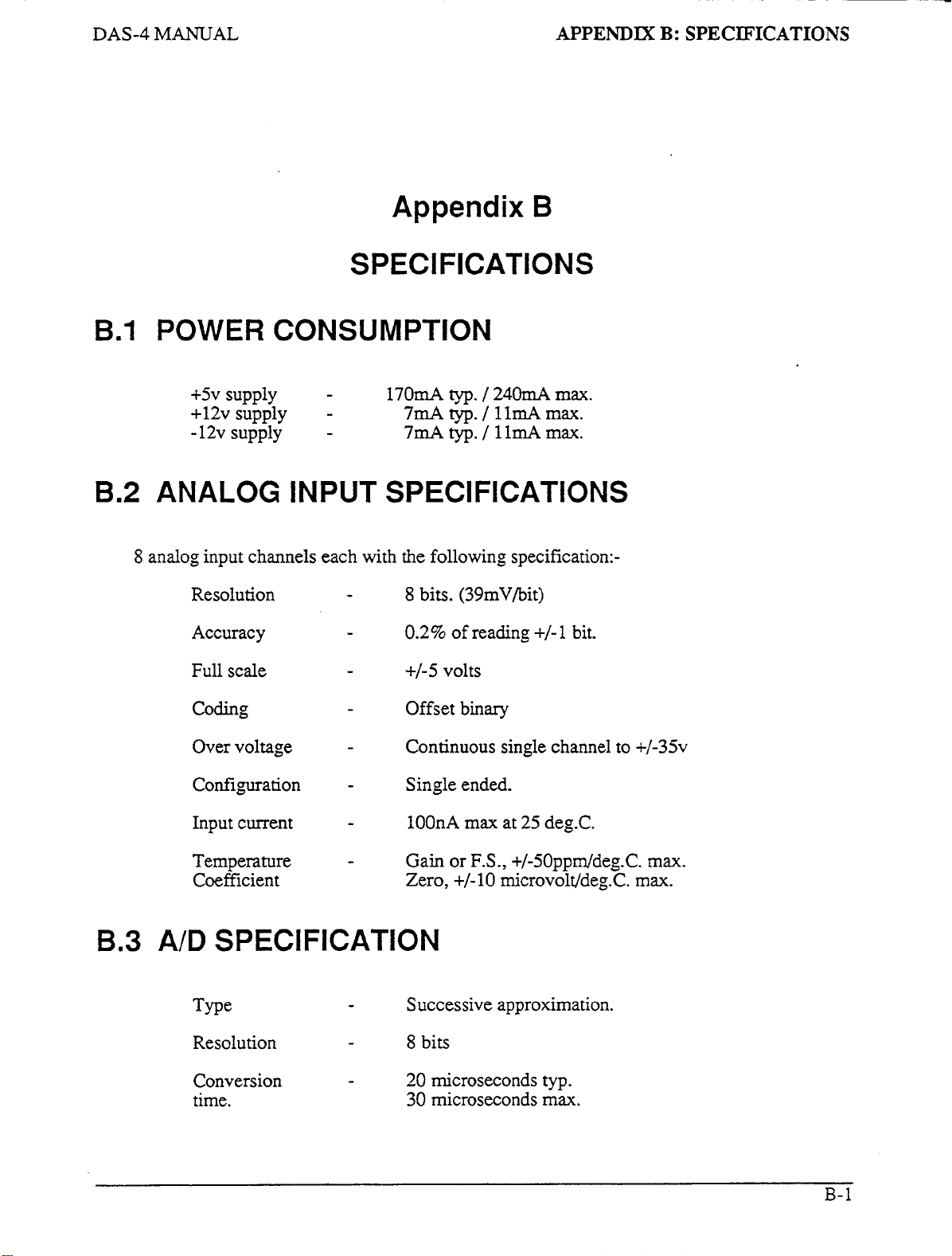
~
-
DAS-4 MANUAL
B.l
B.2
POWER CONSUMPTION
+5v
supply
+12v supply
-12v supply
ANALOG
APPENDIX
Appendix
B
SPECIFICATIONS
-
-
-
170mA
typ.
/
240mA
7mAtyp./llmArnax.
7mA
typ. / 11mA
ma.
max.
INPUT SPECIFICATIONS
B:
SPECIFICATIONS
8
B.3
analog input channels each with the following specification:-
Resolution
Accuracy
Full scale
coding
Over voltage
Configuration
Input current
Temperature
Coefficient Zero, +/-lo microvolt/deg.C. max.
A/D
SPECIFICATION
me
-
-
-
-
-
-
-
-
-
8
bits. (39mV/bit)
0.2%
of
reading
+/-5
volts
Offset binary
Continuous single channel to +/-35v
Single ended.
lOOnA max at 25 deg.C.
Gain or
Successive approximation.
F.S.,
+/-
1
bit.
+/-5Oppddeg.C. max.
Resolution
Conversion
time.
-
-
8
bits
20
microseconds typ.
30
microseconds
ma.
B-
1
Page 57
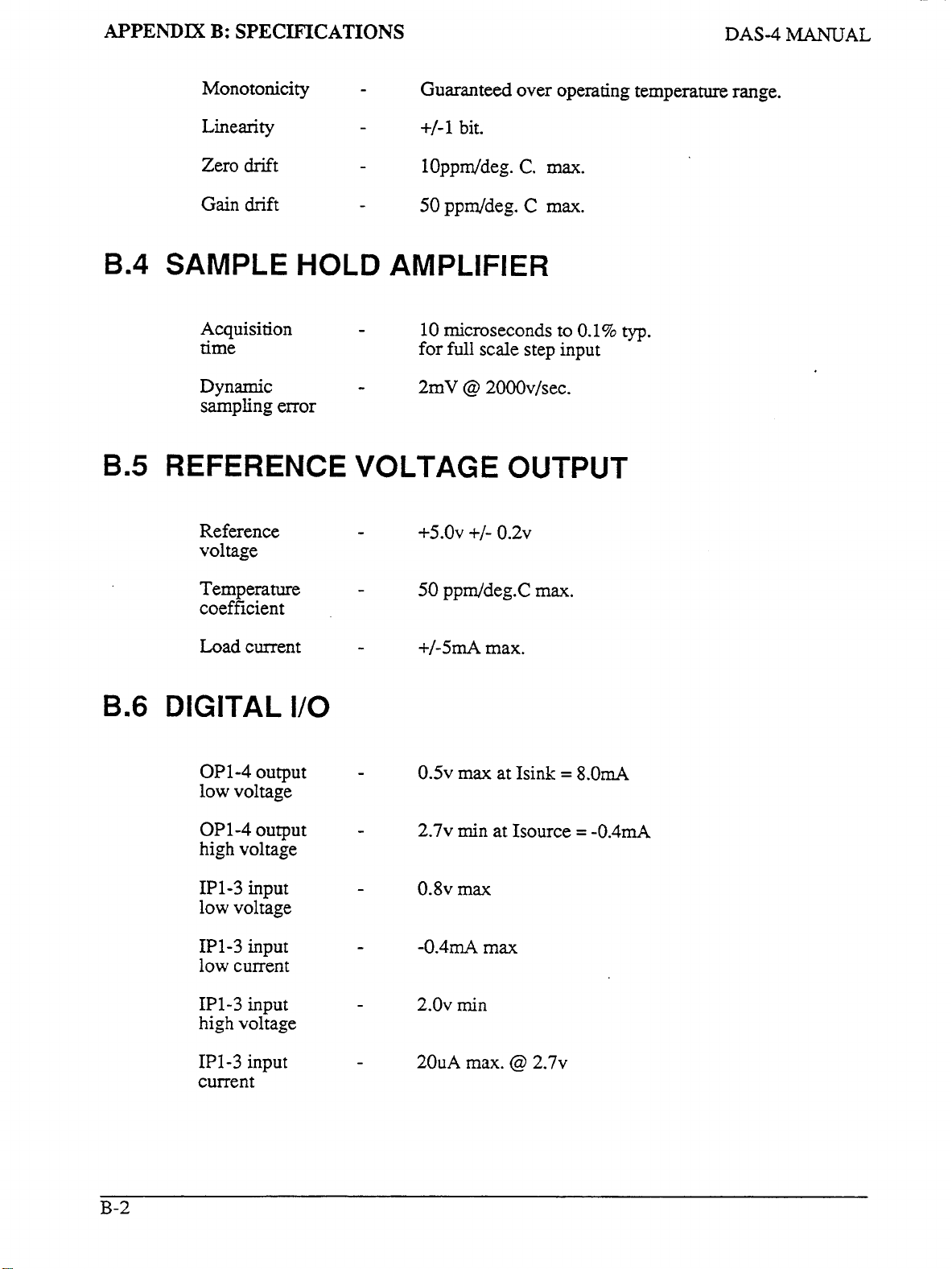
APPENDIX
B:
SPECIFICATIONS
DAS-4
MANUAL
B.4
B.5
Monotonicity
Linearity
Zero
drift
Gain drift
-
-
-
-
Guaranteed over operating temperature range.
+/-1
bit.
10ppddeg.
50
ppddeg. C max.
C.
SAMPLE HOLD AMPLIFIER
Acquisition
time
Dynamic
sampling error
REFERENCE
Reference
voltage
-
-
10 microseconds
for
full
scale step input
2mV @ 2000v/sec.
VOLTAGE OUTPUT
-
+~.OV
+/-
0.2~
max.
to
0.1%
typ.
B.6
Temperature
coefficient
Load current
DIGITAL
OP1-4
low voltage
OP 1-4
high voltage
IP1-3
low voltage
IP1-3
low current
IP1-3
high voltage
output
output
input
input
input
I/O
-
-
-
-
-
-
-
50
ppddeg.C max.
+/-5mA
0.5
2.7~
0.8~ max
-0.4mA
2.0~
max.
max
at Isink
min
at Isource = -0.4mA
max
min
=
8.0mA
B-2
IP1-3
current
input
-
20uA max. @ 2.7~
Page 58

-
DAS-4 MANUAL
B.7
B.8
INTERRUPT
Type
Level
Enable
Interrupts are latched in
this flip-flop corresponds to the
flip-flop is cleared
acknowledge and re-enable the interrupt flop.
POWER OUTPUTS
IBM
P.C.
supplies
APPENDIX
B:
SPECIFICATIONS
INPUT
-
-
-
-
an
by a write to the CONTROL register. Service routines should
bus
-
Positive edge triggered
2
-
7
jumper selectable
Via INTE
internal flip-flop on the
INT
+5v
&
bit
+I-
of
CONTROL register
in
the
STATUS
12v
DAS-4
board. The state
register. The intempt
of
Tolerance
Loading
-
-
+5v
+/-5%
+12~
+/-5%
-12v +/-lo%
Dependent
(see Section
on
other peripherals
4.8)
B.9 GENERAL ENVIRONMENTAL
Operating
temperature
range.
Storage
temperature
range
Humidity
Weight
-
-
-
-
0
to
50
-20 to
0
to
90%
4
oz.
deg.
C.
+70
deg.C.
non-condensing.
(120
gm.)
Page 59

--
DAS-16G
Data is stored
16
bits
but the
range becomes
+32,767
MANUAL
or
2
bytes
2’s
complement convention interprets the most significant bit as a sign bit
D7
0
STORAGE
in
integer variables
of
memory.
-32,768
.
1
to
1
16
+32,767
1
APPENDIX
Appendix
OF
(5%
bits
(a
1
INTEGER
type) in
of
data is equivalent
span
of
65,535).
.
1
1 1
C:
INTEGER
VAR.IABLE
STORAGE
C
VARIABLES
2’s
complement form. Each integer variable uses
to
values
Numbers are represented as follows:-
DO D7
11111111
.
from 0 to
Low
bvte High byte
65,535
so
the-actual
decimal,
.
DO
+lO,OOO
+l
0
-1 11111111 11111111
-
10,000
-32,768 10000000 00000000
Integer variables
16
and
optimize execution speed, all data exchange via the
poses a programming problem when handling unsigned numbers
If you wish to input
work out what
16
bit counter with
execute
most significant bit is
variable value would
between integer and real variables
is therefore:-
0
0
1 0
00000000 00000001
00000000
11011000
A
Sign bit
bit
data of the
its
(1
if negative,
are
the most compact
8254
or
output
2’s
compliment signed equivalent is. As
50,000
PRINT
HEX$(50000).
1
this would
be
50,000 - 65,536 = -15,536.
0
1 1 1
oooioooo
00000000
iiiioooo
0
if
positive)
form
of
storage for the
interval her and
an
unsigned integer greater than
decimal. An easy way of turning this to binary is
This
returns
be
stored as a negative integer and in fact
for
representation of unsigned numbers between 0 and
C350
so
to conserve memory and disk space and
CALL
or binary
12
bit data from the
is
through integer type variables. This
in
the range
32,767
an
example, assume we want to load a
1100 0011 0101
The programming steps
then
A/D
converter
32,768
to
the
to
65,535.
it
is necessary to
enter BASIC and
0000.
Since the
correct integer
for
switching
65,535
From real variable
From integer variable
N
XXXlO
xxx20
(0
<= N <=
IF
N%
to
IF
65,535)
N<=32767
real variable
N%
>=
0
THEN
to
integer variable
THEN
N%
N:-
N=N%
=
N
ELSE
ELSE
N
N%:-
N%
=
=
N%
N
-
+
65536
65536
c-
1
Page 60

Index
A
A/D
-
channel inputs 4-1
A/D
-
conversion by software command 3- 17
A/D
-
conversions
A/D
-
conversions transfer
-
AD
A/D
A/D
A/D
A/D
A/D
Accessories 1-2
Adding analog inputs 4-5
Address map 3-2
Amplifiers
Analog input channels 4Analog inputs B-1
Analog trigger 3-23
Applications 1-2,4-1
Assembly language programming 3-32
Assistance
data format 3-3
-
reading data 3-3
-
sample rate 3-32
-
specification
-
starting conversion 3-2
-
stams
of
&
-
direct
1-1,
operation 3-27
attenuators
technical
5-1
to array 3-19
by
interrupt 3-21
B-1
4-2
1
B
Base address 2-2
Base address switch
Base
I/O
address 2-1
BASIC
BASIC Compiler 3-32
-
some useful commands 3-5
2-2
C
Calibration
CALL routine: Format 3-8,3-9
CALL routine: Initialization 3-13
CALL routine: Loading 3-6
CALL routine: Modes 3-12
Channel inputs
Connecting analog inputs 4-1
Connector assignments
Control register 3-4
Current
5-
loops
1
4-
1
A-1
4-2OmA 4-4
D
DAS4.ASM driver source listing 3-1,3-32
DAS4.BI.N 1-1, 3-1,3-6
Index-
1
Page 61

INDEX
DAS-4 MANUAL
DAS4.0BJ
Differential inputs 4-2
Digital Common 4-6
Digital
Digital
Digital
Disk back up
3-33
VO
1-1,4-4, B-2
VO
-
Output to OP1-4 3-29
VO
-
Reading IP1-3 3-28
2-1
E
Environmental specification
Error codes
EX0 & EXOO.BAS 3-8
Examples of programming
Execution time 3-32
Expansion multiplexer 1-2,4-4,4-5
3-30
B-3
3-31
G
Ground loops
Grounds 4-6
1NSTALL.EXE 2-2
Installation
Instrumentation amplifier 4-3
Integer variables -2’s complement storage
Interrupt - data transfer after operation 3-25
Interrupt
Intempt input 1-1, B-3
Isolated analog inputs
4-6
2-
1
-
determining status of transfer 3-27
1-2
C-
1
L
L.L. Ground 4-6
Loading
Low-level signals
Measuring voltage 4-2
Memory
Memory size
Mode
Mode
Mode 2
Mode
Mode 4
Mode
Mode
Mode 7
Mode
Mode 9
Mode error codes 3-30
Multiple
Multiplexer: Setting scan limits
Multiplexer control 3-5
DAS4.BIN
-
data transfer after interrupt 3-25
3-7
0
-
Initialize
1
-
Set scan limits 3-15
-
Single
3
-
A/D
-
A/D convert on interrupt 3-21
5
-
Analog trigger 3-23
6
-
Transfer data after interrupt 3-25
-
Read status 3-27
8
-
Digital input 3-28
-
Digital output 3-29
DAS-4
3-6
4-3
3-13
A/D
conversion 3-17
convert to array 3-19
boards
3-33
3-15
Index-2
Page 62

DAS-4
MANUAL
0
ON
TlMER command
P
Power consumption
Power outputs
Precautions
Process control current loops
Programming
Programming - example sequences
1-1,4-6, B-3
in
use
3-1
R
Reference Voltage
Repair
5-
1
S
Sample-hold
Sampling rate
Screw terminal board
Semiconductor temperature sensors
Setup
Single ended inputs
software
2-1
Software
Source
Specifications
Speed
Status register
STRIP.EXE
3-32
B-2
3-32
1-1
supplied
listing
1-2
B-
3-3
strip chart program
B-
4-6
1-1, B-2
1-2
4-2
on
disk
1
3-5
1
3-31
INDEX
4-4
3-31
4-5
3-33
T
Technical assistance
Temperature measurement
Temperature sensors - solid state
Thermocouple measurement
5-1
4-5
1-2
V
Voltage reference
4-4
W
WAITc01n~11and3-5
4-5
Index-3
 Loading...