

Page 1
DAS-1800 Series
Function Call Driver
User’s Guide
Page 2

Warranty
Hardware
Keithley Instruments, Inc. warrants that, for a period of one (1) year from
the date of shipment (2 years for Model 199 and 3 years for Models 2000,
2001, 2002, and 2010), the Keithley Hardware product will be free from
defects in materials or workmanship. This warranty will be honored
provided the defect has not been caused by use of the Keithley Hardware
not in accordance with the instructions for the product. This warranty
shall be null and void upon: (1) any modification of Keithley Hardware
that is made by other than Keithley and not approved in writing by
Keithley or (2) operation of the Keithley Hardware outside of the
environmental specifications therefore.
Upon receiving notification of a defect in the Keithley Hardware during
the warranty period, Keithley will, at its option, either repair or replace
such Keithley Hardware. During the first ninety days of the warranty
period, Keithley will, at its option, supply the necessary on site labor to
return the product to the condition prior to the notification of a defect.
Failure to notify Keithley of a defect during the warranty shall relieve
Keithley of its obligations and liabilities under this warranty.
Other Hardware
The portion of the product that is not manufactured by Keithley (Other
Hardware) shall not be covered by this warranty, and Keithley shall have
no duty of obligation to enforce any manufacturers’ warranties on behalf
of the customer. On those other manufacturers’ products that Keithley
purchases for resale, Keithley shall have no duty of obligation to enforce
any manufacturers’ warranties on behalf of the customer.
Page 3
Software
Keithley warrants that for a period of one (I) year from date of shipment
(2 years for Model 199 and 3 years for Models 2000,2001,2002, and
2010), the Keithley produced portion of the software or firmware
(Keithley Software) will conform in all material respects with the
published specifications provided such Keithley Software is used on the
product for which it is intended and otherwise in accordance with the
instructions therefore. Keithley does not warrant that operation of the
Keithley Software will be uninterrupted or error-free and/or that the
Keithley Software will be adequate for the customer’s intended
application and/or use. This warranty shall be null and void upon any
modification of the Keithley Software that is made by other than Keithley
and not approved in writing by Keithley.
If Keithley receives notification of a Keithley Software nonconformity
that is covered by this warranty during the warranty period, Keithley will
review the conditions described in such notice. Such notice must state the
published specification(s) to which the Keithley Software fails to conform
and the manner in which the Keithley Software fails to conform to such
published specification(s) with sufficient specificity to permit Keithley to
correct such nonconformity. If Keithley determines that the Keithley
Software does not conform with the published specifications, Keithley
will, at its option, provide either the programming services necessary to
correct such nonconformity or develop a program change to bypass such
nonconformity in the Keithley Software. Failure to notify Keithley of a
nonconformity during the warranty shall relieve Keithley of its
obligations and liabilities under this warranty.
Other Software
OEM software that is not produced by Keithley (Other Software) shall not
be covered by this warranty, and Keithley shall have no duty or obligation
to enforce any OEM’s warranties on behalf of the customer.
Other Items
Keithley warrants the following items for 90 days from the date of
shipment: probes, cables, rechargeable batteries, diskettes, and
documentation.
Page 4
Items not Covered under Warranty
This warranty does not apply to fuses, non-rechargeable batteries,
damage from battery leakage, or problems arising from normal wear or
failure to follow instructions.
Limitation of Warranty
This warranty does not apply to defects resulting from product
modification made by Purchaser without Keithley’s express written
consent, or by misuse of any product or part.
Disclaimer of Warranties
EXCEPT FOR THE EXPRESS WARRANTIES ABOVE KEITHLEY
DISCLAIMS ALL OTHER WARRANTIES, EXPRESS OR IMPLIED,
INCLUDING WITHOUT LIMITATION, ALL IMPLIED
WARRANTIES OF MERCHANTABILITY AND FITNESS FOR A
PARTICULAR PURPOSE. KEITHLEY DISCLAIMS ALL
WARRANTIES WITH RESPECT TO THE OTHER HARDWARE AND
OTHER SOFTWARE.
Limitation of Liability
KEITHLEY INSTRUMENTS SHALL IN NO EVENT, REGARDLESS
OF CAUSE, ASSUME RESPONSIBILITY FOR OR BE LIABLE FOR:
(I) ECONOMICAL, INCIDENTAL, CONSEQUENTIAL, INDIRECT,
SPECIAL, PUNITIVE OR EXEMPLARY DAMAGES, WHETHER
CLAIMED UNDER CONTRACT, TORT OR ANY OTHER LEGAL
THEORY, (2) LOSS OF OR DAMAGE TO THE CUSTOMER’S DATA
OR PROGRAMMING, OR (3) PENALTIES OR PENALTY CLAUSES
OF ANY DESCRIPTION OR INDEMNIFICATION OF THE
CUSTOMER OR OTHERS FOR COSTS, DAMAGES, OR EXPENSES
RELATED TO THE GOODS OR SERVICES PROVIDED UNDER
THIS WARRANTY.
Page 5
DAS-1800 Series
Function Call Driver
User’s Guide
01997, Keithley Instruments, Inc.
All rights reserved.
Cleveland, Ohio, U.S.A.
Third Printing, August 1997
Document Number: 77160 Rev. C
Page 6

Worldwide Addresses
Keithley Instruments, Inc. ITALY
28775 Aurora Road Keithley Instruments SRL
Clewland, Ohio 44139 Vialc S. Gimignano 38
(440) 248.0400 20146 Milano
Fax: (440) 24X-6168
http://www,keithley.com Fax: 39-2-48302274
39-2-4X30300X
CHINA
Keithley Instruments China
Yuan Chen Xin Building, Room 705
No. 12Yumin Road, Dewei, Madian
Beijing, China 100029
8610.2022856
Fax: 8610.2022892
FRANCE
Keithley Instruments SARL
BP 60
3 all&c des Garays
91122 Palaiseau C&da
31-6-0115155
Fax: 31-6-0117726
GERMANY
Keithley Instruments GmbH
Landsbergcr SwaRc 65
821 IO Garnering
49-89-849307-0
Fax: 49-89-84930759
GREAT BRITAIN
Keithley Instruments, Ltd.
The Minster
58 Portman Road
Reading, Berkshire RG30 IEA
44-01734-575666
Fax: 44-01734-596469
NETHERLANDS
Keithley Instruments BV
Avelingen West 49
4202 MS Gorinchem
31-(0)1X3-635333
Fax: 31.(0)183-630X21
SWITZERLAND
Keithley Instruments SA
Kriesbachstrasse 4
8600 Diibendorf
41-I-8219444
Fax: 41-I-8203081
TAIWAN
Keithley Instruments Taiwan
I, Ming-Yu First Street
Hsinchu. Taiwan, R.O.C.
8X6-35-778462
Fax: 8X6-35-778455
Page 7
Manual Print History
The print history shown below lists the printing dates of all Revisions and Addenda created for
this manual. The Revision Level letter increases alphabetically as the manual undergoes
subsequent updates. Addenda, which are released between Revisions, contain important
change information that the user should incorporate immediately into the manual. Addenda
are numbered sequentially. When a new Revision is created, all Addenda associated with the
previous Revision of the manual are incorporated into the new Revision of the manual. Each
new Revision includes a revised copy of this print history page.
Revision B (Document Number 77160
Revision C (Document Number 77160
Page 8
Safety Precautions
The following safety precautions should be observed before using this
product and any associated instrumentation. Although some instruments
and accessories would normally be used with non-hazardous voltages,
there are situations where hazardous conditions may be present.
This product is intended for use by qualified personnel who recognize
shock hazards and are familiar with the safety precautions required to
avoid possible injury. Read the operating information carefully before
using the product.
The types of product users are:
Responsible body is the individual or group responsible for the use and
maintenance of equipment, and for ensuring that operators are adequately
trained.
Operators use the product for its intended function. They must be trained
in electrical safety procedures and proper use of the instrument. They
must be protected from electric shock and contact with hazardous live
circuits.
Maintenance personnel perform routine procedures on the product to
keep it operating, for example, setting the line voltage or replacing
consumable materials. Maintenance procedures are described in the
manual. The procedures explicitly state if the operator may perform them
Otherwise, they should be performed only by service personnel.
Service personnel are trained to work on live circuits, and perform safe
installations and repairs of products. Only properly trained service
personnel may perform installation and service procedures.
Page 9
Exercise extreme caution when a shock hazard is present. Lethal voltage
may be present on cable connector jacks or test fixtures. The American
National Standards Institute (ANSI) states that a shock hazard exists
when voltage levels greater than 30V RMS, 42.4V peak, or 60VDC are
present. A good safety practice is to expect that hazardous voltage is
present in any unknown circuit before measuring.
Users of this product must be protected from electric shock at all times.
The responsible body must ensure that users are prevented access and/or
insulated from every connection point. In some cases, connections must
be exposed to potential human contact. Product users in these
circumstances must be trained to protect themselves from the risk of
electric shock. If the circuit is capable of operating at or above 1000 volts,
no conductive part of the circuit may be exposed.
As described in the International Electrotechnical Commission (IEC)
Standard IEC 664, digital multimeter measuring circuits (e.g., Keithley
Models 175A, 199, 2000, 2001,2002, and 2010) measuring circuits are
Installation Category II. All other instruments’ signal terminals are
Installation Category I and must not be connected to mains.
Do not connect switching cards directly to unlimited power circuits. They
are intended to be used with impedance limited sources. NEVER connect
switching cards directly to AC mains. When connecting sources to
switching cards, install protective devices to limit fault current and
voltage to the card.
Before operating an instrument, make sure the line cord is connected to a
properly grounded power receptacle. Inspect the connecting cables, test
leads, and jumpers for possible wear, cracks, or breaks before each use.
For maximum safety, do not touch the product, test cables, or any other
instruments while power is applied to the circuit under test. ALWAYS
remove power from the entire test system and discharge any capacitors
before: connecting or disconnecting cables or jumpers, installing or
removing switching cards, or making internal changes, such as installing
or removing jumpers.
Do not touch any object that could provide a current path to the common
side of the circuit under test or power line (earth) ground. Always make
measurements with dry hands while standing on a dry, insulated surface
capable of withstanding the voltage being measured.
Page 10

Do not exceed the maximum signal levels of the instruments and
accessories, as defined in the specifications and operating information,
and as shown on the instrument or test fixture panels, or switching card
When fuses are used in a product, replace with same type and rating for
continued protection against fire hazard.
Chassis connections most only be used as shield connections for
measuring circuits, NOT as safety earth ground connections.
If you are using a test fixture, keep the lid closed while power is applied to
the device under test, Safe operation requires the use of a lid interlock.
If a @screw is present, connect it to safety earth ground using the wire
recommended in the user documentation.
The A symbol on an instrument indicates that the user should refer to
the operating instructions located in the manual.
The A symbol on an instrument shows that it can source or measure
1000 volts or more, including the combined effect of normal and common
mode voltages, Use standard safety precautions to avoid personal contact
with these voltages.
The WARNING heading in a manual explains dangers that might result
in personal injury or death. Always read the associated information very
carefully before performing the indicated procedure.
The CAUTION heading in a manual explains hazards that could damage
the instrument. Such damage may invalidate the warranty.
Instrumentation and accessories shall not be connected to humans.
Before performing any maintenance, disconnect the line cord and all test
cables,
To maintain protection from electric shock and fire, replacement
components in mains circuits, including the power transformer, test leads,
and input jacks, must be purchased from Keithley Instruments. Standard
fuses, with applicable national safety approvals, may be used if the rating
and type are the same. Other components that are not safety related may
be purchased from other suppliers as long as they are equivalent to the
original component, (Note that selected parts should be purchased only
Page 11

through Keithley Instruments to maintain accuracy and functionality of
the product.) If you are unsure about the applicability of a replacement
component, call a Keithley Instruments office for information.
To clean the instrument, use a damp cloth or mild, water based cleaner.
Clean the exterior of the instrument only. Do not apply cleaner directly to
the instrument or allow liquids to enter or spill on the instrument.
Page 12

The information contained in this manual is believed to be accurate and
reliable.
Howcvcr, Kcithley
Instruments, Inc., assumes no responsibility for its use or for any infringements of patents or other rights
of third parties that may result from its USC. No license is granted by implication or otherwise
under any
patent rights of Keithlcy Instruments, Inc.
KEITHLEY INSTRUMENTS, INC., SHALL NOT BE LIABLE FOR ANY SPECIAL, INCIDENTAL,
OR CONSEQUENTIAL DAMAGES RELATED TO THE USE OF THIS PRODUCT. THIS
PRODUCT IS NOT DESIGNED WITH COMPONENTS OF A LEVEL OF RELIABILITY
SUITABLE FOR USE IN LIFE SUPPORT OR CRITICAL APPLICATIONS.
Rcfcr to your Keithley Instruments license agreement and Conditions of Sale document for specific
warranty
and
liability information.
Keithley is a trademark of Keithley Instruments, Inc. All other brand and product names art! trademarks
or
registered
trademarks of their respective companies.
0 Copyright Keithley Instruments, Inc., 1991, 1993, 1994.
All rights reserved. Reproduction or adaptation of any part of this documentation beyond that permitted
by Section
unlawful.
I17 of the 1976 United States Copyright Act without permission of the Copyright owner is
Keithley Instruments, Inc.
28775
Telephone: (440) 248-0400. FAX: (440) 248-6168
Aurora Road Cleveland, OH 44139
Page 13
Table of Contents
Preface
1 Getting Started
Technical Support .....................................
2 Available Operations
System Operations. ..................................
Initializing the Driver ..............................
Initializing a Board ................................
Retrieving Revision Levels. .........................
Handling Errors. ..................................
Analog Input Operations ..............................
Operation Modes. .................................
Memory Allocation and Management.
Gains............................................2- 9
Channels........................................2-10
Specifying Channels When Using EXP- I800 Expansion
Boards (DAS- IEOOSTIHR Series Only).
Acquiring Samples from a Single Channel
Acquiring Samples from a Group of Consecutive
Channels.....................................2-I 3
Acquiring Samples Using a Channel-Gain Queue.
Conversion Modes. .............................
ClockSources....................................2-15
PacerClock....................................2-16
Burst Mode Conversion Clock.
Buffering Modes .................................
Triggers.........................................2-19
TriggerSources ...............................
Internal Trigger .............................
Analog Trigger .............................
Digital Trigger, .. ..........................
Post-Trigger Acquisition ........................
Pre-Trigger Acquisition .........................
About-Trigger Acquisition.
Hardware Gates, ...... ..........................
Analog Output Operations (DA.%I SOOHC Series Only).
................... ,2-l 7
...................... .2-25
1-4
.2-l
.2-2
.2-2
.2-4
.2-4
.2-4
.2-5
................. .2-6
........... .2-l I
.......... ,2- I3
.... .2-14
.,.2-l 5
.2- I8
.2-19
,2- 19
.2-20
.2-22
.2-23
.2-24
.2-25
.... .2-26
Page 14
toe Page iv Monday, April 11, 1994 9:50 AM
Operation Modes.
................
Memory Allocation and Management
Channels .......................
Clock Source. ...................
Buffering Modes. ................
Digital I/O Operations ...............
Operation Modes.
................
Memory Allocation and Management
Digital Input Channel .............
Digital Output Channel. ...........
Clock Source. ...................
Buffering Modes. ................
3
Programming with the Function Call Driver
How the Driver Works.
Programming Overview.
Preliminary Tasks.
...............................
.............................
.................................. .3-11
Operation-Specific Programming Tasks
Analog Input Operations.
Single Mode.
.................................
Interrupt Mode.
........................ .,.3-l 1
...............................
DMAMode...................................3-15
Analog Output Operations (DAS-1800HC Series Only) 3-18
Single Mode
Interrupt Mode.
Digital I/O Operations.
Single Mode.
Interrupt Mode.
.................................. .3-18
............................... .3-18
............................ .3-20
.................................
............................... .3-21
Language-Specific Programming Information
C/Ci+ Languages
............................... ..3-2 3
Allocating and Assigning Dynamically Allocated
Memory Buffers
Single Memory Buffer
Multiple Memory Buffers.
Accessing the Data
............................ .3-23
....................... .3-23
.................... .3-N
.......................... .3-25
Dimensioning and Assigning Local Arrays.
Single Array
Multiple Arrays.
Creating a Channel-Gain
.............................. ..3-2 6
............................
Queue
Programming in Microsoft C/C++.
Programming in Borland C/C++
Programming in Microsoft QuickC for Windows
......
......
......
......
......
......
......
......
......
......
......
......
..... .2-21
..... .2-27
.... ..2-2 8
.... ..2-2 9
.... ..2-3 0
.... ..2-3 1
.... ..2-3 1
..... .2-33
.... ..2-3 4
.... ..2-3 5
.... ..2-3 6
.... ..2-3 8
.3-l
.3-10
.................. 3-l 1
.3-12
.3-12
,3-20
............ ,3-22
.........
,3-25
.3-26
.................. .3-27
................ .3-28
.................. .3-29
...... 3-30
iv
Page 15
raft3.toc
+b
Page v Monday, April 11, 1994 9:50 AM
+b
Programming in Microsoft Visual
Pascal Languages
Allocating and Assigning Dynamically Allocated
Memory Buffers
Reducing the Memory Heap.
Single Memory Buffer
Multiple Memory Buffers.
Accessing the Data
Dimensioning and Assigning Local Arrays. ......... .3-35
Single Array
Multiple Arrays.
Creating a Channel-Gain Queue
Programming in Borland Turbo Pascal (for DOS). .... .3-38
Programming in Borland Turbo Pascal for Windows .. .3-39
Microsoft Visual Basic for Windows
Allocating and Assigning Dynamically Allocated
Memory Buffers
Single Memory Buffer
Multiple Memory Buffers.
Accessing the Data
Dimensioning and Assigning Local Arrays. ......... .3-42
Single Array
Multiple Arrays.
Creating a Channel-Gain Queue
Programming in Microsoft Visual Basic for Windows .3-45
BASIC Languages.
Allocating and Assigning Dynamically Allocated
Memory Buffers
Reducing the Memory Heap.
Single Memory Buffer
Multiple Memory Buffers.
Accessing the Data
Dimensioning and Assigning Local Arrays. ......... .3-48
Single Array
Multiple Arrays
Creating a Channel-Gain Queue
Programming in Microsoft QuickBasic (Version 4.0). .3-51
Programmhtg in Microsoft QuickBasic (Version 4.5). .3-52
Programming in Microsoft Professional Basic
(Version 7.0)
Programming in Microsoft Visual Basic for DOS. .... .3-55
................................
............................
.......................
..........................
..............................
............................
............................
.......................
..........................
...............................
............................ .3-43
...............................
............................
.......................
..........................
...............................
.............................
..............................
C++
.............
..................
.................... .3-34
.................. .3-37
.................
....................
..................
..................
....................
..................
..3-5 3
.3-31
.3-31
,3-32
.3-32
.3-33
.3-35
..3-3 6
.3-36
.3-40
.3-40
.3-40
,3-41
.3-42
.3-42
,344
,3-46
.3-46
.3-46
.3-46
.3-47
.3-48
.3-49
.3-49
.3-50
Page 16

aft3.toc
Page vi Monday, April 11, 1994 9:50 AM
4 Function Reference
DAS1800-DevOpen
DAS1800~GetDevHandle.
K_ADRead.
K-ButListAdd
K-BtdListReset
K-ClearFrame
K-CloseDriver.
K-ClrAboutTrig.
K-ClrADFreeRun
K~ClrContRun.
K-DASDevInit
KDAWrite
................
..............
.............
..............
.............
............
...........
.............
.............
................
K-DIRead .................
K-DMAAlloc
K-DMAFree
K-DMAStart
K-DMAStatus
K-DMAStop
K_DOWrite
K-ForntatChnGAry
K_FreeDevHandle
K-FreeFrame
..............
...............
...............
..............
...............
................
...........
...............
K-GetAboutTrig ............
K-GetADCommonMode. .
K-GetADConfig ............
K-GetADFrame.
K-GetADFreeRun
KGetADMode
K-GetADTrig
............
...........
.............
..............
KGetBuf. .................
K_GetBurstTicks
K-GetChn
KGetChnGAry
K_GetClk.
K-GetClkRate
K-GetCoutRun
............
.................
.............
.................
..............
.............
K-GetDAFrame. ............
K-GetDevHandle. ...........
K-GetDIFratne
K-GetDITrig
K-GetDOCurVal
.............
...............
............
.........
..........
....
. ..4-8
..4-11
..4-14
..4-17
..4-21
..4-23
..4-25
..4-27
,.4-29
..4-31
..4-33
..4-35
..4-38
..4-41
..4-45
..4-47
..4-49
..4-53
..4-56
..4-59
..4-61
..4-63
..4-65
..4-67
..4-69
..4-71
..4-73
..4-76
..4-78
..4-82
..4-85
..4-88
..4-91
..4-93
..4-96
..4-99
.4-102
.4-105
.4-107
.4-110
.4-113
Page 17
raft3.toc Page vii Monday, April 11, 1994 9:50 AM
K-GetDOFrame ................................... .4-116
K-GetErrMsg ..................................... .4-119
K-GetExtClkEdge
................................. .4-121
KGetG.. ...................................... ..4-124
K-GetGatc.
K-GetSheWer.
......................................
...................................
K_GetSSH........................................4-13 2
KGetStartStopChn. ...............................
K-GetStartStopG
.................................. .4-138
K-GetTrig ....................................... .4-142
K-GetTrigHyst .................................... .4-145
K_GetVer.........................................4-14 8
K_lntAloc........................................4-15 1
K-IntFree. ....................................... .4-154
K-IntStart.
.......................................
K-IntStatus ...................................... .4-158
K-IntStop. ....................................... .4- 162
KMakeDMABuf .................................. .4- 165
K-MoveArrayToBuf
K-MoveButToArray ............................... .4-169
K-OpenDriver
.................................... .4-171
K-RestoreChnGAry ................................ .4-174
K-SetAboutTrig. ..................................
K~SetADCommonMode ............................ .4-179
K_Seu\DConfig....................................4-18 1
K-SetADFreeRun .................................
K-SetADMode
.................................. ..4-18 5
K-SetADTrig. .................................... .4-187
KSetBuf.........................................4-19 1
K-SetBufI..
.................................... ..4-19 4
K-SetBurstTicks .................................. .4-196
K_SetChn.........................................4-19 8
K_SetChnGAry....................................4-20 1
K_SetClk.........................................4-2 .
K-SetClkRate .................................... .4-207
K_SetContRun.....................................4-210
KSetDITrig.......................................4-212
K-SetDMABuf ................................... .4-215
K-SetExtClkEdge
.................................
K_SetG...........................................4-22 0
K_SetGate........................................4-22 2
K-SetSSH.. .................................... ..4-2 24
...............................
.4-126
.4-129
.4-135
.4-156
.4- 167
.4-176
.4- 183
.4-218
vii
Page 18
raft3.toc Page viii Monday, April 11, 1994 9:50 AM
II
4
K-SetStartStopChn ............................. .4-226
K-SetStartStopG ............................... .4-230
K-SetTrig ..................................... .4-233
K-SetTrigHyst .................................
A
Error/Status Codes
B
Data Formats
Converting Raw Counts to Voltage .................
Converting Voltage to Raw
Specifying an Analog Output Value
(DAS-1800HC Series only). .................
Specifying au Analog Trigger Level. .............
Specifying a Hysteresis Value. ..................
Index
Counts .................
.4-236
.B-1
.B-3
.B-3
.B-4
.B-5
List of Figures
Figure 2-1. Example of Logical Channel Assignments
Figure 2-2. Trigger Events for Analog Triggers . .
Figure 2-3. Using a Hysteresis Value. .
Figure 2-4. Trigger Events For Digital Triggers
Figure 2-5. Digital Input Bits. . . . . . . .
Figure 2-6.
Figure 3-1. Single-Mode Function.
Figure 3-2. Interrupt-Mode Operation
Digital Output Bits. . . . . . . . . . . . . .
. ..2-12
. . ,2-20
.2-22
.2-23
.2-34
. . .2-35
.3-2
.3-3
Page 19
raft3 tot Page ix Monday, April 11.1994 9:50 AM
1
+I+
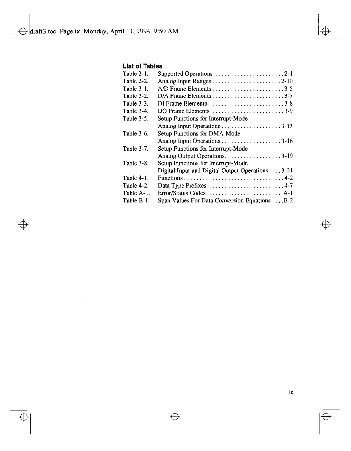
List of Tables
Table 2- 1.
Table 2-2.
Table 3-l.
Table 3-2.
Table 3-3.
Table 3-4.
Table 3-5.
Table 3-6.
Table 3-7.
Table 3-8.
Table 4- 1.
Table 4-2.
Table A-l.
Table B-l.
Supported Operations .2-l
Analog Input Ranges. .2- 10
A/D Frame Elements. .3-5
D/A Frame Elements. .3-7
DI Frame Elements .3-8
DO Frame Elements .3-9
Setup Functions for Interrupt-Mode
Analog Input Operations. .3-13
Setup Functions for DMA-Mode
Analog Input Operations. .3-16
Setup Functions for Interrupt-Mode
Analog Output Operations. .3- 19
Setup Functions for Interrupt-Mode
Digital Input and Digital Output Operations. .3-21
Functions................................4-2
Data Type Prefixes . . .4-7
Error/Status Codes.. . . A-l
Span Values For Data Conversion Equations . . .B-2
ix
Page 20

tot Page x Monday, April 11, 1994 9:50 AM
Page 21
&
reface frm Page xi Monday, April 11, 1994 9:54 AM
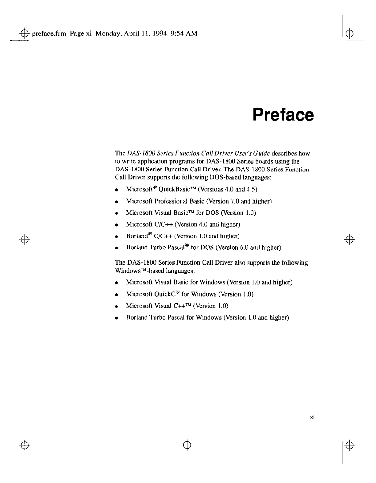
The
DAS-I800 Series Function
to write application programs for DAS- 1800 Series boards using the
DAS-1800 Series Function Call Driver. The DAS-1800 Series Function
Call Driver supports the following DOS-based languages:
. Microsoft@ QuickBasic” (Versions 4.0 and 4.5)
. Microsoft Professional Basic (Version 7.0 and higher)
Cull
Driver
User’s
Preface
Guide
describes how
. Microsoft Visual Basicm for DOS (Version 1.0)
. Microsoft C/C++ (Version 4.0 and higher)
. Borland’ C/C++ (Version 1.0 and higher)
l
Borland Turbo Pascal@ for DOS (Version 6.0 and higher)
The DAS-1800 Series Function Call Driver also supports the following
WindowsTM-based languages:
. Microsoft Visual Basic for Windows (Version 1.0 and higher)
. Microsoft Quick@ for Windows (Version 1.0)
. Microsoft Visual C++TM (Version 1.0)
. Borland Turbo Pascal for Windows (Version 1.0 and higher)
xi
Page 22
4
reface.frm
Page xii Monday, April 11, 1994 9:54 AM
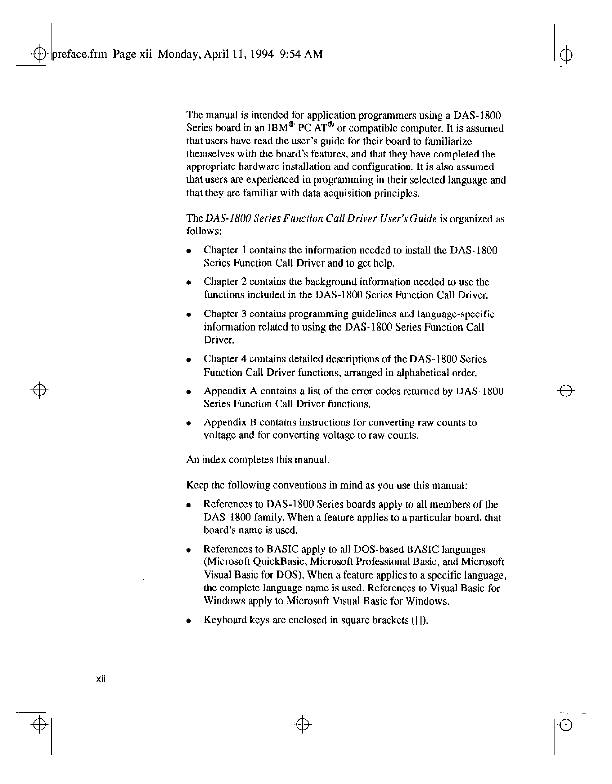
The manual is intended for application programmers using a DAS-1800
Series board in an IBM” PC AT@ or compatible computer. It is assumed
that users have read the user’s guide for their board to familiarize
themselves with the board’s features, and that they have completed the
appropriate hardware installation and configuration. It is also assumed
that users are experienced in programming in their selected language and
that they are familiar with data acquisition principles.
The
DAS-1800 Series Fun&n Call Driver User’s Guide
follows:
Chapter I contains the information needed to install the DAS- 1800
Series Function Call Driver and to get help.
Chapter 2 contains the background information needed to use the
functions included in the DAS-1800 Series Function Call Driver.
Chapter 3 contains programming guidelines and language-specific
information related to using the DAS-1800 Series Function Call
Driver.
is organized as
4
Chapter 4 contains detailed descriptions of the DAS-1800 Series
Function Call Driver functions, arranged in alphabetical order.
Appendix A contains a list of the error codes returned by DAS-1800
Series Function Call Driver functions.
Appendix B contains instructions for converting raw counts to
voltage and for converting voltage to raw counts.
An index completes this manual.
Keep the following conventions in mind as you use this manual:
l
References to DAS-1800 Series boards apply to all members of the
DAS-1800 family. When a feature applies to a particular board, that
board’s name is used.
. References to BASIC apply to all DOS-based BASIC languages
(Microsoft QuickBasic, Microsoft Professional Basic, and Microsoft
Visual Basic for DOS). When a feature applies to a specific language,
the complete language name is used. References to Visual Basic for
Windows apply to Microsoft Visual Basic for Windows.
. Keyboard keys are enclosed in square brackets ([I).
4
xii
4
Page 23
hapOlL.frm Page 1 Monday, April 11, 1994 9:54 AM
t
4
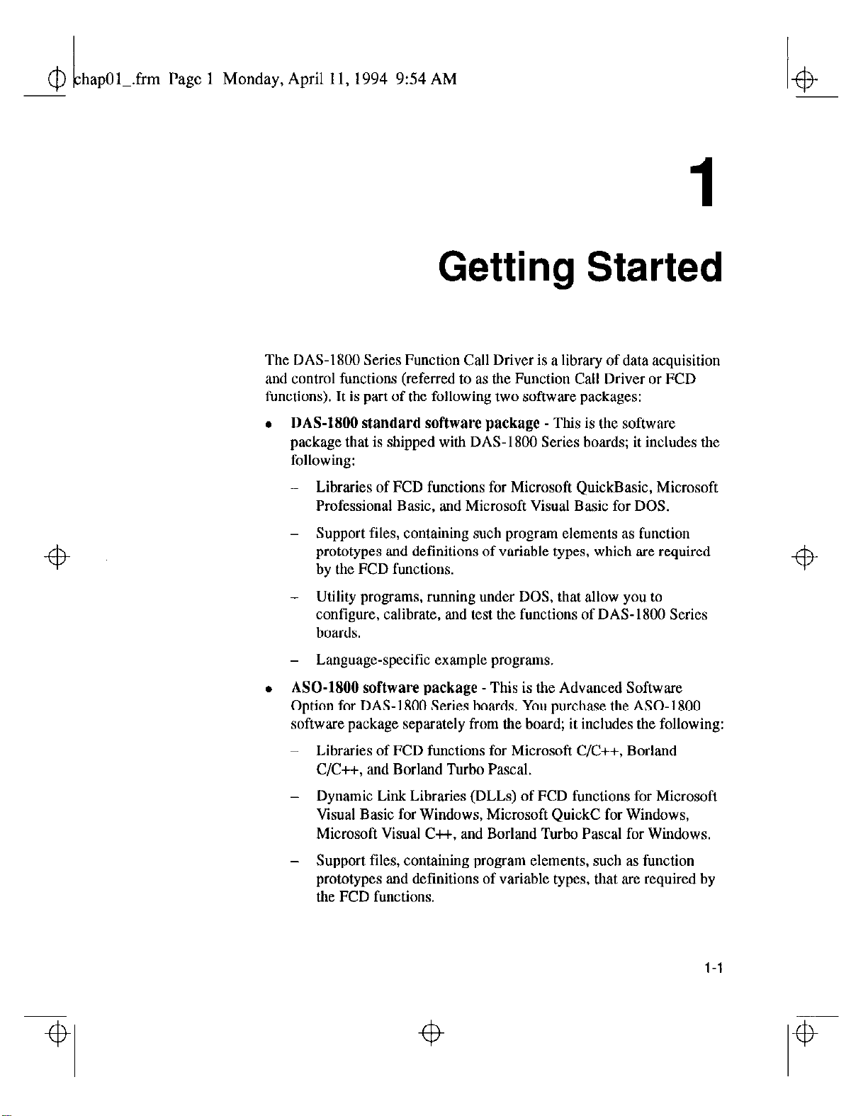
The DAS-1800 Series Function Call Driver is a library of data acquisition
and control functions (referred to as the Function Call Driver or FCD
functions). It is part of the following two software packages:
. DAS-1800 standard software package - This is the software
package that is shipped with DAS- 1800 Series boards; it includes the
followhlg:
- Libraries of FCD functions for Microsoft QuickBasic, Microsoft
Professional Basic, and Microsoft Visual Basic for DOS.
Getting Started
4
- Support files, containing such program elements as function
prototypes and definitions of variable types, which are required
by the FCD functions.
Utility programs, running under DOS, that allow you to
configure, calibrate, and test the functions of DAS-1800 Series
boards.
- Language-specific example programs.
. ASO- software package -This is the Advanced Software
Option for DAS-1800 Series boards. You purchase the ASOsoftware package separately from the board; it includes the following:
Libraries of FCD functions for Microsoft C/C++, Borland
C/C++, and Borland Turbo Pascal.
- Dynamic Link Libraries (DLLs) of FCD functions for Microsoft
Visual Basic for Windows, Microsoft QuickC for Windows,
Microsoft Visual C++, and Borland Turbo Pascal for Windows.
- Support files, containing program elements, such as function
prototypes and definitions of variable types, that are required by
the FCD functions.
4
4
l-l
4
Page 24
Utility programs, running under DOS and Windows, that allow
you to configure, calibrate, and test the functions of DAS- I800
Series boards.
- Language-specific example programs.
Before you use the Function Call Driver, make sure that you have
installed the software, set up the board, and created a configuration file
using the setup and installation procedures described in Chapter 3 of the
user’s guide for your DAS-1800 Series board.
If you need help installing or using the DAS-I 800 Series Function Call
Driver, call your local sales office or the Keithley Instruments, Inc.
Applications Engineering Department at:
(440) 248-1520
Monday - Friday, S:OO A.M. - 6:OO P.M., Eastern Time
1-2
Getting Started
Page 25
Page 3 Monday, April II,1994 954 AM
.frm
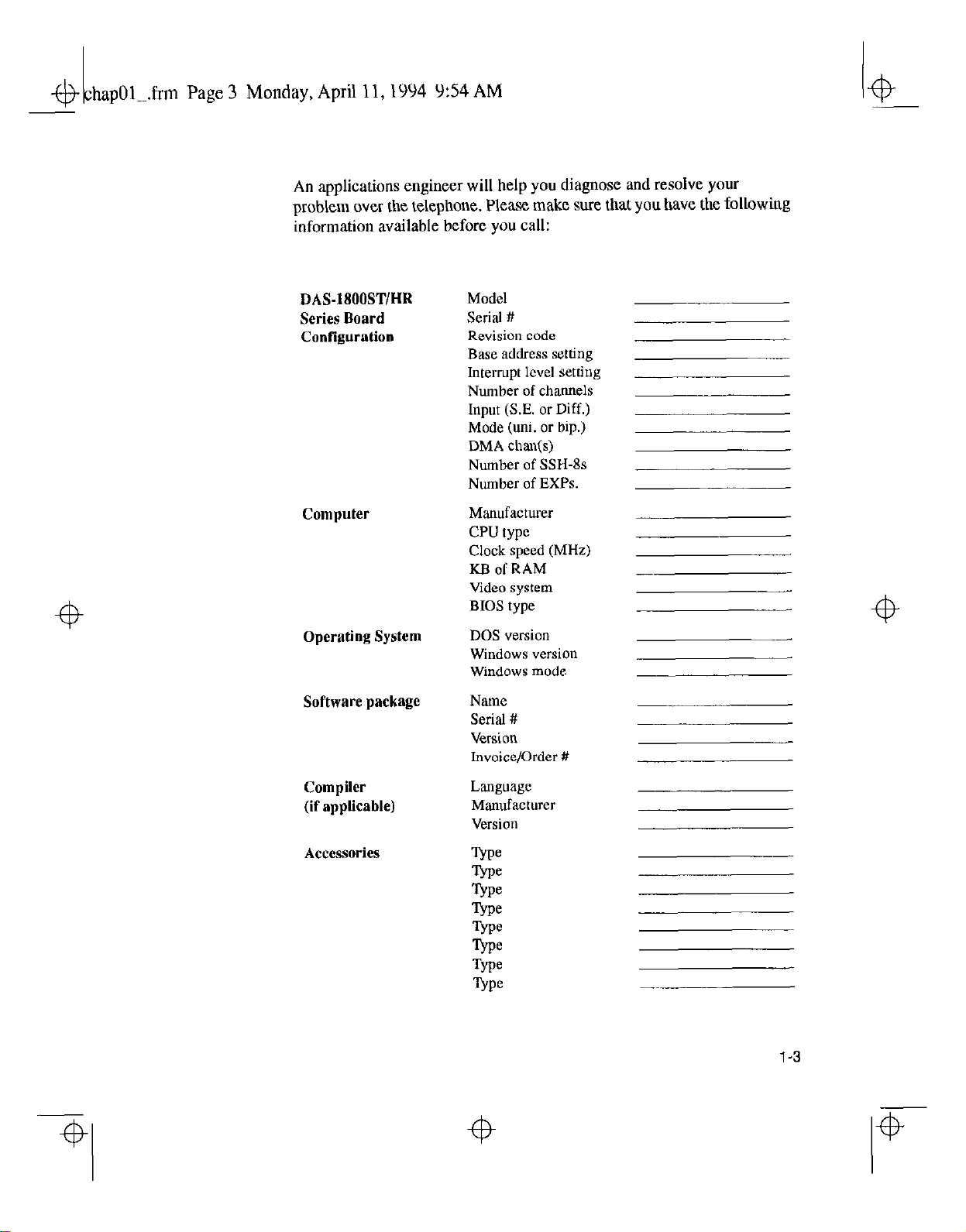
An applications engineer will help you diagnose and resolve yam
problem over the telephone. Please make sure that you have the following
information available before you call:
DAS-1800ST/HR
Series Board
Configuration
Computer
Operating System
Software package
Model
Serial #
Revision code
Base address setting
Interrupt level setting
Number of channels
Input (S.E. or Diff.)
Mode (uni. or hip.)
DMA chax(s)
Number of SSH-8s
Number of EXPs.
Manufacturer
CPU type
Clock speed (MHz)
KB of RAM
Video system
BIOS type
DOS version
Windows version
Windows mode
Name
Serial #
Version
Invoice/Order #
Compiler
(if applicable)
Accessories
Language
Manufacturer
Version
-.
1-3
Page 26

Technical Support
Before returning any equipment for repair, call Keithley Instruments, Inc.,
for technical support at:
An applications engineer will help you diagnose and resolve your
problem over the telephone.
If a telephone resolution is not possible, the applications engineer will
issue you a Return Material Authorization (RMA) number and ask you to
return the equipment. Include the RMA number with any documentation
regarding the equipment.
When returning equipment for repair, include the following information:
. Your name, address, and telephone number
. The invoice or order number and date of equipment purchase.
. A description of the problem or its symptoms.
. The RMA number on the outside of the package
(440) 248-1520
Monday - Friday, 8:00
A.M.
- 6:OO
P.M.,
Eastern Time
Repackage the equipment using the original anti-static wrapping, if
possible, and handle it with ground protection. Ship the equipment to:
ATTN: RMA #
Repair Department
Keithley Instruments, Inc.
31300 Bainbridge Road
Cleveland, OH 44139
Telephone (440) 248-1520
FAX (440) 248-6168
Note: If you are submitting your equipment for repair under warranty,
you must include the invoice number and date of purchase.
To enable. Keithley Instruments, Inc., to respond as quickly as possible,
you must include the RMA number on the outside of the package.
Getting Started
Page 27
hap02 .frm Page 1 Monday, April 11,1994 9:55 AM
& -
Available Operations
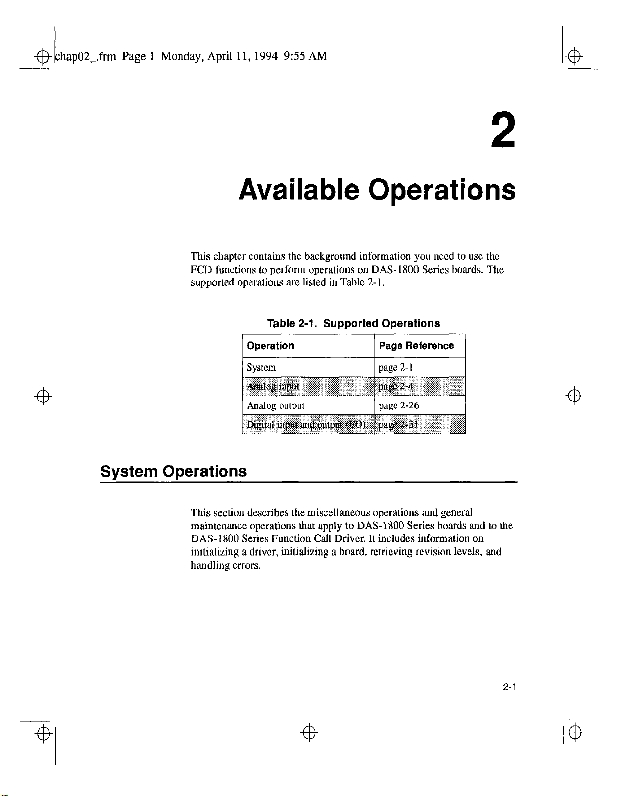
This chapter contains the background information you need to use the
FCD functions to perform operations on DAS- 1800 Series boards. The
supported operations are listed in Table 2-1.
2
Table 2-1. Supported Operations
System Operations
This section describes the miscellaneous operations and general
maintenance operations that apply to DAS-1800 Series boards and to the
DAS-1800 Series Function Call Driver. It includes information on
initializing a driver, initializing a board, retrieving revision levels, and
handling errors.
Operation
System
Page Reference
page z- 1
2-l
Page 28

hap02-.frm
+B
Page 2 Monday, April 11, 1994 955 AM
Initializing the Driver
Before you can use any of the functions included in the DAS-1800 Series
Function Call Driver, you must initialize the driver using one of the
following driver initialization functions:
. Board-specific driver initialization function - If you want to
initialize the DAS-1800 Series Function Call Driver only, use the
board-specific driver initialization function DAN800 DevOpen.
You specify a configuration file; DASlSOO~DevOpe~initializes the
driver according to the configuration file you specify.
. Generic driver initialization function - If you want to initialize
several different Keithley DAS Function Call Drivers from the same
application program, use the generic driver initialization function
K-OpenDriver. You specify the Keithley DAS board you are using,
the configuration file that defines this particular use of the driver, and
the driver handle (a name that uniquely identifies the particular use of
the driver). You can specify a maximum of 30 driver handles for all
the Keithley DAS boards accessed from your application program.
If a particular use of a driver is no longer required and you want to
free some memory or if you have used all 30 driver handles, you can
use the K-CloseDriver function to free a driver handle and close the
associated use of the driver.
If the driver handle you free is the last driver handle specified for a
Function Call Driver, the driver is shut down. (For Windows-based
languages only, the DLLs associated with the Function Call Driver
are shut down and unloaded from memory.)
Initializing a Board
The DAS- 1800 Series Function Call Driver supports up to three boards.
You must use a board initialization function to specify the board(s) you
want to use and the name you want to use to identify each board; this
name is called the board handle. Board handles allow you to
communicate with more than one board. You
specify in the board initialization function in all subsequent function calls
related to the board.
use
the board handle you
2-2
Available Operations
Page 29
hap02_.frm
+b
Page 3 Monday, April 11, 1994 9:55 AM
The DAS-1800 Series Function Call Driver provides the following board
initialization functions:
. Board-specific board initialization function - If you want to
initialize a DAS-1800 Series board only, use the board-specific board
initialization function DAS1800-GetDevHandle.
. Generic board initialization function - If you want to initialize
several different Keithley DAS boards from the same application
program, use the generic board initialization function
K-GetDevHandle. You can specify a maximum of 30 board handles
for all the Keithley DAS boards accessed from your application
program.
If a board is no longer being used and you want to free some memory
or if you have used all 30 board handles, you can use the
K-FreeDevHandle function to free a board handle.
To reinitialize a board during an operation, use the K-DASDevInit
function, which performs the following tasks:
+b
. Abort all operations currently in progress that are associated with the
board identified by the board handle.
l
Verify that the board identified by the board handle is the board
specified in the configuration file.
2-3
Page 30

hap02-.frm Page 4 Monday, April 11,1994 9:55 AM
43
Retrieving Revision Levels
If you are using functions from different Keitbley DAS Function Call
Drivers in the same application program or if you are having problems
with your application program, you may want to verify which versions of
the Function Call Driver, Keithley DAS Driver Specification, and
Keithley DAS Shell are installed on your board. The K-GetVer function
allows you to get both the revision number of the DAS-1800 Series
Function Call Driver and the revision number of the Keithley DAS Driver
Specification to which the driver conforms. The K-GetSheWer function
allows you to get the revision number of the Keithley DAS Shell (the
Keithley DAS Shell is a group of functions that are shared by all DAS
boards).
Handling Errors
Each FCD function returns a code indicating the status of the function. To
ensure that your application program runs successfully, it is recommended
that you check the returned code after the execution of each function. If
the status code equals 0, the function executed successfully and your
program can proceed. If the status code does not equal 0, an error
-@
occurred; ensure that your application program takes the appropriate
action, Refer to Appendix A for a complete list of error codes.
For C-language application programs only, the DAS-1800 Series
Function Call Driver provides the K-GetErrMsg function, which gets
the address of the string corresponding to an error code.
Analog Input Operations
This section describes the following:
. Analog input operation modes available.
. How to allocate and manage memory for analog input operations.
. How to specify the following for an analog input operation: channels
and gains, a conversion mode, a clock source, a buffering mode, a
trigger source, and a hardware gate.
2-4
Available Operations
Page 31

hap02-.frm Page 5 Monday, April 11, 1994 9:55 AM
4
Operation Modes
The operation mode determines which attributes you can specify for an
analog input operation and how data is transferred from the board to the
computer. You can perform analog input operations in one of the
following modes:
. Single mode - In single mode, the board acquires a single sample
from an analog input channel. The driver initiates conversions; you
cannot perform any other operation until the single-mode operation is
complete.
Use the K-ADRead function to start an analog input operation in
single mode. You specify the board you want to use, the analog input
channel, the gain at which you want to read the signal, and the
variable in which to store the converted data.
. Interrupt mode -In interrupt mode, the board acquires a single
sample or multiple samples from one or more analog input channels.
A hardware clock initiates conversions. Once the analog input
operation begins, control returns to your application program. The
4
hardware temporarily stores the acquired data in the onboard FIFO
(first-in, first-out data buffer) and then transfers the data to a
user-defined buffer in the computer using an interrupt service routine.
4
4
Use the K-IntStart function to start an analog input operation in
interrupt mode. You specify the board, analog input channel(s),
gain(s), clock source, buffering mode, buffer address( trigger
source, and gate use.
You can specify either single-cycle or continuous buffering mode for
interrupt-mode operations. Refer to page Z- 18 for more information
on buffering modes. Use the K-IntStop function to stop a
continuous-mode interrupt operation. Use the K-IntStatus function
to determine the current status of an interrupt operation.
. DMA mode - In DMA mode, the hoard acquires a single sample or
multiple samples from one or more analog input channels. A
hardware clock initiates conversions. Once the analog input operation
begins, control returns to your application program. The hardware
temporarily stores the acquired data in the onboard FfFO (first-in,
4
4
4
Page 32

hapOZ.fim Page 6 Monday, April 11,1994 9:55 AM
4
first-out data buffer) and then transfers the data to a user-defined
DMA buffer in the computer.
Note: You can perform an analog input operation in single-DMA
mode or dual-DMA mode, depending on whether you specified one
or two DMA channels in your configuration file. Refer to your
DAS-1800 Series board user’s guide for more information.
Use the K-DMAStart function to start an analog input operation in
DMA mode. You specify the board, analog input channel(s), gain(s),
clock
source,
gate use.
You can specify either single-cycle or continuous buffering mode for
DMA-mode operations. Refer to page 2- 18 for more information on
buffering modes. Use the K-DMAStop function to stop a
continuous-mode DMA operation. Use the K-DMAStatus function
to determine the current status of a DMA operation.
buffering mode, buffer address( trigger source, and
4
The converted data are stored as raw counts. For information on
converting raw counts to voltage, refer to Appendix B.
Memory Allocation and Management
Interrupt-mode and DMA-mode analog input operations require memory
buffers in which fo store the acquired data. You can reserve a single
memory buffer, or you can reserve multiple buffers (up to a maximum of
150) to increase the number of samples you can acquire. The maximum
number of samples each memory buffer can store (32K or 64K) depends
on the language you are using. See “Language-Specific Programming
Information” on page 3-22 for more information.
4
2-6
Available Operations
Page 33

hap02-.frm Page 7 Monday, April 11, 1994 9:55 AM
4
You can reserve the required memory buffer(s) in one of the following
ways:
l
Within your application program’s memory area -The simplest
way to reserve memory buffers is to dimension arrays within your
application program. The advantage of this method is that the arrays
are directly accessible to your application program. The limitations of
this method are as follows:
Certain programming languages limit the size of local arrays.
-
Local arrays may not be suitable for DMA-mode operations.
- Local arrays occupy permanent memory areas; these memory
areas cannot be freed to make them available to other programs or
processes.
Since the DAS-1800 Series Function Call Driver stores data in 16-bit
integers, you must dimension all local arrays as integers.
4
4
l
Outside of your application program’s memory area -This is the
recommended way to reserve memory buffers. The advantages of this
method are as follows:
-
The number of buffers and the size of each buffer are limited by
the amount of free physical memory available in your computer
at run-time.
-
The dynamically allocated memory buffers can be freed to make
them available to other programs or processes.
The limitation of this method is that, for BASIC and Visual Basic
languages, the data in a dynamically allocated memory buffer is not
directly accessible by your program. (The DAS-1800 Series Function
Call Driver provides a function, K-MoveButToArray, to make this
data accessible; refer to page 4-169 for more information.)
4
4
4
2-7
4
Page 34

4
hap02Lfrm
Page 8 Monday, April 11, 1994 955 AM
Use the K-IntAlloc function to allocate memory dynamically for
interrupt-mode operations and the K-DMAAlloc function to allocate
memory dynamically for DMA-mode operations. You specify the
operation requiring the buffer, the number of samples to store in the
buffer, the variable to store the starting address of the buffer, and the
name you want to use to identify the buffer (this name is called the
memory handle). When the buffer is no longer required, you can free
the buffer for another use by specifying this memory handle in the
K-IntFree function (for interrupt-mode operations) or the
K-DMAFree function (for DMA-mode operations).
Notes: For DOS-based languages, the area used for dynamically
allocated memory buffers is referred to as the far heap; for
Windows-based languages, this area is referred to as the global heap.
These heaps are areas of memory left unoccupied as your application
program and other programs run.
4
4
For DOS-based languages, the K-IntAlloc and K-DMAAlloc
functions use the DOS Int 21H function 48H to dynamically allocate
far heap memory. For Windows-based languages, the K
K-DMAAlloc functions call the GlobalAlloc API fun&on to
allocate the desired buffer size from the global heap.
For Windows-based languages, dynamically allocated memory is
guaranteed to be fixed and locked in memory.
To eliminate page wrap conditions and to guarantee that dynamically
allocated memory is suitable for use by the computer’s 8237 DMA
controller, K-DMAAlloc may allocate an area twice as large as
actually needed. Once the data in this buffer is processed and/or saved
elsewhere, use K-DMAFree to free the memory for other
IntAlloc
uses.
and
4
4
Z-8
Available Operations
4
Page 35

hap02Lfrm Page 9 Monday, April 11, 1994 9:55 AM
4
After you allocate your buffer(s), you must assign the starting address of
the buffer(s) and the number of samples to store in the buffer(s). Each
supported programming language requires a particular procedure for
allocating memory buffers and assigning starting addresses. Refer to page
3-23 for information when programming in C. Refer to page 3-31 for
information when programming in Pascal. Refer to page 3-40 for
information when programming in Visual Basic for Windows. Refer to
page 3-46 for information when programming in BASIC.
If you are using multiple buffers, use the K-BufListAdd function to add
each buffer to the list of multiple buffers associated with each operation
and to assign the starting address of each buffer. Use the KBufListReset
function to clear the list of multiple buffers.
4
4
Gains
Note:
the Keithley Memory Manager before you begin programming to ensure
that you can allocate large enough buffers. Refer to your DAS-1800
Series board user’s guide for more information about the Keithley
Memory Manager.
Each channel on a DAS-1800 Series board can measure analog input
signals in one of four, software-selectable unipolar or bipolar analog input
ranges. The input range type (unipolar or bipolar) is initially set according
to your configuration file; use K-SetADMode to reset the input range
type. Refer to your DAS-1800 Series board user’s guide for more
information.
Table 2-2 lists the analog input ranges supported by DAS-1800 Series
boards and the gain and gain code associated with each range. (The gain
code is used by the FCD functions to represent the gain.)
If you are using multiple buffers, it is recommended that you use
4
4
4
2-9
4
Page 36

& hap02-.frm
Page 10 Monday, April 11,1994 9:55 AM
Table 2-2. Analog input Ranges
Analog Input Range
DAS-1801HC
DAS-1801ST
DAS-1802HR
4
4
Channels
2-l 0
DAS-18OOHC Series boards are configured with either 64 single-ended or
32 differential analog input channels, depending on the input
configuration specified in your configuration file. DAS-1800ST/HR
Series boards are configured with either 16
onboard differential analog input channels. On DAS-1800ST/HR Series
boards, you can increase the number of channels to 2.56 single-ended or
128 differential channels using the EXP-1800
in the next section.
onboard
single-ended or 8
expansion board, described
Available Operations
4
4
4
Page 37

hap02-.frm Page 11 Monday, April 11, 1994 9:55 AM
t
4
The input channel configuration is initially set according to the
configuration file; use K-SetADConfig to reset the input channel
configuration. Use K-SetADCommonMode to set the common-mode
ground reference for DAS- 18OOST/HR Series boards in single-ended
input channel configuration.
You can perform an analog input operation on a single channel or on a
group of multiple channels. The following subsections describe how to
specify the channel(s) you are using.
Specifying Channels When Using EXP-1800 Expansion Boards
(DAS-18OOST/HR Series Only)
To increase the number of analog input channels, you can attach up to 16
EXP-1800 expansion boards to the DAS-1800 Series board. Each
EXP-1800 board has 16 analog input channels. If you are using
N EXP-1800 boards, you must attach them to DAS-1800 channels 0 to
N-J.
Refer to the
connecting EXP-1800 boards to DAS-1800STiHR Series boards.
DAS-1800STIHR Series
User’s
Guide
for information on
4
The analog input channel connections on a DAS-1800 Series board or
EXP-1800 board are labelled with white-on-green numbers from 0 to 15.
These numbers are the physical channel
DAS-1800 Series board and one or more EXF-1800 boards, then that
system contains duplicate physical channel numbers. To uniquely identify
a physical channel, the Function Call Driver uses a scheme of logical
chunnel numbers.
specified as a logical channel number.
The
charm&
argument for any FCD function must be
number.?.
If a system includes a
4
4
2-l 1
4
Page 38

4 hap02-.frm Page 12 Monday, April 11, 1994 9:55 AM
The logical channel number corresponding to a particular physical
channel number is given by one of the following equations:
If the physical channel is on a DAS-1800 Series board:
LogicalChan# = PhysicalChatS + (15 x NumEXPs)
If
the physical channel is on an EXP-1800 board:
where
For example, consider the system illustrated in Figure 2- 1, in which three
EXP1800 boards are connected to a DAS-IROIST.
DAS-18OiST
LugicalChan# = PhysicalChan# +
NumEXPs
is an integer from 0 to 15 that identifies the number of
(16 x
EXP#)
EXI- 1800 boards connected to the DAS- 1800 Series board, and
EXP#
is an integer from 0 to 15 that indicates on which EXP-1800
board the physical channel is located (0 indicates the lirst EXP-1800
board).
0 1 2 15
EXP #O Logical Channels 0 to 15
0 1 2 15
EXP #I Logical Channels 16 to 31
0 1 2 15
EXPW Logical Channels 32 to 47
3
1.5 Logical Chancel 60
Logical
Channel 43
2-12
Figure 2-1. Example of Logical Channel Assignments
Available Operations
Page 39

hap02Lfrm Page 13 Monday, April 11, 1994 9:55 AM
The logical channel that identifies channel 3 on the DAS-1801 board is
given by:
LogicalChan# = 3 +
The logical channel that identifies channel 15 on the third EXP-1800
board is given by:
LogicalChard =
(15 x 3) = 3 +45 = 48
15 + (16 x 2) = 15 + 32 = 47
Acquiring Samples from a Single Channel
You can acquire a single sample or multiple samples from a single analog
input channel.
For single-mode analog input operations, you can acquire a single sample
from a single analog input channel. Use the
specify the channel and the gain code.
For interrupt-mode and DMA-mode analog input operations, you can
acquire a single sample or multiple samples from a single analog input
channel. Use the
K-Se@ function to specify the gain code.
K-SetChn
function to specify the channel and the
K-ADRead
Acquiring Samples from a Group of Consecutive Channels
function to
4
For interrupt-mode and DMA-mode analog input operations, you can
acquire samples from a group of consecutive channels. Use the
K-SetStartStopChn
group. The channels are sampled in order from first to last: the
are then sampled again until the required number of samples are read.
For example, assume that the start channel is 14, the stop channel is 17,
and you want to acquire five samples. Your program reads data first from
channel 14, then from channels 15, 16, and 17, and finally from channel
14 again.
You can specify a start channel that is higher than the stop channel. For
example, assume that you are using a differential input configuration, the
start channel is 3 1, the stop channel is 2, and you want to acquire five
samples. Your program reads data first from channel 3 1, then from
channels 0, 1, and 2, and finally from channel 31 again.
function to specify the first and last channels in the
channels
Z-13
Page 40

hap02-.frm Page 14 Monday, April 11, 1994 9:55 AM
+B
Use the K-SetG function to specify the gain code for all channels in the
group. (All channels must use the same gain code.) Use the
K-SetStartStopG function to specify the gain code, the start channel,
and the stop channel in a single function call.
Refer to Table 2-2 on page 2-10 for a list of the analog input ranges
supported by DAS-1800 Series boards and the gain code associated with
each range.
Acquiring Samples Using a Channel-Gain Queue
For interrupt-mode and DMA-mode analog input operations, you can
acquire samples from channels in a hardware channel-gain queue. In the
channel-gain queue, you specify the channels you want to sample, the
order in which you want to sample them, and a gain code for each
channel.
You can set up the channels in a channel-gain queue either in consecutive
order or in nonconsecutive order. You can also specify the same channel
more than once (up to a total of 64 entries in the queue for a
DAS-1800HC Series board, and up to 256 entries for a DAS-lSOOST/HR
Series board).
2-14
The channels are sampled in order from the first channel in the queue to
the last channel in the queue; the channels in the queue are then sampled
again until the board reads the specified number of samples.
Refer to Table 2-2 on page 2-10 for a list of the analog input ranges
supported by DAS-1800 Series boards and the gain code associated with
each range.
The way that you specify the channels and gains in a channel-gain queue
depends on the language you are using. Refer to page 3-27 for
information when programming in C or C++. Refer to page 3-37 for
information when programming in Pascal. Refer to page 3-44 for
information when programming in Visual Basic for Windows. Refer to
page 3-50 for information when programming in BASIC.
After you create the channel-gain queue in your program, use the
K-SetChnGAry function to transfer the contents of the channel-gain
queue to the driver/board.
Available Operations
Page 41

hap02-.frm Page 15 Monday, April 11, 1994 9:55 AM
Conversion Modes
The conversion mode determines how the board regulates the timing of
conversions when you are acquiring multiple samples from a single
channel or from a group of multiple channels (known as a scan). For
interrupt-mode and DMA-mode analog input operations, you can specify
one of the following conversion modes:
. Paced mode - Use paced mode if you want to accurately control the
period between conversions of individual channels in a scan. Paced
mode is the default conversion mode.
. Burst mode -Use burst mode if you want to accurately control both
the period between conversions of individual channels in a scan and
the period between conversions of the entire scan. Use the
K-SetADFreeRun function to specify burst mode.
Use burst mode with SSH if you want to simultaneously sample all
channels in a scan using the SSH-8 accessory board. Use the
K-SetSSH function to specify burst mode with SSH.
Refer to your DAS-1800 Series board user’s guide for more information
about conversion modes.
Clock Sources
DAS-1800 Series boards provide two clock sources: a pacer clock and a
burst mode conversion clock. Each clock has a dedicated use. When
performing interrupt-mode and DMA-mode analog input operations ln
paced mode, you use only the pacer clock: when performing
interrupt-mode and DMA-mode analog input operations in burst mode
and burst mode with SSH, you use both the pacer clock and the burst
mode conversion clock. These clock sources are described in the
following subsections,
Note:
If you use an SSH-8 accessory board, you must use burst mode
with SSH. One extra tick of the burst mode conversion clock is
required to allow the SSH-8 board to sample and hold the values.
Refer to the SSH-8 board documentation for more infortnation.
2-15
Page 42

hap02_.frm Page 16 Monday, April II,1994 9:55 AM
I
+P
In paced mode, the pacer clock determines the period between the
conversion of one channel and the conversion of the next channel. In
burst mode and burst mode with SSH, the pacer clock determines the
period between the conversions of one scan and the conversions of the
next scan. Use the K-SetClk function to specify an internal or an external
pacer clock. The internal pacer clock is the default pacer clock.
The internal and external pacer clocks are described as follows:
. Internal pacer clock - The internal pacer clock uses two cascaded
counters of the onboard counter/timer circuitry. The counters are
normally in an idle state. When you start the analog input operation
(using K-IntStart or K-DMAStart), a conversion is initiated. Note
that a slight time delay occurs between the time the operation is
started and the time conversions begin.
After the first conversion is initiated, the counters are loaded with a
count value and begin counting down. When the counters count down
to 0, another conversion is initiated and the process repeats.
Because the counters use a 5 MHz time base, each count represents
0.2 ps. Use the K-SetClkRate function to specify the number of
counts (clock ticks) between conversions. For example, if you specify
a count of 30, the period between conversions is 6 ps
(166.67 ksamples/s); if you specify a count of 87654, the period
between conversions is 17.53 ms (57 samples/s).
You can specify a count between 15 and 4,294,967,295. The period
between conversions ranges from 3 @LS to 14.3 minutes.
When using an internal pacer clock, use the following formula to
determine the number of counts to specify:
COUntS = 5 MHz time base
conversion rate
Z-16
Available Operations
Page 43

hap02-.frm
+b
Page 17 Monday, April 11,1994 9:55 AM
For example, if you want a conversion rate of 10 ksamples/s, specify
a count of 500, as shown in the following equation:
5,000,~~0 = 5oo
10,000
. External pacer clock - You connect an external pacer clock to the
DIO/XPCLK pin (pin B39) on the main I/O connector of the
DAS- 1800HC Series board or to the XPCLK pin (pin 44) on the main
I/O connector of DAS-1800ST/HR Series boards. When you start an
analog input operation (using K-IntStart or K-DMAStart),
conversions are armed. At the next active edge of the external pacer
clock (and at every subsequent active edge of the external pacer
clock), a conversion is initiated. Use the K-SetExtClkEdge function
to specify the active edge (rising or falling) of the external pacer
clock. A falling edge is tbe default active edge for the external pacer
clock.
+P
Note:
board depends on a number of factors, including your computer, the
operating system/environment, the gains of the channels, and other
software issues. If you are using an external pacer clock, make sure that
the clock initiates conversions at a rate that the analog-to-digital converter
can handle.
Refer to your DAS-1800 Series board user’s guide for more information
about the pacer clock.
The rate at which the computer can reliably read data from the
Burst Mode Conversion Clock
In burst mode and burst mode with SSH, the burst mode conversion clock
determines the period between the conversion of one channel in a scan
and the conversion of the next channel in the scan.
Because the burst mode conversion clock uses a 1 MHz time base, each
clock tick represents 1 ks. Use the K-SetBurstTicks function to specify
the number of clock ticks between conversions. For example, if you
specify 30 clock ticks, the period between conversions is 30 ps
(33.33 ksamples/s).
2-I 7
Page 44

hap02-.frm Page 18 Monday, April 11, 1994 9:55 AM
43
You can specify between 3 and 255 clock ticks. The period between
conversions ranges from 3 ps to 0.255 ms.
When using the burst mode conversion clock, use the following formula
to determine the number of clock ticks to specify:
For example, if you want a burst mode conversion rate of 10 ksamples/s,
specify 100 clock ticks, as shown in the following equation:
Refer to your DAS-1800 Series board user’s guide for more information
about the burst
Buffering Modes
The buffering mode determines how the driver stores the converted data
in the buffer. For interrupt-mode and DMA-mode analog input
operations, you can specify one of the following buffering modes:
. Single-cycle mode - In single-cycle mode, after the board converts
clock
ticks =
1,000,000 = 1oo
mode
conversion clock.
the specified number of samples
operation stops automatically. Single-cycle mode is the default
buffering mode.
I MHz time base
burst mode conversion rate
IO, 000
and stores them
in the
buffer, the
2-18
. Continuous mode - In continuous
converts samples and stores them in the buffer until it receives a stop
function; any values already stored in the buffer are overwritten. Use
the K-SetContRun function to specify continuous buffering mode.
mode,
the board continuously
Available Operations
Page 45

hap02-.frm Page 19 Monday, April 11, 1994 955 AM
t
+b
Triggers
A trigger is an event that starts or stops an interrupt-mode or DMA-mode
analog input operation. An operation can use either one or two triggers.
Every operation must have a start trigger that marks the beginning of the
operation. You can use an optional second trigger, the
define when the operation stops. If you specify an about trigger, the
operation stops when a specified number of samples has been acquired
after the occurrence of the about-trigger event.
A post-trigger acquisition refers to an operation that only uses a start
trigger. The about trigger provides the capability to define operations that
acquire data before a trigger event (pre-trigger acquisition) and operations
that acquire data about (before and after) a trigger event (aboul-trigger
acquisition).
The following subsections describe the supported trigger sources and
post-, pre-, and about-trigger acquisitions.
about trigger,
to
Trigger Sources
The Function Call Driver supports three sources of triggers: internal,
analog, and digital. For interrupt-mode and DMA-mode analog input
operations, use K-SetlXg to specify the trigger source. The lrigger
events for each trigger source are described below. Note that the trigger
event is not significant until the operation the trigger governs has been
enabled (using K-DMAStart or K-IntStart).
Internal Trigger
An internal trigger is a software trigger. It does not impose any external
conditions that must be satisfied before the operation executes. An
operation governed by an internal start trigger begins executing as soon as
the operation is enabled. Consequently, the call to K-DMAStart or
K-IntStart
internal trigger is the default trigger source.
is considered the trigger event for an internal trigger. The
2-i 9
Page 46

hapOZ.frm Page 20 Monday, April 11.1994 955 AM
43
Analog Trigger
You can use the signal on any analog input channel as the trigger signal
for an analog trigger. The trigger events for analog triggers are illustrated
in Figure 2-2 and described as follows:
. If the trigger polarity is positive, a trigger event occurs the first time
the trigger signal changes from a voltage that is less than the trigger
level to a voltage that is greater than the trigger level.
l
If the trigger polarity is negative, a trigger event occurs the first time
the trigger signal changes from a voltage that is greater than the
trigger level to a voltage that is less than the trigger level.
2-20
Figure 2-2. Trigger Events for Analog Triggers
Note: Analog triggering is a feature of the Function Call Driver and is
not implemented at the hardware level. Consequently, there is a delay
between the time the trigger event occurs and the time the driver
recognizes that the trigger event occurred.
Available Operations
Page 47

&- hapOZ_.frm Page 21 Monday, April 11, 1994 9:55 AM
You can specify a hysteresis value to prevent noise from triggering an
operation. Use the K-Set’IkigHyst function to speci-ly the hysteresis
value. For a positive-edge trigger, the analog signal most be below the
specified voltage level by at least the amount of the hysteresis value and
then rise above the voltage level before the trigger occurs: for a
negative-edge trigger, the analog signal must be above the specified
voltage level by at least the amount of the hysteresis value and then fall
below the voltage level before the trigger occurs.
The hysteresis value is an absolute number, which you specify as a raw
count value between 0 and 4095 for DAS-1800HC/ST Series boards and
between 0 and 65,535 for DAS-1800HR Series boards. When you add the
hysteresis value to the voltage level (for a negative-edge trigger) or
subtract the hysteresis value from the voltage level (for a positive-edge
trigger), the resulting value must also be between 0 and 4095 for
DAS-1800STEIC Series boards or between 0 and 65,535 for
DAS-1800HR Series boards. For example, assume that you are using a
negative-edge trigger on a channel of a DAS-1800HC/ST Series board
configured for an analog input range of f5 V. If the voltage level is +4.8 V
(4014 counts), you can specify a hysteresis value of 0.1 V (41 counts)
because 4014 + 41 is less than 4095, but you cannot specify a hysteresis
4+
value of 0.3 V (123 counts) because 4014 + 123 is greater than 4095.
Refer to Appendix B for information on how to convert a voltage value to
a raw count value.
In Figure 2-3, the specified voltage level is +4 V and the hysteresis value
is 0.1 V. The analog signal must be below +3.9 V and then rise above
+4 V before a positive-edge trigger occurs; the analog signal must be
above +4.1 V and then fall below +4 V before a negative-edge trigger
occurs.
2-21
Page 48

hapOZ.frm Page 22 Monday, April 11, 1994 9:55 AM
Level +‘q ”
\
trigger occ”rs
2-22
Figure 2-3. Using a Hysteresis Value
Digital Trigger
The digital trigger signal is available on the DIl,TGIN pin (pin 840) on
the main I/O connector of DAS1800HC Series boards and on the TGIN
pin (pin 46) on the main I/O connector of DAS-1800STiHR Series
boards. Use K SetDI’Ikig to specify whether you want the trigger event
to occur on a rising or falling
a trigger event occurs at each rising edge of the trigger signal. If the
trigger polarity is negative, then a trigger event occurs at each falling edge
of the trigger signal. These trigger events are illustrated in Figure 2-4.
edge.
If the trigger polarity is positive, then
Available Operations
Page 49

hap02-.frm Page 23 Monday, April 11, 1994 955 AM
a
-. . . .
Trigger signal 2 u I
Triggersigcal -
Figure 2-4. Trigger Events For Digital Triggers
Trigger
went
\H-l ll
Trigger e/vent
+b
Post-Trigger Acquisition
Use post-trigger acquisition in applications where you want to collect data
after a specific event. Acquisition starts on an internal, analog, or digital
trigger event and continues until a specified number of samples has been
acquired or until the operation is stopped by a call to K-DMAStop or
K-IntStop.
To specify post-trigger acquisition, use the following function calls:
1. If you want acquisition to continue until you stop it using
K-DMAStop or K-In&Stop, use K-SetContRun to set the buffering
mode to continuous.
2. If you want acquisition to stop after a specified number of samples
has been acquired, use K ClrContRun to set the buffering mode to
single-cycle (in this buffekg mode, the operation stops as soon as
the board has acquired the number of samples specified by
K-SetBuf, K-SetDMABuf, K-SetBufI, or K-BufListAdd).
Z-23
Page 50

hap02-.frm Page 24 Monday, April 11, 1994 955 AM
4
3. Specify the trigger that will start the operation. Use K-Set’Ikig to
specify the trigger source (internal for an internal trigger, external for
an analog or digital trigger).
4. If you are using an analog or digital trigger, use K-SetAD’Ikig (for an
analog trigger) or K-SetDITrig (for a digital trigger) to define the
trigger conditions.
5. Use K-ClrAbout’Ikig to disable the about trigger.
Pre-Trigger Acquisition
Use pre-trigger acquisition in applications where you want to collect data
before a specific digital trigger event (this is the
Acquisition starts on an internal, analog, or digital trigger event and
continues until the about-trigger event. Pm-trigger acquisition is available
with DMA-mode operations only.
about trigger
4
event).
4
To specify pre-trigger acquisition, use the following function calls:
1. Specify the trigger that will start the operation. Use K-Set’Ikig to
specify the trigger source (internal for an internal trigger, external for
an analog or digital trigger).
2. If using an analog or digital start trigger, use KTSetADTrig (for an
analog trigger) or K-SetDITrig (for a digital tngger) to define the
trigger conditions.
3. Use K-SetAboutWig to enable the about trigger and to set the
number of post-trigger samples to 1.
4. If the start trigger is not digital, specify the trigger conditions for the
about trigger. Use K Set’IYig to specify an external trigger, then use
K-SetDl’Ikig to speky the trigger conditions. (If the start trigger is
digital, then its trigger conditions are also
used
for the about trigger).
4
2-24
4
Available Operations
4
Page 51

4
hapOl.frm
About-Trigger Acquisition
Page 25 Monday, April 11.1994 9:55 AM
Use about-trigger acquisition in applications where you want to collect
data both before and after a specific digital trigger event (this is the about
trigger event). Acquisition starts on an internal, analog, or digital trigger
event and continues until a specified number of samples has been
acquired after the about-trigger event. About-trigger acquisition is
available with DMA-mode operations only.
To specify about-trigger acquisition, use the following function calls:
1. Specify the trigger that will start the operation. Use K-SetWig to
specify the trigger source (internal for an internal trigger, external for
an analog or digital trigger).
2. If using an analog or digital start trigger, use K SetADTrig (for an
analog trigger) or K-SetDITrig (for a digital trigger) to define the
trigger conditions.
4
3. Use K-SetAboutTrig to enable the about trigger and to specify the
4. Specify the trigger conditions for the about trigger. Use K SetDITrig
Hardware Gates
A hardware gate is an externally applied digital signal that determines
whether conversions occur. You connect the gate signal to the DIl/TGIN
pin (pin B40) on the main I/O connector of DAS-1800HC Series boards
or on the TGIN pin (pin 46) on the main I/O connector of
DAS- 1 800ST/HR Series boards. If you have started an interrupt-mode or
DMA-mode analog input operation (using K-IntStart or K-DMAStart)
and the hardware gate is enabled, the state of the gate signal determines
whether conversions occur.
If the board is configured with a positive gate, conversions occur only if
the signal to DHRGIN (DAS-1800HC Series boards) or TGIN
(DAS-lSCOST/IIR Series boards) is high; if the signal to DIl/IGIN or
TGIN is low, conversions are inhibited. If the board is configured with a
negative gate, conversions occur only if the signal to Dll/TGIN is low; if
desired number of post-trigger samples,
4
to specify the trigger conditions. (If the start trigger is digital, then its
trigger conditions are also used for the about trigger).
4
2-25
+P-
Page 52

hap02_.frm Page 26 Monday, April 11,1994 955 AM
6
the signal to DIl/TGIN is high, conversions are inhibited. Use the
K-SetGate function to enable and disable the hardware gate and to
specify the gate polarity (positive or negative). The default state of the
hardware gate is disabled.
You can use the hardware gate with an external analog trigger. The
software waits until the analog trigger conditions are met, and then the
hardware checks the state of the gate signal.
If you are not using an analog trigger, the gate signal itself can act as a
trigger. If the gate signal is in the inactive state when you start the analog
input operation, the hardware waits until the gate signal is in the active
state before conversions begin.
-e
Note: You
you use a digital trigger at one point in your application program and later
want to use a hardware gate, you must fxst disable the digital trigger. You
disable the digital trigger by specifying an internal trigger in K-SetTrig
or by setting up an analog trigger (using the K-SetADTrig function).
cannot use the hardware gate with an external digital trigger. If
Analog Output Operations (DAS-1800HC Series Only)
This section describes the following:
. Analog output operation modes available.
. How to allocate and manage memory for analog output operations.
. How to specify the following for an analog output operation:
channels, a clock rate, and a buffering mode.
Note:
analog output operation.
You cannot use an external trigger or external pacer clock with an
2-26
Available Operations
Page 53

hap02_.tim
@-
Operation Modes
Page 27 Monday, April 11,1994 955 AM
The operation mode determines which attributes you can specify for an
analog output operation. You can perform analog output operations in one
of the following modes:
. Single mode - In single mode, the driver writes a single value to one
or both analog output channels; you cannot perform any other
operation until the single-mode operation is complete.
Use the K-DAWrite function to start an analog output operation in
single mode. You specify the board you want to use, the analog output
channel(s), and the value you want to write.
. Interrupt mode In interrupt mode, the driver writes a single value
or multiple values to one or both analog output channels. A hardware
clock paces the updating of the analog output channel(s). Once the
analog output operation begins, control returns to your application
program. You store the values you want to write in a user-defined
buffer in the computer.
Use the K-IntStart function to start an analog output operation in
interrupt mode. You specify the board, analog output channel(s),
clock rate, buffering mode, and buffer address.
You can specify either single-cycle or continuous buffering mode for
interrupt-mode operations. Refer to page Z-30 for more information
on buffering modes. Use the K-I&top function to stop a
continuous-mode interrupt operation. Use the K-IntStatus function
to determine the current status of an interrupt operation.
For an analog output operation, the values are written as raw counts. For
information on converting voltage to raw counts, refer to Appendix B.
Memory Allocation and Management
Interrupt-mode analog output operations use a single memory buffer to
store the data to be written to the analog output channel(s). The maximum
number of samples each memory buffer can store (32K or 64K) depends
on the language you are using. See “Language-Specific Programming
Information” on page 3-22 for more information.
2-27
Page 54

hap02Lfrm
Page 28 Monday, April 11, 1994 9:55 AM
Since analog output operations typically require small arrays of data, you
can reserve a memory buffer by dimensioning aa array within your
application program’s memory area. Since the DAS-1800 Series Function
Call Driver writes data as 16-bit integers, you must dimension all local
arrays as integers.
Channels
Note:
dynamically, if desired. You specify the operation requiring the buffer, the
number of values you want to store in the buffer, the starting address of
the buffer, and the name you want to use to identify the buffer (this name
is called the memory handle). When the buffer is no longer required, you
can free the buffer for another use by specifying this memory handle in
the K-IntFree function.
After you dimension your array, you must assign the starting address of
the array and the number of samples
programming language requires a particular procedure for dimensioning
an array and assigning the starting address. Refer to page 3-23 for
information when programming in C or C++. Refer to page 3-3 1 for
information when programming in Pascal. Refer to page 3-40 for
information when programming in Visual Basic for Windows. Refer to
page 3-46 for information when programming in BASIC.
DAS-1800HC Series boards contain two digital-to-analog converters,
each of which is associated with an analog output channel. You can
perform aa analog output operation on a single channel or on both
channels.
You can
also
use the K-IntAlloc function to allocate memory
stored
in the anay. Each supported
2-28
For single-mode analog output operations, you can write a single value to
one or both analog output channels. Use the K-DAWrite function to
specify the channel(s).
For interrupt-mode analog output operations, you can write a single value
or multiple values to one or both analog output chan;leIs. Use the
K-SetChn function to specify a single channel. Use the
K-SetStartStopChn
start channel and analog output channel 1 as the stop channel. When
function to specify analog output channel 0 as the
using
Available Operations
Page 55

hap02-.frm Page 29 Monday, April 11, 1994 9:55 AM
e
both channels, the first value in the buffer is written to channel 0, the
second value is written to channel 1, the third value is written to channel 0
again, and so on. After all the values in the buffer are written once, the
values are written again until the required number of values are written.
For example, assume that your buffer contains three values (123,456, and
789) and you want to write five values. Your program writes 123 to
channel 0,456 to channel 1,789 to channel 0, 123 to channel 1, and 456
to channel 0.
Clock Source
When performing interrupt-mode analog output operations, you can use
the internal pacer clock to determine the period between the updating of a
single analog output channel or between each simultaneous updating of
both analog output channels.
Note:
another operation.
The internal pacer clock uses two cascaded counters of the onboard
counter/timer circuitry. The counters are normally in an idle state. When
you start the analog output operation (using K-IntStart), the analog
output channel(s) are updated. Note that a slight time delay occurs
between the time the operation is started and the time the channel(s) are
updated.
The counters are loaded with a count value and begin counting down.
When the counters count down to 0, the channel(s) are updated again and
the process repeats.
Because the counters use a 5 MHz time base, each count represents
0.2 ps. Use the K-SetClkRate function to specify the number of counts
(clock ticks) between updates. For example, if you specify a count of
5000, the period between updates is 1 ms (1 ksamples/s); if you specify a
count of 87654, the period between updates is 17.53 ms (57 samples/s).
You can specify a count between 15 and 4,294,967,29.5. The period
between updates ranges from 3 ps to 14.3 minutes.
You can use the internal pacer clock only if it is not being used by
2-29
Page 56

hap02_.frm Page 30 Monday, April 11, 1994 9:55 AM
4
4
Note:
FIFO is not used to buffer values for analog output operations, a low
count value may cause an overrun error, The maximum observed update
rates for the internal pacer clock are 1 ksamples/s when running under
Windows and 5 ksamples/s when mnning under DOS. These rates would
indicate a minimum count of 5,000 when running under Windows and
Use the following formula to determine the number of counts to specify:
For example, if you want to update the analog output channels at a rate of
500 samples/s, specify a count of 10,000, as shown in the following
equation:
The driver accepts a count value as low as 15. However, since the
1,000 when running under DOS.
counts =
5,000~000 = 10 ooo
5 MHz time base
update rate
500 ’
4
Buffering Modes
The buffering mode determines how the driver writes the values in the
buffer to the analog output channels. For interrupt-mode analog output
operations, you can specify one of the following buffering modes:
.
. Continuous mode -In continuous mode, the driver continuously
2-30
Single-cycle mode
values stored in the buffer, the operation stops automatically.
Single-cycle mode is the default buffering mode.
writes values from the buffer until the application program issues a
stop function; when all the values in the buffer have been written, the
driver writes the values again. Use the K-SetContRun function to
specify continuous buffering mode.
- In single-cycle mode, after the driver writes the
Available Operations
Page 57

hap02Lfrm
+I+
Page 31 Monday, April 11,1994 955 AM
Digital l/O Operations
This section describes the following:
. Digital I/O operation modes available.
. How to allocate and manage memory for digital I/O operations,
l
Digital I/O channels
. How to specify the following for a digital I/O operation: a clock rate
and a buffering mode.
Note:
digital I/O operation.
Operation Modes
The operation mode determines which attributes you can specify for a
digital I/O operation. You can perform digital I/O operations in one of the
following modes:
l
Single
reads the value of digital input channel 0 once; in a single-mode
digital output operation, the driver writes a value to digital output
channel 0 once. You cannot perform any other operation until the
single-mode operation is complete.
Use the K-DIRead function to start a digital input operation in single
mode; use the K-DOWrite function to start a digital output operation
in single mode. You specify the board you want to use, the digital I/O
channel, and the variable in which the value is stored.
You cannot use an external trigger or external pacer clock with a
mode
- In a single-mode digital input operation, the driver
2-31
Page 58

4
hap02Lfrm
Page 32 Monday, April 11, 1994 955 AM
Notes: Since digital input channel 0 is only four bits wide, you must
mask the value stored by K-DIRead with 15 (OF%) to obtain the
actual digital input value.
The value written by K-DOWrite must be a 32-bit value. For
DAS-1800HC Series boards, the eight least significant bits contain
the actual digital output value, and all other bits are irrelevant. For
DAS-lXOOST/HR Series boards, the four least significant bits contain
the actual digital output value, and all other bits are irrelevant.
. Interrupt mode - In an interrupt-mode digital input operation, the
driver reads the value of digital input channel 0 multiple times; in an
interrupt-mode digital output operation, the driver writes a single
value or multiple values to digital output channel 0 multiple times. A
hardware clock paces the digital I/O operation. Once the digital I/O
operation begins, control returns to your application program. The
driver stores digital input values in a user-defined buffer in the
computer; you store digital output values in a user-defined buffer in
the computer.
4
2-32
Note: The digital input buffer and the digital output buffer each
4
contain 16-bit integers. Each digital input value is stored in the four
least significant bits of each integer in the digital input buffer. For
DAS-1800HC Series boards, each digital output value is stored in tic
eight least significant bits of each integer in the digital output buffer.
For DAS-1800ST/HR Series boards, each digital output value is
stored in the four least significant bits of each integer in the digital
output buffer.
Use the K-IntStart function to start a digital I/O operation in
interrupt mode. You specify the board, digital I/O channel, clock rate,
buffering mode, and buffer address.
You can specify either single-cycle or continuous buffering mode for
interrupt-mode operations. Refer to page 2-38 for more information
on buffering modes. Use the K-IntStop function to stop a
continuous-mode interrupt operation. Use the K-In&Status function
to determine the current status of an interrupt operation.
Available Operations
4
4 4
Page 59

hap02Lfrm Page 33 Monday, April 11, 1994 9:55 AM
4
Memory Allocation and Management
Interrupt-mode digital I/O operations use a single memory buffer to store
the data to be read or written. The maximum number of samples each
memory buffer can store (32K or 64K) depends on the language you are
using. See “Language-Specific Programming Information” on page 3-22
for more information.
Since digital I/O operations typically require small arrays of data, you can
reserve a memory buffer by dimensioning an array within your
application program’s memory area. Since the DAS-1800 Series Function
Call Driver reads and writes data as 16-bit integers, you must dimension
all local arrays as integers.
4
4
Note:
dynamically, if desired. You specify the operation requiring the buffer, the
number of values to store in the buffer, the variable in which to store the
starting address of the buffer, and the name you want to use to identify the
buffer (this name is called the memory handle). When the buffer is no
longer required, you can free the buffer for another use by specifying this
memory handle in the KIntFree function.
After you dimension or allocate your array, you must assign the starting
address of the array and the number of samples to store in the array. Each
supported programming language requires a particular procedure for
dimensioning an array and assigning the starting address. Refer to page
3-23 for information when programming in C or C++. Refer to page 3-31
for information when programming in Pascal. Refer to page 3-40 for
information when programming in Visual Basic for Windows. Refer to
page 3-46 for information when programming in BASIC.
You can also
use
the K-IntAlloc function to allocate memory
4
2-33
Page 60

hap02-.frm Page 34 Monday, April 11, 1994 9:55 AM
4
Digital Input Channel
DAS-1800 Series boards contain one 4.bit digital input channel
(channel 0).
input line 0 (DIO/KPCLK on DAS-18OOHC Series boards, DIO on
DAS-lSOOST/HR Series
line I (DIl/TGIN on DAS-1800HC Series boards, DIl on
DAS1800STiHR Series boards); bit 2 contains the value of digital input
line 2 (D12): bit 3 contains the value of digital input line 3 (D13).
As
shown in Figure 2-5, bit 0 contains the value of digital
boards);
4
bit 1 contains the value of digital input
4
bit 3
DASl800HC
Figure 2-5. Digital Input Bits
A value of 1 in the bit position indicates that the input is high; a value of 0
in the
bit
position indicates that the input is low. For example, if the value
is 5 (OlOl), the input at DIO/XPCLK and DI2 is high and the input at
DIllrGIN and D13 is low.
Dl3 D12
bit3
bit 2
bit 2
bit 1
D,l/ DIO,
TGIN XPCLK
bit 1
bit 0
bit 0
4
2-34
Available Operations
4
Page 61

.frm Page 35 Monday, April 11, 1994 9:55 AM
Notes: If no signal is connected to a digital input line, the input appears
high (value is 1).
@AS-1800HC Series boards only) If you are using an external pacer
clock, you cannot use digital input line 0 for general-purpose digital input
operations. If you are using an external digital trigger, you cannot use
digital input line 1 for general-purpose digital input operations. When
reading digital input channel 0, ignore the value of these bits.
Digital Output Channel
DAS-1800HC Series boards contain one 8-bit digital output channel
(channel 0). DAS-1800ST/HR Series boards contain one 4.bit digital
output chauuel (channel 0). As shown in Figure 2-6, bit 0 contains the
value to be written to digital output line 0 (DOO), bit 1 contains the value
to be written to digital output line 1 (DOl), and so on.
DAS1800STfHR Series
bit? bit6 bit5 bit4 bit3 bit2 bit 1 bit 0
DC7 DO6 DDS DD4 DD3 DC2 DD, DO0
DAS-ISOOHC Series
I I
Figure 2-6. Digital Output Bits
A value of I in the bit position indicates that the output is high: a value of
0 in the bit position indicates that the output is low. For example, if the
value written is I2 (OOOOllOO), the output at DOO, DOl, D04, D05,
D06, and DO7 is forced low and the output at DO2 and DO3 is forced
high.
2-35
Page 62

A?
hap02-.frm
Page 36 Monday, April 11, 1994 9:55 AM
43
Clock Source
Note:
K-GetDOCurVal function to read the last digital output value written to
digital output channel 0 using K-DOWrite.
When performing interrupt-mode digital I/O operations, you can use the
internal pacer clock to determine the period between reading the digital
input channel or writing to the digital output channel.
Note:
another operation.
The internal pacer clock uses two cascaded counters of the onboard
counter/timer circuitry. The counters are normally in an idle state. When
you start the digital I/O operation (using K-b&tart), a value is read or
written. Note that a slight time delay occurs between the time the
operation is started and the time the reading or writing begins.
The DAS-1800 Series Function Call Driver provides the
You can use the internal pacer clock only if it is not being used by
2-36
The counters are loaded with a count value and begin counting down.
When the counters count down to 0, another value is read or written and
the process repeats,
Because the counters use a 5 MHz time base, each count represents
0.2 ps. Use the K-SetClkRate function to specify the number of counts
(clock ticks) between reads or writes. For example, if you specify a count
of 5000, the period between reads or writes is 1 ms (1 ksamples/s); if you
specify a count of 87654, the period between reads or writes is 17.53 ms
(57 samples/s).
You can specify a cotmt between I5 and 4,294,967,295. The period
between reads or writes ranges from 3 us to 14.3 minutes.
Available Operations
Page 63

.frm Page 37 Monday, April 11, 1994 9:55 AM
Note:
FIFO is not used to buffer values for digital I/O operations, a low count
value may cause overrun errors. The maximum observed update rates for
the internal pacer clock are 1 ksamples/s when mnning under Windows
and 5 ksamplesls when running under DOS. These rates would indicate a
minimum count of 5,000 when running under Windows and 1,000 when
running under DOS.
Use the following formula to determine the number of counts to specify:
For example, if you want to write data to digital output channel 0 at a rate
of 500 samples/s, specify a count of 10,000, as shown in the following
equation:
The driver accepts a count value as low as 15. However, since the
COUntS = 5 MHz time base
read/write rate
5,000,000
500
= 10,000
2-37
Page 64

hapOZ.frm
43
Page 3X Monday, April 1 I, 1994 9:55 AM
Buffering Modes
The buffering mode determines how the driver reads or writes the values
in the buffer. For interrupt-mode digital I/O operations, you can specify
one of the following buffering modes:
.
Single-cycle mode
after the driver fills the buffer, the operation stops automatically. In a
single-cycle-mode digital output operation, after the driver writes the
values stored in the buffer, the operation stops automatically.
Single-cycle mode is the default buffering mode.
- In a single-cycle-mode digital input operation,
. Continuous mode
driver continuously reads digital input channel 0 and stores the values
in the buffer until the application program issues a stop function; any
values already stored in the buffer are overwritten. In a continuous
mode digital output operation, the driver continuously writes values
from the buffer to digital output channel 0 until the application
program issues a stop function; when all the values in the buffer have
been written, the driver writes the values again. You use the
K-SetContRun
-In a continuous-mode digital input operation, the
function to specify continuous buffering mode.
2-38
Available Operations
Page 65

Programming with the
Function Call Driver
This chapter contains an overview of the stmcture of the DAS-1800
Series Function Call Driver, as well as programming guidelines and
language-specific information to assist you when writing application
programs with the DAS-I 800 Series Function Call Driver.
How the Driver Works
When writing application programs, you can use functions from one or
more Keithley DAS Function Call Drivers. You initialize each driver
according to a particular configuration file. If you are using more than one
driver or more than one configuration file with a single driver, the driver
handle uniquely identifies each driver or each use of the driver.
3
You can program one or more boards in your application program. You
initialize each board using a board handle to uniquely identify each board.
Each board handle is associated with a particular driver.
The Function Call Driver(s) allow you to perform I/O operations in
various operation modes, For single mode, the I/O operation is performed
with a single call to a function; the attributes of the I/O operation are
specified as arguments to the function. Figure 3-I illustrates the syntax of
the single-mode, analog input operation function K-ADRead.
3-l
Page 66

hap03-.frm Page 2 Monday, April 11,1994 9:57 AM
+I+
+B
Sinale-Mode Function
K-ADRead (board,
channel, e Analog input channel
Wh
buffer) - Buffer for data
Figure 3-1. Single-Mode Function
For other operation modes, such as interrupt mode
driver uses frames to perform the I/O operation. A frame is a data
structure whose elements define the attributes of the I/O operation. Each
frame is associated with a particular board, and therefore, to a particular
driver.
Frames help you create structured application programs. You set up the
attributes of the I/O operation in advance, using a separate function call
for each attribute, and then start the operation at an appropriate point in
your program. Frames are useful for operations that have many defining
attributes, since providing a separate argument for each attribute could
make a function’s argument list unmanageably long. In addition, some
attributes, such as the clock source and trigger source, are only available
for I/O operations that use frames.
utes of ODeration
M Board number
- Gain applied to channel
and
DMA mode, the
3-2
You indicate that you want to perform an I/O operation by getting an
available frame for the driver and specifying the name you want to use to
identify the frame; this name is called the frame handle. You then specify
the attributes of the I/O operation by using setup functions to define the
elements of the frame associated with the operation. For example, to
specify the channel on which to perform an I/O operation, you might use
the K-SetChn setup function.
For each setup function, the Function Call Driver provides a readback
function, which reads the current definition of a particular element. For
example, the K-GetChn readback function reads the channel number
specified for the I/O operation.
Programming with the Function Call Driver
Page 67

hap03_.frm
43
Page 3 Monday, April 11,1994 9:57 AM
You use the frame handle you specified when accessing the frame in all
setup functions, readback functions, and other functions related to the I/O
operation. This ensures that you are defining the same I/O operation.
When you are ready to perform the I/O operation you have set up, you can
start the operation in the appropriate operation mode, referencing the
appropriate frame handle. Figure 3-2 illustrates the syntax of the
interrupt-mode operation function K-IntStart.
K-IntStart (frameffandfe)
Frame
Start Channel
Stop Channel
Clock Source
Trlgger Source
Figure 3-2. Interrupt-Mode Operation
Different I/O operations require different types of frames. For example, to
perform a digital input operation, you use a digital input frame; to
perform an analog output operation, you use an analog output frame.
For DAS-1800 Series boards, interrupt-mode and DMA-mode operations
require frames. The DAS-1800 Series Function Call Driver provides the
following types of frames:
- FM analog Input channel
C---, Last analog Input channel
- Pacer clock source
t----, Trlgger source
~tes of Ooeration
. Analog input frames, called A/D (analog-to-digital) frames. You use
the K-GetADFrame function to access an available A/D frame and
specify a frame handle.
3-3
Page 68

hap03_.frm
43
Page 4 Monday, April 11.1994 9:57 AM
Analog output frames, called D/A (digital-to-analog) frames. You use
the K-GetDAFrame function to access an available D/A frame and
specify a frame handle.
Digital input frames, called DI frames. You use the K-GetDIFrame
function to access an available DI frame and specify a frame handle.
Digital output frames, called DO frames. You use the
K-GetDOFrame function to access an available DO frame and
specify a frame handle.
If you want to perform an interrupt-mode or DMAmode operation and all
frames of a particular type have been accessed, you can use the
K-FreeFrame function to free a frame that is no longer in use. You can
then redefine the elements of the frame for the next operation.
When you access a frame, the elements are set to their default values. You
can
also
use the K-ClearFrame function to reset all the elements of a
frame to their default values.
Table 3-1 lists the elements of a DAS-1800 Series A/D frame; Table 3-2
lists the elements of a DAS-1800 Series D/A frame; Table 3-3 lists the
elements of a DAS-1800 Series DI frame; Table 3-4 lists the elements of a
DAS-1800 Series DO frame. These tables also list the default value of
each element, the setup function(s) used to define each element, and the
readback function(s) used to read the current definition of the element.
3-4
Programming with the Function Call Driver
Page 69

hap03_.fim Page 5 Monday, April 11, 1994 9:57 AM
Table 3-1. A/D Frame Elements
Page 70

hap03_.fYm
+B
Page 6 Monday, April 11,1994 9:57 AM
Table 3-l. A/D Frame Elements (cont.)
Element
Trigger Polarity Positive (for analog
Trigger Level
Hardware Gate Disabled
Default Value Setup Function
KSetADTrig
trigger)
Positive (for digital K-SetDITrig K-GetDITrig
1 K-SetADTrig
K-SetGate
Readback Function
K-GetADTrig
1 K-GetADTrig
K-GetGate
Notes
’ This element must be set.
2 Use this function to reset the value of this particular frame element to its default setting without
clearing the frame or getting a new frame. Whenever you clear a frame or get a new frame, this
frame element is set to its default value automatically.
3 The default value of this element cannot be changed.
4 This element is not currently used: it is included for future compatibility.
3-6
Programming with the Function Call Driver
Page 71

hap03-.frm Page 7 Monday, April 11, 1994 9:57 AM
4
Table 3-2. D/A Frame Elements
4
4
Element
Buffer’
Number of Samples 0 K-SetBuf
Stop Channel 0
Notes
t This element must be set.
‘Use this function to reset the value of this particular frame element to its default setting
without clearing the frame or getting a new frame. Whenever you clear a frame or get a
new frame, this frame element is set to its default value automatically.
3 The default value of this element cannot be changed.
Default Value Setup Function
0 (NULL) K-SetBuf
K-SetBufl
K-SetBufI
K-SetStartStopChn
Readback Function
K-GetBuf
K-GetBuf
K-GetStwtStopChn
K-GetClkRate
4
3-7
Page 72

hap03-.frm Page 8 Monday, April 11,1994 9:57 AM
Table 3-3. DI Frame Elements
Element Default Value Setup Function
Buffer’
Number of Samples 0
Pacer Clock Rate’
I
0 (NULL) K-SetBuf K-GetBuf
0
I I
K-SetBufl
K-SetBuf
KmSetBufl I
K-SetClkRate K-GetClkRate
Readback Function
K-GetBuf
Notes
’ This element must be set.
*Use this function to reset the value of this particular frame element to its default setting
without clearing the frame or getting a new frame. Whenever you clear a frame or get a
new frame, this frame element is set to its default value automatically.
3 The default value of this element cannot be changed.
Programming with the Function Call Driver
Page 73

A@
hap03-.frm
Page 9 Monday, April 11, 1994 9:57 AM
Table 3-4. DO Frame Elements
+b
Element
Buffer’
~~~~~~~~~~~~~~
~:::::i:.:.:.:.:/.:.:.:.:.:.:.:.:.:.:.:/.:.:.:.:.:.:.:~:.::.:.~:.:.:.:.:.:.:~:.:.:.:.:.
Stop Channel
Pacer Clock Rate’
Default Value Setup Function
0 (NULL)
0 Not
0 K-SetClkRate
K-SetBuf
K&tBuil
1 KmSetBufl
~~:~~~~~~~~~~~~~~
applicable3 Not applicable3
Readback Function
K-GetBuf
I
. ..i.....................
..~ .../...././
K-GetClkRate
Notes
’ This element must bc set.
‘Use this function to reset the value of this particular frame element to its default setting
without clearing the frame or getting a new frame. Whenever you clear a frame or get a
new frame, this frame element is set to its default value automatically.
3 The default value of this element cannot be changed.
~,.,
Note:
functions that are not related to controlling frames, defining the elements
of frames, or reading the values of frame elements. These functions
include single-mode operation functions, initialization functions, memory
management functions, and miscellaneous functions
For information about using the FCD functions in your application
program, refer to the following sections of this chapter. For detailed
information about the syntax of FCD functions, refer to Chapter 4.
The DAS-1800 Series Function Call Driver provides many other
3-9
Page 74

hap03-.frm Page 10 Monday, April 11, 1994 9:57 AM
6
Programming Overview
To write an application program using the DAS-1800 Series Function
Call Driver, perform the following steps:
1. Define the application’s
description of the board operations supported by the Function Call
Driver and the functions that you can use to define each operation.
2. Write your application program. Refer to the following for additional
information:
- Preliminary Tasks, the next section, describes the programming
tasks that are common to all application programs.
- Operation-Specific Programming Tasks, on page 3- 11, describes
operation-specific programming tasks and the sequence in which
these tasks must be performed.
- Chapter 4 contains detailed descriptions of the FCD functions.
- The DAS-1800 Series standard software package and the
ASO- software package contain several example programs.
The FILES.TXT tile in the installation directory lists and
describes the example programs.
3. Compile and link the program. Refer to Language-Specific
Programming Information, starting on page 3-22, for compile and
link statements and other language-specific considerations for each
supported language.
requirements. Refer to Chapter 2 for a
3-I 0
Programming with the Function Call Driver
Page 75

hap03-frm
+b
Page 11 Monday, April 11, 1994 95’7 AM
Preliminarv Tasks
For every Function Call Driver application program, you must perform
the following preliminary tasks:
1.
Include the function and variable type definition tile for your
language. Depending on the specific language you are using, this file
is included in the DAS-1800 Series standard software package or the
ASO- software package.
2.
Declare and initialize program variables.
3.
Use a driver initialization function (DASlSOO-DevOpen or
K-OpenDriver) to initialize the driver.
4.
Use a board initialization function (DASlSOO-GetDevHandle or
K GetDevHandle) to specify the board you want to use and to
initialize the board. If you are using more than one board, use the
board initialization function once for each board you are using.
43
Operation-Specific Programming Tasks
After completing the preliminary tasks, perform the appropriate
operation-specific programming tasks. The operation-specific tasks for
analog and digital f/O operations are described in the following sections.
Note:
operation-specific programming tasks can be used at any point in your
application program.
Analog Input Operations
The following subsections describe the operation-specific programming
tasks required to perform single-mode, interrupt-mode, and DMA-mode
analog input operations.
Any FCD functions that are not mentioned in the
3-11
Page 76

hap03_.frm Page 12 Monday, April 11, 1994 9:57 AM
43
Single Mode
For a single-mode analog input operation, perform the following tasks:
1. Declare the buffer or variable in which to store the single analog input
value.
2. Use the K-ADRead function to read the single analog input value;
specify the attributes of the operation as arguments to the function.
Interrupt Mode
For an interrupt-mode analog input operation, perform the following
tasks:
1. Use the K-GetADFrame function to access an A/D frame.
2. Allocate the buffer(s) or dimension the array(s) in which to store the
acquired data. Use the K-IntAlloc function if you want to allocate
the buffer(s) dynamically outside your program’s memory area.
+b
3. If you want to use a channel-gain queue to specify the channels
acquiriny data,
and note the starting address. Refer to page 2-11 for more information
about channel-gain queues.
4. Use the appropriate setup functions to specify the attributes of the
operation. The setup functions are listed in Table 3-6.
Note:
contain default values. If the default value of a particular element is
suitable for your operation, you do not have to use the setup function
associated with that element. Refer to Table 3-1 on page 3-5 for a list
of the default values of A/JLI frame elements.
When you access a new A/D frame, the frame elements
define and assign the appropriate values to the queue
3-12
Programming with the Function Call Driver
Page 77

.frm
Page 13 Monday, April 11, 1994 9:57 AM
Table 3-5. Setup Functions for Interrupt-Mode
Buffering Mode K-SetContRun
Stop Channel K-SetStartStopChn
Analog Input Operations
K-ClrContRm?
K SetStartStooG I
I
4
K-WC
K-SetStartStopG
Conversion Mode K-SetADFreeRun
K-ClrADFreeRun2
Clock Source 1 K SetClk
I
I
3-I 3
Page 78

& hap03Lfrm Page 14 Monday, April 11, 1994 9:57 AM
Table 3-5. Setup Functions for Interiupt-Mode
Analog Input Operations (cont.)
4
Attribute
Trigger Channel
Trigger Level K-WADTrig
Hardware Gate
Setup Function(s)
K-SetADTrig
K-&Gate
ytes
This element must be set.
2Use this function to reset the value of this particular
frame element to its default setting without clearing
the frame or getting a new frame.
Refer to Chapter 2 for background information about the setup
functions; refer to Chapter 4 for detailed descriptions of the setup
functions.
5.
Use the
6.
Use the
interrupt-mode operation.
K-IntStart
K-IntStatus
function to start the interrupt-mode operation.
function to monitor the status of the
4
3-14
I. If you specified continuous buffering mode,
function to stop the interrupt-mode operation when the appropriate
number of samples has been acquired.
use the
K-IntStop
8. If you are programming in Visual Basic for Windows or BASIC and
you used K-IntAlloc to allocate your buffer(s),
K-MoveRuffoArray
allocated buffer to a local array that your program can use.
9.
If
you
used K-IntAlloc to allocate your buffer(s),
function to deallocate the buffer(s).
10.
If you used K-BufListAdd
K-IWListReset
function to transfer the acquired data from the
to
specify a list of multiple buffers,
function to clear the list.
Programming with the Function Call Driver
use the
use the K-IntFree
use the
4
4
Page 79

frm Page 15 Monday, April 11, 1994 9:57 AM
11. Use the K-FreeFrame function to return the frame you accessed in
step 1 to the pool of available frames.
DMA Mode
For a DMA-mode analog input operation, perform the following tasks:
1. Use the K-GetADFrame function to access an A/D frame.
2. Allocate the buffer(s) or dimension the array(s) in which to store the
acquired data. Use the K-DMAAlloc function if you want to allocate
the buffer(s) dynamically outside your program’s memory area.
3. If you want to use a channel-gain queue to specify the channels
acquiring data, define and assign the appropriate values to the queue
and note the starting address. Refer to page 2-11 for more information
about channel-gain queues.
4. Use the appropriate setup functions to specify the attributes of the
operation. The setup functions are listed in Table 3-6.
Note:
contain default values. If the default value of a particular element is
suitable for your operation, you do not have to use the setup function
associated with that element. Refer to Table 3-1 on page 3-5 for a list
of the default values of A/D frame elements.
When you access a new A/D frame, the frame elements
3-15
Page 80

.frm Page 16 Monday, April 11.1994 9:57 AM
Table 3-6. Setup Functions for DMA-Mode
Analog Input Operations
Attribute
Buffer’
Buffering Mode
stop Channel K-SetStartStopChn
j Gain
1 Setup Function(s) 1
K-SetDMABuf
K-BuiListAdd
K-SetContRun
KChContRut?
KSetStartStopG
I KK-k%tStooG
I
I
I
3-16
I Clock Source
1 External Clock Edge
Trigger Source KS&rig
Programming with the Function Call Driver
1 K-SetClk
1 K-SetBxtClkEdae
I
I
Page 81

-f& hap03-.frm Page 17 Monday, April 11, 1994 9:57 AM
Table 3-6. Setup Functions for DMA-Mode
Analog Input Operatlons (cont.)
( Attribute 1 Setup Function(s) 1
1 Trigger Channel 1 K-SetADTrig
Notes
’ This element must be set.
*Use this function to reset the value of this
particular frame element to its default setting
without clearing the frame or getting a new
frame.
Refer to Chapter 2 for background information about the setup
functions; refer to Chapter 4 for detailed descriptions of the setup
functions.
5. Use the K-DMAStart function to start the DMA-mode operation.
6.
Use the
K-DMAStatus function to monitor the status of the
DMA-mode operation.
I. Ifyou specified continuous buffering mode,
use the K-DMAStop
function to stop the DMA-mode operation when the appropriate
number of samples has been acquired.
8. Ifyou are programming in Visual Basic for
you used K-DMAAlloc to allocate your buffer(s),
Windows
use the
or BASIC and
K-MoveBufToArray function to transfer the acquired data from the
allocated buffer to a local array that your program can use.
9. If you used K-DMAAlloc to allocate your buffer(s), use the
K-DMAFree function to deallocate the buffer(s).
3-17
Page 82

-& b hap03-.frm
Analog Output Operations (DAS-1800HC Series Only)
Single Mode
Page 18 Monday, April 11,1994 9:57 Ah4
10.
If
you used KJtufListAdd to specify a list of multiple buffers, use the
K-BufListReset function to clear the list.
11. Use the K-FreeFrame function to return the frame you accessed in
step 1 to the pool of available frames.
The following subsections describe the operation-specific programming
tasks required to perform single-mode and interrupt-mode analog output
operations.
For a single-mode analog output operation, perform the following tasks:
1. Declare the buffer or variable in which to store the single analog
output value.
-e
2. Use the K-DAWrite function to write the single analog output value;
specify the attributes of the operation as arguments to the function.
Interrupt Mode
For an intexrupt-mode analog output operation, perform the following
tasks:
1. Use the K-GetDAFrame function to access a D/A frame.
2. Allocate the buffer or dimension the array in which to store the data to
be written. Use the K-IntAlloc function if you want to allocate the
buffer dynamically outside your program’s memory area.
3. Use the appropriate setup functions to specify the attributes of the
operation. The setup functions are listed in Table 3-7.
3-18
Programming with the Function Call Driver
Page 83

hap03-.frm
b
-e
Page 19 Monday, April 11,1994 957 AM
Note: When you access a new D/A frame, the frame elements
contain default values. f the default value of a particular element is
suitable for your operation, you do not have to use the setup function
associated with that element. Refer to Table 3-2 on page 3-7 for a list
of the default values of D/A frame elements.
Table 3-7. Setup Functions for Interrupt-Mode
Analog Output Operations
1 Attribute
Buffer’ K-SetBuf
Buffering Mode K-SetContRun
Stop Channel
Notes
‘This element must be set.
‘Use
this function to reset
particular frame element to its defauh setting
without clearing the frame or getting a new
frame.
Refer to Chapter 2 for background information about the setup
functions: refer to Chapter 4 for detailed descriptions of the setup
functions.
1 Setup Function(s) 1
K-SetBllfl
K ClrContRun2
1 K-SetStartStopChn
the value of this
I
I
4.
If
you are programming in Visual Basic for Windows or BASIC and
you used K~lntAlloc to allocate your buffer, use the
K-MoveArrayToBuf function to transfer the data from the local
array to the dynamically allocated buffer that the driver can use.
5.
Use
the K-IntStart
function to start the interrupt-mode operation,
3-19
Page 84

.frm Page 20 Monday, April 11, 1994 9:57 AM
6. Use the K-IntStatus function to monitor the status of tbe
interrupt-mode operation.
I. lfyou
specified
function to stop the interrupt-mode operation when the appropriate
ntimber of samples has been written.
8. If you used KJntAlloc
function to deallocate tbe buffer.
9. Use the K-FreeFrame function to return the frame you accessed in
step 1 to tbe pool of available frames.
Digital I/O Operations
The following subsections describe the operation-specific programming
tasks required to perform single-mode and interrnpt-mode digital I/O
operations.
Single Mode
For a single-mode digital I/O operation, perform the following tasks:
1. Declare the buffer or variable in which to store tbe single digital I/O
value.
continuous
to allocate your
buffering
mode, use the K-IntStop
buffer.
use the K-IntFree
3-20
2. Use one of the following digital I/O single-mode operation functions,
specifying the attributes of the operation as arguments to the function:
Writes a single digital output value.
Programming with the Function Call Driver
Page 85

hap03JYm Page 21 Monday, April 11,1994 957 Ah4
Interrupt Mode
For an interrupt-mode digital l/O operation, perform the following tasks:
1. Use the K-GetDIFrame function to access a DI frame; use the
K-GetDOFrame function to access a
DO
frame.
2. Allocate the buffer or dimension the array in which to store the
be read or written. Use the K-IntAlloc function if you want to
allocate the buffer dynamically outside your program’s memory area.
3. Use the appropriate setup functions to specify the attributes of the
operation. The setup functions are listed in Table 3-8.
Note:
contain default values. If the default value of a particular element is
suitable for your operation, you do not have to use the setup function
associated with that element. Refer to Table 3-3 on page 3-8 for a list
of the default values of DI frame elements; refer to Table 3-4 on page
3-9 for a list of the default values of DO frame elements.
When you access a new DI or DO frame, the frame elements
data to
Table 3-S. Setup Functions for Interrupt-Mode
Digital Input and Digital Output Operations
~btlte
Buffer’ K-SetBuf
1 Setup Function(s) 1
K-S&WI
I
Buffering Mode K-SetConrRun
K_ChContRun2
Notes
’ This element must be set.
‘Use this function to reset the value of this
particular frame element to its default setting
without clearing the frame or geuing a new
frame.
I
3-21
Page 86

hap03-.frm Page 22 Monday, April 11,1994 9:57 AM
b
-e
Refer to Chapter 2 for background information about the setup
functions: refer to Chapter 4 for detailed descriptions of the setup
functions.
4. If you are performing a digital output operation, you are
programming in Visual Basic for Windows or BASIC, and you used
K-Ir~tAUoc to allocate your buffer,
function to transfer the data from the local array to the dynamically
allocated buffer that the driver can use.
5. Use the K-In&art function to start the interrupt-mode operation.
6. Use the K-IntStatus function to monitor the status of the
interrupt-mode operation.
use the K-MoveArray’IbBuP
7. If you specified continuous buffering mode,
function to stop the interrupt-mode operation when the appropriate
number of samples has been written.
8. If you are performing a digital input operation, you are programming
in Visual Basic for Windows or BASIC. and you used KJntAUoc to
allocate
transfer the data from the allocated buffer to a local array that your
program can use.
9. Ifyou used K-IntAUoc to allocate
function to deallocate the buffer.
10. Use the K-FreeFrame function to return the frame you accessed in
step 1 to the pool of available frames.
your bujj’er, use the K-MoveBufI’oArray function to
your buffer, use the K-IntFree
use the K-IntStop
Language-Specific Programming Information
This section provides programming information for each of the supported
languages. Note that the compilation procedures for all languages assume
that the paths and/or environment variables are set correctly.
3-22
Programming with the Function Call Driver
Page 87

hap03-.frm Page
4
23
Monday, April 11,1994 957 AM
C/C++ Languages
The following sections contain information you need to allocate and
assign memory buffers and to create channel-gain queues when
programming in C or C++, as well as language-specific information for
Microsoft C/C++, Borland C/C++, Microsoft QuickC for Windows, and
Microsoft Visual C++.
Note:
to avoid C/C++ type-mismatch warnings.
When programming in C/C++, proper typecasting may be required
Allocating and Assigning Dynamically Allocated Memory Buffers
This section provides
assign dynamically allocated memory buffers when programming in C or
C++. Refer to the example programs on disk for more information.
Notes:
that you are using DMA mode; the code for interrupt mode is identical,
except that you use the appropriate interrupt-mode functions instead of
the DMA-mode functions.
If you are programming in Windows’ Enhanced mode, you may be
limited in the amount of memory you can allocate. It is recommended that
you install the Keithley Memory Manager before you begin programming
to ensure that you can allocate a large enough buffer or buffers. Refer to
your DAS-1800 Series board user’s guide for more information about the
Keithley Memory Manager.
The code fragments for dynamically allocated memory assume
code
fragments that describe how to allocate and
Single Memory Buffer
You can use a single, dynamically allocated memory buffer for
interrupt-mode analog input, analog output, and digital I/O operations and
for DMA-mode analog input operations.
The following code fragment illustrates how to use K-DMAAlloc to
allocate a buffer of size Samples for the frame defined by hFrame and
3-23
Page 88

hap03-.frm Page 24 Monday, April 11,1994 9:57 AM
how to use K-SetDMABuf to assign the starting address of the buffer;
the buffer can store a maximum of 65,536 samples.
. .
void far *AcqBuf;
WORD hMem;
//Declare pointer to buffer
//Declare word for memory handle
. . .
wDasErr = K-DMAAlloc (hFrame, Samples, &AcqBuf, &hMem);
wDasErr = K-SetDMABuf (hFrame, AcqBuf, Samples);
. .
The following code illustrates how to use K-DMAFree to later free the
allocated
. . .
buffer,
using the memory handle
WD~SEZT = K-DMAFree (hMem1;
. .
stored
by K-DMAAlloc.
Note:
Make sure that you always check the returned value (wDasErr in
the previous examples) for possible errors.
Multiple Memory Buffers
You can use multiple, dynamically allocated memory buffers for
interrupt-mode analog input operations and for DMA-mode analog input
operations.
The following code fragment illustrates how to use K-DMAAlloc to
allocate five buffers of size Samples each for the frame defined by
hADFrame and how to use KBufListAdd to assign the starting
addresses of the five buffers; each
samples.
. . .
void far *AcqBuf[51;
WORD hMem[5];
//Declare 5 pointers to 5 buffers
//Declare 5 words for 5 memory handles
.
for (i : 0; i < 5; i++)
(
wDasErr : K-DMAAlloc ChADFrame, Samples, &AcqBuf[iI,&hMem[iI);
wDasErr : K-BufListAdd (hADFrame, AcqBuffi.1, Samples);
1
. .
buffer
can store a maximum of 65,536
3-24
Programming with the Function Call Driver
Page 89

hap03-.frm Page 25 Monday, April 11, 1994 9:57 Ah4
+I+
The following code illustrates how to use K-DMAFree to later free the
allocated buffers, using the memory handles stored by K DMAAlloc; if
you free the allocated buffers, you must also use K-BufL&.tReset to reset
the buffer list associated with the frame.
. .
for (i = 0; i < 5; i++). (
wDasErr : K-DMAFree (hMem[ill;
)
wDasErr = K-BufListReset ChADFrame);
.
Notes:
the previous examples) for possible errors.
Make sure that you always check the returned value (wDasErr in
Accessing the Data
You access the data stored in dynamically allocated buffers through
C/C++ pointer indirection. For example, assume that you want to display
the first 10 samples of the second buffer in tbe multiple-buffer operation
described in the previous section (AcqBuf[l]). The following code
fragment illustrates how to access and display the data.
.
int far *pData;
.
pData = (int far *) AcqBuf[l]; //Assign pData to 2nd buffer
for (i = 0; i < 10; i++)
printf ("Sample #%d %X", i, *(pData+i) 1;
.
//Declare a pointer called pData
Dimensioning and Assigning Local Arrays
This section provides code fragments that describe how to dimension and
assign local arrays when programming in C or C++. Refer to the example
programs on disk for more information.
3-25
Page 90

hap03-.frm
43
Page 26 Monday, April 11,1994 9:57 AM
Single Array
You can use a single, local array for interrupt-mode analog input, analog
output, and digital I/O operations.
The following code fragment illustrates how to dimension an array of
10,000 samples for the frame defined by hFrame and how to use
K-SetBuf to assign the starting address of the array. The maximum array
size is 65,536.
. .
int Data[lOOOO];
. . .
wDasErr = K-SetBuf (hFrame, Data, 10000);
. .
Note: Make sure that you always check the returned value (wDasErr in
the previous example) for possible errors.
//Dimension array of 10,000 samples
+h
Multiple Arrays
You can use multiple, local arrays for interrupt-mode analog input
operations.
The following code fragment illustrates how to allocate two arrays of
32,000 samples each for the frame defined by hADFrame and how to use
KBufListAdd to assign the starting addresses of the arrays, The
maximum array size is 65,536.
. .
int Data1[320001:
int Data2[32000]; //Allocate Array #2 of 32,000 samples
. .
wDasErr = K-BufListAdd (hADFrame, D&al, 32000);
wDasErr = K-BufListAdd (hADFrame, Data2, 32000);
. .
Note:
the previous example) for possible errors.
Make sure that you always check the returned value (wDasErr in
//Allocate Array #l of 32,000 samples
3-26
Programming with the Function Call Driver
Page 91

hap03-.tim Page 27 Monday, April 11,1994 957 AM
The DASDECL.H and DASDECL.HPP files defme a special data type
(GainChanTable) that you can use to declare your channel-gain queue.
GainChanTable is defined as follows:
typedef struct GainChanTable
WORD mm-of-codes;
struct (
char Ghan:
char Gain;
) GainChanAry[256];
) GainChanTable;
The following example illustrates how to create a channel-gain queue
called MyChanGainQueue for a DAS-1802HC board by declaring and
initializing a variable of type GahrChanTable.
GainChanTable MyChanGainQueue =
(8,
0, 0,
1. 1,
2. 2,
3. 3,
3. 0,
2.
1,
1,
2,
0, 3);
//Number of entries
//Channel 0,
//Channel 1,
//Channel 2,
//Channel 3,
//Channel 3,
//Channel 2,
//Channel 1,
//Channel 0,
gain of 1
gain of 2
gain of 4
gain of 8
gain of 1
gain of 2
gain of 4
gain of 8
After you create MyChanGainQueue, you must assign the starting
address of MyChanGainQueue to the frame defined by hFrs.me, as
follows:
wDasErr = K-SetChnGAry (hFrame, &MyChanGainQueue);
Note:
Make sure that you always check the returned value (wDasErr in
the previous example) for possible errors.
3-27
Page 92

& hap03-.frm Page 28 Monday, April 11,1994 9:57 AM
When you start the next analog input operation (using K-IntStart or
K-DMAStart), channel 0 is sampled at a gain of 1, channel 1 is sampled
at a gain of 2, channel 2 is sampled at a gain of 4, and so on.
Programming in Microsoft C/C++
To program
in Microsoft C/C++, you need the following files: these files
are provided in the ASO- software package.
1 DASDl2CL.H
1 Include file when compiling in C (.c programs).
To create an executable file in Microsoft C/C++, use the following
compile and link statements. Note thatfilename indicates the name of
your application program.
Type of Compile
Compile and Link Statements
3-28
C
c++ CL /cfilename.cpp
CL fcfi1ename.c
LINKplename+use1800.obj,,,das1800+dasrface;
LINK~lename+usel800.obj,,,dasl8O(kdasrface;
Refer to page 3-23 for information about allocating and assigning
dynamically allocated memory buffers when programming in Microsoft
C/C++. Refer to page 3-25 for information
about
dimensioning and
assigning local arrays when programming in Microsoft C/C++. Refer to
page 3-27 for information about creating a channel-gain queue when
programming in Microsoft C/C++.
Programming with the Function Call Driver
Page 93

hap03-.frm Page 29 Monday, April 11,1994 9:57 AM
t
Programming in Borland C/C++
To program in
arc provided in the ASO- software package.
File
DAS lW!J.LIB
DASDBCLHPP
USElXC@.OBJ
To create an executable file in Borland C/C++, use the following compile
and
link statements. Note thatfilename indicates the name of your
application program.
I%$ )
Borland C/C++, you need the
Description
Linkable driver.
Include file when compiling in C++ (.cpp programs).
Likable object.
Compile and Link Statements’
following files; these files
C BCC -mlfilename.c use18CO.obj das18OO.lib dasrface.lib
c++ BCC -mlJiknanre.cpp ose1800.obj das18OOJib dasrfacclib
Notes
’ These statements assume ti large memory model: however. any memory
model is acceptable.
,
3-29
Page 94

hap03-.frm Page 30 Monday, April 11,1994 9:Sl AM
Programming in Microsoft QoickC for Windows
To program in Microsoft QuickC for Windows, you need the following
files; these files are provided in the ASO- software package.
File
DASSHELL.DLL
D1800lMP.LIB
To create an executable file in Microsoft QuickC for Windows, perform
the following steps:
1. Loadfilenamec into the QuickC for Windows environment, where
filename indicates the name of your application program.
2. Create a project file. The project file should contain all necessary
tiles, includingfilename.c,filename.rc,filenume.def,~lename.h,
DASIMRLIB, and D18CQIMP.LIB, wherefilename indicates the
name of your application program.
Description
Dynamic Link Library.
3-30
3. From the Project menu, choose Build to create a stand-alone
executable file (EXE) that you can execute from withii Windows.
Programming with the Function Call Driver
Page 95

hap03-.frm Page 31 Monday, April 11,1994 957 Ah4
-6
Programming in Microsoft Visual C++
To program in Microsoft Visual C++. you need the following files; these
files are provided in the ASO- software package.
1 File
1 DASSHELL.DLL 1 Dvnamic Link Librarv. I
To create an executable file in Visual C++, perform the following steps:
1. Create a project file by choosing New from the Project menu. The
project file should contain all necewvy files, includingfilename.c,
filename.rc,fi/enume.def, DASIMPLJB, and D18OOIMPLIB. where
filename
2. From the Project menu, choose Rebuild All FILENAME.EXE to
create a stand-alone executable file (.EXE) that you can execute from
within Windows.
indicates the name of your application program.
Description
Pascal Languages
The following sections contain information you need to allocate and
assign memory
programming in Pascal, as well as language-specific information for
Borland
buffers and
Turbo Pascal
to create channel-gain queues when
(for DOS) and Borland Turbo Pascal for Windows.
3-31
Page 96

& t hap03-.frm
Allocating and Assigning Dynamicaiiy Allocated Memory Buffers
Page 32 Monday, April 11,1994 9:57 AM
This section provides
assign dynamically allocated memory buffers when programming in,
Pascal. Refer to the example programs on disk for more information.
Notes:
that you are using DMA mode; the code for interrupt mode is identical,
except that you use the appropriate interrupt-mode functions instead of
the DMA-mode functions.
If you are using Borland Turbo Pascal for Windows in Enhanced mode,
you may be limited in the amount of memory you can allocate. It is
recommended that you use the Keitbley Memory Manager before you
begin programming to ensnre that you can allocate a large enough buffer
or
information about the Keitbley Memory Manager.
The code fragments for dynamically allocated memory assume
buffers.
Refer to your DAS-1800 Series board user’s guide for more
code
fragments that describe how to allocate and
Reducing the Memory Heap
Note:
Reducing the memory heap is recommended for Borland ‘Btrbo
Pascal (for DOS) only; if you are programming in Borland Turbo Pascal
for Windows, proceed to the next section.
i
$I
3-32
By default, when Borland Turbo Pascal (for DOS) programs begin to run.
Pascal reserves all available DOS memory for use by the internal memory
manager: this allows you to perform GetMem and FreeMem operations.
Pascal uses the compiler directive $M to distribute the available memory.
The default configuration is [$m 163X4,0.655360), where 16384 bytes
is the stack size, 0 bytes is the minimum heap size, and 655360 is the
maximum heap size.
It is recommended that you use the compiler directive $M to reduce the
maximum heap reserved by Pascal to zero bytes by entering the
following:
(Sm (16384, 0, 011
Programming with the Function Call Driver
-@
Page 97

hap03-.frm Page 33 Monday, April 11, 1994 957 AM
Reducing the maximum heap size to zero bytes makes all far heap
memory available to DOS (and therefore available to the driver) and
allows your application program to take maximum advantage of the
K-IntAlIoc and K-DMAAIloc functions. You can reserve some space for
the internal memory manager or for DOS, if desired. Refer to your
Borland Turbo Pascal (for DOS) documentation for more information.
Single Memory Buffer
You can use a single, dynamically allocated memory buffer for
interrupt-mode analog input, analog output, and digital I/O operations and
for DMA-mode analog input operations.
The following code fragment illustrates how to use K-DMAAlloc to
allocate a buffer of size Samples for the frame defined by hFrame and
how to use K-SetDMABuf to assign the starting address of the buffer.
The maximum array size is 65,536.
It is recommended that you declare a dummy type array of %teger. The
dimension of this array is irrelevant; it is used only to satisfy Pascal’s
type-checking requirements.
($m
(16384, 0, 0))
( Turbo Pascal for DOS only 1
. .
TYPO
IntArray = Array[O..l] of Integer;
.
VZlYC
AcqBuf :
"IntArray; ( Declare buffer of dummy type )
hMem : Word; ( Declare word for memory handle, hMem 1
.
wDasErr := K-DMAAlloc (hFrame, Samples, BAcqBuf, hMem);
wDasErr := K-SetDMABuf (hFrame, AcqBuf, Samples);
The following code illustrates how to use K-DMAFree to later free the
allocated buffer, using the memory handle stored by K-DMAAlloc.
WD~SE~~ := K-DMAFree (hMem);
.
3-33
Page 98

-9
b
hap03-.frm Page 34 Monday, April 11, 1994 9:57 Ah4
Note:
the previous examples) for possible errors.
Multiple Memory Buffers
You can use multiple, dynamically allocated memory buffers for
interrupt-mode analog input operations and for DMA-mode analog input
operations.
The following code fragment illustrates how to use K-DMAAlloc to
allocate five buffers of size Samples each for the frame defined by
hADFrame and how to use K-BufListAdd
($m (16384, 0, 01)
. . .
TYPO
IntArray = Array[O..ll of Integer;
Make sure that you always check the returned
addresses of the five buffers. The maximum array size is 65,536.
It is recommended that you
dimension of this array is irrelevant; it is used only to satisfy Pascal’s
type-checking requirements.
( Turbo Pascal for DOS only )
declare a
value (wDasErr in
to
assign the starting
dummy type array of AInteger. The
AcqBuf : Array[0..4] of
hMem : Array[0..4] of Word; (5 words for 5 memory handles)
. . .
nor i := 0 to 4 do begin
wDasErr := K-DMAAlloc(hADFrame, Samples, @AcqBuf(il,
wDasErr := K-BufListAdd (hADFrame, AcqBuf[il, Samples);
End;
. .
The following code illustrates how to use K-DMAFree to later free the
allocated buffers, using the memory handles stored by K7DMAAlloc; if
you free the allocated buffers, you must also use K-BufLlstReset to reset
the buffer list associated with the frame.
. .
For i := 0 to 4 do begin
End;
3-34
"IntArray;(S buffers, dummy type)
wDasErr := K-DMAFree (hMem(i1);
Programming with the Function Call Driver
hMem[il);
Page 99

.frm Page 35 Monday, April 11,1994 9:57 AM
wDasErr := K-BufListReset (hADFrame);
.
Note:
the previous examples) for possible errors.
Make sure that you always check the returned value (wDasErr in
Accessing the Data
You access the data stored in dynamically allocated buffers through
Pascal pointer indirection. For example, assume that you want to display
the first 10 samples of the second buffer in the multiple-buffer operation
described in the previous section (AcqBuf[l]). The following code
fragment illustrates how to access
.
for i := 0 to 10 do begin
writeln ('Sample #', i,' =', AcqBuf[ll"(iI);
End;
. .
Dimensioning and Assigning LOCal Arrays
This
section provides code fragments that
assign local arrays when programming in Pascal. Refer to the example
programs on disk for more information.
and
display the data.
describe
4
how to dimension and
3-35
Page 100

hap03-.frm Page 36 Monday, April 11,1994 9:57 AM
Single Array
You can use a single, local array for interrupt-mode analog input, analog
output, and digital I/O operations.
The following code fragment illustrates how to dimension an array of
10,000 samples for the frame defined by hFrame and how to use
K-SetBuf to assign the starting address of the array: the array can store a
maximum of 65,536 samples.
.
Data
wDasErr := K-SetBuf (hFrame, Data(O), 10000);
: Array[0..99991 of Integer;
.
.
Note:
Make sure that you always check the returned value (wDasErr in
the previous example) for possible errors.
Multiple Arrays
You can use multiple, local arrays for interrupt-mode analog input
operations.
The following code fragment illustrates how’ to allocate two arrays of
32,000 samples each for the frame defined by hADFrame and how to use
K-BufListAdd to assign the starting addresses of the arrays; each array
can store a maximum of 65,536 samples.
. . .
Data1 : Array[0..31999] of Integer; ( Allocate Array #1 )
Data2 : Array[0..31999] of Integer; ( Allocate Array #2 )
.
wDasErr :: K-BufListAdd (hADFrame, DatalCO), 320001;
wDasErr := K-BufListAdd IhADFrame, DataZ(O), 32000);
.
3-36
Note:
Make sure that you always check the returned value (wDasEn iu
the previous exaurple) for possible errors.
 Loading...