

Page 1

DAS-1800AO Series
LabVIEW
VI Driver
USER’S GUIDE
Page 2

DAS-1800AO Series
®
LabVIEW VI Driver
User’s Guide
Revision A – October 1994
Part Number: 93180
Page 3

New Contact Information
Keithley Instruments, Inc.
28775 Aurora Road
Cleveland, OH 44139
Technical Support: 1-888-KEITHLEY
Monday – Friday 8:00 a.m. to 5:00 p.m (EST)
Fax: (440) 248-6168
Visit our website at http://www.keithley.com
Page 4

The information contained in this manual is believed to be accurate and reliable. However, Keithley
Instruments, Inc., assumes no responsibility for its use or for any infringements of patents or other rights
of third parties that may result from its use. No license is granted by implication or otherwise under any
patent rights of Keithley Instruments, Inc.
KEITHLEY INSTRUMENTS, INC., SHALL NO T BE LIABLE FOR ANY SPECIAL, INCIDENTAL,
OR CONSEQUENTIAL DAMAGES RELATED TO THE USE OF THIS PRODUCT. THIS
PRODUCT IS NOT DESIGNED WITH COMPONENTS OF A LEVEL OF RELIABILITY
SUITABLE FOR USE IN LIFE SUPPORT OR CRITICAL APPLICATIONS.
Refer to your Keithley Instruments license agreement for specific warranty and liability information.
MetraByte is a trademark of Keithley Instruments, Inc. All other brand and product names are
trademarks or registered trademarks of their respective companies.
© Copyright Keithley Instruments, Inc., 1994.
All rights reserved. Reproduction or adaptation of any part of this documentation beyond that permitted
by Section 117 of the 1976 United States Copyright Act without permission of the Copyright owner is
unlawful.
Keithley MetraByte Division
Keithley Instruments, Inc.
440 Myles Standish Blvd. Taunton, MA 02780
FAX: (508) 880-0179
Telephone: (508) 880-3000
●
Page 5

Preface
The DAS-1800AO Series LabVIEW
how to write LabVIEW application programs for DAS-1800AO Series
boards using the Keithley MetraByte DAS-1800 Series VI Driver.
This manual is intended for LabVIEW application programmers using a
DAS-1800AO Series board in an IBM
It is assumed that users have read the user’s guide for the board and are
familiar with the board’s features, and that they have completed the
appropriate hardware installation and configuration. It is further assumed
that users are experienced in programming in LabVIEW and are familiar
with Windows™ and with data acquisition principles.
Manual Organization
The manual is organized as follows:
●
Chapter 1 explains how to install the DAS-1800 Series VI Driver and
how to get help, if necessary.
●
Chapter 2 contains the background information needed to use the VIs
included in the DAS-1800 Series VI Driver.
VI Driver User’s Guide explains
PC AT
or compatible computer.
●
Chapter 3 provides guidelines for using the DAS-1800 Series VIs.
Chapter 4 contains detailed descriptions of the DAS-1800 Series VIs,
●
arranged in alphabetical order.
Appendix A describes the error codes returned by DAS-1800 Series
●
VIs.
Appendix B provides instructions for converting raw counts to
●
voltage and for converting voltage to raw counts.
ix
Page 6

An index completes the manual.
Conventions Used in this Manual
The following conventions are used throughout this manual:
●
References to DAS-1800A O Series boards apply to the D AS-1801AO
board and the DAS-1802AO board.
●
All VIs supported by the DAS-1800 Series VI Driver are illustrated
graphically, as shown in the example below. The name of the VI is
shown beneath the D AS-1800 icon; the wires connecting the inputs to
and the outputs from the DAS-1800 icon represent the data type of
the parameters.
Input Parameters
Numeric Data
Array
String
Cluster
Wiring
Output Parameters
Numeric Data
Array
String
Cluster
K_ Example VI
Name of VI
x
Page 7

The data types of the inputs and outputs are represented as follows:
●
Inputs
I16
I32
U8
U16
U32
[ ]
I16
[ ]
U16
[ ]
U32
a b c
T F
Related Documents
For more information, refer to the following documents:
Outputs
I16
I32
U8
U16
U32
[ ]
I16
[ ]
U16
[ ]
U32
a b c
T F
Data Type
Signed 16-bit integer
Signed 32-bit integer
Unsigned 8-bit integer
Unsigned 16-bit integer
Unsigned 32-bit integer
Array of signed 16-bit integers
Array of unsigned 16-bit integers
Array of unsigned 32-bit integers
Cluster
String
Boolean
DAS-1800AO Series User’s Guide
●
LabVIEW manuals
●
xi
Page 8

Table of Contents
Preface
Manual Organization . . . . . . . . . . . . . . . . . . . . . . . . . . . . . . . . . . .ix
Conventions Used in this Manual . . . . . . . . . . . . . . . . . . . . . . . . . x
Related Documents . . . . . . . . . . . . . . . . . . . . . . . . . . . . . . . . . . . .xi
Getting Started
1
Installing the VI Driver . . . . . . . . . . . . . . . . . . . . . . . . . . . . . . . .1-1
Getting Help. . . . . . . . . . . . . . . . . . . . . . . . . . . . . . . . . . . . . . . . .1-2
2
Available Operations
System Operations . . . . . . . . . . . . . . . . . . . . . . . . . . . . . . . . . . . .2-1
Initializing the Driver . . . . . . . . . . . . . . . . . . . . . . . . . . . . . . .2-2
Initializing a Board . . . . . . . . . . . . . . . . . . . . . . . . . . . . . . . . .2-2
Retrieving Revision Levels . . . . . . . . . . . . . . . . . . . . . . . . . . .2-3
Handling Errors. . . . . . . . . . . . . . . . . . . . . . . . . . . . . . . . . . . .2-3
Analog Input Operations . . . . . . . . . . . . . . . . . . . . . . . . . . . . . . .2-4
Operation Mode . . . . . . . . . . . . . . . . . . . . . . . . . . . . . . . . . . .2-4
Memory Allocation and Management. . . . . . . . . . . . . . . . . . .2-5
Gains and Ranges . . . . . . . . . . . . . . . . . . . . . . . . . . . . . . . . . .2-7
Channels . . . . . . . . . . . . . . . . . . . . . . . . . . . . . . . . . . . . . . . . .2-8
Specifying Channels When Using EXP-1800
Expansion Boards. . . . . . . . . . . . . . . . . . . . . . . . . . . . . . .2-8
Acquiring Samples from a Single Channel . . . . . . . . . . .2-10
Acquiring Samples from a Group of Consecutive
Channels. . . . . . . . . . . . . . . . . . . . . . . . . . . . . . . . . . . . .2-11
Acquiring Samples Using a Channel-Gain Array . . . . . .2-12
Conversion Mode . . . . . . . . . . . . . . . . . . . . . . . . . . . . . . . . .2-13
Clock Source. . . . . . . . . . . . . . . . . . . . . . . . . . . . . . . . . . . . .2-13
A/D Pacer Clock. . . . . . . . . . . . . . . . . . . . . . . . . . . . . . . .2-14
Burst Mode Conversion Clock. . . . . . . . . . . . . . . . . . . . .2-15
Buffering Mode. . . . . . . . . . . . . . . . . . . . . . . . . . . . . . . . . . .2-16
Trigger. . . . . . . . . . . . . . . . . . . . . . . . . . . . . . . . . . . . . . . . . .2-16
Trigger Source . . . . . . . . . . . . . . . . . . . . . . . . . . . . . . . . .2-17
Post-Trigger Acquisition . . . . . . . . . . . . . . . . . . . . . . . . .2-20
Pre-Trigger Acquisition . . . . . . . . . . . . . . . . . . . . . . . . . .2-21
About-Trigger Acquisition . . . . . . . . . . . . . . . . . . . . . . . .2-22
iii
Page 9

Hardware Gate. . . . . . . . . . . . . . . . . . . . . . . . . . . . . . . . . . . .2-22
Analog Output Operations . . . . . . . . . . . . . . . . . . . . . . . . . . . . .2-23
Operation Mode . . . . . . . . . . . . . . . . . . . . . . . . . . . . . . . . . .2-23
Memory Allocation and Management. . . . . . . . . . . . . . . . . .2-25
Gains and Ranges . . . . . . . . . . . . . . . . . . . . . . . . . . . . . . . . .2-26
Channels . . . . . . . . . . . . . . . . . . . . . . . . . . . . . . . . . . . . . . . .2-26
Writing Values to a Single Channel . . . . . . . . . . . . . . . . .2-26
Writing Values to Both Channels Using the
Same Gain Code. . . . . . . . . . . . . . . . . . . . . . . . . . . . . . .2-27
Writing Values to Both Channels Using
Different Gain Codes . . . . . . . . . . . . . . . . . . . . . . . . . . .2-27
Clock Source. . . . . . . . . . . . . . . . . . . . . . . . . . . . . . . . . . . . .2-28
D/A Pacer Clock. . . . . . . . . . . . . . . . . . . . . . . . . . . . . . . .2-28
External Pacer Clock . . . . . . . . . . . . . . . . . . . . . . . . . . . .2-29
A/D Pacer Clock. . . . . . . . . . . . . . . . . . . . . . . . . . . . . . . .2-29
Buffering Mode. . . . . . . . . . . . . . . . . . . . . . . . . . . . . . . . . . .2-30
Trigger. . . . . . . . . . . . . . . . . . . . . . . . . . . . . . . . . . . . . . . . . .2-30
Trigger Source . . . . . . . . . . . . . . . . . . . . . . . . . . . . . . . . .2-30
Retriggering . . . . . . . . . . . . . . . . . . . . . . . . . . . . . . . . . . .2-32
Hardware Gate. . . . . . . . . . . . . . . . . . . . . . . . . . . . . . . . . . . .2-33
Digital I/O Operations . . . . . . . . . . . . . . . . . . . . . . . . . . . . . . . .2-34
Operation Mode . . . . . . . . . . . . . . . . . . . . . . . . . . . . . . . . . .2-34
Memory Allocation and Management. . . . . . . . . . . . . . . . . .2-36
Digital Input Channel . . . . . . . . . . . . . . . . . . . . . . . . . . . . . .2-36
Digital Output Channel . . . . . . . . . . . . . . . . . . . . . . . . . . . . .2-37
Clock Source. . . . . . . . . . . . . . . . . . . . . . . . . . . . . . . . . . . . .2-38
Buffering Mode. . . . . . . . . . . . . . . . . . . . . . . . . . . . . . . . . . .2-39
3
Programming with the VI Driver
How the Driver Works . . . . . . . . . . . . . . . . . . . . . . . . . . . . . . . . .3-1
General Programming Tasks . . . . . . . . . . . . . . . . . . . . . . . . . . .3-10
Operation-Specific Programming Tasks. . . . . . . . . . . . . . . . . . .3-11
Analog Input Operations. . . . . . . . . . . . . . . . . . . . . . . . . . . .3-11
Single Mode . . . . . . . . . . . . . . . . . . . . . . . . . . . . . . . . . . .3-11
Interrupt Mode . . . . . . . . . . . . . . . . . . . . . . . . . . . . . . . . .3-11
DMA Mode . . . . . . . . . . . . . . . . . . . . . . . . . . . . . . . . . . .3-14
Analog Output Operations . . . . . . . . . . . . . . . . . . . . . . . . . .3-16
Single Mode . . . . . . . . . . . . . . . . . . . . . . . . . . . . . . . . . . .3-16
Interrupt Mode . . . . . . . . . . . . . . . . . . . . . . . . . . . . . . . . .3-16
DMA Mode . . . . . . . . . . . . . . . . . . . . . . . . . . . . . . . . . . .3-18
Recycle Mode. . . . . . . . . . . . . . . . . . . . . . . . . . . . . . . . . .3-20
iv
Page 10

Digital I/O Operations. . . . . . . . . . . . . . . . . . . . . . . . . . . . . .3-22
Single Mode . . . . . . . . . . . . . . . . . . . . . . . . . . . . . . . . . . .3-22
Interrupt Mode . . . . . . . . . . . . . . . . . . . . . . . . . . . . . . . . .3-23
VI Reference
4
K_ADRead . . . . . . . . . . . . . . . . . . . . . . . . . . . . . . . . . . . . . . . . .4-5
K_AllocChnGAry . . . . . . . . . . . . . . . . . . . . . . . . . . . . . . . . . . . .4-7
K_BufListAdd . . . . . . . . . . . . . . . . . . . . . . . . . . . . . . . . . . . . . . .4-8
K_BufListReset . . . . . . . . . . . . . . . . . . . . . . . . . . . . . . . . . . . . . 4-9
K_ClearFrame . . . . . . . . . . . . . . . . . . . . . . . . . . . . . . . . . . . . . .4-10
K_CloseDriver . . . . . . . . . . . . . . . . . . . . . . . . . . . . . . . . . . . . .4-11
K_ClrAboutTrig . . . . . . . . . . . . . . . . . . . . . . . . . . . . . . . . . . . .4-12
K_ClrADFreeRun . . . . . . . . . . . . . . . . . . . . . . . . . . . . . . . . . . .4-13
K_ClrContRun . . . . . . . . . . . . . . . . . . . . . . . . . . . . . . . . . . . . .4-14
K_DASDevInit. . . . . . . . . . . . . . . . . . . . . . . . . . . . . . . . . . . . . 4-15
K_DAWriteGain . . . . . . . . . . . . . . . . . . . . . . . . . . . . . . . . . . . .4-16
K_DIRead . . . . . . . . . . . . . . . . . . . . . . . . . . . . . . . . . . . . . . . . .4-17
K_DMAAlloc . . . . . . . . . . . . . . . . . . . . . . . . . . . . . . . . . . . . . .4-18
K_DMAFree . . . . . . . . . . . . . . . . . . . . . . . . . . . . . . . . . . . . . . .4-19
K_DMAStart . . . . . . . . . . . . . . . . . . . . . . . . . . . . . . . . . . . . . . .4-20
K_DMAStatus . . . . . . . . . . . . . . . . . . . . . . . . . . . . . . . . . . . . . 4-21
K_DMAStop . . . . . . . . . . . . . . . . . . . . . . . . . . . . . . . . . . . . . . .4-24
K_DOWrite . . . . . . . . . . . . . . . . . . . . . . . . . . . . . . . . . . . . . . . .4-25
K_FormatChnGAry . . . . . . . . . . . . . . . . . . . . . . . . . . . . . . . . . .4-26
K_FreeChnGAry . . . . . . . . . . . . . . . . . . . . . . . . . . . . . . . . . . . .4-27
K_FreeDevHandle . . . . . . . . . . . . . . . . . . . . . . . . . . . . . . . . . . .4-28
K_FreeFrame . . . . . . . . . . . . . . . . . . . . . . . . . . . . . . . . . . . . . .4-29
K_GetADCommonMode . . . . . . . . . . . . . . . . . . . . . . . . . . . . .4-30
K_GetADConfig . . . . . . . . . . . . . . . . . . . . . . . . . . . . . . . . . . . .4-31
K_GetADFrame . . . . . . . . . . . . . . . . . . . . . . . . . . . . . . . . . . . .4-32
K_GetADMode . . . . . . . . . . . . . . . . . . . . . . . . . . . . . . . . . . . . .4-33
K_GetClkRate . . . . . . . . . . . . . . . . . . . . . . . . . . . . . . . . . . . . . 4-34
K_GetDAFrame . . . . . . . . . . . . . . . . . . . . . . . . . . . . . . . . . . . .4-35
K_GetDevHandle . . . . . . . . . . . . . . . . . . . . . . . . . . . . . . . . . . .4-36
K_GetDIFrame . . . . . . . . . . . . . . . . . . . . . . . . . . . . . . . . . . . . .4-37
K_GetDOFrame . . . . . . . . . . . . . . . . . . . . . . . . . . . . . . . . . . . .4-38
K_GetErrMsg . . . . . . . . . . . . . . . . . . . . . . . . . . . . . . . . . . . . . .4-39
K_GetShellVer . . . . . . . . . . . . . . . . . . . . . . . . . . . . . . . . . . . . .4-40
K_GetVer . . . . . . . . . . . . . . . . . . . . . . . . . . . . . . . . . . . . . . . . .4-41
K_IntAlloc . . . . . . . . . . . . . . . . . . . . . . . . . . . . . . . . . . . . . . . .4-43
K_IntFree . . . . . . . . . . . . . . . . . . . . . . . . . . . . . . . . . . . . . . . . .4-44
K_IntStart . . . . . . . . . . . . . . . . . . . . . . . . . . . . . . . . . . . . . . . . .4-45
v
Page 11

K_IntStatus . . . . . . . . . . . . . . . . . . . . . . . . . . . . . . . . . . . . . . . .4-46
K_IntStop . . . . . . . . . . . . . . . . . . . . . . . . . . . . . . . . . . . . . . . . .4-49
K_MoveArrayToBuf . . . . . . . . . . . . . . . . . . . . . . . . . . . . . . . . .4-50
K_MoveBufToArray . . . . . . . . . . . . . . . . . . . . . . . . . . . . . . . . .4-51
K_OpenDriver . . . . . . . . . . . . . . . . . . . . . . . . . . . . . . . . . . . . . .4-52
K_SetAboutTrig . . . . . . . . . . . . . . . . . . . . . . . . . . . . . . . . . . . .4-53
K_SetADCommonMode . . . . . . . . . . . . . . . . . . . . . . . . . . . . . .4-54
K_SetADConfig . . . . . . . . . . . . . . . . . . . . . . . . . . . . . . . . . . . .4-55
K_SetADFreeRun . . . . . . . . . . . . . . . . . . . . . . . . . . . . . . . . . . .4-56
K_SetADMode . . . . . . . . . . . . . . . . . . . . . . . . . . . . . . . . . . . . .4-57
K_SetADTrig . . . . . . . . . . . . . . . . . . . . . . . . . . . . . . . . . . . . . .4-58
K_SetBuf . . . . . . . . . . . . . . . . . . . . . . . . . . . . . . . . . . . . . . . . . .4-60
K_SetBurstTicks . . . . . . . . . . . . . . . . . . . . . . . . . . . . . . . . . . . .4-61
K_SetChn . . . . . . . . . . . . . . . . . . . . . . . . . . . . . . . . . . . . . . . . .4-62
K_SetChnGAry . . . . . . . . . . . . . . . . . . . . . . . . . . . . . . . . . . . . .4-63
K_SetClk . . . . . . . . . . . . . . . . . . . . . . . . . . . . . . . . . . . . . . . . . .4-64
K_SetClkRate . . . . . . . . . . . . . . . . . . . . . . . . . . . . . . . . . . . . . .4-66
K_SetContRun . . . . . . . . . . . . . . . . . . . . . . . . . . . . . . . . . . . . .4-68
K_SetDITrig . . . . . . . . . . . . . . . . . . . . . . . . . . . . . . . . . . . . . . .4-69
K_SetDMABuf . . . . . . . . . . . . . . . . . . . . . . . . . . . . . . . . . . . . 4-71
K_SetExtClkEdge . . . . . . . . . . . . . . . . . . . . . . . . . . . . . . . . . . .4-72
K_SetG . . . . . . . . . . . . . . . . . . . . . . . . . . . . . . . . . . . . . . . . . . .4-73
K_SetGate . . . . . . . . . . . . . . . . . . . . . . . . . . . . . . . . . . . . . . . . .4-74
K_SetSSH . . . . . . . . . . . . . . . . . . . . . . . . . . . . . . . . . . . . . . . . .4-75
K_SetStartStopChn . . . . . . . . . . . . . . . . . . . . . . . . . . . . . . . . . .4-76
K_SetStartStopG . . . . . . . . . . . . . . . . . . . . . . . . . . . . . . . . . . . .4-78
K_SetSync . . . . . . . . . . . . . . . . . . . . . . . . . . . . . . . . . . . . . . . . .4-80
K_SetTrig . . . . . . . . . . . . . . . . . . . . . . . . . . . . . . . . . . . . . . . . .4-81
K_SetTrigHyst . . . . . . . . . . . . . . . . . . . . . . . . . . . . . . . . . . . . .4-82
Error Codes
A
B
Converting Data Formats
Converting Raw Counts to Voltage . . . . . . . . . . . . . . . . . . . . . . B-1
Converting Voltage to Raw Counts . . . . . . . . . . . . . . . . . . . . . . B-3
Specifying an Analog Output Value . . . . . . . . . . . . . . . . . . . B-3
Specifying an Analog Trigger Level . . . . . . . . . . . . . . . . . . . B-3
Specifying a Hysteresis Value. . . . . . . . . . . . . . . . . . . . . . . . B-4
Index
vi
Page 12

List of Figures
Figure 2-1. Example of Logical Channel Assignments . . . . .2-10
Figure 2-2. Trigger Events for Analog Triggers. . . . . . . . . . .2-18
Figure 2-3. Using a Hysteresis Value. . . . . . . . . . . . . . . . . . .2-19
Figure 2-4. Trigger Events For Digital Triggers . . . . . . . . . .2-20
Figure 2-5. Digital Input Bits . . . . . . . . . . . . . . . . . . . . . . . . .2-36
Figure 2-6. Digital Output Bits. . . . . . . . . . . . . . . . . . . . . . . .2-37
Figure 3-1. Single-Mode Operation . . . . . . . . . . . . . . . . . . . . .3-2
Figure 3-2. Using a Frame for an Interrupt-Mode Operation. .3-3
List of Tables
Table 2-1. Supported Operations . . . . . . . . . . . . . . . . . . . . . .2-1
Table 2-2. Analog Input Ranges and Gains . . . . . . . . . . . . . .2-7
Table 2-3. Analog Output Ranges. . . . . . . . . . . . . . . . . . . . .2-26
Table 3-1. A/D Frame Elements . . . . . . . . . . . . . . . . . . . . . . .3-4
Table 3-2. D/A Frame Elements . . . . . . . . . . . . . . . . . . . . . . .3-6
Table 3-3. DI Frame Elements . . . . . . . . . . . . . . . . . . . . . . . .3-8
Table 3-4. DO Frame Elements. . . . . . . . . . . . . . . . . . . . . . . .3-9
Table 3-5. Error Cluster Elements. . . . . . . . . . . . . . . . . . . . .3-10
Table 3-6. VIs Used for Interrupt-Mode
Analog Input Operations . . . . . . . . . . . . . . . . . . .3-12
Table 3-7. VIs Used for DMA-Mode
Analog Input Operations . . . . . . . . . . . . . . . . . . .3-14
Table 3-8. VIs Used for Interrupt-Mode
Analog Output Operations. . . . . . . . . . . . . . . . . .3-17
Table 3-9. VIs Used for DMA-Mode
Analog Output Operations. . . . . . . . . . . . . . . . . .3-19
Table 3-10. VIs Used for Recycle-Mode
Analog Output Operations. . . . . . . . . . . . . . . . . .3-21
Table 3-11. VIs Used for Interrupt-Mode
Digital Input and Digital Output Operations . . . .3-23
Table 4-1. VIs by Functional Group . . . . . . . . . . . . . . . . . . . .4-2
Table A-1. Error Codes . . . . . . . . . . . . . . . . . . . . . . . . . . . . . A-1
Table B-1. Span Values For Analog Input Data
Conversion Equations . . . . . . . . . . . . . . . . . . . . . B-2
vii
Page 13

Table 2-1. Supported Operations . . . . . . . . . . . . . . . . . . . . . .2-1
Table 2-2. Analog Input Ranges and Gains . . . . . . . . . . . . . .2-7
Table 2-3. Analog Output Ranges. . . . . . . . . . . . . . . . . . . . .2-26
Table 3-1. A/D Frame Elements . . . . . . . . . . . . . . . . . . . . . . .3-4
Table 3-2. D/A Frame Elements . . . . . . . . . . . . . . . . . . . . . . .3-6
Table 3-3. DI Frame Elements . . . . . . . . . . . . . . . . . . . . . . . .3-8
Table 3-4. DO Frame Elements. . . . . . . . . . . . . . . . . . . . . . . .3-9
Table 3-5. Error Cluster Elements. . . . . . . . . . . . . . . . . . . . .3-10
Table 3-6. VIs Used for Interrupt-Mode
Analog Input Operations3-12
Table 3-7. VIs Used for DMA-Mode
Analog Input Operations3-14
Table 3-8. VIs Used for Interrupt-Mode
Analog Output Operations3-17
Table 3-9. VIs Used for DMA-Mode
Analog Output Operations3-18
Table 3-10. VIs Used for Recycle-Mode
Analog Output Operations3-20
Table 3-11. VIs Used for Interrupt-Mode
Digital Input and Digital Output Operations3-23
Table 4-1. VIs by Functional Group . . . . . . . . . . . . . . . . . . . .4-2
Table A-1. Error Codes . . . . . . . . . . . . . . . . . . . . . . . . . . . . . A-1
Table B-1. Span Values For Analog Input Data Conversion
Equations B-2
Page 14

Figure 2-1. Example of Logical Channel Assignments . . . . .2-10
Figure 2-2. Trigger Events for Analog Triggers. . . . . . . . . . .2-18
Figure 2-3. Using a Hysteresis Value. . . . . . . . . . . . . . . . . . .2-19
Figure 2-4. Trigger Events For Digital Triggers . . . . . . . . . .2-20
Figure 2-5. Digital Input Bits . . . . . . . . . . . . . . . . . . . . . . . . .2-35
Figure 2-6. Digital Output Bits. . . . . . . . . . . . . . . . . . . . . . . .2-36
Figure 3-1. Single-Mode Operation . . . . . . . . . . . . . . . . . . . . .3-2
Figure 3-2. Using a Frame for an Interrupt-Mode Operation. .3-3
Page 15

1
Getting Started
The DAS-1800 Series VI Driver is a library of data acquisition and
control VIs (Virtual Instruments) used to write application programs for
DAS-1800AO Series data acquisition boards.
This chapter describes how to install the DAS-1800 Series VI Driver and
how to get help, if required.
Installing the VI Driver
To install the DAS-1800 Series VI Driver, perform the following
procedure:
1. Insert the VI Driver disk into the appropriate disk drive of your
computer.
2. Enter Windo ws.
3. From the Program Manager File menu, select Run.
4. Assuming you are using drive A, type the following command line in
the Run dialog box:
A:SETUP
5. Select OK.
6. Respond to the installation prompts as appropriate.
The program creates a Program Manager setup group called KEITHLEY
DAS-1800 VI Driver. This group contains files for the VI driver, utilities,
and example programs using the DAS-1800 Series VIs.
1-1
Page 16

Once you have installed the DAS-1800 Series VI Driver, install your
DAS-1800AO Series board and its software, run the Keithley Memory
Manager utility, and run the configuration program. Refer to the user’s
guide for your board for the information required to perform these steps.
The above steps must be completed in order to open the VI Driver
example programs. You can open LabVIEW from the Program Manager
group by opening a VI Driver example program.
After installation, you may want to review the following files:
Readme.Txt - An ASCII file containing information available after
●
the publication of this manual.
Files.Txt - An ASCII file that describes all of the files available.
●
Getting Help
If you need help installing or using the DAS-1800 Series VI Driver, call
your local sales office or the Keithley Metrabyte Applications
Engineering Department at:
(508) 880-3000
Monday - Friday, 8:00
A.M.
- 6:00
, Eastern Time
P.M.
An applications engineer will help you diagnose and resolve your
problem over the telephone.
1-2 Getting Started
Page 17

Please make sure that you have the follo wing information av ailable before
you call:
Board Configuration Model
Serial #
Revision code
Base address setting
Interrupt level setting
Number of channels
Input (S.E. or Diff.)
Mode (uni. or bip.)
DMA chan(s)
Number of SSH-8s
Number of EXPs
Computer
Operating System
LabVIEW Package
Manufacturer
CPU type
Clock speed (MHz)
KB of RAM
Video system
BIOS type
Windows version
Windows mode
Version ____________________
___________________
___________________
___________________
___________________
___________________
___________________
___________________
___________________
___________________
___________________
___________________
___________
___________________
___________________
___________________
___________________
___________________
___________________
______
___________________
___________________
__
Accessories
Type
Type
Type
Type
Type
Type
Type
Type
___________________
___________________
___________________
___________________
___________________
___________________
___________________
___________________
________
1-3
Page 18

2
Available Operations
This chapter contains the background information you need to use the VIs
to perform operations on DAS-1800AO Series boards. The supported
operations are listed in Table 2-1.
Table 2-1. Supported Operations
Operation Page Reference
System page 2-1
Analog input page 2-4
Analog output page 2-23
Digital input and output (I/O) page 2-34
System Operations
This section describes the miscellaneous operations and general
maintenance operations that apply to DAS-1800AO Series boards and to
the DAS-1800 Series VI Driver. It includes information on initializing a
driver, initializing a board, retrieving revision levels, and handling errors.
2-1
Page 19

Initializing the Driver
You must initialize the DAS-1800 Series VI Driv er and any other Keithle y
DAS VI Drivers you are using in your application program. To initialize
the drivers, use K_OpenDriver . You specify the configuration file that
defines this particular use of the driver. The driver returns a unique
identifier for the particular use of the driver; this identifier is called the
driver handle. A maximum of 30 driver handles can be specified for all
the Keithley MetraByte boards accessed from your application program.
If a particular use of a driver is no longer required and you want to free
some memory or if all 30 driver handles have been used, you can use
K_CloseDriver to free a driver handle and close the associated use of the
driver. If the driver handle you free is the last driver handle specified for a
VI Driver, the driver is shut down.
Initializing a Board
The DAS-1800 Series VI Driver supports up to three boards. You must
use K_GetDevHandle to specify the boards you want to use. The driver
returns a unique identifier for each board; this identifier is called the board
handle. Board handles allow you to communicate with more than one
board. In subsequent VIs related to the board, you use the board handle
returned by K_GetDevHandle . A maximum of 30 board handles can be
specified for all the Keithley DAS boards accessed from your application
program.
If a board is no longer being used and you want to free some memory or if
all 30 board handles have been used, you can use K_FreeDevHandle to
free a board handle.
To reinitialize a board during an operation, use K_DASDevInit , which
performs the following tasks:
Aborts all operations currently in progress that are associated with the
●
board identified by the board handle.
●
Verifies that the board identified by the board handle is the board
specified in the configuration file.
2-2 Available Operations
Page 20

Retrieving Revision Levels
If you are having problems with your application program, you may want
to verify which versions of the VI Driver, Keithley DAS Driver
Specification, and Keithley DAS Shell are installed on your board.
K_GetVer allows you to get both the revision number of the DAS-1800
Series VI Driver and the revision number of the Keithley DAS Driver
Specification to which the driver conforms. K_GetShellVer allows you to
get the revision number of the Keithley DAS Shell (the Keithley DAS
Shell is a group of VIs that are shared by all DAS boards).
Handling Errors
Error information is passed from one VI to the next in your application
program. You must first create an error cluster, which consists of three
variables:
A Boolean error status (True/False: True = error)
●
A numeric error code for the number of the error, if an error occurred
●
(0 = no error, nonzero = error occurred)
●
A string for the name of the VI (error source) that returned the error,
if an error occurred
You then wire the cluster to each VI in your program, normally starting
with K_OpenDriver. When the program begins, the first VI checks the
error status; if the status is False (no error), the VI runs. When it has
finished, the VI sets the error status. If an error occurred during the
execution of the VI, the error status is set to True, the error code is set to a
nonzero value identifying the error , and the error source is set to the name
of the VI that caused the error. The next VI in the program reads the error
status; if it finds that the error status is True, the VI does not execute. All
VIs remaining in the program do likewise.
You can read the error information by placing an Unbundle by Name
function after a VI (normally the last VI in your program,
K_CloseDriver ). You create a variable for each element in the error
cluster; once the variables are wired to the Unbundle by Name cluster , the
error information is displayed there.
Appendix A contains a complete list of error codes and their descriptions.
2-3
Page 21

Analog Input Operations
This section describes the following:
●
Analog input operation modes available.
How to allocate and manage memory for analog input operations.
●
●
How to specify the following for an analog input operation: channels
and gains, conversion mode, clock source, buffering mode, trigger
source, and hardware gate.
Operation Mode
The operation mode determines which attributes you can specify for an
analog input operation and how data is transferred from the board to the
computer. You can perform analog input operations in one of the
following modes:
Single mode - In single mode, the board acquires a single sample
●
from an analog input channel. The driver initiates conversions; you
cannot perform any other operation until the single-mode operation is
complete.
Use K_ADRead to start an analog input operation in single mode.
You specify the board you want to use, the analog input channel, and
the gain code for the gain at which you want to read the signal.
●
Interrupt mode - In interrupt mode, the board acquires a single
sample or multiple samples from one or more analog input channels.
A hardware clock initiates conversions. Once the analog input
operation begins, control returns to your application program. The
hardware temporarily stores the acquired data in the onboard A/D
FIFO (first-in, first-out data buffer) and then transfers the data to a
user-defined buf fer in the computer using an interrupt service routine.
Use K_IntStart to start an analog input operation in interrupt mode.
You can specify either single-cycle or continuous buffering mode for
interrupt-mode operations. Refer to page 2-16 for more information
on buffering modes. Use K_IntStop to stop an interrupt-mode
operation. Use K_IntStatus to determine the current status of an
interrupt operation.
2-4 Available Operations
Page 22

DMA mode - In DMA mode, the board acquires a single sample or
●
multiple samples from one or more analog input channels. A
hardware clock initiates conv ersions. Once the analog input operation
begins, control returns to your application program. The hardware
temporarily stores the acquired data in the onboard A/D FIFO and
then transfers the data to a user-defined DMA buffer in the computer.
Note:
You can perform an analog input operation in single-DMA
mode or dual-DMA mode, depending on whether you specified one
or two DMA channels in your configuration file. Refer to your
DAS-1800AO Series User’s Guide for more information.
Use K_DMAStart to start an analog input operation in DMA mode.
You can specify either single-cycle or continuous buffering mode for
DMA-mode operations. Refer to page 2-16 for more information on
buffering modes. Use K_DMAStop to stop a continuous-mode DMA
operation. Use K_DMAStatus to determine the current status of a
DMA operation.
The converted data is stored as ra w counts. For information on converting
raw counts to voltage, refer to Appendix B.
Memory Allocation and Management
Interrupt-mode and DMA-mode analog input operations require memory
buffers in which to store the acquired data. You can reserve a single
buffer, or you can reserve multiple buffers (up to a maximum of 150) to
increase the number of samples you can acquire. Buffers must be
dynamically allocated outside of your application program’s memory
area.
Use K_IntAlloc to allocate memory dynamically for interrupt-mode
operations; use K_DMAAlloc to allocate memory dynamically for
DMA-mode operations. You specify the operation requiring the buffer
and the number of samples to store in the buffer (up to 65,536). The driv er
returns the starting address of the buffer and a unique identifier for the
buffer; this identifier is called the buffer handle.
2-5
Page 23

T o assign the starting address of a b uffer and the number of samples in the
buffer, use K_SetBuf for interrupt operations or K_SetDMABuf for
DMA operations. If you are using multiple buffers, use K_BufListAdd to
add each buffer to the list of multiple buffers associated with each
operation. To move the contents of an allocated buffer to a LabVIEW
array, use K_MoveBufToArray .
The following example shows how to allocate multiple buffers using
K_DMAAlloc and K_BufListAdd . For each K_DMAAlloc VI used, you
use the K_BufListAdd VI to add the allocated b uffer to the list of b uf fers.
The example is illustrated in DMA mode; interrupt mode is identical
except that you use the appropriate interrupt-mode VIs. Refer to the
examples on disk for more information.
Frame Handle
Error In
Number of Samples
U32
Buffer Address
K_DMAAlloc
U32
Note:
U16
K_BufListAdd
Buffer Handle
K_DMAAlloc
If you are using multiple buffers, it is recommended that you use
U16
K_BufListAdd
To K_DMAFree
Buffer Handle
• • •
To K_DMAFree
the Keithley Memory Manager before you begin programming to ensure
that you can allocate enough buffers and large enough buffers. Refer to
your DAS-1800 Series board user’s guide for more information about the
Keithley Memory Manager.
When a buffer is no longer required, you can free its memory for another
use by specifying the buffer handle in K_IntFree for interrupt-mode
operations or in K_DMAFree for DMA-mode operations.
2-6 Available Operations
Page 24

Gains and Ranges
Each analog input channel on a DAS-1800AO Series board can measure
signals in one of four software-selectable unipolar or bipolar analog input
ranges. The input range type (unipolar or bipolar) is initially set according
to your configuration file; use K_SetADMode to reset the input range
type. Refer to your DAS-1800AO Series User’s Guide for more
information about analog input ranges.
Table 2-2 lists the analog input ranges supported by DAS-1800AO Series
boards and the gain and gain code associated with each range. (The gain
code is used by the VIs to represent the gain.)
Table 2-2. Analog Input Ranges and Gains
Analog Input Range
Boards
Bipolar Unipolar
DAS-1801AO ±5 V 0 to 5 V 1 0
±1 V 0 to 1 V 5 1
±100 mV 0 to 100 mV 50 2
±20 mV 0 to 20 mV 250 3
DAS-1802AO ±10 V 0 to 10 V 1 0
±5 V 0 to 5 V 2 1
±2.5 V 0 to 2.5 V 4 2
±1.25 V 0 to 1.25 V 8 3
DAS-1801AO with
EXP-1800 attached
±100 mV 0 to 100 mV 50 4
±20 mV 0 to 20 mV 250 5
±2 mV 0 to 2 mV 2500 6
±0.4 mV 0 to 0.4 mV 12.5k 7
Gain
Gain
Code
2-7
Page 25

Table 2-2. Analog Input Ranges and Gains (cont.)
N
Boards
DAS-1802AO with
EXP-1800 attached
Channels
Analog Input Range
Gain
Bipolar Unipolar
±200 mV 0 to 200 mV 50 4
±100 mV 0 to 100 mV 100 5
±50 mV 0 to 50 mV 200 6
±25 mV 0 to 25 mV 400 7
Gain
Code
DAS-1800AO Series boards are configured with either 16 onboard
single-ended or eight onboard differential analog input channels. You can
increase the number of channels to 256 single-ended channels using
EXP-1800 expansion boards, described in the next section.
The input channel configuration (differential or single-ended) is initially
set according to the configuration file; use K_SetADConfig to reset the
input channel configuration. Use K_SetADCommonMode to set the
common-mode ground reference for boards configured for single-ended
input.
You can perform an analog input operation on a single channel or on a
group of multiple channels. The following subsections describe how to
specify the channels you are using.
Specifying Channels When Using EXP-1800 Expansion Boards
To increase the number of analog input channels, you can attach up to 16
EXP-1800 expansion boards to the DAS-1800AO Series board. Each
EXP-1800 board has 16 analog input channels. If you are using
EXP-1800 boards, you must attach them to DAS-1800AO channels 0 to
N-1 . Refer to the user’s guide for information on connecting EXP-1800
boards to DAS-1800AO Series boards.
2-8 Available Operations
Page 26

The analog input channel connections on a DAS-1800AO Series board or
EXP-1800 board are designated with numbers from 0 to 15. These
numbers are the physical channel numbers . If a system includes a
DAS-1800AO Series board and one or more EXP-1800s, then that system
contains duplicate physical channel numbers. To uniquely identify a
physical channel, the VI Driver uses a scheme of logical channel
numbers. The channel# argument for any VI must be specified as a logical
channel number.
The logical channel number corresponding to a particular physical
channel number is given by one of the following equations:
If the physical channel is on a DAS-1800AO Series board:
LogicalChan# PhysicalChan#15NumEXPs×()+=
If the physical channel is on an EXP-1800:
LogicalChan# PhysicalChan#16EXP#×()+=
where
NumEXPs is an integer from 0 to 16 that identifies the number of
EXP-1800s connected to the DAS-1800AO Series board, and
EXP# is an integer from 0 to 15 that indicates on which EXP-1800
the physical channel is located (0 indicates the first EXP-1800).
2-9
Page 27

For example, consider the system illustrated in Figure 2-1, in which three
EXP-1800s are connected to a DAS-1801AO.
0 1 2 ... 15
EXP #0
0 1 2 ... 15
EXP #1
0 1 2 ... 15
EXP #2
Logical Channel 48
Logical Channel 60
DAS-1801AO
0
1
2
3
15
Figure 2-1. Example of Logical Channel Assignments
The logical channel that identifies channel 3 on the DAS-1801A O is gi ven
by:
LogicalChan# 3 15 3×()+ 3 45 48=+==
The logical channel that identifies channel 15 on the third EXP-1800 is
given by:
Logical Channels 0 to 15
Logical Channels 16 to 31
Logical Channels 32 to 47
LogicalChan#15 162×()15 32+47==+=
Acquiring Samples from a Single Channel
You can acquire a single sample or multiple samples from a single analog
input channel.
For single-mode analog input operations, you can acquire a single sample
from a single analog input channel. Use K_ADRead to specify the
channel and the gain code.
2-10 Available Operations
Page 28

For interrupt-mode and DMA-mode analog input operations, you can
acquire a single sample or multiple samples from a single analog input
channel. Use K_SetChn to specify the channel and K_SetG to specify
the gain code.
Acquiring Samples from a Group of Consecutive Channels
For interrupt-mode and DMA-mode analog input operations, you can
acquire samples from a group of consecutive channels. Use
K_SetStartStopChn to specify the first and last channels in the group.
The channels are sampled in order from first to last; the channels are then
sampled again until the required number of samples are read.
For example, assume that the start channel is 14, the stop channel is 17,
and you want to acquire five samples. Your program reads data first from
channel 14, then from channels 15, 16, and 17, and finally from
channel 14 again.
You can specify a start channel that is higher than the stop channel. For
example, assume that you are using a single-ended input configuration
with no expansion boards, the start channel is 15, the stop channel is 2,
and you want to acquire five samples. Your program reads data first from
channel 15, then from channels 0, 1, and 2, and finally from channel 15
again.
Use K_SetG to specify the gain code for all channels in the group. (All
channels must use the same gain code.) Use K_SetStartStopG to specify
the gain code, the start channel, and the stop channel in a single VI.
Refer to Table 2-2 on page 2-7 for a list of the analog input ranges
supported by DAS-1800 Series boards and the gain code associated with
each range.
2-11
Page 29

Acquiring Samples Using a Channel-Gain Array
For interrupt-mode and DMA-mode analog input operations, you can
acquire samples from channels in a hardware channel-gain queue. You
create an array and specify the channels you want to sample, the order in
which you want to sample them, and a gain code for each channel. You
can set the channels in the channel-gain array in consecutive order or in
nonconsecutive order. You can also specify the same channel more than
once. The channel gain array can contain up to 256 entries.
The channels are sampled in order from the first channel specified in the
array to the last channel specified in the array; the channels in the array
are then sampled again until the specified number of samples is read.
For example, assume you want to sample channels 0, 5, and 3. Channel 0
uses a gain code of 1, channel 5 uses a gain code of 2 and channel 3 uses
a gain code of 3. Your array would look like this:
# of
Entries Chan
3 015233
Gain
Code Chan
Gain
Code Chan
Gain
Code
where the first element is the number of entries and the remaining pairs of
elements represent the channel to read and its associated gain code.
After you create the channel-gain array, you allocate space for the
channel-gain array in your program using K_AllocChnGAry; you
initialize the channel-gain array using K_FormatChnGAry; you set the
frame element for the channel-gain array using K_SetChnGAry. When
the operation is finished with the channel-gain array, you can free its
space using K_FreeChnGAry.
Refer to Table 2-2 on page 2-7 for a list of the analog input ranges
supported by DAS-1800AO Series boards and the gain code associated
with each range.
2-12 Available Operations
Page 30

Conversion Mode
The conversion mode determines how the board regulates the timing of
conversions when you are acquiring multiple samples from a single
channel or from a group of multiple channels (known as a scan). For
interrupt-mode and DMA-mode analog input operations, you can specify
one of the following conversion modes:
● Paced mode - Use paced mode if you want to accurately control the
period between conversions of individual channels in a scan. Paced
mode is the default conversion mode.
● Burst mode - Use burst mode if you want to accurately control both
the period between conversions of individual channels in a scan and
the period between conversions of the entire scan. Use
K_SetADFreeRun to specify burst mode.
Use burst mode with SSH (sample-and-hold) if you want to
simultaneously sample all channels in a scan using the SSH-8
accessory board. Use K_SetSSH to specify burst mode with SSH.
Note: If you use an SSH-8 accessory board, you must use burst mode
with SSH. One extra tick of the burst mode conversion clock is
required to allow the SSH-8 board to sample and hold the values.
Refer to the SSH-8 board documentation for more information.
Clock Source
Refer to your DAS-1800AO Series User’s Guide for more information
about conversion modes.
DAS-1800AO Series boards provide two clock sources for analog input
operations: an A/D pacer clock and a burst mode conversion clock. Each
clock has a dedicated use. When performing interrupt-mode and
DMA-mode analog input operations in paced mode, you use only the A/D
pacer clock; when performing interrupt-mode and DMA-mode analog
input operations in burst mode and burst mode with SSH, you use both
the A/D pacer clock and the burst mode conversion clock. These clock
sources are described in the following subsections.
2-13
Page 31

A/D Pacer Clock
In paced mode, the A/D pacer clock determines the period between the
conversion of one channel and the con v ersion of the next channel. In b urst
mode and burst mode with SSH, the A/D pacer clock determines the
period between the conversions of one scan and the conversions of the
next scan. Use K_SetClk to specify an internal or an external A/D pacer
clock source. The internal A/D pacer clock is the default pacer clock.
The internal and external A/D pacer clocks are described as follows:
● Internal A/D pacer clock - The internal A/D pacer clock uses two
cascaded counters of the onboard counter/timer circuitry. The
counters are normally in an idle state. When you start the analog input
operation (using K_IntStart or K_DMAStart), a conversion is
initiated. Note that a slight time delay occurs between the time the
operation is started and the time conversions begin.
After the first conversion is initiated, the counters are loaded with a
count value and begin counting do wn. When the counters count do wn
to 0, another conversion is initiated and the process repeats.
Because the counters use a 5 MHz time base, each count represents
0.2
µs. Use K_SetClkRate to specify the number of counts (clock
ticks) between conversions. F or example, if you specify a count of 30,
the period between conversions is 6
µs (166.67 ksamples/s).
You can specify a count between 15 and 4,294,967,295. The period
between conversions ranges from 3
µs to 14.3 minutes.
When using the internal A/D pacer clock, use the following formula
to determine the number of counts to specify:
counts
5 MHz time base
---------------------------------------- -=
conversion rate
For example, if you want a conversion rate of 10 ksamples/s, specify
a count of 500, as shown in the following equation:
5 000 000,,
-------------------------- -500=
10 000,
2-14 Available Operations
Page 32

External A/D pacer clock - You connect an external pacer clock to
●
the XPCLK pin (pin 44) on the board’s main I/O connector. When
you start an analog input operation (using K_IntStart or
K_DMAStart ), conversions are armed. At the next active edge of the
external pacer clock (and at every subsequent active edge of the
external pacer clock), a conversion is initiated. Use
K_SetExtClkEdge to specify the active edge (rising or falling) of the
external pacer clock. A falling edge is the default active edge for the
external pacer clock.
The rate at which the computer can reliably read data from the
Note:
board depends on a number of factors, including your computer, the
operating system/environment, the gains of the channels, and other
issues. If you are using an external pacer clock for analog input
operations, make sure that the clock initiates conv ersions at a rate that
the ADC can handle.
Refer to your DAS-1800AO Series User’s Guide for more information
about the pacer clock.
Burst Mode Conversion Clock
In burst mode and burst mode with SSH, the burst mode conversion clock
determines the period between the conversion of one channel in a scan
and the conversion of the next channel in the scan.
Because the burst mode conversion clock uses a 1 MHz time base, each
clock tick represents 1
µ
s. Use K_SetBurstTicks to specify the number
of clock ticks between conversions. For example, if you specify 30 clock
ticks, the period between conversions is 30
s (33.33 ksamples/s).
µ
You can specify between 3 and 63 clock ticks. The period between
conversions ranges from 3
µ
s to 63
µ
s.
When using the burst mode conversion clock, use the following formula
to determine the number of clock ticks to specify:
clock ticks
1 MHz time base
---------------------------------------------------------------- -=
burst mode conversion rate
2-15
Page 33

For example, if you want a burst mode conversion rate of 20 ksamples/s,
specify 50 clock ticks, as shown in the following equation:
Refer to your DAS-1800AO Series User’s Guide for more information
about the burst mode conversion clock.
Buffering Mode
The buffering mode determines how the driver stores the converted data
in the buffer. For interrupt-mode and DMA-mode analog input
operations, you can specify one of the following buffering modes:
●
●
1 000 000,,
-------------------------- -50=
20 000,
Single-cycle mode - In single-cycle mode, after the board converts
the specified number of samples and stores them in the buffer, the
operation stops automatically. Single-cycle mode is the default
buffering mode.
Continuous mode - In continuous mode, the board continuously
converts samples and stores them in the buffer until the process is
stopped; any values already stored in the buffer are overwritten. Use
K_SetContRun to specify continuous buffering mode.
Trigger
A trigger is an event that starts or stops an interrupt-mode or DMA-mode
analog input operation. An operation can use either one or two triggers.
Every operation must have a start trigger that marks the beginning of the
operation. You can use an optional second trigger, the about trigger , to
define when the operation stops. If you specify an about trigger, the
operation stops when a specified number of samples has been acquired
after the occurrence of the about-trigger event.
A post-trigger acquisition refers to an operation that uses only a start
trigger. The about trigger provides the capability to define operations that
acquire data before a trigger event (pre-trigger acquisition) and operations
that acquire data about (before and after) a trigger event (about-trigger
acquisition). The supported trigger sources and post-trigger, pre-trigger,
and about-trigger acquisitions are described in the following subsections.
2-16 Available Operations
Page 34

Trigger Source
The VI Driver supports two trigger sources: internal and external. For
interrupt-mode and DMA-mode analog input operations, use K_SetTrig
to specify the trigger source. External triggers can be analog triggers or
digital triggers.
The trigger event is not significant until the operation the trigger governs
has been started (using K_DMAStart or K_IntStart ). The point at which
conversions be gin depends on the pacer clock; refer to page 2-13 for more
information.
The internal trigger, external analog trigger, and external digital trigger
are described as follows:
Internal trigger - An internal trigger is a softw are trigger . The trigger
●
event occurs immediately after you start the operation. Consequently,
K_DMAStart or K_IntStart is considered the trigger event for an
internal trigger. The internal trigger is the default trigger source.
External analog trigger - Y ou can use the signal on any analog input
●
channel as the trigger signal for an analog trigger. Trigger events for
analog triggers (illustrated in Figure 2-2) are described as follows:
– Positive trigger - The trigger signal changes from a voltage that
is less than the trigger level to a voltage that is greater than the
trigger level.
– Negative trigger - The trigger signal changes from a voltage that
is greater than the trigger level to a voltage that is less than the
trigger level.
Analog triggering is a feature of the VI Driver and is not
Note:
implemented at the hardware level. Consequently, there is a delay
between the time the trigger event occurs and the time the driver
recognizes that the trigger event occurred.
2-17
Page 35

Positive trigger
Trigger level
Trigger signal
Trigger event
Negative trigger
Trigger level
Trigger signal
Figure 2-2. Trigger Events for Analog Triggers
Trigger event
Use K_SetADTrig to specify the analog input channel to use as the
trigger channel, the trigger level, and the trigger polarity (positive or
negative).
You specify the trigger level as a raw count value. Refer to
Appendix B for information on how to convert a voltage value to a
raw count value.
You can specify a hysteresis value to prevent noise from triggering an
operation. Use K_SetTrigHyst to specify the hysteresis value. For a
positive trigger, the analog signal must be below the specified trigger
level by at least the amount of the hysteresis v alue and then rise above
the trigger level before the trigger occurs; for a negative trigger, the
analog signal must be above the specified trigger level by at least the
amount of the hysteresis value and then fall below the trigger level
before the trigger occurs.
The hysteresis value is an absolute number, which you specify as a
raw count value between 0 and 4095. When you add the hysteresis
value to the trigger level (for a negative trigger) or subtract the
hysteresis value from the trigger level (for a positive trigger), the
resulting value must also be between 0 and 4095.
2-18 Available Operations
Page 36

Level +4 V
+3.9 V
For example, assume that you are using a negative trigger on a
channel of a board configured for an analog input range of ±5 V. If the
trigger level is +4.8 V (4014 counts), you can specify a hysteresis
value of 0.1 V (41 counts) because 4014 + 41 is less than 4095, but
you cannot specify a hysteresis value of 0.3 V (123 counts) because
4014 + 123 is greater than 4095. Refer to Appendix B for information
on how to convert a voltage value to a raw count value.
In Figure 2-3, the specified trigger level is +4 V and the hysteresis
value is 0.1 V. The analog signal must be below +3.9 V and then rise
above +4 V before a positi ve trigger occurs; the analog signal must be
above +4.1 V and then fall below +4 V before a negative trigger
occurs.
Positive trigger
occurs
Hysteresis = 0.1 V
Analog input operation
start VI is executed
+4.1 V
Level +4 V
Hysteresis = 0.1 V
Negative trigger
occurs
Analog input operation
start VI is executed
Figure 2-3. Using a Hysteresis Value
2-19
Page 37

● External digital trigger - The digital trigger signal is a vailable on the
TGIN pin (pin 46) on the board’s main I/O connector. Use
K_SetDITrig to specify whether you want the trigger event to occur
on a rising edge (positive polarity) or a falling edge (negative
polarity). These trigger events are illustrated in Figure 2-4.
Trigger
Positive polarity
Trigger signal
Negative polarity
Trigger signal
event
Trigger event
Figure 2-4. Trigger Events For Digital Triggers
Post-Trigger Acquisition
Use post-trigger acquisition in applications where you want to collect
data after a specific event. Acquisition starts on an internal, analog, or
digital trigger event and continues until a specified number of samples has
been acquired or until the operation is stopped by K_DMAStop or
K_IntStop.
To specify post-trigger acquisition, use the following VIs:
1. If you want acquisition to continue until you stop it with
K_DMAStop or K_IntStop, use K_SetContRun to set the buffering
mode to continuous.
2-20 Available Operations
Page 38

2. If you want acquisition to stop after a specified number of samples
has been acquired, use K_ClrContRun to set the buffering mode to
single-cycle (in this buffering mode, the operation stops as soon as
the board has acquired the number of samples specified by
K_SetBuf, K_SetDMABuf, or K_BufListAdd).
3. Use K_SetTrig to specify the trigger source that will start the
operation (internal for an internal trigger, external for an analog or
digital trigger).
4. If you are using an analog trigger, use K_SetADTrig to define the
trigger conditions; if you are using a digital trigger, use K_SetDIT rig
to define the trigger conditions.
5. Use K_ClrAboutTrig to disable the about trigger.
Pre-Trigger Acquisition
Use pre-trigger acquisition in applications where you want to collect data
before a specific digital trigger event (this is the about trigger event).
Acquisition starts on an internal, analog, or digital trigger event and
continues until the about-trigger event. Pre-trigger acquisition is av ailable
with DMA-mode operations only.
To specify pre-trigger acquisition, use the following VIs:
1. Use K_SetTrig to specify the trigger source that will start the
operation (internal for an internal trigger, external for an analog or
digital trigger).
2. If you are using an analog start trigger, use K_SetADTrig to define
the trigger conditions; if you are using a digital start trigger, use
K_SetDITrig to define the trigger conditions.
3. Use K_SetAboutTrig to enable the about trigger and to set the
number of post-trigger samples to 1.
4. If the start trigger is not digital, use K_SetDITrig to specify the
active edge for the about trigger. (If the start trigger is digital, then its
active edge is also used for the about trigger).
2-21
Page 39

About-Trigger Acquisition
Use about-trigger acquisition in applications where you want to collect
data both before and after a specific digital trigger event (this is the
about-trigger event). Acquisition starts on an internal, analog, or digital
trigger event and continues until a specified number of samples has been
acquired after the about-trigger event. About-trigger acquisition is
available with DMA-mode operations only.
To specify about-trigger acquisition, use the following VIs:
1. Specify the trigger that will start the operation. Use K_SetTrig to
specify the trigger source (internal for an internal trigger, external for
an analog or digital trigger).
2. If you are using an analog start trigger, use K_SetADTrig to define
the trigger conditions; if you are using a digital start trigger, use
K_SetDITrig to define the trigger conditions.
3. Use K_SetAboutTrig to enable the about trigger and to specify the
desired number of post-trigger samples.
4. If the start trigger is not digital, use K_SetDITrig to specify the
active edge for the about trigger. (If the start trigger is digital, then its
active edge is also used for the about trigger).
Hardware Gate
A hardware gate is an externally applied digital signal that determines
whether conversions occur. You connect the gate signal to the TGIN pin
(pin 46) on the board’s main I/O connector. If you have started an
interrupt-mode or DMA-mode analog input operation (using K_IntStart
or K_DMAStart) and the hardware gate is enabled, the state of the gate
signal determines whether conversions occur.
If the board is configured with a positive gate, conversions occur only if
the gate signal to TGIN is high; if the gate signal to TGIN is low,
conversions are inhibited. If the board is configured with a negative gate,
conversions occur only if the gate signal to TGIN is lo w; if the gate signal
to TGIN is high, conv ersions are inhibited. Use K_SetGate to enable and
disable the hardware gate and to specify the gate polarity (positive or
negative). The default state of the hardware gate is disabled.
2-22 Available Operations
Page 40

You can use the hardware gate with an external analog trigger. The
software waits until the analog trigger conditions are met, and then the
hardware checks the state of the gate signal.
If you are not using an analog trigger, the gate signal itself can act as a
trigger. If the gate signal is in the inactive state when you start the analog
input operation, the hardware waits until the gate signal is in the active
state before conversions begin.
Note: You cannot use the hardware gate with an external digital trigger. If
you use a digital trigger at one point in your application program and later
want to use a hardware gate, you must first disable the digital trigger. Y ou
disable the digital trigger by specifying an internal trigger in K_SetTrig
or by setting up an analog trigger (using K_SetADTrig).
Analog Output Operations
This section describes the following:
● Analog output operation modes available.
● How to allocate and manage memory for analog output operations.
● How to specify the following for an analog output operation:
Operation Mode
The operation mode determines which attributes you can specify for an
analog output operation. Y ou can perform analog output operations in one
of the following modes:
● Single mode - In single mode, the driver writes a single value to one
channels and gains, clock source, buffering mode, trigger source, and
hardware gate.
analog output channel; you cannot perform any other operation until
the single-mode operation is complete.
Use K_DAWriteGain to start an analog output operation in single
mode. You specify the board you want to use, the analog output
channel, the gain code, and the value you want to write.
2-23
Page 41

● Interrupt mode - In interrupt mode, the driver writes a single value
or multiple values to one or both analog output channels. A hardware
clock paces the updating of the analog output channels. Once the
analog output operation begins, control returns to your application
program. You store the values you want to write in a user-defined
buffer in the computer. The hardware temporarily stores the output
data in the onboard D/A FIFO and then writes the data using an
interrupt service routine. Use K_IntStart to start an analog output
operation in interrupt mode.
You can specify either single-cycle or continuous buffering mode for
interrupt-mode operations. Refer to page 2-30 for more information
on buffering modes. Use K_IntStop to stop an interrupt operation.
Use K_IntStatus to determine the current status of an interrupt
operation.
● DMA mode - In DMA mode, the driver writes a single sample or
multiple samples to one or both analog output channels. A hardware
clock paces the updating of the analog output channels. Once the
analog output operation begins, control returns to your application
program. You store the values you want to write in a user-defined
DMA buffer in the computer. The hardware temporarily stores the
output data in the onboard D/A FIFO and then writes the data. Use
K_DMAStart to start an analog output operation in DMA mode.
You can specify either single-cycle or continuous buffering mode for
DMA-mode operations. Refer to page 2-30 for more information on
buffering modes. Use K_DMAStop to stop a DMA operation. Use
K_DMAStatus to determine the current status of a DMA operation.
● Recycle mode - In recycle mode, the driver writes a single sample or
up to a total of 2048 samples to one or both analog output channels. A
hardware clock paces the updating of the analog output channels.
Once the analog output operation begins, control returns to your
application program. You store the values you want to write in a
user-defined buffer in the computer. The hardware temporarily stores
the output data in the onboard D/A FIFO and then writes the data.
The data in the D/A FIFO is continuously recycled until the operation
is stopped. Use K_DMAStart or K_IntStart to start an analog
output operation in recycle mode.
If you are performing a recycle mode analog output operation, the
board automatically uses the onboard D/A FIFO; the PC’s interrupt or
DMA resources are not used. In this case, the board attains its highest
transfer rate (up to 500 ksamples/s).
2-24 Available Operations
Page 42

You must specify continuous buffering mode for recycle-mode
operations. Refer to page 2-30 for more information on buffering
modes. Use K_DMAStop or K_IntStop to stop a recycle-mode
operation. Use K_DMAStatus or K_IntStatus to determine the
current status of a recycle-mode operation.
For an analog output operation, the values are written as raw counts. For
information on converting voltage to raw counts, refer to Appendix B.
Memory Allocation and Management
Interrupt-mode and DMA-mode analog output operations require
memory buffers in which to store the data to be written to the analog
output channels. You can reserve a single buffer, or you can reserve
multiple buffers (up to a maximum of 150) to increase the number of
samples. Recycle-mode analog output operations require a single memory
buffer of no more than 2048 samples. Buffers must be dynamically
allocated outside of your application program’s memory area.
Use K_IntAlloc to allocate memory dynamically for interrupt-mode or
recycle-mode operations; use K_DMAAlloc to allocate memory
dynamically for DMA-mode or recycle-mode operations. You specify the
operation requiring the buffer and the number of samples to store in the
buffer (up to 65,536). The driver returns the starting address of the buffer
and a unique identifier for the buffer; this identifier is called the buffer
handle.
T o assign the starting address of a b uffer and the number of samples in the
buffer, use K_SetBuf for buffers allocated with K_IntAlloc or
K_SetDMABuf for buffers allocated with K_DMAAlloc. If you are
using multiple buffers, use K_BufListAdd to add each buf fer to the list of
multiple buffers associated with each operation. Refer to page 2-5 for an
example of using multiple buffers. To move the contents of a LabVIEW
buffer to an allocated buffer, use K_MoveArrayToBuf.
When a buffer is no longer required, you can free it for another use by
specifying the buffer handle in K_IntFree for buffers allocated with
K_IntAlloc or in K_DMAFree for buffers allocated with K_DMAAlloc.
2-25
Page 43

Note: If you are using multiple buffers, it is recommended that you use
the Keithley Memory Manager before you begin programming to ensure
that you can allocate enough buffers and large enough buffers. Refer to
the DAS-1800AO Series User’s Guide for more information about the
Keithley Memory Manager.
Gains and Ranges
Each analog output channel on a DAS-1800AO Series board can write an
analog output signal in one of two software-selectable ranges. Table 2-3
lists the analog output ranges supported by DAS-1800AO Series boards
and the gain code associated with each range.
Table 2-3. Analog Output Ranges
Analog Output Range Gain Code
±5 V 0
±10 V 1
Channels
DAS-1800AO Series boards contain two digital-to-analog converters
(DACs), each of which is associated with an analog output channel. You
can perform an analog output operation on a single channel or on both
channels. The following subsections explain how to specify the channels.
Writing Values to a Single Channel
For single-mode operations, you can write a single value to a single
analog output channel. Use K_DAWriteGain to specify the channel and
the gain code.
For interrupt-mode, DMA-mode, and recycle-mode operations, you can
write a single value or multiple values to a single analog channel. Use
K_SetChn to specify the channel and K_SetG to specify the gain code.
2-26 Available Operations
Page 44

Writing Values to Both Channels Using the Same Gain Code
For interrupt-mode, DMA-mode, and recycle-mode analog output
operations, you can write a single value or multiple values to both analog
output channels simultaneously when both channels use the same gain
code. Use K_SetStartStopChn to specify channel 0 as the start channel
and channel 1 as the stop channel; use K_SetG to specify the gain code
for both channels. Y ou can also use K_SetStartStopG to specify the start
channel, the stop channel, and the gain code in a single VI.
At each pacer clock pulse, two values in the buffer are written
simultaneously. The first value is written to channel 0 and the second
value is written to channel 1. After all the values in the buffer are written
once, the values are written again until the required number of values are
written.
Writing Values to Both Channels Using Different Gain Codes
For interrupt-mode, DMA-mode, and recycle-mode analog output
operations, you can write a single value or multiple values to both analog
output channels simultaneously when each channel uses a different gain
code. Both channels are updated simultaneously until the specified
number of values is written.
To specify one gain code for channel 0 and another gain code for channel
1, create a two-entry channel-gain array with channel 0 and its gain code
as the first channel-gain pair and channel 1 and its gain code as the second
channel-gain pair. For example, assume you want channel 0 configured
for a ±5 V range (gain code of 0) and channel 1 configured for a ±10 V
range (gain code of 1). Your channel-gain array would look like the
following example:
# of
Entries Chan
2 0011
Gain
Code Chan
Gain
Code
where the first element is the number of entries in the channel-gain array.
2-27
Page 45

Clock Source
D/A Pacer Clock
After you create the channel-gain array, you allocate space for the
channel-gain array in your program using K_AllocChnGAry; you
initialize the channel-gain array using K_FormatChnGAry; you set the
channel-gain array element using K_SetChnGAry. When the operation
is finished with the channel-gain array, you can free its space using
K_FreeChnGAry.
Refer to Table 2-3 for the analog output ranges supported by
DAS-1800AO Series boards and the gain code associated with each
range.
When performing interrupt-mode, DMA-mode, or recycle-mode analog
output operations, you can use one of three pacer clocks to determine the
period between the updating of a single analog output channel or between
each simultaneous updating of both analog output channels: the D/A
pacer clock, an external pacer clock, or the A/D pacer clock. These clock
sources are described in the following subsections.
To specify the internal D/A pacer clock source, use K_SetClk to set the
clock source to internal.
Since the D/A pacer clock uses a 5 MHz time base, each count represents
0.2
µs. The driver automatically enables the divide-by-10 prescaler. Use
K_SetClkRate to specify the number of counts (clock ticks) between
updates. For example, if you specify a count of 30, the period between
updates is 6
updated simultaneously at the rate of the pacer clock.
You can specify a count between 10 and 655,350. The period between
updates ranges from 2
When using the D/A pacer clock, use the following formula to determine
the number of counts to specify:
2-28 Available Operations
µs (166.67 ksamples/s). If two channels are selected, they are
µs to 131 ms.
counts
5 MHz time base
---------------------------------------- -=
update rate
Page 46

For example, if you want an update rate of 10 ksamples/s, specify a count
of 500, as shown in the following equation:
External Pacer Clock
To specify an external pacer clock, use K_SetClk to set the clock source
to external.
You connect an external pacer clock to the XPCLK pin (pin 44) on the
board’s main I/O connector. When you start an analog output operation
(using K_IntStart or K_DMAStart ), the driver starts monitoring the
state of the external pacer clock. At the next active edge of the external
pacer clock (and at every subsequent active edge of the external pacer
clock), the analog output channels are updated. Use K_SetExtClkEdge
to specify the active edge (rising or falling) of the e xternal pacer clock. A
falling edge is the default active edge for the external pacer clock.
Note:
depends on a number of factors, including your computer, the operating
system/environment, the range of the channels, and other issues. If you
are using an external pacer clock for analog output operations, make sure
that the clock initiates conversions at a rate that the DACs can handle.
5 000 000,,
-------------------------- -500=
10 000,
The rate at which the computer can reliably write data to the board
A/D Pacer Clock
Refer to your DAS-1800AO Series User’s Guide for more information
about the external pacer clock.
A DAS-1800AO Series board can synchronize digital-to-analog (D/A)
conversions with analog-to-digital (A/D) conversions. Use K_SetClk to
set the clock source to internal, and then use K_SetSync to specify that
the analog output operation will be synchronized with the analog input
operation.
2-29
Page 47

Note that the ADC must be running using the internal A/D pacer clock
before a synchronized analog output operation can occur. Simultaneous
A/D and D/A conversions occur on each pacer clock pulse.
The update rate of a synchronized analog output operation is determined
by the internal A/D pacer clock; use K_SetClkRate , specifying an A/D
frame, to set the update rate.
Buffering Mode
The buffering mode determines how the driver writes the values in the
buffer to the analog output channels. For interrupt-mode, DMA-mode,
and recycle-mode analog output operations, you can specify one of the
following buffering modes:
●
●
Single-cycle mode - In single-cycle mode, after the driver writes the
values stored in the buffer, the operation stops automatically.
Single-cycle mode is the default buffering mode.
Continuous mode - In continuous mode, the driver continuously
writes values from the buf fer until the process is stopped; when all the
values in the buffer have been written, the driver writes the values
again. Use K_SetContRun to specify continuous buffering mode.
Trigger
You can use a trigger to start an interrupt-mode, DMA-mode, or
recycle-mode analog output operation. You can also retrigger an analog
output operation. The following subsections describe the supported
trigger sources and the retrigger operation.
Trigger Source
The VI Driver supports two trigger sources: internal and external. For
interrupt-mode and DMA-mode analog output operations, use K_SetTrig
to specify the trigger source. External triggers can be either analog
triggers or digital triggers.
2-30 Available Operations
Page 48

The trigger event is not significant until the operation the trigger governs
has been started (using K_DMAStart or K_IntStart ). The point at which
conversions be gin depends on the pacer clock; refer to page 2-28 for more
information.
The internal trigger, external analog trigger, and external digital trigger
are described as follows:
Internal trigger - An internal trigger is a softw are trigger . The trigger
●
event occurs immediately after you start the operation. Consequently,
K_DMAStart or K_IntStart is considered the trigger event for an
internal trigger. The internal trigger is the default trigger source.
External analog trigger - If no analog input operations are running,
●
you can use the signal on any analog input channel as the trigger
signal for an analog trigger. The trigger events for analog triggers are
illustrated in Figure 2-2 on page 2-18.
Analog triggering is a feature of the VI Driver and is not
Note:
implemented at the hardware level. Consequently, there is a delay
between the time the trigger event occurs and the time the driver
recognizes that the trigger event occurred.
Use K_SetADTrig to specify the analog input channel to use as the
trigger channel, the trigger level, and the trigger polarity (positive or
negative).
You specify the trigger level as a raw count value between 0 and
4095. Refer to Appendix B for information on how to convert a
voltage value to a raw count value.
You can specify a hysteresis value to prevent noise from triggering an
operation. Use K_SetTrigHyst to specify the hysteresis value. For a
positive trigger, the analog signal must be below the specified trigger
level by at least the amount of the hysteresis v alue and then rise above
the trigger level before the trigger occurs; for a negative trigger, the
analog signal must be above the specified trigger level by at least the
amount of the hysteresis value and then fall below the trigger level
before the trigger occurs.
2-31
Page 49

Retriggering
The hysteresis value is an absolute number, which you specify as a
raw count value between 0 and 4095. When you add the hysteresis
value to the trigger level (for a negative trigger) or subtract the
hysteresis value from the trigger level (for a positive trigger), the
resulting value must also be between 0 and 4095.
For example, assume that you are using a negative trigger on a
channel of a board configured for an analog input range of ±5 V. If the
trigger level is +4.8 V (4014 counts), you can specify a hysteresis
value of 0.1 V (41 counts) because 4014 + 41 is less than 4095, but
you cannot specify a hysteresis value of 0.3 V (123 counts) because
4014 + 123 is greater than 4095. Refer to Appendix B for information
on how to convert a voltage value to a raw count value.
Refer to Figure 2-3 on page 2-19 for an illustration of hysteresis.
● External digital trigger - The digital trigger signal is a vailable on the
TGIN pin (pin 46) on the board’s main I/O connector. Use
K_SetDITrig to specify whether you want the trigger event to occur
on a rising edge (positive polarity) or a falling edge (negative
polarity). These trigger events are shown in Figure 2-4 on page 2-20.
DAS-1800AO Series boards support analog output retriggering for data
sets of up to and including 2048 values. During a retriggered analog
output operation, after each external digital trigger, the board starts
writing the output values from the beginning of the D/A FIFO.
Use the following procedure to define a retriggered analog output
operation:
1. Use K_SetContRun to set the buffering mode to continuous.
2. Use K_SetTrig to set the trigger source to external.
3. Use K_SetDITrig to set up the digital trigger, setting the trigger type
to retrigger.
4. Use K_IntStart or K_DMAStart to start the operation.
2-32 Available Operations
Page 50

Note: To retrigger an analog output operation, the values must fit in the
D/A FIFO, which can hold up to 2048 samples. If the user-defined buffer
contains more than 2048 samples and you specify retrigger mode, the
driver returns an error.
Hardware Gate
A hardware gate is an externally applied digital signal that determines
whether conversions occur. You connect the gate signal to the TGIN pin
(pin 46) on the board’s main I/O connector. If you have started an
interrupt-mode, DMA-mode, or recycle-mode analog output operation
(using K_IntStart or K_DMAStart) and the hardware gate is enabled,
the state of the gate signal determines whether conversions occur.
If the board is configured with a positive gate, conversions occur only if
the gate signal to TGIN is high; if the gate signal to TGIN is low,
conversions are inhibited. If the board is configured with a negative gate,
conversions occur only if the gate signal to TGIN is lo w; if the gate signal
to TGIN is high, conv ersions are inhibited. Use K_SetGate to enable and
disable the hardware gate and to specify the gate polarity (positive or
negative). The default state of the hardware gate is disabled.
You can use the hardware gate with an external analog trigger. The
software waits until the analog trigger conditions are met, and then the
hardware checks the state of the gate signal.
If you are not using an analog trigger, the gate signal itself can act as a
trigger. If the gate signal is in the inactive state when you start the analog
output operation, the hardware waits until the gate signal is in the active
state before conversions begin.
Note: You cannot use the hardware gate with an external digital trigger. If
you use a digital trigger at one point in your application program and later
want to use a hardware gate, you must first disable the digital trigger. Y ou
disable the digital trigger by specifying an internal trigger in K_SetTrig
or by setting up an analog trigger (using K_SetADTrig).
2-33
Page 51

Digital I/O Operations
This section describes the following:
● Digital I/O operation modes available.
● How to allocate and manage memory for digital I/O operations.
● Digital I/O channels.
● How to specify a clock rate and buffering mode for a digital I/O
operation.
Note: You cannot use an external trigger or external pacer clock with a
digital I/O operation.
Operation Mode
The operation mode determines which attributes you can specify for a
digital I/O operation. Y ou can perform digital I/O operations in one of the
following modes:
● Single mode - In a single-mode digital input operation, the driver
reads the value of digital input channel 0 once; in a single-mode
digital output operation, the driver writes a value to digital output
channel 0 once. You cannot perform any other operation until the
single-mode operation is complete.
Use K_DIRead to start a digital input operation in single mode; you
specify the board you want to use and the digital input channel. Use
K_DOWrite to start a digital output operation in single mode; you
specify the board you want to use, the digital output channel, and the
digital output value.
2-34 Available Operations
Page 52

Notes: Since digital input channel 0 is only four bits wide, you must
mask the value stored by K_DIRead with 15 (0Fh) to obtain the
actual digital input value.
The value written by K_DOWrite must be a 32-bit value. The four
least significant bits contain the actual digital output value; all other
bits are irrelevant.
● Interrupt mode - In an interrupt-mode digital input operation, the
driver reads the value of digital input channel 0 multiple times; in an
interrupt-mode digital output operation, the driver writes a single
value or multiple values to digital output channel 0 multiple times. A
hardware clock paces the digital I/O operation. Once the digital I/O
operation begins, control returns to your application program. The
driver stores digital input values in a user-defined buffer in the
computer; you store digital output values in a user-defined buffer in
the computer. Use K_IntStart to start a digital I/O operation in
interrupt mode.
Note: The digital input buffer and the digital output buffer each
contain 16-bit integers. Each digital I/O value is stored in the four
least significant bits of each integer in the digital I/O buffer.
You can specify either single-cycle or continuous buffering mode for
interrupt-mode operations. Refer to page 2-39 for more information
on buffering modes. Use K_IntStop to stop a continuous-mode
interrupt operation. Use K_IntStatus to determine the current status
of an interrupt operation.
2-35
Page 53

Memory Allocation and Management
Interrupt-mode digital I/O operations use a single memory buffer to store
the data to be read or written. The memory buffer must be dynamically
allocated outside of your application program’s memory area.
Use K_IntAlloc to allocate memory dynamically for interrupt-mode
operations. Y ou specify the operation requiring the b uffer and the number
of samples to store in the buffer (up to 65,536). The driver returns the
starting address of the buffer and a unique identifier for the buffer; this
identifier is called the buffer handle.
After you allocate your buffer, you must assign the starting address of the
buffer using K_SetBuf. To move the contents of an allocated buffer to a
LabVIEW buffer, use K_MoveBufToArray. To move the contents of a
LabVIEW buffer to an allocated buffer, use K_MoveArrayToBuf.
When the buffer is no longer required, you can free it for another use by
specifying the buffer handle in K_IntFree.
Digital Input Channel
DAS-1800AO Series boards contain one 4-bit digital input channel
(channel 0). As shown in Figure 2-5, bit 0 contains the value of digital
input line 0 (DI0); bit 1 contains the value of digital input line 1 (DI1); bit
2 contains the value of digital input line 2 (DI2); bit 3 contains the value
of digital input line 3 (DI3).
bit 3
Figure 2-5. Digital Input Bits
2-36 Available Operations
bit 0bit 1bit 2
DI0DI1DI2DI3
Page 54

A value of 1 in the bit position indicates that the input is high; a value of 0
in the bit position indicates that the input is low. For example, if the value
is 5 (0101), the input at DI0 and DI2 is high and the input at DI1 and DI3
is low.
Note: If no signal is connected to a digital input line, the input appears
high (value is 1).
Digital Output Channel
DAS-1800AO Series boards contain one 4-bit digital output channel
(channel 0). As shown in Figure 2-6, bit 0 contains the value to be written
to digital output line 0 (DO0), bit 1 contains the value to be written to
digital output line 1 (DO1), and so on.
bit 3
Figure 2-6. Digital Output Bits
bit 0bit 1bit 2
DO0DO1DO2DO3
A value of 1 in the bit position indicates that the output is high; a value of
0 in the bit position indicates that the output is low. For example, if the
value written is 12 (1100), the output at DO0 and DO1 is forced low and
the output at DO2 and DO3 is forced high.
2-37
Page 55

Clock Source
When performing interrupt-mode digital I/O operations, you can use the
internal A/D pacer clock to determine the period between reading the
digital input channel or writing to the digital output channel.
Note: You can use the internal A/D pacer clock only if it is not being used
by another operation.
The internal A/D pacer clock uses two cascaded counters of the onboard
counter/timer circuitry. The counters are normally in an idle state. When
you start the digital I/O operation (using K_IntStart), a value is read or
written. Note that a slight time delay occurs between the time the
operation is started and the time the reading or writing begins.
The counters are loaded with a count value and begin counting down.
When the counters count down to 0, another value is read or written and
the process repeats.
Because the counters use a 5 MHz time base, each count represents
0.2
µs. Use K_SetClkRate to specify the number of counts (clock ticks)
between reads or writes. For example, if you specify a count of 5000, the
period between reads or writes is 1 ms (1 ksamples/s); if you specify a
count of 87654, the period between reads or writes is 17.53 ms (57
samples/s).
You can specify a count between 15 and 4,294,967,295. The period
between reads or writes ranges from 3
Note: The driver accepts a count value as low as 15. However, since a
µs to 14.3 minutes.
FIFO is not used to buffer values for digital I/O operations, a low count
value may cause overrun errors. The maximum typical read/write rate for
the internal A/D pacer clock is 1 ksamples/s. This rate would indicate a
minimum count of 5,000.
2-38 Available Operations
Page 56

Use the following formula to determine the number of counts to specify:
For example, if you want to write data to digital output channel 0 at a rate
of 500 samples/s, specify a count of 10,000, as shown in the following
equation:
Buffering Mode
The buffering mode determines how the driver reads or writes the values
in the buffer. For interrupt-mode digital I/O operations, you can specify
one of the following buffering modes:
● Single-cycle mode - In a single-cycle-mode digital input operation,
● Continuous mode - In a continuous-mode digital input operation, the
counts
5 000 000,,
-------------------------- -10000,=
5 MHz time base
---------------------------------------- -=
read/write rate
500
after the driver fills the buffer, the operation stops automatically. In a
single-cycle-mode digital output operation, after the driver writes the
values stored in the buffer, the operation stops automatically.
Single-cycle mode is the default buffering mode.
driver continuously reads digital input channel 0 and stores the v alues
in the buffer until the process is stopped; any values already stored in
the buffer are overwritten. In a continuous mode digital output
operation, the driver continuously writes values from the buffer to
digital output channel 0 until the process is stopped; when all the
values in the buffer have been written, the driver writes the values
again. Use K_SetContRun to specify continuous buffering mode.
2-39
Page 57

3
Programming
with the VI Driver
This chapter contains an overview of the structure of the DAS-1800
Series VI Driver, as well as programming guidelines to assist you when
writing LabVIEW application programs with DAS-1800 Series VIs.
How the Driver Works
When writing LabVIEW application programs, you can use VIs from one
or more Keithley MetraByte DAS VI Drivers. You initialize each driver
according to a particular configuration file. If you are using more than one
driver or more than one configuration file with a single driver, the driver
handle uniquely identifies each driver or each use of the driver.
You can program one or more boards in your application program. You
initialize each board; when you initialize a board, the driver returns a
handle that uniquely identifies the board. Each board handle is associated
with a particular driver.
The VI Dri ver supports a v ariety of operation modes. For single mode, the
I/O operation is performed using a single VI; the attributes of the I/O
operation are specified as input parameters to the VI. Figure 3-1 illustrates
a single-mode analog input operation using the VI, K_ADRead .
3-1
Page 58

A/D Channel
Board Handle
Error In
A/D Gain
Figure 3-1. Single-Mode Operation
U16
U16
K_ADRead
I16
Error Out
A/D Value
For other operation modes, such as interrupt mode and DMA mode, the
driver uses frames to perform the I/O operation. A frame is a data
structure whose elements define the attributes of the I/O operation. Each
frame is associated with a particular board, and therefore with a particular
driver.
Frames help you create structured application programs. You set up the
attributes of the I/O operation in advance, using a separate VI for each
attribute, and then start the operation at an appropriate point in your
program. Frames are useful for operations that have many defining
attributes; in addition, some attributes, such as the clock source and
trigger source, are only available for I/O operations that use frames.
You indicate that you want to perform an I/O operation by getting an
available frame for the dri ver. The driver returns a unique identifier for the
frame; this identifier is called the frame handle. You then specify the
attributes of the I/O operation by using the applicable VIs to define the
elements of the frame associated with the operation. For example, to
specify the channel on which to perform an I/O operation, you might use
the VI, K_SetChn .
You use the frame handle you specified when you accessed the frame in
all VIs related to the I/O operation. This ensures that you are defining the
same I/O operation.
When you are ready to perform the I/O operation you have set up, you can
start the operation in the appropriate operation mode by referencing the
appropriate frame handle. Figure 3-2 shows the frame elements
referenced by the Frame Handle parameter specified by the VI,
K_IntStart .
3-2 Programming with the VI Driver
Page 59

Frame Handle
Frame:
Start Channel
Stop Channel
Clock Source
Trigger Source
•
•
•
U32
Error In
K_IntStart
Error Out
Attributes of Operation:
First analog input channel
Last analog input channel
Pacer clock source
Trigger source
•
•
•
Figure 3-2. Using a Frame for an Interrupt-Mode Operation
Different I/O operations require different types of frames. F or example, to
perform a digital input operation, you use a digital input frame; to
perform an analog output operation, you use an analog output frame.
For DAS-1800AO Series boards, interrupt-mode, DMA-mode, and
recycle-mode operations require frames. The DAS-1800 Series VI Driver
provides the following types of frames:
Analog input frames, called A/D (analog-to-digital) frames, that can
●
be used with interrupt-mode and DMA-mode operations. You use
K_GetADFrame to access an available A/D frame and a frame
handle.
Analog output frames, called D/A (digital-to-analog) frames, that can
●
be used with interrupt-mode, DMA-mode, and recycle-mode
operations. Y ou use K_GetDAFrame to access an available D/A
frame and a frame handle.
●
Digital input frames, called DI frames, that can be used with
interrupt-mode operations. You use K_GetDIFrame to access an
available DI frame and a frame handle.
3-3
Page 60

Digital output frames, called DO frames, that can be used with
●
interrupt-mode operations. You use K_GetDOFrame to access an
available DO frame and a frame handle.
If you want to perform an interrupt-mode, DMA-mod, or recycle-mode
operation and all frames of a particular type have been accessed, you can
use K_FreeFrame to free a frame that is no longer in use. You can then
redefine the elements of the frame for the next operation.
When you access a frame, the elements are set to their default values. You
can also use K_ClearFrame to reset all the elements of a frame to their
default values.
The tables on the following pages list the elements of frames for
DAS-1800AO Series boards: Table 3-1 lists the elements of an A/D
frame; Table 3-2 lists the elements of a D/A frame; Table 3-3 lists the
elements of a DI frame; T able 3-4 lists the elements of a DO frame. These
tables also list the default value of each element and the VIs used to define
each element.
Table 3-1. A/D Frame Elements
Element Default Value VIs
1
Buffer
Number of Samples 0 K_SetBuf
Buffering Mode Single-cycle K_SetContRun
Gain 0 (gain of 1) K_SetG
Channel-Gain Array 0 (NULL) K_SetChnGAry
SSH Mode Disabled K_SetSSH
Clock Source Internal K_SetClk
Pacer Clock Rate
0 (NULL) K_SetBuf
K_SetDMABuf
K_BufListAdd
K_BufListAdd
K_ClrContRun
K_SetStartStopG
1
0 K_SetClkRate
2
3-4 Programming with the VI Driver
Page 61

Table 3-1. A/D Frame Elements (cont.)
Element Default Value VIs
External Clock Edge Negative K_SetExtClkEdge
Burst Clock Rate 3 (333 ksamples/s) K_SetBurstTicks
Trigger Source Internal K_SetTrig
Trigger Type Digital K_SetADTrig
K_SetDITrig
Trigger Channel 0 (for analog trigger) K_SetADTrig
0 (channel 0, bit 0)
(for digital trigger)
Not applicable
3
Trigger Polarity Positive (for analog
K_SetADTrig
trigger)
Positive (for digital
K_SetDITrig
trigger)
Trigger Sensitivity Edge (for analog and
Not applicable
3
digital trigger)
Trigger Level 0 K_SetADTrig
Trigger Hysteresis 0 K_SetTrigHyst
Trigger Pattern Not used
4
Not applicable
3
Hardware Gate Disabled K_SetGate
Notes
1
This element must be set.
2
Use this VI to reset the value of this particular frame element to its
default setting without clearing the frame or getting a new frame.
Whenever you clear a frame or get a new frame, this frame element is
set to its default value automatically.
3
The default value of this element cannot be changed.
4
This element is not currently used; it is included for future
compatibility.
3-5
Page 62

Table 3-2. D/A Frame Elements
Element Default Value VIs
1
Buffer
Number of Samples 0 K_SetBuf
0 (NULL) K_SetBuf
K_SetDMABuf
K_BufListAdd
K_SetDMABuf
K_BufListAdd
Buffering Mode Single-cycle K_SetContRun
K_ClrContRun
2
Start Channel 0 K_SetChn
K_SetStartStopChn
K_SetStartStopG
Stop Channel 0 K_SetStartStopChn
K_SetStartStopG
Gain 0 (gain of 1) K_SetG
K_SetStartStopG
Channel-Gain Array 0 (NULL) K_SetChnGAry
Conversion Mode Paced K_SetADFreeRun
K_ClrADFreeRun
Clock Source Internal D/A K_SetClk
K_SetSync
Pacer Clock Rate
1
0 K_SetClkRate
External Clock Edge Negative K_SetExtClkEdge
Trigger Source Internal K_SetTrig
Trigger Type Digital K_SetADTrig
K_SetDITrig
2
Trigger Channel 0 (for analog trigger) K_SetADTrig
0 (channel 0, bit 0)
Not applicable
3
(for digital trigger)
3-6 Programming with the VI Driver
Page 63

Table 3-2. D/A Frame Elements (cont.)
Element Default Value VIs
Trigger Polarity Positive (for analog
K_SetADTrig
trigger)
Positive (for digital
K_SetDITrig
trigger)
Trigger Sensitivity Edge (for analog and
Not applicable
3
digital trigger)
Trigger Level 0 K_SetADTrig
Trigger Hysteresis 0 K_SetTrigHyst
Trigger Pattern Not used
4
Not applicable
3
Hardware Gate Disabled K_SetGate
Notes
1
This element must be set.
2
Use this VI to reset the value of this particular frame element to its
default setting without clearing the frame or getting a new frame.
Whenever you clear a frame or get a new frame, this frame element is
set to its default value automatically.
3
The default value of this element cannot be changed.
4
This element is not currently used; it is included for future
compatibility.
3-7
Page 64

Table 3-3. DI Frame Elements
Element Default Value VIs
1
Buffer
0 (NULL) K_SetBuf
Buffering Mode Single-cycle K_SetContRun
K_ClrContRun
2
Number of Samples 0 K_SetBuf
Start Channel 0 Not applicable
Stop Channel 0 Not applicable
Clock Source Internal Not applicable
Pacer Clock Rate
1
0 K_SetClkRate
3
3
3
Notes
1
This element must be set.
2
Use this VI to reset the value of this particular frame element to
its default setting without clearing the frame or getting a new
frame. Whenever you clear a frame or get a new frame, this
frame element is set to its default value automatically.
3
The default value of this element cannot be changed.
3-8 Programming with the VI Driver
Page 65

Table 3-4. DO Frame Elements
Element Default Value VIs
1
Buffer
0 (NULL) K_SetBuf
Buffering Mode Single-cycle K_SetContRun
K_ClrContRun
2
Number of Samples 0 K_SetBuf
Start Channel 0 Not applicable
Stop Channel 0 Not applicable
Clock Source Internal Not applicable
Pacer Clock Rate
1
0 K_SetClkRate
3
3
3
Notes
1
This element must be set.
2
Use this VI to reset the value of this particular frame element to
its default setting without clearing the frame or getting a new
frame. Whenever you clear a frame or get a new frame, this
frame element is set to its default value automatically.
3
The default value of this element cannot be changed.
The DAS-1800 Series VI Driver provides many other VIs that are not
related to controlling frames, defining the elements of frames, or reading
the values of frame elements. These include single-mode operation VIs,
initialization VIs, memory management VIs, and miscellaneous VIs.
For information about using VIs in your application program, refer to the
following sections of this chapter . For detailed information about each VI,
refer to Chapter 4.
3-9
Page 66

General Programming Tasks
For every LabVIEW program that uses DAS-1800 Series VIs, you must
perform the following tasks:
1. Create an error cluster by selecting a cluster control, defining the
elements, and initializing the values of the elements, as shown in
Table 3-5.
Table 3-5. Error Cluster Elements
Data
Element
VI Status False Boolean: Used to store the
Error Code 0 Numeric: Used to store the
Error Source Null String: Used to store the name
Type
T F
I16
a b c
Default
Value
Description
status of the error
error code
of the VI that caused the error
2. Define and initialize the parameters for each DAS-1800 Series VI in
your program and wire the appropriate parameters to the VIs. (See the
next section for defining the VIs specific to analog and digital
operations.) Note that the error cluster defined in step 1 should be
wired to the first DAS-1800 Series VI in your program, normally
K_OpenDriver .
3. Select K_OpenDriver to initialize the driver.
4. Initialize the DAS board by selecting K_GetDevHandle . If you are
using more than one DAS board, select the VI once for each board
you are using.
Note:
At the end of your program, it is recommended that you read the
error information (using an Unbundle by Name function, as described on
page 2-3) and close the driver using K_CloseDriver .
3-10 Programming with the VI Driver
Page 67

Operation-Specific Programming Tasks
The programming tasks specific to analog and digital I/O operations are
described in the following sections. Refer to Chapter 2 for detailed
information about these VIs.
Note that any VIs that are not mentioned in the operation-specific
programming tasks can be used at any point in your application program.
Refer to Chapter 4 for detailed descriptions of each VI.
Analog Input Operations
The following subsections describe the operation-specific programming
tasks required to perform single-mode, interrupt-mode, and DMA-mode
analog input operations.
Single Mode
Interrupt Mode
For a single-mode analog input operation, use K_ADRead to read the
single analog input value; specify the attributes of the operation as inputs
to the VI.
For an interrupt-mode analog input operation, perform the following
tasks:
1. Use K_GetADFrame to access an A/D frame.
2. Use K_IntAlloc to allocate the buffers in which to store the acquired
data.
3. If you want to use a channel-gain array to specify the channels , use
K_AllocChnGAry , K_FormatChnGAry , and K_SetChnGAry to
define and set the array. Refer to page 2-12 for more information
about channel-gain arrays.
4. Use the appropriate VIs to specify the attributes of the operation.
These VIs are listed in Table 3-6.
3-11
Page 68

Note: When you access a new A/D frame, the frame elements
contain default values. If the default value of a particular element is
suitable for your operation, you do not have to use the VI associated
with that element. Refer to Table 3-1 on page 3-4 for a list of the
default values of A/D frame elements.
Table 3-6. VIs Used for Interrupt-Mode
Analog Input Operations
Attribute VIs
1
Buffer
Number of Samples K_SetBuf
K_SetBuf
K_BufListAdd
K_BufListAdd
Buffering Mode K_SetContRun
K_ClrContRun
2
Start Channel K_SetChn
K_SetStartStopChn
K_SetStartStopG
Stop Channel K_SetStartStopChn
K_SetStartStopG
Gain K_SetG
K_SetStartStopG
Channel-Gain Array K_SetChnGAry
Conversion Mode K_SetADFreeRun
K_ClrADFreeRun
SSH Mode K_SetSSH
Clock Source K_SetClk
Pacer Clock Rate
1
K_SetClkRate
External Clock Edge K_SetExtClkEdge
Burst Clock Rate K_SetBurstTicks
Trigger Source K_SetTrig
2
3-12 Programming with the VI Driver
Page 69

Table 3-6. VIs Used for Interrupt-Mode
Analog Input Operations (cont.)
Attribute VIs
Trigger Type K_SetADTrig
K_SetDITrig
Trigger Channel K_SetADTrig
Trigger Polarity K_SetADTrig
Trigger Level K_SetADTrig
Trigger Hysteresis K_SetTrigHyst
Hardware Gate K_SetGate
Notes
1
This element must be set.
2
Use this VI to reset the value of this particular frame element to its
default setting without clearing the frame or getting a new frame.
5. Use K_IntStart to start the interrupt-mode operation.
6. Use K_IntStatus to monitor the status of the interrupt-mode
operation.
7. If you specified continuous buffering mode, use K_IntStop to stop the
interrupt-mode operation when the appropriate number of samples
has been acquired.
8. Use K_MoveBufToArray to transfer the acquired data from the
allocated buffer to a LabVIEW array.
9. Use K_IntFree to deallocate the buffers.
10. If you used K_BufListAdd to specify a list of multiple buffers, use
K_BufListReset to clear the list.
11. Use K_FreeFrame to return the frame you accessed in step 1 to the
pool of available frames.
3-13
Page 70

DMA Mode
For a DMA-mode analog input operation, perform the following tasks:
1. Use K_GetADFrame to access an A/D frame.
2. Use K_DMAAlloc to allocate the buffers in which to store the
acquired data.
3. If you want to use a channel-gain array to specify the channels, use
K_AllocChnGAry, K_FormatChnGAry, and K_SetChnGAry to
define and set the array. Refer to page 2-12 for more information
about channel-gain arrays.
4. Use the appropriate VIs to specify the attributes of the operation;
these VIs are listed in Table 3-7.
Note: When you access a new A/D frame, the frame elements
contain default values. If the default value of a particular element is
suitable for your operation, you do not have to use the VI associated
with that element. Refer to Table 3-1 on page 3-4 for a list of the
default values of A/D frame elements.
Table 3-7. VIs Used for DMA-Mode
Analog Input Operations
Attribute VIs
1
Buffer
Number of Samples K_SetBuf
Buffering Mode K_SetContRun
Start Channel K_SetChn
Stop Channel K_SetStartStopChn
3-14 Programming with the VI Driver
K_SetDMABuf
K_BufListAdd
K_BufListAdd
K_ClrContRun
K_SetStartStopChn
K_SetStartStopG
K_SetStartStopG
2
Page 71

Table 3-7. VIs Used for DMA-Mode
Analog Input Operations (cont.)
Attribute VIs
Gain K_SetG
K_SetStartStopG
Channel-Gain Array K_SetChnGAry
Conversion Mode K_SetADFreeRun
K_ClrADFreeRun
SSH Mode K_SetSSH
Clock Source K_SetClk
Pacer Clock Rate
1
K_SetClkRate
External Clock Edge K_SetExtClkEdge
Burst Clock Rate K_SetBurstTicks
Trigger Source K_SetTrig
Trigger Type K_SetADTrig
K_SetDITrig
Trigger Channel K_SetADTrig
Trigger Polarity K_SetADTrig
Trigger Level K_SetADTrig
Trigger Hysteresis K_SetTrigHyst
About-Trigger Mode K_SetAboutTrig
K_ClrAboutTrig
Hardware Gate K_SetGate
2
2
Notes
1
This element must be set.
2
Use this VI to reset the value of this particular frame element to its
default setting without clearing the frame or getting a new frame.
5. Use K_DMAStart to start the DMA-mode operation.
6. Use K_DMAStatus to monitor the status of the DMA-mode
operation.
3-15
Page 72

7. If you specified continuous buffering mode, use K_DMAStop to stop
the DMA-mode operation when the appropriate number of samples
has been acquired.
8. Use K_MoveBufToArray to transfer the acquired data from the
allocated buffer to a LabVIEW array.
9. Use K_DMAFree to deallocate the buffers.
10. If you used K_BufListAdd to specify a list of multiple buffers, use
K_BufListReset to clear the list.
11. Use K_FreeFrame to return the frame you accessed in step 1 to the
pool of available frames.
Analog Output Operations
The following subsections describe the operation-specific programming
tasks required to perform single-mode, interrupt-mode, DMA-mode, and
recycle-mode analog output operations.
Single Mode
For a single-mode analog output operation, use K_DAWriteGain to write
the single analog output value; specify the attributes of the operation as
inputs to the VI.
Interrupt Mode
For an interrupt-mode analog output operation, perform the following
tasks:
1. Use K_GetDAFrame to access a D/A frame.
2. Use K_IntAlloc to allocate the buffer in which to store the data to be
written.
3-16 Programming with the VI Driver
Page 73

3. If you want to use a channel-gain array to specify the channels, use
K_AllocChnGAry, K_FormatChnGAry, and K_SetChnGAry to
define and set the array. Refer to page 2-27 for more information
about channel-gain arrays.
4. Use the appropriate VIs to specify the attributes of the operation;
these VIs are listed in Table 3-10.
Note: When you access a new D/A frame, the frame elements
contain default values. If the default value of a particular element is
suitable for your operation, you do not have to use the VI associated
with that element. Refer to Table 3-2 on page 3-6 for a list of the
default values of D/A frame elements.
Table 3-8. VIs Used for Interrupt-Mode
Analog Output Operations
Attribute VIs
1
Buffer
K_SetBuf
Number of Samples K_SetBuf
Buffering Mode K_SetContRun
K_ClrContRun
Gain K_SetG
K_SetStartStopG
Channel-Gain Array K_SetChnGAry
Clock Source/Sync K_SetClk
K_SetSync
Pacer Clock Rate
External Clock Edge K_SetExtClkEdge
Trigger Source K_SetTrig
Trigger Type K_SetADTrig
Trigger Channel K_SetADTrig
Trigger Polarity K_SetADTrig
1
K_SetClkRate
K_SetDITrig
2
3-17
Page 74

Table 3-8. VIs Used for Interrupt-Mode
Analog Output Operations (cont.)
Attribute VIs
Trigger Level K_SetADTrig
Trigger Hysteresis K_SetTrigHyst
Hardware Gate K_SetGate
Notes
1
This element must be set.
2
Use this VI to reset the value of this particular frame element to its
default setting without clearing the frame or getting a new frame.
5. Use K_MoveArrayToBuf to transfer the data from a LabVIEW
array to the allocated buffer.
6. Use K_IntStart to start the interrupt-mode operation.
7. Use K_IntStatus to monitor the status of the interrupt-mode
operation.
8. If you specified continuous buffering mode, use K_IntStop to stop the
interrupt-mode operation when the appropriate number of samples
has been written.
9. Use K_IntFree to deallocate the buffer.
10. Use K_FreeFrame to return the frame you accessed in step 1 to the
pool of available frames.
DMA Mode
For a DMA-mode analog output operation, perform the following tasks:
1. Use K_GetDAFrame to access a D/A frame.
2. Use K_DMAAlloc to allocate the buffer dynamically outside your
program's memory area.
3. If you want to use a channel-gain array to specify the channels, use
K_AllocChnGAry, K_FormatChnGAry, and K_SetChnGAry to
define and set the array. Refer to page 2-27 for more information
about channel-gain arrays.
3-18 Programming with the VI Driver
Page 75
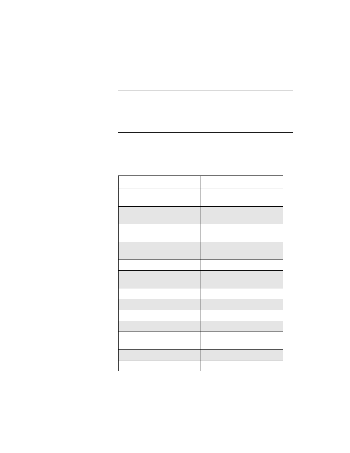
4. Use the appropriate VIs to specify the attributes of the operation.
These VIs are listed in Table 3-10.
Note: When you access a new D/A frame, the frame elements
contain default values. If the default value of a particular element is
suitable for your operation, you do not have to use the VI associated
with that element. Refer to Table 3-2 on page 3-6 for a list of the
default values of D/A frame elements.
Table 3-9. VIs Used for DMA-Mode
Analog Output Operations
Attribute VIs
1
Buffer
Number of Samples K_SetBuf
K_SetDMABuf
K_SetBufListAdd
K_SetBufListAdd
Buffering Mode K_SetContRun
K_ClrContRun
Start Channel K_SetChn
K_SetStartStopChn
Stop Channel K_SetStartStopChn
Gain K_SetG
K_SetStartStopG
Channel-Gain Array K_SetChnGAry
Pacer Clock Rate
External Clock Edge K_SetExtClkEdge
Trigger Source K_SetTrig
Trigger Type K_SetADTrig
Trigger Channel K_SetADTrig
Trigger Polarity K_SetADTrig
1
K_SetClkRate
K_SetDITrig
2
3-19
Page 76
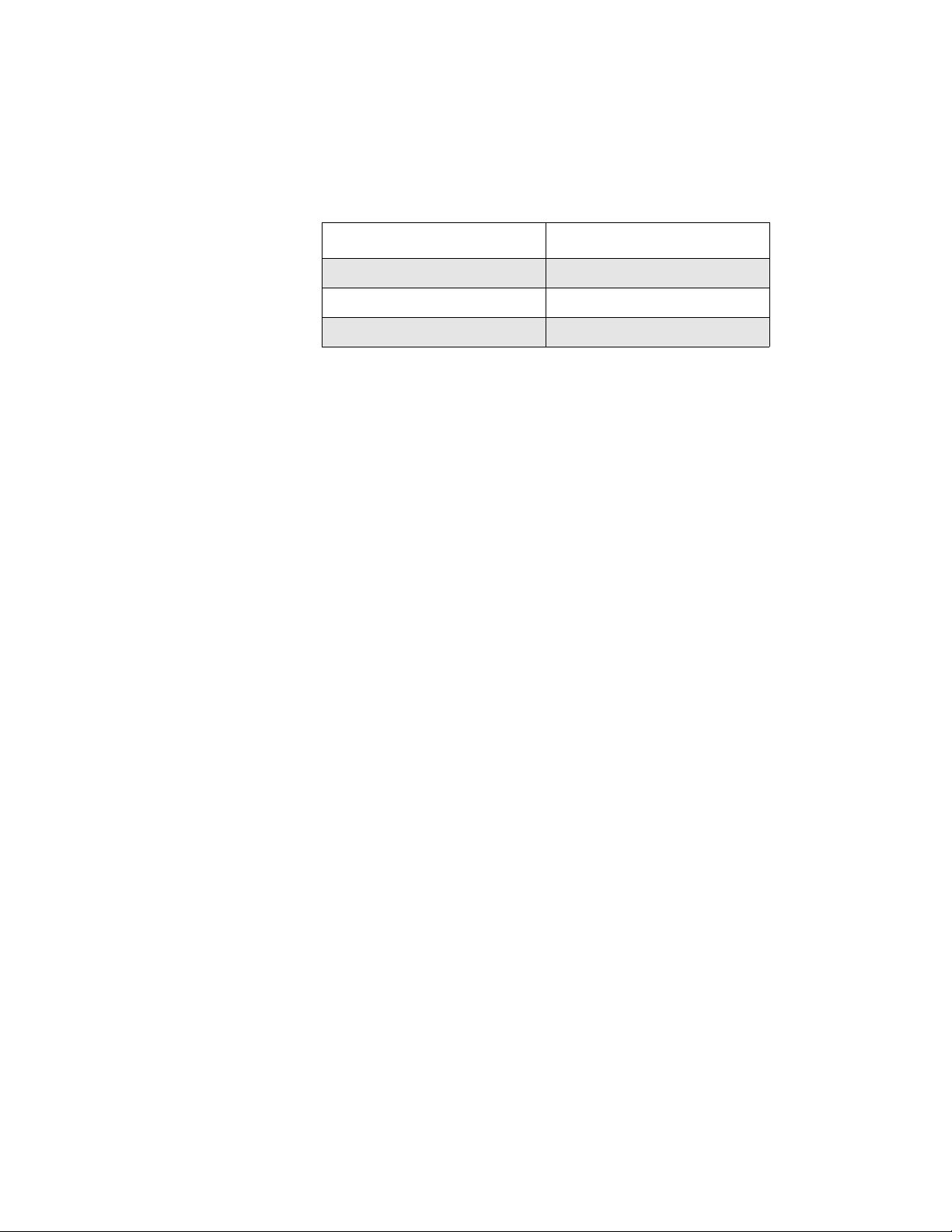
Table 3-9. VIs Used for DMA-Mode
Analog Output Operations (cont.)
Attribute VIs
Trigger Level K_SetADTrig
Trigger Hysteresis K_SetTrigHyst
Hardware Gate K_SetGate
Notes
1
This element must be set.
2
Use this VI to reset the value of this particular frame element to its
default setting without clearing the frame or getting a new frame.
5. Use K_MoveArrayToBuf to transfer the data from a LabVIEW
array to the allocated buffer.
6. Use K_DMAStart to start the DMA-mode operation.
7. Use K_DMAStatus to monitor the status of the DMA-mode
operation.
8. If you specified continuous buffering mode, use K_DMAStop to stop
the DMA-mode operation when the appropriate number of samples
has been written.
9. Use K_DMAFree to deallocate the buffer.
10. Use K_FreeFrame to return the frame you accessed in step 1 to the
pool of available frames.
Recycle Mode
For a recycle-mode analog output operation, perform the following tasks:
1. Use K_GetDAFrame to access a D/A frame.
2. Use K_IntAlloc or K_DMAAlloc to allocate the buffer dynamically
outside your program's memory area. The buffer must contain 2048
samples or fewer.
3. Use K_SetContRun to specify continuous buffering mode.
4. Use the appropriate VIs to specify the attributes of the operation.
These VIs are listed in Table 3-10.
3-20 Programming with the VI Driver
Page 77

Note: When you access a new D/A frame, the frame elements
contain default values. If the default value of a particular element is
suitable for your operation, you do not have to use the VI associated
with that element. Refer to Table 3-2 on page 3-6 for a list of the
default values of D/A frame elements.
Table 3-10. VIs Used for Recycle-Mode
Analog Output Operations
Attribute VIs
1
Buffer
Number of Samples K_SetBuf
Gain K_SetG
Channel-Gain Array K_SetChnGAry
Pacer Clock Rate
1
K_SetDMABuf
K_SetBufListAdd
K_SetBufListAdd
K_SetStartStopG
K_SetClkRate
External Clock Edge K_SetExtClkEdge
Trigger Source K_SetTrig
Trigger Type K_SetADTrig
K_SetDITrig
Trigger Channel K_SetADTrig
Trigger Polarity K_SetADTrig
Trigger Level K_SetADTrig
Trigger Hysteresis K_SetTrigHyst
Hardware Gate K_SetGate
Notes
1
This element must be set.
3-21
Page 78

5. Use K_MoveArrayToBuf to transfer the data from a LabVIEW
array to the allocated buffer.
6. Use K_IntStart or K_DMAStart to start the recycle-mode
operation.
7. Use K_IntStatus or K_DMAStatus to monitor the status of the
recycle-mode operation.
8. Use K_IntStop or K_DMAStop to stop the recycle-mode operation
when the appropriate number of samples has been written.
9. If you used K_IntAlloc to allocate the buffer, use K_IntFree to
deallocate the buffer; if you used K_DMAAlloc to allocate the
buffer, use K_DMAFree to deallocate the buffer.
10. Use K_FreeFrame to return the frame you accessed in step 1 to the
pool of available frames.
Digital I/O Operations
The following subsections describe the operation-specific programming
tasks required to perform single-mode and interrupt-mode digital I/O
operations.
Single Mode
For a single-mode digital I/O operation, use K_DIRead to read a single
digital input value or use K_DOWrite to write a single digital output
value. Specify the attributes of the operation as inputs to the VI.
3-22 Programming with the VI Driver
Page 79

Interrupt Mode
For an interrupt-mode digital I/O operation, perform the following tasks:
1. Use K_GetDIFrame to access a DI frame; use K_GetDOFrame to
access a DO frame.
2. Use K_IntAlloc to allocate the buffer in which to store the data to be
read or written.
3. Use the appropriate VIs to specify the attributes of the operation;
these VIs are listed in Table 3-11.
Note: When you access a new DI or DO frame, the frame elements
contain default values. If the default value of a particular frame
element is suitable for your operation, you do not have to use the VI
associated with that element. Refer to Table 3-3 on page 3-8 for a list
of the default values of DI frame elements; refer to Table 3-4 on page
3-9 for a list of the default values of DO frame elements.
Table 3-11. VIs Used for Interrupt-Mode
Digital Input and Digital Output Operations
Attribute VIs
1
Buffer
Number of Samples K_SetBuf
Buffering Mode K_SetContRun
Pacer Clock Rate
Notes
1
This element must be set.
2
Use this VI to reset the value of this particular frame element to its
default setting without clearing the frame or getting a new frame.
1
K_SetBuf
K_ClrContRun
K_SetClkRate
2
4. If you are performing a digital output operation, use
K_MoveArrayToBuf to transfer the data from a LabVIEW array to
the allocated buffer.
3-23
Page 80

5. Use K_IntStart to start the interrupt-mode operation.
6. Use K_IntStatus to monitor the status of the interrupt-mode
operation.
7. If you specified continuous buffering mode, use K_IntStop to stop the
interrupt-mode operation when the appropriate number of samples
has been written.
8. If you are performing a digital input operation, use
K_MoveBufToArray to transfer the data from the allocated buffer to
a LabVIEW array.
9. Use K_IntFree to deallocate the buffer.
10. Use K_FreeFrame to return the frame you accessed in step 1 to the
pool of available frames.
3-24 Programming with the VI Driver
Page 81

4
4
VI Reference
The DAS-1800 Series VIs are organized into the following functional
groups:
●
Initialization
Operation mode
●
●
Frame management
●
Memory management
Buffer address
●
Buffering mode
●
●
Conversion mode
Channel and gain
●
●
Clock
Trigger
●
●
Gate
●
Miscellaneous
The particular VIs associated with each group are listed in Table 4-1. The
remainder of the chapter presents detailed descriptions of each VI,
arranged in alphabetical order.
4-1
Page 82

Table 4-1. VIs by Functional Group
VI Functional Groups VI Name Page Number
Initialization K_OpenDriver page 4-54
K_CloseDriver page 4-11
K_GetDevHandle page 4-38
K_FreeDevHandle page 4-29
K_DASDevInit page 4-15
Operation Mode K_ADRead page 4-5
K_DAWriteGain page 4-16
K_DIRead page 4-18
K_DOWrite page 4-26
K_DMAStart page 4-21
K_DMAStatus page 4-22
K_DMAStop page 4-25
K_IntStart page 4-47
K_IntStatus page 4-48
K_IntStop page 4-51
Frame Management K_GetADFrame page 4-33
K_GetDAFrame page 4-37
K_GetDIFrame page 4-39
K_GetDOFrame page 4-40
K_FreeFrame page 4-30
K_ClearFrame page 4-10
4-2 VI Reference
Page 83

Table 4-1. VIs by Functional Group (cont.)
VI Functional Groups VI Name Page Number
Memory Management K_DMAAlloc page 4-19
K_DMAFree page 4-20
K_IntAlloc page 4-45
K_IntFree page 4-46
K_MoveArrayToBuf page 4-52
K_MoveBufToArray page 4-53
Buffer Address K_SetBuf page 4-62
K_SetDMABuf page 4-73
K_BufListAdd page 4-8
K_BufListReset page 4-9
Buffering Mode K_ClrContRun page 4-14
K_SetContRun page 4-70
Conversion Mode K_SetADFreeRun page 4-58
K_ClrADFreeRun page 4-13
K_SetSSH page 4-77
Channel and Gain K_SetChn page 4-64
K_SetStartStopChn page 4-78
K_SetG page 4-75
K_SetStartStopG page 4-80
K_AllocChnGAry page 4-7
K_FormatChnGAry page 4-27
K_FreeChnGAry page 4-28
K_SetChnGAry page 4-65
K_SetADCommonMode page 4-56
K_SetADConfig page 4-57
K_SetADMode page 4-59
4-3
Page 84

Table 4-1. VIs by Functional Group (cont.)
VI Functional Groups VI Name Page Number
Channel and Gain (cont.) K_GetADCommonMode page 4-31
K_GetADConfig page 4-32
K_GetADMode page 4-34
Clock K_SetClk page 4-66
K_SetClkRate page 4-68
K_SetExtClkEdge page 4-74
K_GetClkRate page 4-35
K_SetBurstTicks page 4-63
K_SetSync page 4-82
Trigger K_SetTrig page 4-83
K_SetADTrig page 4-60
K_SetTrigHyst page 4-84
K_SetDITrig page 4-71
K_SetAboutTrig page 4-55
K_ClrAboutTrig page 4-12
Gate K_SetGate page 4-76
Miscellaneous K_GetErrMsg page 4-41
K_GetVer page 4-43
K_GetShellVer page 4-42
For a description of the error information in the Error In and Error Out
parameters in this chapter, see page 2-3.
4-4 VI Reference
Page 85

0
0
0
N
0
K_ADRead
Purpose
Description
Parameters
U32
U16
Reads a single analog input value.
This VI reads the analog input channel represented by Input Channel on
the board specified by Board Handle at the gain represented by Gain
Code , and stores the raw count in Input Value .
Board Handle
Input
Gain Code
Board Handle
Input Channel
Error In
K_ADRead
Handle associated with the board.
Analog input channel.
Input Value
Error Out
Valid values are shown below:
Valid Channel Numbers
Board Configuration Differential Single-ended
U16
I16
DAS-1800AO Series board
DAS-1800AO Series board with
EXP-1800s attached
Gain Code
Valid values:
to 3 = DAS board channels
to 7 = EXP-1800 channels
Input Value
Error In
Acquired analog input value.
Error information.
to 70
Not applicable
to 15
to 15( N + 1)
4-5
Page 86

K_ADRead (cont.)
Remarks
See Also
Error Out
Refer to Table 2-2 on page 2-7 for the gain and input ranges associated
with each gain code.
Refer to Appendix B for converting the ra w count stored in Input V alue to
voltage.
K_DMAStart, K_IntStart
Error information.
4-6 VI Reference
Page 87

K_AllocChnGAry
Purpose
Description
Parameters
U32
U16
Allocates space for a channel-gain array.
For the operation defined by Frame Handle, this VI uses the number of
entries in Number of Entries to allocate space for a channel-gain array and
creates a handle for the array in ChnGAry Handle .
Frame Handle
Number of Entries
Error In
Frame Handle
Number of Entries
K_AllocChnGAry
Handle to the frame that defines the operation.
Number of channel-gain pairs in the
ChnGAry
Handle
Error Out
channel-gain array.
ChnGAry Handle
Handle associated with the allocated
channel-gain array.
Remarks
See Also
Error In
Error Out
Error information.
Error information.
Refer to page 2-12 for information on setting up a channel-gain array for
analog input operations: refer to page 2-27 for information on setting up a
channel-gain array for analog output operations.
K_FormatChnGAry, K_FreeChnGAry, K_SetChnGAry
4-7
Page 88

K_BufListAdd
Purpose
Description
Parameters
U32
U32
U32
Adds a buffer to the list of multiple buffers.
For the operation defined by Frame Handle , this VI adds the buffer at the
address pointed to by Buffer Address to the list of multiple buffers; the
number of samples in the buffer is specified in Number of Samples .
Frame Handle
Buffer Address
Number of Samples
Error In
Frame Handle
Buffer Address
Number of Samples
Error In
K_BufListAdd
Handle to the frame that defines the operation.
Starting address of buffer.
Number of samples in the buffer.
Error information.
Error Out
Remarks
Error Out
The driver supports multiple buffers for analog input and analog output
Error information.
operations. Before you add the buffer to the multiple-b uf fer list, you must
allocate the buffer dynamically using K_IntAlloc or K_DMAAlloc .
Make sure that you add buffers to the multiple-buffer list in the order in
which you want to use them. The first buffer you add is Buffer 1, the
second buffer you add is Buffer 2, and so on. You can add up to 149
buffers. You can use K_IntStatus or K_DMAStatus to determine which
buffer is currently in use.
See Also
4-8 VI Reference
K_BufListReset, K_DMAAlloc, K_IntAlloc
Page 89

K_BufListReset
Purpose
Description
Parameters
U32
Remarks
Clears the list of multiple buffers.
For the operation defined by Fr ame Handle, this VI clears all b uffers from
the list of multiple buffers.
Frame Handle
Error In
K_BufListReset
Error Out
Frame Handle Handle to the frame that defines the operation.
Error In Error information.
Error Out Error information.
This VI does not deallocate the buffers in the list of multiple buffers. If
dynamically allocated buffers are no longer needed, you can use
K_IntFree or K_DMAFree to free the buf fers before resetting the b uf fer
list.
See Also
K_DMAFree, K_IntFree, K_SetBuf, K_SetDMABuf
4-9
Page 90

K_ClearFrame
Purpose
Description
Parameters
U32
Remarks
Sets the elements of a frame to their default values.
This VI sets the elements of the frame specified by Frame Handle to their
default values.
Frame Handle
Error In
K_ClearFrame
Error Out
Frame Handle Handle to the frame that defines the operation.
Error In Error information.
Error Out Error information.
For the default values of the elements of frames, refer to the following
tables:
Frame Type See
A/D frames Table 3-1 on page 3-4
D/A frames Table 3-2 on page 3-6
DI frames Table 3-3 on page 3-8
DO frames Table 3-4 on page 3-9
See Also
4-10 VI Reference
K_GetADFrame, K_GetDAFrame, K_GetDIFrame, K_GetDOFrame
Page 91

K_CloseDriver
Purpose
Description
Parameters
U32
Remarks
Closes a previously initialized Keithley DAS VI Driver.
This VI frees the driver handle specified by Driver Handle and closes the
associated use of the VI Driver. This VI also frees all board handles and
frame handles associated with Driver Handle.
Driver Handle
Error In
K_CloseDriver
Error Out
Driver Handle Driver handle you want to free.
Error In Error information.
Error Out Error information.
If Driver Handle is the last driver handle specified for the VI Driver, the
driver is shut down and unloaded.
See Also
K_FreeDevHandle
4-11
Page 92

K_ClrAboutTrig
Purpose
Description
Parameters
U32
Remarks
Disables the about trigger for an analog input operation.
This VI disables the about trigger for the operation defined by Frame
Handle.
Frame Handle
Error In
K_ClrAboutTrig
Error Out
Frame Handle Handle to the frame that defines the operation.
Error In Error information.
Error Out Error information.
K_GetADFrame and K_ClearFrame also disable the about trigger.
See Also
4-12 VI Reference
K_ClearFrame, K_GetADFrame, K_SetAboutTrig
Page 93

K_ClrADFreeRun
Purpose
Description
Parameters
U32
Remarks
Sets paced conversion mode for an analog input operation.
This VI sets the conversion mode for the operation defined by Frame
Handle to paced mode and sets the Conversion Mode element in the
frame accordingly.
Frame Handle
Error In
K_ClrADFreeRun
Error Out
Frame Handle Handle to the frame that defines the operation.
Error In Error information.
Error Out Error information.
K_GetADFrame and K_ClearFrame also enable paced conversion
mode.
See Also
K_ClearFrame, K_GetADFrame, K_SetADFreeRun
4-13
Page 94

K_ClrContRun
Purpose
Description
Parameters
U32
Remarks
Sets single-cycle buffering mode.
This VI sets the buffering mode for the operation defined by Frame
Handle to single-cycle mode and sets the Buffering Mode element in the
frame accordingly.
Frame Handle
Error In
K_ClrContRun
Error Out
Frame Handle Handle to the frame that defines the operation.
Error In Error information.
Error Out Error information.
K_GetADFrame, K_GetDAFrame, K_GetDIFrame,
K_GetDOFrame, and K_ClearFrame also enable single-cycle buf fering
mode. For more information on buffering modes, refer to the following
pages:
Operation See
Analog input page 2-16
Analog output page 2-30
Digital I/O page 2-39
See Also
4-14 VI Reference
K_SetContRun
Page 95

K_DASDevInit
Purpose
Description
Parameters
U32
Reinitializes a board.
This VI stops all current operations and resets the board specified by
Board Handle and the driver to their power-up states.
Board Handle
Error In
K_DASDevInit
Error Out
Board Handle Handle associated with the board.
Error In Error information.
Error Out Error information.
4-15
Page 96

K_DAWriteGain
Purpose
Description
Parameters
U32
U16
U32
Writes a single analog output value.
For the operation defined by Board Handle, this VI writes the single
analog output value Output Value to the channel represented by Output
Channel. The output range is specified by Gain Code.
Gain Code
Board Handle
Output Channel
Output Value
Error In
K_DAWriteGain
Error Out
Board Handle Handle to the board that defines the operation.
Output Channel Analog output channel.
Valid values: 0 for DAC 0
1 for DAC 1
Output Value Analog output value.
Valid values:
−2,048 to 2,047
U16
Gain Code Valid values: 0 for ±5 V D/A range
1 for ±10 V D/A range
Error In Error information.
Error Out Error information.
Remarks
The value of Output Value comprises only the least significant 12 bits.
Refer to page 2-26 for more information on output ranges and their
corresponding gain codes.
Refer to Appendix B for converting a voltage value to a raw count.
4-16 VI Reference
Page 97

K_DAWriteGain (cont.)
See Also
K_IntStart
4-17
Page 98

K_DIRead
Purpose
Description
Parameters
U32
U16
U16
Reads a single digital input value.
This VI reads the v alues of all digital input lines on the board specified by
Board Handle, and stores the value in Input Value.
Board Handle
Input Channel
Error In
K_DIRead
Input Value
Error Out
Board Handle Handle associated with the board.
Input Channel Digital input channel.
Valid value: 0
Input Value Digital input value.
Error In Error information.
Error Out Error information.
Remarks
The acquired digital value in Input V alue is stored in bits 0, 1, 2, and 3; the
values in the remaining bits of Input V alue are not defined. Refer to Figure
on page 2-36 for more information.
See Also K_IntStart
4-18 VI Reference
Page 99

K_DMAAlloc
Purpose
Description
Parameters
U32
U32
U32
Allocates a buffer for a DMA-mode operation.
For the operation defined by Frame Handle, this VI allocates a buffer of
the size Number of Samples. On return, Buffer Address contains the
address of a buffer that is suitable for a DMA-mode operation and Buffer
Handle is the handle associated with the buffer.
Frame Handle
Number of Samples
Error In
K_DMAAlloc
Buffer Address
Buffer Handle
Error Out
Frame Handle Handle to the frame that defines the operation.
Number of Samples Number of samples.
Valid values: 1 to 65,536
Buffer Address Starting address of the allocated buffer.
Remarks
See Also
U16
Buffer Handle Handle associated with the allocated buffer.
Error In Error information.
Error Out Error information.
Use K_SetDMABuf or K_BufListAdd to assign Buffer Address to the
frame that defines the operation. Buffer Handle, as returned by this VI, is
later used to free the allocated memory block when used with
K_DMAFree.
K_DMAFree, K_SetDMABuf, K_BufListAdd
4-19
Page 100
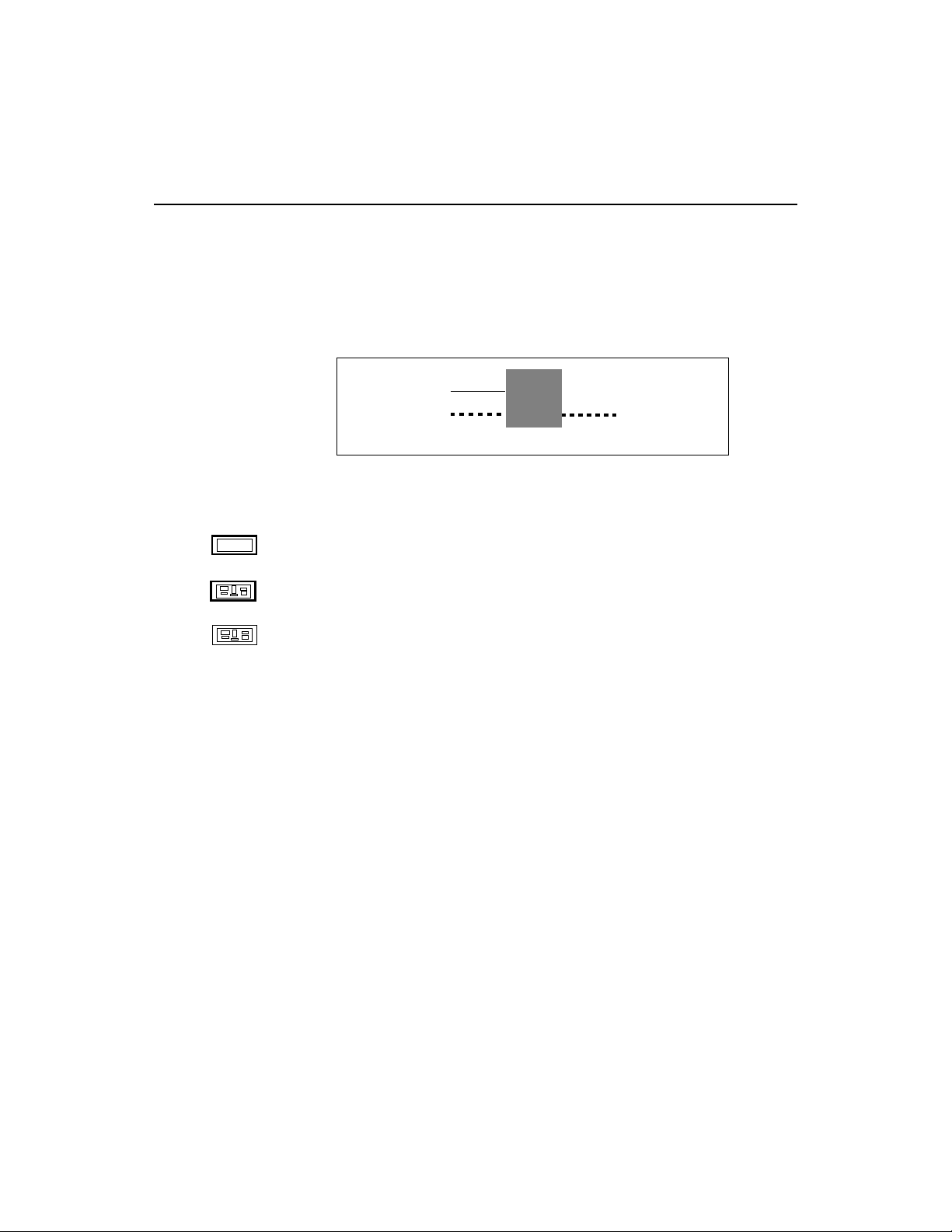
K_DMAFree
Purpose
Description
Parameters
U16
See Also
Frees a buffer allocated for a DMA-mode operation.
This VI frees the buffer specified by Buffer Handle; the buffer was
previously allocated dynamically using K_DMAAlloc.
Buffer Handle
Error In
K_DMAFree
Error Out
Buffer Handle Handle to DMA buffer.
Error In Error information.
Error Out Error information.
K_DMAlloc, K_SetDMABuf, K_BufListAdd
4-20 VI Reference
 Loading...