

Page 1

tek.com/keithley
Model DAQ6510
Data Acquisition and Multimeter System
User’s Manual
DAQ6510-900-01 Rev. B / August 2019
*PDAQ6510-900-01B*
DAQ6510-900-01B
Page 2

Model DAQ6510
Data Acquisition and Multimeter System
User's Manual
Page 3

© 2019, Keithley Instruments, LLC
Cleveland, Ohio, U.S.A.
All rights reserved.
Any unauthorized reproduction, phot ocopy, or use of the information herein, in whole or in part,
without the prior written approval of Keithley Instruments, LLC, is strictly prohibited.
These are the original instructions in English.
TSP®, TSP-Link®, and TSP-Net® are trademarks of Keithley Instruments, LLC. All Keithley
Instruments product names are trademarks or r egistered trademarks of Keithley Instrum ents, LLC.
Other brand names are trademarks or registered trademarks of their respective holders.
The Lua 5.0 software and associated documentation files are copyright © 1994 - 2015, Lua.or g,
PUC-Rio. You can access terms of license for the Lua software and associated documentation at
the Lua licensing site (http://www.lua.org/license.html).
Microsoft, Visual C++, Excel, and Windows are either registered trademarks or trademarks of
Microsoft Corporation in the United States and/or other countries.
Document number: DAQ6510-900-01 Rev. B / August 2019
Page 4

Safety precautions
The following safety precautions should be observed before using this product and any associated instrumentation. Although
some instruments and accessories would normally be used with nonhazardous voltages, there are situations where hazardous
conditions may be present.
This product is intended for use by personnel who recognize shock hazards and are familiar with the safety precautions required
to avoid possible injury. Read and follow all installation, operation, and maintenance information carefully before using the
product. Refer to the user documentation for complete product specifications.
If the product is used in a manner not specified, the protection provided by the produc t warranty may be impaired.
The types of product users are:
Responsible body is the individual or group responsible for the use and maintenance of equipment, for ensuring that the
equipment is operated within its specifications and operating limits, and for ensuring that operators ar e adequately trained.
Operators use the product for its i ntended function. They must be trained in electrical safety procedures and proper use of the
instrument. They must be protected from electric shock and contact with h azardous live circuits.
Maintenance personnel perform routine procedures on the product to keep it operating properly, for example, setting the line
voltage or replacing consumable materials. Maintenance procedures ar e described in the user documentation. The procedures
explicitly state if the operator may perform them. Otherwise, they should be performed only by service personnel.
Service personnel are trained to work on live cir c ui ts, perform safe installations, and r epair products. Only properly trained
service personnel may perform ins tallation and service procedures.
Keithley Instruments products are des igned for use with electrical signals that are measurement, control, and data I/O
connections, with low transient ov ervoltages, and must not be directly conn ected to mains voltage or to voltage sourc es with high
transient overvoltages. Measu rement Category II (as referenced in IEC 60664) connections require protection for high transient
overvoltages often associated with local AC mains connections. Certai n K ei thley Instruments measuring instrum ents may be
connected to mains. These instruments will be marked as category II or higher .
Unless explicitly allowed in the specif i cations, operating manual, and instrument labels, do not connect any instr ument to mains.
Exercise extreme caution when a shock hazard is present. Lethal voltage m ay be present on cable connector jacks or test
fixtures. The American National S tandards Institute (ANSI) states that a shock hazard exists when voltage levels greater than
30 V RMS, 42.4 V peak, or 60 VDC are present. A good safety practice is to expect that hazardous voltage is present in any
unknown circuit before measur i ng.
Operators of this product must be protec ted from electric shock at all times. The responsible body must ensure that operators
are prevented access and/or insulated from every connection point. In some c ases, connections must be exposed to potential
human contact. Product operators i n these circumstances must be trained to pr otect themselves from the risk of electric shock. If
the circuit is capable of operating at or above 1000 V, no conductive part o f the circuit may be exposed.
Do not connect switching cards direc tly to unlimited power circuits. They are intended to be used with impedance-limited
sources. NEVER connect switching cards directly to AC mains. When conn ec ting sources to switching cards , install protective
devices to limit fault current and v ol tage to the card.
Before operating an instrument, ensure that the line cord is connected to a properly-grounded power receptacle. Inspect the
connecting cables, test leads, and j umpers for possible wear, cracks, or breaks before each use.
When installing equipment where ac cess to the main power cord is restricted, such as rack mounting, a separate main input
power disconnect device must be provided in close proximity to the equipment and within easy reach of the operator.
For maximum safety, do not touch the product, test cables, or any other instruments while power is applied to the circuit under
test. ALWAYS remove power from the entire test system and discharge any ca pac i tors before: connecting or disconnecting
cables or jumpers, installing or rem oving switching cards, or making int er nal changes, such as installing or removing jumpers.
Do not touch any object that could provide a current path to the common side of the c i rcuit under test or power line (e arth)
ground. Always make measurements with dry hands while standing on a dry, insulated surface capable of withstandin g the
voltage being measured.
Page 5

For safety, instruments and accessories must be used in accordance with the operating instructions. If the instruments or
accessories are used in a manner not s pecified in the operating instructions, the protection provided by the equipment may be
impaired.
Do not exceed the maximum signal lev els of the instruments and accessories . Maximum signal levels are defined in the
specifications and operating inf or mation and shown on the instrument panels, test fixture panels, and switching cards.
When fuses are used in a product, replac e with the same type and rating for continued protection against fire hazard.
Chassis connections must only be used as shield connections for measuring c i rcuits, NOT as protective earth (s afety ground)
connections.
If you are using a test fixture, keep the lid closed while power is applied to the device under test. Safe operation re quires the use
of a lid interlock.
If a
screw is present, connect it to prot ective earth (safety ground) using the wire r ecommended in the user documentation.
The symbol on an instrument means caution, risk of hazard. The user must refer to t he operating instructions located in the
user documentation in all cases where the symbol is marked on the instrument .
The
symbol on an instrument means warning, risk of electric shock. Use standard saf ety precautions to avoid personal
contact with these voltages.
The
symbol on an instrument shows that the sur face may be hot. Avoid personal contact to prevent burns.
The symbol indicates a connection termin al to the equipment frame.
If this
symbol is on a product, it indicates th at mercury is present in the display l am p. Please note that the lamp must be
properly disposed of according to federal, state, and local laws.
The WARNING heading in the user documentation explains hazards that might result in personal injury or death. Always read
the associated information very car efully before performing the indicated procedure.
The CAUTION heading in the user documentation explains hazards that could damage the inst rument. Such damage may
invalidate the warranty.
The CAUTION heading with the
symbol in the user documentation explains hazards that could result in moderate or minor
injury or damage the instrument. Always read the associated information very carefully before performing the indicated
procedure. Damage to the instrument may invalidate the warranty.
Instrumentation and accessories shall not be connected to humans.
Before performing any maintenance, disconnect the line cord and all test cables.
To maintain protection from electric shock and fire, replacement components in mains circuits — including the power
transformer, test leads, and input j ac ks — must be purchased from Keithley I ns truments. Standard fuses with appli c able national
safety approvals may be used if the rating and type are the same. The detachable m ains power cord provided with the
instrument may only be replaced with a similarly rated power cord. Other c omponents that are not safety-related may be
purchased from other suppliers as long as they are equivalent to the original c omponent (note that selected parts should be
purchased only through Keithley Inst ruments to maintain accuracy and fun ctionality of the product). If you are unsure about the
applicability of a replacement c om ponent, call a Keithley Instruments office for information.
Unless otherwise noted in product-specific literature, Keithle y I ns truments instruments are designed t o operate indoors only, in
the following environment: Altitude at or below 2,000 m (6,562 ft); temperature 0 °C to 50 °C (32 °F to 122 °F); and pollu tion
degree 1 or 2.
To clean an instrument, use a cloth dampened with deionized water or mild, water-based cleaner. Clean the exterior of the
instrument only. Do not apply cleaner directly to the instrument or allow liquids to enter or spill on the instrument. Products that
consist of a circuit board with no case or chassis (e.g., a data acquisition board for installation into a computer ) should never
require cleaning if handled acc or ding to instructions. If the board becomes contaminated and operation is affected, the board
should be returned to the factory for proper cleaning/servicing.
Safety precaution revision as of J une 2017.
Page 6

Table of contents
Introduction ................................................................................................................ 1-1
Welcome .............................................................................................................................. 1-1
Introduction to this manual ................................................................................................... 1-1
Extended warranty ............................................................................................................... 1-2
Contact information .............................................................................................................. 1-2
Documentation set ............................................................................................................... 1-2
Organization of manual sections .......................................................................................... 1-3
Application examples ........................................................................................................... 1-3
Front-panel overview ................................................................................................. 2-1
Front-panel overview ............................................................................................................ 2-1
Instrument power ................................................................................................................. 2-3
Connect the power cord ............................................................................................................ 2-3
Turn the DAQ6510 on or off ...................................................................................................... 2-4
Touchscreen display ............................................................................................................ 2-4
Select items on the touchscreen ............................................................................................... 2-5
Scroll bars ................................................................................................................................. 2-5
Enter information ....................................................................................................................... 2-6
Adjust the backlight brightnes s and dimmer .............................................................................. 2-6
Review event messages ........................................................................................................... 2-7
Interactive swipe screens ..................................................................................................... 2-7
Swipe screen heading bar ......................................................................................................... 2-7
FUNCTIONS swipe screen ....................................................................................................... 2-9
SETTINGS swipe screen .......................................................................................................... 2-9
STATISTICS swipe screen ...................................................................................................... 2-10
SECONDARY swipe screen .................................................................................................... 2-10
USER swipe screen ................................................................................................................ 2-11
GRAPH swipe screen ............................................................................................................. 2-12
SCAN swipe screen ................................................................................................................ 2-12
Menu overview ................................................................................................................... 2-14
Channel menu ......................................................................................................................... 2-15
Measure Menu ........................................................................................................................ 2-15
Views menu ............................................................................................................................. 2-16
Trigger menu ........................................................................................................................... 2-16
Scripts menu ........................................................................................................................... 2-17
System menu .......................................................................................................................... 2-18
Using a remote interface ........................................................................................... 3-1
Remote communications interfaces ..................................................................................... 3-1
Supported remote interfaces ................................................................................................ 3-2
LAN communications ........................................................................................................... 3-3
Set up LAN communications on the instrument ........................................................................ 3-3
Set up LAN communications on the computer .......................................................................... 3-5
USB communications ........................................................................................................... 3-6
Page 7

Table of con
User's Manual
tents DAQ6510 Data Acquisition and Multim eter System
Connect a computer to the DAQ6510 using USB ..................................................................... 3-6
Communicate with the instrument ............................................................................................. 3-7
GPIB communications ........................................................................................................ 3-11
Install the KTTI-GPIB accessory card ..................................................................................... 3-11
Set the GPIB address ............................................................................................................. 3-14
RS-232 ............................................................................................................................... 3-14
Install the KTTI-RS232 accessory card ................................................................................... 3-15
TSP-Link ............................................................................................................................ 3-17
Install the KTTI-TSP accessory card ....................................................................................... 3-17
Using the web interface ...................................................................................................... 3-19
Connect to the instrument web interface ................................................................................. 3-19
LAN troubleshooting suggestions ............................................................................................ 3-19
Web interface Home page....................................................................................................... 3-20
Identify the instrument ............................................................................................................. 3-21
Determining the command set you will use ....................................................................... 3-21
Making basic front-panel measurements ................................................................ 4-1
Introduction .......................................................................................................................... 4-1
Equipment required for this example ................................................................................... 4-1
Device connections .............................................................................................................. 4-2
Basic front-panel measurements ......................................................................................... 4-2
View measurement data ...................................................................................................... 4-3
Scanning temperature using thermocouples .......................................................... 5-1
Introduction .......................................................................................................................... 5-1
Equipment required .............................................................................................................. 5-1
Device connections .............................................................................................................. 5-1
Thermocouple temperature scanning .................................................................................. 5-3
Using the front panel ................................................................................................................. 5-4
Using SCPI commands ............................................................................................................. 5-5
Using TSP commands .............................................................................................................. 5-5
Test results ................................................................................................................................ 5-6
Scanning low-level DCV ............................................................................................ 6-1
Introduction .......................................................................................................................... 6-1
Equipment required .............................................................................................................. 6-1
Device connections .............................................................................................................. 6-2
Scanning low-level DCV ....................................................................................................... 6-4
Using the front panel ................................................................................................................. 6-5
Using SCPI commands ............................................................................................................. 6-5
Using TSP commands .............................................................................................................. 6-7
Scanning resistors using 4W measurement ........................................................... 7-1
Introduction .......................................................................................................................... 7-1
Page 8

DAQ6510
of contents
Data Acquisition and Multimeter System User's Manual Table
Equipment required .............................................................................................................. 7-2
Device connections .............................................................................................................. 7-2
Scanning resistors using 4-wire measurement s .................................................................. 7-4
Using the front panel ................................................................................................................. 7-4
Using SCPI commands ............................................................................................................. 7-5
Using TSP commands .............................................................................................................. 7-5
Test results ................................................................................................................................ 7-6
Mixed function multi-channel scanning ................................................................... 8-1
Introduction .......................................................................................................................... 8-1
Equipment required .............................................................................................................. 8-2
Device connections .............................................................................................................. 8-2
Mixed function multi-channel scanning ................................................................................ 8-4
Using the front panel ................................................................................................................. 8-4
Using SCPI commands ............................................................................................................. 8-5
Using TSP commands .............................................................................................................. 8-6
Test results ................................................................................................................................ 8-7
Speed scanning for increased test throughput ...................................................... 9-1
Introduction .......................................................................................................................... 9-1
Equipment required .............................................................................................................. 9-2
Device connections .............................................................................................................. 9-2
Speed scanning for increased production test t hroughput .................................................. 9-3
Using SCPI commands ............................................................................................................. 9-4
Using TSP commands .............................................................................................................. 9-6
Test results ................................................................................................................................ 9-7
Prescan monitor ....................................................................................................... 10-1
Introduction ........................................................................................................................ 10-1
Equipment required ............................................................................................................ 10-1
Device connections ............................................................................................................ 10-1
Using the Monitor Measurement feature ............................................................................ 10-3
Using the front panel ............................................................................................................... 10-3
Using SCPI commands ........................................................................................................... 10-4
Using TSP commands ............................................................................................................ 10-5
Troubleshooting/FAQ .............................................................................................. 11-1
About this section ............................................................................................................... 11-1
Where can I find updated drivers? ..................................................................................... 11-1
Is there any software to help me get started? .................................................................... 11-2
How do I upgrade the firmware? ........................................................................................ 11-2
Why can't the DAQ6510 read my USB flash drive? ........................................................... 11-2
How do I change the command set? ................................................................................. 11-4
Page 9

Table of contents
User's Manual
DAQ6510 Data Acquisition and Multimeter System
How do I save the present state of the instrument? .......................................................... 11-5
Why did my settings change? ............................................................................................ 11-2
How do I save what is displayed on the screen? ............................................................... 11-5
What is the ethernet port number? .................................................................................... 11-5
Next steps ................................................................................................................. 12-1
Additional DAQ6510 information ........................................................................................ 12-1
Page 10

Application examples ............................................................... 1-3
In this section:
Welcome
Section 1
Introduction
Welcome .................................................................................. 1-1
Introduction to this manual ....................................................... 1-1
Extended warranty ................................................................... 1-2
Contact information .................................................................. 1-2
Documentation set ................................................................... 1-2
Organization of manual sections .............................................. 1-3
Thank you for choosing a Keithley Instruments product. The DAQ6510 is a 6½ digit graphical
sampling data-acquisition (DAQ) system t hat provides high-speed digitizing and a large graphical
color touchscreen display. This DAQ offers a bro ad range of measurement capabilities, including 15
measurement functions. In addition to indust ry-leading DC accuracies, functions such as capacitance,
3 A current, and 16-bit current and voltage digit izing are included. Tying all these features together is
a large 5-inch color touchscreen display that bring s users an unprecedented combination of data
visualization and interaction, enabling u sers to gain deeper insight into their measurements.
The DAQ6510 provides superior measurement accuracy and the speed necessary for a broad range
of applications including system, production testing, and benchtop applications. The DAQ6510 meets
application requirements for production engineers, research and development engineers, test
engineers, and scientists.
Introduction to this manual
This manual provides detailed applications to help you achieve success with your Keithley
Instruments DAQ6510. It also provides information about the basics of the front panel to familiarize
you with the instrument.
Each application includes an overview, foll owed by instructions to complete the application using t he
®
front panel, SCPI code, TSP
code, or Keithley KickStart Software.
More information about the commands that are used in these applications is available. Refer to the
SCPI and TSP command reference sections of the Model DAQ6510 Reference Manual. This manual
is available at tek.com/keithley
.
Page 11

Section
User's Manual
1: Introduction DAQ6510 Data Acquisition and Multim eter System
Extended warranty
Additional years of warranty coverage are available on many products. These valuable contracts
protect you from unbudgeted service expenses and p rovide additional years of protection at a fraction
of the price of a repair. Extended warranties are av ailable on new and existing products. Contact your
local Keithley Instruments office, sales partner, or distributor for details.
Contact information
If you have any questions after you review the information in this documentation, please contact your
local Keithley Instruments office, sales partner, or distributor. You can also call the corporate
headquarters of Keithley Instruments (toll -f ree inside the U.S. and Canada only) at 1-800-935-5595,
or from outside the U.S. at +1-440-248-0400. For worldwide contact numbers, visit the
Instruments website (tek.com/keithley).
Documentation set
Keithley
The documentation for the DAQ6510 is available on the Keithley Instruments website
(tek.com/keithley). The documentation includes:
• Quick Start Guide: Provides unpacking instructio ns, describes basic connections, reviews basic
operation information, and provides a quick te st procedure to ensure the instrument is
operational.
• User’s Manual: Provides application exam pl es that you can use as a starting point to create your
own applications.
• Reference Manual: Includes advanced operation topics, maintenance information,
troubleshooting procedures, and in-depth descriptions of programming commands.
• Accessories information: Documentation for accessories that are available for the DAQ6510.
For the latest drivers and additional support information, see tek.com/keithley
.
1-2 DAQ6510-900-01 Rev. B / August 2019
Page 12

DAQ6510
Introduction
Data Acquisition and Multimeter System User's Manual Section 1:
Organization of manual sections
This manual is organized into the following section s:
• Using the front-panel interface: (on page 2-1) Describes the basics of using the front-panel
interface.
• Using a remote interface: (on page 3-1) Describes t he basics of remote communications and
using the instrument web interface.
• Application examples: (on page 1-3) Provides detailed examples of how to use the DAQ6510 in
some typical situations.
• Troubleshooting FAQs: (on page 11-1) Provide s answers to frequently asked questions to help
you troubleshoot common problems encount ered with the DAQ6510.
• Next steps: (on page 12-1) Provides information about additional resources that can help you use
the DAQ6510.
The PDF version of this manual contains bookmar ks for each section. The manual sections are also
listed in the Table of Contents at the beginning of thi s manual.
For more information about bookmarks, see Adobe
Application examples
This manual provides application exampl es t hat show you how to perform tests from either the front
panel or over a remote interface. The applications include:
• Making basic front-panel measurements: (on pa ge 4-1) Shows the basic measure functionality
using a single DAQ6510 and a two-terminal device under test.
• Scanning temperature using thermocouples: (on page 5-1) Shows how to use the DAQ6510 to
log thermocouple-based temperature measur em ent scans.
• Scanning low-level DCV: (on page 6-1) Shows how to use the DAQ6510 to accurately measure
DC voltage in a variety of ranges.
• Scanning resistors using 4-W measurement: (on page 7-1) Shows how to use the DAQ6510 to
accurately measure resistance devices.
• Mixed function multi-channel scanning: ( on page 8-1) Shows how to use the DAQ6510 to perform
complex multi-channel, mixed function scanning in a production-test environment.
• Speed scanning for increased test throughput: (on page 9-1) Shows how selecting the right
multiplexer module can increase your productivity by reducing overall test time.
®
Acrobat® or Reader® help.
• Prescan monitor: (on page 10-1) Shows how to conf igure the DAQ6510 to delay its scanning
function until the testing environment has reac hed a specific temperature.
DAQ6510-900-01 Rev. B / August 2019 1-3
Page 13

Menu overview ....................................................................... 2-14
Turns the instrument on or off. T o turn the instrument on, press
amber when turned off.
Returns the display to the home scr een.
Opens the main menu. Press the icons on t he main menu to open
In this section:
Front-panel overview ................................................................ 2-1
Instrument power ..................................................................... 2-3
Touchscreen display ................................................................ 2-4
Interactive swipe screens ......................................................... 2-7
Front-panel overview
The front panel of the DAQ6510 is shown below. Descriptions of the controls on the front panel follow
the figure.
Section 2
Front-panel overview
POWER switch
HOME key
Figure 1: DAQ6510 front panel
the power switch. To turn it off, pres s and hold the power switch.
The LED is green when the instrument is on and the LED is
MENU key
channel, measure, views, trigger, scripts, and system screens.
For details, refer to Menu overv i ew (on page 2-14).
Page 14

Section
User's Manual
Opens a menu of of preconfigured TSP scripts with a graphical
user interface.
Opens help for the area or item that is selected on the display. If
help, hold the on-screen button while pressing the HELP key.
Saves reading buffer data and scr een snapshots to a USB flash
drive.
The DAQ6510 has a high-resolution, five-inc h color touchscreen
Touchscreen display (on page 2-4) for details.
Selects the highlighted choice or allows you to edit the selected
field.
Returns to the previous screen or closes a dialog box. For
to the main menu screen.
function name on the screen.
Accesses trigger-related settings and operations. The action of
DAQ6510 Reference Manual.
Use the SENSE HI and SENSE LO terminals and the INPUT
INPUT terminals
Use the INPUT HI and INPUT LO terminals for all measurements
AMPS
Use the AMPS connection with the INPU T LO terminal to
Activates the terminals on the front or rear panel. Selecting the
the amber LED is visible.
2: Front-panel overview DAQ6510 Data Acquisition and Multimeter System
APPS key
HELP key
USB port
Touchscreen
ENTER key
EXIT key
FUNCTION key
TRIGGER key
SENSE terminals
there is no selection when you press the HELP key, it displays
overview information for the screen you are viewing. To display
drive. You can also store and retrieve scripts to and from a USB
flash drive. The flash drive must be formatted as a FAT or FAT32
display. The touchscreen accesses swipe screens and menu
options. You can access additional screens by pressing the
front-panel MENU, APPS, and FUNCTION keys. Refer to
example, press the EXIT key when the main m enu is displayed to
return to the home screen. When you are v iewing a subscreen
(for example, the Event Log screen), press the EXIT key to return
Displays instrument functions. To select a function, touch the
the TRIGGER key depends on the instrument state. For details,
see "Switching between measurement methods" in the Model
terminals with the 4-wire resistanc e, 3-wire and 4-wire RTD
temperature, and DC voltage ratio functions.
TERMINALS
switch
2-2 DAQ6510-900-01 Rev. B / August 2019
except current.
measure ≤3A DC or AC
current.
RMS
rear panel provides the proper connections to an inserted
switching module. When the front-panel terminals are active, the
green LED is visible. When the rear-panel terminals are active,
Page 15

DAQ6510
panel overview
Data Acquisition and Multimeter System User's Manual Section 2: Front-
Instrument power
Follow the steps below to connect the DAQ6510 to line power and turn on the instrument. The
DAQ6510 operates from a line voltage of 100 V to 240 V at a frequency of 50 Hz, 60 Hz, or 400 Hz. It
automatically senses line frequency. Make sur e the operating voltage in your area is compatible.
The fuse is set to the expected voltage at the factory. M ake sure that the correct line voltage is
displayed on the power module. See "Line voltage v erification" in the Model DAQ6510 Reference
Manual for more information.
You must turn on the DAQ6510 and allow it to warm up for at l east 30 minutes to achieve rated
accuracies.
Operating the instrument on an incorrect line voltage may cause damage to the instrument,
possibly voiding the warranty.
The power cord supplied with the DAQ6510 contains a separate protective earth (safety
ground) wire for use with grounded outlets. When proper connections are made, the
instrument chassis is connected to power-line ground through the ground wire in the power
cord. In the event of a failure, not using a properly grounded protective earth and grounded
outlet may result in personal injury or death due to electric shock.
Do not replace detachable mains supply cords with inadequately rated cords. Failure to use
properly rated cords may result in personal injury or death due to electric shock.
Connect the power cord
When you connect the power cord, the instrument m ay power on, depending on the state of the
front-panel POWER switch.
To connect the power cord:
1. Connect the female end of the supplied power cord t o t he A C rec eptacle on the rear panel.
2. Connect the male end of the power cord to a grounded AC outlet.
DAQ6510-900-01 Rev. B / August 2019 2-3
Page 16

Section
User's Manual
2: Front-panel overview DAQ6510 Data Acquisition and Multim eter System
Turn the DAQ6510 on or off
Before installing the instrument, disconnect all external power from the equipment and
disconnect the line cord. Failure to disconnect all power may expose you to hazardous
voltages, which, if contacted, could cause personal injury or death.
On some sensitive or easily damaged device s under test (DUTs), the instrument power-up and
power-down sequence can apply transient signals to the DUT that may affect or damage it. When
testing this type of DUT, do not make final connectio ns t o it until the instrument has completed its
power-up sequence and is in a known operating state . When testing this type of DUT, disconnect it
from the instrument before turning the instrum ent of f.
To prevent any human contact with a live conducto r, connections to the DUT must be fully insulated
and the final connections to the DUT must only use s af ety-rated safety jack socket connectors that
do not allow bodily contact.
To turn a DAQ6510 on:
1. Disconnect any devices under test (DUTs) fro m t he DAQ6510.
2. Press the front-panel POWER switch to place it in the on position.
The instrument displays a status bar as the instrument powers on. The home screen is displayed
when power on is complete.
To turn a DAQ6510 off:
Press and hold the front-panel POWER switch to place it in the off position.
Touchscreen display
The touchscreen display gives you quick front-panel access to measure settings, system
configuration, instrument and test status, reading buffer information, and other instrument functionality.
The display has multiple swipe screens that y ou can access by swiping the front panel. You can
access additional interactive screens by pres sing the front-panel MENU, APPS, and FUNCTION
keys.
Do not use sharp metal objects, such as tweezers or screwdrivers, or pointed objects, such
as pens or pencils, to touch the touchscreen. It is strongly recommended that you use only
fingers to operate the instrument. Use of clean-room glov es to opera te th e t ouchscreen is
supported.
2-4 DAQ6510-900-01 Rev. B / August 2019
Page 17

DAQ6510
panel overview
Data Acquisition and Multimeter System User's Manual Section 2: Front-
Select items on the touchscreen
To select an item on the displayed screen, pre ss the corresponding icon on the screen.
The following topics describe the DAQ6510 touchscreen in more detail.
Scroll bars
Some of the interactive screens have additional opti ons that are only visible when you scroll down the
screen. A scroll indicator on the right side of the touchscreen identifies these screens. Swipe the
screen up or down to view the additional options.
The figure below shows a screen with a scroll bar.
Figure 2: Scroll bar
DAQ6510-900-01 Rev. B / August 2019 2-5
Page 18

Section
User's Manual
2: Front-panel overview DAQ6510 Data Acquisition and Multim eter System
Enter information
Some of the menu options open a keypad or keybo ard that you can use to enter information. For
example, if you are creating a new reading buffer from the front panel, you see the keypad shown in
the following figure.
Figure 3: DAQ6510 front-panel keyboard for information entry
You can enter information by touching the screen to select characters and options from the keypad or
keyboard. You can move the cursor in the entry box by touching the screen. The cursor is moved to
the spot in the entry box where you touched the screen.
Adjust the backlight brightness and dimmer
You can adjust the brightness of the DAQ6510 touchscreen display and buttons from the front panel
or over a remote interface. You can also set the backli ght t o dim after a specified time has passed
with no front-panel activity (available from t he front-panel display only). The backlight settings set
through the front-panel display are saved t hrough a reset or power cycle.
Screen life is affected by how long the screen is on at full brightness. The higher the brightness
setting and the longer the screen is bright, t he shorter the screen life.
2-6 DAQ6510-900-01 Rev. B / August 2019
Page 19

DAQ6510
panel overview
Data Acquisition and Multimeter System User's Manual Section 2: Front-
To adjust the backlight brightness from the front panel:
1. Press the MENU key.
2. Under System, select Settings.
3. Select the Backlight Brightness. The Backlight Brightness dialog box opens.
4. Drag the adjustment to set the backlight.
5. Select OK.
To set the backlight dimmer from the front panel:
1. Press the MENU key.
2. Under System, select Settings.
3. Select Backlight Dimmer. The Backlight Dimmer dialog box opens.
4. Select a dimmer setting.
Review event messages
During operation and programming, front-panel m essages may be briefly displayed. Messages are
either information, warning, or error notificati ons. For information on event messages, refer to "Using
the event log" in the Model DAQ6510 Reference Manual.
Figure 4: Example front-panel event message
Interactive swipe screens
The DAQ6510 touchscreen display has multiple s creens that you can access by swiping left or right
on the lower half of the display. The options available in the swipe screens are described in the
following topics.
Swipe screen heading bar
The heading bar of the swipe screen contains the following options.
DAQ6510-900-01 Rev. B / August 2019 2-7
Page 20

Section
User's Manual
2
Swipe screen indicator
Each circle represents one swipe screen. As you swipe right or left, a diff er ent
3
Calculations shortcut
Select to open the CALCULATION SETTINGS menu. Only available when
4
Measure Settings
Select to open the MEASURE SETT INGS menu for the selected function. Onl y
5
Restore indicator
Indicates that you can swipe up to dis play the swipe screen.
6
Graph shortcut
Channel Settings
Not shown. Select to open the CHANNEL SETTINGS screen. This shortcut is
Scan shortcut
Not shown. Select to open the SCAN scr een. This shortcut is available when
Channel control shortcut
Not shown. Select to open the CHANNEL C ONTROL screen. This shortcut is
2: Front-panel overview DAQ6510 Data Acquisition and Multim eter System
Figure 5: DAQ6510 swipe screens, maximized and minimized
# Screen element Description
1 Minimize indicator
You can swipe down to minimize the swipe screens.
shortcut
shortcut
circle changes color, indicatin g where you are in the screen sequence. Select a
circle to move the swipe screen without swiping.
TERMINALS is set to FRONT.
available when TERMINALS is set t o FRONT.
Select to open the Graph screen. (Icon available on the Graph swipe screen.)
on the settings swipe screen when there i s an active closed channel and the
terminals are set to rear.
the terminals are set to rear.
available when the terminals are set to rear.
2-8 DAQ6510-900-01 Rev. B / August 2019
Page 21

DAQ6510
panel overview
Data Acquisition and Multimeter System User's Manual Section 2: Front-
FUNCTIONS swipe screen
The FUNCTIONS swipe screen highlights the selected measure function and allows you to select a
different function.
Figure 6: FUNCTIONS swipe screen
SETTINGS swipe screen
The SETTINGS swipe screen gives you front-panel access to some instrument settings for the
selected measure function. It shows you the present settings and allows you to change them. The
available settings depend on which measure functi on is active.
To disable or enable a setting, select the box nex t to the setting so that it shows an X (disabled) or a
check mark (enabled).
For descriptions of the settings, select a button, then press the HELP key.
Figure 7: SETTINGS swipe screen
DAQ6510-900-01 Rev. B / August 2019 2-9
Page 22

Section
User's Manual
2: Front-panel overview DAQ6510 Data Acquisition and Multim eter System
STATISTICS swipe screen
The STATISTICS swipe screen contains informati on about the readings in the active reading buffer.
When the reading buffer is configured to fill cont i nuously and overwrite old data with new data, the
buffer statistics include the data that was overwrit ten. To get statistics that do not include data that
has been overwritten, define a large buffer size that will accommodate the number of readings you
will make. You can use the Clear Active Buffer butto n on this screen to clear the data from the active
reading buffer.
If multiple watch channels are set up, you can use the Channel arrows to change the display to show
the statistics for each watch channel.
Figure 8: STATISTICS swipe screen
SECONDARY swipe screen
The SECONDARY swipe screen allows you to display the results of two measurements on the
front-panel display.
To start displaying secondary measurements, select the Second Function and select Secondary
Measure. Secondary measurements are only available in Continuous Measurement Mode and
Manual Trigger Mode. This feature is only available from the front panel of the instrument.
Refer to "Display results of two measure function s" in the Model DAQ6510 Reference Manual.
2-10 DAQ6510-900-01 Rev. B / August 2019
Page 23

DAQ6510
panel overview
Data Acquisition and Multimeter System User's Manual Section 2: Front-
Figure 9: SECONDARY swipe screen
Depending on the selected functions, a relay m ay click when the instrument switches between the
measurement types. Leaving secondary meas urements on for extended periods may shorten the life
of the relays.
USER swipe screen
If you program custom text, it is displayed on the USE R s wipe screen. For example, you can program
the DAQ6510 to show that a test is in process. This swipe screen is only displayed if custom text has
been defined. Refer to “Customizing a message f or t he US E R swipe screen” in the Model DAQ6510
Reference Manual.
Figure 10: USER swipe screen
DAQ6510-900-01 Rev. B / August 2019 2-11
Page 24

Section
User's Manual
2: Front-panel overview DAQ6510 Data Acquisition and Multim eter System
GRAPH swipe screen
The GRAPH swipe screen shows a graphical rep resentation of the readings in the presently selected
reading buffer.
Figure 11: GRAPH swipe screen
To view the graph in the full screen and to access graph settings, select the graph icon on the right
side of the swipe screen header. You can also open the full-function Graph screen by pressing the
MENU key and selecting Graph under Views.
For more information about graphing measurem ents, see “Gr aphi ng” in the Model DAQ6510
Reference Manual.
SCAN swipe screen
The SCAN swipe screen gives you front-panel access to build a scan, edit a scan, start a scan, step
through a scan, and display scan results. You can al so save the scan results to a USB flash drive.
The icon on the right side of the swipe screen headi ng bar is a shortcut to the Channel Scan menu.
You can also use the Channel Scan menu to build or edi t a sca n.
When a scan is running, the remaining time and sc an count are displayed.
For more information about viewing a scan preview and editing or running a scan, see "Channel scan
menu" in the Model DAQ6510 Reference Manu al .
This screen is only available when the rear terminal s are selected.
2-12 DAQ6510-900-01 Rev. B / August 2019
Page 25

DAQ6510
panel overview
Stop the scan.
Opens the SCAN screen, where you can set up a new scan.
Opens the SCAN screen, where you can ch ange the setup of a scan.
Pauses the scan until Resume Scan is sel ected.
Resumes a paused scan.
Saves the data in the scan reading buf fer to a CSV file on the USB flash drive.
Runs a scan.
Incrementally steps through a s c an, channel by channel.
Data Acquisition and Multimeter System User's Manual Section 2: Front-
Figure 12: SCAN swipe screen - initial view
Figure 13: SCAN swipe screen - scan results
The SCAN swipe screen has the following control options:
Button Description
Abort Scan
Build Scan
Edit
Pause Scan
Resume Scan
Save to USB
Start Scan
Step Scan
DAQ6510-900-01 Rev. B / August 2019 2-13
Page 26

Section
User's Manual
2: Front-panel overview DAQ6510 Data Acquisition and Multim eter System
Menu overview
To access the main menu, press the MENU key on the DAQ6510 front panel. The figure below shows
the organization of the main menu. The option s change depending upon which set of terminals are
selected, front or rear.
Figure 14: DAQ6510 main menu, front terminals selected
Figure 15: DAQ6510 main menu, rear terminals selected
The main menu includes submenus that are labeled in green across the top of the display. Selecting
an option in a submenu opens an interactive screen.
2-14 DAQ6510-900-01 Rev. B / August 2019
Page 27

DAQ6510
panel overview
Data Acquisition and Multimeter System User's Manual Section 2: Front-
Channel menu
The Channel menus allow you to set up and contr ol channels and scans from the front panel.
Measure Menu
The Measure menus allow you to select, configure, and perform measure operations from the front
panel. The menu content depends upon which set of terminals is selected.
The Channel Settings menu contains options to set up the measurement functions
for each channel.
The Channel Control menu contains options to open and close channels.
The Channel Scan menu contains options to set up and run scans. Options include
control of groups, which are channels that are sequ ential and have the same
functions applied to them.
With front terminals selected:
The QuickSet menu allows you to change the f unct i on and adjust performance.
The Measure Settings menu contains settings for the presently selected measure
function, which is identified by the function indic ator in the upper right corner of the
menu. The available settings depend on the front-panel FUNCTION key selection.
The Calculations menu contains settings that specify the way measurement
information is processed and returned.
The Reading Buffers menu allows you to view the list of existing reading buffers
and select one to be the active buffer. You can also creat e, save, delete, resize,
and clear buffers from this screen.
With rear terminals selected:
The Reading Buffers menu allows you to view the list of existing reading buffers
and select one to be the active buffer. You can also creat e, save, delete, resize,
and clear buffers from this screen.
DAQ6510-900-01 Rev. B / August 2019 2-15
Page 28

Section
User's Manual
2: Front-panel overview DAQ6510 Data Acquisition and Multim eter System
Views menu
The Views menus allow you to select, configure, and view data that was gathered from measure
operations.
The Graph menu opens a screen that displays a graph of the measurements in
selected reading buffers as traces. It also contains tabs that you use to customize
the graph display.
You can also select the trigger mode and initiate t he trigger model or scan from this
screen.
The Histogram menu allows you to graph the distribution of measurement data in
the selected reading buffer. It also contains tabs that you use to customize the
histogram.
Trigger menu
The Trigger menus allow you to configure the trigger model from the front panel.
This menu allows you to view data in the selected reading buffer.
The Templates menu allows you to choose from one of several preprogrammed
trigger models. When you select a template, set tings you can specify for that
template are shown in the lower part of the screen.
The Configure menu allows you to view and modify the structure and parameters
of a trigger model. You can also monitor trigger model operation.
2-16 DAQ6510-900-01 Rev. B / August 2019
Page 29

DAQ6510
panel overview
Data Acquisition and Multimeter System User's Manual Section 2: Front-
Scripts menu
The Scripts menus allow you to configure, run, and manage scripts from the front panel. Scripts are
blocks of commands that the instrument can run as a group.
The Run menu contains a list of scripts that you can select to run immediately. You
can also copy a script to a script that runs each time the instrument power is turned
on. You can access scripts that are in the instrument or on a USB flash drive.
The Manage menu allows you to copy scripts t o and from the instrument and the
USB flash drive. You can also delete scripts from t he instrument or USB flash drive.
The Save Setup menu allows you to save the present settings and conf i guration
lists of the instrument into a configuration script . You can use this script to recall the
settings.
The options in the Record menu allow you to record your actions and store them in
a macro script. The script can be run and managed like any other script using the
options in the Scripts menu or remote commands. Note that only settings are
stored; no key presses or front-panel only options are stored.
Open the APPS MANAGER, which allows you to ma nage prebuilt TSP®
applications. TSP applications are Keithley-dev eloped programs that enable the
DAQ6510 to use specialized functions, test automation, and visualize information
on the user interface. TSP applications are availa ble when the instrument is used in
the TSP or SCPI command set. Many of the applications are pre-installed on your
DAQ6510.
DAQ6510-900-01 Rev. B / August 2019 2-17
Page 30

Section
anual
2: Front-panel overview DAQ6510 Data Acquisition and Multim eter System User's M
System menu
The menus under System in the main menu allow you to configure general instrument settings from
the DAQ6510 front panel. Among these settings a re the event log, communications, backlight, tim e,
and password settings, calibration, and system i nformation.
The Event Log menu allows you to view and clear event log entries. You can also
adjust which events are displayed or logged.
The Communication menu opens a set of tabs that contain inf ormation about the
communications settings. Most of the tabs contain settings that you can change.
The Settings menu contains general instrument settings. I t includes beeper and
key click, backlight brightness and timer, time and date, system access level,
password, and reading format settings.
The Calibration menu displays factory calibrat i on information, including the last
adjustment date, the last calibration date, and the number of times the instrument
has been adjusted.
The Info/Manage menu gives you access to version and serial number information
and settings for instrument firmware and reset functio n s.
2-18 DAQ6510-900-01 Rev. B / August 2019
Page 31

Determining the command set you will use ............................ 3-21
Section 3
Using a remote interface
In this section:
Remote communications interfaces ......................................... 3-1
Supported remote interfaces .................................................... 3-2
LAN communications ............................................................... 3-3
USB communications ............................................................... 3-6
GPIB communications ............................................................ 3-11
RS-232 ................................................................................... 3-14
TSP-Link ................................................................................ 3-17
Using the web interface .......................................................... 3-19
Remote communications interfaces
You can choose from one of several communication i nterfaces to send commands to and receive
responses from the DAQ6510.
The instrument automatically detects the type of communications interface (LAN, USB, GPIB, RS-232,
®
or TSP-Link
RS-232, and TSP-Link options require an optional acce ss ory card. In most cases, you do not need to
configure anything on the instrument. In addit ion, you do not need to reboot if you change the type of
interface that is connected.
You can only use one communications interfa ce t o control the DAQ6510 at a time. The USB
connection takes precedence over LAN con nections. For other communications interfaces, the f i rst
interface on which the instrument receives a message takes control of the instrument. If another
interface sends a message, that interface can tak e control of the instrument. You may need to enter a
password to change the interface, depending on the selected interface access.
) when you connect to the respective port on the rear panel of the instrument. The GPIB,
Page 32

Section
User's Manual
3: Using a remote interface DAQ6510 Data Acquisition and Multim eter System
Supported remote interfaces
The DAQ6510 supports the following remote int erf aces:
• GPIB: IEEE-488 instrumentation general purpose interface bus
• Ethernet: Local-area-network communications
• RS-232: Serial communication data standard
• USB: Type B USB port
• TSP-Link: A high-speed trigger synchronization and communications bus that test system
builders can use to connect multiple instruments in a master-and-subordinate configuration
The GPIB, RS-232, and TSP-Link interfaces require an optional com m unications accessory card to
be installed in the instrument. Accessory car ds include the KTTI-GPIB, KTTI-TSP, and KTTI-RS232.
For details about TSP-Link, see “TSP-Link System E xpansion Interface” in the Model DAQ6510
Reference Manual.
The rear-panel connections for the remote communication interfaces are shown in the following
figure.
Figure 16: DAQ6510 remote interface connections
3-2 DAQ6510-900-01 Rev. B / August 2019
Page 33

DA
Q6510 Data Acquisition and Multimeter System User's Manual Section 3:
Using a remote interface
LAN communications
You can communicate with the instrument using a lo cal area network (LAN).
When you connect using a LAN, you can use a web bro wser to access the internal web page of the
instrument and change some of the instrument set t i ngs. For more information, see
interface (on page 3-19).
The DAQ6510 is a version 1.5 LXI Device Specificat i on 2016 instrument that supports TCP/IP and
complies with IEEE Std 802.3 (ethernet LAN). There is one LAN port on the rear panel of t he
instrument that supports full connectivity on a 10 Mbps or 100 Mbps network. The DAQ6510
automatically detects the speed.
The DAQ6510 also supports Multicast DNS (m DNS) and DNS Service Discovery (DNS-SD), which
are useful on a LAN with no central administration.
Contact your network administrator to confirm your specific network requirements before setting up a
LAN connection.
Using the web
If you have problems setting up the LAN, refer to LAN t roubles hooti ng sugge stio ns (on page 3-19
Set up LAN communications on the instrument
This section describes how to set up manual or automatic LAN communications on the instrument.
Check communication settings
Before setting up the LAN configuration, you can check the communication settings on the instrument
without making any changes.
To check communication settings on the instrument:
1. Press the MENU key.
2. Under System, select Communication. The SYSTEM COMMUNICATIONS window opens.
3. Select LAN to see the settings for that interface.
4. Press the EXIT key to leave the SYSTEM COMMUNICATION window without making any
changes.
).
DAQ6510-900-01 Rev. B / August 2019 3-3
Page 34

Section
User's Manual
3: Using a remote interface DAQ6510 Data Acquisition and Multim eter System
Set up automatic LAN configuration
If you are connecting to a LAN that has a DHCP server or if you have a direct connection between the
instrument and a host computer, you can use automatic IP address selection.
If you select Auto, the instrument attempts to get an IP address from a DHCP server. If this fails, it
reverts to an IP address in the range of 169.254.1.0 through 169.254.254.255.
Both the host computer and the instrument should be set to use automatic LAN configuration.
Though it is possible to have one set to manual configuration, it is more complicated to set up.
To set up automatic IP address selection using the front panel:
1. Press the MENU key.
2. Under System, select Communication.
3. Select the LAN tab.
4. For TCP/IP Mode, select Auto.
5. Select Apply Settings to save your settings.
Set up manual LAN configuration
If necessary, you can set the IP address on the instrument manually.
You can also enable or disable the DNS settings and assign a host name to the DNS server.
Contact your corporate information technology (I T ) department to secure a valid IP address for the
instrument when placing the instrument on a corporate network.
The instrument IP address has leading zeros, but the computer IP address cannot.
To set up manual IP address selection on the instrument:
1. Press the MENU key.
2. Under System, select Communication.
3. Select the LAN tab.
4. For TCP/IP Mode, select Manual.
5. Enter the IP Address.
6. Enter the Gateway address.
7. Enter the Subnet mask.
8. Select Apply Settings to save your settings.
3-4 DAQ6510-900-01 Rev. B / August 2019
Page 35

DAQ6510
Using a remote interface
Data Acquisition and Multimeter System User's Manual Section 3:
Set up LAN communications on the computer
This section describes how to set up the LAN communications on your computer.
Do not change your IP address without consulting your system administrator. If you enter an
incorrect IP address, it can prevent your computer f rom connecting to your corporate network or it
may cause interference with another network ed computer.
Record all network configurations before modifying any existing network configuration information on
the network interface card. Once the network configuration settings are updated, the previous
information is lost. This may cause a problem reconnecting the host computer to a corporate network,
particularly if DHCP is disabled.
Be sure to return all settings to their original co nfiguration before reconnecting the host computer to a
corporate network. Contact your system admini st rat or for more information.
Verify the LAN connection on the DAQ6510
Make sure that your DAQ6510 is connected to the ne twork by confirming that your instrument was
assigned an IP address.
To verify the LAN connection:
1. Press the MENU key.
2. Under System, select Communication.
3. Select the LAN tab.
A green LAN status indicator on the lower left of the LAN tab confirms that your instrument was
assigned an IP address.
Use the LXI Discovery Tool
To find the IP address of the DAQ6510, use the LXI Discovery Tool, a utility that is available from the
Resources tab of the LXI Consortium website (lxistandard.org
).
DAQ6510-900-01 Rev. B / August 2019 3-5
Page 36

Section
User's Manual
3: Using a remote interface DAQ6510 Data Acquisition and Multim eter System
USB communications
To use the rear-panel USB port, you must have the Vi rt ual Instrument Software Architecture (VISA)
layer on the host computer. See “How to install the Kei thley I/O Layer” in the Model DAQ6510
Reference Manual for more information.
VISA contains a USB-class driver for the USB Test and Measurement Class (USBTMC) protocol that,
®
once installed, allows the Microsoft
When you connect a USB device that implements the USBTMC or USBTMC-USB488 protocol to the
computer, the VISA driver automatically detects the device. Note that the VISA driver only
automatically recognizes USBTMC and USBTMC-USB488 devices. It does not recognize other USB
devices, such as printers, scanners, and storage devices.
In this section, “USB instruments” refers to devices that implement the USBTMC or
USBTMC-USB488 protocol.
Connect a computer to the DAQ6510 using USB
Windows® operating system to recognize the instrument .
To communicate from a computer to the instrument, you need a USB cable with a USB Type B
connector end and a USB Type A connector end. Y ou need a separate USB cable for each
instrument you plan to connect to the computer at t he same time using the USB interface.
To connect an instrument to a computer using USB:
1. Connect the Type A end of the cable to the computer.
2. Connect the Type B end of the cable to the instrumen t .
3. Turn on the instrument power. When the computer detect s t he new USB connection, the Found
New Hardware Wizard starts.
4. If the “Can Windows connect to Windows Update to s earch for software?” dialog box opens,
select No, and then select Next.
5. On the “USB Test and Measurement device” dialog box, select Next, and then select Finish.
3-6 DAQ6510-900-01 Rev. B / August 2019
Page 37

DAQ6510
Using a remote interface
Data Acquisition and Multimeter System User's Manual Section 3:
Communicate with the instrument
For the instrument to communicate with the USB device, you must use NI-VISATM. VISA requires a
resource string in the following format to conne ct t o t he correct USB instrument:
USB0::0x05e6::0x6510::[serial number]::INSTR
Where:
• 0x05e6: The Keithley vendor ID
• 0x6510: The instrument model number
• [serial number]: The serial number of the instrument (the serial num ber is also on the rear
panel)
• INSTR: Use the USBTMC protocol
The resource string is displayed on the bottom right of the System Communications screen when the
USB connection is active. Select Menu, then Communication to open the System Communications
menu and select the USB tab.
You can also retrieve the resource string by runni ng t he K ei thley Configuration Panel, which
automatically detects all instruments connected to the computer.
If you installed the Keithley I/O Layer, you can ac cess the Keithley Configuration Panel through the
®
Microsoft
Windows® Start menu.
If you have a USB connection, you cannot switch to a LA N c onnection while the USB is connected.
USB takes precedence over LAN.
DAQ6510-900-01 Rev. B / August 2019 3-7
Page 38

Section
User's Manual
3: Using a remote interface DAQ6510 Data Acquisition and Multim eter System
To use the Keithley Configuration Panel to determine the VISA resource string:
1. Click Start > Keithley Instruments > Keithley Configuration Panel. The Select Operation
dialog box is displayed.
Figure 17: Select Operation dialog box
2. Select Add.
3. Select Next. The Select Communication Bus dialog box i s displayed.
Figure 18: Select Communication Bus dialog box
3-8 DAQ6510-900-01 Rev. B / August 2019
Page 39

DAQ6510
Using a remote interface
Data Acquisition and Multimeter System User's Manual Section 3:
4. Select USB.
Figure 19: Select Instrument Driver dialog box
5. Click Next. The Select Instrument Driver dialog box is displayed.
6. Select Auto-detect Instrument Driver - Model.
7. Click Next. The Configure USB Instrument dialog box is displayed wit h t he detected instrument
VISA resource string visible.
8. Click Next. The Name Virtual Instrument dialog box is displayed.
Figure 20: Name Virtual Instrument dialog box
DAQ6510-900-01 Rev. B / August 2019 3-9
Page 40

Section
User's Manual
3: Using a remote interface DAQ6510 Data Acquisition and Multim eter System
9. In the Virtual Instrument Name box, enter a name that you want to use to refer to the instrument.
10. Select Finish.
11. Select Cancel to close the Wizard.
12. Save the configuration. From the Keithley Configuration Panel, select File > Save.
Verify the instrument through the Keithley Communicator:
1. Set the instrument to use the SCPI command s
et. Refer to How do I change the command
set? (on page 11-6) for instruction.
2. Click Start > Keithley Instruments > Keithley Communicator.
3. Select File > Open Instrument to open the instrument you just named.
gure 21: Keithley Communicator Open an Instrument
Fi
4. Click OK.
5. Send a command to the instrument and see if it responds.
If you have a full version of NI-VISA on your system, you ca n run NI-MAX or the VISA Interactive
Control utility. See the National Instrume nts documentation for information.
3-10 DAQ6510-900-01 Rev. B / August 2019
Page 41

DAQ6510
Using a remote interface
Data Acquisition and Multimeter System User's Manual Section 3:
GPIB communications
The DAQ6510 GPIB interface is IEEE Std 488.1 compliant and supports IEEE Std 488.2 common
commands and status model topology.
You can have up to 15 devices connected to a GPIB interface, including the controller. The maximum
cable length is the lesser of either:
• The number of devices multiplied by 2 m (6.5 ft)
• 20 m (65.6 ft)
You may see erratic bus operation if you ignore these limits.
GPIB communications require the KTTI-GPIB communi cat ions accessory card to be installed in the
instrument.
Install the KTTI-GPIB accessory card
Figure 22: KTTI-GPIB connector view
Unpack and inspect
Make sure to handle the KTTI-GPIB card carefully . Always grasp the card by the side edges.
Do not touch board surfaces, components, or areas adjacent to electrical contacts.
Contamination from foreign materials such as dirt, dust, and body oils can substantially
degrade card performance.
To unpack and inspect your card:
1. Inspect the box for damage.
2. Open the box.
3. Remove the card and inspect for any obvious sign s of physical damage.
4. Report any damage to the shipping agent immediat ely.
DAQ6510-900-01 Rev. B / August 2019 3-11
Page 42

Section
User's Manual
3: Using a remote interface DAQ6510 Data Acquisition and Multi m eter System
Installation
Slot covers must be installed on unused slots to prevent personal contact with high-voltage
circuits. Failure to recognize and observe standard safety precautions could result in
personal injury or death due to electric shock.
To install the communications card:
1. Turn the instrument off and disconnect the power l i ne cord and any other cables connected to the
rear panel.
2. Position the instrument so that you are facing the rear panel.
3. Remove the slot cover plate from the slot on the back of t he inst rument. Retain the plate and
screws for future use.
4. Align the card with the connector toward the inside edge of the slot and slide the card into the
chassis. For the last ¼ inch, press in firmly to mat e the ca rd to the connector.
5. On each side of the card, there is a spring-loaded mo unting screw. Tighten these two screws,
either by hand or with a Phillips-head screwdriver, t o secure the card in the case. Do not
overtighten.
6. Reconnect the power line cable and any other cables to the rear panel.
7. Turn on the instrument.
Connect GPIB cables to your instrument
To connect a DAQ6510 to the GPIB interface, use a c abl e equipped with standard GPIB connectors,
as shown below.
Figure 23: GPIB connector
3-12 DAQ6510-900-01 Rev. B / August 2019
Page 43

DAQ6510
Using a remote interface
Data Acquisition and Multimeter System User's Manual Section 3:
To allow many parallel connections to one instrument, stack the connectors. Each connector has two
screws on it to ensure that connections remain secure. The figure below shows a typical connection
diagram for a test system with multiple instruments.
To avoid possible mechanical damage, stac k no more than three connectors on any one
instrument. To minimize interference caused by electromagnetic radiation, use only shielded
GPIB cables. Contact Keithley Instrumen ts for shielded cables.
Figure 24: DAQ6510 instrument GPIB connections
Additional information
Additional information is available in the KTTI-GPIB Communication and Digital I/O Accessory
Instruction Sheet, part number 0771437XX, where XX is the document revision number.
DAQ6510-900-01 Rev. B / August 2019 3-13
Page 44

Section
User's Manual
3: Using a remote interface DAQ6510 Data Acquisition and Multim eter System
Set the GPIB address
The default GPIB address is 16. You can set the add ress from 1 to 30 if it is unique in the system.
This address cannot conflict with an addres s t hat is assigned to another instrument or to the GPIB
controller.
GPIB controllers are usually set to 0 or 21. To be safe, do not configure any instrument to have an
address of 21.
The instrument saves the address in nonvolatile memory. It does not change when you send a reset
command or when you turn the power off and on agai n.
To set the GPIB address from the front panel:
1. Press the MENU key.
2. Select Communication.
3. Select the GPIB tab.
4. Set the GPIB Address.
5. Select OK.
You can also set the GPIB address using remote com m ands. Set the GPIB address with the SCPI
command :SYSTem:GPIB:ADDRess or the TSP command gpib.address.
RS-232
You can communicate with the instrument using RS-232 if a KTTI-RS232 communications accessory
card is installed in the instrument.
The card provides six independently configur able digital input/output lines that can be used to control
external digital circuitry, for example, a handler t hat is used to perform binning operations. The digital
I/O port is a standard female DB-9 connector. You c an also use these lines for triggering. The
instrument can generate output trigger pulses and detect input trigger pulses.
3-14 DAQ6510-900-01 Rev. B / August 2019
Page 45

DAQ6510
Using a remote interface
Data Acquisition and Multimeter System User's Manual Section 3:
Install the KTTI-RS232 accessory card
Figure 25: KTTI-RS232 panel view
Unpack and inspect
Make sure to handle the KTTI-RS232 card carefully. Always grasp the card by the side edges.
Do not touch board surfaces, components, or areas adjacent to electrical contacts.
Contamination from foreign materials such as dirt, dust, and body oils can substantially
degrade card performance.
Installation
To unpack and inspect your card:
1. Inspect the box for damage.
2. Open the box.
3. Remove the card and inspect for any obvious sign s of physical damage.
4. Report any damage to the shipping agent immediat ely.
Slot covers must be installed on unused slots to prevent personal contact with high-voltage
circuits. Failure to recognize and observe standard safety precautions could result in
personal injury or death due to electric shock.
To install the communications card:
1. Turn the instrument off and disconnect the power li ne cord and any other cables connected to the
rear panel.
2. Position the instrument so that you are facing the rear panel.
3. Remove the slot cover plate from the slot on the back of t he inst rument. Retain the plate and
screws for future use.
4. Align the card with the connector toward the inside edge of the slot and slide the card into the
chassis. For the last ¼ inch, press in firmly to mat e the ca rd to the connector.
DAQ6510-900-01 Rev. B / August 2019 3-15
Page 46

Section
User's Manual
1
No connection
2
TXD, transmit data
3
RXD, receive data
4
No connection
5
GND, signal ground
6
No connection
7
RTS, ready to send
8
CTS, clear to send
9
No connection
3: Using a remote interface DAQ6510 Data Acquisition and Multim eter System
5. On each side of the card, there is a spring-loaded mo unting screw. Tighten these two screws,
either by hand or with a Phillips-head screwdriver, t o secure the card in the case. Do not
overtighten.
6. Reconnect the power line cable and any other cables to the rear panel.
7. Turn on the instrument.
Making connections
The RS-232 serial port can be connected to the serial port of a controller using a straight-through
RS232 cable terminated with DB-9 connectors. Do not use a null modem cable.
The serial port uses the transmit (TXD), receiv e (RXD), CTS and RTS (if flow control is enabled), and
signal ground (GND) lines of the RS232 standard. The figure below shows the rear-panel connector
for the RS232 interface. The table below shows the pi nouts for the connector.
Figure 26: KTTI-RS232 panel view
Figure 27: RS-232 panel connector
Pin Description
Additional information
Additional information is available in the KTTI-RS232 Communication and Digital I/O Accessory
Instruction Sheet, part number 0771436XX, where XX is the doc ument revision number.
3-16 DAQ6510-900-01 Rev. B / August 2019
Page 47

DAQ6510
Using a remote interface
Data Acquisition and Multimeter System User's Manual Section 3:
TSP-Link
You can communicate with the instrument using TSP-Link® if a KTTI-TSP communications accessory
card is installed in the instrument.
Keithley Instruments TSP-Link is a high-speed trigger synchronization and communication bus that
test-system builders can use to connect multiple instruments in a master and subordinate
configuration. Once connected, all the instrum ents that are equipped with TSP-Link in a system can
be programmed and operated under the control of the master instrument or instruments. This allows
the instruments to run tests more quickly because they can be decoupled from frequent computer
interaction. The test system can have multiple master and subordinate groups, which can be used to
handle multidevice testing in parallel. Combining TSP-Link with a flexible programmable trigger model
ensures speed.
Using TSP-Link, multiple instruments are connected and can be used as if they are part of the same
physical unit for simultaneous multichannel testing. The test system can be expanded to include up to
32 TSP-Link-enabled instruments.
The card provides six independently configur able digital input/output lines that can be used to control
external digital circuitry, for example, a handler that is used to perform binning operations. The digital
I/O port is a standard female DB-9 connector. You c an also use these lines for triggering. The
instrument can generate output trigger pulses and detect input trigger pulses.
Install the KTTI-TSP accessory card
Figure 28: KTTI-TSP panel view
Unpack and inspect
Make sure to handle the KTTI-TSP card carefully. Always grasp the card by the side edges.
Do not touch board surfaces, components, or areas adjacent to electrical contacts.
Contamination from foreign materials such as dirt, dust, and body oils can substantially
degrade card performance.
DAQ6510-900-01 Rev. B / August 2019 3-17
Page 48

Section
er's Manual
3: Using a remote interface DAQ6510 Data Acquisition and Multim eter System Us
To unpack and inspect your card:
1. Inspect the box for damage.
2. Open the box.
3. Remove the card and inspect for any obvious signs of physical damage.
Installation
4. Report any damage to the shipping agent immediat ely.
Slot covers must be installed on unused slots to prevent personal contact with high-voltage
circuits. Failure to recognize and observe standard safety precautions could result in
personal injury or death due to electric shock.
To install the communications card:
1. Turn the instrument off and disconnect the power li ne cord and any other cables connected to the
rear panel.
2. Position the instrument so that you are facing the rear panel.
3. Remove the slot cover plate from the slot on the back of t he inst rument. Retain the plate and
screws for future use.
4. Align the card with the connector toward the inside edge of the slot and slide the card into the
chassis. For the last ¼ inch, press in firmly to mate the card to the connector.
5. On each side of the card, there is a spring-loaded mo unting screw. Tighten these two screws,
either by hand or with a Phillips-head screwdriver, t o secure the card in the case. Do not
overtighten.
6. Reconnect the power line cable and any other cables to the rear panel.
7. Turn on the instrument.
Making connections
The TSP-Link expansion interface uses CAT5 and RJ-45 connectors to connect up to 32 devices.
Additional information
Additional information is available in the KTTI-TSP Communication and Digital I/O Accessory
Instruction Sheet, part number 0771438XX, where XX is the document revision number.
3-18 DAQ6510-900-01 Rev. B / August 2019
Page 49

DAQ6510
Using a remote interface
Data Acquisition and Multimeter System User's Manual Section 3:
Using the web interface
The DAQ6510 web interface allows you to make set tings and control your instrument through a web
page. The web page includes:
• Instrument status.
• The instrument model, serial number, fir m ware revision, and the last LXI message.
• An ID button to help you locate the instrument.
• A virtual front panel and command interface that y ou can use to control the instrument.
• Ability to download data from specific reading b uf fers into a CSV file.
• Administrative options and LXI information.
The instrument web page resides in the firmware of the instrument. Changes you make through the
web interface are immediately made in the inst rument.
Connect to the instrument web interface
When the LAN and instrument establish a connection, you can open the web page for the instrument.
To access the web interface:
1. Open a web browser on the host computer.
2. Enter the IP address of the instrument in the address box of the web browser. For example, if the
instrument IP address is 192.168.1.101, enter 192.168.1.101 in the browser address box.
3. Press Enter on the computer keyboard to open the instrument web page.
4. If prompted, enter a user name and password. The default is admin for both.
LAN troubleshooting suggestions
If you are unable to connect to the web interface of the instrument, check the following items:
• The network cable is in the LAN port on the rear panel of the instrument, not one of the
TSP-Link
• The network cable is in the correct port on the computer. The LAN port of a laptop may be
disabled when the laptop is in a docking station.
• The setup procedure used the configuration informat ion for the correct ethernet card.
• The network card of the computer is enabled.
• The IP address of the instrument is compatible wit h the IP address on the computer.
• The subnet mask address of the instrument is the same as t he subnet mask address of the
computer.
®
ports.
• Make sure there is no USB cable attached between the instrument and your computer. USB
communications take precedence over LAN.
You can also try restarting the computer and the instrument.
DAQ6510-900-01 Rev. B / August 2019 3-19
Page 50

Section
User's Manual
3: Using a remote interface DAQ6510 Data Acquisition and Multim eter System
To restart the instrument:
1. Turn the power to the instrument off, and then on.
2. Wait at least 60 seconds for the network configurat i on to be completed.
To set up LAN communications:
1. Press the MENU key.
2. Under System, select Communication.
3. Select the LAN tab.
4. Verify the settings.
If the above actions do not correct the problem, cont act your system administrator.
Web interface Home page
Figure 29: DAQ6510 web interface Home page
The Home page of the instrument provides informati on about the instrument. It includes:
• The instrument model number, manufacturer, serial number, and firmware revision number.
• The TCP Raw Socket number and Telnet Port number.
• The last LXI message. The history link opens the LXI Home page.
• The ID button, which allows you to identify the i nstrument. Refer to Identify the instrument (on
3-20 DAQ6510-900-01 Rev. B / August 2019
page 3-21).
Page 51

DAQ6510
Using a remote interface
Data Acquisition and Multimeter System User's Manual Section 3:
Identify the instrument
If you have a bank of instruments, you can select the ID button to determine which one you are
communicating with.
Before trying to identify the instrument, make sure you have a remote connection to the instrument.
To identify the instrument:
1. On each instrument in the bank, select MENU, then Communication.
2. Select the LAN tab.
3. On the web interface Home or LXI Home page, selec t the ID button. The button turns green and
the LXI LAN indicator on the instrument LAN tab blinks.
4. Select the ID button again to turn off the ID feature.
Determining the command set you will use
You can change the command set that you use with the DAQ6510. The remote command sets that
are available include:
• SCPI: An instrument-specific language built on the SCPI standard.
• TSP: A scripting programming language that cont ai ns instrument-specific control commands that
can be executed from a stand-alone instrument. You can use TSP to send individual commands
or use it to combine commands into scripts.
• SCPI2700: An instrument-specific langu age that allows you to run code developed for Keithley
Instruments Model 2700.
• SCPI2701: An instrument-specific langu age that allows you to run code developed for Keithley
Instruments Model 2701.
If you change the command set, reboot the instrument.
You cannot combine the command sets.
As delivered from Keithley Instruments, the DAQ 6510 is set to work with the SCPI command set.
DAQ6510-900-01 Rev. B / August 2019 3-21
Page 52

Section
User's Manual
3: Using a remote interface DAQ6510 Data Acquisition and Multim eter System
If you choose the SCPI2700 or SCPI2701 comm and set, you will not have access to some of the
extended ranges and other features that are now avai lable using the default SCPI command set. In
addition, some Series 2700 code will work different l y in the DAQ6510 than it did in the earlier
instrument. See DAQ6510 in a Model 2700 or 2701 Application, Keithley Instruments document
number 0771465XX, for information about the differences.
To set the command set from the front panel:
1. Press the MENU key.
2. Under System, select Settings.
3. Select the appropriate Command Set.
You are prompted to confirm the change to the command set and reboot.
To verify which command set is selected from a remote interface:
Send the command:
*LANG?
To change to the SCPI command set from a remote interface:
Send the command:
*LANG SCPI
Reboot the instrument.
To change to the TSP command set from a remote interface:
Send the command:
*LANG TSP
Reboot the instrument.
3-22 DAQ6510-900-01 Rev. B / August 2019
Page 53

View measurement data .......................................................... 4-3
In this section:
Introduction .............................................................................. 4-1
Equipment required for this example ........................................ 4-1
Device connections .................................................................. 4-2
Basic front-panel measurements .............................................. 4-2
Introduction
This example application makes a 2-wire resist ance measurement using the front panel of the
instrument.
Section 4
Making basic front-panel measurements
Set the function before making other instrument settings. Many of the settings are related to a
specific measure function. The applicati ons in this manual use the order of operations to produce the
best results.
Equipment required for this example
Equipment required to perform this test:
• One DAQ6510
• Two insulated banana cables
• One resistor to test; the example uses a resistor with a 9.75 kΩ rating
Page 54

Section
User's Manual
4: Making basic front-panel measurements DAQ6510 Data Acquisition and Multim eter System
Device connections
Connect the DAQ6510 to the resistor in a 2-wire (local sense) configuration. In this configuration, t he
device is connected between the INPUT HI and INP UT LO terminals.
To make the connections:
1. Power off the DAQ6510.
2. Connect the test leads to the front-panel INP UT HI and INPUT LO terminals, as shown in the
following figure.
3. Connect the test leads to the resistor.
Figure 30: DAQ6510 front-panel 2-wire resistance measurement
Basic front-panel measurements
The following procedures show you how to make a measurement, access settings for the
measurement, and view measurement data in a reading buffer.
You can make measurements continuously or man ually. When you make continuous measurements,
the instrument makes measurements as quickly as possible. When you make manual measurements,
the instrument makes measurements when you press the TRIGGER key.
To make a measurement from the front panel:
1. Press the POWER switch on the front panel to turn on the instrument.
2. Make sure the TERMINALS switch is set to FRONT.
3. From the Functions swipe screen, select 2W Ω. Measurements begin to display on the top half of
the home screen.
4. If measurements are not displayed, press the TRIGGER key for a few second s and select
Continuous Measurement.
4-2 DAQ6510-900-01 Rev. B / August 2019
Page 55

DAQ6510
panel measurements
Data Acquisition and Multimeter System User's Manual Section 4: Making basic front-
To change the measure settings:
1. Press the MENU key.
2. Under Measure, select Settings.
3. Select Display Digits.
4. Select 3.5 Digits.
5. Press the HOME key. The measurement now shows 3½ digits.
To make a single measurement:
1. Press the front-panel TRIGGER key for a few sec onds.
2. Select Manual Trigger Mode.
3. Press the TRIGGER key to initiate a single reading using the selected measure function.
Figure 31: Basic measurement test results
View measurement data
You can view data from the reading buffers through t he front panel using the Reading Table. The
Reading Table displays the following information:
• Index: The sequential number of the reading.
• Time: The data and time of the reading.
• Reading: The data that was measured.
• Extra: Only displayed for buffers that are set to Full. The extra value t hat is stored with a reading,
such as the ratio component of a DCV ratio mea sur ement.
• Channel: The channel that was used to make the measurem ent. If the front terminals are
selected, Front is displayed.
DAQ6510-900-01 Rev. B / August 2019 4-3
Page 56
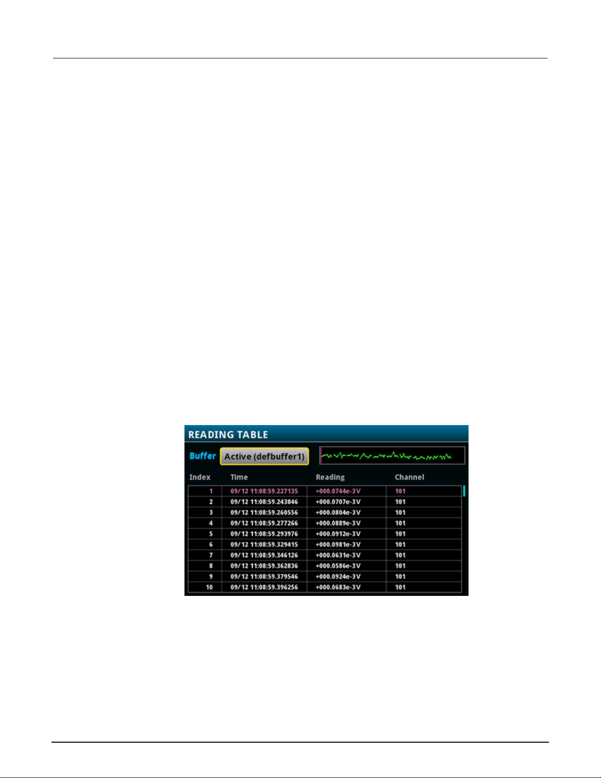
Section
User's Manual
4: Making basic front-panel measurements DAQ6510 Data Acquisition and Multim eter System
If you select a data point, additional detail about t hat data point is displayed, including the function,
math, and limits.
To jump to a specific spot in the data, select the menu in the upper left and select Jump to Index.
The selected data point is displayed at the top of t he reading table.
To save the data, select the menu in the upper left and select Save to USB.
When TERMINALS is set to REAR, you can filter the data using channels and watch channels. The
options include:
• Filter by Watch Channels (Active Buffer): Filters the data by watch c hannels. After selecting
this option, select Edit Watch Channels to select specific channels.
• Edit Watch Channels (Active Buffer): Select which channels are watched channels.
• Filter by Channels: Allows you to limit the data in the readi ng table. After selecting Filter by
Channels, select Edit Channels to specify the channels to display.
• Edit Channels: Allows you to select the channels that are displayed in the reading table.
• No Filtering: Removes filters from the reading table and displays all data for the selected buffer.
Using the front panel to view the contents of a reading buffer:
1. Press the MENU key.
2. Under Views, select Reading Table. Data for the acti ve reading buffer is displayed.
Figure 32: Reading table
3. To display data for a different reading buffer, select the new buffer.
4. To view details for a specific data point, swipe the table up or down and select the data point to
view the Reading Details. If there are many data poin ts, select an area on the reading preview
graph in the upper right corner of the screen to get clo ser to the data you want, and then scroll to
the data point. You can also select the menu and select Jump to Index to go to a specific point.
5. Press the HOME key to return to the home screen.
4-4 DAQ6510-900-01 Rev. B / August 2019
Page 57

Thermocouple temperature scanning ....................................... 5-3
In this section:
Introduction .............................................................................. 5-1
Equipment required .................................................................. 5-1
Device connections .................................................................. 5-1
Introduction
This application example demonstrates how t o use the DAQ6510 to log thermocouple-based
temperature measurement scans, using intern al cold-junction compensation (CJC) correction, over a
24-hour period.
Section 5
Scanning temperature using thermocouples
This type of test is typically performed when a device under test (DUT) is placed in an environmental
chamber and exposed to extreme conditions. The system captures data at different locations on the
DUT. The data is then exported from the DAQ6510 to a computer where a thermal profile is
generated. This thermal profile provides designers and consumers with a thorough understanding of
the thermal operating characteristics of their dev ice or product.
Equipment required
• One DAQ6510
• One Model 7700 20-channel differential mult i plexer module
• One computer set up for communication with the i nstrument
• Ten type K thermocouples
• One USB flash drive
• One device or component to be tested
Device connections
To connect thermocouples to the instrument:
1. Power off the DAQ6510.
2. Remove the 7700 from the DAQ6510.
3. Remove the top cover from the 7700.
Page 58

Section
User's Manual
5: Scanning temperature using therm ocouples DAQ6510 Data Acquisition and Multim eter System
Figure 33: Screw terminal access
4. Connect ten type K thermocouples to each chan nel as shown.
Figure 34: 7700 multiplexer module thermocouple connections
5. Route the cables out through the channels in the 7700 and secure the top cover.
6. Ensure that the DAQ6510 power is turned off.
7. Insert the 7700 into a slot on the rear of the DAQ651 0.
Figure 35: DAQ6510 with 7700 multiplexer module
8. Press the POWER switch on the front panel to turn on the instrument.
9. Set the TERMINALS switch to rear.
10. Plug the USB flash drive into the port on the front of the instrument.
The remaining connections are the thermocouples to the DUT, which typically use soldering, thermal
compound, polyimide tape, or conductive epox y.
5-2 DAQ6510-900-01 Rev. B / August 2019
Page 59

DAQ6510
Scanning temperature using thermocouples
Data Acquisition and Multimeter System User's Manual Section 5:
To prevent electric shock, test connections mu st be configured such that the user cannot
come in contact with test leads or any device u n der test (DUT) that is in contact with the
conductors. It is good practice to disconnect DUTs from the instrument before po wering the
instrument. Safe installation requires proper shields, barriers, and grounding to prevent
contact with test leads.
There is no internal connection between protective earth (safety ground) and the LO
terminals of the DAQ6510. Therefore, hazardous voltages (more than 30 V
LO terminals. This can occur when the instrument is operating in any mode. To prevent
hazardous voltage from appearing on the LO terminals, connect the LO terminal to protectiv e
earth (safety ground) if your application allows it. You can connect the LO terminal to the
chassis ground terminal on the front panel or the chassis ground screw terminal on the rear
panel. Note that the front-panel terminals are isolated from the rear-panel terminals.
Therefore, if you are using the front-panel terminals, ground to the front-panel LO termi nal . I f
you are using the rear-panel terminals, ground to the rear-panel LO terminal. Failure to follow
these guidelines can result in injury, death, or instrument damage.
) can appear on
RMS
Thermocouple temperature scanning
This application demonstrates how to use the DA Q6510 to measure temperature at ten different
points on a DUT every minute over a 24-hour period. During this test, all scan data is automatically
written to a USB flash drive connected to the port on t he inst rument.
For this application, you will:
• Configure the instrument for ten channels of type K thermocouple measurement using internal
cold junction correction (CJC).
• Enable detection of open leads and offset compens ation for more accurate readings.
• Configure the instrument to scan all channels (1 t o 10) once a minute for 24 hours.
• Automatically export the data to a USB flash drive for each completed scan.
• Enable the auto-restart feature to ensure the continuation of progress in the event of power
failure.
• Check the status of the scan progress as it is running.
• Pause the scan and move the data to a computer to begin analysis, prior to scan completion.
• Analyze graphical data of the scan in progress.
• Learn how to program the instrument through the front panel user interface.
• Learn how to program the instrument using a remot e communications interface with SCPI and
TSP code commands.
DAQ6510-900-01 Rev. B / August 2019 5-3
Page 60

Section
User's Manual
5: Scanning temperature using therm ocouples DAQ6510 Data Acquisition and Multimeter System
If you have data on the USB flash drive and want to review it before the scan completes, pause the
scan, remove the drive, copy the data file to y our computer, return the drive to the DAQ6510, and
resume the scan.
Using the front panel
To set up the application from the front panel:
1. Press the POWER switch on the front panel to turn on the instrument.
2. Press the MENU key.
3. Under Channel, select Scan.
4. Select the + button.
5. Add channels 101 to 110. Select OK.
6. Select Temperature on the Measure Functions screen.
7. On the Settings tab, set Thermocouple to K.
8. Scroll down and set the Reference Junction t o Internal.
9. Select the Scan tab.
10. Set the Scan Count to 1440 and select OK. This sets the scan for one scan every minute for 24
hours (24 hours * 60 minutes = 1440).
11. Set the Scan to Scan Interval to 60 s and select OK.
12. Scroll down to Export to a USB flash drive. Select After Each Scan.
13. Set the Filename to scan24hr and select OK.
14. Select OK to accept the remaining File Content sett i ngs.
15. Set Power Loss Restart to On.
16. To start the scan, select Start.
17. Select View Scan Status to go to the SCAN swipe on the home screen.
5-4 DAQ6510-900-01 Rev. B / August 2019
Page 61

DAQ6510
Scanning temperature using thermocouples
*RST
:DISPlay:SCReen SWIPE_SCAN
Data Acquisition and Multimeter System User's Manual Section 5:
Using SCPI commands
This sequence of SCPI commands makes a thermocouple-based temperature scan.
You may need to make changes so that this code will run in your programming environment.
Send the following commands for this example application:
Commands Descriptions
:FUNCtion 'TEMPerature',(@101:110)
:SENSe:TEMPerature:TRANsducer
TCouple, (@101:110)
:SENSe:TEMPerature:TCouple:TYPE K,
(@101:110)
:SENSe:TEMPerature:TCouple:RJUNction:
RSELect INTernal, (@101:110)
:SENSe:TEMPerature:ODETector ON,
(@101:110)
:ROUTe:SCAN:CREate (@101:110)
:ROUTe:SCAN:COUNt:SCAN 1440
:ROUTe:SCAN:INTerval 60.0
:ROUTe:SCAN:EXPORT
"/usb1/scan24hr.csv", SCAN, ALL
:ROUTe:SCAN:RESTart ON
:INIT
Reset the DAQ6510
Set up channel settings for Slot 1
Set up Scan
Set the scan count to 24 hrs * 60 min/hr
= 1440
Set the time between scans to 60 s
Ensure data gets written to a USB drive
after each scan
Enable scan restart after power fai lure
Trigger to start scan
Sends user to the SCAN swipe screen
Using TSP commands
The following TSP code is designed to be run from Keithley Instruments Test Script Builder (TSB).
TSB is a software tool that is available from tek.com/keithley
code and develop scripts for TSP-enabled instruments. Information about how to use TSB is in the
online help for TSB and in the “Introduction to TSP operat i on” section of the Model DAQ6510
Reference Manual.
To use other programming environments, you may need to make changes to the example TSP code.
By default, the DAQ6510 uses the SCPI command set. You must select the TSP command set before
sending TSP commands to the instrument.
To enable TSP commands:
1. Press the MENU key.
2. Under System, select Settings.
3. Set the Command Set to TSP.
4. At the prompt to reboot, select Yes.
. You can install and use TSB to write
DAQ6510-900-01 Rev. B / August 2019 5-5
Page 62

Section
User's Manual
5: Scanning temperature using therm ocouples DAQ6510 Data Acquisition and Multim eter System
This sequence of TSP commands makes a series of t em perature measurements. After the code
executes, the data is displayed in the Instrument Console of Test Script Builder.
Send the following commands for this example application:
-- Reset the instrument to the default settings.
reset()
-- Set up channel settings for slot 1
channel.setdmm("101:110", dmm.ATTR_MEAS_FUNCTION, dmm.FUNC_TEMPERATURE)
channel.setdmm("101:110", dmm.ATTR_MEAS_TRANSDUCER, dmm.TRANS_THERMOCOUPLE)
channel.setdmm("101:110", dmm.ATTR_MEAS_THERMOCOUPLE, dmm.THERMOCOUPLE_K)
channel.setdmm("101:110", dmm.ATTR_MEAS_REF_JUNCTION, dmm.REFJUNCT_INTERNAL)
channel.setdmm("101:110", dmm.ATTR_MEAS_OPEN_DETECTOR, dmm.ON)
-- Set up scan.
scan.create("101:110")
-- Set the scan count to 24hrs * 60min/hr = 1440.
scan.scancount = 1440
-- Set the time between scans to 60 s.
scan.scaninterval = 6.000e+01
-- Ensure data gets written to a connected USB drive after each scan.
scan.export("/usb1/scan24hr.csv", scan.WRITE_AFTER_SCAN, buffer.SAVE_RELATIVE_TIME)
-- Enable scan restart after power failure.
scan.restart = scan.ON
-- Trigger to start the scan.
trigger.model.initiate()
-- Ensure that the display shows the SCAN swipe and carousel.
display.changescreen(display.SCREEN_SCAN_SWIPE)
Test results
The following figures show sample results and final test measurements for this application.
The progress bar in the SCAN swipe screen the chan nel s t hat have been scanned with the
measurement that was made. Only measurement s f or channels selected by Watch Channels are
displayed. Measurements in green are within range. If you have limits set, measurements that are
outside the limits are shown in yellow. Measurements that are shown in red indicate overflow
readings. Red can also indicate that the connecti ons at the screw terminals or DUT are not secure.
Measurements scroll across the swipe screen as they are made. The SCAN swipe screen also
displays the time remaining (in seconds) and the scan countdown.
5-6 DAQ6510-900-01 Rev. B / August 2019
Page 63
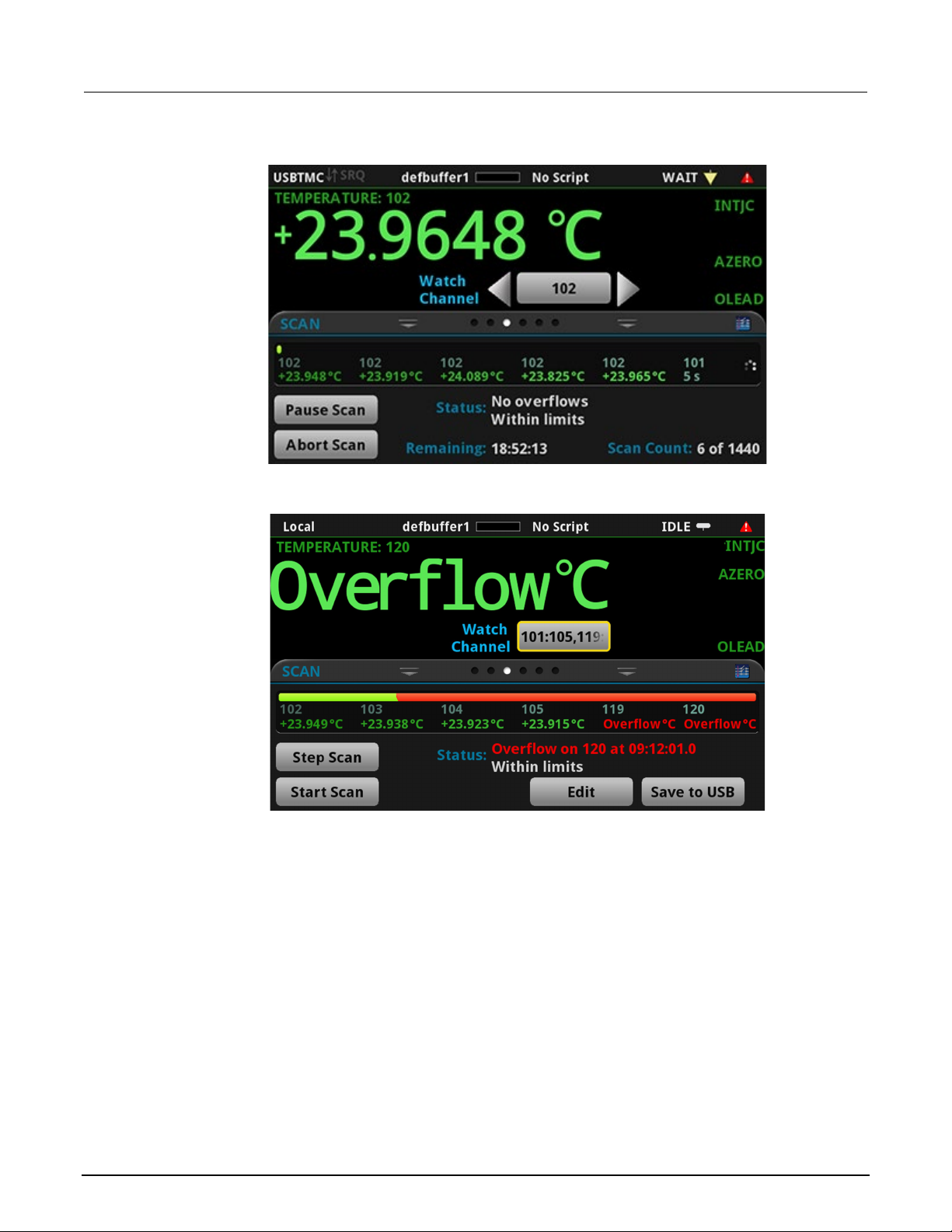
DAQ6510
Scanning temperature using thermocouples
Data Acquisition and Multimeter System User's Manual Section 5:
Figure 36: DAQ6510 scan start screen
Figure 37: Example with overflow measurem en ts
DAQ6510-900-01 Rev. B / August 2019 5-7
Page 64

Section
User's Manual
5: Scanning temperature using therm ocouples DAQ6510 Data Acquisition and Multim eter System
Figure 38: DAQ6510 scanning and temperature graph
5-8 DAQ6510-900-01 Rev. B / August 2019
Page 65

Scanning low-level DCV ........................................................... 6-4
In this section:
Introduction .............................................................................. 6-1
Equipment required .................................................................. 6-1
Device connections .................................................................. 6-2
Introduction
This application example demonstrates how t o use the DAQ6510 to accurately measure DC voltage
in a variety of ranges. To ensure accurate data, the NPLC (Number of Power Line Cycles) and
autozero options are used for this test.
Section 6
Scanning low-level DCV
The NPLC setting can be used to help reduce the induced noise originating from nearby AC
power-conditioning circuits. A desktop powe r supply or power-transmission lines would generate this
type of noise. Increasing NPLC cancels out this noise by integrating all sampled data collected in
multiples of AC signal periods (n * 1/(transmissi on l ine frequency) seconds). The more AC line cycles
used in the measurement, the more accurate the re ading. The time required to conduct the scan also
increases.
The autozero function removes offset voltage s t hat result from thermal EMFs. Thermal EMFs occur
when there is a temperature difference at junctions consisting of different materials. For example,
leads, instrument inputs, or card terminals. T hese EMFs adversely affect DCV measurement
accuracy by offsetting the measured voltage.
This example shows how to measure voltage in different ranges. To optimize scanning speed, you
should set a fixed range. If speed is not an issue, the measurement range can be set to auto.
Equipment required
• One DAQ6510
• One Model 7700 20-channel differential mult i pl exer module
• One computer set up for communication with the i nstrument
• One device or component to be tested
Page 66

Section
User's Manual
6: Scanning low-level DCV DAQ6510 Data Acquisition and Multim eter System
Device connections
This example uses a DAQ6510 with a 7700 multiplexer module. In this example, channels 101 to 106
are connected to six devices under test (DUTs) where DC voltage is measured.
Figure 39: DAQ6510 connections for low-level DCV measurements
To connect devices to the instrument:
1. Power off the DAQ6510.
2. Remove the 7700 from the DAQ6510.
6-2 DAQ6510-900-01 Rev. B / August 2019
Page 67

DAQ6510
level DCV
Data Acquisition and Multimeter System User's Manual Section 6: Scanning low-
3. Remove the top cover from the 7700.
4. Connect six devices.
5. Route the cables out through the cable channels an d secure the top cover.
6. Ensure that the DAQ6510 power is turned off.
7. Insert the 7700 into a slot on the rear of the DAQ651 0.
Figure 40: DAQ6510 with 7700 multiplexer module
8. Press the POWER switch on the front panel to turn on the instrument.
9. Set the TERMINALS switch to REAR.
The remaining connections are to the DUT and are at your discretion.
DAQ6510-900-01 Rev. B / August 2019 6-3
Page 68

Section
User's Manual
6: Scanning low-level DCV DAQ6510 Data Acquisition and Multim eter System
To prevent electric shock, test connections mu st be configured such that the user cannot
come in contact with test leads or any device un d er test (DUT) that is in contact with the
conductors. It is good practice to disconnect DUTs from the instrument before po wering the
instrument. Safe installation requires proper shields, barriers, and grounding to prevent
contact with test leads.
There is no internal connection between protective earth (safety ground) and the LO
terminals of the DAQ6510. Therefore, hazardous voltages (more than 30 V
LO terminals. This can occur when the instrument is operating in any mode. To prevent
hazardous voltage from appearing on the LO terminals, connect the LO terminal to protective
earth (safety ground) if your application allows it. You can connect the LO terminal to the
chassis ground terminal on the front panel or the chassis ground screw terminal on the rear
panel. Note that the front-panel terminals are isolated from the rear-panel terminals.
Therefore, if you are using the front-panel terminals, ground to the front-panel LO termi nal . I f
you are using the rear-panel terminals, ground to the rear-panel LO terminal. Failure to follow
these guidelines can result in injury, death, or instrument damage.
) can appear on
RMS
Scanning low-level DCV
This application demonstrates how to use the DA Q6510 to perform DC voltage measurement using
multiple channels on the 7700 20-channel differential multiplexer module.
For this application, you will:
• Configure channels 101 to 106 for DC voltage measurement.
• Enable autoranging and autozero on each channel.
• Set NPLC to five on each channel.
• Execute 10 scans on all selected channels.
You can program the instrument through the f ront panel or use a remote communications interface
(LAN, USB, GPIB, RS-232, or TSP-Link) using the SCPI or TSP command sets.
6-4 DAQ6510-900-01 Rev. B / August 2019
Page 69

DAQ6510
level DCV
Data Acquisition and Multimeter System User's Manual Section 6: Scanning low-
Using the front panel
To set up the application from the front panel:
1. Press the POWER switch on the front panel to turn on the instrument.
2. Select the REAR terminals.
3. Press the MENU key.
4. Under Channel, select Scan.
5. Select the + button.
6. Select channels 101 to 106 and select OK.
7. Select DC Voltage.
8. On the Settings tab, set NPLC to 5.
9. Set Auto Zero to On.
10. On the Scan tab, set Scan Count to 10.
11. Select Start at the bottom of the left pane.
To watch active readings during scan:
1. Press the HOME key.
2. Select the arrow to the right of Watch Channel.
3. Select the channels and select OK to accept.
To save the scanned measurements to a USB flash drive:
1. Select the MENU key.
2. Under the Measure column, choose Readi ng Buffers.
3. Insert a USB flash drive into the DAQ6510.
4. Select Save to USB at the bottom of the pane.
5. Make settings as needed on the File Content dialog box.
6. Select OK.
Using SCPI commands
This sequence of SCPI commands executes a DCV sc an on channels 101 to 106.
You may need to make changes so that this code will run in your programming environment. In the
table, the SCPI commands have a light gray backgr ound. The light green shaded code represents
pseudocode that will vary depending on the progr am ming environments you use.
DAQ6510-900-01 Rev. B / August 2019 6-5
Page 70

Section
User's Manual
Pseudocode
int scanCount = 10
every two seconds
DAQ6510
*RST
Initiate the scan
Pseudocode
for i = 1; i <= bufferSize;
accumulate
DAQ6510
lastIndex = TRACe:ACTual?
READ
Pseudocode
printBuffer (tmpBuffer)
DAQ6510
:TRAC:SAVE "/usb1/MyData.csv",
"defbuffer1"
6: Scanning low-level DCV DAQ6510 Data Acquisition and Multim eter System
Send the following commands for this example application:
Commands Descriptions
int channelCount = 6
int bufferSize = scanCount *
channelCount
int lastIndex
string tmpBuff
Create a variable to hold the scan count
Create a variable to hold channel count
The number of readings
The last scan index in the buffer aft er every
two seconds
A temporary buffer that store scanned data
:TRAC:POIN bufferSize,
"defbuffer1"
:ROUT:SCAN:BUFF "defbuffer1"
FUNC 'VOLT:DC', (@101:106)
VOLT:DC:RANG:AUTO ON,
(@101:106)
VOLT:DC:NPLC 5, (@101:106)
VOLT:DC:AZER ON, (@101:106)
ROUT:SCAN (@101:106)
ROUT:SCAN:COUN:SCAN 10
INIT
Put the instrument in a known state
Set the buffer size (not necessary when using
the default buffer, but added to sho w
command use case)
Assign all scanned data to "defbuffer 1"
Set channels functions to DCV
Set the channels ranges to auto
Set NPLC to 5
Set autozero function to ON
Setup the scan list
Setup the number of repeated scans
delay 2000
tmpBuff = "TRACe:DATA? i,
lastIndex, "defbuffer1",
Delay two seconds to allow readings t o
Query the current buffer index
Query the readings available from i ndex i to
index lastIndex
Print readings in temporary buffer to console
i = lastIndex + 1
end for
Save buffer data from defbuffer1 to U S B
6-6 DAQ6510-900-01 Rev. B / August 2019
Page 71

DAQ6510
level DCV
Data Acquisition and Multimeter System User's Manual Section 6: Scanning low-
Using TSP commands
The following TSP code is designed to be run from Keithley Instruments Test Script Builder (TSB).
TSB is a software tool that is available from tek.com/keithley
code and develop scripts for TSP-enabled instruments. Information about how to use TSB is in the
online help for TSB and in the “Introduction to TSP operat i on” section of the Model DAQ6510
Reference Manual.
To use other programming environments, you may need to make changes to the example TSP code.
By default, the DAQ6510 uses the SCPI command set. You must select the TSP command set before
sending TSP commands to the instrument.
To enable TSP commands:
1. Press the MENU key.
2. Under System, select Settings.
3. Set the Command Set to TSP.
4. At the prompt to reboot, select Yes.
. You can install and use TSB to write
This sequence of TSP commands initiates a seri es of temperature measurements. After the code
executes, the data is displayed in the Instrument Console of Test Script Builder.
Send the following commands for this example application:
-- Reset the instrument to the default settings
reset()
channelCount = 6
scanCount = 10
bufferSize = channelCount * scanCount
defbuffer1.capacity = bufferSize
scan.buffer = defbuffer1 -- not necessary when using the default buffer, but added to
show command use case.
-- set up channels
channel.setdmm("101:106", dmm.ATTR_MEAS_FUNCTION, dmm.FUNC_DC_VOLTAGE,
dmm.ATTR_MEAS_RANGE_AUTO, dmm.ON, dmm.ATTR_MEAS_AUTO_ZERO, dmm.ON,
dmm.ATTR_MEAS_NPLC, 5)
-- set up Scan
scan.add("101:106")
scan.scancount = scanCount
-- set up trigger model
trigger.model.initiate()
-- print measurement data to console
i = 1
while i <= bufferSize do
delay(2)
lastIndex = defbuffer1.n
printbuffer(i, lastIndex, defbuffer1.readings)
i = lastIndex + 1
end
-- save buffer data from defbuffer1 to USB
buffer.save(defbuffer1, "/usb1/MyData.csv")
DAQ6510-900-01 Rev. B / August 2019 6-7
Page 72

Scanning resistors using 4-wir e measurements ....................... 7-4
In this section:
Introduction .............................................................................. 7-1
Equipment required .................................................................. 7-2
Device connections .................................................................. 7-2
Introduction
This example application demonstrates how to use the DAQ6510 to accurately measure resistance
across multiple devices. To obtain the best result s, the 4-wire (Kelvin) measurement method and
offset compensation are used for this test.
Section 7
Scanning resistors using 4W measurement
Typical resistance measurements made using t he 2-wire method source current through the test
leads and the device under test (DUT). The voltage is measured, and the resistance is calculated.
It is difficult to get accurate 2-wire resistance measurements when the DUT is less than 100 Ω.
Typical lead resistances are in the range of 10 mΩ to 100 mΩ. All of the leads in the example in this
chapter are 250 mΩ to 500 mΩ. When the 2-wire method is applied to low-resista nce measurements,
there is a small but significant voltage drop acro ss the resistance of each test lead. The voltage
measured by the instrument is not the same as the vol tage directly across the DUT.
The 4-wire method is preferred for low-resistance measurements. With this configuration, the test
current is sourced through the DUT using one set of test leads, while a second set of SENSE leads
measures the voltage across the DUT. The voltage-sensing leads are connected as close to the
device under test as possible to avoid including the resistance of the test leads in the measurement.
Thermoelectric voltages (EMFs) can seriously affect low-resistance measurement accuracy. The
DAQ6510 can apply the offset-compensated ohms method (OCOMP), which makes one normal
resistance measurement and one using the lowest cu rrent source setting to eliminate EMFs.
For this example, you will use resistors of di f ferent low values across multiple channels of a 7700
multiplexer module and examine how the 4-wire measurement method provides a more accurate
reading than the 2-wire method. Fixed measurement ranges are applied in order to optimize scanning
speed and OCOMP is applied to correct for any EMF effects.
Page 73

Section
User's Manual
7: Scanning resistors using 4W mea s urement DAQ6510 Data Acquisition and Multim eter System
For comprehensive information on 4-wire re sistance measurements, thermoelectric EMFs, and off set
compensation methods, see the Low Level Measurements Handbook, available on tek.com/keithley
Equipment required
• One DAQ6510
• One Model 7700 20-channel differential multiplexer module
• One computer set up for communication with the instrument
• Six resistors of 100 Ω, 68 Ω, 10 Ω, 2.2 Ω, 0.5 Ω, and 0.2 Ω
• One device or component to be tested
Device connections
This example application uses the DAQ6510 to perf orm a 4-wire measurement using multiple
channels on a 7700 multiplexer module.
.
For this example you will:
• Configure channels 101, 102, 103, 104, 105, and 106 to measure resistors (in this case, 100 Ω,
68 Ω, 10 Ω, 2.2 Ω, 0.5 Ω, and 0.2 Ω).
• Pair channels 111 to 116 with channels 101 to 106, respectively, to provide the SENSE
connections needed for 4-wire measurements.
• Select fixed ranges and apply offset compensation to each channel.
• Execute 100 scans for all selected channels.
7-2 DAQ6510-900-01 Rev. B / August 2019
Page 74

DAQ6510
Scanning resistors using 4W mea surement
Data Acquisition and Multimeter System User's Manual Section 7:
Figure 41: Schematic of 4W measurement
To highlight the impact of test lead resistance on low-resistance measurements, and how the
correction methods improve readings, the con nections to each DUT consist of one meter of 22 AWG
wire.
To prevent electric shock, test connections must be configured such that the user cannot
come in contact with test leads or any device un d er test (DUT) that is in contact with the
conductors. It is good practice to disconnect power before connecting DUTs. Safe installation
requires proper shields, barriers, and grounding to prevent contact with test leads.
DAQ6510-900-01 Rev. B / August 2019 7-3
Page 75

Section
User's Manual
7: Scanning resistors using 4W mea s urement DAQ6510 Data Acquisition and Multim eter System
There is no internal connection between protective earth (safety ground) and the LO
terminals of the DAQ6510. Therefore, hazardous voltages (more than 30 V
LO terminals. This can occur when the instrument is operating in any mode. To prevent
hazardous voltage from appearing on the LO terminals, connect the LO terminal to protectiv e
earth (safety ground) if your application allows it. You can connect the LO terminal to the
chassis ground terminal on the front panel or the chassis ground screw terminal on the rear
panel. Note that the front-panel terminals are isolated from the rear-panel terminals.
Therefore, if you are using the front-panel terminals, ground to the front-panel LO terminal. If
using the rear-panel terminals, ground to the rear panel LO terminal. Failure to follow these
guidelines can result in injury, death, or instrument damage.
Scanning resistors using 4-wire measurements
Using the front panel
To setup the application from the front panel:
) can appear on
RMS
1. Press the POWER switch on the front panel to turn on the instrument.
2. Set the TERMINALS switch to REAR.
3. Press the MENU key.
4. Under Channel, select Scan.
5. Select the + button.
6. Select channels 101 to 106 and select OK.
7. Select 4W Resistance on the Measure Functions screen.
8. In the Settings tab, set Offset Compensation to On.
9. In the upper left corner of the screen, select the Menu icon and select Expand Group. Each
channel is now displayed individually.
10. For channel 101, select 4 Wire Res.
11. Under the Settings tab, select Range and set to 100 Ω.
12. For channel 102, select 4-Wire Res and set the Range to 100 Ω.
13. For channel 103, select 4-Wire Res and set the Range to 10 Ω.
14. For channel 104, select 4-Wire Res and set the Range to 10 Ω.
15. For channel 105, select 4-Wire Res and set the Range to 1 Ω.
16. For channel 106, select 4-Wire Res and set the Range to 1 Ω.
17. Select the Scan tab.
18. Set the Scan Count to 100.
19. Select the Start button at the bottom of the left-side pane to start the scan.
7-4 DAQ6510-900-01 Rev. B / August 2019
Page 76

DAQ6510
Scanning resistors using 4W mea surement
*RST
Wait for scan completion
Data Acquisition and Multimeter System User's Manual Section 7:
You can monitor active readings during the scan or review all scanned data after the scan finishes.
To watch readings during scan:
1. Press the HOME key.
2. Select Watch Channel.
3. Select the channels to watch.
4. Select OK to accept. The readings are displayed in the SCAN swipe screen.
To review the data when the scan finishes:
1. Press the MENU key.
2. Under the Views column, choose Reading Table.
Using SCPI commands
This sequence of SCPI commands executes a 4-wir e resistance scan.
You may need to make changes so that this code will run in your programming environment.
Send the following commands for this example applicati o n:
Commands Descriptions
ROUT:SCAN:COUN:SCAN 100
FUNC 'FRES',(@101:106)
FRES:OCOM ON, (@101:106)
FRES:RANG 100, (@101,102)
FRES:RANG 10, (@103,104)
FRES:RANG 1, (@105,106)
ROUT:SCAN:CRE (@101:106)
TRAC:CLE
INIT
*WAI
Reset the DAQ6510
Set the number of times the scan is repeated
to 100
Set function to 4-wire measurement
Set offset compensation to on
Set the fixed range for channels 101 a nd 102
to 100 Ω
Set the fixed range for channels 103 a nd 104
to 10 Ω
Set the fixed range for channels 105 a nd 106
to 1 Ω
Create the scan list
Clear the reading buffer
Initiate the scan
Using TSP commands
DAQ6510-900-01 Rev. B / August 2019 7-5
The following TSP code is designed to be run from Keithley Instruments Test Script Builder (TSB).
TSB is a software tool that is available from tek.com/keithley
code and develop scripts for TSP-enabled instruments. Information about how to use TSB is in the
online help for TSB and in the “Introduction to TSP operat ion” section of the Model DAQ6510
Reference Manual.
. You can install and use TSB to write
Page 77

Section
User's Manual
100
98.3242
98.3206
98.5831
68
67.9920
68.0080
67.2703
10
10.00998
10.00141
10.28680
2.2
2.20413
2.20588
2.51011
0.5
0.555823
0.559395
0.84131
0.2
0.221831
0.221796
0.53091
7: Scanning resistors using 4W mea s urement DAQ6510 Data Acquisition and Multim eter System
To use other programming environments, you may need to make changes to the example TSP code.
By default, the DAQ6510 uses the SCPI command set. You must select the TSP command set before
sending TSP commands to the instrument.
To enable TSP commands:
1. Press the MENU key.
2. Under System, select Settings.
3. Set the Command Set to TSP.
4. At the prompt to reboot, select Yes.
This sequence of TSP commands initiates a series of temperature measurements. After the code
executes, the data is displayed in the Instrument Console of Test Script Builder.
After the scan, the data in the buffer is stored on a USB flash drive.
Send the following commands for this example application:
-- Reset the instrument to the default settings.
reset()
scanCount = 100
-- Set up the function, range and offset compensation for the channels.
channel.setdmm("101, 102", dmm.ATTR_MEAS_FUNCTION, dmm.FUNC_4W_RESISTANCE,
dmm.ATTR_MEAS_RANGE, 100, dmm.ATTR_MEAS_OFFCOMP_ENABLE, dmm.OCOMP_ON)
channel.setdmm("103, 104", dmm.ATTR_MEAS_FUNCTION, dmm.FUNC_4W_RESISTANCE,
dmm.ATTR_MEAS_RANGE, 10, dmm.ATTR_MEAS_OFFCOMP_ENABLE, dmm.OCOMP_ON)
channel.setdmm("105, 106", dmm.ATTR_MEAS_FUNCTION, dmm.FUNC_4W_RESISTANCE,
dmm.ATTR_MEAS_RANGE, 1, dmm.ATTR_MEAS_OFFCOMP_ENABLE, dmm.OCOMP_ON)
-- Set up the scan.
scan.add("101,102,103,104,105,106")
scan.scancount = 100
-- Set up the trigger model.
trigger.model.initiate()
-- Wait until scan completes.
waitcomplete()
Test results
The table below compares the values of scanne d DUTs using 4-wire and 2-wire measurement
methods with the six resistors. The data provided in each cell of the table is the average of 100
scans.
Nominal
value (Ω)
7-6 DAQ6510-900-01 Rev. B / August 2019
Four-wire measurement
with offset compensation
(Ω)
Four-wire measurement
with NO offset
compensation (Ω)
Two-wire measurement
(Ω)
Page 78

Mixed function multi-channel s canning .................................... 8-4
In this section:
Introduction .............................................................................. 8-1
Equipment required .................................................................. 8-2
Device connections .................................................................. 8-2
Introduction
This example application demonstrates how to use the DAQ6510 to perform complex multi-channel,
mixed function scanning in a production test environment.
Section 8
Mixed function multi-channel scanning
The DAQ6510 can perform more than one function in a multichannel scan, providing a range of
data-acquisition options in a single test.
In this production environment, the DAQ6510 is:
• Integrated into a test stand.
• Wired to a fixture that is connected to an active device under test (DUT).
• Quickly capturing DC volts and current; temperature; and AC volts and current.
Before the start of the scan, you can step through e ach of the configured channels on the DAQ6510,
which allows you to troubleshoot the test configuration. This allows you to view the readings of
individually closed channels to ensure that conn ect ions to the DUT are secure.
For this application, you:
• Configure the instrument for:
One channel each of ACV, ACI, and DCI.
Nine channels of DCV.
Four channels of temperature using type K thermocouple s using a simulated reference
junction.
• Set labels on certain channels to help identify what the measurement is monitoring at the DUT.
• Step through the scan to check each individual channel reading before scanning.
• Execute 10 scans for each selected channel.
• Use the reading table to view (or print) the scanned m easurements.
Page 79

Section
User's Manual
8: Mixed function multi-channel scanning DAQ6510 Data Acquisition and Multim eter System
You can operate the instrument through t he f ront panel or using SCPI or TSP code. For information
about setting up remote communications, see Rem ote communications interfaces (on page 3-1
Equipment required
• One DAQ6510
• One Model 7700 20-channel differential mult i pl exer module
• One computer set up for communication with the i nstrument
).
• One device or component to be tested
Device connections
This application example uses a DAQ6510 with a 77 00, 20-channel differential multiplexer configure d
to monitor the following signals:
• Channel 101: AC voltage being supplied to t he DUT.
• Channels 102 to 110: DC voltages at several points locat ed on the DUT.
• Channels 111 to 112: Temperature (using type K t hermocouples) of two voltage regulators within
the DUT.
• Channels 113 to 114: Temperature (using type K t hermocouples) of two loads to which the DUT
is supplying power.
• Channel 121: AC current being drawn by the DUT.
• Channel 122: DC current being drawn by the load.
8-2 DAQ6510-900-01 Rev. B / August 2019
Page 80
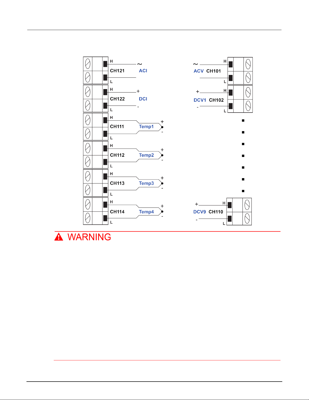
DAQ6510
channel scanning
Data Acquisition and Multimeter System User's Manual Section 8: Mixed function multi-
Figure 42: 7700 channel connections
To prevent electric shock, test connections mu st be configured such that the user cannot
come in contact with test leads or any device un d er test (DUT) that is in contact with the
conductors. It is good practice to disconnect DUTs from the instrument before po wering the
instrument. Safe installation requires proper shields, barriers, and grounding to prevent
contact with test leads.
There is no internal connection between protective earth (safety ground) and the LO
terminals of the DAQ6510. Therefore, hazardous v oltages (more than 30 V
) can appear on
RMS
LO terminals. This can occur when the instrument is operating in any mode. To prevent
hazardous voltage from appearing on the LO terminals, connect the LO terminal to protectiv e
earth (safety ground) if your application allows it. You can connect the LO terminal to the
chassis ground terminal on the front panel or the chassis ground screw terminal on the rear
panel. Note that the front-panel terminals are isolated from the rear-panel terminals.
Therefore, if you are using the front-panel terminals, ground to the front-panel LO termi nal . I f
you are using the rear-panel terminals, ground to the rear-panel LO terminal. Failure to follow
these guidelines can result in injury, death, or instrument damage.
DAQ6510-900-01 Rev. B / August 2019 8-3
Page 81

Section
User's Manual
8: Mixed function multi-channel scanning DAQ6510 Data Acquisition and Multimeter System
Mixed function multi-channel scanning
The following topics describe how to set up mult i-channel scanning from the front panel, using SCPI
commands, and using TSP commands.
Using the front panel
To set up the application from the front panel:
1. Press the POWER switch on the front panel to turn on the instrument.
2. Set the TERMINALS switch to REAR.
3. Swipe to the SCAN swipe screen.
4. Select Build Scan.
5. Select the + button.
6. Select channel 101 and select OK.
7. Select AC Voltage on the Measure Functions screen.
8. In the Settings tab, set the Detector Bandwidth to 30 Hz.
9. Scroll to Label (at the bottom of the Settings tab) and set the label to ACMains.
10. Select the + button.
11. Select channels 102 to 110 and select OK.
12. Select DC Voltage.
13. Select the + button.
14. Select channels 111 to 114 and select OK.
15. Select Temperature.
16. On the Settings tab, set Temperature to a simulated junction temperature of 23 °C.
17. Set the Reference Junction to Simulated.
18. In the top left corner of the screen, select Menu and select Expand Groups.
19. Select channel 111 and enter Reg12VTemp for the label. Select OK.
20. Select channel 112 and enter Reg5VTemp for the label. Select OK.
21. Select channel 113 and enter LoadTemp1 for the label. Select OK.
22. Select channel 114 and enter LoadTemp2 for the label. Select OK.
23. Select the Menu and select Collapse Groups. The AC Volt, DC Volt, and Temp channels are
separated into individual groups.
24. Select the + button.
25. Add channel 121 and select OK.
26. Select AC Current.
27. Select the + button.
28. Add channel 122 and select OK.
8-4 DAQ6510-900-01 Rev. B / August 2019
Page 82

DAQ6510
channel scanning
*RST
SENS:TEMP:TC:RJUN:SIM 23, (@111:114)
Query the readings from the instrument
Data Acquisition and Multimeter System User's Manual Section 8: Mixed function multi-
29. Select DC Current.
30. On the Scan tab, set the Scan Count to 10.
31. Press the HOME key.
32. To validate each channel, select Step Scan. This closes the first channel in the scan and
displays the results. Use the arrows next to Wat ch C hannel to scroll through the selected
channels, selecting Step Scan on each, until all t he channels have been validated.
33. Select Abort Scan.
34. Press the TRIGGER key to the right of the display to initiate the scan.
Using SCPI command s
This sequence of SCPI commands configures the instrument for measuring DC Voltage, Temperature,
AC Voltage, DC Current, and AC Current on different channels and then labels some of those
channels. Each channel is then scanned 10 times and the readings are returned.
You may need to make changes so that this code will run in your programming environment. In the
table, the SCPI commands have a light gray backgr ound.
Send the following commands for this example application:
Commands Descriptions
SENS:FUNC 'VOLT:AC',(@101)
SENS:VOLT:AC:DET:BAND 30, (@101)
SENS:FUNC 'VOLT:DC', (@102:110)
SENS:FUNCtion 'TEMPerature',
(@111:114)
SENS:TEMP:TRAN TC, (@111:114)
SENS:TEMP:TC:TYPE K, (@111:114)
SENS:TEMP:TC:RJUN:RSEL SIM,
(@111:114)
SENS:FUNC 'CURR:AC', (@121)
SENS:FUNC 'CURR:DC', (@122)
ROUT:CHAN:LAB "ACMains", (@101)
ROUT:CHAN:LAB "Reg12VTemp", (@111)
ROUT:CHAN:LAB "Reg5VTemp", (@112)
ROUT:CHAN:LAB "LoadTemp1", (@113)
ROUT:CHAN:LAB "LoadTemp2", (@114)
ROUTe:SCAN:COUNt:SCAN 10
ROUTe:SCAN:CREate (@101:114,121,122)
INIT
*WAI
TRAC:DATA? 1, 160, "defbuffer1",
READ, CHAN
Reset the instrument
Set channel 101 for ACV
Set channel 101, low-end bandwidth to
30Hz
Set channels 102 to 110 for DCV
Set channels 111 to 114 for temperatur e
measurement using type K
thermocouples with a simulated ref er ence
junction set to 23°C
Set channel 121 to measure ACI
Set channel 122 to measure DCI
Apply a label to channel 101
Apply a label to channel 111
Apply a label to channel 112
Apply a label to channel 113
Apply a label to channel 114
Set the number of scans
Create a list of channels to includ e i n the
scan
Initiate the scan
Wait for scan completion
DAQ6510-900-01 Rev. B / August 2019 8-5
Page 83

Section
User's Manual
8: Mixed function multi-channel scanning DAQ6510 Data Acquisition and Multim eter System
Using TSP commands
The following TSP code is designed to be run from Keithley Instruments Test Script Builder (TSB).
TSB is a software tool that is available from tek.com/keithley
code and develop scripts for TSP-enabled instruments. Information about how to use TSB is in the
online help for TSB and in the “Introduction to TSP operat i on” section of the Model DAQ6510
Reference Manual.
To use other programming environments, you may need to make changes to the example TSP code.
By default, the DAQ6510 uses the SCPI command set. You must select the TSP command set before
sending TSP commands to the instrument.
To enable TSP commands:
1. Press the MENU key.
2. Under System, select Settings.
3. Set the Command Set to TSP.
4. At the prompt to reboot, select Yes.
. You can install and use TSB to write
This sequence of TSP commands makes a series of t em perature measurements. After the code
executes, the data is displayed in the Instrument Console of Test Script Builder.
Send the following commands for this example application:
-- Reset the instrument to the default settings.
reset()
-- Establish channel settings for the scan card configuration.
channel.setdmm("101", dmm.ATTR_MEAS_FUNCTION, dmm.FUNC_AC_VOLTAGE)
channel.setdmm("101", dmm.ATTR_MEAS_DETECTBW, dmm.DETECTBW_30HZ)
channel.setdmm("102:110", dmm.ATTR_MEAS_FUNCTION, dmm.FUNC_DC_VOLTAGE)
channel.setdmm("111:114", dmm.ATTR_MEAS_FUNCTION, dmm.FUNC_TEMPERATURE)
channel.setdmm("111:114", dmm.ATTR_MEAS_TRANSDUCER, dmm.TRANS_THERMOCOUPLE)
channel.setdmm("111:114", dmm.ATTR_MEAS_THERMOCOUPLE, dmm.THERMOCOUPLE_K)
channel.setdmm("111:114", dmm.ATTR_MEAS_REF_JUNCTION, dmm.REFJUNCT_SIMULATED)
channel.setdmm("111:114", dmm.ATTR_MEAS_FUNCTION, dmm.FUNC_TEMPERATURE,
dmm.ATTR_MEAS_SIM_REF_TEMP, 23)
channel.setlabel("101", "ACMains")
channel.setlabel("111", "Reg12VTemp")
channel.setlabel("112", "Reg5VTemp")
channel.setlabel("113", "LoadTemp1")
channel.setlabel("114", "LoadTemp2")
channel.setdmm("121", dmm.ATTR_MEAS_FUNCTION, dmm.FUNC_AC_CURRENT)
channel.setdmm("122", dmm.ATTR_MEAS_FUNCTION, dmm.FUNC_DC_CURRENT)
-- Generate the scan.
scan.create("101:114,121,122")
scan.scancount = 10
-- Clear and size the buffer.
defbuffer1.clear()
defbuffer1.capacity = 10 * 16
8-6 DAQ6510-900-01 Rev. B / August 2019
Page 84

DAQ6510
channel scanning
Data Acquisition and Multimeter System User's Manual Section 8: Mixed function multi-
-- Start the scan and wait.
trigger.model.initiate()
waitcomplete()
-- Extract the data.
printbuffer(1, defbuffer1.n, defbuffer1, defbuffer1.readings, defbuffer1.channels)
Test results
To display the results for this application:
1. Press the Menu key.
2. Under Views, select Reading Table.
3. Scroll the reading table noting both the measurements and labels in the Channel column of the
table.
Figure 43: DAQ6510 reading table mixed function multichannel scanning
To save the scanned measurements to a USB flash drive:
1. Select the MENU key.
2. Under the Measure column, choose Readi ng Buffers.
3. Insert a USB flash drive into the DAQ6510.
4. Select Save to USB.
5. Set the Filename to MixedScan.
6. Select OK.
DAQ6510-900-01 Rev. B / August 2019 8-7
Page 85

Speed scanning for increased product ion test throughput ....... 9-3
In this section:
Introduction .............................................................................. 9-1
Equipment required .................................................................. 9-2
Device connections .................................................................. 9-2
Introduction
There are three different multiplex modules avail able for use with the DAQ6510. This application
example demonstrates how each of the mult ipl exer modules can impact productivity by changing test
time. The multiplexer modules all share the sam e basic code base for switching, scanning, and
measuring. Any limits on system speed are the res ult of the relays in the multiplexer that switch the
signals from the device under test (DUT) into the inst rument.
Section 9
Speed scanning for increased test throughput
The Model 7700 20-Channel Differential Mult i plexer Module uses electromechanical relays which
have low contact resistance and contribute only a minor offset potential (<1 Ω through the end of life
and < 500 nV, respectively). This results in t he m ost accurate readings of the modules but with a
3 ms relay closure time, the slowest scan time i n comparison to other options.
The 7703 multiplexer module uses reed relays which have low contact resistance (<1 Ω through the
end of life), but a higher contact potential (6 µV max) which contributes more signal offset and slightly
less precise readings. The benefit of this module is short er relay close time (less than 1 ms) which
makes it approximately three times faster than the 7700.
The 7710 multiplexer module uses solid-state relays which have the highest contact resistance and
contact potential of the three options (<5 Ω and <1 µV, respectively) and are therefore the least
precise, however the 7710 has the overall spe ed advantage with a relay close time of less than
0.5 ms, making it twice as fast as the 7703 and at least six times faster than the 7700.
For comprehensive information on relay types, topologies, and the benefits or drawbacks of each, go
to the Keithley webpage on the tek.com/keithley
and search for the Switching Handbook.
Page 86

Section
User's Manual
9: Speed scanning for increased t est throughput DAQ6510 Data Acquisition and Multim eter System
Equipment required
• One DAQ6510
• One Model 7700 20-channel differential mult i pl exer module
• One Model 7710 20-channel differential mult i pl exer module
• One computer set up for remote communicatio n with the DAQ6510
• One device or component to be tested
Device connections
This example assumes a setup optimized for the gre atest speed where the DAQ6510 uses either the
7700 or 7710 20-channel differential multiplexer module multiple to monitor the following signals; t he
example code is the same for each.
The controlling computer can use either LAN, US B, or GPIB to reach scan and data transfer speeds
comparable to those of the original factory setup. The GPIB interface requires an optional
communications accessory.
See the following image for the connection ex am ple.
Figure 44: DAQ6510 speed scanning instrumen t and device connection
9-2 DAQ6510-900-01 Rev. B / August 2019
Page 87

DAQ6510
hroughput
Data Acquisition and Multimeter System User's Manual Section 9: Speed scanning for increased test t
The 7700 replaces the 7710 for the second run of the program code for comparison and assumes
the same input signals to channels 101 to 120.
To prevent electric shock, test connections mu st be configured such that the user cannot
come in contact with test leads or any device un d er test (DUT) that is in contact with the
conductors. It is good practice to disconnect DUTs from the instrument before po wering the
instrument. Safe installation requires proper shields, barriers, and grounding to prevent
contact with test leads.
There is no internal connection between protective earth (safety ground) and the LO
terminals of the DAQ6510. Therefore, hazardous v oltages (more than 30 V
) can appear on
RMS
LO terminals. This can occur when the instrument is operating in any mode. To prevent
hazardous voltage from appearing on the LO terminals, connect the LO terminal to protectiv e
earth (safety ground) if your application allows it. You can connect the LO terminal to the
chassis ground terminal on the front panel or the chassis ground screw terminal on the rear
panel. Note that the front-panel terminals are isolated from the rear-panel terminals.
Therefore, if you are using the front-panel terminals, ground to the front-panel LO termi nal . I f
you are using the rear-panel terminals, ground to the rear-panel LO terminal. Failure to follow
these guidelines can result in injury, death, or instrument damage.
Speed scanning for increased production test throughput
This application demonstrates how to configure the DAQ6510 to execute scans at the best scan
speed. You will eliminate certain measurement opti ons that add to overall test time. The scan
completion times of the 7700 and 7710 20-chann el differential multiplexer modules will be compared,
and you will see the speed improvement attributed to solid-state relays over electromechanical relays
used in some multiplexer modules.
DAQ6510-900-01 Rev. B / August 2019 9-3
Page 88

Section
User's Manual
Pseudocode
int scanCnt = 1000
elapsed time
9: Speed scanning for increased t est throughput DAQ6510 Data Acquisition and Mult imeter System
For this application, you:
• Use the sample code (either SCPI or TSP) to issu e commands that:
Fix the DCV measurement range for all channels and remove the delay time introduced
through autoranging.
Eliminate the autozero feature to remove extra correct i on m easurements from being
performed.
Set the display digits to a low resolution and turn off the front panel to bypass any delays that
would come from updates/refreshes.
Turn off channel statistics calculation so that the instr ument puts its processing power into
data acquisition and transmission.
Disable line synchronization.
Execute a 20-channel scan with a count of 1000 for a total sample count of 20,000 readings.
Incrementally extract the most current scan measurem ent s unt i l complete and either save
them to a file or print them to the computer display.
Using SCPI commands
• Evaluate the elapsed time.
This sequence of SCPI commands executes a 20-c hannel scan 1000 times and saves the data to the
controlling computer.
You may need to make changes so that this code will run in your programming environment. In the
table, the SCPI commands have a light gray backgr ound. The light green shaded code represents
pseudocode that will vary depending on the progr am ming environments you use.
Send the following SCPI commands for this example application:
Commands Descriptions
int sampleCnt
int chanCnt
int actualRdgs
string rcvBuffer
timer1.start()
Create a variable to hold the scan
count
Create a variable to hold the full
sample count (total number of
readings)
Create a variable to hold the
channel count
Create a variable to hold the actual
reading count
Create a string buffer to hold
extracted readings
Start a timer to help capture
9-4 DAQ6510-900-01 Rev. B / August 2019
Page 89

DAQ6510
Speed scanning for increased t est throughput
DAQ6510
*RST
Query the channel count
Pseudocode
sampleCnt = scanCnt * chanCnt
taken
INIT
Initiate the scan
Pseudocode
for i = 1, i < sampleCnt
to accumulate
DAQ6510
actualRdgs = TRACe:ACTual?
READ
Pseudocode
WriteReadings("C:\myData.csv"
Calculate the elapsed time
DAQ6510
DISP:LIGH:STAT ON100
Turn the display on
Data Acquisition and Multimeter System User's Manual Section 9:
FORM:DATA ASCII
ROUT:SCAN:COUN:SCAN 1000
FUNC 'VOLT:DC',(@101:120)
VOLT:RANG 1, (@101:120)
VOLT:AVER:STAT OFF, (@101:120)
DISP:VOLT:DIG 4, (@101:120)
VOLT:NPLC 0.0005, (@101:120)
VOLT:LINE:SYNC OFF, (@101:120)
VOLT:AZER:STAT OFF, (@101:120)
CALC2:VOLT:LIM1:STAT OFF,
(@101:120)
CALC2:VOLT:LIM2:STAT OFF,
(@101:120)
ROUT:SCAN:INT 0
TRAC:CLE
DISP:LIGH:STAT OFF
ROUT:SCAN:CRE (@101:120)
chanCnt =
ROUTe:SCAN:COUNt:STEP?
Format data as an ASCII string
Apply the scan count
Set function to DCV
Set the fixed range at 1 V
Disable background statistics
Front panel shows only four
Set fastest NPLC possible
Turn off line sync
Turn off auto zero
Turn off limit tests
Set trigger interval between scans
Clear the reading buffer
Put the instrument in a known stat e
significant digits
to 0s
Turn the display off
Set the scan list
Calculate the number of readings
DAQ6510
delay 500
Setup a loop from one up to
sampleCnt, but leave the
incrementing of i for later
Delay for 500 ms to allow readings
rcvBuffer = "TRACe:DATA? i,
actualRdgs, "defbuffer1",
, rcvBuffer)
i = actualRdgs + 1
end for
timer1.stop()
timer1.stop – timer1.start
Query the actual readings captured
Query the readings available from i
to the value of actualRdgs
Write the extracted readings to a
file, myData.csv, on the local
computer
Increment i for the next loop pass
End the for loop
Stop the timer
DAQ6510-900-01 Rev. B / August 2019 9-5
Page 90

Section
User's Manual
9: Speed scanning for increased t est throughput DAQ6510 Data Acquisition and Mult imeter System
Using TSP commands
The following TSP code is designed to be run from Keithley Instruments Test Script Builder (TSB).
TSB is a software tool that is available from tek.com/keithley
code and develop scripts for TSP-enabled instruments. Information about how to use TSB is in the
online help for TSB and in the “Introduction to TSP operat i on” section of the Model DAQ6510
Reference Manual.
To use other programming environments, you may need to make changes to the example TSP code.
By default, the DAQ6510 uses the SCPI command set. You must select the TSP command set before
sending TSP commands to the instrument.
To enable TSP commands:
1. Press the MENU key.
2. Under System, select Settings.
3. Set the Command Set to TSP.
4. At the prompt to reboot, select Yes.
. You can install and use TSB to write
This sequence of TSP commands makes a series of voltage measurements. After the code executes,
the data is displayed in the Instrument Console of Test Script Builder.
Send the following commands for this example application:
-- Set up variables to be referenced during the scan.
scanCnt = 1000
sampleCnt = 0
chanCnt = 0
actualRdgs = 0
rcvBuffer = ""
-- Get the initial timestamp for end-of-run comparison.
local x = os.clock()
-- Reset the instrument and clear the buffer.
reset()
defbuffer1.clear()
-- Set up reading buffer format and establish scan count.
format.data = format.ASCII
scan.scancount = scanCnt
-- Configure the scan channels for the slot 1 card.
channel.setdmm("101:120", dmm.ATTR_MEAS_FUNCTION, dmm.FUNC_DC_VOLTAGE)
channel.setdmm("101:120", dmm.ATTR_MEAS_RANGE, 1)
channel.setdmm("101:120", dmm.ATTR_MEAS_RANGE_AUTO, dmm.OFF)
channel.setdmm("101:120", dmm.ATTR_MEAS_AUTO_ZERO, dmm.OFF)
channel.setdmm("101:120", dmm.ATTR_MEAS_DIGITS, dmm.DIGITS_4_5)
channel.setdmm("101:120", dmm.ATTR_MEAS_NPLC, 0.0005)
channel.setdmm("101:120", dmm.ATTR_MEAS_APERTURE, 8.33333e-06)
channel.setdmm("101:120", dmm.ATTR_MEAS_LINE_SYNC, dmm.OFF)
channel.setdmm("101:120", dmm.ATTR_MEAS_LIMIT_ENABLE_1, dmm.OFF)
channel.setdmm("101:120", dmm.ATTR_MEAS_LIMIT_ENABLE_2, dmm.OFF)
-- Dim the display.
display.lightstate = display.STATE_LCD_OFF
9-6 DAQ6510-900-01 Rev. B / August 2019
Page 91

DAQ6510
Speed scanning for increased t est throughput
7710: 20-channels for 1000 scans at 20,000
readings
Approximate test duration: 19.77 s at 1052 rdgs/s
7703: 20-channels for 1000 scans at 20,000
readings
Approximate test duration: 43.12 s at 465 rdgs/s
7700: 20-channels for 1000 scans at 20,000
readings
Approximate test duration: 3 m 38. 93 s at 91 rdgs/s
Data Acquisition and Multimeter System User's Manual Section 9:
-- Generate the scan.
scan.create("101:120")
scan.scaninterval = 0.0
chanCnt = scan.stepcount
-- Calculate the overall sample count and use it to size the buffer.
sampleCnt = scanCnt * chanCnt
defbuffer1.capacity = sampleCnt
-- Start the scan.
trigger.model.initiate()
-- Loop to capture and print readings.
i = 1
while i <= sampleCnt do
delay(0.5)
myCnt = defbuffer1.n
-- NOTE: Can be supplemented or replaced by writing to USB.
printbuffer(i, myCnt, defbuffer1.readings)
i = myCnt + 1
end
-- Turn the display back on.
display.lightstate = display.STATE_LCD_50
-- Output the elapsed time.
print(string.format("Elapsed Time: %2f\n", os.clock() - x))
Test results
Factory run times are as follows. The test time for an equivalent setup using the Model 7703 has also
been provided so that you can see what is achievable with the reed relays.
Differential Multiplexer Module Setup Outcome
The 7710 multiplexer module provides readings to the DAQ6510 faster and has the speed
advantage.
DAQ6510-900-01 Rev. B / August 2019 9-7
Page 92

Using the Monitor Measurement feature ................................ 10-3
In this section:
Introduction ............................................................................ 10-1
Equipment required ................................................................ 10-1
Device connections ................................................................ 10-1
Introduction
Many products need to be environmentally stressed during performance testing. This is accomplished
by placing the device in a chamber where the temperature can be set and controlled and soaking the
DUT at the required setpoint conditions. Temperature changes are not instantaneous, so there is
some wait time between scans. The DAQ6510 can monitor the environment until the target
temperature has been reached, at which point the instrument automatically begins the scan.
Section 10
Prescan monitor
This application example demonstrates how t o use a DAQ6510 to initiate a scan based on the
temperature of the environment around the device u nder test (DUT). This example models a situation
where resistance DUTs are measured after the temperature exceeds 30 °C.
Equipment required
• One DAQ6510
• One Model 7700 20-channel differential mult i pl exer module
• One computer set up for communication with the i nstrument
• One type K thermocouple
• Four resistors
Device connections
This application example uses a DAQ6510 wit h a M odel 7700 20-channel differential multiplexer. The
7700 is configured to monitor a type K thermocouple that is connected to channel 101 and four
resistors that are connected to channels 102 through 105.
Page 93
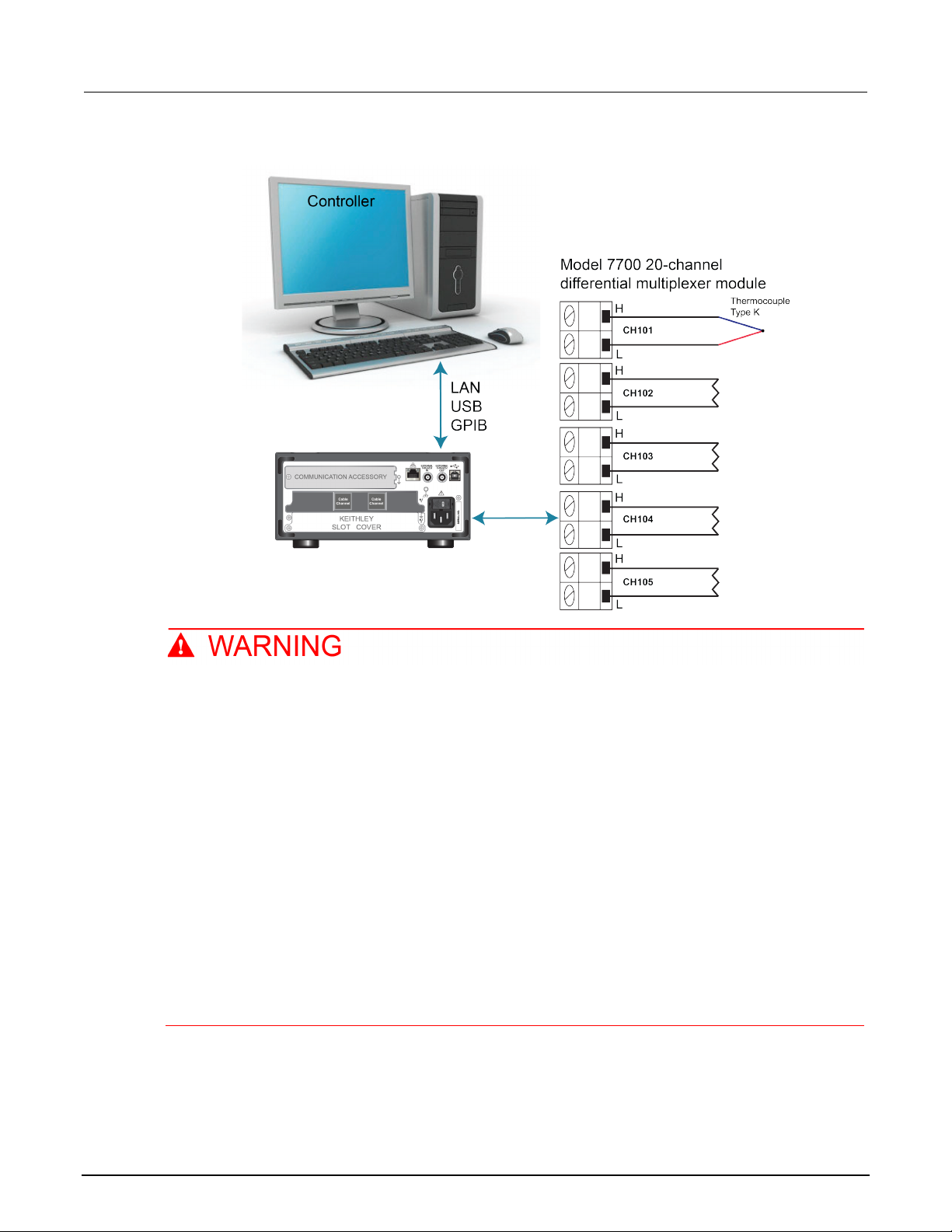
Section
User's Manual
10: Prescan monitor DAQ6510 Data Acquisition and Multim eter System
Figure 45: DAQ6510 prescan monitor device con nections
To prevent electric shock, test connections mu st be configured such that the user cannot
come in contact with test leads or any device un d er test (DUT) that is in contact with the
conductors. It is good practice to disconnect DUTs from the instrument before po wering the
instrument. Safe installation requires proper shields, barriers, and grounding to prevent
contact with test leads.
There is no internal connection between protective earth (safety ground) and the LO
terminals of the DAQ6510. Therefore, hazardous voltages (more than 30 V
) can appear on
RMS
LO terminals. This can occur when the instrument is operating in any mode. To prevent
hazardous voltage from appearing on the LO terminals, connect the LO terminal to protective
earth (safety ground) if your application allows it. You can connect the LO terminal to the
chassis ground terminal on the front panel or the chassis ground screw terminal on the rear
panel. Note that the front-panel terminals are isolated from the rear-panel terminals.
Therefore, if you are using the front-panel terminals, ground to the front-panel LO termi nal . I f
you are using the rear-panel terminals, ground to the rear-panel LO terminal. Failure to follow
these guidelines can result in injury, death, or instrument damage.
10-2 DAQ6510-900-01 Rev. B / August 2019
Page 94

DAQ6510
Prescan monitor
Data Acquisition and Multimeter System User's Manual Section 10:
Using the Monitor Measurement feature
The DAQ6510 uses Monitor Measurement triggering on channel 101.
For this application, you:
• Configure the instrument to measure the temper ature on channel 101 using a thermocouple.
• Configure the scan on channels 102 to 105 using the 2-wire resistance function. The instrument
Using the front panel
scans channels 102 to 105 after the specified temperature has been reached.
To setup the application from the front panel:
1. Press the POWER switch on the front panel to turn on the instrument.
2. Select the REAR terminals.
3. Press the MENU key.
4. Under Channel, select Scan.
5. Select the + button. Select channels 101 to 105 and select OK.
6. Select 2W Resistance on the Measure Functions screen.
7. In the upper left corner of the screen, select the menu and select Expand Group.
8. Select channel 101 by selecting the adjacent 2 Wire Res button.
9. In the Settings tab, set the Function to Temperature.
10. Set Reference Junction to Internal.
11. In the Scan tab, set the Scan Count to 10.
12. In the Trigger tab, set Scan Start to Monitor Measurement.
13. For Start Condition, select Above High Limit.
14. Set Channel to 101.
15. Set High Limit to 30 ˚C and select OK.
16. Select the Start button at the bottom of the left-side pane to start the scan.
17. Select View Scan Status to return to the home screen.
You can watch the active temperature measur em ent on channel 101. Once the target temperature is
reached, the instrument begins scanning.
DAQ6510-900-01 Rev. B / August 2019 10-3
Page 95

Section
ual
*RST
threshold
10: Prescan monitor DAQ6510 Data Acquisition and Multim eter System User's Man
Using SCPI commands
This sequence of SCPI commands executes a scan once the the environment reaches a target
temperature.
You may need to make changes so that this code will run in your programming environment. In the
table, the SCPI commands have a light gray background.
Send the following SCPI commands for this example application:
Commands Descriptions
FUNC "TEMP", (@101)
TEMP:TRAN TC, (@101)
TEMP:TC:TYPE K, (@101)
TEMP:UNIT CELS, (@101)
TEMP:TC:RJUN:RSEL INT, (@101)
ROUT:SCAN:MON:CHAN (@101)
ROUT:SCAN:MON:LIM:UPP 30
ROUT:SCAN:MON:MODE UPP
FUNC "RES", (@102:105)
RES:RANG:AUTO ON, (@102:105)
ROUT:SCAN:CREATE (@101:105)
ROUT:SCAN:COUN:SCAN 10
INIT
Put the instrument in a known state
Monitor temperature on channel 101
Set transducer type to thermocouple
Set the thermocouple type to K
Set units to Celsius
Set the reference junction to internal reference
Monitor channel 101
Set the upper limit to 30 °C
Set monitor mode to monitor the upper limit
Set the function to resistance for c hannels 102 through
105
Set auto range on
Create a scan that includes channels 101 through 105
Set the scan count to 10
Initiate the monitoring of channel 101 conditions, which
will enable the scan when it crosses the temperature
10-4 DAQ6510-900-01 Rev. B / August 2019
Page 96

DAQ6510
Prescan monitor
Data Acquisition and Multimeter System User's Manual Section 10:
Using TSP commands
The following TSP code is designed to be run from Keithley Instruments Test Script Builder (TSB).
TSB is a software tool that is available from tek.com/keithley
code and develop scripts for TSP-enabled instruments. Information about how to use TSB is in the
online help for TSB and in the “Introduction to TSP operat i on” section of the Model DAQ6510
Reference Manual.
To use other programming environments, you may need to make changes to the example TSP code.
By default, the DAQ6510 uses the SCPI command set. You must select the TSP command set before
sending TSP commands to the instrument.
To enable TSP commands:
1. Press the MENU key.
2. Under System, select Settings.
3. Set the Command Set to TSP.
4. At the prompt to reboot, select Yes.
. You can install and use TSB to write
This sequence of TSP commands monitors the temperature measurement on the first channel to
ensure the test environment has reached the required temperature to begin scanning. After the code
executes, the data is displayed in the Instrument Console of Test Script Builder.
Send the following commands for this example application:
-- Monitor temperature on channel 101.
reset()
channel.setdmm("101", dmm.ATTR_MEAS_FUNCTION, dmm.FUNC_TEMPERATURE,
dmm.ATTR_MEAS_TRANSDUCER, dmm.TRANS_THERMOCOUPLE, dmm.ATTR_MEAS_THERMOCOUPLE,
dmm.THERMOCOUPLE_K, dmm.ATTR_MEAS_REF_JUNCTION, dmm.REFJUNCT_INTERNAL)
channel.setdmm("101", dmm.ATTR_MEAS_UNIT, dmm.UNIT_CELSIUS)
-- Set the monitor to watch for the high limit and trigger the scan
-- when the high limit exceeds 30 C.
scan.monitor.channel = "101"
scan.monitor.limit.high.value = 30
scan.monitor.mode = scan.MODE_HIGH
-- Scan 2-wire resistance on channels 102:105.
channel.setdmm("102:105", dmm.ATTR_MEAS_FUNCTION, dmm.FUNC_RESISTANCE,
dmm.ATTR_MEAS_RANGE_AUTO, dmm.ON)
-- Create scan.
scan.create("101:105")
scan.scancount = 10
-- Initiates the monitoring of channel 101 conditions, which enables the scan
-- when it crosses the temperature threshold.
trigger.model.initiate()
DAQ6510-900-01 Rev. B / August 2019 10-5
Page 97

In this section:
What is the ethernet port number? ......................................... 11-6
About this section ................................................................... 11-1
Where can I find updated drivers? ......................................... 11-1
Is there any software to help me get started? ........................ 11-2
How do I upgrade the firmware? ............................................ 11-2
Why can't the DAQ6510 read my USB flas h drive? ............... 11-4
How do I change the command set? ...................................... 11-4
How do I save the present state of the inst rument? ............... 11-5
Why did my settings change? ................................................ 11-6
How do I save what is displayed on the screen? .................... 11-6
About this section
Section 11
Troubleshooting/FAQ
This section helps you find answers to the most common questions encountered with the DAQ6510.
Where can I find updated drivers?
For the latest drivers and additional support inf ormation, see the Keithley Instruments support
website.
To see what drivers are available for your instrument:
1. Go to tek.com/support
2. Enter the model number of your instrument.
3. Select Software from the filter list.
4. Select Driver from the filter list.
If you use the native LabVIEWTM or IVI driver, you must configure the DAQ6510 to use the SCPI
command set. For information on changing the command set, refer to How do I change the
command set? (on page 11-6)
.
Page 98

Section
User's Manual
11: Troubleshooting/FAQ DAQ6510 Data Acquisition and Multimeter System
Is there any software to help me get started?
Yes. Keithley provides KickStart Software and T est Script Builder to help you get started with the
DAQ6510.
KickStart Software is a program that allows you to set up your instrument and run a test without using
any programming languages.
Test Script Builder (TSB) is a software tool that simpl ifies building test scripts if you are using the Test
®
Script Processor (TSP
) scripting engine.
Both software options are available on tek.com/keithley
.
Why can't the DAQ6510 read my USB flash drive?
Verify that the flash drive is formatted with the FA T 32 file system. The DAQ6510 only supports FAT
and FAT32 drives using Master Boot Record (MBR).
®
In Microsoft
Windows®, you can check the file system by checking the properties of the USB flash
drive.
Higher capacity USB drives take longer to be re ad and loaded by the instrument.
Why did my settings change?
Many of the commands in the DAQ6510 are saved with the measure function that was active when
you set them. For example, assume you have the measure function set to current and you set a value
for display digits. When you change the measure f unction to voltage, the display digits value changes
to the value that was last set for the voltage measure function. When you return to the current
measure function, the display digits value retur ns t o the value you set previously.
11-2 DAQ6510-900-01 Rev. B / August 2019
Page 99

DAQ6510
Troubleshooting/FAQ
Data Acquisition and Multimeter System User's Manual Section 11:
How do I upgrade the firmware?
Do not turn off power or remove the USB flash drive until the upgrade process is complete.
The firmware file must be in the root subdirectory of the USB flash drive and must be the only
firmware file in that location. You can upgrade or downgrade the firmware from the front panel or
from the virtual front panel. Refer to “Using the DAQ6510 virtual front panel” in the Model DAQ6510
Reference Manual for information.
From the front panel:
1. Copy the firmware file (.upg file) to a USB flash drive.
2. Verify that the firmware file is in the root subdirectory of the flash drive and that it is the only
firmware file in that location.
3. Disconnect any terminals that are attached t o the instrument.
4. Turn the instrument power off. Wait a few seconds.
5. Turn the instrument power on.
6. Insert the flash drive into the USB port on the f ront panel of the instrument.
7. From the instrument front panel, press the MENU key.
8. Under System, select Info/Manage.
9. Choose an upgrade option:
To upgrade to a newer version of firmware, select Upgrade to New.
To return to a previous version of firmware, select Downgrade to Older.
10. If the instrument is controlled remotely, a message is display ed. Select Yes to continue.
11. When the upgrade is complete, reboot the instrument.
A message is displayed while the upgrade is in progress.
Upgrade files are available on tek.com/keithley
.
DAQ6510-900-01 Rev. B / August 2019 11-3
Page 100

Section
User's Manual
11: Troubleshooting/FAQ DAQ6510 Data Acquisition and Multim eter System
How do I change the command set?
You can change the command set that you use with t he DA Q6510. The remote command sets that
are available include:
• SCPI: An instrument-specific language built on the SCPI standard.
• TSP: A scripting programming language that cont ai ns instrument-specific control commands that
can be executed from a stand-alone instrument. You can use TSP to send individual commands
or use it to combine commands into scripts.
• SCPI2700: An instrument-specific langu age that allows you to run code developed for Keithley
Instruments Model 2700.
• SCPI2701: An instrument-specific langu age that allows you to run code developed for Keithley
Instruments Model 2701.
If you change the command set, reboot the instrument.
You cannot combine the command sets.
As delivered from Keithley Instruments, the DAQ 6510 is set to work with the SCPI command set.
If you choose the SCPI2700 or SCPI2701 comm and set, you will not have access to some of the
extended ranges and other features that are now avai lable using the default SCPI command set. In
addition, some Series 2700 code will work different l y in the DAQ6510 than it did in the earlier
instrument. See DAQ6510 in a Model 2700 or 2701 Application, Keithley Instruments document
number 0771465XX, for information about the differences.
To set the command set from the front panel:
1. Press the MENU key.
2. Under System, select Settings.
3. Select the appropriate Command Set.
You are prompted to confirm the change to the command set and reboot.
To verify which command set is selected from a remote interface:
Send the command:
*LANG?
11-4 DAQ6510-900-01 Rev. B / August 2019
 Loading...