

Page 1

User Manual
CTS 710
SONET Test Set
070-8852-03
This document applies to firmware version 1.3
and above.
Page 2

Copyright E Tektronix, Inc. 1994. All rights reserved. T ektronix products are covered by U.S. and foreign patents, issued and
pending. Information in this publication supercedes that in all previously
published material. Specifications and price change privileges reserved.
Tektronix, Inc., P.O. Box 500, Beaverton, OR, 97077
TEKTRONIX and TEK are registered trademarks of Tektronix, Inc.
Page 3

WARRANTY
Tektronix warrants that this product will be free from defects in materials and
workmanship for a period of three (3) years from the date of shipment. If any such product
proves defective during this warranty period, Tektronix, at its option, either will repair the
defective product without charge for parts and labor, or will provide a replacement in
exchange for the defective product.
In order to obtain service under this warranty, Customer must notify Tektronix of the
defect before the expiration of the warranty period and make suitable arrangements for the
performance of service. Customer shall be responsible for packaging and shipping the
defective product to the service center designated by Tektronix, with shipping charges
prepaid. Tektronix shall pay for the return of the product to Customer if the shipment is to
a location within the country in which the Tektronix service center is located. Customer
shall be responsible for paying all shipping charges, duties, taxes, and any other charges for
products returned to any other locations.
This warranty shall not apply to any defect, failure or damage caused by improper use or
improper or inadequate maintenance and care. Tektronix shall not be obligated to furnish
service under this warranty a) to repair damage resulting from attempts by personnel other
than Tektronix representatives to install, repair or service the product; b) to repair damage
resulting from improper use or connection to incompatible equipment; or c) to service a
product that has been modified or integrated with other products when the effect of such
modification or integration increases the time or difficulty of servicing the product.
THIS WARRANTY IS GIVEN BY TEKTRONIX WITH RESPECT TO THIS
PRODUCT IN LIEU OF ANY OTHER WARRANTIES, EXPRESSED OR
IMPLIED. TEKTRONIX AND ITS VENDORS DISCLAIM ANY IMPLIED
WARRANTIES OF MERCHANTABILITY OR FITNESS FOR A PARTICULAR
PURPOSE. TEKTRONIX’ RESPONSIBILITY TO REPAIR OR REPLACE
DEFECTIVE PRODUCTS IS THE SOLE AND EXCLUSIVE REMEDY
PROVIDED TO THE CUSTOMER FOR BREACH OF THIS WARRANTY.
TEKTRONIX AND ITS VENDORS WILL NOT BE LIABLE FOR ANY
INDIRECT, SPECIAL, INCIDENTAL, OR CONSEQUENTIAL DAMAGES
IRRESPECTIVE OF WHETHER TEKTRONIX OR THE VENDOR HAS
ADVANCE NOTICE OF THE POSSIBILITY OF SUCH DAMAGES.
Page 4

Page 5

Table of Contents
General Safety Summary xvii. . . . . . . . . . . . . . . . . . . . . . . . . . . .
Preface xxi. . . . . . . . . . . . . . . . . . . . . . . . . . . . . . . . . . . . . . . . . . . .
How This Manual is Organized xxi. . . . . . . . . . . . . . . . . . . . . . . . .
Conventions xxi. . . . . . . . . . . . . . . . . . . . . . . . . . . . . . . . . . . . . . . .
Related Manuals xxii. . . . . . . . . . . . . . . . . . . . . . . . . . . . . . . . . . . .
Using the CTS 710 Reference xxiii. . . . . . . . . . . . . . . . . . . . . . .
Getting Started
Getting Started 1–1. . . . . . . . . . . . . . . . . . . . . . . . . . . . . . . . . . . . .
Product Description 1–1. . . . . . . . . . . . . . . . . . . . . . . . . . . . . . . . . .
Accessories 1–2. . . . . . . . . . . . . . . . . . . . . . . . . . . . . . . . . . . . . . . .
Standard Accessories 1–2. . . . . . . . . . . . . . . . . . . . . . . . . . . . . .
Optional Accessories 1–2. . . . . . . . . . . . . . . . . . . . . . . . . . . . . .
First Time Operation 1–3. . . . . . . . . . . . . . . . . . . . . . . . . . . . . . . . .
Installing the Accessory Pouch 1–3. . . . . . . . . . . . . . . . . . . . . .
Setting Up the CTS 710 1–7. . . . . . . . . . . . . . . . . . . . . . . . . . . .
Turning On the CTS 710 1–9. . . . . . . . . . . . . . . . . . . . . . . . . . .
Turning Off the CTS 710 1–10. . . . . . . . . . . . . . . . . . . . . . . . . . .
Operating Basics
Functional Overview 2–1. . . . . . . . . . . . . . . . . . . . . . . . . . . . . . . .
Front-Panel Controls, Indicators, and Connectors 2–2. . . . . . . . . . .
Rear-Panel Controls and Connectors 2–4. . . . . . . . . . . . . . . . . . . . .
Front-Panel Status Lights 2–4. . . . . . . . . . . . . . . . . . . . . . . . . . . . .
Reading the Display 2–6. . . . . . . . . . . . . . . . . . . . . . . . . . . . . . . . . .
The Basic Menu Structure 2–9. . . . . . . . . . . . . . . . . . . . . . . . . . . . .
What is a Menu? 2–9. . . . . . . . . . . . . . . . . . . . . . . . . . . . . . . . .
Selecting Menus 2–11. . . . . . . . . . . . . . . . . . . . . . . . . . . . . . . . . .
Selecting Pages 2–11. . . . . . . . . . . . . . . . . . . . . . . . . . . . . . . . . .
Displaying Help 2–12. . . . . . . . . . . . . . . . . . . . . . . . . . . . . . . . . . . . .
Connecting Signals 2–13. . . . . . . . . . . . . . . . . . . . . . . . . . . . . . . . . .
Connecting Optical Signals 2–14. . . . . . . . . . . . . . . . . . . . . . . . .
Connecting SONET Electrical Signals 2–15. . . . . . . . . . . . . . . .
Connecting DS1/DS3 Electrical Signals 2–15. . . . . . . . . . . . . . .
Initiating Autoscan 2–15. . . . . . . . . . . . . . . . . . . . . . . . . . . . . . . . . . .
CTS 710 SONET Test Set User Manual
i
Page 6

T able of Contents
Changing Parameters 2–15. . . . . . . . . . . . . . . . . . . . . . . . . . . . . . . . .
Selecting Parameters 2–16. . . . . . . . . . . . . . . . . . . . . . . . . . . . . .
Selecting from Lists 2–16. . . . . . . . . . . . . . . . . . . . . . . . . . . . . . .
Changing Decimal Numbers 2–17. . . . . . . . . . . . . . . . . . . . . . . .
Changing Binary Numbers 2–20. . . . . . . . . . . . . . . . . . . . . . . . .
Entering T ext 2–21. . . . . . . . . . . . . . . . . . . . . . . . . . . . . . . . . . . .
Working with the Disk Drive 2–23. . . . . . . . . . . . . . . . . . . . . . . . . . .
Reading Files on Disk 2–24. . . . . . . . . . . . . . . . . . . . . . . . . . . . .
Tutorial 2–27. . . . . . . . . . . . . . . . . . . . . . . . . . . . . . . . . . . . . . . . . . .
Before Turning On the CTS 710 2–27. . . . . . . . . . . . . . . . . . . . . . . .
Setting Transmit Parameters 2–28. . . . . . . . . . . . . . . . . . . . . . . . . . .
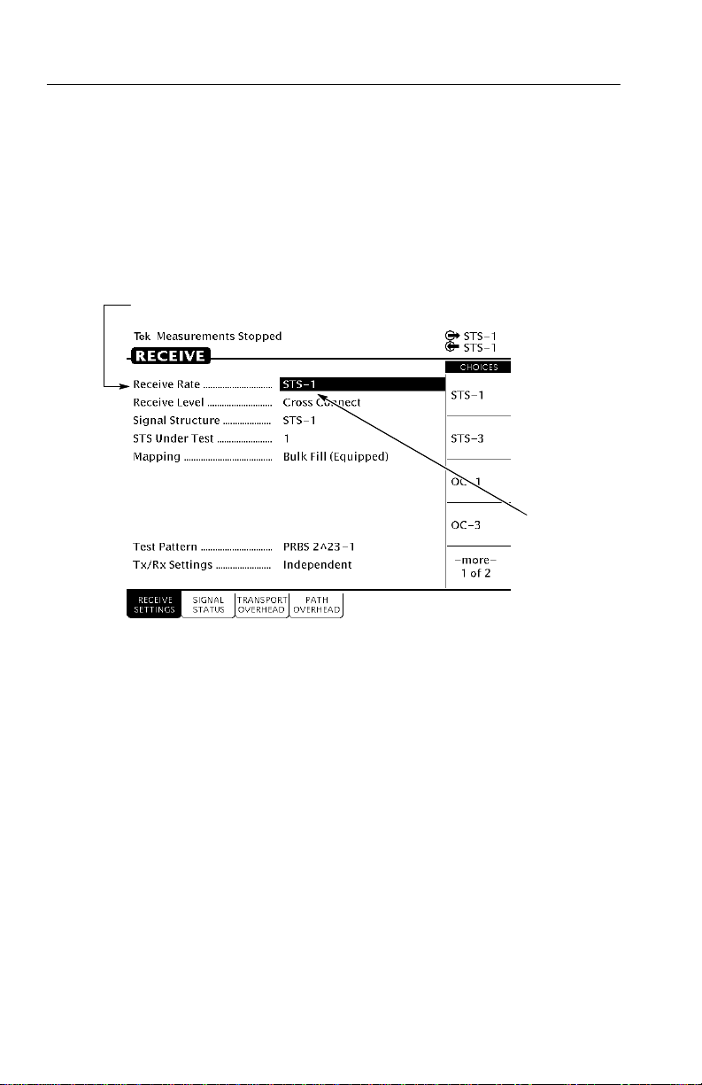
Setting Receive Parameters 2–30. . . . . . . . . . . . . . . . . . . . . . . . . . . .
Setting the T est Time 2–31. . . . . . . . . . . . . . . . . . . . . . . . . . . . . . . . .
Where Test Results Are Displayed 2–32. . . . . . . . . . . . . . . . . . . . . .
Begin the T est 2–33. . . . . . . . . . . . . . . . . . . . . . . . . . . . . . . . . . . . . .
Inserting Errors 2–34. . . . . . . . . . . . . . . . . . . . . . . . . . . . . . . . . . . . .
Adjusting Pointers 2–36. . . . . . . . . . . . . . . . . . . . . . . . . . . . . . . . . . .
Viewing Transport Overhead 2–40. . . . . . . . . . . . . . . . . . . . . . . . . . .
Editing the Transport Overhead 2–41. . . . . . . . . . . . . . . . . . . . . . . . .
Viewing Test Results 2–43. . . . . . . . . . . . . . . . . . . . . . . . . . . . . . . . .
Reference
Basic Test Procedures 3–1. . . . . . . . . . . . . . . . . . . . . . . . . . . . . . .
Setting Up the CTS 710 3–1. . . . . . . . . . . . . . . . . . . . . . . . . . . . . . .
Network Continuity Checking 3–2. . . . . . . . . . . . . . . . . . . . . . . . . .
Transmission Signal Quality Testing 3–4. . . . . . . . . . . . . . . . . . . . .
Measuring Bit Error Rate 3–4. . . . . . . . . . . . . . . . . . . . . . . . . . .
T esting Mapping and Demapping 3–6. . . . . . . . . . . . . . . . . . . .
Fault T olerance Checking 3–8. . . . . . . . . . . . . . . . . . . . . . . . . . . . .
Response to Errors and Alarms 3–8. . . . . . . . . . . . . . . . . . . . . .
Response to Pointer Movements 3–13. . . . . . . . . . . . . . . . . . . . .
Response to Line Frequency Offset 3–16. . . . . . . . . . . . . . . . . . .
Performance Monitoring 3–18. . . . . . . . . . . . . . . . . . . . . . . . . . . . . .
Setting Test Control Parameters 3–23. . . . . . . . . . . . . . . . . . . . . .
Setting the T est Time Duration 3–23. . . . . . . . . . . . . . . . . . . . . . . . .
Setting a Unique T est Time Duration 3–24. . . . . . . . . . . . . . . . .
Setting the History Resolution 3–26. . . . . . . . . . . . . . . . . . . . . . . . . .
ii
CTS 710 SONET T est Set User Manual
Page 7

T able of Contents
Starting and Stopping a T est 3–27. . . . . . . . . . . . . . . . . . . . . . . . . . .
Making Changes While Running a T est 3–28. . . . . . . . . . . . . . .
Actions You Cannot Perform While Running a Test 3–28. . . . . .
Working with Test Setups 3–31. . . . . . . . . . . . . . . . . . . . . . . . . . . .
Saving and Recalling Instrument Setups 3–31. . . . . . . . . . . . . . . . . .
Saving Instrument Setups 3–32. . . . . . . . . . . . . . . . . . . . . . . . . .
Recalling Instrument Setups 3–34. . . . . . . . . . . . . . . . . . . . . . . .
Recalling the Default Factory Setup 3–35. . . . . . . . . . . . . . . . . .
Deleting Instrument Setups from Disk 3–36. . . . . . . . . . . . . . . .
Pass/Fail T ests 3–37. . . . . . . . . . . . . . . . . . . . . . . . . . . . . . . . . . . . . .
Parameters of a Pass/Fail T est 3–37. . . . . . . . . . . . . . . . . . . . . . .
Fail If Conditions 3–38. . . . . . . . . . . . . . . . . . . . . . . . . . . . . . . . .
Creating a Pass/Fail T est 3–44. . . . . . . . . . . . . . . . . . . . . . . . . . . . . .
Running a Pass/Fail T est 3–49. . . . . . . . . . . . . . . . . . . . . . . . . . .
Changing an Existing Pass/Fail T est 3–51. . . . . . . . . . . . . . . . . .
Deleting a Pass/Fail T est from Disk 3–53. . . . . . . . . . . . . . . . . . .
Checking Signal Status 3–55. . . . . . . . . . . . . . . . . . . . . . . . . . . . . .
Viewing Signal Structure 3–55. . . . . . . . . . . . . . . . . . . . . . . . . . . . . .
Viewing the Payload (Add/Drop/Test Option Only) 3–56. . . . . .
Determining the Payload Pattern and Framing
(Add/Drop/T est Option Only) 3–57. . . . . . . . . . . . . . . . . . . .
Printing the AutoScan Dialog Box 3–58. . . . . . . . . . . . . . . . . . .
Viewing the Signal State 3–58. . . . . . . . . . . . . . . . . . . . . . . . . . . . . .
Extended Status 3–61. . . . . . . . . . . . . . . . . . . . . . . . . . . . . . . . . .
Setting the Beeper 3–61. . . . . . . . . . . . . . . . . . . . . . . . . . . . . . . .
Setting SONET T ransmit Parameters 3–63. . . . . . . . . . . . . . . . . .
Steps for Setting Parameters 3–63. . . . . . . . . . . . . . . . . . . . . . . . . . .
Setting the Transmit Rate 3–64. . . . . . . . . . . . . . . . . . . . . . . . . . . . .
Independent Transmit and Receive Settings 3–64. . . . . . . . . . . .
Coupling Transmit and Receive Settings 3–65. . . . . . . . . . . . . . .
Through Mode 3–67. . . . . . . . . . . . . . . . . . . . . . . . . . . . . . . . . . .
Setting the Transmit Clock 3–68. . . . . . . . . . . . . . . . . . . . . . . . . . . .
Setting the Transmit Level 3–69. . . . . . . . . . . . . . . . . . . . . . . . . . . . .
Setting the Signal Structure 3–69. . . . . . . . . . . . . . . . . . . . . . . . . . . .
Specifying the STS to T est 3–70. . . . . . . . . . . . . . . . . . . . . . . . . . . .
Setting the Payload Mapping 3–71. . . . . . . . . . . . . . . . . . . . . . . . . . .
Unequipped Payload Mapping 3–72. . . . . . . . . . . . . . . . . . . . . . .
CTS 710 SONET T est Set User Manual
iii
Page 8

T able of Contents
Mapping a Tributary Signal (Add/Drop/Test Option Only) 3–72. . .
Mapping a Tributary with VT1.5 Floating Async Payload
Setting the T est Pattern 3–75. . . . . . . . . . . . . . . . . . . . . . . . . . . . . . .
Setting Overhead Bytes 3–77. . . . . . . . . . . . . . . . . . . . . . . . . . . . . . .
How to Edit an Overhead Byte 3–77. . . . . . . . . . . . . . . . . . . . . .
Editing the V5 Byte 3–80. . . . . . . . . . . . . . . . . . . . . . . . . . . . . . .
Bytes You Cannot Edit 3–81. . . . . . . . . . . . . . . . . . . . . . . . . . . . .
Editing the J1 Path Trace Byte 3–82. . . . . . . . . . . . . . . . . . . . . . .
Adding DCC and User Channel Overhead Bytes 3–84. . . . . . . .
Setting Tributary Signal Transmit Parameters 3–89. . . . . . . . . .
Steps for Setting Parameters 3–89. . . . . . . . . . . . . . . . . . . . . . . . . . .
Setting the Transmit Rate 3–90. . . . . . . . . . . . . . . . . . . . . . . . . . . . .
Independent Transmit and Receive Settings 3–90. . . . . . . . . . . .
Coupling Transmit and Receive Settings 3–90. . . . . . . . . . . . . . .
Setting the Transmit Clock 3–92. . . . . . . . . . . . . . . . . . . . . . . . . . . .
Setting the Line Clock Offset 3–93. . . . . . . . . . . . . . . . . . . . . . . . . .
Setting the Transmit Line Code 3–93. . . . . . . . . . . . . . . . . . . . . . . . .
Specifying the Framing 3–94. . . . . . . . . . . . . . . . . . . . . . . . . . . . . . .
Specifying the T est Pattern 3–96. . . . . . . . . . . . . . . . . . . . . . . . . . . .
Setting SONET Receive Parameters 3–99. . . . . . . . . . . . . . . . . . .
Steps for Setting Parameters 3–99. . . . . . . . . . . . . . . . . . . . . . . . . . .
Setting the Receive Rate 3–100. . . . . . . . . . . . . . . . . . . . . . . . . . . . . .
Independent Receive and Transmit Settings 3–101. . . . . . . . . . . .
Coupling Receive and Transmit Settings 3–101. . . . . . . . . . . . . . .
Setting the Receive Level 3–103. . . . . . . . . . . . . . . . . . . . . . . . . . . . .
Setting the Signal Structure 3–103. . . . . . . . . . . . . . . . . . . . . . . . . . . .
Specifying Which STS to T est 3–104. . . . . . . . . . . . . . . . . . . . . . . . . .
Setting the Mapping 3–104. . . . . . . . . . . . . . . . . . . . . . . . . . . . . . . . . .
Demultiplexing a DS1 from a DS3 Mapped in a SONET Signal
(Add/Drop/T est Option Only) 3–107. . . . . . . . . . . . . . . . . . . . . . .
Demapping a Tributary Signal (Add/Drop/Test Option Only) 3–110.
Dropping a Tributary Signal 3–111. . . . . . . . . . . . . . . . . . . . . . . . . . .
Setting the T est Pattern 3–113. . . . . . . . . . . . . . . . . . . . . . . . . . . . . . .
Unequipped Payload Mapping 3–114. . . . . . . . . . . . . . . . . . . . . . .
Checking Received Optical Power or Received Peak Voltage 3–114.
Mapping 3–72. . . . . . . . . . . . . . . . . . . . . . . . . . . . . . . . . . . . .
iv
CTS 710 SONET T est Set User Manual
Page 9

T able of Contents
Viewing Overhead Bytes 3–115. . . . . . . . . . . . . . . . . . . . . . . . . . . . . .
Viewing Transport Overhead Bytes 3–115. . . . . . . . . . . . . . . . . . .
Viewing Path Overhead Bytes 3–116. . . . . . . . . . . . . . . . . . . . . . .
Displaying the J1 Path Trace Message 3–116. . . . . . . . . . . . . . . . .
Displaying the V5 Byte 3–117. . . . . . . . . . . . . . . . . . . . . . . . . . . .
Dropping DCC and User Channel Overhead Bytes 3–117. . . . . . .
Controlling the Display Update 3–120. . . . . . . . . . . . . . . . . . . . . .
Setting Tributary Receive Parameters 3–121. . . . . . . . . . . . . . . . . .
Steps for Setting Parameters 3–121. . . . . . . . . . . . . . . . . . . . . . . . . . .
Setting the Receive Rate 3–122. . . . . . . . . . . . . . . . . . . . . . . . . . . . . .
Independent Receive and Transmit Settings 3–123. . . . . . . . . . . .
Coupling Receive and Transmit Settings 3–123. . . . . . . . . . . . . . .
Setting the Receive Level 3–124. . . . . . . . . . . . . . . . . . . . . . . . . . . . .
Setting the Framing 3–124. . . . . . . . . . . . . . . . . . . . . . . . . . . . . . . . . .
Specifying the T est Pattern 3–125. . . . . . . . . . . . . . . . . . . . . . . . . . . .
Demultiplexing a DS1 from a DS3 Signal 3–127. . . . . . . . . . . . . . . .
Setting Alarms and Inserting Errors 3–131. . . . . . . . . . . . . . . . . . .
Simulating Error Conditions 3–131. . . . . . . . . . . . . . . . . . . . . . . . . . .
Specifying the Error to Insert 3–132. . . . . . . . . . . . . . . . . . . . . . . .
Inserting Errors 3–133. . . . . . . . . . . . . . . . . . . . . . . . . . . . . . . . . .
Setting Alarms 3–135. . . . . . . . . . . . . . . . . . . . . . . . . . . . . . . . . . . . . .
Simulating Transmit Failures 3–138. . . . . . . . . . . . . . . . . . . . . . . . . . .
Setting Pointers and Changing Timing 3–141. . . . . . . . . . . . . . . . .
Setting Pointers 3–141. . . . . . . . . . . . . . . . . . . . . . . . . . . . . . . . . . . . .
Manual Pointer Control 3–142. . . . . . . . . . . . . . . . . . . . . . . . . . . .
Continuous Pointer Movement 3–147. . . . . . . . . . . . . . . . . . . . . .
Changing Timing 3–149. . . . . . . . . . . . . . . . . . . . . . . . . . . . . . . . . . . .
Generating Pointer Sequences 3–151. . . . . . . . . . . . . . . . . . . . . . . . . .
Starting Pointer Sequences 3–156. . . . . . . . . . . . . . . . . . . . . . . . .
Testing Automatic Protection Switching 3–161. . . . . . . . . . . . . . . .
Setting the APS Mode 3–161. . . . . . . . . . . . . . . . . . . . . . . . . . . . . . . .
Setting the K1 Byte 3–162. . . . . . . . . . . . . . . . . . . . . . . . . . . . . . . . . .
Setting the K2 Byte 3–166. . . . . . . . . . . . . . . . . . . . . . . . . . . . . . . . . .
Transmitting the K1 and K2 Bytes 3–170. . . . . . . . . . . . . . . . . . . . . .
Viewing the Network Response to APS Commands 3–172. . . . . . . . .
Viewing Results 3–173. . . . . . . . . . . . . . . . . . . . . . . . . . . . . . . . . . . .
Viewing a Summary of Results 3–173. . . . . . . . . . . . . . . . . . . . . . . . .
CTS 710 SONET T est Set User Manual
v
Page 10

T able of Contents
Viewing Detailed Results 3–174. . . . . . . . . . . . . . . . . . . . . . . . . . . . .
Displaying an Overview of T est Results 3–175. . . . . . . . . . . . . . .
Displaying an Analysis of T est Results 3–177. . . . . . . . . . . . . . . .
Viewing Measurement Histories 3–181. . . . . . . . . . . . . . . . . . . . . . . .
T ypes of Graphs 3–182. . . . . . . . . . . . . . . . . . . . . . . . . . . . . . . . . .
Elements of the History Graph Display 3–186. . . . . . . . . . . . . . . . . . .
Graph Name 3–186. . . . . . . . . . . . . . . . . . . . . . . . . . . . . . . . . . . . .
History Resolution 3–186. . . . . . . . . . . . . . . . . . . . . . . . . . . . . . . .
Power Out Indicator 3–187. . . . . . . . . . . . . . . . . . . . . . . . . . . . . . .
Cursor 3–187. . . . . . . . . . . . . . . . . . . . . . . . . . . . . . . . . . . . . . . . . .
Cursor Position 3–187. . . . . . . . . . . . . . . . . . . . . . . . . . . . . . . . . . .
Measurement Results at Cursor Position 3–187. . . . . . . . . . . . . . .
Zooming History Graphs 3–188. . . . . . . . . . . . . . . . . . . . . . . . . . . . . .
Panning History Graphs 3–190. . . . . . . . . . . . . . . . . . . . . . . . . . . . . . .
Changing the Displayed History Graph 3–190. . . . . . . . . . . . . . . . . . .
Displaying Mini-Graphs 3–191. . . . . . . . . . . . . . . . . . . . . . . . . . .
Saving and Recalling Results 3–192. . . . . . . . . . . . . . . . . . . . . . . . . .
Saving T est Results to Disk 3–192. . . . . . . . . . . . . . . . . . . . . . . . .
Recalling T est Results from Disk 3–194. . . . . . . . . . . . . . . . . . . . .
Deleting T est Results from Disk 3–195. . . . . . . . . . . . . . . . . . . . .
Recalling T est Results from Memory 3–196. . . . . . . . . . . . . . . . .
Printing Results 3–196. . . . . . . . . . . . . . . . . . . . . . . . . . . . . . . . . . . . .
Printing Main Results or Error Analysis 3–196. . . . . . . . . . . . . . .
Printing History Graphs 3–198. . . . . . . . . . . . . . . . . . . . . . . . . . . .
Changing Instrument Settings 3–199. . . . . . . . . . . . . . . . . . . . . . . .
Viewing the Instrument Configuration 3–199. . . . . . . . . . . . . . . . . . .
Setting the Display Brightness 3–200. . . . . . . . . . . . . . . . . . . . . . . . . .
Turning the Beeper On and Off 3–201. . . . . . . . . . . . . . . . . . . . . . . . .
Setting the Date 3–202. . . . . . . . . . . . . . . . . . . . . . . . . . . . . . . . . . . . .
Setting the Time 3–202. . . . . . . . . . . . . . . . . . . . . . . . . . . . . . . . . . . . .
Changing the Printer Setup 3–203. . . . . . . . . . . . . . . . . . . . . . . . . . . .
Specifying the Printer or File T ype 3–204. . . . . . . . . . . . . . . . . . .
Setting RS-232 Parameters 3–204. . . . . . . . . . . . . . . . . . . . . . . . .
Setting the Print User & Company T ext 3–206. . . . . . . . . . . . . . .
Setting Remote Control Parameters 3–206. . . . . . . . . . . . . . . . . . . . . .
Setting the GPIB Address 3–207. . . . . . . . . . . . . . . . . . . . . . . . . .
Setting RS-232 Parameters 3–208. . . . . . . . . . . . . . . . . . . . . . . . .
vi
CTS 710 SONET T est Set User Manual
Page 11

Running Instrument Self T ests 3–210. . . . . . . . . . . . . . . . . . . . . . . . . .
Running the Power Up Self T est 3–211. . . . . . . . . . . . . . . . . . . . .
Appendices
Appendix A: Menu Maps A–1. . . . . . . . . . . . . . . . . . . . . . . . . . . .
TEST CONTROL Page A–1. . . . . . . . . . . . . . . . . . . . . . . . . . . . . . .
RECALL INSTRUMENT SETUPS Page A–1. . . . . . . . . . . . . . . . .
RECALL PASS/FAIL TESTS Page A–2. . . . . . . . . . . . . . . . . . . . .
SAVE INSTRUMENT SETUPS Page A–2. . . . . . . . . . . . . . . . . . .
SAVE PASS/FAIL TESTS Page A–3. . . . . . . . . . . . . . . . . . . . . . . .
TRANSMIT SETTINGS Page (1 of 2) A–4. . . . . . . . . . . . . . . . . . .
TRANSMIT SETTINGS Page (2 of 2) A–5. . . . . . . . . . . . . . . . . . .
ERRORS & ALARMS Page (1 of 4) A–6. . . . . . . . . . . . . . . . . . . .
ERRORS & ALARMS Page (2 of 4) A–7. . . . . . . . . . . . . . . . . . . .
ERRORS & ALARMS Page (3 of 4) A–8. . . . . . . . . . . . . . . . . . . .
ERRORS & ALARMS Page (4 of 4) A–9. . . . . . . . . . . . . . . . . . . .
POINTERS & TIMING Page (1 of 3) A–10. . . . . . . . . . . . . . . . . . . .
POINTERS & TIMING Page (2 of 3) A–11. . . . . . . . . . . . . . . . . . . .
POINTERS & TIMING Page (3 of 3) A–12. . . . . . . . . . . . . . . . . . . .
APS COMMANDS Page (1 of 3) A–13. . . . . . . . . . . . . . . . . . . . . . .
APS COMMANDS Page (2 of 3) A–14. . . . . . . . . . . . . . . . . . . . . . .
APS COMMANDS Page (3 of 3) A–15. . . . . . . . . . . . . . . . . . . . . . .
TRANSPORT OVERHEAD Page A–16. . . . . . . . . . . . . . . . . . . . . .
PA TH OVERHEAD Page A–17. . . . . . . . . . . . . . . . . . . . . . . . . . . . .
RECEIVE SETTINGS Page (1 of 2) A–18. . . . . . . . . . . . . . . . . . . . .
RECEIVE SETTINGS Page (2 of 2) A–19. . . . . . . . . . . . . . . . . . . . .
SIGNAL STATUS Page A–20. . . . . . . . . . . . . . . . . . . . . . . . . . . . . .
TRANSPORT OVERHEAD Page A–20. . . . . . . . . . . . . . . . . . . . . .
PA TH OVERHEAD Page A–21. . . . . . . . . . . . . . . . . . . . . . . . . . . . .
TEST SUMMARY Page A–21. . . . . . . . . . . . . . . . . . . . . . . . . . . . . .
MAIN RESULTS Page A–22. . . . . . . . . . . . . . . . . . . . . . . . . . . . . . .
ERROR ANALYSIS Page A–22. . . . . . . . . . . . . . . . . . . . . . . . . . . . .
HISTORY GRAPHS Page A–23. . . . . . . . . . . . . . . . . . . . . . . . . . . . .
SAVE RESULTS Page A–24. . . . . . . . . . . . . . . . . . . . . . . . . . . . . . . .
RECALL RESULTS Page A–24. . . . . . . . . . . . . . . . . . . . . . . . . . . . .
MISC SETTINGS Page A–24. . . . . . . . . . . . . . . . . . . . . . . . . . . . . . .
PRINTER SETUP Page A–25. . . . . . . . . . . . . . . . . . . . . . . . . . . . . . .
REMOTE CONTROL Page A–26. . . . . . . . . . . . . . . . . . . . . . . . . . .
INSTR CONFIG Page A–27. . . . . . . . . . . . . . . . . . . . . . . . . . . . . . . .
SELF TEST Page A–27. . . . . . . . . . . . . . . . . . . . . . . . . . . . . . . . . . . .
T able of Contents
CTS 710 SONET T est Set User Manual
vii
Page 12

Table of Contents
Appendix B: Status and Error Messages B–1. . . . . . . . . . . . . . . .
Status Messages B–1. . . . . . . . . . . . . . . . . . . . . . . . . . . . . . . . . . . . .
Error Messages B–3. . . . . . . . . . . . . . . . . . . . . . . . . . . . . . . . . . . . .
Appendix C: Default Factory Settings C–1. . . . . . . . . . . . . . . . . .
Appendix D: Specifications D–1. . . . . . . . . . . . . . . . . . . . . . . . . . .
Appendix E: Incoming Inspection Test E–1. . . . . . . . . . . . . . . . .
Loop-Back Connection E–2. . . . . . . . . . . . . . . . . . . . . . . . . . . . . . .
How to Proceed E–3. . . . . . . . . . . . . . . . . . . . . . . . . . . . . . . . . . . . .
System Self T est with External Loop-Back E–3. . . . . . . . . . . . . . . .
SONET Signals E–4. . . . . . . . . . . . . . . . . . . . . . . . . . . . . . . . . . . . .
Tributary Signals (Add/Drop/Test Option Only) E–6. . . . . . . . . . . .
Appendix F: Example Disk Contents F–1. . . . . . . . . . . . . . . . . . .
Instrument Setups F–1. . . . . . . . . . . . . . . . . . . . . . . . . . . . . . . . . . .
T est Results F–1. . . . . . . . . . . . . . . . . . . . . . . . . . . . . . . . . . . . . . . .
Pass/Fail T ests F–1. . . . . . . . . . . . . . . . . . . . . . . . . . . . . . . . . . . . . .
Appendix G: Rear-Panel Connectors G–1. . . . . . . . . . . . . . . . . .
VGA Video Output G–1. . . . . . . . . . . . . . . . . . . . . . . . . . . . . . . . . .
GPIB Port G–3. . . . . . . . . . . . . . . . . . . . . . . . . . . . . . . . . . . . . . . . . .
RS-232 Port G–3. . . . . . . . . . . . . . . . . . . . . . . . . . . . . . . . . . . . . . . .
External Clock Input G–4. . . . . . . . . . . . . . . . . . . . . . . . . . . . . . . . .
Calibration Signal Output G–4. . . . . . . . . . . . . . . . . . . . . . . . . . . . .
Overhead Add/Drop Port G–5. . . . . . . . . . . . . . . . . . . . . . . . . . . . . .
BITS Timing Reference Input G–7. . . . . . . . . . . . . . . . . . . . . . . . . .
Appendix H: Changing Optical Port Connectors H–1. . . . . . . . .
Cleaning the Optical Ports H–1. . . . . . . . . . . . . . . . . . . . . . . . . . . . .
Changing the Optical Port Connectors H–2. . . . . . . . . . . . . . . . . . .
Appendix I: Packing for Shipment I–1. . . . . . . . . . . . . . . . . . . .
Glossary and Index
viii
CTS 710 SONET T est Set User Manual
Page 13

List of Figures
Figure i: Placing the Reference for Easy Viewing xxiii. . . . . . . .
Figure 1–1: Installing the Accessory Pouch 1–4. . . . . . . . . . . . .
Figure 1–2: Inserting the Pouch Under the Front Panel
Trim 1–5. . . . . . . . . . . . . . . . . . . . . . . . . . . . . . . . . . . . . . . . . . .
Figure 1–3: Location of the D-Ring on the Accessory Pouch 1–6
Figure 1–4: Rear-Panel Controls and Connectors Used
in Setup 1–8. . . . . . . . . . . . . . . . . . . . . . . . . . . . . . . . . . . . . . . .
Figure 1–5: ON/STBY Button 1–10. . . . . . . . . . . . . . . . . . . . . . . .
Figure 2–1: Controls Located Around the Display 2–2. . . . . . . .
Figure 2–2: Front-Panel Controls, Indicators, and
Connectors 2–3. . . . . . . . . . . . . . . . . . . . . . . . . . . . . . . . . . . . .
Figure 2–3: Rear-Panel Controls and Connectors 2–4. . . . . . . .
Figure 2–4: Status Lights (With Option 22 Installed) 2–5. . . . .
Figure 2–5: Major Areas of the Display 2–6. . . . . . . . . . . . . . . .
Figure 2–6: Specific Elements of the Display 2–7. . . . . . . . . . . .
Figure 2–7: The Five Menus 2–9. . . . . . . . . . . . . . . . . . . . . . . . . .
Figure 2–8: Menus and Pages 2–10. . . . . . . . . . . . . . . . . . . . . . . . .
Figure 2–9: Menu Select Buttons 2–11. . . . . . . . . . . . . . . . . . . . . .
Figure 2–10: How to Display a Page 2–12. . . . . . . . . . . . . . . . . . .
Figure 2–11: Help Dialog Box 2–13. . . . . . . . . . . . . . . . . . . . . . . . .
Figure 2–12: Selecting a Parameter 2–16. . . . . . . . . . . . . . . . . . . .
Figure 2–13: Selecting Choices From a List 2–17. . . . . . . . . . . . .
Figure 2–14: Selecting USER DEFINED 2–18. . . . . . . . . . . . . . . .
Figure 2–15: Entering a Numeric Value 2–19. . . . . . . . . . . . . . . .
Figure 2–16: Selecting a Byte for Editing 2–20. . . . . . . . . . . . . . .
Figure 2–17: Editing a Byte 2–21. . . . . . . . . . . . . . . . . . . . . . . . . .
Figure 2–18: Selecting a Text String for Editing 2–22. . . . . . . . .
Table of Contents
CTS 710 SONET T est Set User Manual
ix
Page 14

T able of Contents
Figure 2–19: Editing a Text String 2–23. . . . . . . . . . . . . . . . . . . . .
Figure 2–20: Setup for the Tutorial 2–28. . . . . . . . . . . . . . . . . . . .
Figure 2–21: The TRANSMIT SETTINGS Page of the
TRANSMIT Menu 2–29. . . . . . . . . . . . . . . . . . . . . . . . . . . . . . .
Figure 2–22: The TEST TIME Page of the UTILITY Menu 2–31
Figure 2–23: The TEST SUMMARY Page of the RESULTS
Menu 2–32. . . . . . . . . . . . . . . . . . . . . . . . . . . . . . . . . . . . . . . . . .
Figure 2–24: The MAIN RESULTS Page of the RESULTS
Menu 2–33. . . . . . . . . . . . . . . . . . . . . . . . . . . . . . . . . . . . . . . . . .
Figure 2–25: The Message Line and Test Status Indicator 2–34.
Figure 2–26: The ERRORS & ALARMS Page of the
TRANSMIT Menu 2–35. . . . . . . . . . . . . . . . . . . . . . . . . . . . . . .
Figure 2–27: The POINTERS & TIMING Page of the
TRANSMIT Menu 2–37. . . . . . . . . . . . . . . . . . . . . . . . . . . . . . .
Figure 2–28: Adjusting Frequency Offset Using the Knob 2–39.
Figure 2–29: The TRANSPORT OVERHEAD Page of
the TRANSMIT Menu 2–41. . . . . . . . . . . . . . . . . . . . . . . . . . . .
Figure 2–30: The Display in Edit Mode 2–42. . . . . . . . . . . . . . . . .
Figure 2–31: The TEST SUMMARY Page of the RESULTS
Menu 2–44. . . . . . . . . . . . . . . . . . . . . . . . . . . . . . . . . . . . . . . . . .
Figure 2–32: The MAIN RESULTS Page of the RESULTS
Menu 2–45. . . . . . . . . . . . . . . . . . . . . . . . . . . . . . . . . . . . . . . . . .
Figure 3–1: Setup to Check Network Continuity 3–2. . . . . . . . .
Figure 3–2: Setup to Check a Transmission Link 3–4. . . . . . . . .
Figure 3–3: Setup to Test Mapping and Demapping 3–6. . . . . .
Figure 3–4: Setup to Check Error and Alarm Response 3–9. . .
Figure 3–5: Setup to Check Pointer Movements 3–14. . . . . . . . .
Figure 3–6: Setup to Check Line Frequency Offset
Response 3–16. . . . . . . . . . . . . . . . . . . . . . . . . . . . . . . . . . . . . . .
Figure 3–7: Setup to Monitor Performance 3–19. . . . . . . . . . . . .
Figure 3–8: The Test Control Page 3–24. . . . . . . . . . . . . . . . . . . . .
Figure 3–9: Setting a USER DEFINED Test Duration 3–25. . . .
x
CTS 710 SONET T est Set User Manual
Page 15

T able of Contents
Figure 3–10: Elapsed Time and Bar Graph Indicators 3–28. . . .
Figure 3–11: The SAVE INSTRUMENT SETUPS Page 3–33. . .
Figure 3–12: The RECALL INSTRUMENT SETUPS Page 3–35
Figure 3–13: Selecting a Disk File for Deleting 3–36. . . . . . . . . . .
Figure 3–14: The SAVE PASS/FAIL TESTS Page 3–37. . . . . . . .
Figure 3–15: Entering Fail If Conditions 3–47. . . . . . . . . . . . . . .
Figure 3–16: The TEST BEGIN Dialog Box 3–51. . . . . . . . . . . . .
Figure 3–17: Selecting a Pass/Fail Test for Deleting 3–53. . . . . . .
Figure 3–18: The AUTOSCAN Dialog Box Showing Signal
Structure 3–56. . . . . . . . . . . . . . . . . . . . . . . . . . . . . . . . . . . . . . .
Figure 3–19: Viewing Tributary Signal Structure 3–57. . . . . . . .
Figure 3–20: The Meaning of the Icons in the Autoscan
Dialog Box 3–58. . . . . . . . . . . . . . . . . . . . . . . . . . . . . . . . . . . . . .
Figure 3–21: Front-Panel Status Lights (with Add/Drop/Test
Option Installed) 3–59. . . . . . . . . . . . . . . . . . . . . . . . . . . . . . . .
Figure 3–22: Sequence for Setting SONET Signal
Parameters 3–63. . . . . . . . . . . . . . . . . . . . . . . . . . . . . . . . . . . . .
Figure 3–23: Sequence for Setting SONET Signal
Parameters When Mapping a T ributary Signal 3–64. . . . . . .
Figure 3–24: SONET Transmit Rates 3–65. . . . . . . . . . . . . . . . . .
Figure 3–25: CTS 710 in Through Mode 3–68. . . . . . . . . . . . . . . .
Figure 3–26: Mapping a Tributary Signal 3–73. . . . . . . . . . . . . . .
Figure 3–27: Editing the User Word Byte 3–77. . . . . . . . . . . . . . .
Figure 3–28: Editing the Z2 Transmit Overhead Byte 3–79. . . . .
Figure 3–29: Editing an Overhead Byte 3–80. . . . . . . . . . . . . . . .
Figure 3–30: Editing the J1 Path Trace Byte 3–84. . . . . . . . . . . .
Figure 3–31: Adding Data into the DCC 3–86. . . . . . . . . . . . . . . .
Figure 3–32: Adding Data into the User Channel 3–87. . . . . . . . .
Figure 3–33: Sequence for Setting Tributary Signal
Parameters 3–89. . . . . . . . . . . . . . . . . . . . . . . . . . . . . . . . . . . . .
Figure 3–34: Tributary Transmit Rates 3–91. . . . . . . . . . . . . . . . .
Figure 3–35: Editing the User Word 3–97. . . . . . . . . . . . . . . . . . .
CTS 710 SONET T est Set User Manual
xi
Page 16

T able of Contents
Figure 3–36: Sequence for Setting SONET Signal
Parameters 3–99. . . . . . . . . . . . . . . . . . . . . . . . . . . . . . . . . . . . .
Figure 3–37: Sequence for Setting SONET Signal
Parameters When Demapping a T ributary Signal 3–100. . . . .
Figure 3–38: SONET Receive Rates 3–101. . . . . . . . . . . . . . . . . . . .
Figure 3–39: Setting Tributary Mapping 3–110. . . . . . . . . . . . . . .
Figure 3–40: Displaying Received Optical Power 3–115. . . . . . . . .
Figure 3–41: J1 Path Trace Message Received by the
CTS 710 3–117. . . . . . . . . . . . . . . . . . . . . . . . . . . . . . . . . . . . . . . .
Figure 3–42: Dropping Data from the DCC 3–118. . . . . . . . . . . . .
Figure 3–43: Dropping the User Channel Data Byte 3–119. . . . . .
Figure 3–44: Sequence for Setting Tributary Signal
Parameters 3–121. . . . . . . . . . . . . . . . . . . . . . . . . . . . . . . . . . . . .
Figure 3–45: Sequence for Setting Signal Parameters to
Demultiplex a DS1 from a DS3 3–121. . . . . . . . . . . . . . . . . . . . .
Figure 3–46: Tributary Signal Receive Rates 3–122. . . . . . . . . . . .
Figure 3–47: Setting An Error Rate 3–135. . . . . . . . . . . . . . . . . . . .
Figure 3–48: Manual Pointer Control Choices 3–142. . . . . . . . . . .
Figure 3–49: Alternating Burst Pointer Movement 3–144. . . . . . .
Figure 3–50: Incrementing Pointer Location Once Every
T wo Milliseconds 3–149. . . . . . . . . . . . . . . . . . . . . . . . . . . . . . . .
Figure 3–51: Offsetting the Transmit Rate by +4.6 ppm 3–151. . .
Figure 3–52: The Three Periods of a Pointer Sequence 3–152. . . .
Figure 3–53: An Example of a Pointer Sequence 3–153. . . . . . . . .
Figure 3–54: Status Display While Pointer Sequences are
Running 3–160. . . . . . . . . . . . . . . . . . . . . . . . . . . . . . . . . . . . . . . .
Figure 3–55: The APS COMMANDS Page 3–162. . . . . . . . . . . . . .
Figure 3–56: The RECEIVE Column on the
APS COMMANDS Page 3–172. . . . . . . . . . . . . . . . . . . . . . . . . .
Figure 3–57: The Test Summary Page 3–174. . . . . . . . . . . . . . . . . .
Figure 3–58: Bar Graphs Showing Code Violations and
Errored Seconds 3–182. . . . . . . . . . . . . . . . . . . . . . . . . . . . . . . . .
xii
CTS 710 SONET T est Set User Manual
Page 17

T able of Contents
Figure 3–59: Line Graph Showing Pointer Value 3–184. . . . . . . . .
Figure 3–60: On/Off Graphs Showing Failures and Alarms 3–185
Figure 3–61: Elements of a History Graph 3–188. . . . . . . . . . . . . .
Figure 3–62: Changing the Displayed History Graph 3–191. . . . .
Figure 3–63: The SAVE RESULTS Page 3–193. . . . . . . . . . . . . . . .
Figure 3–64: The RECALL RESULTS Page 3–195. . . . . . . . . . . .
Figure 3–65: The PRINT CONTROL Dialog Box 3–197. . . . . . . .
Figure 3–66: The MISC SETTINGS Page 3–201. . . . . . . . . . . . . .
Figure 3–67: The PRINTER SETUP Page 3–203. . . . . . . . . . . . . .
Figure 3–68: The REMOTE CONTROL Page 3–208. . . . . . . . . . .
Figure E–1: Front-Panel Status Lights E–1. . . . . . . . . . . . . . . . .
Figure G–1: CTS 710 Rear Panel Connectors G–1. . . . . . . . . . .
Figure G–2: The VGA V ideo Output Connector G–2. . . . . . . . .
Figure G–3: The RS-232 Port G–3. . . . . . . . . . . . . . . . . . . . . . . . .
Figure G–4: The Overhead Add/Drop Port G–5. . . . . . . . . . . . .
Figure H–1: Removing the Optical Bulkhead Connector H–2. .
Figure H–2: FC Optical Bulkhead Assembly H–3. . . . . . . . . . . .
Figure H–3: ST Optical Bulkhead Assembly H–3. . . . . . . . . . . .
Figure H–4: DIN 47256 Optical Bulkhead Assembly H–4. . . . . .
Figure H–5: SC Optical Bulkhead Assembly H–4. . . . . . . . . . . .
CTS 710 SONET T est Set User Manual
xiii
Page 18

T able of Contents
List of Tables
Table 1–1: Fuse and Fuse Cap Part Numbers 1–8. . . . . . . . . . .
Table 1–2: Power Requirements 1–9. . . . . . . . . . . . . . . . . . . . . .
Table 2–1: Icons that Appear in the Display 2–8. . . . . . . . . . . .
Table 2–2: CTS 710 Disk File Types 2–24. . . . . . . . . . . . . . . . . . .
Table 3–1: LTE Responses to Errors and Alarms 3–9. . . . . . . .
Table 3–2: T est Duration Limits 3–26. . . . . . . . . . . . . . . . . . . . . .
Table 3–3: Actions You Cannot Perform While a Test
is Running 3–29. . . . . . . . . . . . . . . . . . . . . . . . . . . . . . . . . . . . .
Table 3–4: Fail If Conditions of a Pass/Fail Test 3–39. . . . . . . . .
Table 3–5: Green Status Lights 3–59. . . . . . . . . . . . . . . . . . . . . . .
Table 3–6: Red and Yellow Status Lights 3–60. . . . . . . . . . . . . . .
Table 3–7: Choices for Bits 5, 6, and 7 of the V5 Byte 3–81. . . . .
Table 3–8: Overhead Bytes That Cannot Be Edited 3–81. . . . . .
Table 3–9: Bytes You Cannot Edit Due to Parameter
Settings 3–82. . . . . . . . . . . . . . . . . . . . . . . . . . . . . . . . . . . . . . . .
Table 3–10: Tributary Rate Line Codes 3–94. . . . . . . . . . . . . . . .
Table 3–11: Maximum Error Rates for SONET Signals 3–134. . .
Table 3–12: Maximum Error Rates for Tributary Signals 3–134.
Table 3–13: Pointer Sequences Generated 3–153. . . . . . . . . . . . . .
Table 3–14: Availability of Pointer Sequences 3–155. . . . . . . . . . .
Table 3–15: Status Lines for Pointer Sequences 3–160. . . . . . . . .
Table 3–16: Choices for Bits 1–4 of the K1 Byte When
Mode is Set to Ring 3–163. . . . . . . . . . . . . . . . . . . . . . . . . . . . . .
Table 3–17: Choices for Bits 1–4 of the K1 Byte When
Mode is Set to Span 3–164. . . . . . . . . . . . . . . . . . . . . . . . . . . . . .
Table 3–18: Choices for Bits 5–8 of the K1 Byte 3–166. . . . . . . . .
Table 3–19: Choices for Bits 1–4 of the K2 Byte 3–168. . . . . . . . .
xiv
CTS 710 SONET T est Set User Manual
Page 19

T able of Contents
Table 3–20: Choices for Bit 5 of the K2 Byte When Mode
is Set to Span 3–169. . . . . . . . . . . . . . . . . . . . . . . . . . . . . . . . . . .
Table 3–21: Choices for Bit 5 of the K2 Byte When Mode
is Set to Ring 3–169. . . . . . . . . . . . . . . . . . . . . . . . . . . . . . . . . . .
Table 3–22: Choices for Bits 6–8 of the K2 Byte 3–170. . . . . . . . .
Table 3–23: Results Displayed on MAIN RESULTS Page 3–175.
Table 3–24: T1M1 Section Analysis Results Displayed on
the ERROR ANALYSIS Page 3–178. . . . . . . . . . . . . . . . . . . . .
Table 3–25: T1M1 Line Analysis Results Displayed on the
ERROR ANALYSIS Page 3–178. . . . . . . . . . . . . . . . . . . . . . . .
Table 3–26: T1M1 Path Analysis Results Displayed on the
ERROR ANALYSIS Page 3–179. . . . . . . . . . . . . . . . . . . . . . . .
Table 3–27: T1M1 VT1.5 Analysis Results Displayed on the
ERROR ANALYSIS Page 3–179. . . . . . . . . . . . . . . . . . . . . . . .
Table 3–28: T1M1 Payload Analysis Results Displayed on
ERROR ANALYSIS Page 3–180. . . . . . . . . . . . . . . . . . . . . . . .
Table 3–29: DS1 Path Analysis Results Displayed on
ERROR ANALYSIS Page 3–181. . . . . . . . . . . . . . . . . . . . . . . .
Table 3–30: DS3 Path Analysis Results Displayed on
ERROR ANALYSIS Page 3–181. . . . . . . . . . . . . . . . . . . . . . . .
Table 3–31: Measurements Displayed as Bar Graphs 3–183. . . . .
Table 3–32: Measurements Displayed as a Line Graph 3–184. . .
Table 3–33: Measurements Displayed as On/Off Graphs
for SONET Rates 3–185. . . . . . . . . . . . . . . . . . . . . . . . . . . . . . .
Table 3–34: Measurements Displayed as On/Off Graphs
for Tributary Rates 3–186. . . . . . . . . . . . . . . . . . . . . . . . . . . . . .
Table 3–35: Time Represented by Bars on History Graph 3–188.
Table 3–36: Lines of the Instrument Configuration Page 3–199. .
Table C–1: Default Factory Settings C–1. . . . . . . . . . . . . . . . . . .
Table D–1: Standard CTS 710 Specifications D–1. . . . . . . . . . .
Table D–2: Option 22 DS1/DS3/VT1.5 Capabilities D–10. . . . . .
CTS 710 SONET T est Set User Manual
xv
Page 20

T able of Contents
Table D–3: Environmental Specifications D–17. . . . . . . . . . . . . .
Table D–4: Physical Characteristics D–18. . . . . . . . . . . . . . . . . . .
Table D–5: Certifications and Compliances D–18. . . . . . . . . . . . .
Table E–1: Required Equipment E–2. . . . . . . . . . . . . . . . . . . . . .
Table G–1: VGA Video Output Connector Pin Assignment G–2
Table G–2: RS-232 Rear Panel Connector Pin Assignment G–3
Table G–3: Overhead Channels Added G–5. . . . . . . . . . . . . . . .
Table G–4: Overhead Channels Dropped G–6. . . . . . . . . . . . . .
Table G–5: Overhead Add/Drop Port Data Signal Pin
Assignments G–6. . . . . . . . . . . . . . . . . . . . . . . . . . . . . . . . . . . .
Table G–6: Overhead Add/Drop Port Additional Pin
Assignments G–7. . . . . . . . . . . . . . . . . . . . . . . . . . . . . . . . . . . .
xvi
CTS 710 SONET T est Set User Manual
Page 21

General Safety Summary
Review the following safety precautions to avoid injury and prevent
damage to this product or any products connected to it.
Only qualified personnel should perform service procedures.
T o avoid potential hazards, use this product only as specified.
Injury Precautions
Use Proper Power Cord
To avoid fire hazard, use only the power cord specified for this
product.
Avoid Electric Overload
To avoid electric shock or fire hazard, do not apply a voltage to a
terminal that is outside the range specified for that terminal.
Ground the Product
This product is grounded through the grounding conductor of the
power cord. T o avoid electric shock, the grounding conductor must
be connected to earth ground. Before making connections to the
input or output terminals of the product, ensure that the product is
properly grounded.
Do Not Operate Without Covers
To avoid electric shock or fire hazard, do not operate this product
with covers or panels removed.
Use Proper Fuse
To avoid fire hazard, use only the fuse type and rating specified for
this product.
CTS 710 SONET T est Set User Manual
xvii
Page 22

General Safety Summary
Do Not Operate in Wet/Damp Conditions
To avoid electric shock, do not operate this product in wet or damp
conditions.
Do Not Operate in Explosive Atmosphere
To avoid injury or fire hazard, do not operate this product in an
explosive atmosphere.
Wear Eye Protection
To avoid eye injury, wear eye protection if there is a possibility of
exposure to high-intensity rays.
Product Damage Precautions
Use Proper Power Source
Do not operate this product from a power source that applies more
than the voltage specified.
xviii
Provide Proper Ventilation
T o prevent product overheating, provide proper ventilation.
Do Not Operate With Suspected Failures
If you suspect there is damage to this product, have it inspected by
qualified service personnel.
CTS 710 SONET T est Set User Manual
Page 23
Safety Terms and Symbols
Terms in This Manual
These terms may appear in this manual:
WARNING. Warning statements identify conditions or practices that
could result in injury or loss of life.
CAUTION. Caution statements identify conditions or practices that
could result in damage to this product or other property.
Terms on the Product
These terms may appear on the product:
General Safety Summary
DANGER indicates an injury hazard immediately accessible as you
read the marking.
WARNING indicates an injury hazard not immediately accessible as
you read the marking.
CAUTION indicates a hazard to property including the product.
Symbols on the Product
The following symbols may appear on the product:
DANGER
High Voltage
Protective Ground
(Earth) T erminal
CTS 710 SONET T est Set User Manual
ATTENTION
Refer to
Manual
Double
Insulated
xix
Page 24

General Safety Summary
Certifications and Compliances
CSA Certified Power Cords
CSA Certification includes the products and power cords appropriate
for use in the North America power network. All other power cords
supplied are approved for the country of use.
xx
CTS 710 SONET T est Set User Manual
Page 25

Preface
This manual describes how to use the T ektronix CTS 710 SONET
T est Set. This manual is your primary source of information about
how the CTS 710 functions.
How This Manual is Organized
This manual is divided into four sections: Getting Started, Operating
Basics, Reference, and Appendices.
H Getting Started provides an overview of the CTS 710 and
describes first time operation.
H Operating Basics explains the basic principles of operating the
CTS 710. The Operating Basics section also includes a tutorial
which introduces you to most of the capabilities of the CTS 710
by having you run a BER test.
H Reference provides explanations of how to perform detailed tasks.
H The Appendices provide a listing of specifications, default factory
settings, an incoming inspection test, and other useful informa-
tion.
Conventions
This manual uses the following conventions:
H The names of front-panel controls and menus appear in all upper
case letters, for example, TRANSMIT and HELP.
H Names appear in the same case in this manual as they appear on
the display of the CTS 710, for example, T est Duration and
USER DEFINED.
H Within a procedure, a specific button to be pressed or a parameter
to be selected appears in boldface print. For example, press the
AUTOSCAN button or select Continuous.
CTS 710 SONET T est Set User Manual
xxi
Page 26

Preface
The Tutorial and the Reference sections frequently present
procedures in tables. Perform the procedure by reading from left to
right in the table (see example below). The word none in a cell
indicates that no action is required.
Press Menu
Button
Begin here with
Step 1
Some procedures require several iterations of highlighting parameters and selecting choices. Some procedures may require more than
one menu button or menu page selection as well.
Related Manuals
The following documents are also available for the CTS 710 SONET
T est Set:
H The CTS 710 SONET Test Set Reference (Tektronix part number
070-9336-XX) provides a quick overview of the menu structure,
front-panel buttons, example alarm responses, and a glossary.
H The CTS 710 SONET Test Set Programmer Manual (Tektronix
part number 070-8924-XX) describes how to control the CTS 710
using an instrument controller.
Select Menu
Page
Step 2 Step 3 Step 4
Highlight
Parameter
Step 5 Step 6
Step 7 Step 8, CTS 710
Select Choice
instruction is
complete
xxii
H The CTS 710 SONET Test Set & CTS 750 SDH Test Set Reference
(Tektronix part number 070-8854-XX) provides a quick overview
of the instrument programming commands.
H The CTS 710 SONET Test Set & CTS 750 SDH Test Set Service
Manual (Tektronix part number 070-8853-XX) provides
information on maintaining and servicing your instrument to the
module level.
CTS 710 SONET T est Set User Manual
Page 27
Preface
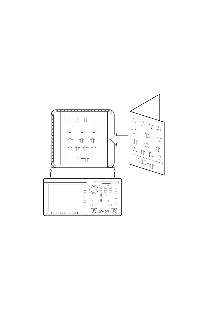
Using the CTS 710 Reference
The Reference presents an overview of the CTS 710 menu structure,
front-panel buttons, examples of alarm responses, and a glossary. To
store the Reference for easy viewing, fold the card to display the
desired page and slide the card behind the window located on the
inside of the top flap of the pouch (see Figure i).
Figure i: Placing the Reference for Easy Viewing
CTS 710 SONET T est Set User Manual
xxiii
Page 28

Preface
Contacting Tektronix
Product
Support
Service
Support
For other
information
To write us T ektronix, Inc.
For application-oriented questions about a T ektronix
measurement product, call toll free in North
America:
1-800-TEK-WIDE (1-800-835-9433 ext. 2400)
6:00 a.m. – 5:00 p.m. Pacific time
Or contact us by e-mail:
tm_app_supp@tek.com
For product support outside of North America,
contact your local T ektronix distributor or sales
office.
Contact your local T ektronix distributor or sales
office. Or visit our web site for a listing of
worldwide service locations.
http://www .tek.com
In North America:
1-800-TEK-WIDE (1-800-835-9433)
An operator will direct your call.
P.O. Box 1000
Wilsonville, OR 97070-1000
xxiv
CTS 710 SONET T est Set User Manual
Page 29

Getting Started Getting Started
Page 30

Page 31

Getting Started
This section provides a description of the CTS 710, a list of standard
and optional accessories, and explains how to operate the CTS 710
for the first time.
Product Description
The Tektronix CTS 710 SONET Test Set is a rugged, portable test set
designed for installing and maintaining telecommunications
networks. The CTS 710 is a SONET analyzer that combines bit error
rate test capabilities with overhead testing, payload mapping, and
demapping in one unit. The CTS 710 features the following
capabilities:
H STS-1, STS-3, OC-1, OC-3, OC-12, DS1, and DS3 transmit and
receive
H Optical interface available at 1310 nm and 1550 nm
H Bit Error Rate testing
H BIP error monitoring and analysis
H Payload mapping and demapping
H Tributary Add/Drop/Test
H Pointer generation, including sequences, and analysis
H Alarm generation and analysis
H DS1/DS3 error monitoring and analysis
H DS1 Demultiplex from direct-input DS3 or a DS3 embedded in a
SONET rate signal
H Performance monitoring
APS testing
H
H DCC and user channel access
H Programmable via IEEE 488.2 and RS-232
CTS 710 SONET Test Set User Manual
1–1
Page 32

Getting Started
The CTS 710 meets the needs of the craftsperson and the network
engineer. The CTS 710 meets the requirements of those working in
network installation and maintenance by providing the capability to
perform:
H Network integrity testing
H In-service performance monitoring
H Stimulus and response testing
H Stress testing
H Overhead testing
Accessories
Some accessories are included with the CTS 710 SONET T est Set. If
you wish to purchase optional accessories or additional standard
accessories, see a T ektronix products catalog or contact your local
T ektronix field representative.
1–2
Standard Accessories
H CTS 710 SONET Test Set User Manual, Tektronix part number
070-8852-XX
H CTS 710 SONET Test Set Reference, Tektronix part number
070-9336-XX
H Instrument Front Cover, Tektronix part number 200-3232-XX
H 75 W loopback cable, Tektronix part number 012-1338-XX
H Pouch, Tektronix part number 016-1266-XX
Optional Accessories
H CTS 710 SONET Test Set Programmer Manual (Tektronix part
number 070-8924-XX)
H CTS 710 SONET Test Set & CTS 750 SDH Test Set Reference,
Programming commands (T ektronix part number 070-8854-XX)
CTS 710 SONET T est Set User Manual
Page 33

H CTS 710 SONET Test Set & CTS 750 SDH Test Set Service
Manual (Tektronix part number 070-8853-XX)
H Hard Transit Case, Tektronix part number 016-1157-XX
H Soft Carrying Bag, Tektronix part number 016-1 158-XX
H K212 Portable Instrument Cart
H Optical Connector Kit, Tektronix part number 020-1885-XX
First Time Operation
This section describes how to set up the CTS 710 for the first time.
Installing the Accessory Pouch
The CTS 710 ships with an accessory pouch that mounts on top of
the instrument. The pouch is not installed at the factory. To install
the accessory pouch:
1. Place the CTS 710 on a table or work bench with the front facing
toward you.
Getting Started
2. Center the pouch plate and insert the rear edge of the plate in the
space between the cabinet top and the rear panel trim (see part A
of Figure 1–1).
3. Move the pouch sideways as necessary to line up the key slots in
the pouch plate with the keys on the rear panel (the plate is
centered when it is aligned) and push the plate all the way in (see
part B of Figure 1–1).
4. While keeping the pouch plate pushed under the rear panel trim,
reach under the pouch plate and carefully remove the backing
from the Velcro strip to expose the adhesive on the Velcro strip.
The Velcro should remain attached to the pouch plate.
5. Grasp the pouch plate assembly with both hands near the front of
the assembly.
CTS 710 SONET T est Set User Manual
1–3
Page 34

Getting Started
Rear Panel Trim Gap
Pouch
Plate
Rear
Panel
Trim
Key Slots Under
Rear Panel Trim
Pouch Plate
A. Push the pouch plate into the rear panel trim gap.
Velcro Strip
(Top View)
1–4
B. Center the pouch plate to align with key slot under the rear panel trim.
Figure 1–1: Installing the Accessory Pouch
CTS 710 SONET T est Set User Manual
Page 35

Getting Started
CAUTION. In the next step, use only enough force to clear the front
panel trim with the plate front edge. Excessive force will cause a
permanent bow in the plate.
6. Push back on the pouch plate and press down with the heels of
your hands to bow the plate enough to slide the front of the plate
into the space between the cabinet top and the front panel trim
(see Figure 1–2).
7. Move the front of the pouch as needed to line up the slots in the
plate with the keys on the front panel.
8. Release the pressure on the plate to allow it to return to its normal
flat shape.
9. Press down firmly to secure the Velcro strip to the top of the
cabinet top.
Velcro Strip
Figure 1–2: Inserting the Pouch Under the Front Panel Trim
CAUTION. Do not use the D-ring (see Figure 1–3) on the pouch plate
to lift the CTS 710. Using the D-ring to lift the CTS 710 can pull the
accessory pouch off the CTS 710, resulting in damage to the
CTS 710.
CTS 710 SONET T est Set User Manual
1–5
Page 36

Getting Started
DO NOT LIFT
Instrument
With D-Ring
1–6
Figure 1–3: Location of the D-Ring on the Accessory Pouch
CTS 710 SONET T est Set User Manual
Page 37
Getting Started
Setting Up the CTS 710
Before you use the CTS 710, ensure that it is properly set up and
powered on.
To properly set up the CTS 710, do the following:
1. Be sure that the environment in which you will operate the
CTS 710 is within instrument specifications. Specifications for
temperature, relative humidity, altitude, vibrations, and emissions
are included in Appendix D.
2. Leave space around the CTS 710 for cooling. Verify that the air
intake and exhaust holes on the sides of the cabinet (where the
fan operates) are free of any airflow obstructions. Leave at least
5 cm (2 in) free on each side.
WARNING. To avoid electrical shock, be sure that the power cord is
disconnected before checking the fuse.
3. Check the fuse to be sure it is the proper type and rating (see
Figure 1–4). The CTS 710 works with one of two fuses,
depending on the AC supply. Each fuse requires its own cap (see
T able 1–1). The CTS 710 is shipped with the UL-approved fuse
installed.
CTS 710 SONET T est Set User Manual
1–7
Page 38

Getting Started
Power
Connector
Ground
Fuse
Figure 1–4: Rear-Panel Controls and Connectors Used in Setup
Table 1–1: Fuse and Fuse Cap Part Numbers
Fuse
0.25 in 1.25 in
(UL 198.6, 3AG): 5 A
FAST, 250 V
5 mm 20 mm
(IEC 127): 4 A, 250 V
Fuse Tektronix
Part Number
159-0014-XX 200-2264-XX
159-0255-XX 200-2265-XX
Fuse Cap Tektronix
Part Number
Principal
Power Switch
1–8
CTS 710 SONET T est Set User Manual
Page 39

Getting Started
4. Check that you have the proper electrical connections. The
CTS 710 power requirements are listed in T able 1–2.
Table 1–2: Power Requirements
Voltage Range Frequency Range Maximum Power
90–132 V 48–62 Hz 250 W
180–250 V 48–62 Hz 250 W
5. Connect the proper power cord from the rear-panel power
connector (see Figure 1–4) to the power system.
Turning On the CTS 710
To properly turn on the CTS 710:
1. Check that the rear-panel principal power switch is on. The
principal power switch controls all AC power to the instrument.
2. If the CTS 710 is not turned on (the screen is blank), press the
front-panel ON/STBY (On/Standby) button to turn it on (see
Figure 1–5).
The ON/STBY button controls power to most instrument circuits.
Power continues to go to certain parts even when this switch is
set to STBY.
CTS 710 SONET T est Set User Manual
1–9
Page 40

Getting Started
ON/STBY
Button
Figure 1–5: ON/STBY Button
1–10
The CTS 710 performs an internal self test each time it is turned on.
When turned on, it displays a screen that states whether or not it
passed the self test. (If the self test passes, the status display screen is
removed after a few seconds.)
3. Check the self-test results.
If the self test fails, contact your local T ektronix Service Center for
assistance.
Turning Off the CTS 710
Press the ON/STBY button to turn off the CTS 710.
Once the CTS 710 is in use, it is typical to leave the principal power
switch on and use the ON/STBY button as the power switch. If the
CTS 710 is frequently moved, use the principal power switch to turn
the CTS 710 on and off.
CTS 710 SONET T est Set User Manual
Page 41

Operating Basics Operating Basics
Page 42

Page 43

Functional Overview
This section describes how to use and navigate through the basic
functions of the CTS 710, including:
H Controls, indicators, and connectors
H Elements of the display
H Menu structure
H On-line help
H Connecting signals
H Parameter selection and editing
H Disk drive operation
CTS 710 SONET Test Set User Manual
2–1
Page 44

Functional Overview
Front-Panel Controls, Indicators, and Connectors
Figures 2–1 and 2–2 identify the controls, indicators, and connectors
located on the front panel of the CTS 710 SONET T est Set.
These buttons assign the displayed choice to the
selected parameter or execute the selected action.
ON/STBY Switch
(the principal
power switch is on
the rear panel)
These buttons select the
pages of the current menu.
Figure 2–1: Controls Located Around the Display
2–2
CTS 710 SONET T est Set User Manual
Page 45

The knob is
primarily used
to highlight
parameters
within pages.
These buttons
select one of
the five
menus.
LASER IN
USE Indicator
Disk Drive
Functional Overview
Each of these buttons
perform a specific function.
DS1
Connectors
(optional)
Status Lights
DS3
Connectors
(optional)
Clear History
Button
Optical
Connector
Electrical
Connectors
Optical
Connector
Figure 2–2: Front-Panel Controls, Indicators, and Connectors
CTS 710 SONET T est Set User Manual
2–3
Page 46
GA
Functional Overview
GA
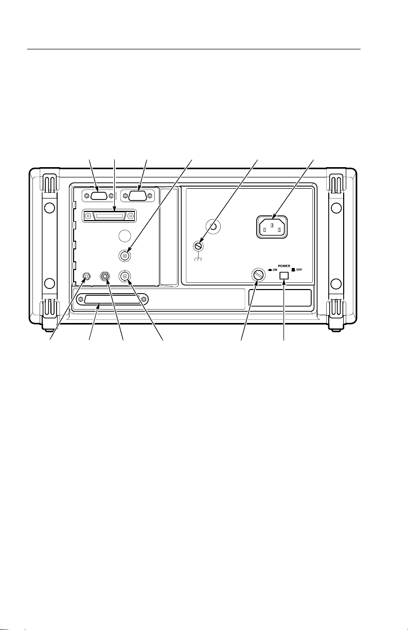
Rear-Panel Controls and Connectors
Calibration
Signal
Output
V
Video
Output
Overhead
Add/Drop
Port
GPIB
Port
1.544 Mb/s
BITS
Timing
Reference
Input
RS-232
Port
(Connector
External Clock
Input (Optional)
Not Used)
Figure 2–3: Rear-Panel Controls and Connectors
Fuse
Ground
Power
Connector
Principal
Power
Switch
Front-Panel Status Lights
The status lights make it easy to quickly determine the condition of
the received signal. There are three types of front-panel status lights.
H Green status lights. Green lights indicate whether a signal is
present and whether the CTS 710 has locked onto the signal.
H Red status lights. When a red status light is on, it means that the
indicated event is occurring. When the red light is off, no event is
occurring.
2–4
CTS 710 SONET T est Set User Manual
Page 47

Functional Overview
H Y ellow history lights. Once an event has been detected, a yellow
history light is turned on. The yellow history light shows that the
associated event occurred at some time in the past. Yellow history
lights remain on until you reset the event history by pressing the
CLEAR HISTORY button, starting a new test, or changing the
Receive Rate.
Yellow history lights
indicate an event has
occurred.
Red lights indicate an
event is occurring
now.
Green lights
indicate the
condition is true.
CLEAR HISTORY
button clears
history of events.
Figure 2–4: Status Lights (With Option 22 Installed)
CTS 710 SONET T est Set User Manual
2–5
Page 48

Functional Overview
Reading the Display
There are several major areas that make up the CTS 710 display (see
Figure 2–5).
This area displays the contents of the different
pages of each menu. Some pages display control
parameters; some pages display test results.
The menu name appears
here; the menu name is
always visible.
Status message
area. This area
is always visible.
Icons
Signal
Status
Indicators
Pages of
the Menu
Pressing one of these buttons selects the
page identified above the button.
Figure 2–5: Major Areas of the Display
2–6
Usually these
items are the
values that can
be assigned to
the selected
parameter.
CTS 710 SONET T est Set User Manual
Page 49

Functional Overview
Figure 2–6 provides a guide to specific areas of the display.
Parameters
or options
controlled
from this
page
Selected
page is
highlighted
Pages are
identified by
page tabs.
Menu
Name
Test State
Indicator
Highlighted parameters can be
changed; dimmed parameters
cannot be changed under the
current setup.
Test
Progress
Indicator
Highlighted
Parameter
Pages of the
Menu
Received
Signal
Status
Indicator
Choices or actions
available for the
selected parameter
Transmitted
Signal Status
Indicator
“–more–” means
additional
choices are
available.
Figure 2–6: Specific Elements of the Display
T able 2–1 provides a list of icons that appear on the display. Icons
are used to identify information, indicate instrument status, and
clarify available actions.
CTS 710 SONET T est Set User Manual
2–7
Page 50

Functional Overview
Table 2–1: Icons that Appear in the Display
Icon
Meaning
Transmitted signal
Received signal
CTS 710 is in through mode
CTS 710 is in coupled mode
Use the knob
Not allowed
File stored on disk
2–8
File stored in memory
Message or warning identifier
Press the button to perform the indicated action
The CTS 710 is busy
CTS 710 SONET T est Set User Manual
Page 51

The Basic Menu Structure
The CTS 710 is controlled primarily through its menu system.
Though several controls are located on the front panel, such as
INSERT ERROR, most functions are controlled from one of the five
menus. Figure 2–7 shows the five menus.
Functional Overview
Figure 2–7: The Five Menus
What is a Menu?
A menu groups related functions together. For example, all settings
that affect the signal transmitted by the CTS 710 are located in the
TRANSMIT menu. Each menu is made up of pages. A page is
CTS 710 SONET T est Set User Manual
2–9
Page 52

Functional Overview
identified by a page tab located at the bottom of the display (see
Figure 2–8).
TEST
CONTROL
TRANSMIT
SETTINGS
RECEIVE
SETTINGS
TEST
SUMMARY
RECALL
INSTRUMENT
SETUPS
ERRORS
& ALARMS
SIGNAL
STATUS
MAIN
RESULTS
RECALL
PASS/FAIL
TESTS
POINTERS
& TIMING
TRANSPORT
OVERHEAD
ERROR
ANALYSIS
SAVE
INSTRUMENT
SETUPS
APS
COMMANDS
PATH
OVERHEAD
HISTORY
GRAPHS
SAVE
PASS/FAIL
TESTS
TRANSPORT
OVERHEAD
SAVE
RESULTS
PATH
OVERHEAD
RECALL
RESULTS
MISC
SETTINGS
PRINTER
SETUP
CONTROL
Figure 2–8: Menus and Pages
The CTS 710 always displays a menu. The name of the current menu
is shown near the top of the display. To change to another menu,
press a menu button on the front panel.
2–10
REMOTE
INSTR
CONFIG
SELF
TEST
CTS 710 SONET T est Set User Manual
Page 53

Functional Overview
NOTE. The only times pressing a menu button does not change menus
are when a dialog box is displayed or when you are entering a value
for a parameter. Y ou must first exit the dialog box or finish entering
the value before you can change menus.
A page usually provides control over a related group of instrument
functions or parameters. For example, the TRANSMIT SETTINGS
page in the TRANSMIT menu controls the rate, format, and active
channels of the signal transmitted by the CTS 710. However, some
pages display information rather than provide control over settings;
for example, the pages of the RESULTS menu display various test
results.
Selecting Menus
To display a menu, press the button on the front panel with the same
name (see Figure 2–9).
Figure 2–9: Menu Select Buttons
Selecting Pages
T o select a page within a menu, press the button beneath the page tab
located at the bottom of the display (see Figure 2–10).
CTS 710 SONET T est Set User Manual
2–11
Page 54

Functional Overview
Page Tab
Display the page by
pressing the button
below the page tab.
Figure 2–10: How to Display a Page
Displaying Help
T o display help, press the HELP front-panel button.
When the HELP dialog box appears, use the knob to select the topic
you wish to view (see Figure 2–11). After you select the topic to
view , select View Help to see the help screen.
2–12
CTS 710 SONET T est Set User Manual
Page 55

Functional Overview
Figure 2–11: Help Dialog Box
Once you press V iew Help, the help screen for that topic is
displayed. If a help topic covers more than one page, you can display
the next page by selecting Page Down. To display the previous page,
select Page Up.
To display help in a different language, select Change Language.
Then, to display help in French, select Francais. T o display help in
German, select Deutsch.
When you finish reading the help text, you can exit the help dialog
box by selecting EXIT. If you wish to read additional help topics,
select Help Menu to return to the main help screen.
Connecting Signals
T o connect signals to the CTS 710, use the electrical and optical
connectors located at the bottom and right side of the front panel.
For optical connections, the CTS 710 accepts both single mode and
multimode fiber. For electrical connections, the CTS 710 accepts
75 W coaxial cable with BNC connectors for SONET rates and DS3
signals. The CTS 710 accepts bantam connectors for DS1 signals.
CTS 710 SONET T est Set User Manual
2–13
Page 56

Functional Overview
Connecting Optical Signals
NOTE. The optical TRANSMIT output is produced by a Class 1 laser
device. The output from a Class 1 laser is safe to view without
special eye protection. However, because other optical signals in
your environment may exceed the Class 1 limits, we recommend eye
protection as a precaution.
T o connect optical signals to the CTS 710:
1. Unscrew the dustcap that covers the optical port on the CTS 710.
2. Remove the dustcap (if present) covering the connector on the
optical fiber.
3. Carefully insert the transmit end of the optical fiber into the
RECEIVE port on the CTS 710. Line up the key on the optical
fiber connector with the cutout on the optical port connector.
Make sure that the optical fiber connector is fully inserted into
the optical port.
2–14
4. Tighten the optical fiber connector so it does not accidentally
come loose during use.
5. Carefully insert the receive end of the optical fiber into the
TRANSMIT port on the CTS 710. Make sure that the optical
fiber connector is fully inserted into the optical port.
6. Tighten the optical fiber connector so it does not accidentally
come loose during use. Tighten the connectors only finger tight;
do not use a tool to tighten the connectors.
CAUTION. To prevent damage to the optical port connectors and to
keep them clean, always replace the dustcaps on the optical port
connectors when not using the optical ports.
CTS 710 SONET T est Set User Manual
Page 57

Connecting SONET Electrical Signals
T o connect SONET electrical signals to the CTS 710:
1. Connect the transmit end of the signal cable to the RECEIVE
connector on the CTS 710.
2. Connect the receive end of the signal cable to the TRANSMIT
connector on the CTS 710.
Connecting DS1/DS3 Electrical Signals
T o connect DS1/DS3 electrical signals to the CTS 710:
1. Connect the transmit end of the signal cable to the IN connector
for the appropriate rate on the CTS 710.
2. Connect the receive end of the signal cable to the OUT connector
for the appropriate rate on the CTS 710.
Initiating Autoscan
Functional Overview
Autoscan is a feature that automatically scans the received signal and
changes the CTS 710 receive settings to match the received signal.
Autoscan is the quickest way to set up the CTS 710 to view a signal.
T o initiate autoscan, press the AUTOSCAN front-panel button. For
detailed information on the AUTOSCAN function, see Checking
Signal Status on page 3–55.
Changing Parameters
Most of the menu pages in the CTS 710 contain parameters (or
settings) that you can change. The choices available for a parameter
appear in four ways (examples in parentheses):
H As a list (Test Pattern: PRBS 2^23–1, PRBS 2^20–1, ...)
H As a decimal number (Frequency Offset: 74.3 ppm)
H As a binary number (Z1 Byte: 10101111)
H As a text string (File Name: TEST_34)
CTS 710 SONET T est Set User Manual
2–15
Page 58
Functional Overview
Selecting Parameters
T o change a parameter, use the knob to highlight it. As you turn the
knob, the display highlight moves from parameter to parameter (see
Figure 2–12).
This is the selected parameter. It is
identified by the location of the highlight.
Turning the
knob moves
the highlight
to another
parameter.
2–16
Figure 2–12: Selecting a Parameter
The parameter values displayed in high-intensity text indicate
parameters that you can change. If a parameter is displayed in
dimmed text, it cannot be selected under the current setup.
Selecting from Lists
Most parameters have a set group of choices available. The choices
are presented as a list, located along the right side of the display.
Press the button next to the choice to assign that choice to the
highlighted parameter.
Sometimes parameters have more than five choices available. When
more than five choices are available, the bottom choice changes to
–more–. Selecting –more– displays additional choices. Each time
CTS 710 SONET T est Set User Manual
Page 59

Functional Overview
you press –more– the next list of choices is displayed. Below –more–
is a line that shows which list of choices is displayed. When the last
list of choices is displayed, pressing –more– displays the first list of
choices again (see Figure 2–13).
Pressing a button assigns
List of
Choices
the choice next to the button
to the highlighted parameter.
Figure 2–13: Selecting Choices From a List
Changing Decimal Numbers
Some parameters allow you to set a numeric value for them. For
these parameters, preset choices are always provided to save you
time. However, if the preset choices are not appropriate for your
needs, you can set specific values by selecting the USER DEFINED
choice (see Figure 2–14).
CTS 710 SONET T est Set User Manual
Selecting –more–
displays additional
choices.
2–17
Page 60

Functional Overview
Figure 2–14: Selecting USER DEFINED
After you select USER DEFINED, the buttons at the right side of the
display are reassigned, as shown in Figure 2–15.
Selecting USER
DEFINED allows you to
enter a numeric value.
2–18
CTS 710 SONET T est Set User Manual
Page 61
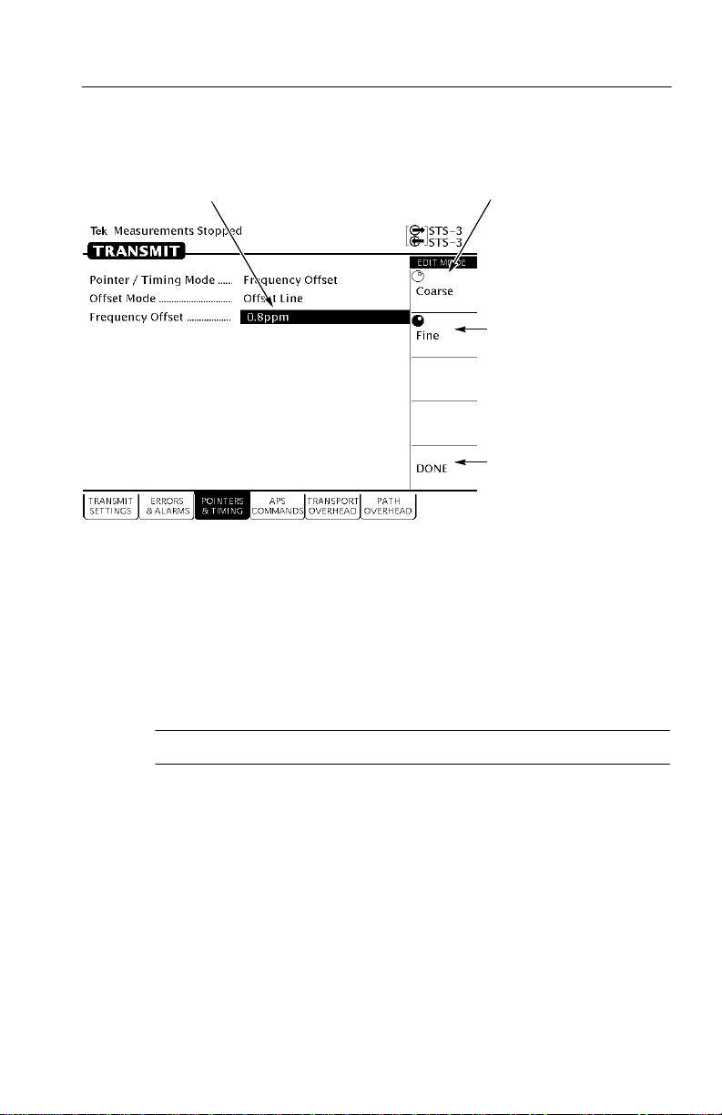
Functional Overview
Turning the knob
changes this value.
Figure 2–15: Entering a Numeric Value
After you press USER DEFINED, the CTS 710 enters edit mode. In
edit mode, you change the value of the highlighted parameter by
turning the knob. When you have set the parameter to the desired
value, select DONE to enter the value and exit edit mode.
Selecting this choice allows the knob
to make large changes quickly.
Selecting this
choice allows the
knob to make
small changes.
Y ou must select
DONE to exit
the edit mode.
NOTE. The new value does not take effect until DONE is selected.
When in edit mode, the knob can work in several ways. As shown in
Figure 2–15, the knob can be assigned to make either coarse or fine
adjustments to the highlighted parameter. For other parameters, the
knob is assigned to change different elements of the selected
parameter. For example, when setting a test time, rather than making
coarse or fine adjustments, the knob is assigned to change days,
hours, minutes, or seconds.
The knob icon is displayed in solid form to indicate which function it
is currently assigned to. The knob icon is displayed in outline form
next to other possible choices.
CTS 710 SONET T est Set User Manual
2–19
Page 62

Functional Overview
Changing Binary Numbers
There are two kinds of binary numbers that can be changed in the
CTS 710: payload patterns and overhead bytes. As with other
numerical values, you can select preset values or enter specific
values by selecting Edit Byte.
T o change a byte:
1. Select the byte with the knob (see Figure 2–16).
2. Change the byte by selecting one of the preset choices at the right
side of the display or to enter a different bit pattern, select EDIT
BYTE. This places the CTS 710 into edit mode.
The highlighted
byte can be
quickly set to
these choices by
pressing the
button next to the
desired choice.
Select the byte to edit
by using the knob.
Figure 2–16: Selecting a Byte for Editing
When in edit mode, the choices along the right side of the display
change (see Figure 2–17). The highlight now applies to a single
bit.
2–20
Select EDIT BYTE to change
the bits within the byte.
CTS 710 SONET T est Set User Manual
Page 63
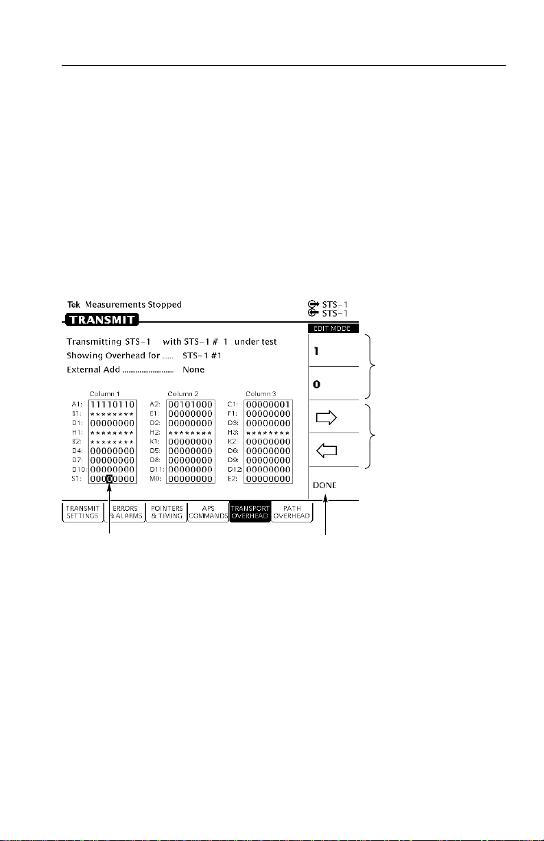
Functional Overview
3. To change the value of the highlighted bit, select either 1 or 0.
Each time you select 1 or 0, the highlighted bit is changed and
the highlight moves to the next bit.
4. To select a different bit for editing, select either the right or left
arrow to move the highlight. When the desired bit is highlighted,
select either 1 or 0.
5. When you are finished editing the byte, select DONE. This enters
the changes to the byte and exits edit mode.
Change the value
of the bit by
selecting one of
these choices.
Change the
highlighted bit by
selecting one of
these choices.
Select the bit to edit by
using the knob.
Select DONE when you are
Figure 2–17: Editing a Byte
Entering Text
Several parameters, such as file names, operator prompts, and path
trace messages, consist of text strings. You can set text strings to
preset choices or enter your own text string. When you highlight a
text parameter using the knob, the choices at the right side of the
display change to present predefined text strings (if appropriate) and
the option to edit the text string (see Figure 2–18).
CTS 710 SONET T est Set User Manual
finished editing.
2–21
Page 64

Functional Overview
Select the text string to edit by
using the knob.
Figure 2–18: Selecting a T ext String for Editing
Select EDIT TEXT to
edit the specified
text string.
2–22
To edit a text string:
1. Select the text string by turning the knob until the desired text
string is highlighted (see Figure 2–18).
2. Select EDIT TEXT . This places the CTS 710 into edit mode.
When in edit mode, the choices along the right side of the display
change (see Figure 2–19). In edit mode, the status line at the top
of the display is replaced with a line that displays the characters
available for placing into the text string. (Some characters
available for message text are not available for file names.)
3. T o change the highlighted character or enter a new one, select the
character to enter by turning the knob.
4. T o enter the selected character, select Enter <character>.
T o delete a character already entered, use the arrows to highlight
the character. Select Delete to delete the character.
CTS 710 SONET T est Set User Manual
Page 65

Functional Overview
5. When you are finished editing the text string, select DONE.
The characters available depend on
the text string being edited. The
characters used for file names are a
subset of the characters available for
message text.
The highlighted character is the
character that will be changed
when Enter ! is selected
Turning the knob selects the
character to be entered.
Select this choice to enter
the selected character.
Select this choice
to delete the
selected character.
Select either of
these choices to
move the
highlight within
the text string.
Select DONE when you
are finished editing text.
Figure 2–19: Editing a T ext String
Working with the Disk Drive
Use the disk drive in the CTS 710 to save instrument setups, pass/fail
tests, measurement results and measurement histories. The CTS 710
reads disks formatted in MS-DOS format. It reads only 1.44 MB
disks. The CTS 710 does not format disks. Files written to disk
consist of four types, as shown in T able 2–2.
CTS 710 SONET T est Set User Manual
2–23
Page 66

Functional Overview
Table 2–2: CTS 710 Disk File Types
File Type
Instrument Setups Complete description of instru-
Pass/Fail Tests Complete description of instru-
Measurement Results1An ASCII file listing the results
Measurement History1Binary file containing the
1
The CTS 710 creates two files (with extensions .RES and .HIS)
Description File Extension
.SET
ment settings
.TST
ment settings, operator
prompts, and Fail If conditions
.RES
of a test
.HIS
history of test results
when you save test results.
The CTS 710 displays only file names with the extensions shown in
T able 2–2. Disk files with any other extensions do not appear in file
name displays.
Reading Files on Disk
You can display disk file names in three places: the RECALL
INSTRUMENT SETUPS page and the RECALL PASS/FAIL TESTS
page of the TEST SETUPS menu, and the RECALL RESULTS page
of the RESULTS menu.
2–24
T o view instrument setups files on a disk:
1. Insert the disk into the disk drive.
2. Press the TEST SETUPS front-panel button to display the TEST
SETUPS menu.
3. Select the RECALL INSTRUMENT SETUPS page.
4. Select Disk to display the instrument setups on disk.
T o view pass/fail files on a disk:
1. Insert the disk into the disk drive.
CTS 710 SONET T est Set User Manual
Page 67

Functional Overview
2. Press the TEST SETUPS front-panel button to display the TEST
SETUPS menu.
3. Select the RECALL P ASS/FAIL TESTS page.
4. Select Disk to display the pass/fail tests on disk.
T o view test results files on a disk:
1. Insert the disk into the disk drive.
2. Press the RESULTS front-panel button to display the RESULTS
menu.
3. Select the RECALL RESUL TS page.
4. Select Disk to display the test results files on disk.
NOTE. Disk operations may take several seconds if there are many
files on the disk. The light on the front of the disk drive turns off
when the disk operation is complete.
CTS 710 SONET T est Set User Manual
2–25
Page 68

Functional Overview
2–26
CTS 710 SONET T est Set User Manual
Page 69

Tutorial
The tutorial acquaints you with the features of the CTS 710 by
having you run a test while you explore specific features of the
CTS 710. For full details on how to use the CTS 710, refer to
Reference.
The tutorial presents procedures in tables. Perform the procedure by
reading from left to right in the table (see example below). The word
none in a cell indicates that no action is required.
Press Menu
Button
Begin here with
Step 1
Some procedures require several iterations of highlighting parameters and selecting choices. Some procedures may require more than
one menu button or menu page selection as well.
Select Menu
Page
Step 2 Step 3 Step 4
Before Turning On the CTS 710
This tutorial describes how to perform a bit-error rate (BER) test on
an STS-1 signal. T o perform the tutorial, you need a 75 W coaxial
cable with BNC connectors on each end. This tutorial assumes you
have set up the CTS 710 as described in First Time Operation, on
page 1–3.
To set up your CTS 710 for the tutorial, perform these steps:
H Check that the CTS 710 is turned off. If it is on, you can put it in
standby mode by pressing the ON/STBY button.
Highlight
Parameter
Step 5 Step 6
Step 7 Step 8, CTS 710
Select Choice
instruction is
complete
CTS 710 SONET T est Set User Manual
2–27
Page 70

Tutorial
Connect the coaxial cable between the TRANSMIT and RECEIVE
BNC connectors on the front panel (see Figure 2–20).
CTS 710 SONET Test Set
75 W Coaxial Cable
Figure 2–20: Setup for the T utorial
Press the ON/STBY button to turn on the CTS 710.
The CTS 710 performs its power-on self test and then displays the
TRANSMIT menu.
Before proceeding with the tutorial, initialize the CTS 710 as
follows:
Press Menu
Button
TEST SETUPS RECALL
Select Menu
Page
INSTRUMENT
SETUPS
Setting Transmit Parameters
Before beginning the BER test, set the transmit and receive
parameters.
2–28
Highlight
Parameter
DEFAULT
FACTORY
SETTINGS
Select Choice
Recall Setup
CTS 710 SONET T est Set User Manual
Page 71
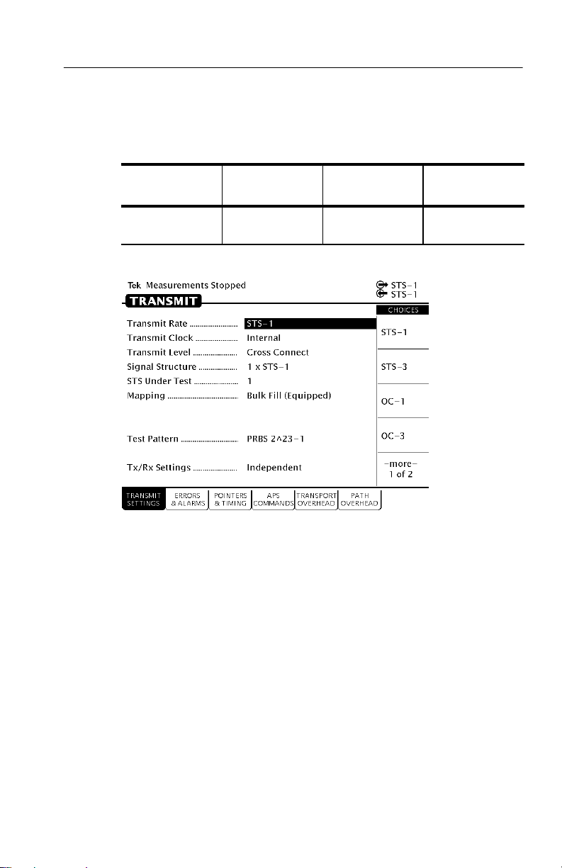
T o set the transmit and receive parameters:
Tutorial
Press Menu
Button
TRANSMIT TRANSMIT
Select Menu
Page
SETTINGS
Highlight
Parameter
Transmit Rate
(see Figure 2–21)
Select Choice
STS-3
Figure 2–21: The TRANSMIT SETTINGS Page of the TRANSMIT Menu
Note that as soon as you changed the transmit rate that the red
ERROR light on the front panel came on and the red LOS, LOF, and
LOP status lights came on (also, NO SIG appeared next to the
incoming-signal icon at the top of the display). The lights turned on
because you can set the transmit and receive settings independently
and right now the receive section is still set to STS-1. You will
change the receive rate later in this tutorial.
An STS-3 signal is made up of three STS-1 signals. The CTS 710
can test only one signal at a time; therefore, you must specify which
of the three signals that make up the STS-3 signal you wish to test.
This tutorial has you test the second signal. The signal to be tested is
identified on the STS Under T est line.
CTS 710 SONET T est Set User Manual
2–29
Page 72

Tutorial
To specify which signal, or STS, to test:
Press Menu
Button
T o set the mapping and the test pattern:
Press Menu
Button
Select Menu
Page
Select Menu
Page
Setting Receive Parameters
You can set receive parameters two ways. The first way is to set the
parameters individually: display the RECEIVE menu and set each
parameter manually on the RECEIVE SETTINGS page. The second
way is to couple the receive settings to the transmit settings. T o do
this, use the Tx/Rx Settings line on the TRANSMIT SETTINGS
page. (The Tx/Rx Settings line appears on both the TRANSMIT
SETTINGS page and the RECEIVE SETTINGS page. T o couple
transmit settings to the receive settings, you would use the Tx/Rx
Settings line on the RECEIVE SETTINGS page.)
Highlight
Parameter
STS Under Test 2
Highlight
Parameter
Mapping No Mapping
Test Pattern PRBS 2^20–1
Select Choice
Select Choice
(Equipped)
2–30
T o couple the receive settings to the transmit settings:
Press Menu
Button
TRANSMIT TRANSMIT
As soon as you select Coupled, the red error light turns off and the
icon in the status area changes to indicate the Tx/Rx Settings are
Select Menu
Page
SETTINGS
Highlight
Parameter
Tx/Rx Settings Coupled
CTS 710 SONET T est Set User Manual
Select Choice
Page 73

coupled. However, note that the yellow history light remains on as an
indication that an error has occurred.
Press CLEAR HISTORY to clear the error history light.
When the Tx/Rx Settings parameter is set to Coupled, all parameter
settings on the RECEIVE SETTINGS page transfer to the TRANSMIT SETTINGS page. Thereafter, any change to either page affects
both pages as long as Tx/Rx Settings is set to Coupled.
Setting the Test Time
Before beginning the BER test, you must specify the duration of the
test.
To set the duration of the test:
Tutorial
Press Menu
Button
TEST SETUPS
(see Figure 2–22)
Figure 2–22: The TEST CONTROL Page of the UTILITY Menu
Select Menu
Page
TEST CONTROL
Highlight
Parameter
Test Duration 15 min
Select Choice
CTS 710 SONET T est Set User Manual
2–31
Page 74
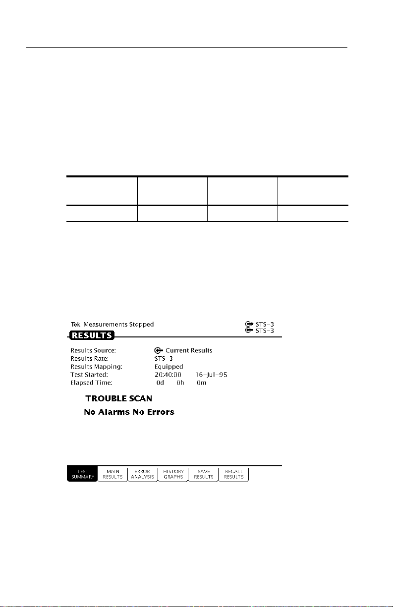
Tutorial
Where Test Results Are Displayed
Once you have set the transmit and receive parameters and the test
time, you can begin the test. However, before starting the test, look
at the RESULTS menu where the results of the test appear.
T o display the RESULTS menu:
Press Menu
Button
RESULTS none none none
The TEST SUMMARY page contains a summary of the current or
most recent test (see Figure 2–23). Just below the menu name is
information about the current or most recent test. If the test detected
no alarms or errors, the CTS 710 displays the message No Alarms
No Errors.
Select Menu
Page
Highlight
Parameter
Select Choice
2–32
Figure 2–23: The TEST SUMMARY Page of the RESULTS Menu
CTS 710 SONET Test Set User Manual
Page 75

Tutorial
The RESULTS menu contains four pages on which results are
displayed: TEST SUMMARY, MAIN RESULTS, ERROR
ANALYSIS, and HISTORY GRAPHS. Select MAIN RESULTS to
see one way test results are displayed (see Figure 2–24).
Figure 2–24: The MAIN RESUL TS Page of the RESULTS Menu
The MAIN RESULTS page contains a listing of the different errors
that can occur. Since you have not started your test yet, the values
are those of the last test run. T o continue with the test setup, select
TEST SUMMARY.
Begin the Test
Note at the top of the display the message Measurements Stopped.
When you start the test, this message will change. T o start the test,
press the front-panel START/STOP button.
Once a test starts, the display changes in two ways. First, the
message Running appears at the top of the display (see Figure 2–25).
This message line is always visible so you know that a test is
running, even if a page is displayed that doesn’t contain any
information about tests. Second, the test status indicator appears.
CTS 710 SONET Test Set User Manual
2–33
Page 76

Tutorial
There are two elements to the test status indicator. The text above the
bar graph indicates how long the test has been running. The text lists
the days, hours, minutes, and seconds the test has been running. The
bar graph indicates what percentage of the test is complete (except
when the test duration is set to continuous).
Figure 2–25: The Message Line and T est Status Indicator
Inserting Errors
Now that the test is running, you will insert some errors and see how
the CTS 710 responds. T o set the error insertion parameters, first
display the ERRORS & ALARMS page as follows:
Press Menu
Button
TRANSMIT ERRORS &
2–34
Select Menu
Page
ALARMS
(see Figure 2–26)
CTS 710 SONET Test Set User Manual
Highlight
Parameter
none none
Select Choice
Page 77
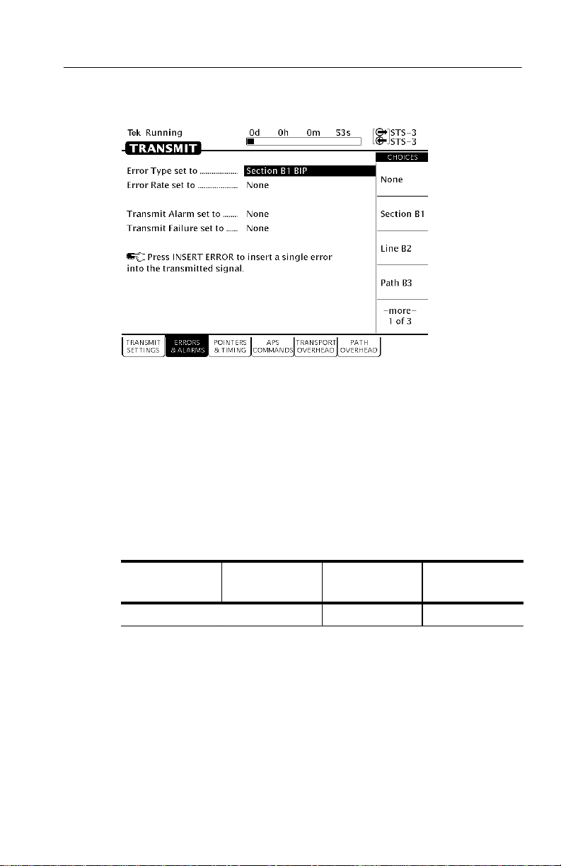
Tutorial
Figure 2–26: The ERRORS & ALARMS Page of the TRANSMIT Menu
There are two ways to insert errors into the transmitted signal. You
can insert errors one at a time or you can set a rate at which the
CTS 710 inserts errors automatically. Before inserting errors, you
must specify the type of error to be inserted. You specify the type of
error to be inserted with the Error type set to parameter.
To set the type of error to insert:
Press Menu
Button
Select Menu
Page
The rate at which errors are inserted is specified on the Error rate set
to line. An error rate of None specifies that no errors are inserted
unless the INSERT ERROR button is pressed. Any error rate other
CTS 710 SONET Test Set User Manual
Highlight
Parameter
Error type set to Path B3 BIP
Select Choice
2–35
Page 78

Tutorial
than None results in a continuous stream of errors being inserted into
the transmitted signal.
To insert a single error, press INSERT ERROR.
When you press the INSERT ERROR button the red ERROR light
flashes.
T o insert a continuous stream of errors:
Press Menu
Button
Note that the red ERROR light now stays on all the time; errors are
being detected continually.
T o turn off the automatic error insertion:
Press Menu
Button
TRANSMIT ERRORS &
Now that errors are no longer being transmitted, the red ERROR
light has gone out, although the yellow history light is still on. T o
clear the error history, press CLEAR HIST ORY.
Adjusting Pointers
The CTS 710 enables you to adjust or move pointers. Note that
pointer movements are not necessarily errors. Pointer parameters are
set on the POINTERS & TIMING page of the TRANSMIT menu.
Select Menu
Page
Select Menu
Page
ALARMS
Highlight
Parameter
Error rate set to 1.0E-5
Highlight
Parameter
Error Rate set to None
Select Choice
Select Choice
2–36
CTS 710 SONET T est Set User Manual
Page 79

T o display the POINTERS & TIMING page:
Tutorial
Press Menu
Button
TRANSMIT POINTERS &
Select Menu
Page
TIMING
(see Figure 2–27)
Highlight
Parameter
none none
Select Choice
Figure 2–27: The POINTERS & TIMING Page of the TRANSMIT Menu
Before adjusting a pointer, you must decide what mode of pointer
movement to use. You can change a pointer by adjusting the pointer
directly or by using frequency offset. The default mode is Pointer
Movements, which allows you to adjust pointers directly.
T o specify how the pointer will be adjusted:
Press Menu
Button
Select Menu
Page
CTS 710 SONET T est Set User Manual
Highlight
Parameter
Pointer Control Single
Select Choice
2–37
Page 80

Tutorial
After selecting Single for pointer control, a message displays that
tells you how to adjust the pointer. Pointer movement alternates
between increment and decrement.
T o adjust a pointer, press the front-panel POINTER ACTION
button.
Each time you press POINTER ACTION, a pointer adjusts and the
POINTER ACTION light turns on. Also, a message appears at the
top of the display that describes the type of pointer movement that
occurs. On this page you can also adjust frequency offset which may
cause a network element to generate pointer movements.
T o see the pointer value changing:
Press Menu
Button
RESULTS MAIN RESULTS none Pointers
Select Menu
Page
Highlight
Parameter
Select Choice
Now press POINTER ACTION again.
T o adjust a pointer using frequency offset:
Press Menu
Button
TRANSMIT POINTERS &
Select Menu
Page
TIMING
Highlight
Parameter
Pointer / Timing
Mode
Select Choice
Frequency Offset
After selecting Frequency Offset, note that the available parameters
change. When in Frequency Offset mode, the only parameters that
can be set are Offset Mode and Frequency Offset.
T o change the frequency offset of the signal:
Press Menu
Button
Select Menu
Page
Highlight
Parameter
Frequency Offset Stress +4.6ppm
Select Choice
2–38
CTS 710 SONET Test Set User Manual
Page 81

If the preset choices do not match what you need, use USER
DEFINED to define an alternative.
To define a specific frequency offset:
Tutorial
Press Menu
Button
Select Menu
Page
Highlight
Parameter
Select Choice
USER DEFINED
When you select USER DEFINED, the knob is assigned to adjust the
frequency offset. Two choices are available in this mode: Coarse and
Fine (see Figure 2–28). Coarse adjusts the frequency offset by
10 ppm. Fine adjusts the frequency offset by 0.1 ppm. The larger the
value for frequency offset, the more often the pointer is adjusted.
Figure 2–28: Adjusting Frequency Offset Using the Knob
CTS 710 SONET Test Set User Manual
2–39
Page 82

Tutorial
Use the knob to change the value of Frequency Offset; select any
value you wish. When you are finished selecting a frequency offset:
Press Menu
Button
T o turn off frequency offset:
Press Menu
Button
TRANSMIT POINTERS &
Selecting Default 0ppm sets the Frequency Offset back to 0 ppm.
Select Menu
Page
Select Menu
Page
TIMING
Viewing Transport Overhead
The CTS 710 allows you to view the transport overhead for the
transmitted or received signal. T o view the transport overhead for the
transmitted signal:
Press Menu
Button
TRANSMIT TRANSPORT
Select Menu
Page
OVERHEAD
Highlight
Parameter
Highlight
Parameter
Frequency Offset
Highlight
Parameter
none none
Select Choice
DONE
Select Choice
Default 0ppm
Select Choice
2–40
The first line of text under the menu name describes the signal being
received and the STS under test (see Figure 2–29).
CTS 710 SONET T est Set User Manual
Page 83
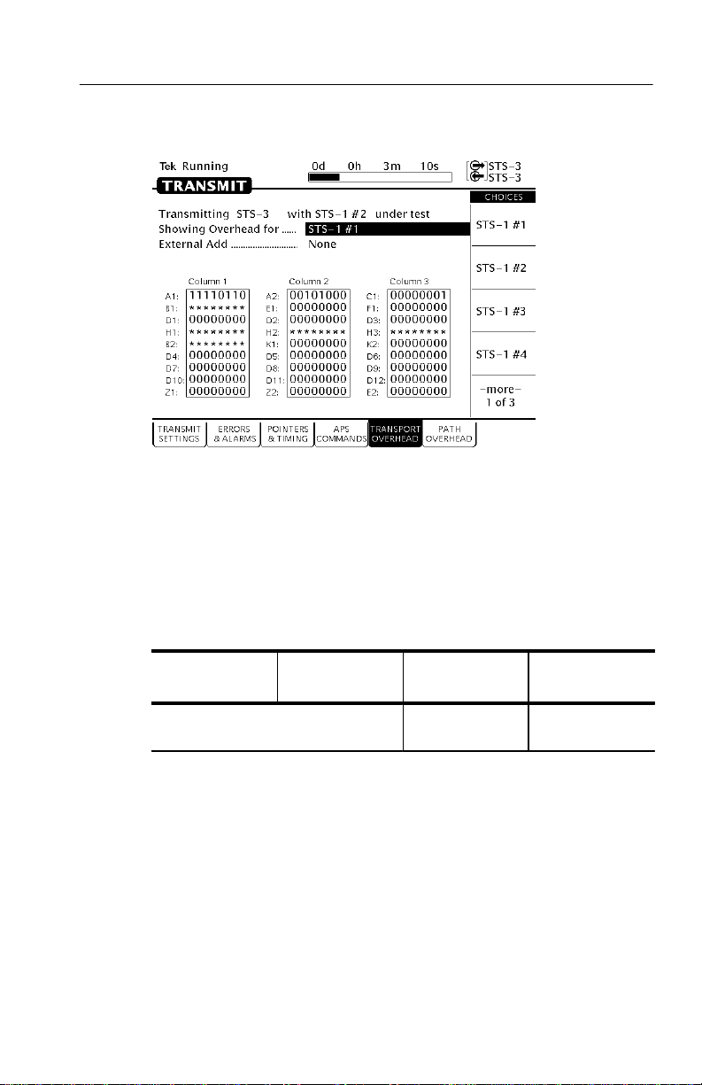
Tutorial
Figure 2–29: The TRANSPORT OVERHEAD Page of the TRANSMIT
Menu
The Showing Overhead for parameter identifies which columns of
the transport overhead are displayed. T o display the overhead for
other SPEs within the signal, select the appropriate choice.
Press Menu
Button
Select Menu
Page
Editing the Transport Overhead
Except for certain reserved bytes, you can edit the bytes of the
transport overhead of the transmitted signal. Reserved bytes are
identified by asterisks (*) in the byte content area of the displayed
column.
CTS 710 SONET T est Set User Manual
Highlight
Parameter
Showing
Overhead for
Select Choice
STS–1 #1
2–41
Page 84

Tutorial
To edit a byte of the transport overhead:
Press Menu
Button
Select Menu
Page
Highlight
Parameter
S1 byte
Select Choice
EDIT BYTE
Once you have selected EDIT BYTE, the CTS 710 enters the edit
mode (see Figure 2–30).
2–42
Figure 2–30: The Display in Edit Mode
To change the value of any bit within the byte, highlight the bit you
wish to change. T o change the value of the highlighted bit, select
either 1 or 0. After you assign a value to the highlighted bit, the
highlight moves to the next bit to be edited.
Edit the S1 byte to read 10101010.
Select DONE when you have finished editing the byte.
You can assign preset values to the highlighted byte. For example,
rather than editing each bit of the byte as you just did, you could also
CTS 710 SONET T est Set User Manual
Page 85

have selected Set to 10101010. T o see that the CTS 710 is now
receiving the new value of the S1 byte:
Tutorial
Press Menu
Button
RECEIVE TRANSPORT
Verify that the transport overhead for STS–1 #1 is displayed. If it is
not:
Press Menu
Button
Look at the value of the S1 byte. You will see that it is 10101010, as
previously set.
Viewing Test Results
The test has been running for several minutes and errors have been
transmitted. T o see the test results, you must display the RESULTS
menu. T o display the RESULTS menu:
Select Menu
Page
OVERHEAD
Select Menu
Page
Highlight
Parameter
none none
Highlight
Parameter
Showing
Overhead for
Select Choice
Select Choice
STS–1 #1
Press Menu
Button
RESULTS TEST SUMMARY none none
The TEST SUMMARY page identifies the most common errors that
the CTS 710 has detected. You will see a line that identifies the
worst error rate detected and may find listings for other types of
errors (see Figure 2–31).
CTS 710 SONET T est Set User Manual
Select Menu
Page
Highlight
Parameter
Select Choice
2–43
Page 86

Tutorial
Figure 2–31: The TEST SUMMARY Page of the RESULTS Menu
The MAIN RESULTS page displays all the errors that have been
detected. It also displays the error ratio and the number of errored
seconds that have been logged (see Figure 2–32).
2–44
T o display the MAIN RESULTS page:
Press Menu
Button
Select Menu
Page
MAIN RESULTS none none
Highlight
Parameter
CTS 710 SONET Test Set User Manual
Select Choice
Page 87
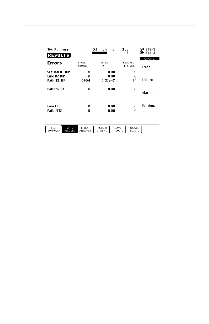
Tutorial
Figure 2–32: The MAIN RESUL TS Page of the RESULTS Menu
This completes the tutorial. For detailed information on CTS 710
capabilities, refer to Reference, starting on page 3–1.
CTS 710 SONET Test Set User Manual
2–45
Page 88

Tutorial
2–46
CTS 710 SONET T est Set User Manual
Page 89

Reference Reference
Page 90

Page 91

Basic Test Procedures
This section gives examples of how to set up and use the
CTS 710 SONET Test Set for several common telecommunication
network applications:
H Network continuity checking
H Transmission signal quality testing
H Fault tolerance testing
H Performance monitoring
Setting Up the CTS 710
This section presents setup instructions for the CTS 710 in tables.
Perform the steps reading from left to right in the table (see example
below). The word none in a cell indicates that no action is required.
Press Menu
Button
Begin here with
Step 1
Menu buttons are located on the instrument front panel. Select menu
pages with the buttons below the display. Use the knob to highlight a
parameter; then use the buttons at the right to select a choice. Many
setups require several iterations of highlighting parameters and
selecting choices. Some setups may require more than one menu
button or menu page selection as well.
The first step in each application setup initializes the CTS 710 to a
known state.
CTS 710 SONET T est Set User Manual
Select Menu
Page
Step 2 Step 3 Step 4
Highlight
Parameter
Step 5 Step 6
Step 7 Step 8, CTS 710
Select Choice
Setup is complete
3–1
Page 92

Basic Test Procedures
Network Continuity Checking
With the AUTOSCAN feature of the CTS 710, it is easy to make a
quick continuity check. The continuity check verifies that a SONET
network element (NE), or portion of the network, is correctly set up
and provisioned and that the signal passes through intact. In this
example, the CTS 710 transmits an STS-3 signal into an NE. Then
the CTS 710 receives the output from the NE and verifies that all
three SPEs, including their payload patterns, are intact.
1. Connect the CTS 710 to the NE as shown in Figure 3–1.
CTS 710 SONET Test Set
3–2
All Signals are
STS-3
One or More SONET NEs
Figure 3–1: Setup to Check Network Continuity
CTS 710 SONET T est Set User Manual
Page 93

2. Set up the CTS 710 as follows:
Basic Test Procedures
Press Menu
Button
TEST SETUPS RECALL
TRANSMIT TRANSMIT
Select Menu
Page
INSTRUMENT
SETUPS
SETTINGS
Highlight
Parameter
DEFAULT
FACTORY
SETTINGS
Transmit Rate STS-3
Select Choice
Recall Setup
3. Press the AUTOSCAN button. The receiver locks onto the output
from the NE, displays the signal structure, and shows information
about the content of STS #1.
4. T o analyze the payload pattern, select Show Payload. The
CTS 710 detects a PRBS of length 223–1.
5. Check the J1 Path Trace for any message.
6. Check the front-panel status lights to verify that there are no
errors, alarms, or failures.
7. Select EXIT to leave the AUTOSCAN dialog box.
8. To check STS #2, change the CTS 710 setup to:
Press Menu
Button
TRANSMIT TRANSMIT
Select Menu
Page
SETTINGS
Highlight
Parameter
STS Under Test 2
Select Choice
9. Press the AUTOSCAN button.
10.Use the knob to select STS #2.
11. Repeat steps 4 through 7 of this procedure to verify the integrity
of STS #2.
12.Repeat steps 8 through 11 for the remaining STSs in the SONET
signal.
CTS 710 SONET T est Set User Manual
3–3
Page 94

Basic Test Procedures
Transmission Signal Quality Testing
Measuring Bit Error Rate
The bit error rate (BER) test is one of the best ways to measure the
quality of a SONET transmission link. You can use the CTS 710 to
make a BER test on a two-way link that is connected in a loop-back
configuration. If this is a test you perform often, save it as a pass/fail
test for easy recall.
1. Connect the CTS 710 to a network as shown in Figure 3–2.
CTS 710 SONET Test Set
All Signals are
STS-1
One or More SONET NEs
Figure 3–2: Setup to Check a Transmission Link
3–4
CTS 710 SONET T est Set User Manual
NE
Page 95

2. Set up the CTS 710 as follows:
Basic Test Procedures
Press Menu
Button
TEST SETUPS RECALL
TRANSMIT TRANSMIT
TEST SETUPS TEST CONTROL Test Duration 15 Minutes
RESULTS MAIN RESULTS none Errors
Select Menu
Page
INSTRUMENT
SETUPS
SETTINGS
Highlight
Parameter
DEFAULT
FACTORY
SETTINGS
Transmit Rate STS-1
Mapping Bulk Fill
Tx/Rx Settings Coupled
Select Choice
Recall Setup
No Mapping
(Equipped)
3. Press the START/STOP button.
4. While the test is running, the CTS 710 counts errors and errored
seconds and then calculates the error ratio for each error type.
5. After 15 minutes have elapsed, the test stops automatically and
the measured results are held on the MAIN RESULTS page until
another test is started.
6. When the test is complete, you can store the test results to disk or
print out a hardcopy. To save the test results to disk, you must
enter a name for the disk file as follows:
Press Menu
Button
RESULTS SAVE RESULTS Name EDIT NAME
Select Menu
Page
7. Enter an eight-character name for the file.
CTS 710 SONET T est Set User Manual
Highlight
Parameter
Select Choice
3–5
Page 96

Basic Test Procedures
8. If you wish, you can also enter a description of the test results by
highlighting Description and selecting EDIT TEXT .
9. Save the test results to disk as follows:
Press Menu
Button
Select Menu
Page
Highlight
Parameter
Save to Disk Save Current
Select Choice
Testing Mapping and Demapping
To test that a DS1 signal is correctly mapped into a SONET signal,
you would use a Bit Error Rate test. However, testing mapping/demapping requires a different test setup than that described on
page 3–4.
1. Connect the CTS 710 to an Add/Drop Multiplexer (ADM) as
shown in Figure 3–3.
CTS 710 SONET Test Set
DS1
STS–1
Figure 3–3: Setup to Test Mapping and Demapping
3–6
CTS 710 SONET T est Set User Manual
DS1 Add/Drop
Multiplexer
Page 97

2. Set up the CTS 710 as follows:
Basic Test Procedures
Press Menu
Button
TEST SETUPS RECALL
TRANSMIT TRANSMIT
RECEIVE RECEIVE
TEST SETUPS TEST CONTROL Test Duration 15 Minutes
RESULTS MAIN RESULTS none Errors
Select Menu
Page
INSTRUMENT
SETUPS
SETTINGS
SETTINGS
Highlight
Parameter
DEFAULT
FACTORY
SETTINGS
Transmit Rate DS1
Receive Rate STS-1
Mapping VT1.5 Async
VT Under Test Set to match how
Payload DS1 Unframed
Select Choice
Recall Setup
the NE is
provisioned
3. Press the START/STOP button.
While the test is running, the CTS 710 counts errors and errored
seconds and then calculates the error ratio for each error type.
After 15 minutes have elapsed, the test stops automatically and the
measured results are held on the MAIN RESULTS page until another
test is started.
CTS 710 SONET T est Set User Manual
3–7
Page 98

Basic T est Procedures
4. When the test is complete, you can store the test results to disk or
print out a hardcopy. To save the test results to disk, you must
enter a name for the disk file as follows:
Press Menu
Button
RESULTS SAVE RESULTS Name EDIT NAME
5. Enter an eight-character name for the file.
6. If you wish, you can also enter a description of the test results by
highlighting Description and selecting EDIT TEXT .
7. Save the test results to disk as follows:
Press Menu
Button
Select Menu
Page
Select Menu
Page
Fault Tolerance Checking
Fault tolerance testing (sometimes called stimulus/response testing or
stress testing) is used to ensure that a network responds correctly to
various fault conditions. Though there are many additional fault
conditions you can test with the CTS 710, this section covers three
common examples:
Highlight
Parameter
Highlight
Parameter
Save to Disk Save Current
Select Choice
Select Choice
3–8
H Response to errors and alarms
H Response to pointer movements
H Response to line frequency offset
Response to Errors and Alarms
This example uses two CTS 710s to simultaneously check the
upstream and downstream responses to an error or alarm condition.
You can use a single CTS 710 to do the same thing by alternately
CTS 710 SONET T est Set User Manual
Page 99

Basic T est Procedures
connecting the upstream and downstream signals to the RECEIVE
input.
T able 3–1 shows the responses expected from Line Terminating
Equipment (LTE), such as an STS-3/STS-1 multiplexer, when
presented with three possible error and alarm conditions.
Table 3–1: LTE Responses to Errors and Alarms
Transmitted Error or
Alarm
Section B1 Error Line FEBE none
LINE AIS LINE FERF PATH AIS
PATH FERF none PATH FERF
Expected Upstream
Response
Expected Downstream Response
1. Connect two CTS 710s to an LTE as shown in Figure 3–4.
CTS 710 SONET Test Set CTS 710 SONET Test Set
All Signals are
STS-1
Downstream
Upstream
LTE
Figure 3–4: Setup to Check Error and Alarm Response
CTS 710 SONET T est Set User Manual
3–9
Page 100

Basic Test Procedures
2. To check the LTE response to a Section B1 error, set up the
upstream CTS 710 as follows:
Press Menu
Button
TEST SETUPS RECALL
TRANSMIT TRANSMIT
TRANSMIT ERRORS &
RESULTS MAIN RESULTS none Errors
Select Menu
Page
INSTRUMENT
SETUPS
SETTINGS
ALARMS
Highlight
Parameter
DEFAULT
FACTORY
SETTINGS
Transmit Rate STS-1
Tx/Rx Settings Coupled
Error Type Section B1 BIP
Error Rate set to 1.0E–5
Select Choice
Recall Setup
3–10
CTS 710 SONET T est Set User Manual
 Loading...