

Page 1

Instructions
CT-1/CT-2
Current Transformer
070-7957-01
Page 2

Copyright © T ektronix, Inc. All rights reserved.
T ektronix products are covered by U.S. and foreign patents, issued and pending. Information in this publication supercedes
that in all previously published material. Specifications and price change privileges reserved.
Printed in the U.S.A.
T ektronix, Inc., P.O. Box 1000, Wilsonville, OR 97070–1000
TEKTRONIX and TEK are registered trademarks of T ektronix, Inc.
Page 3

WARRANTY
T ektronix warrants that the products that it manufactures and sells will be free from defects in materials and
workmanship for a period of one (1) year from the date of shipment. If a product proves defective during this
warranty period, T ektronix, at its option, either will repair the defective product without charge for parts and labor,
or will provide a replacement in exchange for the defective product.
In order to obtain service under this warranty, Customer must notify Tektronix of the defect before the expiration
of the warranty period and make suitable arrangements for the performance of service. T ektronix will provide
such service at Customer’s site without charge during the warranty period, if the service is performed within the
normal on-site service area. T ektronix will provide on-site service outside the normal on-site service area only
upon prior agreement and subject to payment of all travel expenses by Customer. When or where on-site service is
not available, Customer shall be responsible for packaging and shipping the defective product to the service center
designated by T ektronix, with shipping charges prepaid. Tektronix shall pay for the return of the product to
Customer if the shipment is to a location within the country in which the T ektronix service center is located.
Customer shall be responsible for paying all shipping charges, duties, taxes, and any other charges for products
returned to any other locations.
This warranty shall not apply to any defect, failure or damage caused by improper use or improper or inadequate
maintenance and care. T ektronix shall not be obligated to furnish service under this warranty a) to repair damage
resulting from attempts by personnel other than T ektronix representatives to install, repair or service the product;
b) to repair damage resulting from improper use or connection to incompatible equipment; c) to repair any
damage or malfunction caused by the use of non-T ektronix supplies; or d) to service a product that has been
modified or integrated with other products when the effect of such modification or integration increases the time
or difficulty of servicing the product.
THIS WARRANTY IS GIVEN BY TEKTRONIX IN LIEU OF ANY OTHER W ARRANTIES, EXPRESS
OR IMPLIED. TEKTRONIX AND ITS VENDORS DISCLAIM ANY IMPLIED WARRANTIES OF
MERCHANTABILITY OR FITNESS FOR A PARTICULAR PURPOSE. TEKTRONIX’
RESPONSIBILITY TO REPAIR OR REPLACE DEFECTIVE PRODUCTS IS THE SOLE AND
EXCLUSIVE REMEDY PROVIDED TO THE CUST OMER FOR BREACH OF THIS WARRANTY.
TEKTRONIX AND ITS VENDORS WILL NOT BE LIABLE FOR ANY INDIRECT , SPECIAL,
INCIDENTAL, OR CONSEQUENTIAL DAMAGES IRRESPECTIVE OF WHETHER TEKTRONIX OR
THE VENDOR HAS ADVANCE NOTICE OF THE POSSIBILITY OF SUCH DAMAGES.
Page 4

Page 5
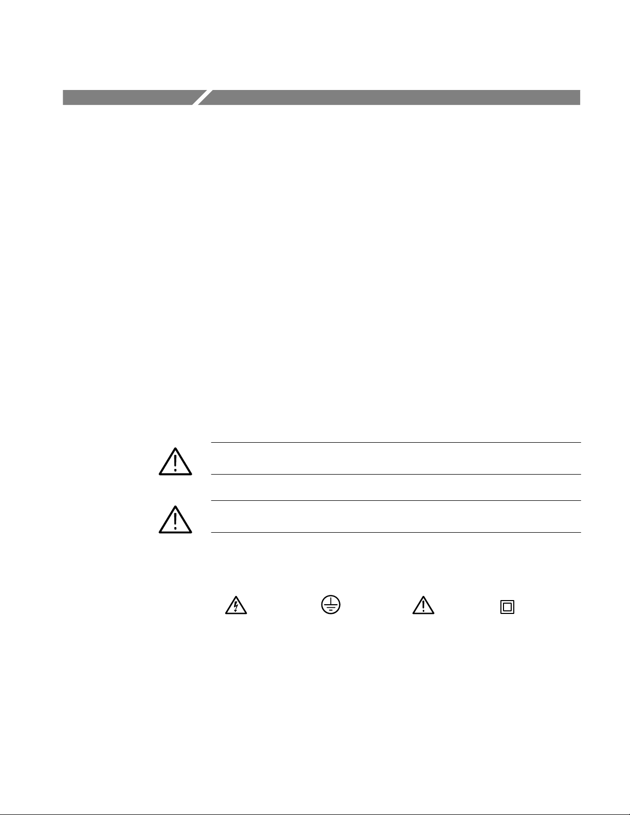
General Safety Summary
Review the following safety precautions to avoid injury and prevent damage to
this product or any products connected to it. To avoid potential hazards, use this
product only as specified.
To Avoid Fire or
Personal Injury
Symbols and Terms
Observe All Terminal Ratings. To avoid fire or shock hazard, observe all ratings
and markings on the product. Consult the product manual for further ratings
information before making connections to the product.
Do Not Operate With Suspected Failures. If you suspect there is damage to this
product, have it inspected by qualified service personnel.
Ground the Product. To avoid electric shock, the mounting stud must be
connected to earth ground.
Do Not Operate in Wet/Damp Conditions.
Do Not Operate in an Explosive Atmosphere.
Keep Product Surfaces Clean and Dry .
T erms in this Manual. These terms may appear in this manual:
WARNING. Warning statements identify conditions or practices that could result
in injury or loss of life.
CAUTION. Caution statements identify conditions or practices that could result in
damage to this product or other property.
CT-1/CT-2 Current Transformer
Symbols on the Product. The following symbols may appear on the product:
WARNING
High Voltage
Protective Ground
(Earth) T erminal
CAUTION
Refer to Manual
Double
Insulated
i
Page 6

General Safety Summary
ii
CT-1/CT-2 Current Transformer
Page 7

Introduction
The CT-1 and CT-2 are high-frequency, bidirectional current probes. The CT-1 is
a 1 GHz current probe and the CT-2 is a 200 MHz current probe. Each current
probe comes with a P6041 probe cable to allow you to connect directly to an
oscilloscope to make measurements.
Earth ground
mounting stud
Figure 1: CT-1 current probe
The CT-1 and CT-2 are available as separately purchased units (Option 09). See
the Replaceable Parts List at the end of this manual for ordering information.
This manual provides information on four subjects:
H Description
H Operation
H Specifications
H Replaceable Parts List
P6041 Probe
connection
CT-1/CT-2 Current Transformer
1
Page 8

Description
The CT-1 (1 GHz) and CT-2 (200 MHz) are current probes designed for either
permanent or temporary installation in the device-under-test (DUT). These
probes are particularly useful for measuring high-frequency currents in solid state
circuitry with minimum circuit loading. Due to bidirectional compatibility, the
CT-1 and CT-2 can be used to inject a signal or as an interstage transformer.
The probes inductively measure current through a conductor and develop a
voltage proportional to the current. For each mA of input current, they output
5 mv (1 mv for CT-2) of signal when properly terminated. Since the CT-1 and
the CT-2 are dynamic current probes (non-DC), the presence of DC current
affects their performance. Figures 2 and 3 show the influence of DC current on
frequency response.
0.5 A
100%
90%
0 A
DC
DC
1 A
DC
80%
70%
Frequency (Hz)
This response was obtained with the + side of the CT-1 facing
the signal source (preferred connection above 800 MHz)
Figure 2: CT-1 frequency response vs. DC current
1 G10 M100 k 100 M1 M10 k
2
CT-1/CT-2 Current Transformer
Page 9

100%
90%
80%
70%
60%
0 A
DC
0.5 A
DC
1 A
Description
DC
100 k 1 M10 k1 k
Frequency (Hz)
This response was obtained with the + side of the CT-2 facing the
signal source (preferred connection)
10 M 100 M
Figure 3: CT-2 frequency response vs. DC current
The CT-1 and CT-2 consist of a current transformer and a flexible probe
cable that attaches between the transformer and the oscilloscope. In
addition, the CT-1 and CT-2 have an internal termination resistor that
reduces reflections that allows the transformer to be disconnected from the
probe cable and left in the circuit. Figure 4 shows a simplified circuit of the
CT-1 and CT-2.
Input circuit
50 W
CT-1/CT-2 Current Transformer
Figure 4: CT-1 and CT-2 simplified circuit
3
Page 10

Specifications
Table 1 lists the electrical characteristics of the CT-1 and CT-2 Transformers
when they are connected to the P6041 Probe cable. The environmental and
physical characteristics follow Tables 1 and 2.
T able 1: Electrical characteristics
Specification CT-1 with P6041 Probe CT-2 with P6041 Probe
Sensitivity
(see Figures 2 and 3)
Pulse Response Rise time: < 0.35 ns, 10% to 90%
L/R time constant Approximately 5 ms Approximately 125 ms
Insertion Impedance 50 W termination: 1 W shunted by approxi-
Frequency Response 25 kHz to 1 GHz 1.2 kHz to 200 MHz
Turns Ratio 1:5 1:25
Capacitive Loading #14 bare wire: typically 1.5 pF
Maximum Bare Wire Voltage
(uninsulated)
Signal Delay (with P6041 Probe
Cable)
5 mV/mA, ±3% into a 50 W load 1 mV/mA, ±3% into a 50 W load
Rise time: < 0.5 ns, 10% to 90%
Aberrations: < 5% as seen by a 1 GHz system
mately 5 mH
Unterminated: 2 W shunted by approximately
5 mH
#20 bare wire: typically 0.6 pF
175 V
1000 V (DC + peak AC) <3.25% duty factor
Approximately 2.8 ns measured from 50%
points on leading edge of the current step and
output voltage
RMS
CAT I
Aberrations: + 4%, –8% as seen by a
200 MHz system
50 W termination: 0.04 W shunted by
approximately 5 mH
Unterminated: 0.08 W shunted by approximately 5 mH
#16 bare wire: typically 1.8 pF
#22 bare wire: typically 0.7 pF
175 V
1000 V (DC + peak AC) <3.25% duty factor
Approximately 5.8 ns measured from 50%
points on leading edge of the current step and
output voltage
RMS
CAT I
CT-1 T ransformer only: 0.4 ns
Effect of Direct Current
(see Figures 6 and 7)
Amp Second Rating 1 amp msec
Pulse Current Rating 12 amps 36 amps
RMS Current Rating 0.5 amperes maximum 2.5 amperes maximum
Output Connector Amphenol Sub-Minax #27-3 Amphenol Sub-Minax #27-3
Approximately 0.3 ADC increases decay by a
factor of 2
When this product is exceeded, the core
saturates and the CT-1 output drops to zero
4
CT-2 T ransformer only: 0.3 ns
Approximately 0.3 ADC increases decay by a
factor of 2
50 amp msec
When this product is exceeded, the core
saturates and the CT-2 output drops to zero
CT-1/CT-2 Current Transformer
Page 11

T able 2: General specifications (CT-1 and CT-2)
Environmental
Meets all Class IV instrument specifications
Operating Temperature 0_ C to +55_ C
Nonoperating T emperature –62_ C to +82_ C
Mechanical
Dimensions
Specifications
Hole size:
CT-1 1.78 mm (0.070 in.)
CT-2 1.32 mm (0.052 in.)
6-32
mounting
stud
Connector
38.6 mm
(1.52 in.)
15 mm
(0.59 in.)
10.3 mm
(0.406 in.)
P6041 Probe cable length 106.68 mm (42 in.)
Weight 15 gm (0.525 oz.) without P6041
47 gm (1.655 oz.) with P6041
Certifications and compliances
EC Declaration of Conformity – Low
Voltage
Compliance was demonstrated to the following specification as listed in the Official Journal of
the European Communities:
Low Voltage Directive 73/23/EEC, as amended by 93/68/EEC
EN 61010-1:1993
Safety requirements for electrical equipment for measurement, control, and laboratory use
Installation Category Descriptions Terminals on this product may have different installation category designations. The installation
categories are:
CA T III Distribution-level mains (usually permanently connected). Equipment at this level is
typically in a fixed industrial location
CA T II Local-level mains (wall sockets). Equipment at this level includes appliances, portable
tools, and similar products. Equipment is usually cord-connected
CA T I Secondary (signal level) or battery operated circuits of electronic equipment
CT-1/CT-2 Current Transformer
5
Page 12

Operation
This section describes how to install the CT-1 or CT-2, discusses low-frequency
probing, and provides information on safety and product care.
Installing the CT-1 or CT-2
The CT-1 or CT-2 transformers can be attached to the chassis or circuit board to
measure current in transistors, diodes, or other components. Any number of
transformers can be used.
When observing the output of a CT-1 or CT-2 transformer, ensure it is terminated
into 50 W. If the oscilloscope input is not 50 W, use a suitable matching
terminator (see recommended accessories in the Replaceable Parts List).
Figure 5 shows the output of the CT-1 compared with the input pulse from a
250 ps fast-rise pulse generator and the output of the CT-2 as seen by a 100 MHz
oscilloscope system.
If the CT-1 or CT-2 is connected so that the positive (+) label side faces the
signal source, the input current and output voltage will be in phase. This is the
preferred connection. For pulses with a risetime slower than 1 ns, the CT-1 or
CT-2 may be connected in either polarity.
Ground and the voltage ratings do not apply when installed on a fully insulated
conductor. The 175 V rating is based on long term applications that may degrade
the insulation. The voltage on bare signal wire must be limited to the 175 V
and the 1000 V DC + peak AC ratings.
Input current Output voltage
2 ns/div100 mV/div
CT-1 output waveform
Figure 5: CT-1 and CT-2 output waveform
100 mV/div
CT-2 output waveform
Output voltage
RMS
20 ns/div
6
CT-1/CT-2 Current Transformer
Page 13

Low Frequency Response
The low-frequency response of the current transformer is proportional to the
inductance of the transformer windings. A DC component in the current being
measured tends to reduce this inductance. Figures 2 and 3 show this effect in the
frequency domain.
This effect is also seen in the time domain. Figure 6 shows that the pulse tilt is
increased in the presence of significant DC current. The DC current required to
increase the tilt by a factor of two is about 0.3 A. Pulse currents that start at zero
and remain unidirectional have a DC component that the user should consider.
When droop is present at low frequencies, the apparent overall peak-to-peak
height from top to bottom is not the true current. The height of a flat-top pulse
still can be measured accurately by observing the transition edge of the pulse. In
Figure 7, the 50 mA pulse is faithfully reproduced at the high-to-low transition at
the center of the screen.
Pulse width, tilt, and the lower 3 dB frequency are related by the formula:
Operation
Percent tilt = 200π Tp f
1
Where:
Tp = pulse width
f1 = lower 3 dB frequency
20 ms/div10 mA/div
Input
current
Output
voltage
0 A
DC
0.3 A
1 A
DC
DC
Figure 6: CT-1 decay characteristics referenced to front corner
CT-1/CT-2 Current Transformer
7
Page 14

Operation
Probe Handling
0 A
0.4 A
Input
current
DC
DC
5 ms/div10 mA/div
Output
voltage
0.4 A
DC
0 A
DC
Figure 7: CT-2 decay characteristics referenced to transition
Additional consideration needs to be given to the amp second rating of the
transformer. The product of the pulse current and the pulse duration should be
less than the amp second rating to keep the transformer core from saturating.
When saturation occurs, the output voltage falls to zero.
Only normal handling considerations are necessary with the CT-1 and CT-2
transformers. They are sealed units and are not designed to be disassembled. If
the transformer or cable is damaged, return it to Tektronix for replacement.
CAUTION. Dropping the CT-1 or CT-2 transformer may break the probe. Do not
pull or stretch the P6041 cable or place objects on the cable. This may damage
the probe cable.
8
CT-1/CT-2 Current Transformer
Page 15

Replaceable Parts List
This section contains a list of the replaceable parts for the CT-1 and CT-2. Use
this list to identify and order replacement parts.
Parts Ordering Information
Replacement parts are available through your local Tektronix field office or
representative.
Changes to Tektronix products are sometimes made to accommodate improved
components as they become available and to give you the benefit of the latest
improvements. Therefore, when ordering parts, it is important to include the
following information in your order:
H Part number
H Instrument type or model number
H Instrument serial number
H Instrument modification number, if applicable
If you order a part that has been replaced with a different or improved part, your
local Tektronix field office or representative will contact you concerning any
change in part number.
Change information, if any, is located at the rear of this manual.
Using the Replaceable Parts List
The tabular information in the Replaceable Parts List is arranged for quick
retrieval. Understanding the structure and features of the list will help you find
all of the information you need for ordering replacement parts. The following
table describes the content of each column in the parts list.
CT-1/CT-2 Current Transformer
9
Page 16

Replaceable Parts List
Parts list column descriptions
Column Column name Description
1 Figure & index number Items in this section are referenced by figure and index numbers to the exploded view
illustrations that follow.
2 Tektronix part number Use this part number when ordering replacement parts from Tektronix.
3 and 4 Serial number Column three indicates the serial number at which the part was first effective. Column four
indicates the serial number at which the part was discontinued. No entries indicates the part is
good for all serial numbers.
5 Qty This indicates the quantity of parts used.
6 Name & description An item name is separated from the description by a colon (:). Because of space limitations, an
item name may sometimes appear as incomplete. Use the U.S. Federal Catalog handbook
H6-1 for further item name identification.
7 Mfr. code This indicates the code of the actual manufacturer of the part.
8 Mfr. part number This indicates the actual manufacturer’s or vendor’s part number.
Abbreviations
Mfr. Code to Manufacturer
Cross Index
Abbreviations conform to American National Standard ANSI Y1.1–1972.
The table titled Manufacturers Cross Index shows codes, names, and addresses
of manufacturers or vendors of components listed in the parts list.
10
CT-1/CT-2 Current Transformer
Page 17

Replaceable Parts List
1
2 3
Recommended
accessories
Figure 8: CT-1 and CT-2 accessories
Replaceable parts list
Fig. &
index
number
8-1 CURRENT TRANSFORMER:CT-1 OR CT-2 WITH
8-2 1 P6041 80009 P6041
8-3 103–0028–00 1 ADAPTER,CONN:BNC,FEMALE TO
8-4 01 1–0049–01 1 TERMN,COAXIAL:50 OHM,2W,BNC 80009 011–0049–01
Tektronix
part number
070–7957–XX 1 MANUAL,TECH:CT1/CT2 PROBE,DP TK2548 PER TEK
Serial no.
effective
Serial no.
discont’d
Qty Name & description Mfr. code Mfr. part number
CT-1 OR CT -2
P6041
(OPION 09 W/O P6041)
24931 28A100–2
FEMALE,1.3 L,GOLD/NICKEL
DOCUMENTA TION
4
Manufacturers cross index
Mfr.
code
24931 BERG ELECTRONICS INC BERG ELECTRONICS RF/COAXIAL DIV
80009 TEKTRONIX INC 14150 SW KARL BRAUN DR
TK2548 XEROX CORPORATION 14181 SW MILLIKAN WA Y BEAVERT ON, OR 97005
Manufacturer Address City , state, zip code
FRANKLIN, IN 46131
2100 EARLYWOOD DR
PO BOX 547
BEAVERT ON, OR 97077–0001
PO BOX 500
CT-1/CT-2 Current Transformer
11
Page 18

Replaceable Parts List
12
CT-1/CT-2 Current Transformer
Page 19

Page 20

 Loading...