

Page 1

Instructions
CSA8UP and TDS8UP
Option CPU
TDS8000 and CSA8000 Series Instruments
CPU Upgrade Kit
071-1384-00
Warning
The servicing instructions are for use by qualified
personnel only. To avoid personal injury, do not
perform any servicing unless you are qualified to
do so. Refer to all safety summaries prior to
performing service.
www.tektronix.com
*P071138400*
071138400
Page 2

Copyright © Tektronix, Inc. All rights reserved.
Tektronix products are covered by U.S. and foreign patents, issued and pending. Information in this publication supercedes
that in all previously published material. Specifications and price change privileges reserved.
Tektronix, Inc., P.O. Box 500, Beaverton, OR 97077
TEKTRONIX and TEK are registered tradem arks of Tektronix, Inc.
Page 3

General Safety Summary
Review the following safety precautions to avoid injury and prevent damage to
this product or any products connected to it. To avoid potential hazards, use this
product only as specified.
Only qualified personnel should perform service procedures.
While using this product, you may need to access other parts of the system. Read
the General Safety Summary in other system manuals for warnings and cautions
related to operating the system.
ToAvoidFireor
Personal Injury
Use Proper Power Cord. Use only the power cord specified for this product and
certified for the country of use. Power cord needed only in the mainframe, not
modules.
Connect and Disconnect Properly. Do not connect or disconnect probes or test
leads while they are connected to a voltage source.
Ground the Product. The mainframe is grounded through the grounding
conductor of the power cord. To avoid electric shock, the grounding conductor
must be connected to earth ground. Before making connections to the input or
output terminals of the product, ensure that the product is properly grounded.
Ground the Product. The modules are indirectly grounded through the grounding
conductor of the mainframe power cord. To avoid electric shock, the grounding
conductor must be connected to earth ground. Before making connections to the
input or output terminals of the product, ensure that the product is properly
grounded.
Observe All Terminal Ratings. To avoid fire or shock hazard, observe all ratings
and markings on the product. Consult the product manual for further ratings
information before making connections to the product.
Do not apply a potential to any terminal, including the common terminal, that
exceeds the maximum rating of that terminal.
Do Not Operate Without Covers. Do not operate this product with covers or panels
removed.
Use Proper Fuse. Use only the fuse type and rating specified for this product.
Avoid Exposed Circuitry. Do not touch exposed connections and components
when power is present.
Wear Eye Protection. Wear eye protection if exposure to high-intensity rays or
laser radiation exists.
Do Not Operate With Suspected Failures. If you suspect there is damage to this
product, have it inspected by qualified service personnel.
CSA8UP and TDS8UP Option CPU Upgrade Kit
1
Page 4
General Safety Summary
Do Not Operate in Wet/Damp Conditions.
Do Not Operate in an Explosive Atmosphere.
Keep Product Surfaces Clean and Dry.
Provide Proper Ventilation. Refer to the manual’s installation instructions for
details on installing the product so it has proper ventilation.
Symbols and Terms
Terms in this Manual. These terms may appear in this manual:
WARNING. Warning statements identify conditions or practices that could result
in injury or loss of life.
CAUTION. Caution statements identify conditions or practices that could result in
damage to this product or other property.
Terms on the Product. These terms may appear on the product:
DANGER indicates an injury hazard immediately accessible as you read the
marking.
WARNING indicates an injury hazard not immediately accessible as you read the
marking.
CAUTION indicates a hazard to property including the product.
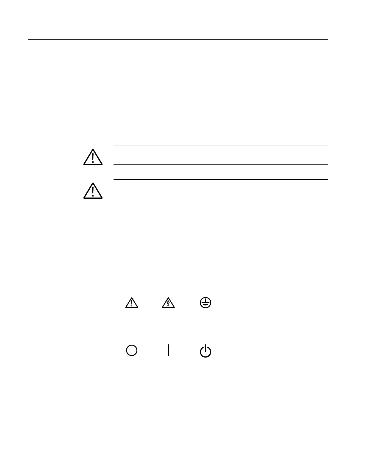
Symbols on the Product. The following symbols may appear on the product:
CAUTION
Refer to Manual
Mains Disconnected
OFF (Power)
WARNING
High Voltage
Mains Connected
ON (Power)
2
Protective Ground
(Earth) Terminal
Standby
CSA8UP and TDS8UP Option CPU Upgrade Kit
Page 5

Service Safety Summary
Only qualified personnel should perform service procedures. Read this Service
Safety Summary and the General Safety Summary before performing any service
procedures.
Do Not Service Alone. Do not perform internal service or adjustments of this
product unless another person capable of rendering first aid and resuscitation is
present.
Disconnect Power. To avoid electric shock, switch off the instrument power, then
disconnect the power cord from the mains power.
Use Care When Servicing With Power On. Dangerous voltages or currents may
exist in this product. Disconnect power, remove battery (if applicable), and
disconnect test leads before removing protective panels, soldering, or replacing
components.
To avoid electric shock, do not touch exposed connections.
CSA8UP and TDS8UP Option CPU Upgrade Kit
3
Page 6

Service Safety Summary
4
CSA8UP and TDS8UP Option CPU Upgrade Kit
Page 7
Kit Description
Products
Kit Parts List
This document supports upgrading the CPU board and microprocessor. To install
the upgrade, perform each of the following procedures in order.
Tektronix installation service (Option IF) is highly recommended for this
upgrade. If installation service is desired, please contact the service center in
your region to schedule installation.
This document supports Tektronix modification: ECO1092
CSA8000 Series All serial numbers
TDS8000 Series All serial numbers
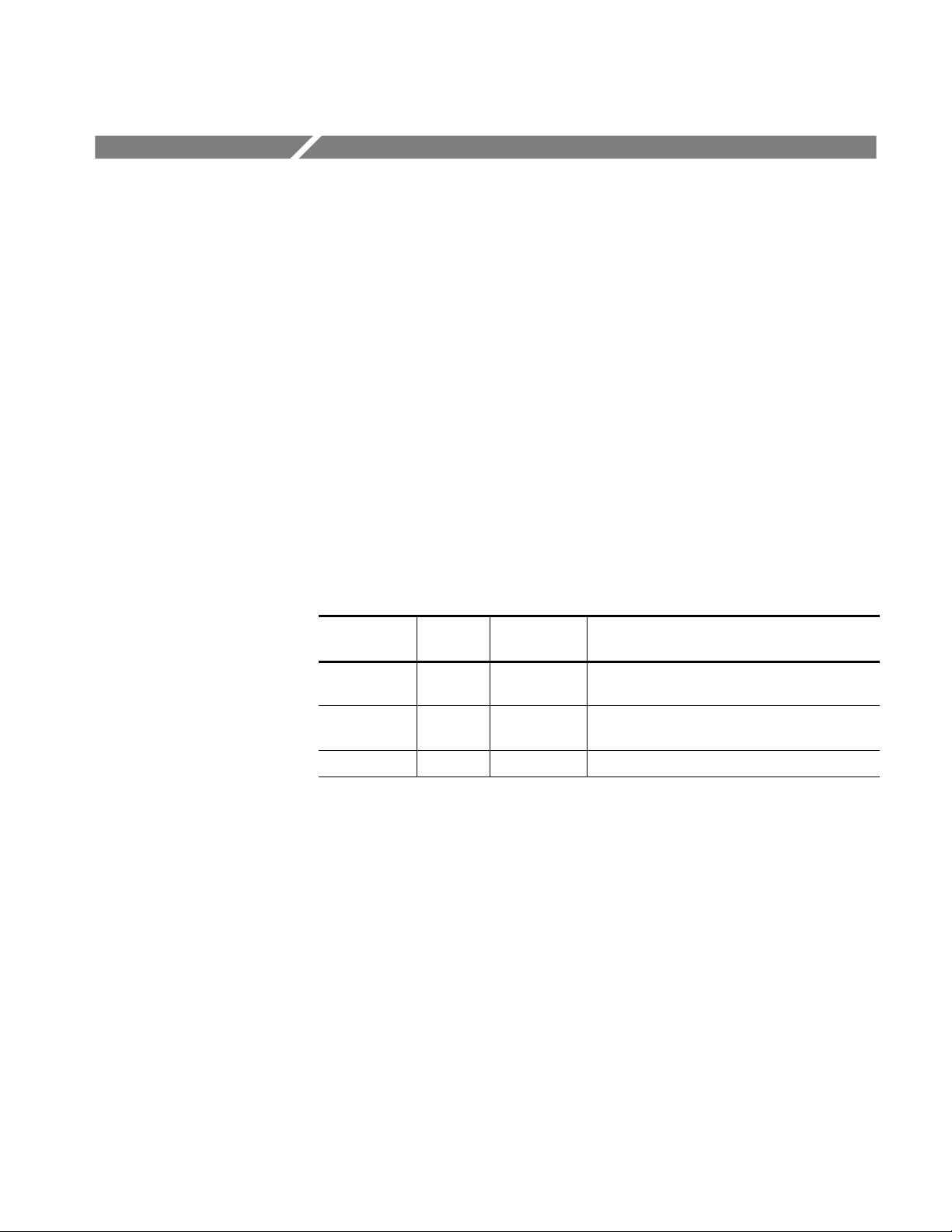
Circuit/figure
number
1 1ea 650--4603--XX COMPONENT KIT; MOTHERBOARD/
Quantity Part number Description
MICROPROCESSOR UPGRADE
1 1ea 407--4880--XX BRACKET; CD--ROM, REAR DRIVE BAY
CHASSIS, 0.035 CRS
1 1ea 071--1384--XX MANUAL, KIT INSTRUCTIONS
CSA8UP and TDS8UP Option CPU Upgrade Kit
5
Page 8

Kit Description
6
CSA8UP and TDS8UP Option CPU Upgrade Kit
Page 9

Installation Instructions
This section contains the procedures needed to install the CSA8UP or TDS8UP
Option CPU in the CSA8000 and TDS8000 S eries instruments.
These instructions are a service procedure and should be performed by qualified
service personnel. If you need further details for disassembling or reassembling
the product, refer to the TDS8000 and CSA8000 Series Service manual. Contact
your nearest Tektronix Service Center or Tektronix Factory Service for installation assistance.
CAUTION. To prevent static discharge damage, service the product only in a
static-free environment. Observe standard handling precautions for static-sensitive devices while installing this kit. Always wear a grounded wrist strap,
grounded foot strap, and static resistant apparel while installing this kit.
Preparation
WARNING. Before doing this or any other procedure in this manual, read the
Safety Summaries found at the beginning of these instructions.
This subsection contains the following items:
H Preparatory information that you need to properly do the procedures that
follow.
H A list of tools required.
H Procedures to disassembly the instrument and install the new NLX Board
assembly.
WARNING. Before doing any procedure in this subsection, disconnect the power
cord from the line voltage source. Failure to do so could cause serious injury or
death.
CSA8UP and TDS8UP Option CPU Upgrade Kit
7
Page 10

Installation Instructions
Equipment Required. Most modules in this instrument can be removed with a
screwdriver handle mounted with a size T-15, TorxR screwdriver tip. Use this
tool whenever a procedure step instructs you to remove or install a screw unless
a different size screwdriver is specified in that step.
Table 1: Tools required for module removal
Item
No.
1 Screwdriver handle Accepts TorxR-driver bits General Tool:
Name Description Part number
620-440
2 T-15 Torx tip Used for removing most the instru-
ment’s screws.
3 T-20 Torx tip Used for removing the handle
screws.
4
5 #0 Phillips screwdriver Screwdriver for removing small
1
/4inch flat-bladed screw-
driver
Screwdriver for unlocking side
panels.
phillips screws.
General Tool:
640-247
General Tool:
640-250
Standard tool
Standard tool
The following procedures are found here and are listed in order presented.
H Trim (all)
H Bottom cover
H Left and Right covers
8
CSA8UP and TDS8UP Option CPU Upgrade Kit
Page 11

Installation Instructions
Trim and Carrying Handle
1. Locate module to be removed: Locate the Trim to be removed. See Figure 1,
page 10.
2. Remove the top cover trim: Use Figure 1, page 10 as a guide.
a. Remove the accessory pouch; it snaps off.
b. Remove the four T-15 Torxdrive screws that secure the top cover trim to
the instrument. The T-15 Torxdrive screws also secure the snap studs to
the top cover.
c. Remove the top cover trim from the instrument.
3. Remove the front panel trim: Use Figure 1, page 10, as a guide.
a. Slide the flat end of a soldering aid (or flat screwdriver) into the side slot
on the trim ring to help detach the side snaps.
b. Swing the bottom of the ring upward and off the front panel.
4. Remove the acquisition trim: Use Figure 1, page 10 as a guide.
a. Remove the six T-15 Torxdrive screws that secure the acquisition trim to
the instrument.
b. Remove the knobs from the electrical and optical ejector levers. Grasp
the knobs with your fingers and pull straight out.
c. Remove the acquisition trim from the instrument.
5. Remove the carrying handle and the right/left side trim panels: Use
Figure 1, page 10 as a guide.
a. Remove the two T-20 Torxdrive screws that secure the handle to the
instrument. Remove the handle from the instrument.
CAUTION. Over-tightening the handle screws may cause the handle to break off
from the cabinet. When reinstalling the screws, use a torque wrench to tighten
the screws to 8--10 in.lb.
b. Slide the side trim panels towards the rear of the instrument allowing the
tabs to clear the cover openings, then pull out to remove the panels from
the instrument.
6. Reinstallation: Do in reverse steps 2 through 5 to reinstall the appropriate
trim.
CSA8UP and TDS8UP Option CPU Upgrade Kit
9
Page 12

Installation Instructions
Left side trim
T-15 Torxdrive
screw (3)
T-15 Torxdrive
screw (4)
Top cover trim
Right side trim
Front panel trim
Figure 1: Trim removal
Acquisition trim
T-15 Torxdrive screw (3)
Soldering aid
To remove the trim ring, slide the flat
end of a soldering aid into the side
slot on the trim ring. Press in, then lift
up to hook it underneath, then pry
up.
Carrying handle
T-20 Torxdrive
screw (2)
10
CSA8UP and TDS8UP Option CPU Upgrade Kit
Page 13

Installation Instructions
Bottom Cover
1. Locate the module to be removed: Locate the bottom cover. See Figure 2,
page 11.
2. Orient the instrument: Set the instrument so its top is down on the work
surface and its bottom is facing you.
3. Remove the bottom cover: Use Figure 2 on page 11 as a guide.
a. Remove the five T-15 Torxdrive screws that secure the bottom cover to
the instrument.
b. Remove the bottom cover from the instrument.
4. Reinstallation: Do in reverse steps a and b to reinstall the cabinet feet.
T-15 Torxdrive
screw (5)
Figure 2: Bottom cover removal
CSA8UP and TDS8UP Option CPU Upgrade Kit
Bottom cover
11
Page 14

Installation Instructions
Left and Right Covers
1. Locate the module to be removed: Locate the left and right covers. See
Figures 3 and 4, pages 13 and 14
2. Orient the instrument: Set the instrument so its rear is on the work surface
and the front of the instrument facing the technician.
NOTE. All mounting screw holes are indicated by a star etched around the
mounting hole.
3. Remove the left and right covers: UseFigures3and4onpages13and14as
a guide.
a. Remove the thirteen T-15 Torxdrive screws that secure the covers to the
top and both sides of the chassis.
b. Remove the nine T-15 Torxdrive screws that secure the covers to the
bottom of the chassis.
c. Pull the bottom-right cover down and slide to the right to remove from
the instrument. Pull the top-left cover upward and slide to the left to
remove from the instrument.
CAUTION. Take care not to bind or snag the covers on the instrument’s internal
cabling as you remove or install.
4. Reinstallation: Do in reverse steps a through c to reinstall the cabinet.
12
CSA8UP and TDS8UP Option CPU Upgrade Kit
Page 15

Installation Instructions
Left side cover
Right side cover
Figure 3: Cover removal
All left and right
cover mounting
holes are
indicated as
shown.
T-15 Torxdrive
screw (13)
CSA8UP and TDS8UP Option CPU Upgrade Kit
13
Page 16

Installation Instructions
Left side cover
14
Right side cover
T-15 Torxdrive
screw (9)
Figure 4: Cover removal
CSA8UP and TDS8UP Option CPU Upgrade Kit
Page 17

Installation Instructions
Remove NLX Board
Assembly
1. Locate the module: Locate the NLX board assembly. See Figure 5, page 16
2. Orient the instrument: Set the instrument so its bottom is down on the work
surface and its top panel is facing you.
3. Remove the NLX Board assembly: Use Figure 5 on page 16 as a guide.
a. Remove the five T-15 Torxdrive screws that secure NLX board assembly
to the inner chassis.
b. Remove the five T-15 Torxdrive screws that secure NLX board assembly
to the rear chassis.
NOTE. If you wish, you may remove the entire floppy disk drive assembly from
the front chassis to ease the removal and installation of the NLX board assembly.
Remove the two Torxdrive screws that secure the floppy disk drive assembly to
the front chassis. Lay the floppy disk drive assembly on top of the NLX board
assembly.
c. Grasp the front edge of the NLX board assembly and pull up on the
assembly to disconnect the Riser Adapter from the PC Processor board’s
edge connector.
CAUTION. If you are leaving the floppy disk drive installed, be careful not to
stress the floppy drive ribbon cable while removing the NLX board assembly.
d. Remove the NLX board assembly from the instrument and set it on top
of the instrument chassis.
e. Disconnect the floppy disk drive cable from the Riser Adapter board
(unless you’ve removed the floppy disk drive assembly from the front
chassis).
CSA8UP and TDS8UP Option CPU Upgrade Kit
15
Page 18

Installation Instructions
Floppy drive cable
Hard/CD drive bracket
(may appear different
on some instruments)
NLX board
assembly
Riser Adapter
board
Floppy drive
assembly
Processor board
edge connector
Figure 5: NLX assembly removal
4. Remove the Riser Adapter board: See Figure 6, page 17.
a. Remove the two T-15 Torxdrive screws that secure Riser Adapter board
to the NLX support bracket.
16
CSA8UP and TDS8UP Option CPU Upgrade Kit
Page 19

Installation Instructions
b. Disconnect the ribbon cables from the hard drive and CDROM drive.
(Disconnect the ribbon cable from the Floppy drive if you removed the
Floppy drive assembly.)
c. Grasp the Riser board and pull it straight out to disconnect J510 edge
card connector from the NLX board. Remove the Riser Adapter board
from the NLX board assembly.
NLX board
Riser Adapter
board
J230
J250
Two T-- 15
torxdrive screws
NLX support
Figure 6: Riser Adapter & NLX board removal
5. Remove the Hard/CD Drive assembly: See Figure 7, page 18.
a. Remove the two T-15 Torxdrive screws that secure CDROM drive
assembly to the NLX Board assembly.
bracket
b. Slide the CDROM drive assembly out through the rear of the NLX
Board assembly.
c. Save the CDROM drive for assembly into the new NLX Board
assembly.
d. Remove the two T-15 Torxdrive screws that secure Hard/CD drive
bracket to the NLX Board assembly.
e. Lift the Hard/CD drive assembly out and set it aside for installation into
the new NLX Board assembly.
CSA8UP and TDS8UP Option CPU Upgrade Kit
17
Page 20

Installation Instructions
J250 J230
NLX support
bracket
Two T-- 15
torxdrive screws
Hard/CD drive
assembly
CDROM drive
assembly
Two T-- 15
torxdrive screws
Figure 7: Riser Adapter & NLX board and CDROM drive assembly removal
18
CSA8UP and TDS8UP Option CPU Upgrade Kit
Page 21

Installation Instructions
Prepare New NLX Board
Assembly
1. Prepare the new NLX Board assembly: The NLX board contained in this kit
requires the installation of the Riser Adapter board and the Hard/CD drive
bracket that was removed from the old NLX board assembly before
installation into the main instrument.
2. Install the Riser Adapter board: See Figure 6, page 17.
a. Install the Riser Adapter board (removed from the old NLX board) onto
the J510 edge card connector of the NLX board.
b. Secure the Riser Adapter board using two T-15 torxdrive screws.
3. Install the Hard/CD drive bracket: See Figure 7, page 18.
a. Attach the Hard/CD drive bracket to the NLX board assembly using two
T-15 torxdrive screws.
CSA8UP and TDS8UP Option CPU Upgrade Kit
19
Page 22

Installation Instructions
4. Prepare the CDROM drive assembly: The CDROM drive assembly removed
from your instrument needs to be modified before installation into the new
NLX board assembly. See Figure 8, page 20.
a. Remove the four small phillips head screws securing the CDROM drive
bracket to the CDROM drive.
b. Install the new CDROM drive bracket (from this kit) to the CDROM
drive using the same four small phillips head screws.
CDROM drive
Four small
phillips screws
Figure 8: CDROM drive assembly
New
Old
20
CSA8UP and TDS8UP Option CPU Upgrade Kit
Page 23

Installation Instructions
5. Install CDROM drive assembly: See Figure 7, page 18.
a. Slide the CDROM drive assembly into the CDROM drive bay of the
NLX board assembly from the rear of the assembly.
b. Secure the CDROM drive assembly with two T-15 torxdrive screws.
CSA8UP and TDS8UP Option CPU Upgrade Kit
21
Page 24

Installation Instructions
Install New NLX Board
Assembly
Reassemble the Chassis
1. Install the New NLX board assembly into the mainframe: See Figure 5,
page 5.
a. Lay the NLX board assembly on top of the instrument chassis.
b. Reconnect the floppy disk drive ribbon cable to the Riser board.
c. Lift the NLX board assembly into place, making sure to line up the Riser
Adapter board edge card connector to the PC Processor board edge
connector.
d. When the Riser Adapter board and PC Processor board connector are
lined up, press down firmly on the Riser Adapter board to seat the board
edge card into the PC Processor board edge connector.
e. Reinstall the five T-15 torxdrive screws to secure the NLX board
assembly into the instrument chassis.
1. Reassembly the main instrument by performing the removal procedures
(listed below) in reverse.
H Left and Right covers
H Bottom cover
H Trim (all)
g End of document g
22
CSA8UP and TDS8UP Option CPU Upgrade Kit
 Loading...