

Tektronix CSA8UP, TDS8UP, CSA8BUP, TDS8BUP, CSA82UP,,TDS82UP Option MU1 Field Install Instructions
Page 1

Instructions
CSA8UP, TDS8UP, CSA8BUP, TDS8BUP,
CSA82UP, and TDS82UP
Option MU1
TDS8000 and CSA8000 Series Instruments
Memory Upgrade Kit
071-1784-00
Warning
The servicing instructions are for use by qualified
personnel only. To avoid personal injury, do not
perform any servicing unless you are qualified to
do so. Refer to all safety summaries prior to
performing service.
www.tektronix.com
*P071178400*
071178400
Page 2

Copyright © Tektronix, Inc. All rights reserved. Licensed software products are owned by Tektronix or its subsidiaries or
suppliers, and are protected by national copyright laws and international treaty provisions.
Tektronix products are covered by U.S. and foreign patents, issued and pending. Information in this publication supercedes
that in all previously published material. Specifications and price change privileges reserved.
TEKTRONIX and TEK are registered tradem arks of Tektronix, Inc.
Contacting Tektronix
Tektronix, Inc.
14200 SW Karl Braun Drive
P.O. Box 500
Beaverton, OR 97077
USA
For product information, sales, service, and technical support:
H In North America, call 1-800-833-9200.
H Worldwide, visit www.tektronix.com to find contacts in your area.
Page 3

General Safety Summary
Review the following safety precautions to avoid injury and prevent damage to
this product or any products connected to it. To avoid potential hazards, use this
product only as specified.
Only qualified personnel should perform service procedures.
While using this product, you may need to access other parts of the system. Read
the General Safety Summary in other system manuals for warnings and cautions
related to operating the system.
ToAvoidFireor
Personal Injury
Use Proper Power Cord. Use only the power cord specified for this product and
certified for the country of use. Power cord needed only in the mainframe, not
modules.
Connect and Disconnect Properly. Do not connect or disconnect probes or test
leads while they are connected to a voltage source.
Ground the Product. The mainframe is grounded through the grounding
conductor of the power cord. To avoid electric shock, the grounding conductor
must be connected to earth ground. Before making connections to the input or
output terminals of the product, ensure that the product is properly grounded.
Ground the Product. The modules are indirectly grounded through the grounding
conductor of the mainframe power cord. To avoid electric shock, the grounding
conductor must be connected to earth ground. Before making connections to the
input or output terminals of the product, ensure that the product is properly
grounded.
Observe All Terminal Ratings. To avoid fire or shock hazard, observe all ratings
and markings on the product. Consult the product manual for further ratings
information before making connections to the product.
Do not apply a potential to any terminal, including the common terminal, that
exceeds the maximum rating of that terminal.
Do Not Operate Without Covers. Do not operate this product with covers or panels
removed.
Use Proper Fuse. Use only the fuse type and rating specified for this product.
Avoid Exposed Circuitry. Do not touch exposed connections and components
when power is present.
Wear Eye Protection. Wear eye protection if exposure to high-intensity rays or
laser radiation exists.
Do Not Operate With Suspected Failures. If you suspect there is damage to this
product, have it inspected by qualified service personnel.
CSA/TDS8UP, CSA/TDS8BUP, and CSA/TDS82UP Option MU1 Upgrade Kit
1
Page 4

General Safety Summary
Do Not Operate in Wet/Damp Conditions.
Do Not Operate in an Explosive Atmosphere.
Keep Product Surfaces Clean and Dry.
Provide Proper Ventilation. Refer to the manual’s installation instructions for
details on installing the product so it has proper ventilation.
Symbols and Terms
Terms in this Manual. These terms may appear in this manual:
WARNING. Warning statements identify conditions or practices that could result
in injury or loss of life.
CAUTION. Caution statements identify conditions or practices that could result in
damage to this product or other property.
Terms on the Product. These terms may appear on the product:
DANGER indicates an injury hazard immediately accessible as you read the
marking.
WARNING indicates an injury hazard not immediately accessible as you read the
marking.
CAUTION indicates a hazard to property including the product.
Symbols on the Product. The following symbols may appear on the product:
CAUTION
Refer to Manual
Mains Disconnected
OFF (Power)
2
CSA/TDS8UP, CSA/TDS8BUP, and CSA/TDS82UP Option MU1 Upgrade Kit
WARNING
High Voltage
Mains Connected
ON (Power)
Protective Ground
(Earth) Terminal
Standby
Page 5

Service Safety Summary
Only qualified personnel should perform service procedures. Read this Service
Safety Summary and the General Safety Summary before performing any service
procedures.
Do Not Service Alone. Do not perform internal service or adjustments of this
product unless another person capable of rendering first aid and resuscitation is
present.
Disconnect Power. To avoid electric shock, switch off the instrument power, then
disconnect the power cord from the mains power.
Use Care When Servicing With Power On. Dangerous voltages or currents may
exist in this product. Disconnect power, remove battery (if applicable), and
disconnect test leads before removing protective panels, soldering, or replacing
components.
To avoid electric shock, do not touch exposed connections.
CSA/TDS8UP, CSA/TDS8BUP, and CSA/TDS82UP Option MU1 Upgrade Kit
3
Page 6

Service Safety Summary
4
CSA/TDS8UP, CSA/TDS8BUP, and CSA/TDS82UP Option MU1 Upgrade Kit
Page 7

Kit Description
This kit option supports adding a second 256 MB memory module to the CPU
board in the CSA/TDS8000 series of instruments, increasing the total amount of
memory to 512 MB.
If installation service is desired, please contact the service center in your region
to schedule installation.
This section contains instructions to check that the additional memory which you
installed is functioning.
Before You Begin
Products
You can install this kit option whether installing the product software provided
by the main kit or not. If you are installing the product software, install it before
installing this kit option (see main kit instructions 071-1385-XX).
Instruments that already have 512 MB of total memory installed cannot use
Option MU1 since they most likely have both memory slots occupied
(2x256 MB). You can check your current memory size of your instrument by
performing the procedure Verify Operation on page 15. If the memory size is
256 MB, you can install Option MU1.
NOTE. Installing the current version of kit Option CPU also increases total
instrument memory to 512 MB, therefore, if you order/install kit Option CPU, do
not order/install kit Option MU1. Upgrades using earlier versions of Option
CPU left instrument memory size at 256 MB, so instruments upgraded can
accommodate Option MU1. You can use the V erify Operation procedure as just
described to see if your instrument will accommodate kit Option MU1.
CSA8200 Series All serial numbers below B0100xxx
TDS8200 Series All serial numbers below B0100xxx
CSA8000B Series All serial numbers
TDS8000B Series All serial numbers
CSA8000 Series
TDS8000 Series
1
If your instrument has been upgraded to Option CPU, see Note above before installing
Option MU1.
1
1
All serial numbers
All serial numbers
CSA/TDS8UP, CSA/TDS8BUP, and CSA/TDS82UP Option MU1 Upgrade Kit
5
Page 8

Kit Description
Kit Parts List
Circuit/figure
number
1 1 ea. 156--9074--00 IC,MEMORY; CMOS,DRAM;32MEG X
1 1 ea. 071--1784--XX MANUAL,TECH; INSTRUCTION,OPTION
Quantity Part number Description
64,256MEG,SDRAM,PC100;MT16LSDT3264AG
--10E,DIMM168
INSTALLATION;TDS/CSA8UP,TDS/CSA8BUP,
CSA/TDS82UP OPTION MU1
6
CSA/TDS8UP, CSA/TDS8BUP, and CSA/TDS82UP Option MU1 Upgrade Kit
Page 9
Installation Instructions
This section contains the procedures needed to install the memory module in the
CSA/TDS8000, CSA/TDS8000B, and CSA/TDS8200 Series instruments.
These instructions are a service procedure and should be performed by qualified
service personnel. If you need further details for disassembling or reassembling
the product, refer to the TDS8000 and CSA8000 Series Service manual. Contact
your nearest Tektronix Service Center or Tektronix Factory Service for installation assistance.
CAUTION. To prevent static discharge damage, service the pr oduct only in a
static-free environment. Observe standard handling precautions for static-sensitive devices while installing this kit. Always wear a grounded wrist strap,
grounded foot strap, and static resistant apparel while installing this kit.
Preparation
WARNING. Before doing this or any other procedure in this manual, read the
Safety Summaries found at the beginning of these instructions.
This subsection contains the following items:
H Preparatory information that you need to properly do the procedures that
follow.
H A list of tools required.
H Procedures to disassembly the instrument and install the additional memory
stick.
WARNING. Before doing any procedure in this subsection, disconnect the power
cord from the line voltage source. Failure to do so could cause serious injury or
death.
CSA/TDS8UP, CSA/TDS8BUP, and CSA/TDS82UP Option MU1 Upgrade Kit
7
Page 10

Installation Instructions
Equipment Required. Most modules in this instrument can be removed with a
screwdriver handle mounted with a size T-15, TorxR screwdriver tip. Use this
tool whenever a procedure step instructs you to remove or install a screw unless
a different size screwdriver is specified in that step.
Table 1: Tools required for module removal
Item
No.
1 Screwdriver handle Accepts TorxR-driver bits General Tool:
Name Description Part number
620-440
2 T-15 Torx tip Used for removing most the instru-
ment’s screws.
3 T-20 Torx tip Used for removing the handle
screws.
4
5 #0 Phillips screwdriver Screwdriver for removing small
1
/4inch flat-bladed screw-
driver
Screwdriver for unlocking side
panels.
phillips screws.
General Tool:
640-247
General Tool:
640-250
Standard tool
Standard tool
The following procedures are found here and are listed in order presented.
H Trim (all)
H Bottom cover
H Left and Right covers
8
CSA/TDS8UP, CSA/TDS8BUP, and CSA/TDS82UP Option MU1 Upgrade Kit
Page 11
Installation Instructions
Trim and Carrying Handle
1. Locate module to be removed: Locate the Trim to be removed. See Figure 1,
page 10.
2. Remove the top cover trim: Use Figure 1, page 10 as a guide.
a. Remove the accessory pouch; it snaps off.
b. Remove the four T-15 Torxdrive screws that secure the top cover trim to
the instrument. The T-15 Torxdrive screws also secure the snap studs to
the top cover.
c. Remove the top cover trim from the instrument.
3. Remove the front panel trim: Use Figure 1, page 10, as a guide.
a. Slide the flat end of a soldering aid (or flat screwdriver) into the side slot
on the trim ring to help detach the side snaps.
b. Swing the bottom of the ring upward and off the front panel.
4. Remove the acquisition trim: Use Figure 1, page 10 as a guide.
a. Remove the six T-15 Torxdrive screws that secure the acquisition trim to
the instrument.
b. Remove the knobs from the electrical and optical ejector levers. Grasp
the knobs with your fingers and pull straight out.
c. Remove the acquisition trim from the instrument.
5. Remove the carrying handle and the right/left side trim panels: Use
Figure 1, page 10 as a guide.
a. Remove the two T-20 Torxdrive screws that secure the handle to the
instrument. Remove the handle from the instrument.
CAUTION. Over-tightening the handle screws may cause the handle to break off
from the cabinet. When reinstalling the screws, use a torque wrench to tighten
the screws to 8--10 in-lb.
b. Slide the side trim panels towards the rear of the instrument allowing the
tabs to clear the cover openings, then pull out to remove the panels from
the instrument.
6. Reinstallation: Do in reverse steps 2 through 5 to reinstall the appropriate
trim.
CSA/TDS8UP, CSA/TDS8BUP, and CSA/TDS82UP Option MU1 Upgrade Kit
9
Page 12

Installation Instructions
Left side trim
T-15 Torxdrive
screw (3)
T-15 Torxdrive
screw (4)
Top cover trim
Right side trim
Front panel trim
Figure 1: Trim removal
Acquisition trim
T-15 Torxdrive screw (3)
Soldering aid
To remove the trim ring, slide the flat
end of a soldering aid into the side
slot on the trim ring. Press in, then lift
up to hook it underneath, then pry
up.
Carrying handle
T-20 Torxdrive
screw (2)
10
CSA/TDS8UP, CSA/TDS8BUP, and CSA/TDS82UP Option MU1 Upgrade Kit
Page 13

Installation Instructions
Bottom Cover
1. Locate the module to be removed: Locate the bottom cover. See Figure 2,
page 11.
2. Orient the instrument: Set the instrument so its top is down on the work
surface and its bottom is facing you.
3. Remove the bottom cover: Use Figure 2 on page 11 as a guide.
a. Remove the five T-15 Torxdrive screws that secure the bottom cover to
the instrument.
b. Remove the bottom cover from the instrument.
4. Reinstallation: Do in reverse steps a and b to reinstall the cabinet feet.
T-15 Torxdrive
screw (5)
Figure 2: Bottom cover removal
CSA/TDS8UP, CSA/TDS8BUP, and CSA/TDS82UP Option MU1 Upgrade Kit
Bottom cover
11
Page 14

Installation Instructions
Left and Right Covers
1. Locate the module to be removed: Locate the left and right covers. See
Figures 3 and 4, pages 13 and 14
2. Orient the instrument: Set the instrument so its rear is on the work surface
and the front of the instrument facing the technician.
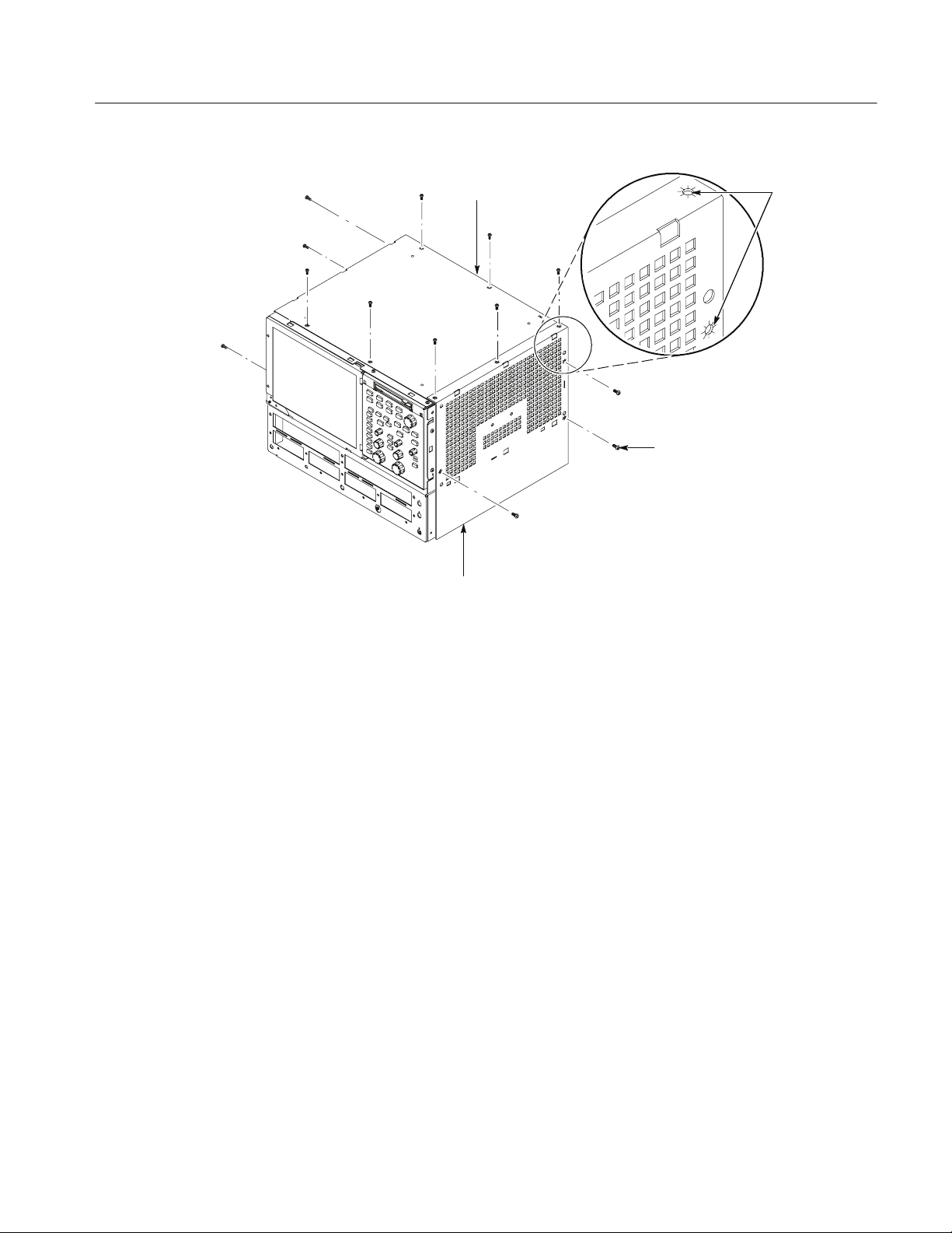
NOTE. All mounting screw holes are indicated by a star etched around the
mounting hole.
3. Remove the left and right covers: UseFigures3and4onpages13and14as
a guide.
a. Remove the thirteen T-15 Torxdrive screws that secure the covers to the
top and both sides of the chassis.
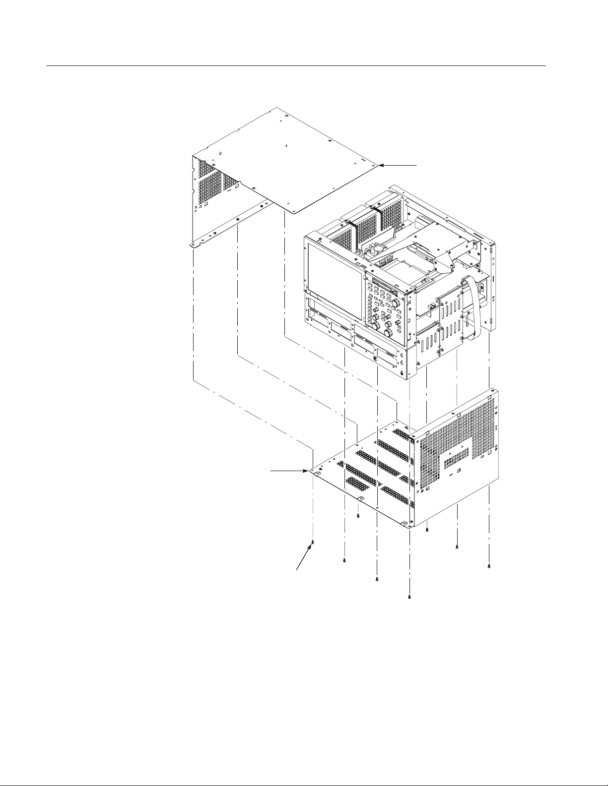
b. Remove the nine T-15 Torxdrive screws that secure the covers to the
bottom of the chassis.
c. Pull the bottom-right cover down and slide to the right to remove from
the instrument. Pull the top-left cover upward and slide to the left to
remove from the instrument.
CAUTION. Take care not to bind or snag the covers on the instrument’s internal
cabling as you remove or install.
4. Reinstallation: Do in reverse steps a through c to reinstall the cabinet.
12
CSA/TDS8UP, CSA/TDS8BUP, and CSA/TDS82UP Option MU1 Upgrade Kit
Page 15
Installation Instructions
Left side cover
Right side cover
Figure 3: Cover removal
All left and right
cover mounting
holes are
indicated as
shown.
T-15 Torxdrive
screw (13)
CSA/TDS8UP, CSA/TDS8BUP, and CSA/TDS82UP Option MU1 Upgrade Kit
13
Page 16
Installation Instructions
Left side cover
14
Right side cover
T-15 Torxdrive
screw (9)
Figure 4: Cover removal
CSA/TDS8UP, CSA/TDS8BUP, and CSA/TDS82UP Option MU1 Upgrade Kit
Page 17
Installation Instructions
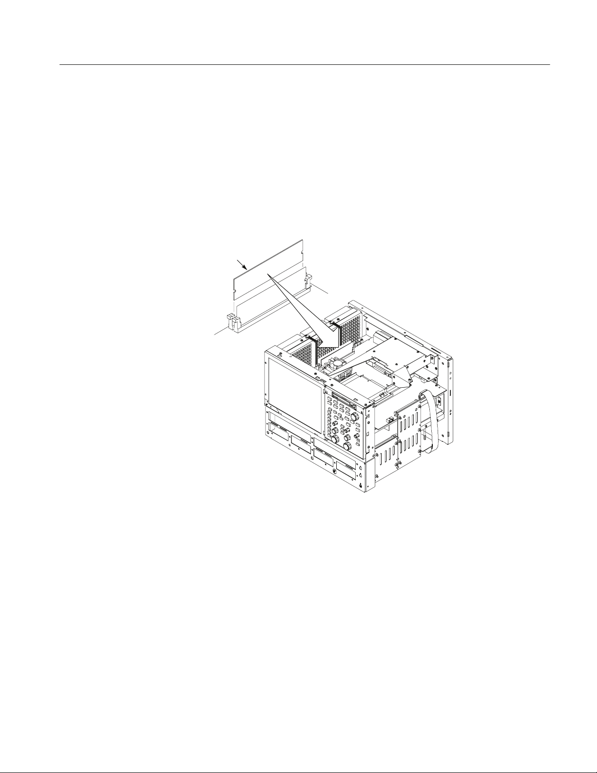
Install and Reassemble
1. Locate the memory module slot. See Figure 5 for the location of the memory
slots.
2. Install the 256 MB memory module from the kit into the empty slot on the
NLX circuit board.
3. Verify that the memory module is fully seated into the slot and that it is
secured in place by the the tabs at each end of the memory module.
4. Reassemble the instrument by performing the steps in reverse order.
256 MB
memory module
Figure 5: 256 MB memory installation
Verify Operation
This section contains instructions to check that the additional memory which you
installed is functioning.
1. Connect the power cord to the rear panel of the instrument and to the mains
power.
2. Switch the power switch on the rear panel to the on position.
3. Push the Standby/On button to power on the instrument.
4. After the instrument application opens, select Minimize from the File menu
to minimize the application.
CSA/TDS8UP, CSA/TDS8BUP, and CSA/TDS82UP Option MU1 Upgrade Kit
15
Page 18

Installation Instructions
5. Right click on the My Computer icon.
6. Select Properties from the pop-up menu.
7. Select the Performance tab in the Properties dialog box.
8. Check that Memory lists the correct amount of RAM.
g End of document g
16
CSA/TDS8UP, CSA/TDS8BUP, and CSA/TDS82UP Option MU1 Upgrade Kit
 Loading...