


Service Manual
CSA8000 Series
Communications Signal Analyzers,
TDS8000 Series
Digital Sampling Oscilloscopes,
and Modules
071-0438-07
Warning
The servicing instructions are for use by qualified
personnel only. To avoid personal injury, do not
perform any servicing unless you are qualified to
do so. Refer to all safety summaries prior to
performing service.
www.tektronix.com

Copyright © Tektronix. All rights reserved. Licensed software products are owned by Tektronix or its subsidiaries or
suppliers, and are protected by national copyright laws and international treaty provisions.
Tektronix products are covered by U.S. and foreign patents, issued and pending. Information in this publication supercedes
that in all previously published material. Specifications and pri ce change privileges reserved.
TEKTRONIX and TEK are registered trademarks of Tektronix, Inc.
Contacting Tektronix
Tektronix, Inc.
14200 SW Karl Braun Drive
P.O. Box 500
Beaverton, OR 97077
USA
For product information, sales, service, and technical support:
H In North America, call 1-800-833-9200.
H Worldwide, visit www.tektronix.com to find contacts in your area.

Warranty 2
Tektronix warrants that this product will be free from defects in materials and workmanship for a period of one (1) year
from the date of shipment. If any such product proves defective during this warranty period, Tektronix, at its option, either
will repair the defective product without charge for parts and labor, or will provide a replacement in exchange for the
defective product. Parts, modules and replacement products used by Tektronix for warranty work may be new or
reconditioned to like new performance. All replaced parts, modules and products become the property of Tektronix.
In order to obtain service under this warranty, Customer must notify Tektronix of the defect before the expiration of the
warranty period and make suitable arrangements for the performance of service. Customer shall be responsible for
packaging and shipping the defective product to the service center designated by Tektronix, with shipping charges prepaid.
Tektronix shall pay for the return of the product to Customer if the shipment is to a location within the country in which the
Tektronix service center is located. Customer shall be responsible for paying all shipping charges, duties, taxes, and any
other charges for products returned to any other locations.
This warranty shall not apply to any defect, failure or damage caused by improper use or improper or inadequate
maintenance and care. Tektronix shall not be obligated to furnish service under this warranty a) to repair damage resulting
from attempts by personnel other than Tektronix representatives to install, repair or service the product; b) to repair
damage resulting from improper use or connection to incompatible equipment; c) to repair any damage or malfunction
caused by the use of non-Tektronix supplies; or d) to service a product that has been modified or integrated with other
products when the effect of such modification or integration increases the time or difficulty of servicing the product.
THIS WARRANTY IS GIVEN BY TEKTRONIX WITH RESPECT TO THE PRODUCT IN LIEU OF ANY OTHER
WARRANTIES, EXPRESS OR IMPLIED. TEKTRONIX AND ITS VENDORS DISCLAIM ANY IMPLIED
WARRANTIES OF MERCHANTABILITY OR FITNESS FOR A PAR TICULAR PURPOSE. TEKTRONIX’
RESPONSIBILITY TO REPAIR OR REPLACE DEFECTIVE PRODUCTS IS THE SOLE AND EXCLUSIVE REMEDY
PROVIDED TO THE CUSTOMER FOR BREACH OF THIS WARRANTY . TEKTRONIX AND ITS VENDORS WILL
NOT BE LIABLE FOR ANY INDIRECT, SPECIAL, INCIDENTAL, OR CONSEQUENTIAL DAMAGES
IRRESPECTIVE OF WHETHER TEKTRONIX OR THE VENDOR HAS ADV ANCE NOTICE OF THE POSSIBILITY
OF SUCH DAMAGES.


Table of Contents
Operating Information
General Safety Summary ix...................................
Service Safety Summary xi....................................
Preface xiii...................................................
Manual Structure xiii................................................
Manual Conventions xiii..............................................
Related Documentation xiv...........................................
Installation 1--1...............................................
Check the Environmental Requirements 1--1..............................
Site Considerations 1--1...........................................
Operating Requirements 1--1.......................................
Rackmount Requirements 1--2......................................
Install the Sampling Modules 1--2.......................................
Check Your Sampling Module Manual(s) 1--2..........................
Maximum Configuration 1--3.......................................
Connect the Peripherals 1--3...........................................
Power On the Instrument 1--5..........................................
Powering Off the Instrument 1--6.......................................
Software Installation 1--7..............................................
Description 1--7.................................................
Software Release Notes 1--7........................................
Operating System Reinstallation 1--7.................................
System Hard Drive Rebuild 1--8....................................
System Diagnostics 1-- 8...........................................
Windows Safe Mode 1--8..........................................
Theory of Operation
Theory of Operation 2--1.......................................
Logic Conventions 2--1...............................................
Mainframe Overview 2--1.............................................
Input Signal Path 2--1.............................................
Display Panel 2--2................................................
Front Panel 2--2..................................................
Rear Panel 2--2..................................................
Low Voltage Power Supply 2--2.....................................
Fans 2--3.......................................................
Electrical Sampling Modules Overview 2--3..............................
80E01, 80E02, 80E03, 80E06, 80E07, and 80E09 Sampling Modules 2--3...
80E04, 80E08, and 80E10 TDR/Sampling Modules 2--4.................
CSA8000 & TDS8000 Series Instruments and Modules
i

Table of Contents
Optical Sampling Modules Overview 2--5................................
80C01 Optical Sampling Module 2--7................................
80C02 Optical Sampling Module 2--7................................
80C03 Optical Sampling Module 2--8................................
80C04 Optical Sampling Module 2--8................................
80C05 Optical Sampling Module 2--9................................
80C06 Optical Sampling Module 2--9................................
80C07 Optical Sampling Module 2--9................................
80C07B Optical Sampling Module 2--10...............................
80C08 Optical Sampling Module 2--10................................
80C08B Optical Sampling Module 2--10...............................
80C08C Optical Sampling Module 2--11...............................
80C09 Optical Sampling Module 2--11................................
80C10 Optical Sampling Module 2--11................................
80C11 Optical Sampling Module 2--12................................
80C12 Optical Sampling Module 2--12................................
80A01 Trigger Prescale Preamplifier Module 2--12..........................
80A02 EOS/ESD Protection Module 2--13.................................
80A05 Electrical Clock Recovery Module 2--13............................
80A06 PatternSync Trigger Module 2--14.................................
82A04 Phase Reference Module 2--14....................................
Adjustment Procedures
Maintenance
Adjustment Interval 3--1..............................................
Adjustment Environment 3--1..........................................
Adjustment After Repair 3--1..........................................
Required Equipment 3--2..............................................
Instrumentation Setup 3--2.............................................
Main Instrument Adjustments 3--3......................................
DC Calibrator Adjust 3--3..........................................
DC Calibrator Adjust Verification 3--4...............................
Internal 10 MHz Adjust 3--5........................................
Preventing ESD 4--1.................................................
Inspection and Cleaning 4--2...........................................
General Care 4--2................................................
Flat Panel Display Cleaning 4--2....................................
Exterior 4--3....................................................
Interior 4--4.....................................................
Removal and Installation Procedures 4--7.........................
Preparation 4--7.....................................................
Procedures for External Modules 4--9....................................
Front-Panel Knobs 4--9............................................
Trim and Carrying Handle 4--10.....................................
Bottom Cover 4--11...............................................
Covers 4--13.....................................................
Line Fuses and AC power cord connector 4--16.........................
ii
CSA8000 & TDS8000 Series Instruments and Modules

Table of Contents
Procedures for Modules 4--21...........................................
Front Panel Assembly 4--21.........................................
Front Panel Board 4--23............................................
Front Panel Keypad 4--24...........................................
Display Assembly 4-- 25............................................
Display Adapter Board 4--27........................................
Standby/On Switch Flex Circuit Removal 4--29.........................
Floppy Disk Drive 4--31............................................
Hard Disk Drive 4--32.............................................
CD Drive 4--34...................................................
Fan Assembly Removal 4--35........................................
Front and Rear Power Distribution Boards 4--37.........................
Low-Voltage Power Supply 4--38.....................................
NLX Board 4--40.................................................
Microprocessor 4--43..............................................
PC Processor Board 4--45...........................................
Acquisition Assembly 4--47.........................................
Large Module Interface Circuit Board 4--53............................
Module Slot Doors 4 --55...........................................
Electrical Modules 4--64............................................
Exchanging the Electrical Sampling Module 4--65..........................
Replacing the sampling module chassis 4--65...........................
Reinstalling exchange module serial number 4--65.......................
Optical Modules 4--66.............................................
80A00 and 82A00 Series Modules 4--67...............................
Troubleshooting 4--69...........................................
Check for Common Problems 4--69......................................
Equipment Required 4 --72..............................................
Isolating Failures between the 80E0X/80C0X Modules or the Mainframe 4--72...
Isolating to a Board if Power Will Not Come Up 4--73....................
Checking the Power Supply Voltages 4--74...............................
If the instrument Will Not Boot 4--75.................................
Booting Into Windows 4--76.........................................
PPC and NLX PC Diagnostics 4--76......................................
Power-On Diagnostics 4--76.........................................
QAPlus/Win 4--76.................................................
Diagnostics 4--77.................................................
Firmware Updates 4--77................................................
After Repair 4--78....................................................
Installing the Instrument Model and Serial Number 4--78.....................
Update/Restore the NLX Board CMOS 4--79...............................
Repackaging Instructions 4--81...................................
Packaging 4--81......................................................
Shipping to the Service Center 4--81......................................
Diagrams
Symbols 5--1.......................................................
CSA8000 and TDS8000 Series Block Diagram 5--2.........................
Electrical Sampling Modules Block Diagram 5--3..........................
Optical Sampling Modules Block Diagrams 5--4...........................
80A01 Block Diagram 5--26............................................
CSA8000 & TDS8000 Series Instruments and Modules
iii

Table of Contents
Replaceable Parts
80A02 Block Diagram 5--27............................................
80A05 Block Diagram 5--28............................................
80A06 Block Diagram 5--29............................................
82A04 Block Diagram 5--30............................................
Replaceable Parts List 6-- 1......................................
Parts Ordering Information 6--1.........................................
Module Servicing 6--1............................................
Using the Replaceable Parts List 6--2....................................
iv
CSA8000 & TDS8000 Series Instruments and Modules

List of Figures
Table of Contents
Figure 1--1: Compartments for sampling modules 1--2...............
Figure 1--2: Locations of peripheral connectors on rear panel 1--4.....
Figure 1--3: Line fuse and power cord connector locations,
rear panel 1-- 5.............................................
Figure 1-- 4: On/Standby switch location 1--6.......................
Figure 3-- 1: Adjustment setup using the DMM 3-- 3..................
Figure 3-- 2: Adjustment setup using the signal generator 3-- 5.........
Figure 4--1: Knob removal 4--9..................................
Figure 4--2: Trim removal 4--11...................................
Figure 4--3: Bottom cover removal 4--12............................
Figure 4--4: Cover removal 4--14..................................
Figure 4--5: Cover removal 4--15..................................
Figure 4--6: Line fuses and line cord removal 4--17...................
Figure 4--7: External modules 4--18................................
Figure 4-- 8: Internal modules 4-- 19................................
Figure 4-- 9: Acquisition modules 4-- 20.............................
Figure 4--10: Front panel assembly removal 4--22....................
Figure 4--11: J1 flex cable connector removal 4--23...................
Figure 4--12: Front panel board and keyboard removal 4--24..........
Figure 4--13: Display removal 4--26................................
Figure 4--14: Touch panel and LCD assembly removal 4--27...........
Figure 4--15: Display adaptor board removal 4--28...................
Figure 4--16: Connector clip assembly 4--28.........................
Figure 4-- 17: Standby/On switch flex circuit removal 4--30............
Figure 4--18: Floppy disk drive removal 4--31.......................
Figure 4--19: Hard drive disk removal 4--33.........................
Figure 4--20: Removing the hard disk drive from the cartridge 4--33....
Figure 4--21: CD drive and bracket removal 4--35....................
Figure 4--22: Fan assembly removal 4--36...........................
Figure 4--23: Front and rear power distribution board removal 4--37...
Figure 4-- 24: Low-voltage power supply removal 4--39................
Figure 4--25: NLX assembly removal 4--41..........................
Figure 4--26: Riser adapter and NLX board removal 4--42............
Figure 4--27: Microprocessor removal 4--44.........................
CSA8000 & TDS8000 Series Instruments and Modules
v

Table of Contents
Figure 4--28: Processor board removal 4--46........................
Figure 4--29: T-10 screws and threaded posts 4--48...................
Figure 4--30: Thermal cover removal (8200 only) 4--49................
Figure 4--31: Acquisition circuit board assembly removal (8000) 4--50...
Figure 4--32: Acquisition circuit board assembly removal (8000B) 4--51.
Figure 4--33: Acquisition circuit board assembly removal (8200) 4--52...
Figure 4--34: Large module interface circuit board removal
(8000 and 8000B) 4--54.......................................
Figure 4--35: Large module interface circuit board removal (8200) 4--55.
Figure 4--36: Small and Large module chassis removal 4--57...........
Figure 4--37: Module door spring removal 4--59.....................
Figure 4--38: Module slot door removal 4--60........................
Figure 4--39: Module ejector handles removal 4--62..................
Figure 4--40: Spring arm position 4--63............................
Figure 4--41: Electrical module hardware removal 4--64..............
Figure 4--42: Optical module cover removal 4--66....................
Figure 4--43: 80A00 and 82A00 series parts removal
(80A01 shown) 4--67.........................................
Figure 4--44: Location of power-on and over current LEDs 4--73.......
Figure 4--45: Location of debug pins 4--74..........................
Figure 4--46: Connectors J1 and J2 4--75...........................
Figure 5--1: Block diagram for CSA8000 and TDS8000
Series Instruments 5--2......................................
Figure 5--2: Block diagram for the 80E00 Series Electrical
Sampling Modules 5-- 3......................................
Figure 5--3: 80C01 Optical sampling block diagram 5--4.............
Figure 5--4: 80C01 Optical sampling with clock recovery block
diagram 5--5..............................................
Figure 5--5: 80C02 Optical sampling block diagram 5--6.............
Figure 5--6: 80C02 Optical sampling with clock recovery block
diagram 5--7..............................................
Figure 5--7: 80C03 Optical sampling block diagram 5--8.............
Figure 5--8: 80C03 Optical sampling with clock recovery block
diagram 5--9..............................................
Figure 5--9: 80C04 Optical sampling block diagram 5--10.............
Figure 5--10: 80C04 Optical sampling block diagram with clock
recovery 5--1 1..............................................
Figure 5--11: 80C05 Optical sampling block diagram 5--12............
Figure 5--12: 80C06 Optical sampling block diagram 5--13............
vi
CSA8000 & TDS8000 Series Instruments and Modules

Table of Contents
Figure 5--13: 80C07 and 80C07B Optical sampling block diagram 5--14.
Figure 5--14: 80C07 and 80C07B Optical sampling with CR1 clock
recovery block diagram 5--15.................................
Figure 5--15: 80C08/80C08B/80C08C Optical sampling block
diagram 5--16..............................................
Figure 5--16: 80C08/80C08B/80C08C Optical sampling with CR1,
CR2, & CR4 clock recovery block diagram 5--17.................
Figure 5--17: 80C09 Optical sampling block diagram 5--18............
Figure 5--18: 80C09 Optical sampling with CR1 clock recovery
block diagram 5--19.........................................
Figure 5--19: 80C10 Optical sampling block diagram 5--20............
Figure 5--20: 80C11 Optical sampling block diagram 5--21............
Figure 5--21: 80C11 Optical sampling with CR1 clock recovery
option block diagram 5--22...................................
Figure 5--22: 80C11 Optical sampling with CR2 and CR3 clock
recovery option block diagram 5--23...........................
Figure 5--23: 80C11 Optical sampling with CR4 clock recovery
option block diagram 5--24...................................
Figure 5--24: 80C12 Optical sampling block diagram 5--25............
Figure 5--25: 80A01 block diagram 5--26...........................
Figure 5--26: 80A02 block diagram 5--27...........................
Figure 5--27: 80A05 block diagram 5--28...........................
Figure 5--28: 80A06 block diagram 5--29...........................
Figure 5--29: 82A04 block diagram 5--30...........................
Figure 6--1: External parts 6--4..................................
Figure 6-- 2: Front panel and drives 6-- 7...........................
Figure 6-- 3: Power supply 6-- 10...................................
Figure 6--4: Acquisition 6--12.....................................
Figure 6--5: 8000 and 8000B coaxial cables 6--14.....................
Figure 6--6: 8200 coaxial cables 6--16..............................
Figure 6--7: 80E01, 80E02, 80E03, and 80E04 modules 6--18...........
Figure 6--8: 80E05 module (Option 10G shown) 6--19................
Figure 6--9: 80E06 module 6--20..................................
Figure 6--10: 80E07, 80E08, 80E09, and 80E10 modules 6--21..........
Figure 6--11: Optical modules 6--22................................
Figure 6--12: 80A01 module 6--23.................................
Figure 6--13: 82A04 module 6--24.................................
Figure 6--14: 80A06 module 6--26.................................
CSA8000 & TDS8000 Series Instruments and Modules
vii

Table of Contents
List of Tables
Table 1--1: Additional accessory connection information 1--3.........
Table 1--2: Line fuses 1--5......................................
T able 2--1: Module optical/electrical split 2--6......................
Table 3--1: Adjustments required for module replaced 3--1...........
Table 3--2: Required equipment and materials 3--2.................
T able 4--1: External inspection check list 4--3......................
T able 4--2: Internal inspection check list 4--4......................
Table 4--3: Tools required for module removal 4--8.................
Table 4--4: Failure symptoms and possible causes 4--69...............
Table 4--5: Power supply voltages 4--75............................
Table 4--6: Action required for module replaced 4--78................
viii
CSA8000 & TDS8000 Series Instruments and Modules

General Safety Summary
Review the following safety precautions to avoid injury and prevent damage to
this product or any products connected to it. To avoid potential hazards, use this
product only as specified.
Only qualified personnel should perform service procedures.
While using this product, you may need to access other parts of the system. Read
the General Safety Summary in other system manuals for warnings and cautions
related to operating the system.
ToAvoidFireor
Personal Injury
Use Proper Power Cord. Use only the power cord specified for this product and
certified for the country of use. Power cord needed only in the mainframe, not
modules.
Connect and Disconnect Properly. Do not connect or disconnect probes or test
leads while they are connected to a voltage source.
Ground the Product. The mainframe is grounded through the grounding
conductor of the power cord. To avoid electric shock, the grounding conductor
must be connected to earth ground. Before making connections to the input or
output terminals of the product, ensure that the product is properly grounded.
Ground the Product. The modules are indirectly grounded through the grounding
conductor of the mainframe power cord. To avoid electric shock, the grounding
conductor must be connected to earth ground. Before making connections to the
input or output terminals of the product, ensure that the product is properly
grounded.
Observe All Terminal Ratings. To avoid fire or shock hazard, observe all ratings
and markings on the product. Consult the product manual for further ratings
information before making connections to the product.
Do not apply a potential to any terminal, including the common terminal, that
exceeds the maximum rating of that terminal.
Do Not Operate Without Covers. Do not operate this product with covers or panels
removed.
Use Proper Fuse. Use only the fuse type and rating specified for this product.
Avoid Exposed Circuitry. Do not touch exposed connections and components
when power is present.
Wear Eye Protection. Wear eye protection if exposure to high-intensity rays or
laser radiation exists.
Do Not Operate With Suspected Failures. If you suspect there is damage to this
product, have it inspected by qualified service personnel.
CSA8000 & TDS8000 Series Instruments and Modules
ix

General Safety Summary
Do Not Operate in Wet/Damp Conditions.
Do Not Operate in an Explosive Atmosphere.
Keep Product Surfaces Clean and Dry.
Provide Proper Ventilation. Refer to the manual’s installation instructions for
details on installing the product so it has proper ventilation.
Symbols and Terms
Terms in this Manual. These terms may appear in this manual:
WARNING. Warning statements identify conditions or practices that could result
in injury or loss of life.
CAUTION. Caution statements identify conditions or practices that could result in
damage to this product or other property.
Terms on the Product. These terms may appear on the product:
DANGER indicates an injury hazard immediately accessible as you read the
marking.
WARNING indicates an injury hazard not immediately accessible as you read the
marking.
CAUTION indicates a hazard to property including the product.
Symbols on the Product. The following symbols may appear on the product:
CAUTION
Refer to Manual
Mains Disconnected
OFF (Power)
WARNING
High Voltage
Mains Connected
ON (Power)
x
Protective Ground
(Earth) Terminal
Standby
CSA8000 & TDS8000 Series Instruments and Modules

Service Safety Summary
Only qualified personnel should perform service procedures. Read this Service
Safety Summary and the General Safety Summary before performing any service
procedures.
Do Not Service Alone. Do not perform internal service or adjustments of this
product unless another person capable of rendering first aid and resuscitation is
present.
Disconnect Power. To avoid electric shock, switch off the instrument power, then
disconnect the power cord from the mains power.
Use Care When Servicing With Power On. Dangerous voltages or currents may
exist in this product. Disconnect power, remove battery (if applicable), and
disconnect test leads before removing protective panels, soldering, or replacing
components.
To avoid electric shock, do not touch exposed connections.
CSA8000 & TDS8000 Series Instruments and Modules
xi

Service Safety Summary
xii
CSA8000 & TDS8000 Series Instruments and Modules

Preface
Manual Structure
This is the service manual for the:
H CSA8000, CSA8000B, and CSA8200 Communications Signal Analyzers
H TDS8000, TDS8000B, and TDS8200 Digital Sampling Oscilloscopes
H modules that install in the instruments (except the 80A03 module)
NOTE. The 80A03 instruction manual contains its own specifications and
servicing information.
Read this preface to learn how this manual is structured, what conventions it
uses, and where you can find other information related to servicing this product.
Read the Introduction following this preface for safety and other important
background information needed before servicing this product.
This manual is divided into chapters, which are made up of related subordinate
topics. These topics can be cross referenced as sections.
Manual Conventions
Modules
Replaceable Parts
Safety
Be sure to read the introductions to all procedures. These introductions provide
important information needed to do the service correctly, safely, and efficiently.
This manual uses certain conventions that you should become familiar with
before attempting service.
Throughout this manual, the term module appears. A module is composed of
electrical and mechanical assemblies, circuit cards, interconnecting cables, and a
user-accessible front panel. References to a module are different than references
to products such as “Sampling modules”. “Phase Reference modules”, or
“Accessory modules” which are products installed in the instrument compartments.
This manual refers to any field-replaceable assembly or mechanical part by its
name or generically as a replaceable part. In general, a replaceable part is any
circuit board or assembly, such as a hard disk drive, or a mechanical part, such as
I/O port connectors, that is listed in the replaceable parts list of Chapter 8.
Symbols and terms related to safety appear in the General Safety Summary found
at the beginning of this manual.
CSA8000 & TDS8000 Series Instruments and Modules
xiii

Preface
Related Documentation
The following documents relate to the instruments this service manual supports:
H CSA8200 and TDS8200 Quick Start User manual. Tektronix part number
071-1482-XX. This document also contains specification changes when
using the 82A04 Phase Reference module.
H CSA8000 and TDS8000 Specifications and Performance Verification
manual. Tektronix part number 071-xxxx-XX.
H CSA8000 and TDS8000 Online Help. Installed with the application software
and accessed from the instrument Help menu.
H CSA8000 & TDS8000 Programmer Guide. An online document accessed
from the instrument Help menu.
H 80E01, 80E02, 80E03, 80E04, and 80E06 Electrical Sampling Modules
User manual. Tektronix part number 071-0434-XX.
H 80E07, 80E08, 80E09, and 80E10 Electrical Sampling Remote Modules
User manual. Tektronix part number 071-2038--XX.
H 80C00 Series Optical Sampling Modules User manual. Tektronix part
number 071-0435-XX.
H 80A01 Trigger Prescale Limiting Preamplifier Module User manual.
Tektronix part number 071-0873-XX.
H 80A02 EOS/ESD Protection Module Instructions. Tektronix part number
071-1317-XX
H 80A03 TekConnect Probe Interface Module Instructions. Tektronix part
number 071-1298-XX.
H 80A05 Electrical Clock Recovery Module User manual. Tektronix part
number 071-1467-XX.
H 80A06 PatternSync Trigger Module Instructions. Tektronix part number
071-xxx-XX.
H CSA8000/TDS8000 Rackmount Kit Instructions. Tektronix part number
071-0696-XX.
H TDR Z-Meas Application Online Help. Ships with this product on a separate
CD. Provides information about this TDR Impedance Measuring application
that implements the TDR calibration procedures specified by the
IPC TM-650 test method.
xiv
H Fast NRZ Application Online Help. Ships with this product on a separate
CD. Provides information about this application that improves throughput
for optical eye-pattern mask testing.
CSA8000 & TDS8000 Series Instruments and Modules

Operating Information


Installation
This section covers installation of the instrument, addressing the following
topics:
H Check the Environment Requirements on page 1--1
H Install the Sampling Modules on page 1--2
H Connect the Peripherals on page 1--3
H Power On the Instrument on page 1--5
H Powering Off the Instrument on page 1--6
The basic operating software is already installed on the hard disk. If reinstallation of software becomes needed, see the following topic:
H Software Installation on page 1--7
Check the Environmental Requirements
Site Considerations
Operating Requirements
Read this section before attempting any installation procedures. This section
describes site considerations, power requirements, and ground connections for
your instrument.
The instrument is designed to operate on a bench or on a cart in the normal
position (on the bottom feet). For proper cooling, at least two inches (5.1 cm) of
clearance is recommended on the sides of the instrument.
You can also operate the instrument while it rests on its rear feet. Make sure that
you properly route any cables coming out of the rear of the instrument to avoid
damaging them.
CAUTION. Keep the bottom of the instrument clear of obstructions to ensure
proper cooling.
Specifications in chapter 1 list the operating requirements for the instrument.
Power source and temperature, humidity, and altitude are listed.
CSA8000 & TDS8000 Series Instruments and Modules
1- 1

Installation
Rackmount Requirements
If this instrument is rackmounted, see the TDS8000 & CSA8000 Rackmount
Instructions for additional site considerations or operating requirements. This
document ships with the Option 1R (rackmount kit).
Install the Sampling Modules
CAUTION. Do not install or remove any sampling modules while the instrument is
powered on.
Always power the instrument down before attempting to remove or insert any
sampling module.
WARNING. Sampling modules are inherently vulnerable to static damage. Always
observe static-safe procedures and cautions as outlined in your sampling module
user manual.
Check Your Sampling
Module Manual(s)
Read the sampling-module user manual for instructions on how to install your
sampling modules.
Large-module compartments (2)
Small-module compartments (4)
Connect ESD wrist strap here
NOTE. After first installing a sampling module(s) or after moving a sampling
module from one compartment to another, you should run compensation from the
Utilities menu to ensure the instrument meets its accuracy specifications. You
must run a compensation (accessed from the Utilities menu) whenever the
extender configuration is changed from that present at the last compensation. In
short, if you install or remove an 80E00 extender, run a compensation. If you
exchange a extender for one of a different length, run a compensation.
Figure 1--1 shows compartments for both large and small sampling modules,
along with the plug-in connector for the ESD wrist strap that you must use to
install and remove these modules.
Figure 1- 1: Compartments for sampling modules
1- 2
CSA8000 & TDS8000 Series Instruments and Modules

Installation
Maximum Configuration
You can install up to two large sampling modules and four small modules for a
maximum of 10 inputs (CSA and TDS 8000 and 8000B) or 12 inputs (CSA and
TDS 8200). Of these inputs, only eight inputs can be active at one time. Also,
note that installing a large module may disable a small-module compartment.
Refer to the user manual for compartment interaction for the various CSA and
TDS 8000 Series mainframes.
Install probes, cables, and other connection accessories to your sampling
modules as appropriate for your application and sampling module. Again,
consult your sampling-module and connection-accessory manuals. Continue with
the next section after installing the sampling modules.
Connect the Peripherals
The peripheral connections are mostly the same as those you would make on a
personal computer. The connection points are shown in Figure 1--2. See
Table 1--1 on page 1--3 for additional connection information.
WARNING. Before installing peripheral accessories to connectors (mouse, keyboard,
etc.), power down the instrument. See Powering Off the Instrument on page 1--6.
Table 1- 1: Additional accessory connection information
Item Description
Monitor If you use a non-standard monitor, you may need to change the the
Windows display settings to achieve the proper resolution for your monitor.
Printer Connect the printer to the EPP (enhanced parallel port) connector directly. If
your printer has a DB-25 connector, use the adapter cable that came with
your printer to connect to the EPP connector.
Rackmount Refer to the CSA8000 & TDS8000 Rackmount Installation Instructions for
information on installing the rackmount kit.
Other Refer to the Appli cation release notes (readme.txt) in the C:\Program
Files\TDSCSA8000\System directory of the instrument for possible
additional accessory installation information not covered in this manual.
CSA8000 & TDS8000 Series Instruments and Modules
1- 3

Installation
Description..........................Icon/Label Locations
Monitor.............
Printer......................
RS-232.................
Network.............................
PS2 mouse
PS2 keyboard
1,2
......................
1,2
..............
USB................................
Audio line out.......................
Audio line in........................
Removable hard drive.....................
CD drive.........................
GPIB...........
Monitor....................
3
Card slot
...........
Gated trigger...........
1
Product ships with a USB keyboard, that plugs into the USB port, and a USB mouse that plugs into the back of the keyboard
2
Some instruments ship with the keyboard and mouse ports reversed.
3
Card slot not available on CSA/TDS8000B or CSA/TDS8200 instruments. The card slot is disabled in instruments running Microsoft Windows 2000.
Figure 1- 2: Locations of peripheral connectors on rear panel
1- 4
CSA8000 & TDS8000 Series Instruments and Modules

Power On the Instrument
Follow these steps to power on the instrument for the first time.
1. Check that the line fuses are correct for your application. Both fuses must be
Table 1- 2: Line fuses
Fuse type Rating Fuse part number
0.25 x 1.250 inch 8 A, fast blow, 250 V 159-0046-00 200-2264-00
5x20mm 6.3 A, fast blow, 250 V 159-0381-00 200-2265-00
Installation
the same rating and type. Fuse types require a unique cap and fuseholder. See
Table 1--2 and Figure 1--3.
Cap & fuseholder
part number
Fuses AC powerPower switch
Figure 1- 3: Line fuse and power cord connector locations, rear panel
CAUTION. Connect accessories (such as a PS2 keyboard and mouse, and other
accessories) before applying power to the product. Some accessories can be
damaged if connecting or disconnecting with the instrument power on.
USB devices can be plugged or unplugged without first turning power off.
2. Connect the keyboard and mouse, observing the caution above.
NOTE. Connection of the keyboard and mouse is optional. You can operate most
features without them, using the front-panel controls and the touchscreen.
3. Connect the power cord.
4. Turn the Power switch on at the rear panel. (See Figure 1--3 on page 1--5 for
switch location.)
5. Push the On/Standby switch to power on the instrument (see Figure 1--4 for
the switch location).
CSA8000 & TDS8000 Series Instruments and Modules
1- 5

Installation
Switch
Figure 1- 4: On/Standby switch location
6. Wait for the boot routine and low-level self test to complete.
7. Follow any instructions on the screen.
The internal setup software will automatically configure your instrument and
install all required devices, depending on the installed accessories.
Powering Off the Instrument
The instrument has a built-in soft power-down function that safely powers down
the instrument when you push the On/Standby button. You do not need to close
the UI application or Windows before using the On/Standby button.
To completely remove power to the instrument, first soft power-down the
instrument using the On/Standby button, and then set the power switch on the
rear panel to off.
You can restore the UI application to the screen by clicking its button in the
Windows Task bar.
1- 6
CSA8000 & TDS8000 Series Instruments and Modules

Software Installation
Installation
This section describes how to install the system software found on the 8000
Series OS Restore CDs that accompany this product. The instrument ships with
the product software installed, so only perform these procedures if reinstallation
becomes necessary.
Description
Software Release Notes
The product software comprises two parts:
H Microsoft Windows. The Microsoft Windows operating system comes
preinstalled on the instrument. Microsoft Windows is the operating system
on which the user-interface application of this product runs. The CD-
ROM(s) included with your instrument contain the Windows operating
system which can be used to rebuild the instrument hard drive.
If you need to reinstall Windows, you may be able to do so without
rebuilding the instrument hard drive. See Operating System Reinstallation on
page 1--7 for more information.
H User Interface (UI) Application. The UI application complements the
hardware controls of the front panel, allowing complete set up of all
instrument features. The CD-ROM(s) included with your instrument contain
the UI application for reinstallation if rebuilding the hard drive.
Tektronix provides updates to the user interface application on a regular
basis. Updates can be obtained by visiting the Tektronix Web site at
www.tektronix.com.
Read the software release notes in the Release Notes file (or Readme file for
earlier versions), if present, on the CD-ROM containing the user interface
application before performing any installation procedures. This file contains
additional installation and operation information that supercedes other product
documentation.
After installation, you can also read the copy from a directory on the product:
C:\Programs Files\TDSCSA8000\System
Operating System
Reinstallation
CSA8000 & TDS8000 Series Instruments and Modules
If reinstalling Microsoft Windows becomes necessary, use the Windows
Operating System restore CD(s) that came with your instrument. Follow the
installation procedures provided with the CD(s). The procedures vary between
instruments and the version of Microsoft Windows being installed.
NOTE. Only do the reinstall if the Microsoft Windows operating system is
missing or corrupted.
1- 7

Installation
System Hard Drive
Rebuild
System Diagnostics
Windows Safe Mode
If you cannot reboot from the instrument hard drive, you must rebuild the
instrument hard drive. This process will return the hard disk to the its original
condition present when the instrument shipped.
Data and programs you may have installed will be lost when rebuilding the hard
drive.
If you must rebuild the system hard drive, use the System Rebuild CD(s) that
shipped with the instrument. Follow the instructions in the booklet found in the
CD case.
In case of instrument problems, you may wish to run the system diagnostics. If
needed, you can see the procedure in the Performance Verification and Specifica-
tions manual.
If the instrument is turned off before the operating system boots, or if you’ve
installed a third-party product with a driver incompatible with instrument start
up, Windows will open in Safe mode. The touchscreen will be inoperable;
therefore, you must install the standard-accessory mouse and keyboard to operate
the instrument.
When you have finished investigating and removed any barrier to Windows
start-up, you can reboot. If the instrument no longer boots to Safe mode, you can
remove the keyboard and mouse if desired.
1- 8
CSA8000 & TDS8000 Series Instruments and Modules

Theory of Operation


Theory of Operation
This chapter describes the electrical operation of the instrument and sampling
modules. The diagrams in Chapter 9 show the interconnections of the major
circuit blocks.
Logic Conventions
The instrument contains many digital logic circuits. This manual refers to these
circuits with standard logic symbols and terms. Unless otherwise stated, all logic
functions are described using the positive-logic convention: the more positive of
the two logic levels is the high (1) state, and the more negative level is the low
(0) state. Signal states may also be described as “true” meaning their active state
or “false” meaning their nonactive state. The specific voltages that constitute a
high or low state vary among the electronic devices.
Mainframe Overview
This mainframe overview describes the basic operation of each functional circuit
block as shown in Figure 5--1 on page 5--2.
General
Input Signal Path
The instrument control system is a dual Wintel/PowerPC based processor board.
The platform features VGA resolution flat-panel display, transparent touch
screen and user front-panel with direct access to commonly used scope functions.
The instrument is also equipped with a mouse pointing device to facilitate access
to more advanced scope functions
A signal enters the instrument through a direct coaxial connection to the input
connector on a sampling module, or a real time probe connected to the sampling
module channel.
Acquisition System. The acquisition system conditions the input signals, samples
them, converts them to digital signals, and controls the acquisition process under
direction of the processor system. The acquisition system includes the multisource trigger, acquisition timebase, and acquisition mode generation and control
circuitry. The acquisition board is located in the bottom compartment of the
instrument and can accommodate four small slot sampling plug-ins, two large
slot plug-ins and a trigger/holdoff subsystem. Up to 8 vertical channels are
accommodated simultaneously . Channels 1 and 2 (CSA and TDS8000 and
8000B) or channels 1, 2, 3, and 4 (CSA and TDS8200) can be either large or
small slots. The presence of a module in one or both large slots displaces the
CSA8000 & TDS8000 Series Instruments and Modules
2- 1

Theory of Operation
small slot functionality in the corresponding small slots. The external trigger and
all small slot channels feature a Tekprobe Level 2 probe power connector for
additional front end signal conditioning functions like high input-impedance
real-time probes, if equipped on the sampling module.
Processor System. The processor system contains a dual Wintel/PowerPC. The
basic instrument configuration supports up to eight channels labeled Ch1 through
Ch 8, provides two external trigger inputs for direct and prescaled triggering
through built--in prescaler and is able to support two optional internal trigger
sources associated with the large slot channels.
Display Panel
Front Panel
Rear Panel
Color LCD display Active-matrix touch panel.
Display System. The display system sends the text and waveform information to
the display panel.
Touch Panel. The Display board sends information to the processor. Any changes
in their settings are reported to the processor system.
The front panel board reads the front-panel switches and knob sensors. Any
changes in their settings are reported to the processor system. The front panel
board also turns the LEDs on and off and generates the bell signal.
Front-panel menu switches are also read by the PPC processor board. The
processor sends any changes in menu selections to the processor system. The
ON/STBY switch is one of the menu switches. However, it is not read by the
front panel board, but passes through the front panel board to the low voltage
power supply.
The hard drive and CD Rom provides access to stored waveform data and to load
software to customized your instrument with your measurement needs. The
GPIB allows for external control of the instrument.
Low Voltage Power Supply
2- 2
You can make hardcopies on the GPIB and RS-232 ports. Other ports from the
front panel board: PC cardbus x 2 and cal adjust lock.
Outputs from the NLX board: SVGA, USB (1), sound, serial, parallel, Ethernet,
mouse, keyboard.
The low voltage power supply is a switching power converter with active power
factor control. It supplies power to all of the circuitry in the instrument.
The principal POWER switch, located on the rear panel, controls all power to the
instrument including the Low Voltage Power Supply. The ON/STBY switch,
CSA8000 & TDS8000 Series Instruments and Modules

Theory of Operation
located on the front panel, also controls all of the power to the instrument except
for part of the circuitry in the Low Voltage Power Supply.
The power supply sends a power fail (~PF) warning to the processor system if
the power is going down.
Fans
The fan assembly provides forced air cooling for the instrument. The fans are
controlled by the PPC processor.
Electrical Sampling Modules Overview
80E01, 80E02, 80E03,
80E06, 80E07, and 80E09
Sampling Modules
Table 2- 1: Electrical sampling module features
Feature 80E01 80E02 80E03 80E06 80E07 80E09
Number of independent channels 1 2 2 1 2 2
Bandwidth 50 GHz 12.5 GHz 20 GHz 70 GHz 30 GHz 60 GHz
Selectable bandwidths N.A. N.A. N.A. N.A. 20 GHz,
Signal connectors 2.4 mm
Remote sampler N.A. N.A. N.A. N.A. 2 meter cable 2 meter cable
The electrical sampling modules (non-TDR capable) are one- and two-channel
sampling modules. Their basic features are listed in the following table. (The
TDR capable sampling modules are describe later.)
40 GHz,
female
3.5 mm
female
3.5 mm
female
1.85 mm (V)
female
30 GHz
2.92 mm (K)
female
30 GHz,
60 GHz
1.85 mm (V)
female
For the two-channel modules, a single strobe delivered from the instrument
mainframe to both acquisition channels controls the timing of the strobe
assertion to both channels. If channel-to-channel deskew is zero and the channel
delays (if equipped) are matched, the sampling coincidence between channels is
very close. Acquisition deskew function is carried out either by making separate
acquisitions over individual acquisition windows or by adjusting Channel Delay
(if equipped).
For the one-channel modules, an individual strobe delivered from the instrument
mainframe to the acquisition channel controls the timing of the strobe assertion
to the channel. Acquisition deskew function is carried out by moving the strobe
timing for the channel to a unique acquisition window or by adjusting Channel
Delay (if equipped).
CSA8000 & TDS8000 Series Instruments and Modules
2- 3

Theory of Operation
Most electrical channels feature a Tekprobe Level 2 probe power connector for
attachment of a real time probe. The control of this probe is a mainframe
function.
All module calibration signals are derived from a 2.5 V precision voltage
reference internal to the sampling module. Settings derived from this reference
are stored in a non-volatile EEPROM in the sampling module, although the
responsibility for the execution of these settings is with the mainframe.
For major functional circuit blocks refer to Figure 5--2 on page 5 --3.
80E04, 80E08, and 80E10
TDR/Sampling Modules
The TDR/Sampling modules are low noise samplers, with each channel capable
of generating its own Time Domain Reflectometry (TDR) step. The basic
features of these modules are listed in the following table.
Table 2- 2: TDR sampling module features
Feature 80E04 80E08 80E10
Number of independent channels 2 2 2
Number of TDR channels 2 2 2
Bandwidth 20 GHz 30 GHz 50 GHz
Selectable bandwidths N.A. 20 GHz, 30 GHz 40 GHz, 30 GHz, 50 GHz
Signal connectors 3.5 mm female 2.92 mm (K) female 1.85 mm (V) female
Remote sampler N.A. 2 meter cable 2 meter cable
For these modules, a single strobe delivered from the instrument mainframe to
both acquisition channels controls the timing of the strobe assertion to both
channels. If channel-to-channel deskew is zero and the channel delays (if
equipped) are matched, the sampling coincidence between channels is very close.
Acquisition deskew function is carried out by making separate acquisitions over
acquisition windows or by adjusting Channel Delay (if equipped).
2- 4
Each electrical channel features a Tekprobe Level 2 probe power connector for
attachment of a real time probe. The control of this probe is a mainframe
function.
All module calibration signals are derived from a 2.5 V precision voltage
reference internal to the sampling module. Settings derived from this reference
are stored in a non-volatile EEPROM in the sampling module, although the
responsibility for the execution of these settings is with the mainframe.
When used in the acquisition mode (that is, with the TDR step generator turned
off) each channel functions as a normal sampling input. In the TDR mode, a fast
rise time step is generated internally for each channel and applied to the input
signal path for that channel. The acquisition portion of the TDR/sampling
CSA8000 & TDS8000 Series Instruments and Modules

module remains functional for monitoring the primary step and its reflected
components. The sampling module provides two self- contained TDR channels.
The polarity of the output step can be selected independently for each channel.
This allows differential or common mode testing of two coupled lines as well as
independent testing of isolated lines.
For major functional circuit blocks refer to Figure 5--2 on page 5 --3.
Optical Sampling Modules Overview
80C0X and 80C0X-CR optical modules share the same mechanical package and
are built with a common circuit board. Different functionality within the modules
(current and future modules) is achieved by installing different O/E modules,
filters and clock recovery boards along with setting the sampler bandwidth as
demanded. The key features supported in the module are:
H A one channel, low noise, adjustable bandwidth sampler allowing multiple
bandwidth settings for optimizing noise versus bandwidth demands.
Theory of Operation
H An amplified or non-amplified O/E converter.
H Support for internal RF switches in the signal path with a straight-through
path and two hardware-filtered reference receiver paths between the O/E
converter and the sampler.
H An average optical power meter.
H Integral clock recovery option with internal coaxial connection to the
mainframe trigger, front panel clock and data output (not all have data).
H Communication with the mainframe for identification, control and calibra-
tion/compensation storage.
The “system response” depends on all of the components in the signal path from
the front panel to the sampler. Bandwidth and reference receiver responses are
calibrated at the factory with a sub-picosecond optical impulse applied to the
front panel connector or with an optical heterodyne system. This insures that all
components are included, but also means that components can not be replaced
without performing calibration.
Compensation performs a DC transfer curve characterization for each bandwidth/
reference receiver setting. The curve data is stored in the module’s EEPROM and
used to generate a look-up table in the mainframe. This data corrects for
linearity, gain and offset errors in the sampler.
Reference receivers can be created in any of the following ways:
H A hardware filter inserted between the O/E and the sampler and dominates
the response.
CSA8000 & TDS8000 Series Instruments and Modules
2- 5
Theory of Operation
H No filter is used, but the sampler’s bandwidth is adjusted.
H The O/E bandwidth is adjusted and dominates the response.
Information about the available bandwidth and reference receiver selections, and
the method used to set the bandwidth for the optical modules starts on
page 2--7.
The power monitor is a second measure of the photodiode current that is
independent of the sampler signal path. Analog circuitry continuously senses the
current flowing into the bias side of the photodiode. The signal is amplified by a
programmable gain amplifier and input to an 8 bit AD converter. The AD
converter and amplifier are controlled through the I
2
C interface. Compensation
performs two functions in the power meter: First, two offset inputs are adjusted
in the amplifier so that the signal stays in range for all of the gain settings. Next,
offset is measured for all gain settings and stored so it can be subtracted from the
raw measured current. Because the measurements are made through independent
paths the power monitor is useful in debugging module/mainframe problems.
The main board of the module only provides power and control bits to the clock
recovery board. A small fraction of the input signal is split off and applied to the
clock recovery components. The type of splitter for each module is shown in
Table 2--3.
Table 2- 3: Module optical/electrical split
Module Optical Split Electrical Split
C01 n
C02 n
C03 n
C04 n
C07 n
C07B n
C08 n
C08B n
C08C n
C09 n
C11 n
C12 n
The recovered clock is routed in coaxial cable through the rear connector of the
module to the Optical Front End board in the mainframe. The Optical Front End
2- 6
CSA8000 & TDS8000 Series Instruments and Modules

Theory of Operation
board has a switch that selects which modules clock will be applied to the
trigger. The control signal for that switch comes from the optical module.
80C01 Optical Sampling
Module
The 80C01 module supports conformance testing of long wavelength
(1100-1650 nm) signals at 622, 2488, and 9953 Mb/s as well as general purpose
testing up to 20 GHz optical bandwidth. Bandwidth and reference receiver
calibration is performed with a sub-picosecond optical impulse and a fourier
transform method.
H OC12: The electrical sampler is adjusted to approximately 7.5 GHz (--3 dB)
bandwidth and signal is routed through a hardware filter designed to result in
the combined system having an OC12 (STM-4) Reference Receiver
response.
H OC48: The electrical sampler is adjusted to 7.5 GHz (--3 dB) bandwidth and
signal is routed through a hardware filter designed to result in the combined
system having an OC48 (STM-16) Reference Receiver response. These
adjustments must be made at the factory.
H OC192: The electrical sampler is adjusted to give the desired response, and
signal is not routed through any filter (signal is sent through the straightthrough path). The sampler bandwidth and response is optimized during the
calibration such that the combined system will have an OC192 (STM-64)
Reference Receiver response.
H 12.5 GHz: The sampler bandwidth and response is set during the calibration
such that the combined system will have an Optical Bandwidth (--6 dB)
>12.5 GHz.
H 20 GHz: The sampler bandwidth and response is set during the calibration
such that the combined system will have an Optical Bandwidth (--6 dB)
>20 GHz.
For major functional circuit blocks refer to Figures 5--3 and 5--4 beginning on
page 5--4.
80C02 Optical Sampling
Module
CSA8000 & TDS8000 Series Instruments and Modules
The 80C02 module is optimized for testing of long-wavelength (1100-1650 nm)
signals at (9.953 Gb/s) SONET OC-192 / SDH STM-64 standards. With its high
optical bandwidth (>30 GHz) it is also well suited to general purpose high-performance optical component testing.
H OC192: The electrical sampler is adjusted to give the desired response, and
signal is not routed through any filter (signal is sent through the straightthrough path). The sampler bandwidth and response is optimized during the
calibration such that the combined system will have an OC192 (STM-64)
Reference Receiver response.
2- 7

Theory of Operation
H 12.5 GHz: The sampler bandwidth and response is set during the calibration
such that the combined system will have an Optical Bandwidth (--6 dB)
>12.5 GHz.
H 20 GHz: The sampler bandwidth and response is set during the calibration
such that the combined system will have an Optical Bandwidth (--6 dB)
>20 GHz.
H 30 GHz: The sampler bandwidth and response is set during the calibration
such that the combined system will have an Optical Bandwidth (--6 dB)
>30 GHz.
For major functional circuit blocks refer to Figures 5--5 and 5--6 beginning on
page 5--6.
80C03 Optical Sampling
Module
The 80C03 module supports conformance testing of both short and long
bandwidth (700-1650 nm) signals at 1.063, 1.250, and 2.488 Mb/s as well as
general purpose testing with >2.3 GHz optical bandwidth. Its amplified optical to
electrical converter design enables the user to examine very low-level optical
signals.
H OC48: The electrical sampler is adjusted to approximately 12.5 GHz (--3 dB)
bandwidth and signal is not routed through any filter (signal is sent through
the straight-through path). The O/E converter is designed by the vendor to
match the OC48 reference receiver response curve. The span adjustment
provides limited adjustment of the frequency response. It is adjusted at the
factory so that the combined system will have an OC48 (STM-64) R eference
Receiver response. This mode is synonymous with the 2.3 GHz maximum
bandwidth setting.
H FC1063: The electrical sampler is adjusted and O/E converter span voltage
are the same values as in the OC48 mode. The signal is routed through a
hardware filter designed to result in the combined system having an FC1063
(1.0625 Gb/s Fibre Channel) Reference Receiver response.
H GBE: The electrical sampler is adjusted and O/E converter span voltage are
the same values as in the OC48 mode. The signal is routed through a
hardware filter designed to result in the combined system having an GBE
(1.25 Gb/s Gigabit Ethernet) Reference Receiver response.
80C04 Optical Sampling
Module
2- 8
The 80C03 module can be configured with clock recovery that supports Fibre
Channel 1063 (1.063 Gb/s) and OC-48 / STM-16 (2.488 Gb/s) standards.
For major functional circuit blocks refer to Figure 5--7 and 5--8 beginning on
page 5--8.
The 80C04 module is optimized for testing of long wavelength (1100--1650 nm)
signals at either 9.953 Gb/s or 10.664 Gb/s. With its high optical bandwidth
CSA8000 & TDS8000 Series Instruments and Modules

Theory of Operation
>28 GHz, it is also well suited to general-purpose, high-performance optical
component testing.
H OC192 or 10.664 Gb/s: The electrical sampler is adjusted to give the desired
response, and signal is not routed through any filter (signal is sent through
the straight-through path). The sampler bandwidth and response is optimized
during the calibration such that the combined system will have an OC192
(STM-64) or 10.66 Gb Reference Receiver response.
H 20 GHz: The sampler bandwidth and response is set during the calibration
such that the combined system will have an Optical Bandwidth (--6 dB)
>20 GHz.
H 30 GHz: The sampler bandwidth and response is set during the calibration
such that the combined system will have an Optical Bandwidth (--6 dB)
>28 GHz.
The 80C04 can be optionally configured with clock recovery (Opt. CR-1) that
supports 9.953 Gb/s telecom standards.
80C05 Optical Sampling
Module
80C06 Optical Sampling
Module
For major functional circuit blocks refer to Figures 5--9 and 5--10 beginning on
page 5--10.
The 80C05 module is designed to test long wavelength (1520--1580 nm) signals.
This module is intended to be used as a test and measurement tool for high
bandwidth telecommunications with its high optical bandwidth >40 GHz.
H OC192: There is one Reference Receiver setup selectable for 9.95328 Gb/s
SONET/SDH standard.
H There is no clock recovery option available.
For major functional circuit blocks refer to Figure 5--11 on page 5--12.
The 80C06 module is designed to test long wavelength (1520--1580 nm) signals.
This module is intended to be used as a test and measurement tool for high
bandwidth telecommunications with its high optical bandwidth >55 GHz.
H 55 GHz: There is only a single bandwidth selection available, no Reference
Receiver setups selectable.
H There is no clock recovery option available.
For major functional circuit blocks refer to Figure 5--12 on page 5 --13.
80C07 Optical Sampling
Module
CSA8000 & TDS8000 Series Instruments and Modules
The 80C07 module is designed to test both long and short wavelength
(700--1650 nm) signals. This module is intended to be used as a test and
2- 9

Theory of Operation
measurement tool for high bandwidth telecommunications with its high optical
bandwidth >2.3 GHz.
H Filtered rates are OC-3, OC-12; unfiltered rate is OC-48.
H There is clock recovery option available (155/622/2488 Multi-rate)
For major functional circuit blocks refer to Figures 5--13 and 5--14 on page 5-- 14.
80C07B Optical Sampling
Module
80C08 Optical Sampling
Module
The 80C07B module is designed to test both long and short wavelength
(700--1650 nm) signals. This module is intended to be used as a test and
measurement tool for high bandwidth telecommunications with its high optical
bandwidth >2.3 GHz.
H Supported standards or data filtering rates include OC--3, OC--12, OC-48,
ENET2500/2GBE, GBE, FC1063, FC2125, and Infiniband.
H Clock recovery options are available
(155/622/1063/1250/2125/2488/2500/2666)
For major functional circuit blocks refer to Figures 5--13 and 5--14 on page 5-- 14.
The 80C08 module is designed to test both long and short wavelength
(700--1650 nm) signals. This module is intended to be used as a test and
measurement tool for high bandwidth telecommunications with its high optical
bandwidth >9.0 GHz.
H 10.0 GHz: No filter is used and the sampler bandwidth is adjusted; the O/E
bandwidth is adjusted and dominates the response (9.953/10.3125 Gb/s
Multi--rate).
H There is clock recovery option available (9.953/10.3125 Gb/s Multi-rate).
80C08B Optical Sampling
Module
2- 10
For major functional circuit blocks refer to Figures 5--15 and 5--16 beginning on
page 5--16.
The 80C08B module is designed to test both long and short wavelength
(700--1650 nm) signals. This module is intended to be used as a test and
measurement tool for high bandwidth telecommunications with its high optical
bandwidth >9.5 GHz.
H 10.0 GHz: No filter is used and the sampler bandwidth is adjusted; the O/E
bandwidth is adjusted and dominates the response (9.953/10.3125 Gb/s
Multi-rate).
H Clock recovery options are available (9.953/10.3125/10.51875 Gb/s
Multi-rate).
CSA8000 & TDS8000 Series Instruments and Modules

Theory of Operation
For major functional circuit blocks refer to Figures 5--15 and 5--16 beginning on
page 5--16.
80C08C Optical Sampling
Module
80C09 Optical Sampling
Module
The 80C08C module is designed to test both long and short wavelength
(700--1650 nm) signals. This module is intended to be used as a test and
measurement tool for high bandwidth telecommunications with its high optical
bandwidth >10 GHz.
H 10.0 GHz: No filter is used and the sampler bandwidth is adjusted; the O/E
bandwidth is adjusted and dominates the response
(9.953/10.3125/10.518/10.66/10.709/11.1 Gb/s).
H Clock recovery options are available (9.953/10.3125/10.518 Gb/s and
Continuous-rate from 9.8 Gb/s to 12.6 Gb/s).
For major functional circuit blocks refer to Figures 5--15 and 5--16 beginning on
page 5--16.
The 80C09 module is designed to test long wavelength (1100--1650 nm) signals.
This module is intended to be used as a test and measurement tool for high
bandwidth telecommunications with its high optical bandwidth >30 GHz.
H Supported standards or data filtering rates include OC-192 and FEC10.709.
H Clock recovery options are available (OC-192 and FEC10.709)
For major functional circuit blocks refer to Figures 5--17 and 5--18 beginning on
page 5--18.
80C10 Optical Sampling
Module
CSA8000 & TDS8000 Series Instruments and Modules
The 80C10 module is designed to test long wavelength (1310 and 1550 nm)
signals. This module is intended to be used as a test and measurement tool for
high bandwidth telecommunications with its high optical bandwidth >65 GHz.
H Supported standards or data filtering rates include OC-768 and FEC43.02
(G.709).
H 30 GHz: The sampler bandwidth and response is set during the calibration
such that the combined system will have an Optical Bandwidth (--6 dB)
>30 GHz.
H 65 GHz: The sampler bandwidth and response is set during the calibration
such that the combined system will have an Optical Bandwidth (--6 dB)
>65 GHz.
H There is no clock recovery option available.
For major functional circuit blocks refer to Figure 5--19 on page 5 --20.
2- 11

Theory of Operation
80C11 Optical Sampling
Module
80C12 Optical Sampling
Module
The 80C11 module is designed to test long wavelength (1100--1650 nm) signals.
This module is intended to be used as a test and measurement tool for high
bandwidth telecommunications with its high optical bandwidth >20 GHz.
H Supported standards or data filtering rates include
9.953/10.31/10.518/10.66/10.71/11.1 Gb/s.
H Clock recovery options are available (9.953/10.66/10.71 Gb/s and Continu-
ous-rate from 9.8 Gb/s to 12.6 Gb/s)
For major functional circuit blocks refer to Figures 5--20, 5--21, 5--22, and 5--23
beginning on page 5--21.
The 80C12 module is designed to test both long and short wavelength
(700--1650 nm) signals. This module is intended to be used as a test and
measurement tool for high bandwidth telecommunications with its high optical
bandwidth >10 GHz.
H There are three Reference Receiver filters selectable that are customer
specified from the following list of five rates: 1FC (FC1063) for 1.0625Gb/s
FibreChannel, 2FC (FC2125) for 2.125Gb/s FibreChannel, 10GBase-X4 for
3.125Gb/s, VSR-5 for 3.31776 Gb/s, and 4FC (FC4250) for 4.25 Gb/s Fibre
Channel. A filterless, full-bandwidth setting (9 GHz) is also available.
H In addition, this module offers the option to support 10 Gb/s optical
standards as well. This option is mutually exclusive with the sub--10Gb/s
filter options. The standard reference receiver filter rates offered with the
Option 10G are SONET/SDH OC-192/STM-64, 10GBase-W, 10 Gb
Ethernet (9.95338 Gb/s), 10GBase-R (10.3125 Gb/s), 10G Fibre Channel
(10.51875 Gb/s), G.975 FEC (10.66 Gb/s), G.709 FEC (10.71 Gb/s), 10GBE
FEC (11.0957 Gb/s). These filter settings require no hardware filters.
H An electrical clock recovery output signal is provided that can be routed to
the Tektronix 80A05 Electrical Clock Recovery module for clock recovery.
For major functional circuit blocks refer to Figure 5--24 on page 5 --25.
80A01 Trigger Prescale Preamplifier Module
The 80A01 module is designed to increase the sensitivity of the prescale trigger
input of the CSA8000/TDS8000 instruments to ≤200 mV
The major function block of the module is a high sensitivity, high gain RF
amplifier. The input and output to this amplifier are routed to two identical
SMA, female connectors, labelled Input and Output at the module front panel.
pk-pk
.
2- 12
CSA8000 & TDS8000 Series Instruments and Modules

The module receives power from the main instrument through a single connector
at the rear of the module. The power LED indicates the module is receiving
power through the interface connector.
For major functional circuit blocks refer to Figure 5--25 on page 5 --26.
80A02 EOS/ESD Protection Module
The 80A02 EOS/ESD (Electrical Over Stress/Electro-Static Discharge)
protection module provides static electricity damage protection to vulnerable
sampling head input stages and/or other sensitive elements.
The 80A02 works with any CSA/TDS8000 series instruments or with 11K series
sampling instruments (11800 or CSA803 series instruments).
The 80A02 EOS/ESD module has a 26 GHz bandwidth, making it possible to
provide static protection to a sensitive single input channel of a sampling
oscilloscope with very minimal speed degradation.
Theory of Operation
The 80A02 EOS/ESD module is designed to work with either the Tektronix
P8018 probe for manual test station static protection as well as automated test
stations.
For major functional circuit blocks refer to Figure 5--26 on page 5 --27.
80A05 Electrical Clock Recovery Module
The electrical clock recovery module is capable of performing clock recovery on
the input signal (signal input must meet data rate and format requirements), and
provides this signal as a trigger source to the CSA/TDS8000 series instruments.
Front panel connectors provide a replica of the recovered clock signal.
The module uses one of two separate clock recovery circuits dependant on the
specified data rate. The single-ended or complementary input signals are split
with a 1:2 divider and routed to the two circuits.
The low bandwidth circuit recovers clock and data from input data in the
50 Mb/s to 2.7 Gb/s range. The recovered clock from this circuit is routed
directly to the front panel and internal trigger.
The high bandwidth circuit recovers clock and data from input data in the
2.7 Gb/s to 12.6 Gb/s range. The recovered clock to the front panel and internal
trigger signals are always clock/16.
With option 10G, the 10G recovered clock is also routed to the front panel.
CSA8000 & TDS8000 Series Instruments and Modules
2- 13

Theory of Operation
There is one front panel indicator LED -- Clock Recovery Enable. It indicates the
clock recovery circuitry is on and programmed to the requested bit rate.
For major functional circuit blocks refer to Figure 5--27 on page 5 --28.
80A06 PatternSync Trigger Module
The 80A06 PatternSync Trigger Module is designed to provide a frame trigger
for the CSA8000 and TDS8000 series instruments. The instrument must be using
the Windows 2000 Operating System and product software version 2.4 or
greater.
The frame trigger is derived by counting a programmed amount of user supplied
clock cycles and generating a pulse at the completion of the count. This pulse is
then routed externally to the main instrument’s external trigger direct input.
An additional buffered copy of the input clock is output to the front panel for
connection to additional equipment such as an 82A04 Phase Reference Module.
The 80A06 consumes a small slot or may be operated on a SlotSaver cable
connected to the main instrument’s probe power connector.
Pattern triggering works for clocks in the range of 150 MHz to 12.75 GHz.
For major functional circuit blocks refer to Figure 5--28 on page 5 --29.
82A04 Phase Reference Module
The 82A04 Phase Reference Module is designed to decrease horizontal position
uncertainty with data signals, when a reference clock signal synchronized to the
data signal, is available. It consumes a small slot, and displaces operation of both
channels in that slot.
The Phase Correction modes available are free run, where the module provides
unit circle location information for the phase of the data sample, and triggered,
where the module, in conjunction with the trigger signal, provides both base
positioning, and refined positioning, for the data sample.
The input is precision 1.85 mm. Phase correction works over the range of
2.5 GHz -- 25 GHz (82A04), or 2.5 GHz -- 60 GHz (82A04--60G). The LED
indicates the module is being utilized for phase correction.
2- 14
For major functional circuit blocks refer to Figure 5--29 on page 5 --30.
CSA8000 & TDS8000 Series Instruments and Modules

Adjustment Procedures


Adjustment Procedures
This chapter contains an adjustment procedure for your instrument. The purpose
of this procedure is to return the instrument conformance to its specifications.
Adjustment Interval
The voltage and timing references inside the instrument are very stable over time
and should not need routine adjustment. The only time you should perform the
Adjustment Procedures is if the instrument fails any of the Mainframe performance verification checks provided in the Performance Verification and
Specifications manual.
Adjustment Environment
The instrument must be adjusted in a 20 °Cto30°C ambient temperature
environment. The instrument and signal source must warm up at least 20 minutes
in this environment before you begin the adjustment procedure.
Adjustment After Repair
After removal and replacement of a module due to electrical failure, you must
either perform the adjustment procedure or not, depending on the module
replaced. See Table 3--1.
Table 3- 1: Adjustments required for module
replaced
Module replaced Adjustment required
Front panel assembly No
Acquisition board Yes
Processor board No
NLX processor assembly No
Display panel or display
system
Power supply No
Interconnect boards No
Fans No
No
CSA8000 & TDS8000 Series Instruments and Modules
3- 1

Adjustment Procedures
Required Equipment
The adjustment procedure requires the specific test equipment and materials
listed in Table 3--2.
Table 3- 2: Required equipment and materials
Category Specific equipment required Quantity
Signal source Signal generator 50 MHz to 1 GHz, ≤1 ppm
frequency accuracy
Meter Digital Multimeter, with 6.5 plus digits 1ea
1ea
Instrument controller
(only one of these
configurations
required)
Divider Power, 50 Ω, SMA “T”. male Tektronix 015-0565-00 1ea
Adapter SMA “T”, male to 2 SMA female Tektronix part
Adapter SMA male to BNC female, Tektronix part number
Adapter BNC to dual banana plug, Tektronix part number
Coaxial cables 50 Ω, male-to-male SMA connectors 3ea
GPIB cables GPIB cable, 1 m minimum length, Tektronix part
1
Depending on other USB devices attached to the instrument, a USB hub may also
be required. Consult your Nati onal Instruments documentation for more
information.
PC-compatible computer with National Instruments
GPIB Controller card and software, running Windows
95/98 or NT
National Instruments USB GPIB Controller card for
Windows 98 and National Instruments NI-488.2 for
Windows software (to install in the instrument)
number 015-1016-00
015-0554-00
103-0095-00
number 002-0991-01
1
1ea
1ea
1ea
1ea
1ea
1ea
Instrumentation Setup
3- 2
Set the National Instruments GPIB Interface command software to allow GPIB
communications between the PC controller and CSA8000/TDS8000, device
under test (DUT).
Before you can execute the adjustment program, you need to set up and
configure the instrumentation. Make connections according to the following
diagrams. See Figure 3--1.
To perform this procedure you must have the specific equipment listed in
Table 3--2.
CSA8000 & TDS8000 Series Instruments and Modules

Main Instrument Adjustments
Once the instrumentation is connected and GPIB configured, allow the instrumentation to warm up for at least 20 minutes before starting the DC Calibrator
Adjust procedures.
CSA8000/TDS8000
Controller
GPIB cable
50 Ω
Terminator
Adjustment Procedures
Digital
multimeter
-- +
DC CALIBRATION
Figure 3- 1: Adjustment setup using the DMM
DC Calibrator Adjust
Connect the instrument to a DMM as shown in Figure 3--1.
1. Run the compensation routine.
2. Enter the following GPIB command to verify communication between the
controller and DUT.
*IDN?
Should respond with Tektronix and Firmware Version.
3. Enter the following GPIB command to turn the instrument’s cal constant
protection off:
SYST:PROT OFF
4. Enter the following GPIB command to set the instrument’s DC calibrator
offset cal constant to 0:
CALCOMP:DOUBLE “DcCalOffsetAdj”,0.0
5. Wait 8 seconds then enter the following GPIB command to set the
instrument’s DC calibrator Lsb cal constant to 1.0:
CALCOMP:DOUBLE “DcCalLsbAdj”,1.0
OUTPUT
SMA “T”
6. Wait 8 seconds then enter the following GPIB command to set the
instrument’s DC calibrator output to 0 Volts:
CALIBRATE:DCCALIBRATOR 0.0
Record DMM reading.
CSA8000 & TDS8000 Series Instruments and Modules
3- 3

Adjustment Procedures
7. Enter the following GPIB command to set the instrument’s DC calibrator
offset cal constant to --1 * DMM reading:
CALCOMP:DOUBLE “DcCalOffsetAdj”,(--1.0 * the DMM reading)
Example: CALCOMP:DOUBLE “DcCalOffsetAdj”, 3.2e--4
8. Enter the following GPIB command to set the instrument’s calibrator to
1.0 V:
CALIBRATE:DCCALIBRATOR 1.0
Record the DMM reading (reading1).
9. Enter the following GPIB command to set the instrument’s calibrator to
--1.0 V:
CALIBRATE:DCCALIBRATOR --1.0
Record the DMM reading (reading2).
Calculate cal constant as follows:
DC Calibrator Adjust
Verification
(
–1.0 * Reading2 + Reading1
2
)
10. Enter the following GPIB command to set the instrument’s calibrator Lsb cal
constant:
CALCOMP:DOUBLE “DcCalLsbAdj”,calculated result from Step 9.
11. Wait 8 seconds then enter the following GPIB command to save the DC
adjustments as follows:
CAL:SAVE:FACT:MAI
12. Update the mainframe calibration time/date/temperature stamp by entering
the following GPIB command:
CAL:UPDATEINFO:MAI
13. Enter the following GPIB command to turn the instrument’s cal constant
protection on:
SYST:PROT ON
To verify that the DC calibration adjustment was successful complete the
following procedures:
1. Set the instrument’s DC calibrator to --1.0 V and verify as follows:
CALIBRATE:DCCALIBRATOR --1.0
3- 4
2. Verify that the DMM reads --1.0 V
1mV
3. Set the instrument’s DC calibrator to 1.0 V and verify as follows:
CALIBRATE:DCCALIBRATOR 1.0
4. Verify that the DMM reads 1.0 V
1mV
CSA8000 & TDS8000 Series Instruments and Modules

Adjustment Procedures
5. Set the instrument’s DC calibrator to 0.0 V and verify as follows:
CALIBRATE:DCCALIBRATOR 0.0
6. Verify that the DMM reads 0.0 V
GPIB cable
Controller
CSA8000/TDS8000
Channel 1
Figure 3- 2: Adjustment setup using the signal generator
Internal 10 MHz Adjust
Connect the instrument to a signal generator as shown in Figure 3--2.
0.1 mV
Synthesized signal generator
TRIGGER DIRECT INPUT
50 Ω Power divider
Setup
Set the signal generator as follows:
H Frequency to 1 GHz
H Amplitude to 1.0 V peak to peak
H Output to on
Preset the CSA8000/TDS8000 controls:
NOTE. CSA8000/TDS8000 settings; Acquisition, Horizontal, Measurement,
Trigger, or Vertical menus are located in the Setups dialog, which can be popped
up by selecting the Setup Menu.
H Select C1 in the W aveform Selector.
H Acquisition menu, Acquisition to, Average, 64 samples.
H Horizontal menu, Timebase, Scale to 250 ps/division.
H Horizontal menu, All Timebases Mode, Lock to Int 10MHz.
H Measurement menu, Select Meas, Timing, + Cross.
H Measurement menu, select Statistics.
CSA8000 & TDS8000 Series Instruments and Modules
3- 5

Adjustment Procedures
1. Enter the following GPIB command to turn the instrument’s cal constant
protection off:
SYST:PROT OFF
2. Set the calibration value to default by sending the following GPIB command:
CALCOMP:DOUBLE “Internal10MHzRefFreq”,10e6
3. Click Run/Stop (button should be green).
4. Measurement menu, click Show Stats.
5. Record target value = (Mean value +1 s);whereMean is from the
Statistics window.
6. Horizontal menu, Timebase, Position, enter target value recorded in step 5.
7. Click Run/Stop (button should be gray).
8. Measurement menu, click Clear Stats.
9. Click Run/Stop (button should be green), wait 8 seconds then click Run/Stop
again (button should be gray).
10. Using the present Mean value from the Statistics window, and the
target value calculated in step 5,. Calculate the error and the new cal
constant:
Error = (mean -- target value) / 1 s
New Cal Const = Error * 10e6 + 10e6
11. Input the new calibration constant into the instrument by sending the
following GPIB command:
CALCOMP:DOUBLE “Internal10MHzRefFreq”, New Cal Const where
New Cal Const is from Step 10.
12. Wait 8 seconds then save the mainframe factory calibration constants by
entering the following GPIB commands:
CAL:SAVE:FACT:MAI
13. Update the mainframe calibration time/date/temperature stamp by entering
the following GPIB command:
CAL:UPDATEINFO:MAI
14. Enter the following GPIB command to turn the instrument’s cal constant
protection on:
SYST:PROT ON
3- 6
End of Procedure
CSA8000 & TDS8000 Series Instruments and Modules

Maintenance


Maintenance
This section contains the information needed to do periodic and corrective
maintenance on the Mainframe, Sampling Heads and Optical modules. The
following subsections are included:
H Preparation. Introduction plus general information on preventing damage to
internal modules when doing maintenance.
H Inspection and Cleaning. Information and procedures for inspecting the
instrument and cleaning its external and internal modules.
H Removal and Installation Procedures. Procedures for the removal of
defective modules and replacement of new or repaired modules. Also
included is a procedure for disassembly of the instrument for cleaning.
H Troubleshooting. Information for isolating and troubleshooting failed
modules. Included are instructions for operating the instrument’s internal
diagnostic routines and troubleshooting trees. Most of the trees make use of
these internal diagnostic routines to speed fault isolation to a module.
Preventing ESD
Before servicing this product, read the Safety Summary and Introduction at the
front of the manual and the ESD information below.
CAUTION. Static discharge can damage any semiconductor component in this
instrument.
When performing any service which requires internal access to the instrument,
adhere to the following precautions to avoid damaging internal modules and their
components due to electrostatic discharge (ESD).
1. Minimize handling of static-sensitive circuit boards and components.
2. Transport and store static-sensitive modules in their static protected
containers or on a metal rail. Label any package that contains static-sensitive
boards.
3. Discharge the static voltage from your body by wearing a grounded antistatic
wrist strap while handling these modules. Do service of static-sensitive
modules only at a static-free work station.
4. Nothing capable of generating or holding a static charge should be allowed
on the work station surface.
CSA8000 & TDS8000 Series Instruments and Modules
4- 1

Maintenance
5. Handle circuit boards by the edges when possible.
6. Do not slide the circuit boards over any surface.
7. Avoid handling circuit boards in areas that have a floor or work-surface
Inspection and Cleaning
Inspection and Cleaning describes how to inspect for dirt and damage. It also
describes how to clean the exterior and interior of the instrument. Inspection and
cleaning are done as preventive maintenance. Preventive maintenance, when
done regularly, may prevent instrument malfunction and enhance its reliability.
Preventive maintenance consists of visually inspecting and cleaning the
instrument and using general care when operating it.
How often to do maintenance depends on the severity of the environment in
which the instrument is used. A proper time to perform preventive maintenance
is just before instrument adjustment.
covering capable of generating a static charge.
General Care
Flat Panel Display
Cleaning
The cabinet helps keep dust out of the instrument and should normally be in
place when operating the instrument.
WARNING. Before performing any procedure that follows, power down the
instrument and disconnect it from line voltage.
The portable mainframe display is a soft plastic display and must be treated with
care during cleaning.
CAUTION. Improper cleaning agents or methods can damage the flat panel
display.
Avoid using abrasive cleaners or commercial glass cleaners to clean the display
surface.
Avoid spraying liquids directly on the display surface.
Avoid scrubbing the display with excessive force.
Clean the flat panel display surface by gently rubbing the display with a
clean-room wipe (such as Wypall Medium Duty Wipes, #05701, available from
Kimberly-Clark Corporation).
4- 2
CSA8000 & TDS8000 Series Instruments and Modules

Maintenance
If the display is very dirty, moisten the wipe with distilled water or a 75%
isopropyl alcohol solution and gently rub the display surface. Avoid using excess
force or you may damage the plastic display surface.
CAUTION. To prevent getting moisture inside the instrument during external
cleaning, use only enough liquid to dampen the cloth or applicator.
Exterior
Use the following guidelines and methods to inspect and clean the outside of the
instrument.
Inspection — Exterior. Inspect the outside of the instrument for damage, wear, and
missing parts, using Table 4--1 as a guide. Immediately repair defects that could
cause personal injury or lead to further damage to the instrument.
Table 4- 1: External inspection check list
Item Inspect for Repair action
Cabinet, front panel,
and cover
Front-panel knobs Missing, damaged, or loose
Connectors Broken shells, cracked insulation,
80C0X male fiber connections
Carrying handle, and
cabinet feet
Cracks, scratches, deformations,
damaged hardware.
knobs.
and deformed contacts. Dirt in
connectors.
Lint or dust on all male fiber
connections.
Correct operation. Repair or replace defective
Repair or replace defective
module.
Repair or replace missing or
defective knobs.
Repair or replace defective
modules. Clear or wash out dirt.
Clean all male fiber connections
with a lint-free cleaning cloth.
module.
Accessories Missing items or parts of i tems,
Cleaning — Exterior. Clean the exterior surfaces of the chassis with a dry lint-free
cloth or a soft-bristle brush. If any dirt remains, use a cloth or swab dipped in a
75% isopropyl alcohol solution. Use a swab to clean narrow spaces around
controls and connectors. Do not use abrasive compounds on any part of the
chassis that may damage the chassis.
Clean the On/Standby switch using a dampened cleaning towel. Do not spray or
wet the switch directly.
CSA8000 & TDS8000 Series Instruments and Modules
bent pins, broken or frayed
cables, and damaged connectors.
Repair or replace damaged or
missing items, frayed cables, and
defective modules.
4- 3

Maintenance
CAUTION. Avoid the use of chemical cleaning agents which might damage the
plastics used in this instrument. Use only deionized water when cleaning the
menu buttons or front-panel buttons. Use a 75% isopropyl alcohol solution as a
cleaner and rinse with deionized water. Before using any other type of cleaner,
consult your Tektr onix Service Center or representative.
Interior
Use the following guidelines and methods to inspect and clean the inside of the
instrument.
Inspection — Interior. To access the inside of the instrument for inspection and
cleaning, refer to the Removal and Installation Procedures in this section.
Inspect the internal portions of the instrument for damage and wear, using
Table 4--2 as a guide. Defects found should be repaired immediately.
If any circuit board is repaired or replaced, check Table 3--1 on page 3--1, in
Chapter 5 to see if it is necessary to adjust the instrument.
CAUTION. To prevent damage from electrical arcing, ensure that circuit boards
and components are dry before applying power to the instrument.
Table 4- 2: Internal inspection check list
Item Inspect for Repair action
Circuit boards Loose, broken, or corroded
solder connections. Burned
circuit boards. Burned, broken, or
cracked circuit-run plating.
Remove and replace damaged
circuit board.
4- 4
Resistors Burned, cracked, broken, blis-
tered condition.
Solder connections Cold solder or rosin joints. Resolder joint and clean with
Capacitors Damaged or leaking cases.
Corroded solder on leads or
terminals.
Remove and replace damaged
circuit board.
isopropyl alcohol.
Remove and replace damaged
circuit board.
CSA8000 & TDS8000 Series Instruments and Modules

Table 4- 2: Internal inspection check list (cont.)
Item Repair actionInspect for
Semiconductors Loosely inserted in sockets.
Distorted pins.
Maintenance
Firmly seat loose semiconductors. Remove devices t hat have
distorted pins. Carefully straighten pins (as required to fit the
socket), using long-nose pliers,
and reinsert firmly. Ensure that
straightening action does not
crack pins, causing them to
break off.
Wiring and cables Loose plugs or connectors.
Burned, broken, or frayed wiring.
Chassis Dents, deformations, and dam-
aged hardware.
Firmly seat connectors. Repair or
replace modules with defective
wires or cables.
Straighten, repair, or replace
defective hardware.
Cleaning Procedure — Interior. To clean the instrument interior, do the following
steps:
1. Blow off dust with dry, low-pressure, deionized air (approximately 9 psi).
2. Remove any remaining dust with a lint-free cloth dampened in isopropyl
alcohol (75% solution) and rinse with warm deionized water. (A cottontipped applicator is useful for cleaning in narrow spaces and on circuit
boards.)
STOP. If, after doing steps 1 and 2, a module is clean upon inspection, skip the
remaining steps.
3. If steps 1 and 2 do not remove all the dust or dirt, the instrument may be
spray washed using a solution of 75% isopropyl alcohol by doing steps 4
through 8.
4. Gain access to the parts to be cleaned by removing easily accessible shields
and panels (see Removal and Installation Procedures).
5. Spray wash dirty parts with the isopropyl alcohol and wait 60 seconds for the
majority of the alcohol to evaporate.
6. Use hot (120 _F to 140 _F) deionized water to thoroughly rinse them.
7. Dry all parts with low-pressure, deionized air.
8. Dry all components and assemblies in an oven or drying compartment using
low-temperature (125 _F to 150 _F) circulating air.
CSA8000 & TDS8000 Series Instruments and Modules
4- 5

Maintenance
4- 6
CSA8000 & TDS8000 Series Instruments and Modules

Removal and Installation Procedures
This subsection contains procedures for removal and installation of all mechanical and electrical modules.
Preparation
WARNING. Before doing this or any other procedure in this manual, read the
Safety Summary found at the beginning of this manual. Also, to prevent possible
injury to service personnel or damage to this instrument’s components, read
Installation in Chapter 2, and Preventing ESD in this section.
This subsection contains the following items:
H Preparatory information that you need to properly do the procedures that
follow.
H A list of tools required to remove and disassemble all modules.
H Procedures for removal and reinstallation of the electrical and mechanical
modules.
H A disassembly procedure for removal of all the major modules from the
instrument at one time and for reassembly of those modules into the
instrument. Instructions for doing the actual cleaning are found under
Inspection and Cleaning at the beginning of this section.
H Module disassembly procedures.
WARNING. Before doing any procedure in this subsection, disconnect the power
cord from the line voltage source. Failure to do so could cause serious injury or
death.
NOTE.ReadEquipment Required for a list of the tools needed to remove and
install modules in this instrument. See Table 4--3, page 4--8.
Read the cleaning procedure before disassembling the instrument for cleaning.
CSA8000 & TDS8000 Series Instruments and Modules
4--7

Removal and Installation Procedures
Equipment Required. Most modules in this instrument can be removed with a
screwdriver handle mounted with a size T-15, TorxR screwdriver tip. Use this
tool whenever a procedure step instructs you to remove or install a screw unless
a different size screwdriver is specified in that step. All equipment required to
remove and reinstall each module is listed in the first step of its procedure.
Table 4--3: Tools required for module removal
Item
No.
1 Screwdriver handle
2 Screwdriver handle, ex-
Name Description Part number
Accepts TorxR-driver bits
General Tool:
620-440
tended length, 10.5 to
12 inches
Accepts TorxR-driver bits and
socket tip. Used for removing the
3
/
T-10 screws and
inch hex posts
16
3
/
16
Standard tool or
Xcelite 99X10V
N/S#48706
from the electrical and optical module
slots.
3 T-10 Torx tip Used for removing the electrical or
optical module chassis. TorxR-driver
General Tool:
640-235
bit for T-10 size screw heads.
4 T-15 Torx tip Used for removing most the instru-
ment’s screws. TorxR-driver bit for
General Tool:
640-247
T-15 size screw heads.
5 T-20 Torx tip Used for removing the handle
hardware. TorxR-driver bit for T-20
General Tool:
640-250
size screw heads.
6
3
/
inch socket tip Used for removing the
16
3
/
16
inch hex
Standard tool
posts from the electrical and optical
module slots.
7
8 #0 phillips screwdriver Screwdriver for removing small
1
/8inch flat-bladed screw-
driver
Screwdriver for unlocking cable
connectors.
Standard tool
Standard tool
phillips screws, CD, floppy & hard
drive.
9 Angle-Tip Tweezers Used to remove front panel knobs Standard tool
10
3
/
inch open-end wrench
16
Used to remove the rear panel nut
Standard tool
posts.
11
5
/
inch open-end wrench
16
Used to remove the rear panel nut
Standard tool
posts.
4--8
12 Coaxial cable connector
tool
CSA8000 & TDS8000 Series Instruments and Modules
Used to remove coaxial connectors
from d-subminiature connector
housings.
Amp: 58095-1

Procedures for External Modules
The following procedures are found here and are listed in order presented.
H Front Panel Knobs
H Trim (all)
H Bottom cover
H Left and Right covers
H Line Fuse and Line Cord
Removal and Installation Procedures
Front-Panel Knobs
1. Assemble equipment and locate modules to be removed: Use an angled-tip
tweezers (Item 9) and locate the the front panel see Figure 4--2 on page 4--11.
2. Orient the instrument: Set the instrument so its bottom is down on the work
surface and its front is facing you.
3. Remove the knob(s): Grasp any knob you want to remove and pull it straight
out from the front panel about a
the base of the knob and the front panel. Insert the tweezers between the
knob and front panel and use them to remove the knob. See Figure 4--1.
4. Reinstallation: To reinstall, align knob to shaft and push it in until it snaps.
CAUTION. To prevent damage to the encoders located onto the circuit board,
apply pressure to the backs of the encoders while pushing the knob on the shaft.
1
/4inch to create some clearance between
Figure 4--1: Knob removal
CSA8000 & TDS8000 Series Instruments and Modules
4--9

Removal and Installation Procedures
Trim and Carrying Handle
1. Locate module to be removed: Locate the Trim in the locator diagram, See
Figure 4--7, page 4--18.
2. Remove the front panel trim: Use Figure 4--2, page 4--11, as a guide.
a. Grasp the trim ring by its top edge and pull toward you to detach the
three plastic snaps. (Alternatively, you can use a flat-bladed screwdriver
or other small prying tool to help you detach the snaps.)
b. Swing the bottom of the ring upward and off the front panel.
3. Remove the acquisition trim: Use Figure 4--2, page 4--11 as a guide.
a. Remove the six T-15 Torxdrive screws that secure the acquisition trim to
the instrument.
b. Remove the knobs from the electrical and optical ejector levers. Grasp
the knobs with your fingers and pull straight out.
c. Remove the acquisition trim from the instrument.
4. Remove the top cover trim: Use Figure 4--2, page 4--11 as a guide.
a. Remove the accessory pouch; it snaps off.
b. Remove the four T-15 Torxdrive screws that secure the top cover trim to
the instrument. The T-15 Torxdrive screws also secure the snap studs to
the top cover.
c. Remove the top cover trim from the instrument.
5. Remove the carrying handle and the right/left side trim panels: Use
Figure 4--2, page 4--11 as a guide.
a. Remove the two T-20 Torxdrive screws that secure the handle to the
instrument. Remove the handle from the instrument.
CAUTION. Over-tightening the handle screws may cause the handle to break off
from the cabinet. When reinstalling the screws, use a torque wrench to tighten the
screws to 8--10 in.lb.
b. Slide the side trim panels towards the rear of the instrument allowing the
tabs to clear the cover openings, then pull out to remove the panels from
the instrument.
6. Reinstallation: Do in reverse steps 2 through 5 to reinstall the appropriate
trim.
4--10
CSA8000 & TDS8000 Series Instruments and Modules

Left side trim
T-15 Torxdrive
screw (3)
Removal and Installation Procedures
T-15 Torxdrive
screw (4)
Top cover trim
Right side trim
Front panel trim
Figure 4--2: Trim removal
Acquisition trim
T-15 Torxdrive screw (3)
Soldering aid
To remove the trim ring, slide the flat
end of a soldering aid into the side
slot on the trim ring. Press in, then
lift up to hook it underneath, then
pry up.
Carrying handle
T-20 Torxdrive
screw (2)
1. Remove the bottom cover: See Figure 4--3, page 4--12.Bottom Cover
CSA8000 & TDS8000 Series Instruments and Modules
4--11

Removal and Installation Procedures
2. Orient the instrument: Set the instrument so its top is down on the work
3. Reinstallation: Do in reverse steps a and b to reinstall the cabinet feet.
surface and its bottom is facing you.
a. Remove the five T-15 Torxdrive screws that secure the bottom cover to
the instrument.
b. Remove the bottom cover from the instrument.
4--12
Bottom cover
T-15 Torxdrive
screw (5)
Figure 4--3: Bottom cover removal
CSA8000 & TDS8000 Series Instruments and Modules

Removal and Installation Procedures
Covers
1. Remove the left and right covers: See Figures 4--4 and 4--5, pages 4--14
and 4--15.
H Trim (all)
H Bottom cover
2. Orient the instrument: Set the instrument so its rear is on the work surface
and the front of the instrument facing the technician.
NOTE. All mounting screw holes are indicated by a star etched around the
mounting hole.
a. Remove the thirteen T-15 Torxdrive screws that secure the covers to the
top and both sides of the chassis.
b. Remove the nine T-15 Torxdrive screws that secure the covers to the
bottom of the chassis.
c. Pull the bottom-right cover down and slide to the right to remove from
the instrument. Pull the top-left cover upward and slide to the left to
remove from the instrument.
CAUTION. Take care not to bind or snag the covers on the instrument’s internal
cabling as you remove or install.
3. Reinstallation: Do in reverse steps a through c to reinstall the cabinet.
CSA8000 & TDS8000 Series Instruments and Modules
4--13

Removal and Installation Procedures
Left side cover
Right side cover
Figure 4--4: Cover removal
All left and right
cover mounting
holes are
indicated as
shown.
T-15 Torxdrive
screw (13)
4--14
CSA8000 & TDS8000 Series Instruments and Modules

Removal and Installation Procedures
Left side cover
Right side cover
T-15 Torxdrive
screw (9)
Figure 4--5: Cover removal
CSA8000 & TDS8000 Series Instruments and Modules
4--15

Removal and Installation Procedures
Line Fuses and AC power
cord connector
1. Assemble equipment and locate modules to be removed: Locate the power
switch, line fuses and AC power cord connector in Figure 4--6, page 4--17.
2. The instrument has a built-in soft power-off function that safely powers off
the instrument when you press the On/Standby switch. You must power off
the instrument using the Windows 98 shutdown process before depressing
the front panel On/Standby switch.
3. Power off the rear panel power switch before servicing the line fuses or
power cord.
CAUTION. When powering off the instrument, use the Windows 98 shut down
procedure. (Choose Shutdown from the Start menu.)
Powering down the instrument without using the Windows 98 shut down
procedure can corrupt the software on the hard disk.
4. Orient the instrument: Set the instrument so its bottom is down on the work
surface and its rear is facing you. If you are servicing the line fuses, do the
next step; if you are servicing the line cord, skip to step 6.
5. Remove line fuses: Find the fuse caps on the rear panel. Now, remove both
fuse caps by turning them counterclockwise using a flat-bladed screwdriver,
and remove the line fuses. Reverse procedure to reinstall.
6. Remove line cord: Find the line cord on the rear cover. Pull the line cord
away to remove from the AC power connector. Reverse procedure to
reinstall.
7. Reinstallation: Do in reverse steps 5 and 6 to reinstall the line cord and then
the line fuse.
4--16
CSA8000 & TDS8000 Series Instruments and Modules

AC power cord
connector
Power
switch
Removal and Installation Procedures
Line fuse
Line fuses
holder
Figure 4--6: Line fuses and line cord removal
AC power cord
CSA8000 & TDS8000 Series Instruments and Modules
4--17

Removal and Installation Procedures
Pouch
Left side trim
Front panel trim
Front panel cover
Acquisition trim
Top cover trim
Left side cover
Rear foot
Right side cover
Right side trim
Carrying handle
Chassis
Figure 4--7: External modules
4--18
Bottom cover
CSA8000 & TDS8000 Series Instruments and Modules
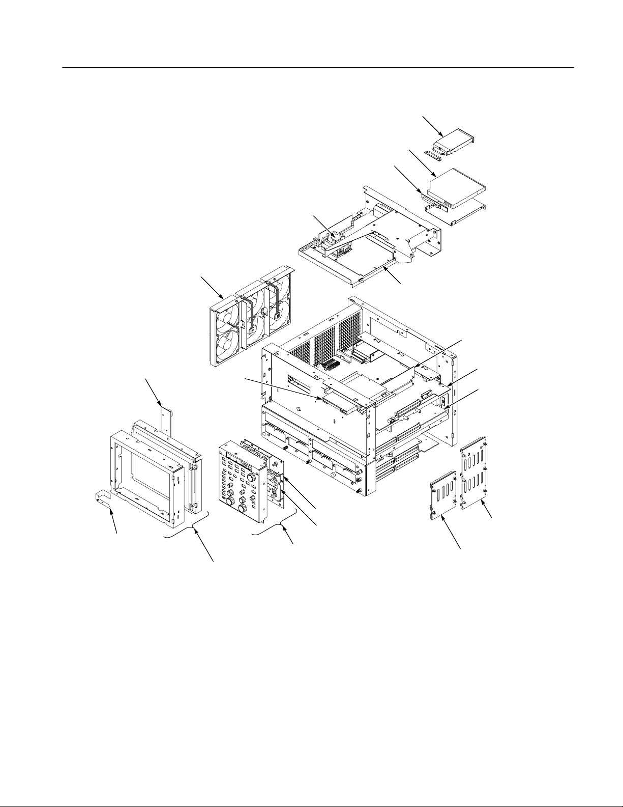
Fan assembly
Removal and Installation Procedures
Hard-drive
CD-drive
CD-drive Interface board
Microprocessor, fan and heat sink
NLX board
Riser board
Display adapter board
Standby/On switch
Figure 4--8: Internal modules
Floppy disk drive
Display module
assembly
Front panel board
Front panel keypad
Front panel assembly
Processor board
Low-voltage power
supply assembly
Rear power
distribution
board
Front power
distribution
board
CSA8000 & TDS8000 Series Instruments and Modules
4--19

Removal and Installation Procedures
Large interface
circuit board
Large module
chassis
Small module
chassis
Electrical front
end circuit board
Acquisition
circuit board
Figure 4--9: Acquisition modules
Acquisition assembly
4--20
CSA8000 & TDS8000 Series Instruments and Modules

Procedures for Modules
Removal and Installation Procedures
You should have completed the Procedures for external modules before doing
many of the procedures in this collection. The procedures found here are listed in
disassembly order:
H Front Panel assembly
H Front Panel Board
H Front Panel Keypad
H Display assembly
H Display Adapter Board
H Standby/On Switch Flex Circuit
H Floppy Disk Drive
H Hard Disk Drive
H CD Drive
H Front and Rear Power Distribution Boards
H Low-Voltage Power Supply
H NLX Board
H Microprocessor
H PC Processor Board
H Fan assembly
H Acquisition assembly
H Large Module Interface Board
H Module Slot Doors
H Electrical Modules
H Optical Modules
H 80A00 and 82A00 Series Modules
Front Panel Assembly
CSA8000 & TDS8000 Series Instruments and Modules
1. Locate module to be removed: Locate the Front Panel assembly Figure 4--10,
page 4--22. Additional modules to be removed:
H Trim (Front panel)
4--21

Removal and Installation Procedures
2. Remove the Front Panel assembly: See Figure 4--10, page 4--22.
3. Orient the instrument: Set the instrument so its bottom is down on the work
surface and its front panel is facing you.
a. Remove the six T-15 Torxdrive screws that secure the Front panel
assembly to the front chassis.
b. Grasp the top of Front Panel assembly and pull forward to allow access
to the ribbon cable connector on the front panel board.
4. Reinstallation: Do in reverse steps a through d to reinstall the front panel
Floppy disk
support tab (2)
Chassis
slot (2)
c. Use the
1
@8inch flat-bladed screwdriver to carefully lift J1 cable
connector lock up to disconnect J1 flex cable from the display module
assembly. See Figure 4--11, page 4--23. Note the connector’s pin 1 index
mark and the black stripe on the cable for later reassembly.
d. Pull the Front Panel assembly forward and remove from the instrument.
assembly.
4--22
J1 ribbon cable
Front panel
assembly
Front panel square
opening (2)
T--15 Torxdrive
screw (6)
Figure 4--10: Front panel assembly removal
CSA8000 & TDS8000 Series Instruments and Modules

Screwdriver
Removal and Installation Procedures
Black stripe
toward connector
Screwdriver
Front Panel Board
Figure 4--11: J1 flex cable connector removal
1. Locate module to be removed: Locate the Front Panel assembly Figure 4--10,
page 4--22. Additional modules to be removed:
H Front Panel Knobs
H Trim (front panel)
H Front Panel assembly
2. Remove the Front Panel board: See Figure 4--12, page 4--24.
a. Remove the eight T-15 Torxdrive screws that secure the Front panel
board to the Front panel assembly.
b. Pry the board up off the alignment studs. Place a flat bladed screwdriver
in the pry point access holes to pry the board up from the assembly.
c. Remove the board from the assembly.
3. Reinstallation: Do in reverse steps a through c to reinstall the front panel
board.
CSA8000 & TDS8000 Series Instruments and Modules
4--23

Removal and Installation Procedures
Front Panel Keypad
1. Locate module to be removed: Locate the Front Panel assembly Figure 4--10,
page 4--22. Additional modules to be removed:
H Front Panel Knobs
H Trim (front panel)
H Front Panel assembly
H Front Panel Board
2. Remove the Front Panel keypad: See Figure 4--12, page 4--24.
a. Pull on each of the keypad support guides to separate the keypad from
the Front panel board. Use a pair of tweezers or equivalent tool to pull
the keypad support guides.
b. Remove the keypad from the front panel board.
Front panel board
Keypad support
guide (9)
T-15 Torxdrive
screw (8)
Keypad
Alignment
stud
Pry point
access hole
Pry point access hole
Figure 4--12: Front panel board and keyboard removal
4--24
CSA8000 & TDS8000 Series Instruments and Modules

Removal and Installation Procedures
CAUTION. When removing or installing the keypad, make sure you do not touch
the switch contact with your fingers. The oils in your fingers will degrade or
damage the switch contacts. To help prevent damage to the keypad use cotton
gloves when removing or installing the keyboard pad.
3. Reinstallation: Do in reverse steps to reinstall the Keypad, front panel board,
and the front panel assembly. Then see the following instructions:
a. Make sure the keypad is aligned properly on the Front Panel board.
b. Make sure the ribbon cable is routed correctly when installing the Front
Panel into the chassis.
c. Insert the two floppy disk support tabs into the front panel square
openings. Both left front panel tabs must go into the chassis slots. See
Figure 4--10, page 4--22.
Display Assembly
1. Locate module to be removed: Locate the Display assembly, Figure 4--13,
page 4--26. Additional modules to be removed:
H Trim (front panel and top)
2. Orient the instrument: Set the instrument so its bottom is down on the work
surface and its front panel is facing you.
CAUTION. To avoid damage to the front panel Standby/On switch assembly, do
not set the Display module assembly on a work surface. Sliding the instrument
over the edge of the work surface could break off the Standby/On switch
assembly.
3. Remove the Display assembly: See Figure 4--13, page 4--26.
a. Remove the four T-15 Torxdrive screws that secure the Display assembly
to the chassis.
b. Grasp the top edge of the Display assembly and pull forward far enough
to allow access to the flex cable connector.
c. Disconnect J8 flex cable from the display assembly. Remove the display
module assembly from the instrument. See Figure 4--13, page 4--26.
CSA8000 & TDS8000 Series Instruments and Modules
4--25

Removal and Installation Procedures
T-15 Torxdrive
screw (4)
J8 flex cable
Display
assembly
Figure 4--13: Display removal
4. Remove the Touch panel from the Display assembly: See Figures 4--14
and 4--15, pages 4--27 and 4--28.
CAUTION. To prevent degradation of the display sharpness, this procedure must
be performed in a dust free environment. The service technician should wear
cotton gloves to prevent finger oils from contaminating all surfaces of the display
glass.
a. Disconnect J1, J9 and J10 cables from the Display Adapter circuit board.
b. Separate the assembly by carefully prying the Touch panel (outer)
assembly from the Display (inner) assembly. Insert a flat-bladed
screwdriver in the access notches to push out on the Touch panel
assembly.
4--26
CSA8000 & TDS8000 Series Instruments and Modules

Access notches
(top and bottom)
Removal and Installation Procedures
Display Adapter Board
Touch panel
LCD module
Figure 4--14: Touch panel and LCD assembly removal
5. Reinstallation: Do in reverse steps 1 through 5 to reinstall the Display
assembly.
1. Locate module to be removed: Locate the display adapter board in the locator
diagram Internal Modules, Figure 4--7, page 4--18. Additional modules to be
removed:
H Trim (front panel and top)
H Display assembly
2. Remove the Display Adapter Board: See Figures 4--15 and 4--16, page 4--28.
a. Disconnect J11, J1, J7, J8, and J9 cables from the Display Adapter board.
b. Slide the clip off the connector (at J10).
c. Disconnect J10 cable from the Display Adapter board.
d. Remove the two T-15 Torxdrive screws that secure the Display Adapter
circuit board to the Display assembly. Remove the Display Adapter from
the assembly.
3. Reinstallation: Do in reverse steps 2a through 2d to reinstall the board.
CSA8000 & TDS8000 Series Instruments and Modules
4--27

Removal and Installation Procedures
Display module
J7
J10
J1
J9
Display
adaptor board
Back view
Figure 4--15: Display adaptor board removal
Slide the clip
over connector
T--15
Torxdri v e
screw (2)
J8
J1
J10
Clip to secure
connector as
shown
4--28
Figure 4--16: Connector clip assembly
CSA8000 & TDS8000 Series Instruments and Modules

Removal and Installation Procedures
Standby/On Switch Flex
Circuit Removal
1. Locate module to be removed: Locate the Standby/On Switch flex circuit in
the locator diagram Internal Modules, Figure 4--8, page 4--19. Additional
modules to be removed:
H Trim (front panel and top)
H Display assembly
2. Orient the oscilloscope: Set the oscilloscope so its bottom is down on the
work surface and its front is facing you.
3. Remove the Standby/On Switch flex circuit: See F igure 4--17, page 4--30.
a. Peel the Standby/On switch flex circuit away from the front of the
display assembly.
b. Disconnect the flex circuit from J9 on the Display Adapter circuit board.
c. Grasp the flex circuit and pull it out of the Display assembly.
4. Reinstallation: Do following procedure to reinstall the Standby/On Switch.
a. Remove the protective backing on the Standby/On switch flex circuit.
b. Slide the connector end of the Standby/On switch flex circuit through the
slot in the Display assembly. Make sure the flex circuit connector aligns
with J9 on the Display Adapter circuit board.
c. Align the holes in the flex circuit to the two index posts on the front side
of the Display assembly.
d. Firmly press the flex circuit to the Display assembly chassis surface.
CSA8000 & TDS8000 Series Instruments and Modules
4--29

Removal and Installation Procedures
Standby/On switch
Display
assembly
flex circuit
Front view
Display adaptor board
Standby/On switch
flex circuit
J9
Back view
Figure 4--17: Standby/On switch flex circuit removal
4--30
CSA8000 & TDS8000 Series Instruments and Modules

Removal and Installation Procedures
Floppy Disk Drive
1. Locate modules to be removed: Locate the Floppy Disk Drive in the locator
diagram Internal Modules, Figure 4--8, page 4--19. Additional modules to be
removed:
H Trim (front panel and top)
H Front Panel assembly
H Display assembly
2. Remove the floppy disk drive: Use Figure 4--18, page 4--31 as a guide.
A #0 phillips screwdriver is required for this procedure.
3. Orient the instrument: Set the instrument so its bottom is down on the work
surface and its front panel is facing you.
a. Remove the two small phillips screws that secure floppy disk drive
assembly to the bracket. Use the access hole located on the outer chassis
to remove one of the small phillips screws.
b. Slide the floppy drive out toward the front of the instrument far enough
to allow you to disconnect the ribbon cable connector.
c. Remove the floppy drive from the instrument.
4. Reinstallation: Do in reverse steps a through c to reinstall the floppy disk
drive.
Ribbon
Floppy drive
Small phillips screw (2)
Figure 4--18: Floppy disk drive removal
CSA8000 & TDS8000 Series Instruments and Modules
cable
Access
hole (2)
4--31

Removal and Installation Procedures
Hard Disk Drive
1. Locate module to be removed: Locate the Hard Disk Drive in the locator
diagram Internal Modules, Figure 4--8, page 4--19.
CAUTION. Do not remove the replaceable hard disk drive when the mainframe is
powered on.
The replaceable hard disk drive may be permanently damaged if it is removed
while the mainframe is powered on.
Always power down the mainframe before removing the replaceable hard disk
drive.
2. Orient the instrument: Set the instrument so its bottom is down on the work
surface and its rear panel is facing you.
3. Remove the hard disk drive: See Figure 4--19, page 4--33.
a. Verify that the chassis is powered down.
b. Push the hard disk drive cover in and the hard drive will disconnect from
the latch.
c. Grasp the hard disk drive assembly and slide it out of the instrument.
4. Reinstallation: Do in reverse steps a and b to reinstall the hard disk drive
assembly. The hard disk drive will push in to lock and push in again to
unlock.
4--32
CSA8000 & TDS8000 Series Instruments and Modules

Depress
the latch
Remove the
hard disk drive
Removal and Installation Procedures
Figure 4--19: Hard drive disk removal
5. Remove the hard disk drive from the cartridge: See Figure 4-- 20, page 4--33.
a. Remove the four #0 phillips screws that fasten the hard disk drive to the
cartridge.
b. Carefully remove the hard disk drive from the cartridge, and remove the
cable assembly from the connector on the hard disk drive.
Remove 4 screws
Figure 4--20: Removing the hard disk drive from the cartridge
CSA8000 & TDS8000 Series Instruments and Modules
4--33

Removal and Installation Procedures
CD Drive
1. Locate module to be removed: Locate the CD Drive in the locator diagram
Internal Modules, Figure 4--8, page 4--19. Additional modules to be
removed:
H Trim (all)
H Bottom cover
H Left and Right covers
2. Remove the CD Drive assembly: See Figure 4--21, page 4--35.
3. Orient the instrument: Set the instrument so its bottom is down on the work
surface and its rear panel is facing you.
a. Remove the two T-15 Torxdrive screws that secure CD Drive assembly
to the rear chassis.
b. Disconnect the CD Drive ribbon cable J230, from Riser board.
c. Slide the CD Drive assembly (with the cable attached) toward the rear of
the chassis and remove it from the instrument.
4. Remove the CD Drive bracket and Rom interface board: See Figure 4--21,
page 4--35.
a. Remove the four #0 phillips screws that secure the bracket to the CD
Drive. Remove the CD Drive from the bracket.
b. Remove the Interface board from the CD Drive by pulling the Interface
board straight back until they separate.
5. Reinstallation: Do in reverse steps 3 and 4 to reinstall the CD Drive
assembly.
4--34
CSA8000 & TDS8000 Series Instruments and Modules

Disconnect
J230 CD drive
ribbon cable
CD drive
interface board
CD drive
ribbon cable
Removal and Installation Procedures
CD drive
#0 Phillips
screw (4)
CD drive bracket
T--15 Torxdrive
screw (2)
Figure 4--21: CD drive and bracket removal
Fan Assembly Removal
1. Locate module to be removed: Locate the Fan assembly in the locator
diagram Internal Modules, Figure 4--8, page 4--19. Additional modules to be
removed:
H Trim (all)
H Bottom cover
H Left and Right covers
2. Orient the instrument: Set the instrument so its bottom is down on the work
surface and its left side is facing you.
CSA8000 & TDS8000 Series Instruments and Modules
4--35

Removal and Installation Procedures
3. Remove the fan assembly: See Figure 4--22, page 4--36.
CAUTION. Take care when handling the fan assembly, the fan blades are brittle
and can be easily damaged.
4. Reinstallation: Do in reverse steps a through c to reinstall the fan assembly.
a. Disconnect the fan from processor/display board: Disconnect the fan’s
two power cables J130 and J170 located on the processor board.
b. Remove the two T-15 Torxdrive screws securing the fan assembly to the
top main chassis.
c. Lift the fan assembly up and out from the chassis.
Disconnect
from J170
Disconnect
from J130
4--36
Figure 4--22: Fan assembly removal
CSA8000 & TDS8000 Series Instruments and Modules
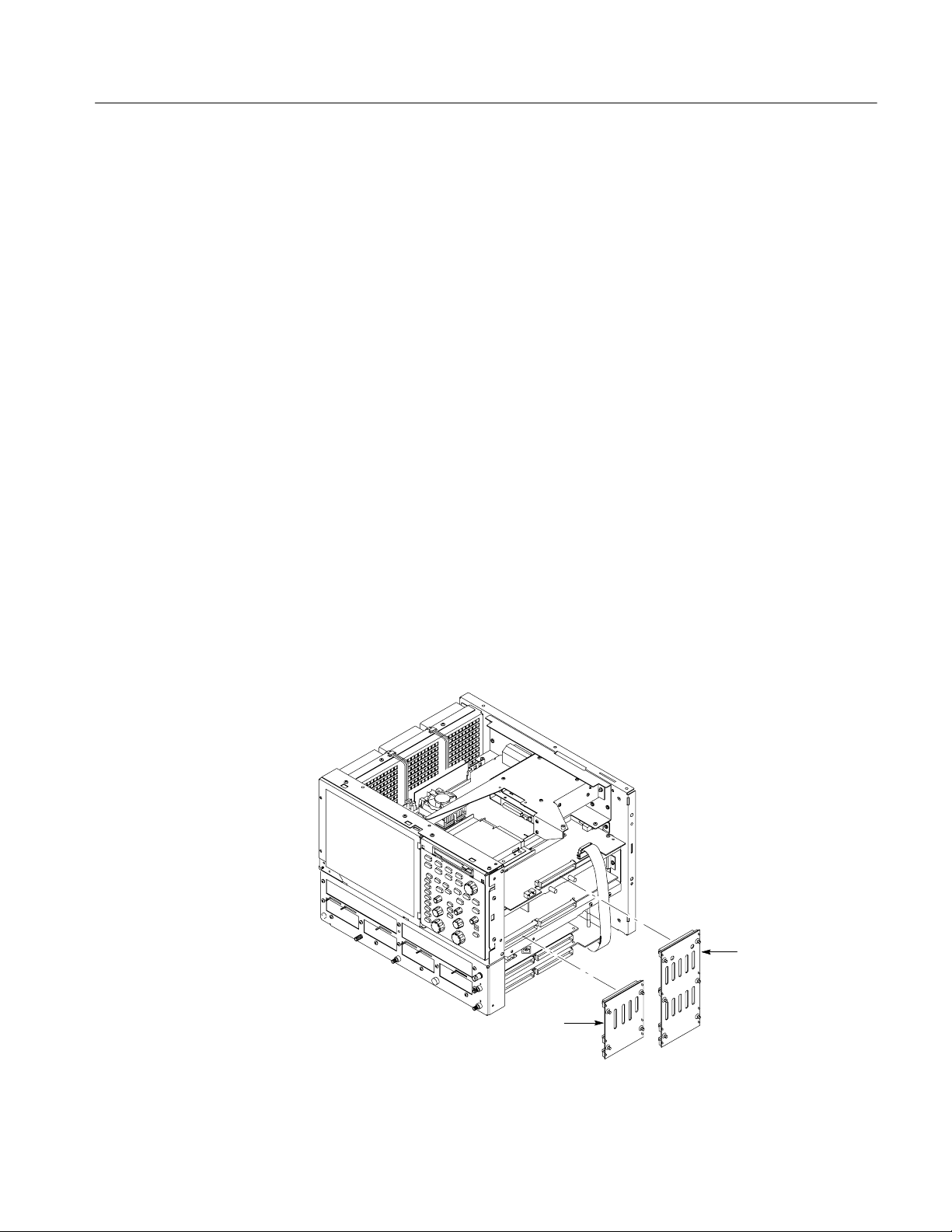
Removal and Installation Procedures
Front and Rear Power
Distribution Boards
1. Assemble equipment and locate modules to be removed: Find the modules to
be removed in the locator diagram Internal Modules, Figure 4--8, page 4--19.
Additional modules to be removed:
H Trim (all)
H Bottom cover
H Left and Right covers
2. Orient the instrument: Set the instrument so its left side is down on the work
surface and its right side is facing you.
3. Remove the Front power distribution board: See Figure 4--23, page 4--37.
a. Grasp the Front power distribution board and pull it out from the
instrument to disconnect it from the following connectors; J2 Power
supply board, J102 Electrical front-end board, and J202 Acquisition
board.
b. Remove the Rear power distribution board: Grasp the Rear Power
Distribution board and pull it out from the instrument to disconnect it
from the following connectors; J201 Processor board, J1 Power supply
board, J301 Electrical front-end board, and J102 Acquisition board.
4. Reinstallation: Do in reverse steps a and b to reinstall the front and rear
power distribution circuit boards.
Rear power
distribution
circuit board
Front power
distribution
circuit board
Figure 4--23: Front and rear power distribution board removal
CSA8000 & TDS8000 Series Instruments and Modules
4--37

Removal and Installation Procedures
Low-Voltage Power
Supply
1. Assemble equipment and locate modules to be removed: Locate the modules
to be removed in the locator diagram Internal Modules, Figure 4--8,
page 4--19. Additional modules to be removed:
NOTE. In addition to this topic, see Checking the Power Supply Voltages on
page 4--74 in the Troubleshooting section.
H Trim (all)
H Bottom cover
H Left and Right covers
H Front and Power rear distribution boards
2. Orient theinstrument: Set the instrument so its bottom is down on the work
surface and its right-side is facing you.
3. Remove the low-voltage power supply: See Figure 4--24, page 4--39.
a. Disconnect J930 ribbon cable connector from the PC processor board.
b. Remove the two T-15 Torxdrive screws securing the low-voltage power
supply to the right-side chassis support.
c. Remove the three T-15 Torxdrive screws securing the low-voltage power
supply to rear chassis.
d. Grasp the low-voltage power supply and carefully slide the assembly out
of the mainframe.
4. Reinstallation: Do in reverse steps a through c to reinstall the low-voltage
power supply.
4--38
CSA8000 & TDS8000 Series Instruments and Modules

Removal and Installation Procedures
T-15 Torxdrive screw (3)
Low-voltage power supply
T-15 Torxdrive screw (2)
Figure 4--24: Low-voltage power supply removal
CSA8000 & TDS8000 Series Instruments and Modules
4--39

Removal and Installation Procedures
NLX Board
1. Locate module to be removed: Locate the NLX Board in the locator diagram
Internal Modules, Figure 4--8, page 4--19. Additional modules to be
removed:
H Trim (all)
H Bottom cover
H Left and Right covers
2. Remove the NLX Board assembly: See Figure 4--25, page 4--41.
3. Orient the instrument: Set the instrument so its bottom is down on the work
surface and its top panel is facing you.
a. Remove the two T-15 Torxdrive screws that secure the floppy disk drive
assembly into the front chassis.
b. Slide the floppy drive assembly, with cable attached, out toward the rear
of the instrument. Place floppy drive assembly on top of the hard/CD
drive bracket.
c. Remove the five T-15 Torxdrive screws that secure NLX board assembly
to the chassis.
d. Remove the five T-15 Torxdrive screws that secure NLX board assembly
to the rear chassis.
e. Grasp the front edge of the NLX board assembly and pull up on the
assembly to disconnect the Riser Adapter from the PC Processor board’s
edge connector.
f. Remove the NLX board assembly from the instrument.
4--40
CSA8000 & TDS8000 Series Instruments and Modules

Place floppy drive assembly on
top of hard/CD drive bracket
NLX board
assembly
Riser adapter
Leave floppy drive
cable attached
Removal and Installation Procedures
Hard/CD drive
bracket
board
Remove floppy
drive assembly
from front chassis
Processor board
edge connector
Figure 4--25: NLX assembly removal
4. Remove the Riser Adapter and NLX boards: See Figure 4--26, page 4--42.
a. Remove the two T-15 Torxdrive screws that secure Riser Adapter board
to the NLX support bracket.
b. Disconnect the ribbon cable connectors from the floppy drive, hard drive
and CD drive.
CSA8000 & TDS8000 Series Instruments and Modules
4--41

Removal and Installation Procedures
5. Reinstallation: Do in reverse steps 3 and 4 to reinstall the NLX board.
c. Remove the floppy drive assembly from the NLX board assembly.
d. Grasp the Riser board and pull it straight out to disconnect J510 edge
card connector from the NLX board. Remove the Riser Adapter board
from the NLX board assembly.
e. Remove the four T-15 Torxdrive screws that secure NLX board to the
NLX support bracket.
f. Remove the six 3/16 nut posts that secure the three connectors to the rear
of the support bracket. Then remove the NLX board from the support
bracket.
g. Remove the NLX board from the support bracket.
.
Riser adapter
T--15 Torx
screw (2)
Hard drive cable
CD drive cable
connector
T--15 Torx screw (4)
Floppy
drive cable
board
connector
NLX board
J510
Nut
post (6)
4--42
NLX support
bracket
Figure 4--26: Riser adapter and NLX board removal
CSA8000 & TDS8000 Series Instruments and Modules

Removal and Installation Procedures
Microprocessor
1. Locate module to be removed: Locate the Front Panel board in the locator
diagram Internal Modules, Figure 4--8, page 4--19. Additional modules to be
removed:
H Trim
H Bottom cover
H Left and Right covers
CAUTION. The microprocessor is susceptible to static-discharge damage. Service
this component only in a static-free environment. Observe standard handling
precautions for static-sensitive devices while servicing the chassis. Always wear
a grounded wrist and foot straps while servicing the microprocessor, NLX or
processor boards.
2. Remove the microprocessor: See Figure 4--27, page 4--44.
a. Disconnect the fan power cable J401 from the NLX board.
b. Push down and pull out on the holding bracket located nearest to the
outer edge of the circuit board.
c. Pull out and unlatch the remaining bracket. Lift the fan/heatsink
assembly out from the microprocessor.
d. Lift the microprocessor socket locking lever upward. Remove the
microprocessor.
3. Reinstallation: To reinstall the microprocessor to the NLX board as follows:
a. Install the microprocessor in the socket.
b. Lower the socket locking lever.
c. Make sure the fan/heatsink assembly is positioned with the fan cable
toward the outer edge of the circuit board.
d. Place the fan/heatsink assembly on the microprocessor to allow you to
latch the bracket to the tab that is nearest to the center of the circuit
board.
e. Set the remaining edge of the fan/heatsink down on the microprocessor
and fasten the remaining bracket to the assembly.
f. Connect the fan power cable J401 from the NLX board.
CSA8000 & TDS8000 Series Instruments and Modules
4--43

Removal and Installation Procedures
and pull out to
release clamp
Fan and heatsink
Microprocessor
Push down
Locking lever
Push down
and pull out to
release clamp
J401 power cable
Figure 4--27: Microprocessor removal
NLX board
4--44
CSA8000 & TDS8000 Series Instruments and Modules

Removal and Installation Procedures
PC Processor Board
1. Locate module to be removed: Locate the PC Processor Board assembly in
the locator diagram Internal Modules, Figure 4--8, page 4--19. Remove the
following in this order:
H Trim (all)
H Bottom cover
H Left and Right covers
H Hard Disk and CD Drive
H Floppy Disk Drive
H NLX Board
H Front and Rear Power Distribution Boards
2. Orient the instrument: Set the instrument so its bottom is down on the work
surface and its top panel is facing you.
3. Remove the PC Processor board assembly: See Figure 4--28, page 4--46.
a. Disconnect J190 and J691 ribbon cables from the PC processor board.
b. Remove the nine T-15 Torxdrive screws securing the PC processor board
to the chassis support.
c. Remove the five T-15 Torxdrive screws securing the PC processor board
assembly to the rear chassis.
4. Remove the PC Processor Board: See Figure 4--28, page 4--46.
a. Remove the two
3
/16nut posts that secure the RS--232 connector to the
rear of the support bracket.
b. Remove the two
5
/16nut posts that secure the sub-D connector to the rear
of the support bracket.
c. Remove the two phillips screws that secure the PCMCIA (Personal card,
memory card interface adapter) to the pc processor board. Remove the
PCMCIA from the PC processor board.
d. Disconnect J930 ribbon cable connector from the PC processor board.
e. Then remove the PC processor board from the instrument.
5. Reinstallation: Do in reverse steps 3 and 4 to reinstall the PC processor
assembly.
CSA8000 & TDS8000 Series Instruments and Modules
4--45

Removal and Installation Procedures
T--15 Torx
screw (9)
PC processor
board
J691 J690
J930
J190
Phillips screw (2)
Support
bracket
3/16 Nut post (2)
5/16 Nut post (2)
4--46
Chassis support
Disconnect
from J930
Figure 4--28: Processor board removal
CSA8000 & TDS8000 Series Instruments and Modules
 Loading...