

Page 1

Technical Reference
CSA8000 Series Communications Signal Analyzers
TDS8000 Series Digital Sampling Oscilloscopes
Specifications and Performance Verification
071-1745-02
Warning
The servicing instructions are for use by qualified
personnel only. To avoid personal injury, do not
perform any servicing unless you are qualified to
do so. Refer to all safety summaries prior to
performing service.
www.tektronix.com
Page 2

Copyright © Tektronix. All rights reserved. Licensed software products are owned by Tektronix or its subsidiaries or
suppliers, and are protected by national copyright la ws and international treaty provisions.
Tektronix products are covered by U.S. and foreign patents, issued and pending. Information in this publication supercedes
that in all previously published material. Spec ifications and price change privileges reserved.
TEKTRONIX, TEK and TekProbe are registered trademarks of Tektronix, Inc.
Contacting Tektronix
Tektronix, Inc.
14200 SW Karl Braun Drive
P.O. Box 500
Beaverton, OR 97077
USA
For product information, sales, service, and technical support:
H In North America, call 1-800-833-9200.
H Worldwide, visit www.tektronix.com to find contacts in your area.
Page 3

Table of Contents
Specifications
General Safety Summary vii...................................
Service Safety Summary ix....................................
Preface xi...................................................
Manual Structure xi................................................
Manual Conventions xi..............................................
Related Documentation xii...........................................
System Specifications 1--1.......................................
Certifications (CSA/TDS8000, CSA/TDS8000B) 1--16.......................
Certifications (CSA/TDS8200) 1--18.....................................
80E00 Electrical Sampling Modules Specifications 1--21..............
80C00 Optical Sampling Modules Specifications 1--31................
80A01 Trigger Prescale Preamplifier Module S pecifications 1--71......
80A02 EOS/ESD Protection Module Specifications 1--73..............
80A05 Electrical Clock Recovery Module Specifications 1--75.........
80A06 PatternSync Trigger Module Specifications 1--79..............
Performance Verification
Performance Verification Procedures 2--1.........................
Brief Procedures 2--3...........................................
Perform the Diagnostics 2--3..........................................
Perform the Compensation 2--5........................................
Perform the Functional Tests 2--7.......................................
Perform the Hardware and Operating System Tests
Performance Tests 2--27.........................................
Prerequisites 2--28....................................................
Equipment Required 2--29..............................................
CSA8000/TDS8000 Series Test Records 2--32..............................
CSA8000/TDS8000 Main-Instrument Test Record 2--33......................
CSA8000B/TDS8000B Main-Instrument Test Record 2--34...................
CSA8200/TDS8200 Main-Instrument and 82A04 Module Test Record 2--35......
80E00 Electrical Modules Test Record 2--37...............................
80C00 Optical Modules Test Record 2--45.................................
80A01 Electrical Clock Recovery Module Test Record 2--73..................
Verify Electrical Input Channels 2--7.................................
Verify Optical Input Channels 2--10...................................
Verify the Time Bases Work 2--13....................................
Perform Gated Trigger Test 2--17.....................................
Checking the Cooling Fan Operation 2--23.............................
(Microsoft Windows 98 OS Only) 2--24...............................
QA+Win32 2--24.................................................
Checking the Hardware and Operating System 2--25.....................
CSA8000 & TDS8000 Series Instruments and Modules Technical Reference
i
Page 4

Table of Contents
80A02 EOS/ESD Protection Module Test Record 2--75.......................
80A05 Electrical Clock Recovery Module Test Record 2--77..................
80A06 PatternSync Trigger Module Test Record 2--79.......................
Main Instrument 2--81..........................................
Prerequisites 2--81....................................................
Time Interval Accuracy, Short--Term Optimized and
Locked-to-Internal 10-MHz Reference Modes 2--82......................
External Direct Trigger Level Accuracy 2--85..............................
External Direct Trigger Sensitivity 2--87..................................
External Direct-Trigger Delay Jitter, Short-Term Optimized
and Locked-to-Internal 10-MHz Reference Modes 2--90..................
Trigger Delay Jitter, Free Run Phase Corrected Mode
(CSA/TDS8200 with 82A04 Module Only) 2--95........................
External Prescaled Trigger Delay Jitter, Short-Term Optimized Mode
and Locked-to-Internal 10-MHz Reference Mode 2--98...................
External Prescaled Trigger Sensitivity 2--101................................
DC Calibration Output 2--104............................................
Electrical Sampling Modules 2--107................................
Prerequisites 2--107....................................................
Input Impedance 2--109.................................................
DC Voltage Measurement Accuracy 2--111................................
Random Noise, Displayed 2--118.........................................
Analog Bandwidth to 50 GHz
(80E01, 80E06, 80E07, 80E08, 80E09, 80E10) 2--120.....................
Analog Bandwidth above 50 GHz (80E06 and 80E09) 2--129...................
TDR-System Reflected Rise Time (80E04, 80E08, 80E10) 2--142...............
TDR-System Step Response Aberrations (80E04) 2--145......................
TDR-System Step Response Aberrations (80E08 and 80E10) 2--151.............
Optical Sampling Modules 2--159..................................
Prerequisites 2--159....................................................
Dark Level and Vertical Equivalent Optical Noise 2--160......................
Minimum Optical Bandwidth and Reference Receiver Frequency Response 2--169..
Integrated Rise Time and Aberrations Check 2--192..........................
Clock Recovery Optical Sensitivity Range and
Recovered Clock Timing Jitter 2--198..................................
80A01 Trigger Prescale Limiting Preamplifier Module 2--209...........
Prerequisites 2--209....................................................
System Trigger Sensitivity 2--210.........................................
80A02 EOS/ESD Protection Module 2--213..........................
Prerequisites 2--213....................................................
Logic Control Threshold 2--213..........................................
80A05 Electrical Clock Recovery Module 2--215......................
Prerequisites 2--215....................................................
Clock Recovery Sensitivity Range and Recovered Clock Timing Jitter 2--215......
80A06 PatternSync Trigger Module 2--223..........................
Prerequisites 2--223....................................................
Supported Clock Rates, Minimum Input Sensitivity,
and Maximum Jitter Checks 2--223....................................
ii
CSA8000 & TDS8000 Series Instruments and Modules Technical Reference
Page 5

List of Figures
Table of Contents
Figure 2--1: Compensation dialog box 2--5.........................
Figure 2--2: Hookup for electrical functional tests 2--8...............
Figure 2--3: Channel button location 2--8..........................
Figure 2--4: Channel button location 2--11..........................
Figure 2--5: Optical channel verification 2--12.......................
Figure 2--6: Hookup for the time base tests 2--13.....................
Figure 2--7: Channel button location 2--14..........................
Figure 2--8: Main time base verification 2--15.......................
Figure 2--9: Mag time base verification 2--16........................
Figure 2--10: Hookup for the gated trigger tests 2--18.................
Figure 2--11: Channel button location 2--19.........................
Figure 2--12: Signal triggered 2--20................................
Figure 2--13: Signal not triggered (signal frozen) 2--21................
Figure 2--14: Signal not triggered (no waveform) 2--22................
Figure 2--15: Signal triggered 2--23................................
Figure 2--16: Time interval accuracy test hookup 2--82...............
Figure 2--17: External direct trigger test hookup 2--85................
Figure 2--18: External direct trigger sensitivity test hookup 2--88.......
Figure 2--19: External direct trigger jitter test hookup 2--90...........
Figure 2--20: Phase corrected trigger jitter test hookup 2--95..........
Figure 2--21: External prescaled test hookup 2--98...................
Figure 2--22: External prescaled trigger sensitivity test hookup 2--101....
Figure 2--23: DC calibration test hookup 2--105......................
Figure 2--24: Input impedance test hookup 2--109.....................
Figure 2--25: Vertical DC accuracy test hookup 2--112.................
Figure 2--26: Power-reference hookup 2--121.........................
Figure 2--27: Adapter characterization hookup 2--122.................
Figure 2--28: Measure reference signals 2--124........................
Figure 2--29: Reference signals hookup 2--126........................
Figure 2--30: SNA/Waveguide characterization 2--131.................
Figure 2--31: Power-reference characterization h ookup 2--133..........
Figure 2--32: Hookup to measure Power-in 2--134.....................
Figure 2--33: Adapter--loss hookup 2--136...........................
Figure 2--34: HF response hookup 2--138............................
Figure 2--35: TDR reflected rise time hookup 2--142...................
CSA8000 & TDS8000 Series Instruments and Modules Technical Reference
iii
Page 6

Table of Contents
Figure 2--36: TDR system step response aberrations hookup 2--145......
Figure 2--37: TDR system step response aberrations hookup 2--151......
Figure 2--38: Dark level and vertical equivalent
optical noise test hookup 2--160................................
Figure 2--39: Minimum optical bandwidth and
reference receiver frequency response hookup 2--172...............
Figure 2--40: Proper positioning of the impulse for
optimum curve download 2--176................................
Figure 2--41: Hookup for heterodyne test 2--186......................
Figure 2--42: Setup used for heterodyne sweep 2--188..................
Figure 2--43: Integrated rise time and aberrations hookup 2--193........
Figure 2--44: Clock recovery optical sensitivity range
and recovered clock timing jitter hookup 2--199...................
Figure 2--45: Display example
(clock signal not synchronized with the data rate input) 2--204......
Figure 2--46: Display example
(clock signal synchronized with the data rate input) 2--207..........
Figure 2--47: Display example (zoomed in at the crossing point) 2--208...
Figure 2--48: 80A01 test hookup 2--211..............................
Figure 2--49: 80A02 test hookup 2--214..............................
Figure 2--50: Clock recovery sensitivity range and
recovered clock timing jitter hookup 2--217.......................
Figure 2--51: Display example
(clock signal synchronized with the data rate input) 2--220..........
Figure 2--52: Display example (zoomed in at the crossing point) 2--222...
Figure 2--53: Hookup for Clock Rates, Input Sensitivity,
and Jitter Checks 2--225.......................................
Figure 2--54: Example display for Supported Clock Rates,
Minimum Input Sensitivity, and Maximum Jitter Checks 2--226.....
iv
CSA8000 & TDS8000 Series Instruments and Modules Technical Reference
Page 7

List of Tables
Table of Contents
Table 1--1: System -- Signal acquisition 1--1.......................
Table 1--2: System -- Timebase 1--3..............................
T a b l e 1 -- 3 : S y s t e m -- T r i g g e r 1 -- 5................................
T able 1--4: System -- T rigger -- Phase correction modes
(CSA/TDS8200 with 82A04 Phase Reference module) 1--9........
T a b l e 1 -- 5 : D i s p l a y 1 -- 1 0........................................
T a b l e 1 -- 6 : P o r t s 1 -- 1 0..........................................
Table 1--7: Data storage 1--12....................................
Table 1--8: Power consumption, fuses, an d cooling 1--12..............
T able 1--9: Mechanical 1--14.....................................
Table 1--10: System -- Environmental 1--14.........................
T able 1--11: Mechanical -- 82A04 Phase Reference module 1--15.......
Table 1--12: Certifications and compliances 1--16....................
Table 1--13: Certifications and compliances 1--18....................
Table 1--14: Electrical sampling modules -- Signal acquisition 1--22....
Table 1--15: Electrical sampling modules (80E04, 80E08,
and 80E10 TDR Sampling Modules) -- TDR system 1--26..........
T able 1--16: Electrical sampling modules -- Timebase system 1--28.....
Table 1--17: Electrical sampling modules -- Power consumption 1--28...
T able 1--18: Electrical sampling modules -- Mechanical 1--28..........
Table 1--19: Optical modules -- Descriptions 1--32...................
Table 1--20: Optical modules -- Acquisition 1-- 35....................
T able 1--21: Optical Power Meter 1--60............................
Table 1--22: Optical modules -- Clock recovery options
(CR, CR1, CR2, CR3, and CR4) 1--60..........................
T able 1--23: Optical modules -- Mechanical 1--68....................
Table 1--24: Optical modules -- Environmental 1--69.................
T able 1--25: Module characteristics 1--71...........................
Table 1--26: Environmental specifications 1--72.....................
T able 1--27: Mechanical specifications 1--72........................
T able 1--28: Electrical 1--73......................................
Table 1--29: Environmental and mechanical 1--74...................
T able 1--30: Module characteristics 1--75...........................
Table 1--31: Environmental specifications 1--77.....................
T able 1--32: Mechanical specifications 1--77........................
CSA8000 & TDS8000 Series Instruments and Modules Technical Reference
v
Page 8

Table of Contents
Table 1--33: Product family electromagnetic compatibility
(EMC) 1--78................................................
Table 1--34: Product family dynamics 1--78.........................
Table 1--35: Product family atmospherics 1--78......................
Table 1--36: 80A06 PatternSync trigger system 1--79.................
T able 1--37: 80A06 Mechanical characteristics 1--81..................
Table 1--38: Product family electromagnetic compatibility
(EMC) 1--82................................................
Table 1--39: Product family dynamics 1--82.........................
Table 1--40: Product family atmospherics 1--82.....................
Table 2--1: Equipment required 2--29.............................
Table 2--2: Application software version required 2--108...............
Table 2--3: DC voltage measurement accuracy 2--113.................
Table 2--4: Data for calculation of gain and linearity 2--117............
Table 2--5: Random noise limits 2--119.............................
T able 2--6: Power reference 2--121.................................
Table 2--7: DUT (device under test) reference response 1 2-- 125.........
Table 2--8: Bandwidth response (55 GHz -- 65 GHz) 2--140.............
Table 2--9: Application software version required 2--159...............
Table 2--10: Dark level and vertical equivalent
optical noise limits 2--163.....................................
Table 2--11: Minimum optical bandwidth limits 2--177................
T able 2--12: Reference r eceiver frequency response limits 2--178........
T able 2--13: Reference r eceiver frequency response limits 2--191........
Table 2--14: Minimum limits 2--196................................
T able 2--15: Aberrations 2--196....................................
Table 2--16: Clock recovery settings 2--201..........................
Table 2--17: Clock recovery settings and jitter limits 2--205............
Table 2--18: Clock recovery settings 2--218..........................
Table 2--19: Clock recovery amplitude and jitter limits 2--221..........
Table 2--20: PatternSync settings and jitter limits 2-- 227...............
vi
CSA8000 & TDS8000 Series Instruments and Modules Technical Reference
Page 9

General Safety Summary
Review the following safety precautions to avoid injury and prevent damage to
this product or any products connected to it. To avoid potential hazards, use this
product only as specified.
Only qualified personnel should perform service procedures.
While using this product, you may need to access other parts of the system. Read
the General Safety Summary in other system manuals for warnings and cautions
related to operating the system.
ToAvoidFireor
Personal Injury
Use Proper Power Cord. Use only the power cord specified for this product and
certified for the country of use. Power cord needed only in the mainframe, not
modules.
Connect and Disconnect Properly. Do not connect or disconnect probes or test
leads while they are connected to a voltage source.
Ground the Product. The mainframe is grounded through the grounding
conductor of the power cord. To avoid electric shock, the grounding conductor
must be connected to earth ground. Before making connections to the input or
output terminals of the product, ensure that the product is properly grounded.
Ground the Product. The modules are indirectly grounded through the grounding
conductor of the mainframe power cord. To avoid electric shock, the grounding
conductor must be connected to earth ground. Before making connections to the
input or output terminals of the product, ensure that the product is properly
grounded.
Observe All Terminal Ratings. To avoid fire or shock hazard, observe all ratings
and markings on the product. Consult the product manual for further ratings
information before making connections to the product.
Do not apply a potential to any terminal, including the common terminal, that
exceeds the maximum rating of that terminal.
Do Not Operate Without Covers. Do not operate this product with covers or panels
removed.
Use Proper Fuse. Use only the fuse type and rating specified for this product.
Avoid Exposed Circuitry. Do not touch exposed connections and components
when power is present.
Wear Eye Protection. Wear eye protection if exposure to high-intensity rays or
laser radiation exists.
Do Not Operate With Suspected Failures. If you suspect there is damage to this
product, have it inspected by qualified service personnel.
CSA8000 & TDS8000 Series Instruments and Modules Technical Reference
vii
Page 10
General Safety Summary
Do Not Operate in Wet/Damp Conditions.
Do Not Operate in an Explosive Atmosphere.
Keep Product Surfaces Clean and Dry.
Provide Proper Ventilation. Refer to the manual’s installation instructions for
details on installing the product so it has proper ventilation.
Symbols and Terms
Terms in this Manual. These terms may appear in this manual:
WARNING. Warning statements identify conditions or practices that could result
in injury or loss of life.
CAUTION. Caution statements identify conditions or practices that could result in
damage to this product or other property.
Terms on the Product. These terms may appear on the product:
DANGER indicates an injury hazard immediately accessible as you read the
marking.
WARNING indicates an injury hazard not immediately accessible as you read the
marking.
CAUTION indicates a hazard to property including the product.
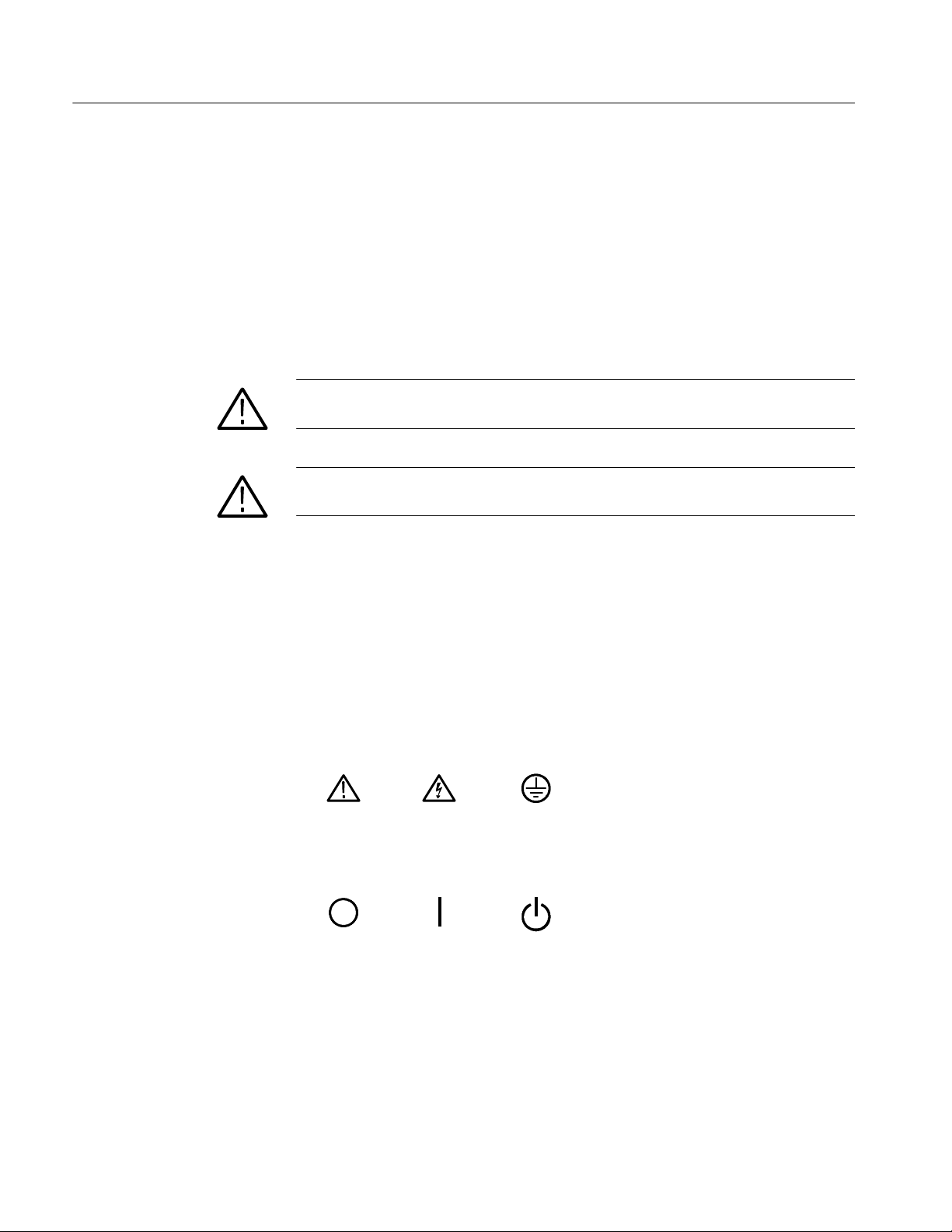
Symbols on the Product. The following symbols may appear on the product:
viii
CAUTION
Refer to Manual
Mains Disconnected
OFF (Power)
WARNING
High Voltage
Mains Connected
ON (Power)
Protective Ground
(Earth) Terminal
Standby
CSA8000 & TDS8000 Series Instruments and Modules Technical Reference
Page 11

Service Safety Summary
Only qualified personnel should perform service procedures. Read this Service
Safety Summary and the General Safety Summary before performing any service
procedures.
Do Not Service Alone. Do not perform internal service or adjustments of this
product unless another person capable of rendering first aid and resuscitation is
present.
Disconnect Power. To avoid electric shock, switch off the instrument power, then
disconnect the power cord from the mains power.
Use Care When Servicing With Power On. Dangerous voltages or currents may
exist in this product. Disconnect power, remove battery (if applicable), and
disconnect test leads before removing protective panels, soldering, or replacing
components.
To avoid electric shock, do not touch exposed connections.
CSA8000 & TDS8000 Series Instruments and Modules Technical Reference
ix
Page 12

Service Safety Summary
x
CSA8000 & TDS8000 Series Instruments and Modules Technical Reference
Page 13

Preface
Manual Structure
This manual contains the specifications and performance verification procedures
for the:
H CSA8000, CSA8000B, and CSA8200 Communications Signal Analyzers
H TDS8000, TDS8000B, and TDS8200 Digital Sampling Oscilloscopes
H Modules that install in the instruments (except the 80A03 module)
NOTE. The 80A03 instruction manual contains its own specifications and
servicing information.
Read this preface to learn how this manual is structured, what conventions it
uses, and where you can find other information related to this product.
This manual is divided into chapters, which are made up of related subordinate
topics. These topics can be cross referenced as sections.
Be sure to read the introductions to all procedures. These introductions provide
important information needed to do the service correctly, safely, and efficiently.
Manual Conventions
Modules
Safety
This manual uses certain conventions that you should become familiar with
before attempting service.
Throughout this manual, the term module appears. A module is composed of
electrical and mechanical assemblies, circuit cards, interconnecting cables, and a
user-accessible front panel. References to a module are different than references
to products such as “Sampling modules”. “Phase Reference modules”, or
“Accessory modules” which are products installed in the instrument compartments.
Symbols and terms related to safety appear in the General Safety Summary found
at the beginning of this manual.
CSA8000 & TDS8000 Series Instruments and Modules Technical Reference
xi
Page 14

Preface
Related Documentation
The following documents relate to the instruments this manual supports:
H CSA8200 and TDS8200 Quick Start User Manual. Tektronix part number
071-1482-XX. This document also contains specification changes when
using the 82A04 Phase Reference module.
H CSA8000 and TDS8000 Service Manual. Tektronix part number 071-0438-
XX.
H CSA8000 and TDS8000 Online Help. Installed with the application software
and accessed from the instrument Help menu.
H CSA8000 & TDS8000 Programmer Guide. An online document accessed
from the instrument Help menu.
H 80E01, 80E02, 80E03, 80E04, and 80E06 Electrical Sampling Modules
User Manual. Tektronix part number 071-0434-XX.
H 80E07, 80E08, 80E09, and 80E10 Electrical Sampling Remote Modules
User Manual. Tektronix part number 071-2038-XX.
H 80C00 Series Optical Sampling Modules User Manual. Tektronix part
number 071-0435-XX.
H 80A01 Trigger Prescale Limiting Preamplifier Module User Manual.
Tektronix part number 071-0873-XX.
H 80A02 EOS/ESD Protection Module Instructions. Tektronix part number
071-1317-XX
H 80A03 TekConnect Probe Interface Module Instructions. Tektronix part
number 071-1298-XX.
H 80A05 Electrical Clock Recovery Module User Manual. Tektronix part
number 071-1467-XX.
H 80A06 PatternSync Trigger Module Instructions. Tektronix part number
071-1744-XX.
H CSA8000/TDS8000 Rackmount Kit Instructions. Tektronix part number
071-0696-XX.
H TDR Z-Meas Application Online Help. Ships with this product on a separate
CD. Provides information about this TDR Impedance Measuring application
that implements the TDR calibration procedures specified by the
IPC TM-650 test method.
xii
H Fast NRZ Application Online Help. Ships with this product on a separate
CD. Provides information about this application that improves throughput
for optical eye-pattern mask testing.
CSA8000 & TDS8000 Series Instruments and Modules Technical Reference
Page 15

Specifications
Page 16

Page 17

System Specifications
NOTE. This specification is for the instrument; the specifications for the optical,
electrical, and other modules that insert in the module compartments of the
instrument front panel are included in this chapter of the manual.
This section contains the specifications for the CSA8000, CSA8000B, and
CSA8200 Communications Signal Analyzers and the TDS8000, TDS8000B, and
TDS8200 Digital Sampling Oscilloscopes.
The 82A04 Phase Reference module affects the CSA8200 and TDS8200
mainframe specifications which are documented in the mainframe specifications.
There is no separate specification section for the 82A04 module.
All specifications are guaranteed unless noted as “typical.” Typical specifications
are provided for your convenience but are not guaranteed. Specifications that are
marked with the n symbol are checked in Performance Verification chapter of
this manual.
All specifications apply to the instrument and sampling modules. unless noted
otherwise. To meet specifications, these conditions must first be met:
H The instrument must have been calibrated/adjusted at an ambient tempera-
ture between +10 _C and +40 _C.
H The instrument must have been operating continuously for 20 minutes within
the operating temperature range specified.
H The instrument must be in an environment with temperature, altitude,
humidity, and vibration with the operating limits described in these
specifications.
NOTE. “Sampling Interface” refers to both the small module compartments and
the large module compartments, unless otherwise specified.
Table 1- 1: System - Signal acquisition
Description Characteristics
Number of input channels 8 acquisition channels, maximum
Number of small sampling module
compartments
4 compartments, 2 channels per compartment, for a total of 8 channels
1
CSA8000 & TDS8000 Series Instruments and Modules Technical Reference
1- 1
Page 18

System Specifications
Table 1- 1: System - Signal acquisition (cont.)
Description Characteristics
Number of large sampling module
compartments
TDS/CSA8000, TDS/CSA8000B 2 compartments, for a total of 2 channels
TDS/CSA8200 2 compartments, for a total of 4 channels
Small Sampling Module Interface Tekprobe-Sampling Level 3. Hot switching is not permitted on this interface.
Large Sampling Module Interface Tekprobe-Sampling Level 3. Hot switching is not permitted on this interface.
Compartment assignments and
conflict resolution
TDS/CSA8000, TDS/CSA8000B Population of either Ch 1 or Ch 2 large compartment with any module other than one
requiring power only, displaces functionality of the Ch 1 / Ch 2 small compartment.
TDS/CSA8200 Population of the Ch 1 / Ch 2 large compartment with any module (other than one requiring
power only) displaces functionality of the Ch 1 / Ch 2 small compartment. Population of the
Ch 3 / Ch 4 large compartment with any module (other than one requiring power only)
displaces functionality of the Ch 3 / Ch 4 small compartment.
1
1
Compartment utilization
TDS/CSA8000, TDS/CSA8000B Supports the 80xxx nomenclat ed modules.
TDS/CSA8200 Supports the 80xxx and 82xxx nomenclated modules, including Phase Reference modules.
Real time accessory interface
TDS/CSA8000, TDS/CSA8000B The small slot supports TekProbe-SMA, Levels 1 and 2. No accessory support is offered on
the large slot.
Hot switching is permitted on this real time accessory interface.
TDS/CSA8200 Small and large slots supports TekProbe-SMA, Levels 1 and 2.
Hot switching is permitted on this real time accessory interface.
Vertical sensitivity ranges 10 mV to 1 V full scale at TekProbe-Sampling interface. May be scaled according to
sampling module scaling characteristics.
Vertical operating range --1.6 V to +1. 6 V at TekProbe-Sampling interface. May be scaled according to sampling
module scaling characteristics.
Vertical number of digitized bits 14 bits at TekProbe-Sampling interface
Offset capabilities Open loop offset mode is supported at TekProbe-Sampling interface.
Offset range ±1.6 V at TekProbe-Sampling interface. May be scaled according to sampling module
offset and scaling characteristics.
Offset resolution 14 bits over ±1.8 V at TekProbe-Sampling interface.
1
Total channels ≤ 8.
1- 2
CSA8000 & TDS8000 Series Instruments and Modules Technical Reference
Page 19

System Specifications
Table 1- 2: System - Timebase
Description Characteristics
Horizontal modes
All mainframes Short term jitter optimized and Locked to 10 MHz Reference are supported. The 10 MHz
reference may be internal or external.
TDS/CSA8200 with 82A04 Free Run and Triggered Modes are supported.
Sampling rate
TDS/CSA8000, TDS/CSA8000B,
and TDS/CSA8200 (regular modes)
DC -- 200 kHz maximum, dictated by trigger rate and actual holdoff setting. If trigger rate is
less than the maximum, or the requested holdoff exceeds the minimum, the trigger rate
and/or holdoff will dictate the sampling rate.
TDS/CSA8200 with 82A04 (phase
corrected modes)
DC -- 50 kHz maximum, one channel. If trigger rate is less than the maximum, or the
requested holdoff exceeds the minimum, the trigger rate and / or holdoff will dictate
sampling rate.
Record length
1
20, 50, 100, 250, 500, 1000, 2000 and 4000 samples.
Horizontal scale range
Software version 1.0 to 2.0 1 ps/div to 5 ms/div in 1, 2, 5 steps or 1 ps increments. Maximum record lengths apply at
certain ranges per table. For record lengths greater than 500, the horizontal scale is limited
as shown in the table below.
Scale set to an integer multiple of: Maximum record length
1 ps/div 1000
2 ps/div 2000
4 ps/div 4000
Software version 2.1 and above 100 fs/div to 5 ms/div in 1, 2, 5 steps or 100 fs increments are supported. Maximum record
lengths apply at certain ranges per table. For record lengths greater than 1000, the
horizontal scale is limited as shown in the table below.
Scale set to an integer multiple of: Maximum record length
100 fs/div 1000
200 fs/div 2000
400 fs/div 4000
Horizontal position range
All mainframes 50 ms maximum.
TDS/CSA8200 with 82A04 Range is det ermined by the following formula where (f) equals the frequency of the
reference clock.
1
16
× 2
f
Horizontal resolution
Software version 1.0 to 2.0 10 fs minimum
Software version 2.1 and above 1 fs minimum
CSA8000 & TDS8000 Series Instruments and Modules Technical Reference
1- 3
Page 20

System Specifications
j
p
ical)
Table 1- 2: System - Timebase (cont.)
Description Characteristics
Horizontal position setting resolution
Software version 1.0 to 1.2 1 ps minimum
Software version 1.3 to 2.0 100 fs minimum
Software version 2.1 and above 10 fs minimum
n Time interval accuracy, short term
jitter optimized mode
Strobe placement accuracy for a given horizontal interval and position on same strobe line
per table bel ow. (Contribution from 80E04 sampling module is included in speci fication.)
1 ps + 1% of interval, horizontal scale ≤ 20 ps/div, rightmost point of measurement interval
<200 ns
8 ps + 0.1% of interval, horizontal scale ≥ 21 ps/div, rightmost point of measurement
interval <200 ns (8200)
8 ps + 0.6% of interval, horizontal scale ≥ 21 ps/div, rightmost point of measurement
interval <200 ns (8000 and 8000B)
Guaranteed for all trigger rates (8200)
Guaranteed only f or ≤ 100 kHz t ri gger rate (8000 and 8000B)
Time interval accuracy, short term jitter
optimizedmode(typ
(8000 and 8000BB)
n Time interval accuracy, locked to
internal 10 MHz reference mode
Timing accuracy, free run phase
corrected mode
(Not available for TDS/ CSA8000 or
TDS/CSA8000B)
TDS/CSA8200 with 82A04 Maximum timing deviation 0.1% of phase reference signal period, typical, relative to phase
2
1 ps + 1% of interval, ≤ 20 ps/div
8 ps + 0.1% of interval, ≥ 21 ps/div for ≥ 100 kHz trigger rate
Strobe placement accuracy for a given horizontal interval and position on same strobe line
per table bel ow. Contribution from 80E04 sampling module is included in specification.
1 ps + 1% of interval, ≤ 20 ps/div
8 ps + 0.01% of interval, ≥ 21 ps/div
Guaranteed only f or ≤ 100 kHz t ri gger rate (8000 and 8000B)
Guaranteed for all trigger rates (8200)
reference signal.
Assumes that phase reference frequency has been correctly entered. Operation of phase
reference clock at frequencies requiring extended bandwidth or signal conditioning may
require an instrument option.
1- 4
CSA8000 & TDS8000 Series Instruments and Modules Technical Reference
Page 21

System Specifications
Table 1- 2: System - Timebase (cont.)
Description Characteristics
Timing accuracy, triggered phase
corrected mode
(Not available for TDS/ CSA8000 or
TDS/CSA8000B)
TDS/CSA8200 with 82A04 Maximum timing deviation relative to phase reference signal:
0.2% of phase reference signal period typical for measurements made >40 ns after
trigger event.
0.4% of phase reference signal period typical for measurements made ≤40 ns after
trigger event.
Assumes that phase reference frequency has been correctly entered.
Horizontal deskew range and
resolution
All mainframes --500 ps to +100 ns on any individual channel in 1 ps increments.
TDS/CSA8200 with 82A04 Operating in Triggered Phase Corrected modes: --500 ps to +100 ns on any individual
channel in 1 ps increments.
Operating in Free Run Phase Corrected modes: Deskew range extends over the full
clock cycle of the phase reference.
1
The total number of samples contained in a single acquired waveform record (memory length in IEEE 1057, 2.2.1).
2
80E02 sampling module is included in this specification.
Table 1- 3: System - Trigger
Description Characteristics
Trigger sources
All mainframes External Direct Edge Trigger, External Prescaled Trigger, Internal Clock Trigger, and Clock
Recovery (with appropriately equipped optical modules)
CSA/TDS8200 with 82A04 A phase reference signal may be applied to the instrument, w hen equipped with an
82A04 Phase Reference module, to provide additional phase information for signals
being acquired in Triggered Phase Corrected modes and primary phase information
for signals being acqui red in Free Run Phase Corrected modes.
Two bandwidth options are available for the 82A04 and may be required over specific
frequency ranges of operation:
The base product has an 8 GHz -- 25 GHz range of operation.
Option 60G extends the upper frequency range of operation to 60 GHz.
Auto/normal mode Normal mode: wait for tri gger
Auto mode: Trigger automati cally generated after 100 ms time-out
CSA8000 & TDS8000 Series Instruments and Modules Technical Reference
1- 5
Page 22

System Specifications
Table 1- 3: System - Trigger (cont.)
Description Characteristics
Slope + or -- select Edge + mode: Triggers on positive-slewing edge.
Edge -- mode: Triggers on negative-slewing edge.
High frequency on/off select High Frequency ON mode: Removes trigger hysteresis and improves sensitivity. Should be
used when trigger slew rate exceeds 1 V/ns.
High Frequency OFF mode: Retains trigger hysteresis and improves noise rejection at low
slew rates.
Variable trigger hold off range and
resolution
TDS/CSA8000, TDS/CSA8000B When External Prescaled Trigger mode is used, holdoff period applies to the Prescaled
TDS/CSA8200 When External Prescaled Trigger mode is used, holdoff period applies to the Prescaled
External direct trigger capabilities and
conditions
Adjustable 5 s to 50 ms in 0.5 ns i ncrements.
input divided by 8.
input divided by 16.
Direct edge triggering on signal applied to dedicated front panel connector with Holdoff,
Level Adjust, Auto/Normal, High Frequency On/Off, and Enhanced Triggering On/Off
controls.
External direct trigger specifications apply only under the condition that no other trigger
signal is applied to respective connect ors, except 82A04 Phase Reference modules.
Short term optimized mode and locked to internal 10 MHz reference specifications only
apply under the condition that there is no external 10 MHz reference applied to the front
panel connector.
External direct trigger input characteris-
1
tics
50 Ω input resistance, DC coupled only
External direct trigger input range ±1.5 V (DC + peak AC) maximum input voltage
External direct trigger maxi mum operating
trigger signal
2
1V
p-p
External direct trigger level range Adjustable between ±1.0 V
n External direct trigger sensitivity
3
100 mV, DC -- 3 GHz
External direct trigger sensitivity 50 mV typical, DC -- 4 GHz
External direct trigger level resolution 1mV
n External direct trigger level accuracy 50 mV + 0.10 x level
External direct trigger delay jitter, short
term optimized mode (typical)
CSA/TDS8000 1.0 ps RMS + 5 ppm of horizontal position
CSA/TDS8000B, CSA/TDS8200 800 fs RM S + 5 ppm of horizontal position
n External direct trigger delay jitter, short
term optimized mode
CSA/TDS8000 1.5 ps RMS + 10 ppm of horizontal position, or better
CSA/TDS8000B, CSA/TDS8200 1.0 ps RMS + 8 ppm of horizontal position, or better
1- 6
CSA8000 & TDS8000 Series Instruments and Modules Technical Reference
Page 23

Table 1- 3: System - Trigger (cont.)
/,/
Description Characteristics
External direct delay j itter, locked to
internal 10 MHz reference mode (typical)
CSA/TDS8000 1.6 ps RMS + 0.05 ppm of horizontal position
CSA/TDS8000B, CSA/TDS8200 1.6 ps RMS + 0.01 ppm of horizontal position
n External direct delay jitter, locked to
internal 10 MHz reference mode
CSA/TDS8000 2.5 ps RMS + 0.10 ppm of horizontal position, or better
CSA/TDS8000B, CSA/TDS8200 2.5 ps RMS + 0.04 ppm of horizontal position, or better
External direct trigger mi nimum pulse
width (typical)
External direct trigger met astability
(typical)
External direct trigger real time accessory
interface
External prescaled trigger capabilities and
conditions (typical)
167 ps
Zero
Tekprobe-SMA, Levels 1 and 2. Hot switching i s permit ted on this real time accessory
interface.
Prescaled triggering on signal applied to dedicated front panel connector with Holdoff,
Auto/Normal, Metastability Reject On/Off.
System Specifications
4
External prescaled trigger specifi cations apply only under the condition that no other trigger
source is applied to respective connectors.
Short term optimized mode and locked to internal 10 MHz reference specifications only
apply under the condition that there is no external 10 MHz reference applied to the front
panel connector.
External prescaled trigger input characteristics (typical)
CSA/TDS8000, CSA/TDS8000B 50 Ω AC coupled input resistance; divide-by-eight prescaler ratio, fixed level zero volts
CSA/TDS8200 50 Ω AC coupled input resistance; divide-by-sixteen prescaler ratio, fixed level zero volts
External prescaled trigger absolute
±2.5 Vpp
maximum input (typical)
n External prescaled trigger sensitivity
CSA/TDS8000, CSA/TDS8000B Frequency range Sensitivity
2GHz--3GHz 800 mV
3 GHz -- 10 GHz 600 mV
p-p
p-p
External prescaled trigger sensitivity
(typical)
CSA/TDS8000, CSA/TDS8000B Frequency range Sensitivity
10 GHz -- 12.5 GHz 1000 mV
p-p
5
n External prescaled trigger sensitivity
and usable range
CSA/TDS8200 Frequency range Sensitivity
2GHz--12.5GHz 200 mV
to 800 mV
p-p
p-p
CSA8000 & TDS8000 Series Instruments and Modules Technical Reference
1- 7
Page 24

System Specifications
Table 1- 3: System - Trigger (cont.)
Description Characteristics
External prescaled trigger delay jitter,
short term optimized mode (typical)
CSA/TDS8000 1.0 ps
CSA/TDS8000B, CSA/TDS8200 0.9 ps
n External prescaled trigger delay jitter,
short term optimized mode
CSA/TDS8000 1.5 ps
CSA/TDS8000B, CSA/TDS8200 1.3 ps
External prescaled delay jitter, locked to
internal 10 MHz reference mode (typical)
CSA/TDS8000 1.6 ps
CSA/TDS8000B, CSA/TDS8200 1.6 ps
n External prescaled delay jitt er, locked
to internal 10 MHz reference mode
CSA/TDS8000 2.5 ps
CSA/TDS8000B, CSA/TDS8200 2.5 ps
External prescaled trigger metastability
Zero
(typical)
Internal clock trigger rates Rate selectable at 25, 50, 100, and 200 kHz internally and is provided to the trigger, to the
TDR stimulus drives in t he small sam pling module interfaces, and to the Internal Clock Out
connector on the front panel.
1
The input resistance at the external direct trigger input and the maximum input voltage.
2
Maximum signal input for maintaining calibrated time base operation.
3
Section 4.10.2 in IEEE standard number 1057. The minimum signal levels required for stable edge triggering of an
acquisition.
4
Metastability Reject is not available with product software versions 2.4 and above.
5
The 80A01 accessory is designed to allow users to enhance performance.
+ 5 ppm of horizontal position
RMS
+ 5 ppm of horizontal position
RMS
+ 10 ppm of horizontal position, or better
RMS
+ 10 ppm of horizontal position, or better
RMS
+ 0.05 ppm of horizontal position
RMS
+ 0.01 ppm of horizontal position
RMS
+ 0.1 ppm of horizontal position, or better
RMS
+ 0.04 ppm of horizontal position, or better
RMS
1- 8
CSA8000 & TDS8000 Series Instruments and Modules Technical Reference
Page 25

System Specifications
Table 1- 4: System - Trigger - Phase correction modes (CSA/TDS8200 with 82A04 Phase Reference module)
Description Characteristics
Note. The specifications in this table apply to a CSA8200 or TDS8200 mainframe equipped with an 82A04 Phase Reference module.
The CSA8000, TDS8000, CSA8000B, and TDS8000B mainframes do not support the use of the 82A04 Phase Reference module.
Phase correction capabilities and
conditions
A phase reference signal may be applied to a TDS8200 / CSA8200 equipped with the
82A04 Phase Reference module, to provide additional phase information for signals
being acquired in Triggered Phase Corrected modes and primary phase information
for signals being acqui red in Free Run Phase Corrected modes. For Phase Corrected
Triggered modes, the phase correction functionality overlays the functionality of the
basic trigger operation, al though restrictions may be imposed.
Number of phase reference module
inputs
One per 82A04 module. Up to three 82A04 modules may be inserted in the small
compartments of the TDS8200 / CSA8200 and characterized to operate with one or
more vertical sampling module(s); only one phase correction module at a time can be
used.
Phase reference input connector Precision 1.85 mm female connector (V)
A 2.4 mm m ale to 2.92 mm (K) female adapter is provided as a standard accessory to
provide connection to 3.5 mm compatible male connectors.
Phase reference module input
50 Ω AC coupled through 5 pF
characteristics (typical)
Phase reference module input
2V
(offset ±1000 mV)
p-p
dynamic range (nonclipping)
Phase reference module input
±3 V maximum
maximum nondestruct range
Phase reference module input signal
600 mV
p-p
to 1.8 V
to achieve typical specified jitter performance
p-p
level
Phase reference mode jitter (typical) Triggered and Free Run Phase Corrected Modes, 8 GHz -- 60 GHz clock,
600 mV -- 1.8 V
input: 200 fs
p-p
RMS
or better.
Triggered and Free Run Phase Corrected Modes, 2 GHz -- 8 GHz sine wave clock,
600 mV -- 1.8V
input: 280 fs
p-p
or better. The jitter increase between 8 GHz and
RMS
2 GHz is roughly inverse proportion to clock frequency.
Operation of phase reference clock at frequencies requiring extended bandwidth or
signal conditioning may require an optional filter accessory.
Phase reference module compensation temperature range (typical )
±5 _C where compensation was performed. If compartment is changed on
mainframe, or if sampling module extender is employed, or length of sampling module
extender is changed, the Phase Reference module must be recompensated.
n Phase reference module input
operating frequency
With 82A04 8 GHz to 25 GHz
With 82A04-60 G 8 GHz to 60 GHz
Phase reference module input
operating frequency (typical)
CSA8000 & TDS8000 Series Instruments and Modules Technical Reference
1- 9
Page 26

System Specifications
Table 1- 4: System - Trigger - Phase correction modes (CSA/TDS8200 with 82A04 Phase Reference module) (cont.)
Description Characteristics
With 82A04 2 GHz to 25 GHz usable range
Operation below 8 GHz requires the use of external filters, as follows:
2 GHz -- 4 GHz: requires 2.2 GHz peaked lowpass filter kit, Tektronix part
number 020-2566-00.
4 GHz -- 6 GHz: requires 4 GHz lowpass filter kit, Tektronix kit part number
020-2567-00.
6 GHz -- 10 GHz: requires 6 GHz filter lowpass filter kit, Tektronix kit part num ber
020-2568-00.
2 GHz to 25 GHz settable range.
With 82A04-60 G 2 GHz to 60 GHz usable range. Operation below 8 GHz requires the use of external
filters as noted for the standard 82A04.
2 GHz to 110 GHz settable range.
Table 1- 5: Display
Specifications Characteristics
Display type 211.2 mm (wide) x 1.58.4 mm (high), 264 mm (10.4 inch) diagonal, liquid crystal active matrix
color display (LCD).
Display resolution 640 horizontal by 480 vertical pixels.
Pixel pitch Pixels are 0.33 mm (horizontal) and 0.22 mm (vertical)
Table 1- 6: Ports
Specifications Characteristics
Video output 1 15-pin D-subminiature connector on the rear panel. Used for a second monitor. (Supports
at least the basic requirements of the PC99 specification.)
Video Output 2 15-pin D-subminiature connector on the rear panel. Used for an auxiliary duplicate primary
monitor (VGA).
Parallel port
(IEEE 1284)
25-pin D-subminature connector on the rear panel. Supports the following modes:
H Standard mode, output only
H Bi-directional, PS/2 compatible
H Bi-directional Enhanced Parallel Port (IEEE 1284 standard, Mode 1 or Mode 2, v1.7)
H Bi-directional high speed Extended Capabilities Port (ECP)
Serial port 9-pin D-submi nature serial-port connector using NS16C550 compatible UARTs supporting
transfer speeds up to 115.2 kbits/sec.
1- 10
CSA8000 & TDS8000 Series Instruments and Modules Technical Reference
Page 27

System Specifications
Table 1- 6: Ports (cont.)
Specifications Characteristics
PS/2 keyboard and mouse interface PS/2 compatible keyboard and mouse connectors.
LAN interface RJ-45 LAN connector supporting 10 base-T and 100 base-T
External audio connectors External audio jacks for MIC IN and LINE OUT
USB interface One USB connector (the second USB is disabled because of internal use)
GPIB interface Complies with IEEE 488.2
Internal clock trigger out Square wave out from 50 Ω. back termination synchronized to the TDR internal clock drive
signal. Refer to Trigger System -- Internal Clock.
Typical performance into 50 Ω termination:
--0.20 to +0.20 V low level
+0.90 to +1.10 V high level
DC calibration output DC voltage from low impedance drive, programmable to 1 mV over ±1.25 V range maximum.
DC calibration output accuracy
(typical)
n DC calibration out put accuracy 0.2 mV + 0.1% into 50 Ω.
External 10 MHz reference input 500 mV
Gated Trigger Input -- Logic Polarity
(Option GT equipped mainframes)
Gated Trigger Input -- Maximum nondestruct input levels
0.1 mV + 0.1% into 50 Ω.
p-p
to5V
AC coupled into 1 kΩ, ±5 V maximum
p-p
A TTL logic 1 enables triggers to be accepted
A TTL logic 0 disables all triggering
Input held high (enable triggers) when no control signal is present.
±5 V maximum
(Option GT equipped mainframes)
Gated Trigger Input -- Enable-to-Acquire Delay
(Option GT equipped mainframes)
3 trigger cycles, where each cycle is defined as (holdoff time + trigger latency). For example:
With holdoff set to its minimum 5 s setting, and a 2.500 GHz clock signal applied to the
External Direct Trigger input (a period of 400 ps), the Enable-to-Acquire delay is approximated
as 3 x (5 s + 0.0004 s) = 15.0012 s.
The Enable-to-Acquire delay is the amount of time after the Gated
Trigger has been enabled (the level goes from TTL LOW to HIGH) when the first valid sample is
retained by the system as the beginning of the waveform record length. When the Gated Trigger
is enabled and triggers begin to occur, the system will reject the first three samples to avoid
system recovery conditions. Once the first three points have been
discarded, then the next vali d trigger cycle will be the first point of the
record section.
Gated Trigger Input -- Maximum
Disable Time
(Option GT equipped mainframes)
The system checks the status of the gated Trigger approximately once per holdoff and re-arm
cycle. If the Gated Trigger is disabled immediately after this system check, it will allow nominally
a maximum time of (holdoff + trigger period) to elapsed before the checking for the status of the
Gated Trigger input, recognizing the disable condition, and halting any further sampling of the
signal.
CSA8000 & TDS8000 Series Instruments and Modules Technical Reference
1- 11
Page 28

System Specifications
Table 1- 7: Data storage
Specifications Characteristics
Floppy disk drive capacity 3.5 in floppy disk, 1.44 Mbyte, compatable with DOS 3.3 or later format for storing reference
waveforms, image files, and instrument setups.
Hard disk drive capacity
CSA/TDS8000 ≥ 6Gbytes
CSA/TDS8000B ≥ 20 Gbytes
CSA/TDS8200 ≥ 40 Gbytes
Table 1- 8: Power consumption, fuses, and cooling
Specifications Characteristics
Source voltage and frequency Range for the line voltage needed to power the instrument within which the instrument meets its
performance requirements.
100-240 V RMS ±10%, 50/60 Hz
115 V RMS ±10%, 400 Hz
CAT II
Fuse rating Current and voltage ratings and type of the fuse used t o fuse the source line voltage.
Twosizescanbeused:
(0.25 x 1.25 inch size): UL 198G & CSA C22.2, No. 59 Fast acting: 8 Amp, 250 V; Tektronix part
number 159-0046-00, BUSSMAN part number ABC-8, LITTLEFUSE part number 314008
(5 x 20 mm size): IEC 127, sheet 1, fast acting “F”, high breaking capacity, 6.3 Amp, 250 V;
Tektronix part number none, BUSSMAN part number GDA ±6.3, LITTLEFUSE part number
21606.3
1- 12
CSA8000 & TDS8000 Series Instruments and Modules Technical Reference
Page 29

Table 1- 8: Power consumption, fuses, and cooling (cont.)
Specifications Characteristics
Power requirements
CSA/TDS8000 Maximum: 600 Watts
Fully Loaded Typical: 275 Watts
Mainframe alone with no modules: 195 Watts
CSA/TDS8000B Maximum: 600 Watts
Fully Loaded Typical: 240 Watts
Mainframe alone with no modules: 160 Watts
CSA/TDS8200 Maximum: 600 Watts
Fully Loaded Typical: 275 Watts
Mainframe alone with no modules: 150 Watts
An example of a fully loaded mainf rame for these characteristic loads has installed optical
modules, electrical modules, and active probes comprised of:
one 80C11-CR4,
one 80A05-10G,
three 067-0387-01,
one 067-0397-00
System Specifications
There is typically a slight ±10 W deviation in the dissipation for various line conditions
ranging from 48 Hz through 400 Hz as well as operating ambient temperature.
Cooling requirements Six fans with speed regulated by internal temperature sensors.
A2I (51 mm) clearance must be maintained on the left side and right si de of the instrument,
anda0.75I (19 mm) clearance must be maintained on the bottom of the instrument for forced
air flow. It should never be operated on a bench with the feet removed, nor have any object
placed nearby where it may be drawn against the air vents.
No clearance is required on the front, back, and top.
CSA8000 & TDS8000 Series Instruments and Modules Technical Reference
1- 13
Page 30

System Specifications
Table 1- 9: Mechanical
Specifications Characteristics
Construction material Chassis: Aluminum alloy
Cosmetic covers: PC/ABS thermoplastic
Front panel: Aluminum alloy with PC/thermoplastic overlay
Module doors: Nickel plated stainless steel
Bottom cover: Vinyl clad sheet metal
Circuit boards: Glass-laminate
Cabinet: Aluminum
Weight
CSA/TDS8000 19.73 kg (43.5 lb.) (no keyboard, no mouse, no top pouch, no power cord, and no modules or
front shield installed)
22.23 kg (49.0 lb.) (keyboard, mouse, top pouch, power cord, front shield installed, and no
modules installed)
CSA/TDS8000B
CSA/TDS8200
Overall dimensions Height: 343 mm (13.5 in.)
19.5 kg (43.0 lb.) (no keyboard, no mouse, no top pouch, no power cord, and no modules or
front shield installed)
22.0 kg (48.5 lb.) (keyboard, mouse, top pouch, power cord, front shield installed, and no
modules installed)
Width: 457 mm (18.0 in.)
Depth: 419 mm (16.5 in.)
The dimensions do not include f eet, rack mount kit, or protruding connectors.
Overall mass, packaged product 35.8 kg (79 lb.)
Overall dimensions, packaged
product
Height: 613 mm (24.12 in.)
Width: 695 mm (27.37 in.)
Depth: 756 mm (29.75 in.)
Table 1- 10: System - Environmental
Description Characteristics
Dynamics
CSA/TDS8000,
CSA/TDS8000B
CSA/TDS8200 Random vibration (operating):
Random vibration (operating):
0.22 g rms, from 5 to 500 Hz, 10 minutes each axis, (3 axis, 30 minutes t otal) operating.
Random vibration (nonoperating):
2.28 g rms, from 5 to 500 Hz, 10 minutes each axis, (3 axis, 30 minutes t otal) non-operating.
0.141 g rms, from 5 to 200 Hz, 10 minutes each axis, (3 axis, 30 minutes t otal).
1- 14
Random vibration (nonoperating):
2.28 g rms, from 5 to 500 Hz, 10 minutes each axis, (3 axis, 30 minutes t otal).
CSA8000 & TDS8000 Series Instruments and Modules Technical Reference
Page 31

System Specifications
Table 1- 10: System - Environmental (cont.)
Description Characteristics
Atmospherics
Temperature: Operating:
10 °Cto+40°C
0 °Cto+35°C for 80E0X m odules on Tektronix part number 012-1569-02 meter extender
Nonoperating:
-- 2 2 °Cto+60°C
Relative humidity: Operating: 20% to 80%, with a maximum w et bul b temperat ure of 29 °C at or below
+40 °C (upper limits derates to 45% relative humidity at +40 °C, non-condensing)
Nonoperating (no floppy disk in floppy drive): 5% to 90%, with a maxi mum wet bulb
temperature of 29 °C at or below +60 °C (upper limits derates to 20% relative humidity at
+60 °C, non-condensing)
Altitude: Operating: 3,000 m (9,842 ft.)
Nonoperating: 12,190 m (40,000 ft.)
Electrostatic discharge susceptibility
1
Environmental specifications apply to all properly installed modules unless noted otherwise.
Up to 8 kV with no change to control settings, or impairment of normal operation
Up to 15 kV with no damage that prevents recovery of normal operation
Table 1- 11: Mechanical - 82A04 Phase Reference module
Specifications Characteristics
Construction material Chassis: Aluminum alloy
Front panel: Plastic laminate
Circuit boards: Glass-laminate
Cabinet sleeve and end covers: Aluminum
Weight 0.4 kg (13 oz.)
Overall Dimensions Height 25 mm (1.0 in.)
Width 79 mm (3.1 in.)
Depth 135 mm (5.3 in.)
Does not include connector, adapter, connector cover, or lock down hardware protruding
from front or rear panels.
CSA8000 & TDS8000 Series Instruments and Modules Technical Reference
1- 15
Page 32

System Specifications
Certifications (CSA/TDS8000, CSA/TDS8000B)
NOTE. Certifications apply to all properly installed modules unless noted otherwise.
Table 1- 12: Certifications and compliances
Category Standards or description
EC Declaration of Conf ormity -EMC
Meets intent of Directive 89/336/EEC for Electromagnetic Compatibility when configured with
sampling head modules designed for use with this instrument as identified in this manual.
Compliance was demonstrated to the following specifications as listed in the Official Journal of the
European Union:
EN 61326 EMC Requirements for Electrical Equipment for Measurement,
Control and Laboratory use, Annex D.
Class A Radiated and Conducted Emissions
IEC 61000-4-2
IEC 61000-4-3
IEC 61000-4-4
IEC 61000-4-5
IEC 61000-4-6
IEC 61000-4-11
1
Horizontal timing susceptibility of the optical sampling modules and their
internal clock recovery trigger signals usually increase the horizontal timing
jitter when external electromagnetic fields are applied. For fields up to 3 V/m,
the increase in the horizontal high-frequency RMS jitter is typically less than
3 ps RMS of jitter, added using the square-root-of-the-sum-of-the-squares
method. An example follo ws:
If an 80C01-CR operating in clock-recovery trigger mode exhibits 3.5 ps RMS of
edge jitter, with no EMC field applied and for an ideal jitterless input, then for
applied fields up to 3 V/m the edge jitter, degradation would typically result in a
total RMS jitter of:
1
2
Jitter ≤ 3.5ps
EN 61000-3-2 AC Power Harmonic Current Emissions
EN 61000-3-3 Voltage changes, fluctuations, and flicker
Radiated emissions may exceed the l evels specified in EN 61326 when this instrument is
connected to a test object.
Australia/New Zealand
Declaration of Conformity -EMC
General EMC To ensure compliance with EMC requirements, only high quali ty shielded cables having a reliable,
1- 16
Complies with EMC Framework per the following standard:
AS/NZS 2064.1/2 Class A Radiated and Conducted Emissions
continuous outer shield (braid & foil) with full coverage, low impedance connections to shielded
connector housings at both ends should be connected to this product.
CSA8000 & TDS8000 Series Instruments and Modules Technical Reference
Ꭹ
+ 3ps
2
= 4.61ps
Page 33

Table 1- 12: Certifications and compliances (cont.)
Category Standards or description
System Specifications
EC Declaration of Conf ormity -Low Voltage
U.S. Nationally Recognized
Testing Laboratory Listing,
mainframe
Canadian Certification,
mainframe
Installation (Overvoltage)
Category Description
Pollution Degree Descriptions A measure of the contaminates that could occur in the environment around and within a product.
Equipment Type
Safety Class Class 1 (as defined in IEC 61010-1, Annex H) -- grounded product
Overvoltage Category Overvoltage Category II (as defined in IEC 61010-1, Annex J)
Pollution Degree Pollution Degree 2 (as defined in IEC 61010-1). Note: Rated for indoor use only.
Compliance was demonstrated to the following specification as listed in the Official Journal of the
European Union:
Low Voltage Directive 73/23/EEC, amended by 93/68/EEC
EN 61010-1/A2:1995 Safety requirements for el ectrical equipment for measurement
control and laboratory use.
UL3 111-1 Standard for electrical measuring and test equipment.
CAN/CSA C22.2 No. 1010.1 Safety requirements for electrical equipment for measurement,
control, and laboratory use.
Terminals on this product may have different installation (overvoltage) category designations. The
installation categories are:
CAT III Distribution-level mains (usually permanently connected). Equipment at this level is
typically in a fixed industrial location.
CAT II Local-level mains (wall sockets). Equipment at this level includes appliances, portable
tools, and similar products. Equipment is usually cord-connected.
CAT I Secondary (signal level) or battery operated circuits of electronic equipment.
Typically the internal environment inside a product is considered to be the same as the external.
Products should be used only in the environment for which they are rated.
Pollution Degree 2 Normally onl y dry, nonconductive pollution occurs. Occasionally a
temporary conductivity that is caused by condensation must be
expected. This location is a typical office/home environment.
Temporary condensation occurs only when the product is out of
service.
Test and measuring
CSA8000 & TDS8000 Series Instruments and Modules Technical Reference
1- 17
Page 34

System Specifications
Declarati
f
Conf
y
y
g
Certifications (CSA/TDS8200)
NOTE. Certifications apply to all properly installed modules unless noted otherwise.
Table 1- 13: Certifications and compliances
Category Standards or description
EC Declaration of
Conformity -- EMC
Australia / New Zealand
on o
ormit
-- E M C
Meets intent of Directive 89/336/EEC for Electromagnetic Compatibility when configured with
sampling head modules designed for use with this instrument as identified in this manual.
Compliance was demonstrated to the following specifications as listed in the Official Journal of the
European Communities:
EN 61326 EMC requirements for Class A electrical equipment for measurement,
control and laboratory use, Annex D.
1
IEC 61000--4--2 Electrostatic discharge immunity
IEC 61000--4--3 RF electromagnetic field immunity
2
IEC 61000--4--4 Electrical fast transient / burst immunity
IEC 61000--4--5 Power line surge immunity
IEC 61000--4--6 Conducted RF immunity
IEC 61000--4--11 Voltage dips and interruptions immunity
1
Radiated emissions may exceed the levels required by this standard when this equipment is connected to
a test o bject.
2
Horizontal timing susceptibility of the optical sampling modules and their internal clock recovery trigger
signals usually increase the horizontal timing jitter when external electromagnetic fields are applied. For
fields up to 3 V/m, the increase in the horizontal high-frequency RMS jitter is typically less than 3 ps RMS
of jitter, added using the square-root-of-the-sum-of-the-squares method. An example follows:
If an 80C01-CR operating in clock-recovery trigger mode exhibits 3.5 ps RMS of edge jitter, with no EMC
field applied and fo r an ideal jitterless input, then for applied fields up to 3 V/m the ed ge jitter, degradation
would typically result in a total RMS jitter of:
Jitter ≤ 3.5 ps2+ 3 ps
Ꭹ
2
= 4.61 ps
EN 61000--3--2 AC Power Harmonic Current Emissions
EN 61000--3--3 Voltage changes, fluctuations, and flicker
Complies with EMC provision of Radiocommunications Act per the following standard(s):
AS/NZS 2064.1/2 Industrial, Scientific, and Medical Equipment: 1992
EC Declaration of
Conformity -- Low Voltage
Compliance was demonstrated to the following specification as listed in the Official Journal of the
European Communities:
Essential requirements of the Low Voltage Directive 73/23/EEC, amended by 93/68/EEC
1- 18
CSA8000 & TDS8000 Series Instruments and Modules Technical Reference
Page 35

Table 1- 13: Certifications and compliances (cont.)
gyp
Category Standards or description
System Specifications
U.S. Nationally
Recognized Testing
Laboratory Listing,
mainframe
Canadian Certification,
mainframe
Installation (Overvoltage)
Category Description
Pollution Degree
Descriptions
Equipment Type Test and measuring
Safety Class Class 1 - grounded product
Overvoltage Category Overvoltage Category II
UL61010B:2003 Standard for electrical measuring and test equipment.
CAN/CSA C22.2 No. 1010.1 Safety requirements for electrical equipment for m easurem ent,
Terminals on this product may have different installation (overvoltage) category designations. The
installation categories are:
CAT III Distribution-level mains (usually permanently connected).
CAT II Local-level mains (wall sockets). Equipment at this level includes
CAT I Secondary (signal level) or battery operated circuits of electronic
A measure of the contaminat es that could occur in the environment around and within a product.
Typically the internal environment inside a product is considered to be the same as the external.
Products should be used only in the environment for which they are rated.
Pollution Degree 2 Normally only dry, nonconductive pollution occurs. Occasionally a
control, and laboratory use.
Equipment at this level is typically in a fixed industrial location.
appliances, portable tools, and similar products. Equipment is
usually cord-connected.
equipment.
temporary conductivity that is caused by condensation must be
expected. This location is a typical office/home environment.
Temporary condensation occurs only when the product is out of
service.
CSA8000 & TDS8000 Series Instruments and Modules Technical Reference
1- 19
Page 36

System Specifications
1- 20
CSA8000 & TDS8000 Series Instruments and Modules Technical Reference
Page 37

80E00 Electrical Sampling Modules Specifications
This section contains specifications for the following electrical sampling
modules:
80E01 80E04 80E08
80E02 80E06 80E09
80E03 80E07 80E10
All specifications are guaranteed unless noted as “typical.” Typical specifications
are provided for your convenience but are not guaranteed. Specifications that are
marked with the n symbol are checked in the Performance Verification chapter.
All specifications apply to all electrical sampling models unless noted otherwise.
To meet specifications, these conditions must first be met:
H The instrument must have been calibrated/adjusted at an ambient tempera-
ture between +20 _C and +30 _C.
H The instrument must have been operating continuously for 20 minutes within
the operating temperature range specified.
H The instrument must be in an environment with temperature, altitude,
humidity, and vibration within the operating limits described in these
specifications
H A compensation must have been performed. Recompensation is required if a
module is moved to another compartment or a module extender is added or
removed.
NOTE. For Certifications, refer to the System Specifications section.
CSA8000 & TDS8000 Series Instruments and Modules Technical Reference
1- 21
Page 38

80E00 Electrical Sampling Modules Specifications
p
p
p
p
pgg
,
Verticalnondestructrang
e
y
g
g
Table 1- 14: Electrical sampling modules - Signal acquisition
Specifications Characteristics
Real time accessory interface Tekprobe--SMA interface is provided through the electrical sampling-module interface, one per
vertical channel.
Number of input channels Sampling module Channels
80E01, 80E06 1
80E02, 80E03, 80E04, 80E07, 80E08,
80E09, 80E10
Channel input connector Sampling module Input connector
80E02, 80E03, 80E04 3.5 mm female connector
80E01 2.4 mm female connector
80E06, 80E09, 80E10 1.85 mm (V) female connector
80E07, 80E08 2.92 mm (K) female SMA-compatible connector
n Input impedance Sampling module Impedance
80E01, 80E02, 80E03, 80E04, 80E06
80E07, 80E08, 80E09, 80E10
Vertical dynamic range
1Vpp(offset ±500 mV)
2
50 Ω ±0.5 Ω
50 Ω ±1 Ω
Vertical operating range1, maximum Sampling module Operating range
Vertical nondestruct range
(maximum input voltage)
80E01, 80E02, 80E03, 80E04, 80E06
80E07, 80E08, 80E09, 80E10
2
Sampling module Maximum input
80E01, 80E06, 80E07, 80E08, 80E09, 80E10
80E02, 80E03, 80E04
±1.6 V
±1.1 V
±2.0 V (DC+peak AC)
±3.0 V (DC+peak AC)
Vertical number of digitized bits 14 bi ts full scale
Vertical sensitivity range
3
The range of available full scale input settings.
Sampling module Sensitivi ty range
80E01, 80E02, 80E03, 80E04, 80E06 10 mV to 1 V full scale
80E07, 80E08, 80E09, 80E10 1 mV to 100 mV full scale
Offset range
Compensation temperature range
1
Sampling module Offset range
80E01, 80E02, 80E03, 80E04, 80E06
80E07, 80E08, 80E09, 80E10
±1.6 V
±1.1 V
±5_ C about temperature where compensation was performed.
If the module is moved to another compartment on the mainframe, a sampling module extender
is employed, or the length of the sampling module extender is changed, the channel(s) must be
recompensated.
1- 22
CSA8000 & TDS8000 Series Instruments and Modules Technical Reference
Page 39

80E00 Electrical Sampling Modules Specifications
g
g
g
,
,yp
,
Table 1- 14: Electrical sampling modules - Signal acquisition (cont.)
Specifications Characteristics
n DC voltage accuracy, single
point, within 5_C of compensated
temperature
n DC vertical voltage deviation from
linear least squares fit
n Analog bandwidth
Analog bandwidth
5
5
Analog bandwidth, reduced Sampling module Bandwidth
frequency set points, typical
Rise time4,typical Sampling module Bandwidth setting Rise time
±2 mV <system offset offset>
±0.007 * (assigned offset)
±0.02 * (vertical value -- assigned offset)
±10 mV
Sampling module Bandwidth
80E01
80E06
DC to 50 GHz, better than ±3dB
DC to 65 GHz, better than ±3dB
DC to 70 GHz, better than ±3 dB, typical
80E07, 80E08
80E09
80E10
DC to 30 GHz, better than ±3dB
DC to 60 GHz, better than ±3dB
DC to 50 GHz, better than ±3dB
Sampling module Bandwidth
80E02 12.5 GHz, typical
80E03 and 80E04 20 GHz, typical
80E07, 80E08 20 GHz
80E09, 80E10 30 GHz, 40 GHz
80E01 N/A ≤ 7ps
80E02 N/A ≤ 28 ps
80E03 and 80E04 N/A ≤ 17.5 ps
80E06 N/A ≤ 5.0 ps
80E07, 80E08 30 GHz 11.67 ps
20 GHz 17.5 ps
80E09 60 GHz 5.83 ps
40 GHz 8.75 ps
30 GHz 11.67 ps
80E10 50 GHz 7ps
40 GHz 8.75 ps
30 GHz 11.67 ps
CSA8000 & TDS8000 Series Instruments and Modules Technical Reference
1- 23
Page 40

80E00 Electrical Sampling Modules Specifications
,py
Table 1- 14: Electrical sampling modules - Signal acquisition (cont.)
Specifications Characteristics
n Random noise, displayed Sampling module Bandwidth set ting Noise
80E01 None ≤ 2.3 mV
1.8 mV
80E02 None ≤ 800 V
400 V
80E03 and 80E04 None ≤ 1.2 mV
600 V
80E06 None ≤ 2.4 mV
≤ 1.8 mV
80E07, 80E08 30 GHz < 410 V
< 300 V
20 GHz < 380 V
< 280 V
80E09 60 GHz < 600 V
< 450 V
40 GHz < 480 V
< 330 V
30 GHz < 410 V
< 300 V
80E10 50 GHz < 700 V
< 600 V
40 GHz < 480 V
< 330 V
30 GHz < 410 V
< 300 V
RMS
RMS
RMS
RMS
RMS
RMS
RMS
RMS
RMS
RMS
RMS
RMS
RMS
RMS
RMS
RMS
RMS
RMS
RMS
RMS
RMS
RMS
RMS
,typical
RMS
,typical
,typical
,typical
,typical
,typical
,typical
,typical
,typical
,typical
,typical
,typical
1- 24
CSA8000 & TDS8000 Series Instruments and Modules Technical Reference
Page 41

80E00 Electrical Sampling Modules Specifications
p
p
qyjg,yp
Table 1- 14: Electrical sampling modules - Signal acquisition (cont.)
Specifications Characteristics
Step response
aberrations7,typical
Sampling module Aberrations, step transition
80E02, 80E03, and 80E04
80E01
6
±3% or less over the zone 10 ns to 20 ps
before step transition
+10%, --5% or less for the f irst 300 ps following
step transition
±3% or less over the zone 300 ps to 5 ns
following step transition
±1% or less over the zone 5 ns to 100 ns
following step transition
±0.5% after 100 ns following step transition
±3% or less over the zone 10 ns to 20 ps
before step transition
+12%, --5% or less for the f irst 300 ps following
step transition
+5.5%, --3% or less over the zone 300 ps to
3 ns following step transition
±1% or less over the zone 3 ns to 100 ns
following step transition
±0.5% after 100 ns following step transition
80E06 + 5% or less for the first 300 ps following step
transition
80E07, 80E08, 80E09, 80E10 At maximum sampler bandwidth setting:
±1% or less over the zone 10 ns to 20 ps
before step transition
+6%, --10% or less over the first 400 ps
following step transition
+0%, --4% or less over the zone 400 ps to 3 ns
following step transition
+1%, --2% or less over the zone 3 ns to 100 ns
following step transition
±1% or less after 100 ns following step
transition
Acquistion delay adjust range, typical Sampling module Delay adjust range
80E07, 80E08, 80E09, 80E10
±250 ps, each channel
CSA8000 & TDS8000 Series Instruments and Modules Technical Reference
1- 25
Page 42

80E00 Electrical Sampling Modules Specifications
qyj
y
y
,
Table 1- 14: Electrical sampling modules - Signal acquisition (cont.)
Specifications Characteristics
Acquistion delay adjust resolution Sampling module Delay adjust resolution
80E07, 80E08, 80E09, 80E10 135 fs
1
Vertical operating range defines the maximum range over which the offset plus peak input signal can operate. The offset
may be limited as a function of vertical sensitivity and dynamic range, such that no signal exceeding the maximum
operating range can be displayed.
2
Vertical nondestruct range defines the maximum range over which offset plus peak input signal can operate without
irreversible damage to the instrument. Operation to instrument specification is not guarantied outside of the vertical
operating range.
3
Input Signal Ranges in IEEE std 1057, section 2.2.1.
4
IEEE std 1057, section 4.8.2, Transition Duration of Step Response. The 80E01 rise time is calculated from the 0.35
bandwidth-risetime product. The 80E06 rise time is calculated from the 0.35 typical bandwidth-risetime product.
5
IEEE std 1057, section 4.6, Analog Bandwidth.
6
IEEE std 1057, section 4.8.4, Overshoot and Precursors. Step transition occurs at the point of minimum radius of the
waveform curvature, after the 50% amplitude point of the step leading edge.
7
When tested using a V-connector equipped 50 Ω, ultrafast PIN Photodetector with greater than 50 GHz bandwidth, which
is driven by an ultrafast, mode-locked impulse laser (for exam ple, the Calmar FPL-01).
8
Because the 2.4 mm connector of this adapter will mechanically interface with the 1.85 mm connector of the 80E06, it
serves as a 1.85 mm-to-2.92 mm connector for the 80E06 module.
Table 1- 15: Electrical sampling modules (80E04, 80E08, and 80E10 TDR Sampling Modules) - TDR system
Specifications Characteristics
Number of TDR channels 2, one per channel
TDR operation modes Step output with positive edge polarity, negative edge polarity, and TDR off, independently
selectable for each channel.
TDR maximum input voltage Specifications are not guaranteed with any DUT applying signal. Do not apply input voltage
during TDR operation.
n TDR system reflected rise time1Sampling module Reflected rise time
80E04 ≤ 35 ps each polarity
80E08 ≤ 22 ps, each polarity
≤ 20 ps, each polarity, typical
80E10 ≤ 16 ps, each polarity
≤ 15 ps, each polarity, typical
TDR incident edge amplitude ±250 mV step into 50 Ω each polarity, typical
TDR system incident rise time, Sampling module Incident rise time
typical
80E04 ≤ 28 ps
80E08 ≤ 18 ps, each polarity
80E10 ≤ 12 ps, each polarity
1- 26
CSA8000 & TDS8000 Series Instruments and Modules Technical Reference
Page 43

80E00 Electrical Sampling Modules Specifications
ypp
gyj
gyj
Table 1- 15: Electrical sampling modules (80E04, 80E08, and 80E10 TDR Sampling Modules) - TDR system (cont.)
Specifications Characteristics
n TDR system step response
aberrations, incident edge
2
Sampling module Step response aberrations
80E04 ±3% or less over the zone 10 ns to 20 ps
before step transition
+10%, --5% or less typical for the first 400 ps
following step transition
±3% or less over the zone 400 ps to 5 ns
following step transition
±1% or less after 5 ns following step transition
80E08, 80E10 At maximum sampler bandwidth setting, both
polarities of TDR:
±1% or less over the zone 10 ns to 20 ps
before step transition
+20% --2% or less over the zone 14 ps tp
150 ps following step transition
+12% --2% or less over the zone 150 ps to
400 ps following step transition
±2% or less over the zone 400 ps to 5 ns
following step transition
+1% --2% or less over the zone 5 ns to 100 ns
following step transition
±1% after 100 ns following step transition
TDR incident edge delay adjust Sampling module Incident edge delay adjust
range, typical
80E08, 80E10
±250 ps, each channel and each plarity
TDR incident edge delay adjust Sampling module Incident edge delay adjust resolution
resolution, typical
80E08, 80E10
135 fs
TDR step maximum repetition rate 200 kHz
1
IEEE std 1057, section 4.8.2, transition duration of step response.
2
IEEE std 1057, section 4.8.4, overshoot and precursors.
CSA8000 & TDS8000 Series Instruments and Modules Technical Reference
1- 27
Page 44

80E00 Electrical Sampling Modules Specifications
pg,
p
g(pg)
Table 1- 16: Electrical sampling modules - Timebase system
Specifications Characteristics
Sampling rate DC-200 kHz maximum
Horizontal position range, minimum Sampling module Position range
(deskew adjust range between
channels)
Horizontal position range, minimum 80E07, 80E08, 80E09, 80E10 29 ns, external direct trigger operation
80E01, 80E02, 80E03, 80E04, 80E06 19 ns, no extender cable present, external direct
trigger operation
Table 1- 17: Electrical sampling modules - Power consumption
Specifications Characteristics
Power dissipation Sampling module Power dissipation
80E01 1.1 W
80E02, 80E03 1.8 W
80E04 3.2 W
80E06 2.4 W
80E07, 80E09 5.1 W
80E08, 80E10 6.5 W
Table 1- 18: Electrical sampling modules - Mechanical
Specifications Characteristics
Weight (unpackaged) Sampling module Weight
80E01, 80E02, 80E03, 80E04, 80E06 0.4 kg (13 oz.)
80E07, 80E08 861 gm (29.11 oz)
80E09, 80E10 868 gm (29.35 oz) including two 2.4 mm to
2.92 mm adapters
1- 28
CSA8000 & TDS8000 Series Instruments and Modules Technical Reference
Page 45

80E00 Electrical Sampling Modules Specifications
Table 1- 18: Electrical sampling modules - Mechanical (cont.)
Specifications Characteristics
Overall dimensions Does not include connectors, connector savers, connector covers, push buttons, or lock-down
hardware protruding from the front or rear panels.
Sampling module Dimensions
80E01, 80E02, 80E03, 80E04, 80E06
80E07, 80E08, 80E09, 80E10 main
module
80E07, 80E08, 80E09, 80E10 remote
module
Construction material Chassis: aluminum alloy
Front panel: plastic l aminate
Circuit boards: glass-laminate
Cabinet: aluminum
Height: 25 mm (1. 0 in)
Width: 79mm(3.1in)
Depth: 135 mm (5.3 in)
Height: 25 mm (1. 0 in)
Width: 55mm(2.2in)
Depth: 75 mm (3.0 in)
Remote cable length: 2 meters
CSA8000 & TDS8000 Series Instruments and Modules Technical Reference
1- 29
Page 46

80E00 Electrical Sampling Modules Specifications
1- 30
CSA8000 & TDS8000 Series Instruments and Modules Technical Reference
Page 47

80C00 Optical Sampling Modules Specifications
This section contains specifications for the 80C00 Series Optical Modules. All
specifications are guaranteed unless noted as “typical.” Typical specifications are
provided for your convenience but are not guaranteed. Except for limits noted
“typical,” specifications that are marked with the n symbol are checked in the
Performance Verification section of the service manual.
All specifications apply to all 80C00 Series Optical Modules listed in unless
noted otherwise. To meet specifications, three conditions must first be met:
H The instrument must have been calibrated/adjusted at an ambient tempera-
ture between +20 _C and +30 _C.
H The instrument must have been operating continuously for 20 minutes within
the operating temperature range specified.
H Vertical compensation must have been performed with the module installed
in the same compartment used when the compensation was performed.
Ambient temperature must be within ±2 _C of the compensation temperature.
H The instrument must be in an environment with temperature, altitude,
humidity, and vibration within the operating limits described in these
specifications
NOTE. “Sampling Interface” refers to both the electrical sampling module
interface and the optical module interface, unless otherwise specified.
NOTE. For Certifications, refer to the System Specifications section.
CSA8000 & TDS8000 Series Instruments and Modules Technical Reference
1- 31
Page 48

80C00 Optical Sampling Modules Specifications
Table 1- 19: Optical modules - Descriptions
Name Characteristics
80C01 Long wavelength 1100 nm - 1650 nm. Unamplified O/E converter with two user-selectable
optical bandwidths:
12.5 GHz,
>20 GHz,
or three user-selectable reference receiver responses:
OC-12/STM-4 for 622.08 Mb/s SONET/SDH standards,
OC-48/STM-16 for 2.488 Gb/s SONET/SDH standards, and
OC-192/STM-64 for 9.953 Gb/s SONET/SDH standards.
80C02 Long wavelength 1100 nm - 1650 nm. Unamplified O/E converter with three user-selectable
optical bandwidths:
12.5 GHz
20 GHz,
30 GHz,
or one user-selectable reference receiver response:
OC-192/STM-64 for 9.953 Gb/s Sonet/SDH standards.
80C03 Broad wavelength 700 nm - 1650 nm. Amplified O/E converter with optical bandwidth of
2.5 GHz. The 2.5 Gb/s, OC-48/STM-16, and 2.0 GHz modes all use a physical path that has
OC-48/STM-16 reference receiver type response. Two other selectable reference receiver
responses:
FC1063 for the 1.0625 Gb/s fibre channel standard and
GBE for the 1.25 Gb/s gigabit ethernet standard.
80C04 Long wavelength 1100 nm - 1650 nm unamplified. Unamplified O/E converter with two
user-selectable optical bandwidths:
20 GHz,
30 GHz,
or two user-selectable reference receiver responses:
OC-192/STM-64 for 9.953 Gb/s Sonet/SDH standards
10.664 Gb/s ITU-T Recomm endation G.975 standard
80C05 Long wavelength 1520 nm - 1580 nm unamplified. Three user-selectable optical bandwidths:
20 GHz
30 GHz
40 GHz,
or one reference receiver response:
OC-192/STM-64 for 9.953 Gb/s Sonet/SDH standards
80C06 Long wavelength 1520 nm - 1580 nm. O/E converter unamplified, 55 GHz opt ical sampler
accepts high power optical signals typical for RZ signaling. Particularly well-suited for 40 Gb/s
RZ telecom applications, as well as general purpose optical component testing.
80C07 Broad wavelength 700 nm - 1650 nm. Amplified O/E converter with optical bandwidth of
2.5 GHz. The OC-48 and 2.5 GHz modes all use a physical path that has OC-48 reference
receiver type response. There are three user-selectable reference receiver responses:
OC-48/STM-16
OC-3/STM-1
OC-12/STM-4
1- 32
CSA8000 & TDS8000 Series Instruments and Modules Technical Reference
Page 49

80C00 Optical Sampling Modules Specifications
Table 1- 19: Optical modules - Descriptions (cont.)
Name Characteristics
80C07B Broad wavelength 700 nm - 1650 nm. Amplified O/E converter with optical bandwidth of
2.5 GHz. The OC-48, 2GBE, INFINIBAND, and 2.5 GHz modes all use a physical path that has
OC-48 reference receiver type response. There are eight user-selectable reference receiver
responses:
OC-3 / STM-1
OC-12 / STM-4
OC-48 / STM-16
ENET1250 / GBE
ENET2500 / 2GBE
INFINIBAND
FC1063 / FC
FC2125 / 2FC
80C08 Broad wavelength 700 nm-1650 nm. Amplified O/E converter with maximum optical bandwidth
(in combination with the internal electrical sampler) of 10 GHz. There are two data rate receiver
setups selectable:
10GBASE-W for 9.95328 Gb/s
10GBASE-R for 10.3125 Gb/s
80C08B Broad wavelength 700 nm-1650 nm. Amplified O/E converter with maximum optical bandwidth
(in combination with the internal electrical sampler) of 9.5 GHz. There are four user-selectable
reference receiver responses:
10GBASE-W for 9.95328 Gb/s 10 Gb/s Ethernet standard
10GBASE-R for 10.3125 Gb/s 10 Gb/s Ethernet FEC standard
10GFC for 10.51875 Gb/s 10 Gb/s FibreChannel standard
OC-192/STM-64 for 9.953 Gb/s Sonet/SDH standards
80C08C Broad wavelength 700 nm-1650 nm. Amplified O/E converter with maximum optical bandwidth
(in combination with the internal electrical sampler) of >9.5 GHz. There are five user-selectable
reference receiver responses:
10GBASE-W for 9.95328 Gb/s 10 Gb/s Ethernet standard
10GBASE-R for 10.3125 Gb/s 10 Gb/s Ethernet FEC standard
10GBE FEC for 11.0957 Gb/s
10GFC for 10.51875 Gb/s 10 Gb/s FibreChannel standard
OC-192/STM-64 for 9.953 Gb/s Sonet/SDH standards
or two data filters:
G.975 FEC 10.66423 Gb/s
G.709 FEC 10.709225 Gb/s
80C09 Long wavelength 1100 nm - 1650 nm. Unamplified O/E converter with two user-selectable
optical bandwidths:
20 GHz,
30 GHz,
or two user-selectable reference receiver responses:
OC-192/STM-64 for 9.953 Gb/s Sonet/SDH standards
10.709 Gb/s ITU-T Recomm endation G.709 standard
CSA8000 & TDS8000 Series Instruments and Modules Technical Reference
1- 33
Page 50

80C00 Optical Sampling Modules Specifications
Table 1- 19: Optical modules - Descriptions (cont.)
Name Characteristics
80C10 Long wavelength 1310 nm and 1550 nm. Unamplified O/E converter with two user-selectable
optical bandwidths:
30 GHz,
65 GHz,
or two user-selectable reference receiver responses:
OC-768/STM-256 for 39.813 Gb/s Sonet/SDH standards
43.018 Gb/s ITU-T Recomm endation G.709 standard
80C11 Long wavelength 1100 nm - 1650 nm. Unamplified O/E converter with two user-selectable
optical bandwidths:
20 GHz,
30 GHz,
or with five user-selectable reference receiver responses:
OC-192/STM-64 for 9.953 Gb/s Sonet/SDH standards
10GBase--W for 10 Gb Ethernet 9.95338 Gb/s
10GBase--R 10.3125
10GBE FEC 11.0957
10GFC for 10G Fibre Channel 10.51875
or two data filters:
G.975 FEC 10.66423 Gb/s
G.709 FEC 10.709225 Gb/s
80C12 Broad wavelength 700 nm -- 1650 nm. Amplified O/E converter with maximum optical bandwidth
(in combination with the internal electrical sampler) of >8.5 GHz (>9.5 GHz in Option 10G).
A variety of filter options are available that support 2 to 4 filters from the following list:
FC1063 for 1.0623 Gb/s FibreChannel
FC2125 for 2.125 Gb/s FibreChannel
10GBase-X4 for 3.125 Gb/s
10GFC-X4 for 3.188 Gb/s
VSR-5 for 3.318 Gb/s
FC4250 for 4.25 Gb/s Fibre Channel
Some filter options support a filterless full-bandwidth setting (9 GHz) in place of one hardware
filter.
Option 10G provides the following reference receiver filter rates:
SONET/SDH OC-192/STM-64
10GBase-W, 10 Gb Ethernet (9.95338 Gb/s)
10GBase-R (10.3125 Gb/s)
10G Fibre Channel (10.51875 Gb/s)
G.975 FEC (10.66 Gb/s)
G.709 FEC (10.71 Gb/s)
10GBE FEC (11.0957 Gb/s)
>9.5 GHz full bandwidth
1- 34
CSA8000 & TDS8000 Series Instruments and Modules Technical Reference
Page 51

80C00 Optical Sampling Modules Specifications
Table 1- 20: Optical modules - Acquisition
Name Characteristics
Number of input channels 1 optical
Internal fiber diameter
80C01, 80C02, 80C04, 80C05,
80C06, 80C09, 80C10, 80C11
80C03, 80C07, 80C07B,
80C08, 80C08B, 80C08C,
80C12
Fiber connector Rifocs UCI (universal connector interface) male connector
Optical return loss
80C01, 80C02, 80C04, 80C05,
80C06, 80C09, 80C10, 80C11
80C03, 80C07, 80C07B,
80C08, 80C08B, 80C08C,
80C12
1
9 m/125 m single mode
62.5 m (Corning 62.5/125 CPC6 specs) multimode (compatible with single-mode fiber)
cladding: 125 m,
buffer: 900 m
>30 dB for single-mode fiber
>14 dB for multimode fiber
>24 dB for single-mode fiber
Absolute maximum nondestructive
optical input
2
80C01, 80C02, 80C03, 80C04,
5 mW average power; 10 mW peak power at wavelength with highest relative responsivity.
80C07, 80C07B, 80C09, 80C11
80C05, 80C10 20 mW average power; 60 mW power at wavelength with highest relative responsivity.
80C06 20 mW average power; 60 mW power at wavelength with highest relative responsivity.
80C08, 80C08B, 80C08C,
1 mW average power; 10 mW peak power at wavelength with highest relative responsivity.
80C12
Maximum operating ranges
11
80C01, 80C02, 80C04, 80C09 0 to 10 mW displayed limits, not including offset.
80C03, 80C07, 80C07B 0 to 1 mW displayed limits, not including offset.
80C05 0 to 30 mW displayed limits, not including offset. However, signal limit is 10 mW average optical
power, 20 mW displayed peak power at wavelength with highest relative responsivity.
80C06 0 to 60 mW displayed limits, including offset, which may be coerced to above 4 mW/div to
ensure this i s attained, and respecting that the signal limit is 15 mW average optical power,
30 mW displayed peak power at wavelength with highest relative responsivity.
80C08, 80C08B, 80C08C,
0 to 2 mW displayed limits, not including offset.
80C12
80C10 0 to 30 mW displayed limits, not including offset.
80C11 5 mW average power; 10mW peak power at wavelength with highest relative responsivity.
Optical input powers below non-destruct levels may exceed saturation and compression limits of
the particular plug-in.
CSA8000 & TDS8000 Series Instruments and Modules Technical Reference
1- 35
Page 52

80C00 Optical Sampling Modules Specifications
Table 1- 20: Optical modules - Acquisition (cont.)
Name Characteristics
Effective wavelength range3,typical
80C01, 80C02, 80C04, 80C09,
80C11
80C03, 80C07, 80C07B,
80C08, 80C08B, 80C08C,
80C12
80C05, 80C06 1520 nm to 1580 nm
80C10 1550 nm: 1520 nm to 1580 nm
Calibrated wavelengths
80C01, 80C02, 80C04, 80C09,
80C10, 80C11
80C03, 80C07, 80C07B,
80C08, 80C08B, 80C08C
80C05, 80C06 1550 nm ±20 nm
80C12 1550 nm, 1310 nm, and 850 nm (all ±20 nm)
1100 nm to 1650 nm
700 nm to 1650 nm
1310 nm: 1290 nm to 1330 nm
1550 nm and 1310 nm ±20 nm
1550 nm, 1310 nm, 850 nm, and 780 nm (all ±20 nm)
1- 36
CSA8000 & TDS8000 Series Instruments and Modules Technical Reference
Page 53

80C00 Optical Sampling Modules Specifications
Table 1- 20: Optical modules - Acquisition (cont.)
Name Characteristics
n Dark level To achieve these levels, perform a dark level compensation.
If any of the following settings or conditions change, you must perform another dark level
compensation:
Trigger rate setting
Vertical offset setting
Filter or bandwidth set ting
Ambient temperature change of m ore than 1 °C
ELECTRICAL SIGNAL OUT front panel connection (80C12)
80C01 OC-12/STM-4, OC-48/STM-16, OC-192/STM-64,
12.5 GHz
20 GHz <10 W ±4%(vertical offset)
80C02 OC-192/STM-64, 12.5 GHz <10 W ±2%(vertical offset)
20 GHz, 30 GHz <10 W ±4%(vertical offset)
80C03, 80C07, 80C07B All settings <500 nW ±2%(vertical offset)
80C04 OC-192/STM-64, 10.66 Gb/s <10 W ±2%(vertical offset)
20 GHz, 30 GHz <10 W ±4%(vertical offset)
80C05 OC-192/STM-64 <10 W ±2%(vertical offset)
20 GHz, 30 GHz, 40 GHz <30 W ±4%(vertical offset)
80C06 50 GHz <25 W ±4%(vertical offset)
80C08, 80C08B, 80C08C,
80C12
80C09 OC-192/STM-64, 10.71 Gb/s <10 W ±2%(vertical offset)
80C10 65 GHz
80C11 OC-192, 10.71 Gb/s, 10.71 Gb/s, 10GBASE-W,
All settings <1.0 W ±2%(vertical offset)
20 GHz, 30 GHz <10 W ±4%(vertical offset)
1550 nm
65 GHz
1310 nm
10GBASE-R, 10GBE FEC, 10GFC
20 GHz, 30 GHz <10 W ±4%(vertical offset)
<10 W ±2%(vertical offset)
±[25 W + 0.04 × |vertical offset|]
±[35 W + 0.04 × |vertical offset|]
<10 W ±2%(vertical offset)
CSA8000 & TDS8000 Series Instruments and Modules Technical Reference
1- 37
Page 54

80C00 Optical Sampling Modules Specifications
p
y
Table 1- 20: Optical modules - Acquisition (cont.)
Name Characteristics
Main-instrument display vertical
scale factors
80C01, 80C02, 80C04, 80C09,
80C11
80C03, 80C07, 80C07B 100 W per divisi on 1 W per division
80C05 3 mW per division 30 W per division
80C06 6 mW per division 60 W per division
80C08, 80C08B, 80C08C,
80C12
80C10 3 mW per division 30 W per division
Vertical offset range
80C01 ±8 mW offset relative to center of waveform display
80C02, 80C04, 80C09, 80C11 ±6 mW offset relative to center of waveform di splay
80C03 ±1 mW offset relative to center of waveform display
80C05, 80C10 ±15 mW offset relative to center of waveform display
80C06 ±40 mW offset relative to center of waveform display
80C07, 80C07B ±1 mW offset relative to center of waveform di splay
80C08, 80C08B, 80C08C,
80C12
Maximum Minimum
1 mW per division 10 W per division
200 W per division 2 W per division
Full scale vertical on the display of the main instrument is 10 divisions. Maximum full scale and
minimum full scale are therefore 10 times the values listed above. Vertical scale is adjustable in
a 1-2-5 sequence. Between those settings, the scale can be adjusted in smaller increments.
(5 divisions from either top or bottom of waveform display)
(5 divisions from either top or bottom of waveform display)
(5 divisions from either top or bottom of waveform display)
(5 divisions from either top or bottom of waveform display)
(5 divisions from either top or bottom of waveform display) (typical)
(5 divisions from either top or bottom of waveform display)
±4 mW offset relat ive to center of waveform display
(5 divisions from either top or bottom of waveform display)
1- 38
CSA8000 & TDS8000 Series Instruments and Modules Technical Reference
Page 55

80C00 Optical Sampling Modules Specifications
Table 1- 20: Optical modules - Acquisition (cont.)
Name Characteristics
DC vertical accuracy4,typical Setting Accuracy
80C01, 80C03, 80C07,
80C07B, 80C08, 80C08B,
80C08C , 80C12
80C02 12.5 GHz, OC-192/STM-64 ±25 W ±2% of [(vertical value) --
80C04 10.66 Gb/s, OC-192/STM-64 ±25 W ±2% of [(vertical value) --
80C05 OC-192/STM-64 ±25 W ±2% of [(vertical value) --
80C06 50 GHz ±120 W ±6% of [(vertical value) --
80C09 10.71 Gb/s, OC-192/STM-64 ±25 W ±2% of [(vertical value) --
80C10 30 GHz ±25 W ±4% of [(vertical value) --
All settings ±25 W ±2% of [(vertical value) --
(vertical offset)]
(vertical offset)]
20 GHz ±25 W ±4% of [(vertical value) --
(vertical offset)]
30 GHz ±25 W ±6% of [(vertical value) --
(vertical offset)]
(vertical offset)]
20 GHz ±25 W ±4% of [(vertical value) --
(vertical offset)]
30 GHz ±25 W ±6% of [(vertical value) --
(vertical offset)]
(vertical offset)]
20 GHz ±25 W ±4% of [(vertical value) --
(vertical offset)]
30 GHz ±25 W ±6% of [(vertical value) --
(vertical offset)]
40 GHz ±25 W ±8% of [(vertical value) --
(vertical offset)]
(vertical offset)]
(vertical offset)]
20 GHz ±25 W ±4% of [(vertical value) --
(vertical offset)]
30 GHz ±25 W ±6% of [(vertical value) --
(vertical offset)]
(vertical offset)]
39 Gb/s, OC-768/STM-256, 43 Gb/s (G.709),
FEC43.02 Gb/s
65 GHz setting ±25 W ±8% of [(vertical value) --
±25 W ±6% of [(vertical value) -(vertical offset)]
(vertical offset)]
CSA8000 & TDS8000 Series Instruments and Modules Technical Reference
1- 39
Page 56

80C00 Optical Sampling Modules Specifications
y
,
Table 1- 20: Optical modules - Acquisition (cont.)
Name Characteristics
80C11 OC-192, 10.66Gb/s, 10.71Gb/s, 10Gbase-W,
10Gbase-R,
10GBE FEC, 10GFC
20 GHz ±25 uW ±4% of [(vertical reading) --
30 GHz ±25 uW ±6% of [(vertical reading) --
DC vertical difference accuracy4, The accuracy of the difference between two cursors in the vertical scale of the same channel.
typical
80C01 12.5 GHz, OC-192/STM-64, OC-48/STM-16,
80C02 12.5 GHz, OC-192/STM-64 ±2% of [difference reading]
80C03, 80C07, 80C07B All settings ±2% of [difference reading]
80C04 10.66 Gb/s, OC-192/STM-64 ±2% of [difference reading]
80C05 OC-192/STM-64 ±2% of [difference reading]
80C06, 80C08, 80C08B,
80C08C, 80C12
80C09 10.71 Gb/s, OC-192/STM-64 ±2% of [difference reading]
80C10 30 GHz ±4% of [difference reading]
80C11 OC-192, 10.66 Gb/s, 10.71 Gb/s, 10Gbase-W,
Setting
OC-12/STM-4
20 GHz ±4% of [difference reading]
20 GHz ±4% of [difference reading]
30 GHz ±6% of [difference reading]
20 GHz ±4% of [difference reading]
30 GHz ±6% of [difference reading]
20 GHz ±4% of [difference reading]
30 GHz ±6% of [difference reading]
40 GHz ±8% of [difference reading]
All settings ±2% of [difference reading]
20 GHz ±4% of [difference reading]
30 GHz ±6% of [difference reading]]
39 Gb/s, OC-768/ STM-256, 43 Gb/s, FEC43.02 ±6% of [difference reading]
65 GHz ±8% of [difference reading]
10Gbase-R,
10GBE FEC, 10GFC
±25 uW ±2% of [(vertical reading) -(vertical offset)]
(vertical offset)]
(vertical offset)]
Accuracy
±2% of [difference reading]
±2% of [difference reading]
20 GHz ±4% of [difference reading]
30 GHz ±6% of [difference reading]
1- 40
CSA8000 & TDS8000 Series Instruments and Modules Technical Reference
Page 57

80C00 Optical Sampling Modules Specifications
,
Table 1- 20: Optical modules - Acquisition (cont.)
Name Characteristics
Offset capabilities Open loop. User assigned, fixed offset value is applied to channel.
n Minimum optical bandwidth
80C01 20 GHz >20 GHz
80C02 30 GHz >28 GHz
80C02-CR 30 GHz >28 GHz
80C03 2.5 GHz >2.3 GHz, typical
80C04 30 GHz >28 GHz
80C04-CR1, 80C04-CR2 30 GHz >28 GHz
80C05 20 GHz >20 GHz
80C06 55 GHz
80C07, 80C07B 2.5 GHz >2.3 GHz, typical
80C08, 80C08B, 80C08C 10 GHz >9GHz
80C09 30 GHz >30 GHz, typical
80C09-CR1 30 GHz >29 GHz, typical
80C09, 80C09-CR1 30 GHz >28 GHz
80C10 30 GHz >30 GHz
80C11, 80C11-CR 20 GHz >20 GHz
80C12 9GHz
5
Setting Bandwidth
12.5 GHz >12.5 GHz
>30 GHz, typical
20 GHz >20 GHz
12.5 GHz >12.5 GHz
>29 GHz, typical
>30 GHz, typical
20 GHz >20 GHz
>29 GHz, typical
30 GHz >30 GHz
40 GHz >40 GHz, typical
6
>55 GHz, typical
>10 GHz, typical
20 GHz >20 GHz
65 GHz >65 GHz
30 GHz >28 GHz
>30 GHz (typical)
>8.5 GHz
(options F2, F3, F5, F6, FC)
10 GHz
(option 10G)
>9 GHz, typical
>9.5 GHz
>10 GHz (typical)
7
7
7
7
7
7
7
7
CSA8000 & TDS8000 Series Instruments and Modules Technical Reference
1- 41
Page 58

80C00 Optical Sampling Modules Specifications
Table 1- 20: Optical modules - Acquisition (cont.)
Name Characteristics
Rise time, typical
For peak optical signal input which
creates <2mW
depth.
80C01 OC-12/STM-4 750 ps ±50 ps
80C02 30 GHz <16 ps
80C04 30 GHz <16 ps
80C05 40 GHz <12 ps
80C06 50 GHz <9.6 ps
80C09 30 GHz <16 ps
80C10 65 GHz 7.4 ps
modulation
pp
OC-48/STM-16 187 ps ±15 ps
OC-192/STM-64 47 ps ±10 ps
12.5 GHz <40 ps
20 GHz <25 ps
20 GHz <25 ps
12.5 GHz <40 ps
OC-192/STM-64 47 ps ±10 ps
20 GHz <25 ps
10.66 Gb/s 44 ps ±10 ps
OC-192/STM-64 47 ps ±10 ps
30 GHz <16 ps
20 GHz <25 ps
OC-192/STM-64 47 ps ±10 ps
20 GHz <25 ps
10.71 Gb/s, OC-192/STM-64 44 ps ±10 ps
30 GHz 16 ps
OC-768/STM-256 12 ps
G.709 43 Gb/s 11.2 ps
1- 42
CSA8000 & TDS8000 Series Instruments and Modules Technical Reference
Page 59

80C00 Optical Sampling Modules Specifications
F
a
kopticalsignali
hic
h
ttingRiseTi
O
C-4
8
,
187ps±15p
s
ENET250
0
A
INFINIBAND,
10GBASE
W
47p
s±10p
s
10GBASE-W
A
,
47p
s±10ps10GBASE
R
/
OC192/STM64
,
Table 1- 20: Optical modules - Acquisition (cont.)
Name Characteristics
80C11 30 GHz <16 ps
20 GHz <25 ps
OC-192,
10Gbase-W,
10Gbase-R,
10GBE FEC,
10GFC
10.66 Gb/s,
10.71 Gb/s
Rise time, typical
47 ps ±10 ps
44 ps ±10 ps
or pe
creates <200 Wppmodulation
depth.
80C03 FC1063 440 ps ±35 ps
80C07 OC-3 3.0 ns ±170 ps
80C07B OC-3 3.0 ns ±170 ps
Rise time, typical
For peak optical signal input which
creates < 500 W
depth.
80C08 10 GHz <50 ps
nputw
modulation
pp
Se
GBE 373 ps ±30 ps
OC-48/STM-16 187 ps ±15 ps
OC-12 750 ps ±50 ps
OC-48 187 ps ±15 ps
OC-12 750 ps ±50 ps
ENET1250 373 ps ±30 ps
FC1063 440 ps ±35 ps
FC2125 220 ps ±18 ps
-
,
ENET2500
INFINIB
2.5 GHz
Setting Rise Time
10GBASE-W, 47ps ±10ps
10GBASE-R
,
ND,
,
me
±
80C08B 10 GHz <50 ps
-
,
10GB
SE-R
,
OC-192
10GFC
STM-64,
CSA8000 & TDS8000 Series Instruments and Modules Technical Reference
±
1- 43
Page 60

80C00 Optical Sampling Modules Specifications
Table 1- 20: Optical modules - Acquisition (cont.)
Name Characteristics
80C08C 10 GHz <50 ps
10GBASE-W,
10GBASE-R,
OC-192/STM-64,
10GFC,
10GBE FEC
80C12 FC1063 440 ps ±35 ps
FC2125 220 ps ±18 ps
10GBase-X4 150 ps ±12 ps
10GFC-X4 147 ps ±12 ps
3.318 Gb/s 141 ps ±12 ps
FC4250 110 ps ±9ps
9GHz <56 ps
10 GHz <50 ps
OC-192,
10Gbase-W,
10Gbase-R,
10GBE FEC,
10GFC
10.66 Gb/s,
10.71 Gb/s
Time domain vert ical response
aberrations, typical
47 ps ±10 ps
47 ps ±10 ps
44 ps ±10 ps
For peak optical signal input
<5mW
80C07 which creates 200 W
modulation depth.
except for 80C03 and
p-p
pp
Setting Aberrations
80C01 OC-12/STM-4,
OC-48/STM-16
OC-192/STM-64,
12.5 GHz
20 GHz <15%
80C02 OC-192/STM-64 <10%
12.5 GHz <15%
20 GHz <20%
30 GHz <30%
80C03 All settings <5%
1- 44
CSA8000 & TDS8000 Series Instruments and Modules Technical Reference
<5%
<10%
p-p
Page 61

80C00 Optical Sampling Modules Specifications
Table 1- 20: Optical modules - Acquisition (cont.)
Name Characteristics
80C04 OC-192/STM-64, 10.66 Gb/s <10%
20 GHz <20%
30 GHz <30%
80C07, 80C07B All settings <5% (typical)
80C09 OC-192/STM-64, 10.71 Gb/s <10%
20 GHz <20%
30 GHz <30%
80C11 OC-192, 10.66Gb/s, 10.71Gb/s, 10Gbase-W,
10Gbase-R, 10GBE FEC, 10GFC
20 GHz <20%
30 GHz <30%
Time domain vert ical response
aberrations, typical
<10%
For peak optical signal input
<10mW
p-p
.
Setting Aberrations
80C05 OC-192/STM-64 <5%
20 GHz, 30 GHz <10%
40 GHz <15%
80C06 50 GHz <5% (typical)
<10% (maximum)
Time domain vert ical response
aberrations, typical
For peak optical signal input
<2mW
p-p
.
Setting Aberrations
80C08, 80C08B, 80C08C All settings <10% (typical)
CSA8000 & TDS8000 Series Instruments and Modules Technical Reference
1- 45
Page 62

80C00 Optical Sampling Modules Specifications
Table 1- 20: Optical modules - Acquisition (cont.)
Name Characteristics
80C12 All filter settings
(options F1, F2, F3, F4, F5, F6, FC)
9 GHz setting
(options F2, F3, F5, F6, FC)
All settings
(option 10G)
n Time domain vertical response
aberrations, typical
For peak optical signal input
<20mW
n Vertical equivalent optical noise
(maximum and typical)
p-p
.
Setting Aberrations
80C10 OC-768/STM-256,
FEC43.02 Gb/s,
30 GHz
65 GHz <10% (maximum)
8
Setting Noise
80C01 OC-12/STM-4, OC-48/STM-16
OC-192/STM-64, 12.5 GHz
20 GHz <25 W
80C01-CR OC-12/STM-4, OC-48/ STM-16
OC-192/STM-64, 12.5 GHz
20 GHz <25 W
80C02 OC-192/STM-64, 12.5 GHz <10 W
20 GHz <15 W
30 GHz <30 W
80C02-CR OC-192/STM-64, 12.5 GHz <12 W
20 GHz <20 W
30 GHz <40 W
80C03, 80C03-CR FC1063, GBE <1 W
OC-48/STM-16 <1.5 W
<5% (typical)
<10% (typical)
<10% (typical)
<5% (maximum)
<3% (typical)
<5% (typical)
<12 W
<8 W
<15 W
<15 W
<10 W
<15 W
<6 W
<10 W
<20 W
<7 W
<15 W
<30 W
<0.75 W
<1 W
(maximum)
rms
(typical)
rms
(maximum)
rms
(typical)
rms
(maximum)
rms
(typical)
rms
(maximum)
rms
(typical)
rms
(maximum)
rms
(typical)
rms
(maximum)
rms
(typical)
rms
7
rms
(typical)
rms
(maximum)
rms
(typical)
rms
(maximum)
rms
(typical)
rms
7
rms
(typical)
rms
(maximum)
rms
rms
rms
(typical)
rms
(maximum)
(maximum)
(typical)
(maximum)
1- 46
CSA8000 & TDS8000 Series Instruments and Modules Technical Reference
Page 63

80C00 Optical Sampling Modules Specifications
Table 1- 20: Optical modules - Acquisition (cont.)
Name Characteristics
80C04 OC-192/STM-64,
FEC 10.66 Gb/s
20 GHz <15 W
30 GHz <30 W
80C04-CR1, 80C04-CR2 OC-192/STM-64 <12 W
20 GHz <20 W
30 GHz <40 W
80C05 OC-192/STM-64 <15 W
20 GHz <25 W
30 GHz <35 W
40 GHz <70 W
80C06 50 GHz <192 W
80C07 OC-3/STM-1, OC-12/STM-4 <1 W
OC-48/STM-16 <1.5 W
80C07B
80C08, 80C08B
(no clock recovery)
80C08-CR1, 80C08B-CR1
80C08B-CR2
12
OC-3/STM-1, OC-12/STM-4, ENET1250, FC1063 <1 W
FC2125 <1.5 W
OC-48/STM-4, ENET2500, INFINIBAND, 2.5 GHz <1.5 W
All settings <5 W
All settings <5.5 W
<10 W
<6 W
rms
<10 W
<20 W
<7 W
rms
<15 W
<30 W
<10 W
<15 W
<25 W
<50 W
<150 W
<0.50 W
rms
<0.70 W
<0.50 W
rms
<0.85 W
<0.70 W
<2.5 W
rms
<3.0 W
(maximum)
rms
(typical)
(maximum)
rms
(typical)
rms
7
(maximum)
rms
(typical)
rms
(maximum)
rms
(typical)
(maximum)
rms
(typical)
rms
7
(maximum)
rms
(typical)
rms
(maximum)
rms
(typical)
rms
(maximum)
rms
(typical)
rms
(maximum)
rms
(typical)
rms
7
(maximum)
rms
(typical)
rms
(maximum)
rms
(typical)
rms
(maximum)
(typical)
rms
(maximum)
rms
(typical)
rms
(maximum)
(typical)
rms
(maximum)
rms
(typical)
rms
(maximum)
rms
(typical)
rms
(maximum)
(typical)
rms
(maximum)
rms
(typical)
rms
CSA8000 & TDS8000 Series Instruments and Modules Technical Reference
1- 47
Page 64

80C00 Optical Sampling Modules Specifications
(y)
4
3.02Gb/sFEC
Table 1- 20: Optical modules - Acquisition (cont.)
Name Characteristics
80C08C
(no clock recovery)
80C08C-CR1, 80C08C-CR2
80C08C-CR4
80C09 OC-192/STM-64,
80C09-CR1,
80C09-CR2
80C10 OC-768/ STM-256
All settings 1310 nm, 1550 nm <3.0 W
All settings 1310 nm, 1550 nm <3.5 W
FEC 10.71 Gb/s
20 GHz <20 W
30 GHz <30 W
OC-192/STM-64,
FEC 10.71 Gb/s
20 GHz <20 W
30 GHz <30 W
30 GHz 1310 nm <90 W
65 GHz 1310 nm <220 W
<1.7 W
850 mm <5.0 W
<3.0 W
780 nm <6.0 W
<3.5 W
<1.9 W
850 nm <5.5 W
<3.3 W
780 nm <6.6 W
<3.9 W
<10 W
<6 W
rms
<15 W
<20 W
<10 W
<7 W
rms
<15 W
<30 W
1310 nm <110 W
<75 W
1550 nm <60 W
<40 W
<55 W
1550 nm <50 W
<30 W
<150 W
1550 nm <120 W
<85 W
(maximum)
rms
(typical)
rms
(maximum)
rms
(typical)
rms
(maximum)
rms
(typical)
rms
(maximum)
rms
(typical)
rms
(maximum)
rms
(typical)
rms
(maximum)
rms
(typical)
rms
(maximum)
rms
(typical)
(maximum)
rms
(typical)
rms
7
(maximum)
rms
(typical)
rms
(maximum)
rms
(typical)
(maximum)
rms
(typical)
rms
7
(maximum)
rms
(typical)
rms
(maximum)
rms
(typical)
rms
(maximum)
rms
(typical)
rms
(maximum)
rms
(typical)
rms
(maximum)
rms
(typical)
rms
(maximum)
rms
(typical)
rms
(maximum)
rms
(typical)
rms
1- 48
CSA8000 & TDS8000 Series Instruments and Modules Technical Reference
Page 65

Table 1- 20: Optical modules - Acquisition (cont.)
(y)
,
FC425
0
p
Name Characteristics
80C11
(no clock recovery)
OC-192, 10.66Gb/s, 10.71Gb/s, 10Gbase-W,
10Gbase-R, 10GBE FEC, 10GFC
20 GHz <14 W
30 GHz
(Warranted at ambient temperatures below 30 _C
only)
80C00 Optical Sampling Modules Specifications
<8 W
<5.5 W
<10 W
<30 W
<20 W
(maximum)
rms
rms
(maximum)
rms
(typical)
rms
(maximum)
rms
(typical)
rms
(typical)
80C11-CR1, 80C11-CR2,
80C11-CR3,
80C11-CR4
OC-192, 10.66Gb/s, 10.71Gb/s, 10Gbase-W,
10Gbase-R, 10GBE FEC, 10GFC
20 GHz
30 GHz
(Warranted at ambient temperatures below 30 _C
only)
80C12 FC1063
FC2125
FC4250
10GBase-X4
10GFC-X4
3.318 Gb/s
9GHz 1310 nm, 1550 nm <6.0 W
All settings
option 10G
<9 W
<6 W
<15 W
<11 W
<35 W
<25 W
1310 nm, 1550 nm <3.0 W
<1.7 W
850 mm <4.8 W
<2.7 W
<3.4 W
850 mm <9.6 W
<5.4 W
1310 nm, 1550 nm <6.0 W
<3.4 W
850 mm <9.6 W
<5.4 W
(maximum)
rms
(typical)
rms
(maximum)
rms
(typical)
rms
(maximum)
rms
(typical)
rms
rms
rms
rms
rms
rms
rms
rms
rms
rms
rms
rms
rms
(maximum)
(typical)
(maximum)
(typical)
(maximum)
(typical)
(maximum)
(typical)
(maximum)
(typical)
(maximum)
(typical)
CSA8000 & TDS8000 Series Instruments and Modules Technical Reference
1- 49
Page 66

80C00 Optical Sampling Modules Specifications
Table 1- 20: Optical modules - Acquisition (cont.)
Name Characteristics
n OC-3/STM-1 155 Mb/s Reference
Receiver setting frequency
response
7
n OC-12/STM-4 622 Mb/s
Reference Receiver sett ing
frequency response
7
In the 155.52 Mb/s NRZ setting, the scalar frequency response is verified to fall within
fourth-order Bessel-Thompson reference receiver boundary limits.
The OC-3/STM-1 nominal scalar frequency response matches the ITU 155.52 Reference
Receiver Nominal curve wit h the foll owing tolerance:
(MHz)
Frequency
0.000
23.33
46.65
69.98
93.30
116.7
140.0
155.5
163.3
186.6
209.9
233.3
In the 622.08 Mb/s NRZ setting, the scalar frequency response is verified to fall within
fourth-order Bessel-Thompson reference receiver boundary limits.
The OC-12/STM-4 nominal scalar frequency response matches the ITU 622.08 Reference
Receiver Nominal curve wit h the foll owing tolerance:
(MHz)
Frequency
0.000
93.3
186.6
279.9
373.2
466.7
559.9
622.1
653.2
746.5
839.8
933.1
Lower (dB)
Nominal
--0.50
--0.61
--0.95
--1.52
--2.36
--3.50
--5.67
--7.25
--8.08
--10.74
--13.55
--16.41
0.00
-- 0 . 1 1
--0.45
--1.02
--1.86
--3.00
--4.51
--5.71
--6.37
--8.54
--10.93
--13.41
Lower (dB)
Nominal
--0.50
--0.61
--0.95
--1.52
--2.36
--3.50
--5.67
--7.25
--8.08
--10.74
--13.55
--16.41
0.00
-- 0 . 1 1
--0.45
--1.02
--1.86
--3.00
--4.51
--5.71
--6.37
--8.54
--10.93
--13.41
Upper
0.50
0.39
0.05
--0.52
--1.36
--2.50
--3.35
--4.17
--4.66
--6.35
--8.31
--10.41
Upper
0.50
0.39
0.05
--0.52
--1.36
--2.50
--3.35
--4.17
--4.66
--6.35
--8.31
--10.4
1- 50
CSA8000 & TDS8000 Series Instruments and Modules Technical Reference
Page 67

Table 1- 20: Optical modules - Acquisition (cont.)
Name Characteristics
n OC-48/STM-16 2.488 Gb/s
Reference Receiver sett ing
frequency response
7
Scalar frequency response falls within industry standard, Bessel-Thompson reference receiver
boundary limits.
SONET OC-48/STM-16 frequency response boundary limits are described in ITU-T G.957
Tables I.1 and I.2. For convenience, the scalar frequency response of the output amplitude (for
sinusoidal swept optical input) has been interpreted from the Bessel-Thompson transfer function
and listed below:
80C00 Optical Sampling Modules Specifications
(MHz)
Frequency
0.000
373.3
746.5
1119.7
1493.1
1866.3
2239.5
2488.3
2612.8
2986.0
3359.3
3732.6
Lower (dB)
Nominal
--0.50
--0.61
--0.95
--1.52
--2.36
--3.50
--5.67
--7.25
--8.08
--10.74
--13.55
--16.41
0.00
-- 0 . 1 1
--0.45
--1.02
--1.86
--3.00
--4.51
--5.71
--6.37
--8.54
--10.93
--13.41
Upper
0.50
0.39
0.05
--0.52
--1.36
--2.50
--3.35
--4.17
--4.66
--6.35
--8.31
--10.41
CSA8000 & TDS8000 Series Instruments and Modules Technical Reference
1- 51
Page 68

80C00 Optical Sampling Modules Specifications
Table 1- 20: Optical modules - Acquisition (cont.)
Name Characteristics
n OC-192/STM-64 9.953 Gb/s
Reference Receiver sett ing
frequency response
7
n OC-768/STM-256 39.813 Gb/s
Reference Receiver sett ing
frequency response
7
Scalar frequency response falls within industry standard, Bessel-Thompson reference receiver
boundary limits.
Tektronix manufactures and tests the 80C01, 80C02, 80C04, 80C05, 80C08
10
80C11
optical modules using 10 Gb reference receivers to have a new superior and tighter
tolerance OC-192/STM-64 Reference Receiver response. ITU experts recently agreed on the
minimum performance specifications for 10 Gbit/s (STM-64/OC-192) optical reference receivers
(San Antonio ITU Study Group 15 February 2000). These specifications are used to establish
system interoperability and test conformance of optical interfaces to draft ITU-T
Recommendation G.691 which is scheduled to be completed in April 2000 (see ITU table
A.1/G.691 from the WD 16-48 document from Study Group 15 dated February 2000).
For convenience, the scalar frequency response of the output amplitude (for sinusoidal swept
optical input) has been interpreted from the published Bessel-Thompson transfer function and
listed below:
(MHz)
Frequency
0.000
1493.2
2986.0
4478.8
5972.4
7465.0
8958.0
9953.28
10451.2
11944.0
13437.2
14930.4
Bessel--Thompson Scalar Frequency Response curve for margin testing and tolerance at
various frequencies; based on ±1.00 DC to 0. 75x(dat a rate) and ±5.0dB at 1.5x(data rate).
NOTE. The table below is a discrete list of some specific values that are commonly listed in I TU
standards; curve and tolerances are actually a continuous function.
(GHz)
Frequency
0
5.97
11.94
17.92
23.89
29.86
35.83
39.81
41.80
44.79
47.78
53.75
59.72
Lower
--0.85
--0.96
--1.30
--1.87
--2.71
--3.86
--6.19
--7.87
--8.75
-- 1 1 . 5 3
--14.45
--17.41
Lower
--1.00
--1.10
--1.45
--2.02
--2.86
--4.00
--5.96
--7.42
--8.20
--9.42
-- 1 1 . 2 2
--14.83
--18.41
(dB)
Nominal
0.00
-- 0 . 1 1
--0.45
--1.02
--1.86
--3.00
--4.51
--5.71
--6.37
--8.54
--10.93
--13.41
(dB)
Nominal
0
--0.10
--0.45
--1.02
--1.86
--3.00
--4.51
--5.71
--6.37
--7.42
--8.54
--10.93
--13.41
10
, 80C09, and
Upper
0.85
0.74
0.40
0.17
--1.01
--2.16
--2.83
--3.55
--3.99
--5.56
--7.41
--9.41
Upper
0.50
0.40
0.05
--0.52
--1.36
--2.50
--3.33
--4.15
--4.62
--5.42
--5.87
--7.03
--8.41
1- 52
CSA8000 & TDS8000 Series Instruments and Modules Technical Reference
Page 69

Table 1- 20: Optical modules - Acquisition (cont.)
ttingf
c
y
7
settingfrequencyrespons
e
g
c
y
settingfrequencyrespons
e
Name Characteristics
n 10GBASE-W Reference Receiver
setting frequency response
7
n 10GBASE-R Reference Receiver
se
requen
response
7
For convenience, the scalar frequency response of the output amplitude (for sinusoidal swept
optical input) has been interpreted from the published Bessel-Thompson transfer function for
10.00000 Gb/s reference receivers (as specified for the 9.95328 Gb/s rate of the 10GBASE-W)
and listed below:
80C00 Optical Sampling Modules Specifications
n 10GBE FEC Reference Receiver
setting frequency response
7
n 10GFC Reference Receiver
settin
frequen
response
7
n 10.66 Data Filter setting
frequency response
7
n 10.709 Data Filter setting
frequency response
7
n 10GBASE-X4 Reference
Receiver setting frequency
response
7
(MHz)
Frequency
0
1500
3000
4500
6000
7500
9000
10000
10500
12000
13500
15000
Lower
--0.85
--0.96
--1.30
--1.87
--2.71
--3.86
--6.19
--7.87
--8.75
-- 1 1 . 5 3
--14.45
--17.41
(dB)
Nominal
0.00
-- 0 . 1 1
--0.45
--1.02
--1.86
--3.00
--4.51
--5.71
--6.37
--8.54
--10.93
--13.41
Upper
0.85
0.74
0.40
0.17
--1.01
--2.16
--2.83
--3.55
--3.99
--5.56
--7.41
--9.41
In 10GBase-X4 setting, scalar frequency response falls within industry standard,
Bessel-Thompson reference receiver boundary limits.
10GBASE-X4 frequency response boundary limits are derived by simply scaling all frequency
values by 2.5X as described in IEEE 802.3z section 38.6.5 (this section refers to ITU G.957 for
tolerances).
For convenience, the scalar frequency response of the output amplitude (for sinusoidal swept
optical input) has been interpreted from the Bessel-Thompson transfer function and listed
below:
(MHz)
Frequency
0.000
468.8
937.5
1406
1875
2344
2813
3125
3281
3750
4219
4688
Lower
--0.50
--0.61
--0.95
--1.52
--2.36
--3.50
--5.67
--7.25
--8.08
--10.74
--13.55
--16.41
(dB)
Nominal
0.00
-- 0 . 1 1
--0.45
--1.02
--1.86
--3.00
--4.51
--5.71
--6.37
--8.54
--10.93
--13.41
Upper
0.50
0.39
0.05
--0.52
--1.36
--2.50
--3.35
--4.17
--4.65
--6.35
--8.31
--10.41
CSA8000 & TDS8000 Series Instruments and Modules Technical Reference
1- 53
Page 70

80C00 Optical Sampling Modules Specifications
Table 1- 20: Optical modules - Acquisition (cont.)
Name Characteristics
n 10GFC-X4 (3.188 Gb/s)
Reference Receiver sett ing
frequency response
7
In 10GFC-X4 setting, scalar frequency response falls within Industry standard,
Bessel-Thompson reference receiver boundary limits.
10GFC-X4 frequency response boundary limits are described in ANSI FC-PC. The scalar
frequency response of the output amplitude (for sinusoidal swept optical input) has been
interpreted from the publ ished Bessel-Thompson transfer function and listed below (based on
±0.5 dB from DC to 0.75x(rate) and ±3.0 dB at 1.5x(rate):
n 10.66 Gb/s Reference Receiver
setting frequency response
7
(MHz)
Frequency
0.000
478.1
956.3
1434
1913
2391
2869
3188
3347
3825
4303
4781
Lower
--0.50
--0.61
--0.95
--1.52
--2.36
--3.50
--5.67
--7.25
--8.08
--10.74
--13.55
--16.41
(dB)
Nominal
0.00
-- 0 . 1 1
--0.45
--1.02
--1.86
--3.00
--4.51
--5.71
--6.37
--8.54
--10.93
--13.41
Upper
0.50
0.39
0.05
--0.52
--1.36
--2.50
--3.35
--4.17
--4.65
--6.35
--8.31
--10.41
This Reference Receiver is essentially identical to the OC-192 9.95328 Gb/s rate with the
following changes: the frequency scale f or the tolerance curves and nominal --3 dB breakpoints
are scaled linearly by the ratio of (10.664 Gb/s)/(9.95328 Gb/s); for example: the 9.953 Gb/s
reference receiver has a nominal --3 dB response at 0.75 × 9.95328 GHz = 7.465 GHz. This
10.66 Gb reference receiver has a nominal --3 dB response at (10.664/9.95328) × 7.465 GHz
= 7.998 GHz.
For convenience, the scalar frequency response of the output amplitude (for sinusoidal swept
optical input) has been interpreted from the published Bessel-Thompson transfer function, the
frequencies scaled as described above, and then listed below:
(MHz)
Frequency
0
1599.8
3199.2
4798.6
6398.9
7998.0
9597.7
10664.0
11197.5
12796.9
14396.7
15996.5
Lower
--0.85
--0.96
--1.30
--1.87
--2.71
--3.86
--6.19
--7.87
--8.75
-- 1 1 . 5 3
--14.45
--17.41
(dB)
Nominal
0
-- 0 . 1 1
--0.45
--1.02
--1.86
--3.00
--4.51
--5.71
--6.37
--8.54
--10.93
--13.41
Upper
0.85
0.74
0.40
--0.17
--1.01
--2.16
--2.83
--3.55
--3.99
--5.56
--7.41
--9.41
1- 54
CSA8000 & TDS8000 Series Instruments and Modules Technical Reference
Page 71

Table 1- 20: Optical modules - Acquisition (cont.)
Name Characteristics
n 10.71 Gb/s Reference Receiver
setting frequency response
7
This Reference Receiver is essentially identical to that for the OC-192 9.95328 Gb/s rate with
the following changes: the frequency scale for the tolerance curves and nominal --3 dB
breakpoints are scaled linearly by the ratio of (10.709 Gb/s)/(9.95328 Gb/s); for example: the
9.953 Gb/s reference receiver has a nominal --3 dB response at 0.75 × 9.95328 GHz =
7.465 GHz. This 10. 71 Gb reference receiver has a nominal --3 dB response at
(10.709/9.95328) × 7.465 GHz = 8.032 GHz.
For convenience, the scalar frequency response of the output amplitude (for sinusoidal swept
optical input) has been interpreted from the published Bessel-Thompson transfer function, the
frequencies scaled as described above, and then listed below:
80C00 Optical Sampling Modules Specifications
n FEC 43.02 Gb/s Reference
Receiver setting frequency
response
7
(MHz)
Frequency
0
1606.6
3212.8
4819.0
6426.0
8032.0
9638.4
10709.2
11245.0
12851.1
14457.7
16064.4
Lower
--0.85
--0.96
--1.30
--1.87
--2.71
--3.86
--6.19
--7.87
--8.75
-- 1 1 . 5 3
--14.45
--17.41
(dB)
Nominal
0
-- 0 . 1 1
--0.45
--1.02
--1.86
--3.00
--4.51
--5.71
--6.37
--8.54
--10.93
--13.41
Upper
0.85
0.74
0.40
--0.17
--1.01
--2.16
--2.83
--3.55
--3.99
--5.56
--7.41
--9.41
The forward error correction method defined in ITU-T standard G.709 creates an additional
overhead upon a standard OC-768 (STM256) 40 Gb/s data stream in which the data rate is
effectively increased by a ratio of 255/236. Table 7--1 in G.709 standard lists this explicit serial
data rate on the physical layer.
(GHz)
Frequency
0
6.45
12.90
19.36
25.81
32.26
38.71
43.02
45.17
48.40
51.63
58.08
64.53
Lower
--1.00
--1.10
--1.45
--2.02
--2.86
--4.00
--5.96
--7.42
--8.20
--9.42
-- 1 1 . 2 2
--14.83
--18.41
(dB)
Nominal
0
--0.10
--0.45
--1.02
--1.86
--3.00
--4.51
--5.71
--6.37
--7.42
--8.54
--10.93
--13.41
Upper
0.50
0.40
0.05
--0.52
--1.36
--2.50
--3.33
--4.15
--4.62
--5.42
--5.87
--7.03
--8.41
CSA8000 & TDS8000 Series Instruments and Modules Technical Reference
1- 55
Page 72

80C00 Optical Sampling Modules Specifications
Table 1- 20: Optical modules - Acquisition (cont.)
Name Characteristics
n ENET2500 (2 GBE) 2.50 Gb/s
Reference Receiver sett ing
frequency response
7
n ENET1250 (GBE) 1.25 Gb/s
Reference Receiver sett ing
frequency response
7
Scalar frequency response falls within industry standard, Bessel-Thompson reference receiver
boundary limits.
2.50 Gb/s frequency response boundary limits are derived by simply scaling all frequency values
by 2X as described in IEEE 802.3z section 38.6.5 (this section refers to ITU G.957 for
tolerances). For convenience, the scalar frequency response of the output amplitude (for
sinusoidal swept optical input) has been interpreted from the Bessel-Thompson transfer function
and listed below:
(MHz)
Frequency
0.000
375
750
1125
1500
1875
2250
2500
2625
3000
3375
3750
Scalar frequency response falls within industry standard, Bessel-Thompson reference receiver
boundary limits.
1.250 Gb/s frequency response boundary limits are described in IEEE 802.3z section 38.6.5
(this section refers to ITU G.957 for tolerances).
Lower
--0.50
--0.61
--0.95
--1.52
--2.36
--3.50
--5.67
--7.25
--8.08
--10.74
--13.55
--16.41
(dB)
Nominal
0.00
-- 0 . 1 1
--0.45
--1.02
--1.86
--3.00
--4.51
--5.71
--6.37
--8.54
--10.93
--13.41
Upper
0.50
0.39
0.05
--0.52
--1.36
--2.50
--3.35
--4.17
--4.66
--6.35
--8.31
--10.41
1- 56
For convenience, the scalar frequency response of the output amplitude (for sinusoidal swept
optical input) has been interpreted from the Bessel-Thompson transfer function and listed
below:
(MHz)
Frequency
0.000
187.5
375
562.5
750
937.5
1125
1250
1312.5
1500
1687.5
1875
Lower
--0.50
--0.61
--0.95
--1.52
--2.36
--3.50
--5.67
--7.25
--8.08
--10.74
--13.55
--16.41
(dB)
Nominal
0.00
-- 0 . 1 1
--0.45
--1.02
--1.86
--3.00
--4.51
--5.71
--6.37
--8.54
--10.93
--13.41
Upper
0.50
0.39
0.05
--0.52
--1.36
--2.50
--3.35
--4.17
--4.66
--6.35
--8.31
--10.41
CSA8000 & TDS8000 Series Instruments and Modules Technical Reference
Page 73

Table 1- 20: Optical modules - Acquisition (cont.)
Name Characteristics
n FC1063 (1.0625 Gb/s) Reference
Receiver setting frequency
response
7
In FC1063 setting, scalar f requency response falls within industry standard, Bessel--Thompson
reference receiver boundary limits.
Fiber Channel frequency response boundary limits are described in ANSI FC --PC. For
convenience, the scalar frequency response of the output amplitude (for sinusoidal swept optical
input) has been interpreted from the published Bessel--Thompson transfer function and listed
below:
80C00 Optical Sampling Modules Specifications
n FC2125 (2.125 Gb/s) Reference
Receiver setting frequency
response
7
(MHz)
Frequency
0.000
159.5
318.9
478.4
637.9
797.4
956.8
1063
1116
1275
1435
1595
Lower
--0.50
--0.61
--0.95
--1.52
--2.36
--3.50
--5.67
--7.25
--8.08
--10.74
--13.55
--16.41
(dB)
Nominal
0.00
-- 0 . 1 1
--0.45
--1.02
--1.86
--3.00
--4.51
--5.71
--6.37
--8.54
--10.93
--13.41
Upper
0.50
0.39
0.05
--0.52
--1.36
--2.50
--3.35
--4.17
--4.66
--6.35
--8.31
--10.41
In FC2125 setting, scalar f requency response falls within industry standard, Bessel-Thompson
reference receiver boundary limits.
2G FiberChannel frequency response boundary limits are described in ANSI FC --PC. For
convenience, the scalar frequency response of the output amplitude (for sinusoidal swept optical
input) has been interpreted from the published Bessel-Thompson transfer function and listed
below:
(MHz)
Frequency
0.000
318.8
637.5
956.3
1275
1594
1913
2125
2231
2550
2869
3188
Lower
--0.50
--0.61
--0.95
--1.52
--2.36
--3.50
--5.67
--7.25
--8.08
--10.74
--13.55
--16.41
(dB)
Nominal
0.00
-- 0 . 1 1
--0.45
--1.02
--1.86
--3.00
--4.51
--5.71
--6.37
--8.54
--10.93
--13.41
Upper
0.50
0.39
0.05
--0.52
--1.36
--2.50
--3.35
--4.17
--4.65
--6.35
--8.31
--10.41
CSA8000 & TDS8000 Series Instruments and Modules Technical Reference
1- 57
Page 74

80C00 Optical Sampling Modules Specifications
Table 1- 20: Optical modules - Acquisition (cont.)
Name Characteristics
n FC4250 (4.25 Gb/s) Reference
Receiver setting frequency
response
7
In FC4250 setting, scalar f requency response falls within industry standard, Bessel-Thompson
reference receiver boundary limits.
4G FiberChannel frequency response boundary limits are described in ANSI FC-PC. For
convenience, the scalar frequency response of the output amplitude (for sinusoidal swept optical
input) has been interpreted from the published Bessel-Thompson transfer function and listed
below:
(MHz)
Frequency
0.000
637.5
1275
1913
2550
3188
3826
4250
4462
5100
5738
6375
Lower
--0.50
--0.61
--0.95
--1.52
--2.36
--3.50
--5.67
--7.25
--8.08
--10.74
--13.55
--16.41
(dB)
Nominal
0.00
-- 0 . 1 1
--0.45
--1.02
--1.86
--3.00
--4.51
--5.71
--6.37
--8.54
--10.93
--13.41
Upper
0.50
0.39
0.05
--0.52
--1.36
--2.50
--3.35
--4.17
--4.65
--6.35
--8.31
--10.41
1- 58
CSA8000 & TDS8000 Series Instruments and Modules Technical Reference
Page 75

Table 1- 20: Optical modules - Acquisition (cont.)
Name Characteristics
n VSR-5 (3.318 Gb/s) Reference
Receiver setting frequency
response
7
In 3.318 Gb/s set ting, scalar frequency response falls within industry standard,
Bessel-Thompson reference receiver boundary limits.
At the time of publishing this document, a standard for VSR-5 frequency response boundary
limits has not been defined. The scalar frequency response curve and tolerance boundaries
used for 10GBase-X4 scaled to the VSR-5 bit rate will be used for this rate until a standard has
been defined.
The exact bit rate is given by the formula:
80C00 Optical Sampling Modules Specifications
768 x 51.84 Mb/s
12
= 3317.76 Mb/s
For convenience, the scalar frequency response of the output amplitude (for sinusoidal swept
optical input) has been interpreted from the published Bessel-Thompson transfer function and
listed below:
(MHz)
Frequency
0.000
497.7
995.3
1493
1991
2488
2986
3318
3484
3981
4479
4977
1
Single-mode fiber (Corning SMF-28 specs).
2
The optical input powers below nondestructive levels may exceed saturation and compression limits of the module.
3
The optical wavelengths that the product accepts and still provides a reasonable (25% of peak optimum) wavelength
Lower
--0.50
--0.61
--0.95
--1.52
--2.36
--3.50
--5.67
--7.25
--8.08
--10.74
--13.55
--16.41
(dB)
Nominal
0.00
-- 0 . 1 1
--0.45
--1.02
--1.86
--3.00
--4.51
--5.71
--6.37
--8.54
--10.93
--13.41
Upper
0.50
0.39
0.05
--0.52
--1.36
--2.50
--3.35
--4.17
--4.65
--6.35
--8.31
--10.41
conversion gain.
4
Vertical accuracy specifications are referenced to an internal optical power meter reading for a given optical input, and
limited to a temperature range within ±5 _C of previous channel compensation and an ambient temperature within
20 _Cto35_C.
5
Optical bandwidth is the frequency at which the responsivity of the optical to electrical conversion process is reduced by
50% (6 dB).
6
Optical bandwidth of the 50 GHz module is defined as (0.48/risetime).
7
This specification is limited to the instrument operating in an ambient temperature between +20 _C and +30 _C. Nominal
freq response is specified for optical input signals of modulation magnitude such that 2mW
80C07; 500 uW
8
The optical channel noise with no optical noise input (Dark Level).
9
Clock recovery versions reduce the power reaching the vertical channel (splitter to clock recovery produces loss).
for 80C08) or less signal is applied at the sampler input.
pp
(200 uWppfor 80C03 and
pp
Therefore, the non-clock recovery modules more closely exhibit the typical noise performance.
CSA8000 & TDS8000 Series Instruments and Modules Technical Reference
1- 59
Page 76

80C00 Optical Sampling Modules Specifications
10
The factory calibration and verification of these tolerances are performed in a stable ambient environment of +25 _C
±2 _C. The module is specified to perform within these tolerances over an operating temperature range of +20 _Cand
+30 _C.
11
Certain performance characteristics such as reference receiver and filter settings may have more restricted power levels
in order to maintain guaranteed performance.
12
The 80C07B optical noise specifications given are for the 1310 nm wavelength setting. The noise at wavelength setting
780 nm is typically increased by a factor of 2.0. The noise at 850 nm is typically increased by a factor of 1.6. The noise at
1550 nm is typically the same as at 1310 nm.
Table 1- 21: Optical Power Meter
Name Characteristics
Optical power meter range
80C01, 80C02, 80C03, 80C04,
80C07, 80C07B, 80C09, 80C11
80C05, 80C06, 80C10 +13 dBm to --21 dBm, typical
80C08, 80C08B, 80C08C,
80C12
Optical power meter accuracy,
typical
+4 dBm to --30 dBm, typical
+0 dBm to --30 dBm, typical
5% of reading + connector uncertainty ±20 nm (typical ):
780 nm (80C07B, 80C08C)
850 nm (80C07B, 80C08C, 80C12)
1310 nm and 1550 nm (80C01, 80C02, 80C07B, 80C08C, 80C10, 80C11, 80C12)
Table 1- 22: Optical modules - Clock recovery options (CR, CR1, CR2, CR3, and CR4)
Name Characteristics
Effective wavelength range (clock
recovery path)
80C01, 80C02, 80C04, 80C09 1270 nm to 1600 nm
80C03, 80C07, 80C07B,
80C08, 80C08B, 80C08C,
80C12
80C11 1270 nm to 1600 nm
700 nm to 1650 nm
1- 60
CSA8000 & TDS8000 Series Instruments and Modules Technical Reference
Page 77

80C00 Optical Sampling Modules Specifications
Table 1- 22: Optical modules - Clock recovery options (CR, CR1, CR2, CR3, and CR4) (cont.)
Name Characteristics
Operating data rates
80C01-CR 622.08 Mb/s ±1000 ppm (OC-12/STM-4)
80C02-CR 9.95328 Gb/s ±1000 ppm (OC-192/STM-64)
80C03-CR 1.0625 Gb/s ±1000 ppm (FC1063)
80C04-CR1 9.95328 Gb/s ±1000 ppm (OC-192/STM-64)
80C04-CR2 9.95328 Gb/s ±1000 ppm (OC-192/STM-64)
80C07-CR1 155.52 Mb/s ±1000 ppm (OC-3/STM-1)
80C07B-CR1 155.52 Mb/s 1000 ppm (OC-3/STM-1)
80C08-CR1 9.95328 Gb/s ±1000 ppm (10GBASE--W)
80C08B-CR1 9.95328 Gb/s ±1000 ppm (10GBASE--W)
80C08B-CR2 10.3125 Gb/s ±1000 ppm (10GBASE--R)
5
2.48832 Gb/s ±1000 ppm (OC-48/STM-16)
1.2500 Gb/s ±1000 ppm (GBE)
2.48832 Gb/s ±1000 ppm (OC-48/STM-16)
2.5000 Gb/s ±1000 ppm (2X GBE)
10.664 Gb/s ±1000 ppm (OC-192 FEC)
622.08 Mb/s ±1000 ppm (OC-12/STM-4)
2488.32 Mb/s ±1000 ppm (OC-48/STM-16)
622.08 Mb/s 1000 ppm (OC-12/STM-4)
1062.5 Mb/s ±1000 ppm (FC1063/FC)
1250 Mb/s ±1000 ppm (ENET1250/GBE)
2125 Mb/s ±1000 ppm (FC2125/2FC)
2488.32 Mb/s ±1000 ppm (OC-48/STM-16)
2500 Mb/s ±1000 ppm (ENET2500/2GBE)
2500 Mb/s ±1000 ppm (Infiniband)
2666.06 Mb/s ±1000 ppm (OC-48--FEC)
10.3125 Gb/s ±1000 ppm (10GBASE--R)
10.3125 Gb/s ±1000 ppm (10GBASE--R)
10.51875 Gb/s ±1000 ppm (10GFC)
CSA8000 & TDS8000 Series Instruments and Modules Technical Reference
1- 61
Page 78

80C00 Optical Sampling Modules Specifications
Table 1- 22: Optical modules - Clock recovery options (CR, CR1, CR2, CR3, and CR4) (cont.)
Name Characteristics
80C08C-CR1 9.95328 Gb/s ±1000 ppm (10GBASE--W)
10.3125 Gb/s ±1000 ppm (10GBASE--R)
80C08C-CR2 10.3125 Gb/s ±1000 ppm (10GBASE--R)
10.51875 Gb/s ±1000 ppm (10GFC)
80C08C-CR4 Continuous from 9.8 Gb/s to 12.6 Gb/s
(User must enter the bit rate into the main instrument with an accuracy better than 1000 ppm )
Pre-defined selections at 9.95338 Gb/s, 10.3125 Gb/s, 10.51875 Gb/s, 10.66423 Gb/s,
10.709225 Gb/s, 11.0957 Gb/s
(The input bit rate must be within 1000 ppm of the selected rate)
80C09-CR1 9.95328 Gb/s ±1000 ppm (OC-192/STM-64)
10.709 Gb/s ±1000 ppm (FEC)
80C11-CR1 9.95328 Gb/s ±1000 ppm (OC-192/STM-64)
80C11-CR2 9.95328 Gb/s ±1000 ppm (OC-192/STM-64)
10.66423 Gb/s ±1000 ppm (10Gb FEC)
80C11-CR3 9.95328 Gb/s ±1000 ppm (OC-192/STM-64)
10.70922 Gb/s ±1000 ppm (G.709 FEC)
80C11-CR4 Continuous from 9.8 Gb/s to 12.6 Gb/s
(User must enter the bit rate into the main instrument with an accuracy better than 1000 ppm )
Pre-defined selections at 9.95338 Gb/s, 10.3125 Gb/s, 10.51875 Gb/s, 10.66423 Gb/s,
10.709225 Gb/s, 11.0957 Gb/s
(The input bit rate must be within 1000 ppm of the selected rate)
80C12 Clock recovery provided with the use of the 80A05 Electrical Clock Recovery module.
For the 80C02-CR and 80C04-CR1 modules, the incoming data stream must be of non-return-to-zero format (NRZ) and must have
a data sequence content which provides both isolated 1s and multi-consecutive mark sequences (that is 2,3,4 and so forth logical
1s in a consecutive row). NOTE: a fixed pattern of 10101010. . . does not meet the data sequence content:. The 80C02-CR and
80C04-CR1 clock recovery functions may not properly lock to such a pattern. The 80C02-CR and 80C04-CR1 will, however,
typically lock to a 11001100. . . pattern (this is equivalent to a 2.48832 GHz optical square wave).
5
n Optical sensitivity range, clock
recovery (optical input power)
1
Maximum Minimum
80C01 + 5.0 dBm (3.16 mW), typical --10.0 dBm (100 W), typical
80C02 +7.0 dBm (5.0 mW), typical --10.0 dBm (100 W), typical
--7.5 dBm, warranted
80C03 --4.0 dBm (400 W), warranted --16.0 dBm (25 W), warranted
80C04 +7.0 dBm (5.0 mW), typical --10.0 dBm (100 W), typical
--7.5 dBm, warranted
80C07 --4.0 dBm (400 W), warranted --16.0 dBm (25 W), warranted
1- 62
CSA8000 & TDS8000 Series Instruments and Modules Technical Reference
Page 79

80C00 Optical Sampling Modules Specifications
Table 1- 22: Optical modules - Clock recovery options (CR, CR1, CR2, CR3, and CR4) (cont.)
Name Characteristics
80C08-CR1/CR2
80C08B-CR1/
CR2
80C08C-CR4 +0.0 dBm (1.0 mW), typical 1550 nm, 1310 nm
80C09 +7 dBm (5.0 mW), typical --10.0 dBm (100 W), typical
80C11-CR1/-CR2/-CR3 +7 dBm (5.0 mW), typical --10.0 dBm (100 W), typical
80C11-CR4 +7 dBm (5.0 mW), typical Bit Rate: 9.8 Gb/s to 11.25 Gb/s
+0.0 dBm (1.0 mW, all wavelengths),
warranted
--13.0 dBm (50 W, 1310 nm, 1550 nm),
warranted
--15.0 dBm (32 W, 1310 nm, 1550 nm), typical
--12.0 dBm (64 W, 780 nm, 850 nm), typical
Bit Rate: 9.8 Gb/s to 11.25 Gb/s
AOP@ER≥8.2 dB
--15 dBm typical
--13 dBm warranted
6
1550 nm, 1310 nm
Bit Rate: 11.25 Gb/s to 12.6 Gb/s
(AOP@ER≥8.2 dB)
--12.5 dBm typical
--11.5 dBm warranted
850 nm, 780 nm
Bit Rate: 9.8 Gb/s to 11.25 Gb/s
AOP@ER≥8.2 dB
--12 dBm typical
--10 dBm warranted
6
850 nm, 780 nm
Bit Rate: 11.25 Gb/s to 12.6 Gb/s
(AOP@ER≥8.2 dB)
--9.5 dBm typical
--8.5 dBm warranted
--7.5 dBm, warranted
--7.5 dBm, warranted
AOP@ER≥8.2 dB
--12 dBm typical
--9 dBm warranted
6
7
--12.3 dBm typical
--11.3 dBm warranted
7
--10.8 dBm typical
6
--9.8 dBm warranted
7
--9.3 dBm typical
--8.3 dBm warranted
7
--7.8 dBm typical
6
--6.8 dBm warranted
6
7
--10.3 dBm typical
-- 7 . 3 d B m
warranted
(OMA)
(OMA)
(OMA)
(OMA)
(OMA)
6
8
6
8
6
8
6
8
6
8
Bit Rate: 11.25 Gb/s to 12.6 Gb/s
(AOP@ER≥8.2 dB)
--10.5 dBm typical
--7.5 dBm warranted
CSA8000 & TDS8000 Series Instruments and Modules Technical Reference
7
--8.8 dBm typical
6
--5.8 dBm warranted
(OMA)
8
6
1- 63
Page 80

80C00 Optical Sampling Modules Specifications
ypy
Table 1- 22: Optical modules - Clock recovery options (CR, CR1, CR2, CR3, and CR4) (cont.)
Name Characteristics
80C12
Clock recovery provided by
80A05 module
Clock and data electrical output
amplitudes
2
80C01 >300 mV
80C02 Serial DATA output >700 mV
80C03 Serial DATA output >350 mV
0 dBm (1.0 mW), typical Bit Rate: 150 Mb/s to 2.7 Gb/s
1550 nm, 1310 nm
AOP@ER≥8.2 dB
--13.1 dBm (48.6 W)
warranted
6
Bit Rate: 150 Mb/s to 2.7 Gb/s
850 nm
(AOP@ER≥8.2 dB)
--11.5 dBm (70.7 W)
typical
Bit Rate: 2.7 Gb/s to 11.19 Gb/s
1550 nm, 1310 nm
AOP@ER≥8.2 dB
--11.4 dBm (72.8 W)
warranted
6
Bit Rate: 2.7 Gb/s to 11.19 Gb/s
850 nm
(AOP@ER≥8.2 dB)
--9.7 dBm (106 W)
typical
Bit Rate: 11.19 Gb/s to 12.5 Gb/s
1550 nm, 1310 nm
AOP@ER≥8.2 dB
--10.1 dBm (97.2 W)
warranted
6
Bit Rate: 11.19 Gb/s to 12.5 Gb/s
850 nm
(AOP@ER≥8.2 dB)
--8.5 dBm (141 W)
typical
typical
pp,
typical
pp,
Serial CLOCK output 1.5 V
1/16th CLOCK output 600 mV
Serial CLOCK output >350 mV
pp,
typical
typical
pp,
pp,
pp,
typical
typical
7
(OMA)
--11.5 dBm (71.4 W)
warranted
7
6
(OMA)
--9.8 dBm (104 W)
typical
7
(OMA)
--9.7 dBm (107 W)
warranted
7
6
(OMA)
--8.1 dBm (156 W)
typical
7
(OMA)
--8.5 dBm (143 W)
warranted
7
6
(OMA)
--6.8 dBm (208 W)
typical
8
8
8
8
8
8
1- 64
CSA8000 & TDS8000 Series Instruments and Modules Technical Reference
Page 81

80C00 Optical Sampling Modules Specifications
,
/
/
Table 1- 22: Optical modules - Clock recovery options (CR, CR1, CR2, CR3, and CR4) (cont.)
Name Characteristics
80C04-CR1 Serial DATA output >700 mV
Serial CLOCK output 1.5 V
1/16th CLOCK output 600 mV
80C04-CR2 Serial CLOCK output 1.5 V
1/16th CLOCK output 600 mV
80C07, 80C07B Serial CLOCK output 450 mV
Serial DATA output 450 mV
80C08 Serial CLOCK output 1.0 V
1/16th CLOCK output 600 mV
80C08B Serial CLOCK output 1.0 V
1/16th CLOCK output 600 mV
80C08C-CR1/ Serial CLOCK output 1.0 V
-CR2
1/16th CLOCK output 600 mV
80C08C-CR4 Serial CLOCK output 800 mV
1/16th CLOCK output 600 mV
80C09 Serial CLOCK output 1.5 V
1/16th CLOCK output 600 mV
80C11-CR1 Serial DATA output >700 mV
Serial CLOCK output 900 mV
1/16th CLOCK output 600 mV
80C11-CR2/ Serial CLOCK output 1.5 V
-CR3
1/16th CLOCK output
80C11-CR4 Serial CLOCK output 800 mV
1/16th CLOCK output 600 mV
80C12 ELECTRICAL SIGNAL OUT 400 mV
Clock and data rise time and fall
2
times
80C01 Serial DATA output <30 ps
Serial CLOCK output <30 ps
80C02 Serial DATA output <30 ps
Serial CLOCK output <30 ps
1/16th CLOCK output <300 ps
80C03 Serial DATA output <30 ps
Serial CLOCK output <30 ps
pp,
pp,
pp,
pp,
pp,
pp,
pp,
600 mV
amplitude)
typical
pp,
typical
typical
pp,
typical
typical
pp,
typical
pp,
typical
pp,
typical
typical
pp,
typical
typical
pp,
typical
typical
pp,
typical
pp,
typical
pp,
typical
typical
pp,
typical
pp,
typical
pp,
typical
pp,
typical
typical
pp,
typical
pp,
typical
pp,
maximum (dependent on optical input
pp,
CSA8000 & TDS8000 Series Instruments and Modules Technical Reference
1- 65
Page 82

80C00 Optical Sampling Modules Specifications
B
JitterTransferBandwidth
5
Table 1- 22: Optical modules - Clock recovery options (CR, CR1, CR2, CR3, and CR4) (cont.)
Name Characteristics
80C04 Serial DATA output <30 ps
Serial CLOCK output <30 ps
1/16th CLOCK output <300 ps
80C04-CR2 Serial CLOCK output <30 ps
1/16th CLOCK output <300 ps
80C07 Serial DATA output <30 ps
Serial CLOCK output <30 ps
80C07B Serial DATA output <150 ps
Serial CLOCK output <150 ps
80C08
80C08
80C08C
80C09 Serial CLOCK output <30 ps
80C11 Serial CLOCK output <30 ps
5
Serial CLOCK output <30 ps
1/16th CLOCK output
<300 ps
1/16th CLOCK output <300 ps
1/16th CLOCK output <300 ps
80C04-CR2
80C09-CR1
8 MHz maximum
5 MHz minimum
7 MHz typical
80C11-CR1
80C11-CR2
80C11-CR3
80C08B-CR1, 80C08B-CR2
80C08C-CR1, 80C08C-CR2
4 MHz maximum
2 MHz minimum
80C08C-CR4 4 MHz maximum
1 MHz minimum
2 MHz typical
80C11-CR4 4 MHz maximum
1 MHz minimum
2 MHz typical
nRecovered clock timing jitter
3, 4
1- 66
CSA8000 & TDS8000 Series Instruments and Modules Technical Reference
Page 83

80C00 Optical Sampling Modules Specifications
Table 1- 22: Optical modules - Clock recovery options (CR, CR1, CR2, CR3, and CR4) (cont.)
Name Characteristics
80C01 <8.0 ps
<4.0 ps
80C02 <2.0 ps
<1.0 ps
80C03 <8.0 ps
<4.0 ps
80C04 <2.0 ps
<1.0 ps
80C07 OC-3 setting <32.0 ps
OC-12 setting <8.0 ps
OC-48 setting <4.0 ps
80C07B OC-3 setting <32.0 ps
OC-12 setting
FC1063 (FC) setting
ENET1250 (GBE) setting
maximum
rms
typical
rms
maximum
rms
typical
rms
maximum
rms
typical
rms
maximum
rms
typical
rms
5
5
maximum
<12.0 ps
<4.0 ps
<2.2 ps
<12.0 ps
<8.0 ps
<4.0 ps
rms
rms
maximum
rms
typical
rms
maximum
rms
typical
rms
rms
rms
maximum
rms
typical
rms
typical
5
5
maximum
typical
5
FC2125 (2FC) setting <6.0 ps
<3.0 ps
OC-48 setting
OC-48-FEC setting
<4.0 ps
<2.2 ps
maximum
rms
typical
rms
maximum
rms
typical
rms
ENET2500 (2GBE) setting
INFINIBAND setting
80C08, 80C08B, 80C08C <2.0 ps
<1.0 ps
80C09 <2.0 ps
<1.0 ps
80C11 <2.0 ps
<1.0 ps
1
These powers are the average optical input coupled into the external Optical Sampli ng Modul e optical input connector.
The range is defined for recovered clock, a 50% duty cycle of the incoming NRZ data (also referred to as 50% mark
density), a PRBS pattern of 2
2
Output is 50 Ω AC coupl ed: specification is for output amplitude at the bulkhead outputs and does not include RF loss of
23- 1
, and an extinction ratio of ≥8.2 dB (at eye center).
maximum
rms
typical
rms
maximum
rms
typical
rms
maximum
rms
typical
rms
5
5
5
attached cables.
3
The clock jitter is applicable to both the external el ectrical output and the system jitter experienced when the recovered
clock is the source of the waveform trigger for the system.
4
Jitter performance of the system while using the optical module clock recovery as the trigger source is warranted only
while no active signal is applied to the main instrument’s External Trigger (or Prescaler) input.
CSA8000 & TDS8000 Series Instruments and Modules Technical Reference
1- 67
Page 84

80C00 Optical Sampling Modules Specifications
5
Internal use for trigger results in a total system jitter of
Ꭹ
≥ sum of squares
therefore, the displayed waveform may normally exhibit :
Ꭹ
mainframe jitter2+OCR jitter
6
Sensitivity is only warranted for operating ambient temperatures below +30 _C.
7
The AOP (Average Optical Power) range is defined for recovered clock that has a resulting jitter that is less than the
2
specified maximum, a 50% duty cycle of the incoming data (also referred to as 50% mark density), a PRBS pattern of 2
- 1, and an extinction ratio of ≥8. 2 dB (at eye center).
8
The OMA (Optical Modulation Ampli tude) input level is defined as (P
HIGH-PLOW
). For an extinction ratio of 8.2, the OMA
is 1.47 × AOP or AOP(dBm) + 1.68 dB.
9
The acceptable signal types and patterns for the specified modules are:
Module NRZ
RZ 1010 . . .
80C02-CR, 80C04-CR1 Y N N
80C03-CR, 80C07-CR, 80C07B-CR1 Y N Y
80C04-CR2, 80C08-CR1, 80C08B-CR1,
Y Y Y
80C08B-CR2, 80C09-CR1
Table 1- 23: Optical modules - Mechanical
Name Characteristics
Construction material Chassis parts constructed of aluminum alloy; front panel constructed of plastic laminate; circuit
boards constructed of glass-laminate. Cabinet is aluminum.
Weight
80C01 1.13 kg (2.50 lbs)
1.34 kg (2.95 lbs) (with clock recovery)
80C02 0.95 kg (2.10 lbs)
1.22 kg (2.70 lbs) (with clock recovery)
80C03 1.13 kg (2.50 lbs)
1.34 kg (2.95 lbs) (with clock recovery)
80C04 0.95 kg (2.10 lbs)
1.22 kg (2.70 lbs) (with clock recovery)
80C05 0.95 kg (2.10 lbs)
80C06 0.95 kg (2.10 lbs)
80C07 1.13 kg (2.50 lbs)
1.34 kg (2.95 lbs) (with clock recovery)
80C07B 0.95 kg (2. 10 lbs)
1.36 kg (3.0 lbs) (with clock recovery)
80C08 0.95 kg (2.10 lbs)
23
1- 68
CSA8000 & TDS8000 Series Instruments and Modules Technical Reference
Page 85

Table 1- 23: Optical modules - Mechanical (cont.)
T
I
alled
and
C
p
pera
bulbtemperatureof29Catorbelow+40C
Name Characteristics
80C08B 0.95 kg (2. 10 lbs)
1.22 kg (2.70 lbs) (with clock recovery)
80C08C 0.95 kg (2.10 lbs)
1.22 kg (2.70 lbs) (with clock recovery)
80C09 0.95 kg (2.10 lbs)
1.22 kg (2.70 lbs) (with clock recovery)
80C10 0.95 kg (2.10 lbs)
80C11 0.95 kg (2.1 lbs)
1.22 kg (2.70 lbs) (with clock recovery)
80C12 1.31 kg (2.89 lbs) (F1, F2, F3, F4, F5, F6, FC)
0.98 kg (2.16 lbs) (option 10G)
Overall dimensions Height: 25.6 mm (1.0 in)
Width: 166.7 mm (6.5 in)
Depth: 307.7 mm (12.0 in)
80C00 Optical Sampling Modules Specifications
Table 1- 24: Optical modules - Environmental
Name Characteristics
emperature
Humidity Installed and operating 20% to 80% relative humidity with a maximum wet
Altitude: installed Operating 3,000 m (9,842 feet).
nst
Reference receivers frequency response
tolerances, 30 GHz mode, and Optical
power meter accuracy
Installed and non-operating -- 2 2 _Cto+60_C
Reference receivers frequency response
tolerances
Optical power meter accuracy +20 _C (80% RH) to +30 _C (80% RH)
Installed and non-operating 5% to 90% relative humidity with a maximum wet
Non-operating 12,190 m (40,000 feet)
operating +10 _Cto +40 _
+20 _Cto+30_C
bulb tem
(upper limit derates to 45% relative humidity at
+40 _C) non-condensing.
+20 _Cto+30_C
bulb temperature of 29 _C at or below +60 _C,
(upper limit derates to 20% relative humidity at
+60 _C) non-condensing.
ture of 29 _Cat or below+40 _C,
,
CSA8000 & TDS8000 Series Instruments and Modules Technical Reference
1- 69
Page 86

80C00 Optical Sampling Modules Specifications
1- 70
CSA8000 & TDS8000 Series Instruments and Modules Technical Reference
Page 87

80A01 Trigger Prescale Preamplifier Module Specifications
This section contains specifications for the 80A01 Trigger Prescale Preamplifier
Module. All specifications are guaranteed unless noted as “typical.” To meet
specifications, three conditions must first be met:
H The instrument must have been calibrated/adjusted at an ambient tempera-
ture between +20 _C and +30 _C.
H The oscilloscope must have been operating continuously for 20 minutes
within the operating temperature range specified.
H The instrument must be in an environment with temperature, altitude,
humidity, and vibration within the operating limits described in these
specifications.
NOTE. For Certifications, refer to the System Specifications section.
Table 1- 25: Module characteristics
Specifications Characteristics
Mainframe interface Tekprobe-Sampling, Level 3. Hot switching is not permitted.
Input and output connectors Female SMA
Input power
Output power +10 dBm maximum saturation
Frequency range 8 GHz to 14 GHz (typical)
80A01 Enhancement to Trigger
Sensitivity
Output voltage
Input/output impedance 50 Ω AC coupled (typical)
Input/output VSWR 2.0:1 maximum from 8-14 GHz (typical)
Power requirements 2.35 W
Maximum input voltage swing 1.1 V
Noise figure 5 dB maximum
1
2
3
1
3
--10 dBm to +5 dBm, AC coupled
≤200 mV System Prescale Trigger Sensitivity
8-12.5 GHz, input voltage 200 mV
200 mV
pk-pk
pk-pk
to1V
pk-pk
: ≥1V
pk-pk
pk-pk
(typical)
to1V
2
: >800 mV
pk-pk
12.5-14 GHz, input voltage
pk-pk
See Input Voltage Swing specification for more information.
The minimum level of signal applied to the input of an 80A01 that has its output connected to the Trigger Prescale i nput
of the main instrument. A coaxial cable Tektronix part number 015-0560-00 is recommended for the connection from the
80A01 output to the Trigger Prescale input of the instrument.
Amplifier functions to 14 GHz but prescale trigger is nominally limited to 12.5 GHz for 200 mVpk-pk sensitivity.
CSA8000 & TDS8000 Series Instruments and Modules Technical Reference
1- 71
Page 88

80A01 Trigger Prescale Preamplifier Module Specifications
Table 1- 26: Environmental specifications
Specification Characteristics
Temperature Operating: +10 °Cto+40°C
Humidity Non-operating: 5% to 90% relative humidity
Operating: 20% to 80% relat ive humidity
Table 1- 27: Mechanical specifications
Specifications Characteristics
Weight 0.37 kg (13 oz.)
Overall dimensions Height: 24 mm (0.95 in)
Width: 74 mm (2.90 in)
Depth: 114 mm (4.95 in)
Does not include connectors, connector savers, connector covers, push buttons, or lock-down
hardware protruding from the front or rear panels.
Construction material Chassis: aluminum alloy
Front panel: plastic l aminate
Circuit boards: glass-laminate
Cabinet: aluminum
1- 72
CSA8000 & TDS8000 Series Instruments and Modules Technical Reference
Page 89

80A02 EOS/ESD Protection Module Specifications
This section contains specifications for the 80A02 EOS/ESD Protection Module.
All specifications are guaranteed unless noted as “typical.” To meet specifications, three conditions must first be met:
H The instrument must have been calibrated/adjusted at an ambient tempera-
ture between +20 _C and +30 _C.
H The instrument must have been operating continuously for 20 minutes within
the operating temperature range specified.
H The instrument must be in an environment with temperature, altitude,
humidity, and vibration within the operating limits described in these
specifications.
Table 1- 28: Electrical
Characteristic Specification
Applicable mainframes TDS8000, CSA8000, TDS8000B, CSA8000B, TDS8200, CSA8200, 11800, and CSA803
instruments
Number of channels One
Channel connectors Precision 26 GHz SMA female connectors
Interface connector Stereophonic mini plug with the center conductor designated as the manual probe interface
and outer conductor as the logic control interface
Input impedance 50 Ω
Absolute maximum input signal level (RF
signals)
Module analog bandwidth DC to 26 GHz
Manual control threshold (Auto control
terminal unpowered)
n Automated logic control threshold
(Manual control terminal open)
Pilot lights Power and engaged LED pilot lights indicate the corresponding states
Module switching time 20 ms typical
±2 V peak
Module engaged when manual control input has a resistive path to ground of <100 kΩ, open
circuit for stand-by protection mode
<0.3 V: stand-by protection mode
>1.0 V: Measurement engaged mode
40 ms maximum
CSA8000 & TDS8000 Series Instruments and Modules Technical Reference
1- 73
Page 90

80A02 EOS/ESD Protection Module Specifications
Table 1- 29: Environmental and mechanical
Characteristic Specification
Weight 0.4kg(0.6lbs)
Dimensions
Height 25 mm (1.0 in)
Width 79 mm (3.1 in)
Depth 135 mm (5.3 in)
Environmental conditions Refer to the host instrument specifications
Temperature
Operating +10 _Cto+40_C
Upper rating derates to +35 _C for all sampling modules on 2 meter extender cable
Non-operating -- 2 2 _Cto+60_C
Humidity
Operating 20% to 80% relative humidity with a maximum wet bulb temperature of +29 _C at or below
+40 _C, non-condensing. (Upper limit derates to 45% relative humidity at +40 _C.)
Non-operating 5% to 90% relative humidity with a maximum wet bulb temperature of +29 _C at or below
+60 _C, non-condensing. (Upper limit de-rates to 20% relative humidity at +60 _C.)
Altitude
Operating 3,000 m (9,842 ft)
Non-operating 12,190 m (40,000 ft)
Electromagnetic Compatibility Refer to the host instrument specifications for modular specifications
1- 74
CSA8000 & TDS8000 Series Instruments and Modules Technical Reference
Page 91

80A05 Electrical Clock Recovery Module Specifications
This section contains specifications for the 80A05 Electrical Clock Recovery
Module. All specifications are guaranteed unless noted as “typical.” To meet
specifications, three conditions must first be met:
H The instrument must have been calibrated/adjusted at an ambient tempera-
ture between +20 _C and +30 _C.
H The instrument must have been operating continuously for 20 minutes within
the operating temperature range specified.
H The instrument must be in an environment with temperature, altitude,
humidity, and vibration within the operating limits described in these
specifications.
Table 1- 30: Module characteristics
Specifications Characteristics
Mainframe interface Tekprobe sampling, level 3. hot switching is not permitted.
Number of inputs 2
Input and output connectors SMA
Data input/output coupling DC
Maximum non-destruct range Either inputs: 2.5 V
Maximum operating range Singl e-ended operation:
Either input: 2.0 V
Maximum operating range Compl ementary operation:
Each input: 1 V
Maximum DC offset ±2.0 VDC
Electrical Return Loss Data in+, data in--,data out+, data out--:
15 dB or better DC to 10GHz
Data in+, data in--,data out+, data out--:
10dB or better 10GHz to 20GHz
Electrical data attenuation DC to 12.5 GHz: 6.6 dB ±0.6 dB
Propagation delay Either inputs: 875 ps
Propagation Delay mismatch Either inputs: <15 ps
Input/output
impedance
Step response aberrations ±2% or less over zone 10 ns to 20 ps before step transition
50 Ω
±10% or less for the first 300 ps following step transition
+1% --5% or less over zone 300 ps to 3 ns following step transition
+1% --3% or less over zone 3 ns to 100 ns following step transition
±0.5% after 100 ns following st ep transit ion
p-p
pk-pk
p-p
CSA8000 & TDS8000 Series Instruments and Modules Technical Reference
1- 75
Page 92

80A05 Electrical Clock Recovery Module Specifications
g
j
v
a
n
Recoveredclocktimingjitter50Mb/sto2.7Gb/s:<
1.0%ofunitinterva
l
2.7Gb/sto6.375Gb/s:<2.5ps
RMS
Table 1- 30: Module characteristics (cont.)
Specifications Characteristics
Analog bandwidth ±3 dB, DC to 20 GHz
Front panel output amplitudes Trigger clock output: 400 mV
10G clock output: 500 mV
Front panel rise and fall times Trigger clock output: 300 ps
10G clock output: 30 ps
n Recoveredclock timin
n Minimum clock recovery
sensitivity
Supported data rates and formats
(without Option 10G)
Supported user selected clock
recovery
(without Option 10G)
itter 50 Mb/sto2.7Gb/s: < 1.0% ofunit inter
2.7 Gb/s to 6.375 Gb/s: < 2.5 ps
9.8 Gb/s to 12.6 Gb/s: < 2.0 ps
Single-ended operation:
150 Mb/s to 2.7 Gb/s: 10 mV
2.7 Gb/s to 11.19 Gb/s: 15 mV
11.19 Gb/s to 12.5 Gb/s 20 mV
Complementary operation:
150 Mb/s to 2.7 Gb/s: 8 mV
2.7 Gb/s to 11.19 Gb/s: 12 mV
11.19 Gb/s to 12.5 Gb/s 15 mV
OC3/SMT1 155.52 Mb/s
OC12/STM4 622.08 Mb/s
FibreChannel 1.063 Gb/s
Gigabit Ethernet 1.25 Gb/s
Serial ATA 1.5 Gb/s
2 Gigabit FibreChannel 2.125 Gb/s
OC48/STM16 2.488 Gb/s
2 Gigabit Ethernet 2.5 Gb/s
InfiniBand 2.5 Gb/s
PCI Express 2.5 Gb/s
2.5G G.709 FEC 2.666 Gb/s
Serial ATA 3.0 Gb/s
XAUI 3.125 Gb/s
FibreChannel 3.188 Gb/s
VSR5 3.318 Gb/s
4 Gigabit FibreChannel 4.25 Gb/s
50 Mb/s to 2.7 Gb/s
3.000 Gb/s to 3.188 Gb/s
p-p
p-p
l
RMS
RMS
p-p
p-p
p-p
p-p
p-p
p-p
1- 76
CSA8000 & TDS8000 Series Instruments and Modules Technical Reference
Page 93

Table 1- 30: Module characteristics (cont.)
Specifications Characteristics
Supported data rates and formats
added with Option 10G
Supported user selected clock
recovery with Option 10G
Serial ATA 6.0 Gb/s
XAUI 6.25 Gb/s
OC192/STM64 9.953 Gb/s
10GBase-W 9.953 Gb/s
10GBase-R 10.31 Gb/s
10G FibreChannel 10.51 Gb/s
G.975 FEC 10.66 Gb/s
G.709 FEC 10.71 Gb/s
10GbE w/FEC 11.10 Gb/s
Super FEC 12.50 Gb/s
50 Mb/s to 3.188 Mb/s
3.267 Gb/s to 4.250 Gb/s
4.900 Gb/s to 6.375 Gb/s
9.800 Gb/s to 12.60 Gb/s
80A05 Electrical Clock Recovery Module Specifications
Table 1- 31: Environmental specifications
Specification Characteristics
Temperature Operating: +10 °Cto+40°C
Humidity Non-operating: 5% to 90% relative humidity
Operating: 20% to 80% relat ive humidity
Table 1- 32: Mechanical specifications
Specifications Characteristics
Weight 1.22 kg (2.70 lbs.)
Overall dimensions Height: 2.5 cm (1.0 in)
Width: 16.5 cm (6.5 in)
Depth: 30 cm (12 in)
Does not include connectors, connector savers, connector covers, push buttons, or lock-down
hardware protruding from the front or rear panels.
Construction material Chassis aluminum alloy;
Front panel plastic laminate;
Circuit boards glass-laminate;
Cabinet sleeve aluminum
Cabinet end covers aluminum
CSA8000 & TDS8000 Series Instruments and Modules Technical Reference
1- 77
Page 94

80A05 Electrical Clock Recovery Module Specifications
Table 1- 33: Product family electromagnetic compatibility (EMC)
Refer to M ainframe Specification for the modular family specifications
Table 1- 34: Product family dynamics
Refer to M ainframe Specification for the modular family specifications
Table 1- 35: Product family atmospherics
Refer to M ainframe Specification for the modular family specifications
1- 78
CSA8000 & TDS8000 Series Instruments and Modules Technical Reference
Page 95

80A06 PatternSync Trigger Module Specifications
This section contains specifications for the 80A06 PatternSync Trigger Module.
All specifications are guaranteed unless noted as “typical.” To meet specifications, three conditions must first be met:
H The instrument must have been calibrated/adjusted at an ambient tempera-
ture between +20 _C and +30 _C.
H The instrument must have been operating continuously for 20 minutes within
the operating temperature range specified.
H The instrument must be in an environment with temperature, altitude,
humidity, and vibration within the operating limits described in these
specifications.
Table 1- 36: 80A06 PatternSync trigger system
Characteristics Specifications
Mainframe Interface Tekprobe sampling, level 3 and Tekprobe SMA when used with the
174--5230--00 SlotSaver adapter on the Trigger Probe Power port.
Hot switching is not permitted on this module interface.
Number of Inputs One
Number of Pattern Sync Channels One
Front Panel Electrical Connectors SMA jacks (female)
Front Panel Input/Output Impedance 50 Ω
Maximum Non--Destruct Range
(the maximum range over which peak input signal can
operate without irreversible damage to the instrument)
Maximum Operating Range 2.0 V
Maximum DC Offset ±5.0 VDC
Electrical Return Loss >15dB150MHzto10GHz
2.5 V
pk-pk
pk-pk
>10dB10GHzto20GHz
Input/Output Coupling CLOCK IN AC
CLOCK OUT AC
TRIGGER OUT DC (ground referenced)
n Supported Clock Rates Minimum: 150 MHz
Maximum: 12.5 GHz
Maximum: 12.75 GHz (typical)
CSA8000 & TDS8000 Series Instruments and Modules Technical Reference
1- 79
Page 96

80A06 PatternSync Trigger Module Specifications
Table 1- 36: 80A06 PatternSync trigger system (cont.)
Characteristics Specifications
Prescaler Ratios
(lowers the input clock frequency prior to routing to the
programmable counter. Set by software based on the
input clock frequency and not directly user accessible)
Programmable Pattern Length Minimum: 2
4: for Input clock >150 MHz and ≤3.5 GHz
8: for Input clock >3.5 GHz and ≤7GHz
16: for Input clock >7 GHz and ≤12.75 GHz
Maximum: 2
All pattern lengths between minimum and maximum values are
supported.
The PatternSync-module overall division ratio will vary based on the
user requested or autoset pattern length and the user requested or
autoset input clock frequency.
The programmable counter in the PatternSync module is settable from
23
30 to 2
so for patt ern lengths shorter than 30, the requested value is
multiplied by the smallest integer necessary to raise the counter value
over 30.
23
(8,388,608)
The overall division ratio is given by the following product::
division ratio = prescaler x integer multiple x programmable
counter
For example, an 8.5 GHz input clock and requested counter value of
127 will give an overall divisi on ratio of 16 * 1 * 127 = 2032. In this case,
the pattern length is longer than 30 so the integer multiple is 1. A
2.5 GHz input clock and requested counter value of 25 will give an
overall division ratio of 4 * 2 * 25 = 200.
Front Panel Output Amplitudes CLOCK OUT (50 Ω, AC coupled):
150 MHz to 8.0 GHz: 500 mV
8.0 GHz to 12.75 GHz: 250 mV
TRIGGER OUT (50 Ω, DC coupled, ground referenced):
Output High Level: 0 V (Typical)
Output Low Level: --550 mV (typical)
Front Panel Output Rise and Fall Times CLOCK OUT: <60 ps (typical)
TRIGGER OUT: <60 ps (typical)
pk-pk
pk-pk
(typical)
(typical)
1- 80
CSA8000 & TDS8000 Series Instruments and Modules Technical Reference
Page 97

80A06 PatternSync Trigger Module Specifications
Table 1- 36: 80A06 PatternSync trigger system (cont.)
Characteristics Specifications
n System Trigger Jitter Generation Applies to TDS/CSA 8000 mainframes:
<1.6 ps (rms) input clock >1.2 GHz
<3 mUI (rms) input clock ≤1.2 GHz
Applies to TDS/CSA 8000B and TDS/CSA8200 mainframes without
82A04:
<1.3 ps (rms) input clock >1.2 GHz
<3 mUI (rms) input clock ≤1.2 GHz
System Trigger Jitter Generation, Typical Applies to TDS/CSA8000 mainframes:
1.0 ps (rms) input clock >1.2 GHz
1.5 mUI (rms) input clock ≤1.2 GHz
Applies to TDS/CSA8000B mainframes and TDS/CSA8200 mainframes
without 82A04:
850 fs (rms) input clock >1.2 GHz
1.5 mUI (rms) input clock ≤1.2 GHz
Applies to TDS/CSA8200 mainframes with 82A04:
200 fs (rms)
n Minimum Input Sensitivity
This voltage is the peak to peak swing of the input clock
150 MHz to 8.0 GHz: 100 mV
8.0 GHz to 12.5 GHz: 200 mV
pk-pk
pk-pk
1
1
with a 50% duty cycle from a 50 Ω source. The minimum is
defined as the am plitude required to generate a divided
trigger output at the correct division ratio with resulting jitter
generation that is less t han the specifi ed maximum.
Minimum Input Sensitivity, Typical 50 mV
Minimum Input Sensitivity, Sinusoidal input
This voltage is the peak to peak swing of the input clock
with a 50% duty cycle from a 50 Ω source. The minimum is
defined as the am plitude required to generate a divided
trigger output at the correct division ratio with resulting jitter
100 mV
Valid for sinusoidal input clock signals with rise and fall times of 30% of
a UI as measured from 10% to 90% of the full amplitude. For instance, a
150 Mb/s (150 MHz clock) data stream would be tested with a clock
signal of rise/fall time = 2ns.
pk-pk
pk-pk
typical
generation that is less t han the specifi ed maximum.
1
Valid for input clock signals with rise and fall times less than 50 ps as measured from 20% to 80% of the full amplitude.
Table 1- 37: 80A06 Mechanical characteristics
Characteristics Specifications
Mass and Dimensions
Approximate external dimensions 5.5 inches x 3.1 inches x 1 inch (14 cm x 7.9 cm x 2.5 cm)
Mass (module alone with terminators) 0.65 lbs (0.295 kg)
CSA8000 & TDS8000 Series Instruments and Modules Technical Reference
1- 81
Page 98

80A06 PatternSync Trigger Module Specifications
Table 1- 38: Product family electromagnetic compatibility (EMC)
Refer to M ainframe Specification for the modular family specifications
Table 1- 39: Product family dynamics
Refer to M ainframe Specification for the modular family specifications
Table 1- 40: Product family atmospherics
Refer to M ainframe Specification for the modular family specifications
1- 82
CSA8000 & TDS8000 Series Instruments and Modules Technical Reference
Page 99

Performance Verification
Page 100

 Loading...