

Tektronix Counter/Timer Programming Guide for Keithley DriverLINX (from DOCS-850A13) User manual
Page 1

DriverLINX
Page 2

Information in this document is subject to change without notice. The software
described is this document is furnished under a license agreement. The software may
be used or copied only in accordance with the terms of the agreement.
SCIENTIFIC SOFTWARE TOOLS, INC. SHALL NOT BE LIABLE FOR ANY
SPECIAL, INCIDENTAL, OR CONSEQUENTIAL DAMAGES RELATED TO
THE USE OF THIS PRODUCT. THIS PRODUCT IS NOT DESIGNED WITH
COMPONENTS OF A LEVEL OF RELIABILITY SUITABLE FOR USE IN LIFE
SUPPORT OR CRITICAL APPLICATIONS.
This document may not, in whole or in part, be copied, photocopied, reproduced,
translated or reduced to any electronic medium or machine readable form without
prior written consent from Scientific Software Tools, Inc.
DriverLINX Counter/Timer Programming Guide
Copyright 1997-2001, Scientific Software Tools, Inc.
All rights reserved.
SST 08-0101-1
LabOBJX, DriverLINX, and SSTNET are registered trademarks and
DriverLINX/VB is a trademark of Scientific Software Tools, Inc.
Microsoft and Windows are registered trademarks and Visual C++ and Visual Basic
are trademarks of Microsoft Corporation.
Borland is a registered trademark and Borland C++ is a trademark of Borland
International, Inc.
All Keithley product names are trademarks or registered trademarks of Keithley
Instruments, Inc.
All other brand and product names are trademarks or registered trademarks of their
respective companies.
Page 3

Contents
Preface 7
Software License and Software Disclaimer of Warranty...........................................................7
About DriverLINX.....................................................................................................................9
About This Programming Guide................................................................................................9
Conventions Used in This Manual...........................................................................................11
Why Use a Counter/Timer Device Driver 13
Using Direct Hardware I/O......................................................................................................13
Advantages of Device Drivers.................................................................................................13
Introducing DriverLINX 15
About DriverLINX...................................................................................................................15
DriverLINX Hardware Model..................................................................................................15
DriverLINX Programming Model...........................................................................................16
Summary.................................................................................................................................. 18
DriverLINX Driver....................................................................................................15
Logical Devices.........................................................................................................15
Logical Subsystems...................................................................................................16
Logical Channels.......................................................................................................16
Logical Device Descriptors .......................................................................................17
Service Requests ........................................................................................................17
C/C++ Interface.........................................................................................................18
Control Interface........................................................................................................18
Counter/Timers and DriverLINX 19
Counter/Timer Hardware Description......................................................................................19
Intel 8254...................................................................................................................19
KPCI-3140 Counter/Timer Chip ...............................................................................20
Am9513.....................................................................................................................20
DriverLINX Counter/Timer Model..........................................................................................21
DriverLINX Task Model .........................................................................................................26
Hardware Sharing......................................................................................................26
Creating Tasks...........................................................................................................26
Monitoring and Stopping Tasks.................................................................................27
DriverLINX Events ...................................................................................................27
DriverLINX Operations.............................................................................................28
DriverLINX Modes ...................................................................................................29
Individual and Group Tasks.......................................................................................29
Mapping Logical Channels to Counter/Timer Hardware Channels.........................................29
Digital I/O Hardware ...............................................................................................................30
Mapping Logical Channels to Digital Hardware Channels......................................................31
Properties of Logical Channels..................................................................................31
Combining or Splitting Logical Channels .................................................................31
DriverLINX Counter/Timer User’s Guide Contents • 3
Page 4

Implementation Notes................................................................................................33
Programming Counter/Timers with DriverLINX 35
DriverLINX Counter/Timer Operations...................................................................................35
DriverLINX Tasks for All Subsystems......................................................................36
DriverLINX Tasks for Counter/Timer Subsystem.....................................................36
Foreground Tasks ......................................................................................................37
Background Tasks......................................................................................................37
Group Tasks...............................................................................................................38
DriverLINX Tasks for Digital Subsystems................................................................38
Using DriverLINX’s Service Requests....................................................................................39
Properties Common to All Service Requests.............................................................39
Modes and Operations for Counter/Timers................................................................40
Using Events to Control Service Requests ................................................................41
Events for the Counter/Timer....................................................................................41
Specifying Counter/Timer Channels in a Service Request........................................42
Specifying Data Buffers in a Service Request...........................................................43
Interfacing to DriverLINX.......................................................................................................43
Opening and Closing a DriverLINX Device Driver.................................................................44
Selecting a DriverLINX Device Driver....................................................................................46
Displaying the Edit Service Request Dialog............................................................................47
Reporting a DriverLINX Error.................................................................................................48
Stopping A DriverLINX Task..................................................................................................49
Initializing the Device..............................................................................................................50
Initializing a Counter/Timer Subsystem...................................................................................51
Using Messages and Events.....................................................................................................52
Events for Foreground Tasks.....................................................................................53
Events for Background Tasks....................................................................................53
Counter Output.........................................................................................................................55
Status Polling a Counter/Timer................................................................................................56
Configuring a Counter/Timer Channel.....................................................................................57
Converting Between Counts and Time....................................................................................58
Using Background Tasks.........................................................................................................60
Using a Counter/Timer to Generate Clock Messages................................................60
Storing the Counter/Timer Value at Each Interrupt ...................................................61
Controlling Group Tasks..........................................................................................................63
Select Channels..........................................................................................................64
Polled Mode Groups..................................................................................................65
Interrupt Mode Groups ..............................................................................................67
Using Digital I/O Tasks ...........................................................................................................68
Reading or Writing a Single Digital Value................................................................68
Reading or Writing Specific Digital Bits...................................................................72
Rapidly Transferring a Block of Digital Data............................................................75
Using Task-Oriented Functions 79
DriverLINX’s Task-Oriented Functions..................................................................................79
Event Counting ................................................................................................................. ....... 79
Starting an Event Counter ..........................................................................................79
Specifying the Rate Event for Event Counting..........................................................80
Hardware Setup for Event Counting..........................................................................84
Event Counting Using C/C++ .................................................................................... 84
Event Counting Using Visual Basic...........................................................................85
Frequency Measurement..........................................................................................................85
Starting a Frequency Counter ....................................................................................86
4 • Contents DriverLINX Counter/Timer User’s Guide
Page 5

Specifying the Rate Event for Frequency Measurements..........................................87
Hardware Setup for Frequency Measurement ...........................................................89
Frequency Measurement Using C/C++ .....................................................................90
Frequency Measurement Using Visual Basic............................................................91
Interval Measurement ........................................................................................................... ...92
Starting an Interval Counter.......................................................................................92
Specifying the Rate Event for Interval Measurements ..............................................93
Hardware Setup for Interval Measurements..............................................................94
Interval Measurement Using C/C++..........................................................................94
Interval Measurement Using Visual Basic ................................................................95
Period and Pulse Width Measurement.....................................................................................96
Starting an Period or Pulse Width Measurement.......................................................96
Specifying the Rate Event for Period and Pulse Width Measurements.....................97
Hardware Setup for Period and Pulse Width Measurements.....................................98
Period or Pulse Width Measurements Using C/C++.................................................99
Period or Pulse Width Measurement Using Visual Basic........................................100
Pulse and Strobe Generation..................................................................................................101
Starting Pulse and Strobe Generation......................................................................101
Specifying the Rate Event for Pulses and Strobes...................................................102
Hardware Setup for Pulses and Strobes...................................................................104
Pulse and Strobe Generation Using C/C++ .............................................................105
Pulse and Strobe Generation Using Visual Basic....................................................106
Frequency Generation............................................................................................................107
Starting Frequency Generation................................................................................107
Specifying the Rate Event for Frequency Generation..............................................107
Hardware Setup for Frequency Generation .............................................................110
Frequency Generation Using C/C++ .......................................................................111
Frequency Generation Using Visual Basic..............................................................112
Hardware Reference 113
8254 Operating Modes...........................................................................................................113
Operating Mode Descriptions..................................................................................114
KPCI-3140 Operating Modes................................................................................................116
Operating Mode Descriptions..................................................................................116
Am9513 Operating Modes.....................................................................................................117
Operating Mode Descriptions..................................................................................118
Glossary of Terms 127
Index 129
DriverLINX Counter/Timer User’s Guide Contents • 5
Page 6

Page 7

Preface
Software License and Software Disclaimer of Warranty
This is a legal document which is an agreement between you, the Licensee, and Scientific S oftware Tools, Inc. By opening this
sealed diskette package, Licensee agrees to become bound by the terms of this Agreement, which include the Software License and
Software Disclaimer of Warranty.
This Agreement constitutes the complete Agreem ent between Licensee and Scientific Software Tools, Inc. If Licensee does not
agree to the terms of this Agreement, do not open the diskette pack age. Promptly return the unopened disk ette package and the other
items (including written materials , binders or other containers, and hardware, if any) t hat are part of this product to Scientific Software
Tools, Inc. for a full refund. No refunds will be given for products that have opened disk packages or missing components.
Licensing Agreement
Copyright. The software and documentation is owned by Scient ific Software Tools, Inc. and is prot ected by both United States
copyright laws and international treaty provisions. Scientific Software Tools, Inc. authorizes the original purchas er only (Licensee) to
either (a) make one copy of the software solely for backup or archival purposes, or (b) transfer the software to a single hard disk only.
The written materials accompanying the software may not be duplicated or copied for any reason.
Trade Secret. Licensee understands and agrees that the software is the proprietary and confidential property of Scientif ic Software
Tools, Inc. and a valuable trade sec ret. Licensee agrees t o use the software only for the intended use under t his License, and shall not
disclose the software or its contents to any third party.
Copy Restrictions. The Licensee may not modify or translate the program or relat ed documentation without the prior written
consent of Scientific Software Tools, Inc. All modifications, adaptations, and merged porti ons of the software constitute the s oftware
licensed to the Licensee, and the terms and conditions of this agreement apply t o same. Licensee may not distribute copies, i ncluding
electronic transfer of copies, of the modified, adapted or merged software or accompanying written materials to others. Licens ee agrees
not to reverse engineer, decompile or disassemble any part of the software.
Unauthorized copying of the software, including software that has been modif ied, merged, or included with other software, or of the
written materials is expressly forbidden. Licensee may not rent, transf er or lease the software to any third parties. Licensee agrees to
take all reasonable steps to protect Scientific Software Tools’ software from theft, disclosure or use contrary to the terms of the License.
License. Scientific Software Tools, Inc. grants the Licensee only a non-exclusive right t o use the serialized copy of the software on a
single terminal connected to a single computer. The Licensee may not network the software or use it on more than one computer or
computer terminal at the same time.
Term. This License is effective until terminated. This License will terminate automatically without notice from Scientific Software
Tools, Inc. if Licensee fails t o comply with any term or condition of this Lic ense. The Licensee agrees upon suc h terminat ion to return or
destroy the written materials and all copies of the software. The Licensee may terminat e the agreement by returning or destroying the
program and documentation and all copies thereof.
DriverLINX Counter/Timer User’s Guide Preface • 7
Page 8

Limited Warranty
Scientific Software Tools, Inc. warrants that the software will perform substantially in accordance with the written materials and that
the program disk, instructional manuals and reference materials are free from defects in materials and workmanship under normal use for
90 days from the date of receipt. All express or implied warranties of the software and related materials are limited to 90 days.
Except as specifically set forth herein, t he software and accompanying writt en materials (including i nstructions for use) are provided
“as is” without warranty of any kind. Furt her, Scientific Software Tools, Inc. does not warrant, guarantee, or make any represent atio ns
regarding the use, or the results of the use, of the software or written materi als in terms of correctness, accuracy , reliability, c urrent ness,
or otherwise. The entire risk as to the results and performance of the software is assumed by Licensee and not by Scientific Software
Tools, Inc. or its distributors, agents or employees.
EXCEPT AS SET FORTH HEREIN, THERE ARE NO OT HER WARRANTIES, EITHE R EXPRESS OR IMPL IED, I NCLUDING BUT
NOT LIMITED TO IMPLIED WARRANTIES OF MERCHANTABILITY AND FITNESS FOR A PARTICULAR PURPOSE, WITH
RESPECT TO THE SOFTWARE, THE ACCOMPANYING WRITTEN M AT ERIALS, AND ANY ACCOMPANYING HARDWARE.
Remedy. Scientific Software Tools’ entire liability and the Lic ensee’s exclusive remedy shall be, at Scientific Software Tools’ opt ion,
either (a) return of the price paid or (b) repair or replacement of the software or ac companying materials. In the event of a defect in
material or workmanship, the item may be returned withi n the warranty period to Scientific Software Tools for a replacement without
charge, provided the licensee previously sent in the limited warranty registration card to Sc ientific Software Tools, Inc., or can furnish
proof of the purchase of the program. This remedy is void if failure has resulted from accident, abus e, or mis appl ication. Any replacement
will be warranted for the remainder of the original warranty period.
NEITHER SCIENTIFIC SOFTWARE TOOLS, INC. NOR ANYONE ELSE WHO HAS BEEN INVOLVED IN THE CREATION,
PRODUCTION, SALE OR DELIVERY OF THIS PRODUCT SHALL BE LIABLE FOR ANY DIRECT, INDIRECT, CONSEQUENTI AL,
OR INCIDENTAL DAMAGES (INCLUDING DAMAGE S FOR LOSS OF BUSINESS PROFITS, BUSINESS I NTERRUPTION, L OSS OF
BUSINESS INFORMATION AND THE L I KE) ARI SING OUT OF THE USE OF OR THE INABILITY TO USE SUCH PRODUCT EVEN IF
SCIENTIFIC SOFTWARE TOOLS HAS BEEN ADVISED OF THE POSSIBILITY OF SUCH DAMAGES. BECAUSE SOME
JURISDICTIONS DO NOT ALLOW THE EXCLUSION OR LIMITATION OF LIABILITY FOR CONSEQUENTIAL OR INCIDENTAL
DAMAGES, OR LIMITATIONS ON DURATION OF AN IMPLIED WARRANTY , THE ABOVE LIMITATIONS MAY NOT APPLY TO
LICENSEE.
This agreement is governed by the laws of the Commonwealth of Pennsylvania.
8 • Preface DriverLINX Counter/Timer User’s Guide
Page 9

About DriverLINX
Welcome to DriverLINX for Microsoft Windows, the high-performance real-
time data-acquisition device drivers for Windo ws application development.
DriverLINX is a language- and hardware-independent application-programming
interface designed to support hardware manufacturers’ high-speed analog, digital,
and counter/timer data-acquisition boards in Windows. DriverLINX is a multi-user
and multitasking data-acquisition resource manager providing more than 100
services for foreground and background data acquisition tasks.
Included with your DriverLINX package are the following items:
• The DriverLINX DLLs and drivers supporting your data-acquisition
hardware
• Learn DriverLINX, an interactive learning and demonstration program
for DriverLINX that includes a Digital Storage Oscilloscope
• Source code for the sample programs
• The DriverLINX Application Programming Interface files for your
compiler
• DriverLINX On-line Help System
• DriverLINX 4.0 Installation and Configuration Guide
• DriverLINX Technical Reference Manual
• Supplemental Documentation on DriverLINX and your data acquisition
hardware
About This Programming Guide
The purpose of this manual is to help you quickly learn to program DriverLINX for
counter/ti mer operat i ons with your hardware.
• For help installing and configuring your hardware and DriverLINX,
please see the hardware manuals that accompanied your board and the
DriverLINX 4.0 Installation and Configuration Guide for your version
of Windows.
• For more information on the DriverLINX API, please see the on-line
DriverLINX Technical Reference Manual.
• For additional help programming your board, please exa mine the
source code examples on the Distribution Disks.
This manual is divided into the following chapters:
Why Use a Counter/Timer Device Driver
Brief discussion of why modern operating systems require device drivers.
Introducing DriverLINX
Presents a quick overview of DriverLINX’s hardware and programming model.
Counter/Timers and DriverLINX
Describes how DriverLINX’s hardware model supports counter/timer boards.
DriverLINX Counter/Timer User’s Guide Preface • 9
Page 10

Programming Counter/Timers with DriverLINX
Explains how to program counter/timer tasks.
Using Task-Oriented Functions
Describes counter/timer functions that DriverLINX defines with a task orientation
rather than a hardware orientation.
Hardware Reference
Describes Intel 8254, KPCI-3140 and Am9513 operating modes and how they map
onto the DriverLINX programming model.
10 • Preface DriverLINX Counter/Timer User’s Guide
Page 11

Conventions Used in This Manual
The following notational conventions are used in this manual:
• A round bullet identifies itemized lists (•).
• Numbered lists indicate a step-by-step procedure.
• DriverLINX Application Programming Interface and Windows macro
and function names are set in bold when mentioned in the text.
• DriverLINX indicates the exported function name of the device driver
DLL while DriverLINX indicates the product as a whole.
• DriverLINX Application Programming Interface identifiers, menu
items, and Dialog Box names are italicized when mentioned in the text.
• Italics are used for emphasis.
• Source code and data structure examples are displayed in Courier
typeface and bounded by a box with a single line.
Code
• A box with a double line bound tables of information.
Tables
Concept
• Important concepts and notes are printed in the left margin.
DriverLINX Counter/Timer User’s Guide Preface • 11
Page 12

Page 13

Why Use a Counter/Timer Device
Driver
Using Direct Hardware I/O
Most counter/timer devices are simple devices to program. For years most
application developers wrote directly to the I/O hardware using the CPU’s I/O
instructions (inp and outp) or using Peek and Poke statements in Basic. This was
simple, fast, and efficient and required a minimal learning curve.
Under Windows 3.x, C/C++ developers could use these same techniques for most
ports despite Microsoft’s strong recommendation against doing so. Visual Basic
programmers, however, found that Microsoft had removed all direct I/O statements
from the language, but they quickly discovered they could replace the missing
statements with calls to simple DLLs.
With the arrival of Windows NT, direct hardware I/O in user applicatio ns is not
physically possible. Hardware I/O in DOS and Win16 apps may appear to execute,
but the CPU never actually executes the I/O instructions. In Win32 apps hardware
I/O instructions generate a “privileged instruction exception” and terminate the
offending app.
To perform user-level I/O in Windows NT and future versions of Windows 95, the
operating system requires that applications communicate with the hardware using a
device driver. Modern device drivers are effectively trusted operating system
extensions that have more privileges than ordinary user-mode applications, DLLs,
and services.
Advantages of Device Drivers
Using device drivers to control hardware offers an application in a modern
multitasking, multithreaded operating system several advantages and one major
disadvantage. The application advantages of the device driver model are
• hardware-independent access to boards belonging to a class of devices,
• resource sharing of a single physical device among multiple
applications and/or threads,
DriverLINX Counter/Timer User’s Guide Why Use a Counter/Timer Device Driver • 13
Page 14

• resource arbitration when multiple device users contend for the same
hardware resources, and
• system security either at the logical level of authorized device users or
at the physical level of preventing misuse of a device.
The main disadvantage of the device driver model is the extra overhead the system
requires to communicate device requests between the application, the device driver,
and the hardware. For device requests, such as acquiring a million data samples
in one request, the overhead is negligible, but for acquiring one sample using a
million separate requests, the time penalty is significant. For this reason,
developers must often redesign the protocols and algorithms that worked well in a
single-tasking OS, such as DOS, for use in a multitasking system, such as Windows
NT.
14 • Why Use a Counter/Timer Device Driver DriverLINX Counter/Timer User’s Guide
Page 15

Introducing DriverLINX
About DriverLINX
The DriverLINX Distribution
Disks contain many sample
programs for a variety of
hardware devices. Many
samples will not work with
counter/timer devices.
Welcome to DriverLINX for Microsoft Windows. DriverLINX is a language and
hardware-independent, high-performance, real-time, data-acquisition device driver
for 16 and 32-bit Windows 3.x, Windows 95 and Windows NT. DriverLINX
supports an abstract hardware model for generalized data-acquisition hardware that
includes analog and digital I/O as well as counter/timer functions.
This chapter briefly surveys the DriverLINX hardware and programming model. The
on-line DriverLINX Technical Reference Manual included with the DriverLINX
package is the complete, board-independent specification for the abstract
DriverLINX hardware model. Whether or not you are familiar with DriverLINX
programming, this guide will ease your learning curve by focusing on just the
counter/timer subsystem programming model.
DriverLINX Hardware Model
DriverLINX Driver
Each DriverLINX driver supports one or more models of a device series in a
manufacturer’s product line. You can control multiple products from different series
by opening several DriverLINX drivers. You can program each product using
different “Service Requests” for each overlapping data-acquisition task.
Logical Devices
A single DriverLINX driver can support multiple boards from its list of supported
models. During configuration, you assign each physical device a Logical Device
number that you use to identify a particular board to DriverLINX. At run time,
applications can determine the manufacturer, model name, I/O address, and hardware
resources of a Logical Device by consulting DriverLINX’s Logical Device
Descriptor.
DriverLINX Counter/Timer User’s Guide Introducing DriverLINX • 15
Page 16

Logical Subsystems
DriverLINX treats all data-acquisition devices uniformly as abstract hardware
consisting of seven possibl e subsystems.
• DEVICE—the physical hardware considered as a whole.
• AI (Analog Input)—the A/D converters, multiplexers, and associated
hardware.
• AO (Analog Output)—the D/A converters and associated hardware.
• DI (Digital Input)—the digital input ports and associated hardware.
• DO (Digital Output)—the digital output ports and associated hardware.
• CT (Counter/Timer)—the counter/timer channels and associated
hardware.
DriverLINX’s Logical Device Descriptor contains properties specifying which
Logical Subsystems are available for a particular device. Counter/timer boards
always support the DEVICE and CT subsystems, and some boards support
additional subsystems, such as DI and DO.
Logical Channels
The subsystems, except DEVICE, consist of one or more data channels known as
Logical Channels. Usually a Logical Channel corresponds to one hardware channel,
but, for some boards, DriverLINX may use multiple Logical Cha nnel numbers to
access a group of hardware channels using different data widths. DriverLINX
records the number of Logical Channels and their capabilities in the Logical Device
Descriptor.
DriverLINX Programming Model
Programming DriverLINX for data-acquisition tasks differs from the approach you
may have used previously. Most vendors’ data-acquisition packages consist of thick
documents describing hundreds of hardware-specific calls to configure and program
a data-acquisition board. DriverLINX, in contrast, uses a board-independent list of
properties to specify the parameters for a data-acquisition t a sk.
All data-acquisition tasks in DriverLINX use the same, simple three-step protocol:
1. Decide how you want to acquire data.
2. Specify your task by setting the properties of an object or data structure
known as the Service Request.
3. Pass the Service Request to DriverLINX, which sets up the hardware
and acquires the data for you.
The power of the Service Request approach is that you use the same structure for all
data-acquisition tasks on any supported hardware. Once you understand how to
program one type of device, you can use that knowledge to program any other
supported device.
To notify an application of the progress or error conditions detected during a dataacquisition task, DriverLINX sends the application a series of messages just as
Windows sends messages to an application’s message loop. This feature allows an
16 • Introducing DriverLINX DriverLINX Counter/Timer User’s Guide
Page 17

application to overlap data processing with data acquisition and easil y synchronize
the two activities.
Most data-acquisition drivers manage a hardware board exclusively for one
application. DriverLINX, however, manages the subsystems of a hardware board as
a shared resource that multiple applications or threads can share. If your hardware
board has the necessary features, DriverLINX supports running multiple,
independent tasks concurrently on one board.
Logical Device Descriptors
DriverLINX does not require
that applications reference or
use the LDD to program
data-acquisition tasks.
The on-line DriverLINX
Technical Reference Manual
defines the DriverLINX
Specification for all dataacquisition boards.
Using DriverLINX for a
specific board requires
learning just the supported
properties for the board.
For writing hardware-independe nt applications, you may need to know the hardware
specifications of the board your program is controlling. DriverLINX ma kes this
information available to your program with another device-independent data
structure known as the Logical Device Descriptor (LDD). The LDD contains
information about number and types of data channels on the board, the allowed
operating modes and commands, and many other details. For more information, see
the on-line DriverLINX Technical Reference Manual.
Service Requests
The most important DriverLINX concept to understand is the Service Request. This
is the object, data structure, or form that you use to specify all data-acquisition tasks.
As much as is possible, DriverLINX treats all data-acquisition tasks as similar
using the same concepts and properties to define each possible task.
The key to learning how to specify a Service Request is first learning the major
groups of a Service Request, and then learning the properties for each group.
A Service Request consists of four major property groups:
• Request Group—specifies the target Logical Device and Logical
Subsystem of a task and the data-acquisition mode and operation to
perform.
• Events Group—specifies how DriverLINX should time or pace data
acquisition, when DriverLINX should start acquisition, and when it
should end.
• Select Group—specifies the Logical Channels to acquire and the
number and length of data buffers to acquire.
• Results Group—DriverLINX uses these properties to return result
codes and single data values.
You can fill out Service Requests either interactively using the Edit Service Request
Property page in DriverLINX or programmatically by assigning values to the
required properties in each group.
DriverLINX Counter/Timer User’s Guide Introducing DriverLINX • 17
Page 18

Summary
C/C++ Interface
If you are using C/C++, the Service Request is a C data struc ture type definition.
Create an instance of the data structure, set all fields to zero, and then assign the
proper values to each needed property in the groups. After setting up the Service
Request, pass the address of the Service Request to DriverLINX for execution.
DriverLINX will report information about the task back to t he app lication using
Windows messa ges.
Control Interface
If you are using the Visual Basic custom control (VBX) or ActiveX (OLE or OCX)
version of DriverLINX, the Service Request is an instance of the control o bject on
your form or dialog. Assign the proper values to the needed properties for your task.
Then tell DriverLINX to execute the Service Request by calling the Refresh method
for the control. DriverLINX will report information about the task back to the
application using control events.
DriverLINX provides a hardware-independent, abstract model of data-acquisition
hardware co nsisting of seven possible Logical Subsystems. Each Logica l Subsystem
treats data-acquisition tasks as conceptually similar. Develo pers program dataacquisition tasks by setting up the proper ties in the Request, Event, and Select
Groups of a Service Request.
The on-line DriverLINX Technical Reference Manual def ines the DriverLINX
Specification for all data-acquisition boards. Using DriverLINX for a particular
board requires learning the supported properties for the hardware.
18 • Introducing DriverLINX DriverLINX Counter/Timer User’s Guide
Page 19

Counter/Timers and DriverLINX
Counter/Timer Hardware Description
Most counter/timer boards use either the Intel 8254 Programmable Interval Timer or
the AMD Am9513 System Timing Controller. The Intel 8254 is a much simpler
device than the Am9513 chip, and the 8254 has limited capabilities without external
circuitry and connections. Most vendors use the 8254 for clock generation on dataacquisition devices, but, for stand-alone counter/timer devices, the y usually use the
more complex Am9513 chip or proprietary chips as in the Keithley KPCI-3140 (and
the compatible KPCI-3100 Series).
The DriverLINX Counter/Timer programming model supports diverse hardware
using a common programming model. Although the programming model is common,
developers should understand the inherent hardware differences among counter/timer
chips if they need to write applications to support different counter/timers. The
following sections present an overview of hardware features of these chips.
Intel 8254
The Intel 8254 provides three 16-bit timing channels per chip that support six pulse
and frequency generation modes. The Intel 8254 is capable of simple event counting,
rate and square wave generation, one-shot, and strobe applications.
The following table describes the six operation modes and variations of the Intel
8254 counter/timer chip. For a detailed description of these modes, see “8254
Operating Modes” on page 113.
Mode Description
0 Event counting
1 Hardware retriggerable one-shot
2 Rate generator
3 Square wave generator
4 Software triggered strobe
5 Retriggerable hardware triggered strobe
Table 1 Designations for 8254 Counter/Timer Modes
DriverLINX Counter/Timer User’s Guide Counter/Timers and DriverLINX • 19
Page 20

Without external circuitry, however, the Intel 8254 does not support selectable clock
sources, gating control, or output polarity. The effect of the gate input on counting is
a function of the selected mode. The 8254 has no built-in frequency prescaler and
only counts in binary.
For more information, see the Intel 8254 Programmable Interval Timer data sheet
and your counter/timer hardware User’s Guide.
KPCI-3140 Counter/Timer Chip
The counter/timer chip in the Keithley KPCI-3140 and KPCI-3100 Series provides
four 16-bit timing channels per chip that support 3 pulse and frequency generation
modes. In addition, the chip has two 24-bit counters but the onl y counter/ti mer
function they can perform is to pace interrupt mode tasks.
The following table describes the three operation modes of the KPCI-3140
counter/timer chip. For a detailed description of these modes, see “KPCI-3140
Operating Modes” on page 116.
Mode Description
0 Non-retriggerable One-shot
1 Retriggerable One-shot
2 Continuous Increment
Table 2 Designations for KPCI-3140 Counter/Timer Modes
Am9513
The Am9513 provides five 16-bit timing channels per chip that support 19 pulse and
frequency generation modes. In addition, the Am9513 supports a variety of software
options to electronically interconnect counter channels and to program outputs. The
Am9513 allows software to select 16 counting sources and 5 output modes
independent of the chip’s operating mode. This chip has five built-in frequency
prescalers and can count in either binary or binary coded decimal (BCD) modes.
When using the prescalers in binary mode, each counter channel has an effective
dynamic range of 32-bits.
The following table describes the 19 operation modes of the Am9513 and AMD’s
letter designation for each mode. For a detailed description of these modes, see
“Am9513 Operating Modes” on page 117.
Mode Description
A Software triggered Strobe with no hardware gating
B Software triggered Stro b e with level gating
C Hardware triggered Stro b e
D Rate Generator with no hardware gating
E Rate Generator with level gating
F Non-retriggerable One-Shot
G Software triggered delayed Pulse one-shot
H Software triggered delayed Pulse one-shot with hardware gating
20 • Counter/Timers and DriverLINX DriverLINX Counter/Timer User’s Guide
Page 21

Mode Description
I Hardware triggered delayed Pulse strobe
J Variable Duty Cycle rate generator with no hardware gating
K Variable Duty Cycle rate generator with level gating
L Hardware triggered delayed Pulse one-shot
N Software triggered Strobe with level gating and hardware retriggering
O Software triggered Strobe with edge gating and hardware retriggering
Q Rate Generator with synchronization
R Retriggerable One-Shot
S Delayed Pulse one-shot with level-selected reloading
V
X Rate Generator with edge gating
Table 3 Letter Designations for Am9513 Counter/Timer Modes
Frequency -Shift Keying
Each Am9513 chip occupies 2 consecutive I/O addresses. The first location
addresses a control port and the second a data port.
The Am9513 can be a complex chip to learn, program, and use because of its rich
feature set. For detailed hardware information, consult Advanced Micro Devices’
Am9513A/Am9513 System Timing Controller Technical Manual and your
counter/timer hardware user’s guide.
DriverLINX Counter/Timer Model
Figure 1 DriverLINX Counter/Timer Model
DriverLINX abstracts all counter/timer hardware chips as an array of three terminal
devices. The terminals of an individual counter/timer are
• Clock—the source input for dividing down to a lower frequency or for
counting external events.
• Gate—the control input for triggerin g, re-triggeri ng, or gating the
counter/timer operation.
• Output—the counter/timer output frequency, pulse, or stro be.
DriverLINX associates with each counter/timer channel four operating properties.
The properties are
• Mode—defines the operational task for the counter/timer channel.
• Period—defines the cycle period or divisor for the counter/timer
channel.
DriverLINX Counter/Timer User’s Guide Counter/Timers and DriverLINX • 21
Page 22

• OnCount—defines high duration of the period for asymmetrical output
trains or pulses.
• Pulses—defines the number of periods to generate.
22 • Counter/Timers and DriverLINX DriverLINX Counter/Timer User’s Guide
Page 23

Capabilities of DriverLINX’s
f
counter/timer subsystem
depend on the hardware
eatures of your board.
By selecting values for these seven properties and, where necessary, making the
appropriate connections between counters, applications can program DriverLINX to
execute one of the counter/timer’s basic operating modes or the following
counter/timer operations and tasks:
• Event counting—16-, 32-, and 64-bit counters for signals at the Clock
input.
• Frequency measurement—16- and 32-bit frequency measurement.
• Interval measurement—Measure time between two consecutive
pulses at a single input or two pulses at separate inputs.
• Period and pulse width measurement—Measure duration of each
cycle or half cycle.
• Pulse generation—Generate a variety of one-shot pulses and strobes.
• Frequency generation—Generate periodic pulse trains, variable duty
cycle waveforms, square waves, or input-modulated waveforms.
Applications may program and operate counter/timers independently, or they may
configure the operating mode for several counter/timers and start or stop them
synchronously. For hardware boards that support interrupts, applications may
program a list of timers whose current value DriverLINX will read into a buffer on
each interrupt.
The following tables show the legal values for the Clock, Gate, Output, and Mode
fields of a DriverLINX logical counter channel. Note that the capabilities of the Intel
8254 are a subset of the Am9513’s capabilities.
Clocks
The Clock property specifies the source input for the abstract counter/timer of a
Logical Channel.
Clock Description Intel 8254 KPCI-3140 Am9513
Internal1..
Internal5
Source1..
Source5
Gate1..
Gate5
External External clock frequency
ExternalPE External clock frequency
ExternalNE Ext ernal clock frequency
TCNm1 Use channel N-1 terminal
Table 4 Allowed Values for Rate Event Clock Property
Internal clock frequency
prescaled at 1 of 5 taps
Use channel 1..5 source
(clock) input
Use channel 1..5 gate input no no yes
(usually positive edge)
(positive edge clocking)
(negative edge clocking)
count output
yes
(Internal1
only)
no no yes
yes yes yes
yes yes yes
no yes yes
no yes yes
yes (Internal1
only)
yes
DriverLINX Counter/Timer User’s Guide Counter/Timers and DriverLINX • 23
Page 24

• For the Am9513-based counter/timers, you may also request that the
clock input use the negative-going edge of the clock input rather than
the positive edge.
• Internal1 always designates the onboard hardware clock.
Internal2..Internal5 designate lower frequency taps of the master clock
if the hardware supports this capability.
• If the application uses an Internal1 clock with a Period value greater
than the hardware counter/timer supports, DriverLINX will
automatically select available hardware prescalers to obtain the closest
value to the requested Period.
Gates
The Gate property selects how the abstract counter/timer uses the gate input of a
Logical Channel. Generally, this input gates the counting or measuring process or
triggers the counter/timer operation.
Gate Description Intel 8254 KPCI-3140 Am9513
Enabled Enable gate yes yes yes
Disabled Enable gate no* yes yes
NoConnect No connection modes 0,2-4 yes yes
LoLevel
GateN
LoEdge
GateN
HiLevel
GateN
HiLevel
GateNp1
HiLevel
GateNm1
HiTcNm1 Positive edge at terminal
HiEdge
GateN
Logic low level at gate input N no mode 2 yes
Negative edge at gate input N no modes 0,1 yes
Logic high level at gate
input N
Logic high level at gate
input N+1
Logic high level at gate
input N-1
count output N-1
Positive edge at gate input N modes 1,5 modes 0,1 yes
modes 0,2-4 mode 2 yes
no no yes
no no yes
no no yes
Table 5Allowed Values for Rate Event Gate Property
*Some boards provide off-chip hardware that can disable the 8254’s gate.
24 • Counter/Timers and DriverLINX DriverLINX Counter/Timer User’s Guide
Page 25

Outputs
The Output property programs the polarity and duty cycle of the abstract
counter/timer’s output port.
Output Description Intel 8254 KPCI-3140 Am9513
Default Depends on operation (see
“Counter Output” on page
55)
LoToggled Start low; toggle at TC yes yes yes
LoActive Active low pulse at TC yes yes yes
LoZ Inactive low impedance
output
Toggled Toggle at TC yes no yes
HiToggled S tart high; toggle at TC yes yes yes
HiActive Active high pulse at TC no yes yes
HiZ Inactive high impedance
output
Table 6 Allowed Values for Rate Event Output Property
DriverLINX automatically selects an output type if the application requests Default.
Depending on hardware capabilities, DriverLINX chooses the output option based on
the requested Mode. The Intel 8254 allows only one output mode, which depends on
the operation.
yes yes yes
no no yes
no no yes
Modes
The Mode property selects the type of rate generator or task the abstract
counter/timer will perform. Mode values fall into two gener a l gro ups—pulse and
wavefor m generators and measurement tasks. Note that the generator modes (e.g.,
RateGen, SqWave, etc.) program a single Logical Channel of an abstract
counter/timer while the measurement modes (e.g., Frequency, Interval, etc.) may
program multiple Logical Channels.
Generator Description Intel 8254 KPCI-3140 Am9513
RateGen Periodic rate generator yes yes yes
SqWave Square wave generator yes yes yes
VDCGen Variable duty cycle rate
generator
BurstGen Burst rate generator no no no
Divider Frequency divider no yes yes
Freq Frequency counter yes yes yes
Interval Interval timer yes no yes
Count Event counter yes yes yes
PulseWd Pulse width measurement yes yes yes
SplitClk Split frequency rate
generator
yes yes yes
no no no
DriverLINX Counter/Timer User’s Guide Counter/Timers and DriverLINX • 25
Page 26

Generator Description Intel 8254 KPCI-3140 Am9513
FskGen Frequency-shift keying no no yes
PulseGen Pulse generator no yes yes
Retrig
RateGen
Retrig
SqWave
Count32 32-bit event counter no yes yes
Count64 64-bit event counter no yes yes
Freq32 32-bit frequency counter no yes yes
FreqRatio Frequency ratio counter no no no
OneShot One-shot pulse or strobe yes yes yes
Retrig
OneShot
Table 7 Allowed Values for Rate Event Mode Property
Retriggerable rate generator no no yes
Retriggerable square wave
generator
Retriggerable one-shot pulse
or strobe
no no yes
yes no yes
• Some of the above mode field options, e.g., BurstGen, specify features
that require external connections, which some vendors have prewired
into their products.
• Other options, such as frequency measurement modes, require external
user connections between counter/timer terminals.
DriverLINX Task Model
To manage a user application’s data-acquisition requests, DriverLINX creates tasks.
A DriverLINX task consists of the set of hardware and system resources and the
board-specific protocols required to execute the data-acquisition request.
Applications can start tasks, monitor tasks, and stop tasks by submitting Service
Requests to DriverLINX.
Hardware Sharing
DriverLINX allows multiple applications to share a data-acquisition device or allows
multiple tasks to run on a device if the hardware can support concurrent operations.
To support hardware sharing and concurrency, DriverLINX assigns resources to each
task and then compares the resource requirements of a new task with the in-use
resources of all current tasks. If the new requirements do not conflict with the current
in-use resources, DriverLINX updates the in-use resources and starts the task.
Otherwise, DriverLINX rejects the newly requested task.
Creating Tasks
User applications create data-acquisition tasks by setting the properties of a Service
Request to values that specify the task. Then the application submits the Service
Request to DriverLINX, which transforms each Service Request into a procedure for
performing the task on the requested hardware subsystem. To execute a new task,
DriverLINX performs the following steps for each Service Request:
26 • Counter/Timers and DriverLINX DriverLINX Counter/Timer User’s Guide
Page 27

A Start operation fills in the
Applications may also check the status of a task or terminate a task by modifying the
taskId property. DriverLINX
uses the taskId to determine
to which task a Status or Stop
operation applies.
1. Audit the Service Request fields to determine if the hardware can
perform the task.
2. Request necessary hardware and system resources to perform task.
3. Con vert the Service Request into the hardware parameters and
protocols to perform the task.
4. Execute the task on the hardware.
5. Notify application of any requested task events as they occur.
6. Wait for the task to complete.
7. Release requested hardware and system resource used by the task.
If DriverLINX detects any errors in the Service Request or in the hardware during
the task, it aborts the task and returns an error code to the application. If the
application requests hardware resources that are already in use by another thread or
process, DriverLINX also stops the task and notifies the application.
Monitoring and Stopping Tasks
operation property of the Service Request used to create the task and resubmitting it
to DriverLINX. To check status, change the operation property to “status”. To
terminate a task, change the operation property to “stop”.
DriverLINX Events
Applications can request that DriverLINX notify the application of significant events
during execution of a task. By designing a data-acquisition task to use events, an
application can overlap data processing with data collection. Events allow the
application to coordinate these two activities without t he overhead associated with
polling for the status of the data collection task and without the scheduling pr oblem
of coordinating data processing with partial data collection.
DriverLINX posts events to an application through t he Windows messaging
mechanism. DriverLINX supports the following messages:
Message Description Posted
ServiceStart Task is starting Default. Can disable.
ServiceDone Task is complete Default. Can disable.
BufferFilled Buffer processing complete Can enable.
DataLost Data over/underrun Always reported.
TimerTic Timer interrupt occurred Non-buffered CT task.
StartEvent Start event detected Can enable.
StopEvent Stop event detected Can enable.
CriticalError Hardware error Always reported.
Table 8 DriverLINX Messages
DriverLINX Counter/Timer User’s Guide Counter/Timers and DriverLINX • 27
Page 28

The most useful events for applications are ServiceDone, BufferFilled, and DataLost.
• The ServiceDone event notifies the application that DriverLINX
terminated the task. Tasks may end because the application stopped it,
the stop event condition in a Service Request was satisfied, or
DriverLINX detected a run-time error and stopped the task.
• The BufferFilled event notifies the application that DriverLINX has
read or written the current buffer. Applications can use this message
with multiple data buffers to eliminate polling the driver for the status
of the task and to overlap data processing with data acquisition.
• The DataLost event notifies the application that DriverLINX detected
that the hardware was filling or emptying buffers faster than the
application or driver could process the buffers.
The other DriverLINX events are useful for special cases.
• The ServiceStart event notifies the application that DriverLINX is
starting the task. An application might use this event to provid e visual
feedback to the user interface that the task is starting.
• The TimerTic event notifies the application that DriverLINX has
processed a clock interrupt. DriverLINX only reports this event for the
counter/timer subsystem when the task is not using data buffers.
• The StartEvent notifies the application that DriverLINX detected that
the logical condition the application specified in the Service Request’ s
Start Event is true. DriverLINX can only report this event if the
hardware generates an interrupt associated with the Start Event.
• The StopEvent notifies the application that DriverLINX detected that
the logical condition the application specified in the Service Request’ s
Stop Event is true. DriverLINX can only report this event if the
hardware generates an interrupt associated with the Stop Event.
• The CriticalError event notifies the application that DriverLINX
detected an unexpected critical error other than DataLost. This usually
indicates either the hardware or software is malfunctioning and needs
repair or re-configuration.
DriverLINX Operations
For most counter/timer hardware, applications can select one of five operations for a
task. The basic counter/timer task operations are
• Initialize—resets the counter/timer subsystem software and/or
hardware.
• Configure—set up a counter/timer for a task, but do not start the task.
• Start—set up and arm a counter/timer for a task. The Gate, Clock, and
Mode properties determine when the hardware starts counting.
• Status—return the current counter/timer count value and status to the
application.
• Stop—disarm the counter/timer task and make the task resources
available for new tasks.
The Initialize, Configure, and Start operations all create a DriverLINX task. The task
that DriverLINX creates for the first two operations exists only briefly during the
28 • Counter/Timers and DriverLINX DriverLINX Counter/Timer User’s Guide
Page 29

application’s function call to DriverLINX. For a Start operation, however,
operation to read the current count value of a counter/timer. The counter/timer
DriverLINX creates a task that may exist indefinitely until the application explicitly
ends the task with a Stop operation or DriverLINX ends the task because the Stop
Event has become true.
DriverLINX Modes
For most counter/timer hardware, DriverLINX supports three task modes, OTHER,
POLLED and INTERRUPT.
• When an application uses OTHER mode, DriverLINX initializes the
subsystem or configures a Logical Channel without starting the
counter.
• When an application uses POLLED mode, DriverLINX starts the
counter/timer hardware running, but it does not automatically report
any status information about the task to the application.
• When an application uses INTERRUPT mode, DriverLINX starts the
counter/timer hardware running with a hard wa re interrupt enabled. At
each interrupt, DriverLINX either sends a TimerTic event to the
application or saves the current count of the requested counter/timers
into a data buffer.
For other subsystems, polled
mode tasks start and stop
before DriverLINX returns
control to the application.
When using polled mode counter/timer operations, DriverLINX return s control to
the application after starting the counter/timer hardware. Applications must use the
Status
task will run until the application ends it with a Stop operation.
When using interrupt mode counter/timer operations, DriverLINX also returns
control to the application after starting the counter/timer hardware. However, if the
application specified data buffers in the Service Request, DriverLINX will
automatically read and store the current counter value(s) into the buffer. The
application may request that DriverLINX read the next Logical Cha nnel in the
Channel list at each interrupt or that DriverLINX read all Logical Channels at each
interrupt. If the application is not using buffers, then DriverLINX sends a TimerTic
event to the application at each interrupt.
Individual and Group Tasks
Applications can control individual counter/timer channels as separate task s or they
can synchronize the starting and stopping of multiple channels. To collect multiple
channels into a group, the application first performs Configure operations on each
channel in the group to set up the hardware. Then the application can start the
channels in the group by executing a Service Request with a Start operation that lists
the group’s channels in the Service Request’s channel list. By using a Stop operation
instead, the application can simultaneously stop all channels in the group. For more
information, see “Group Tasks” on page 38.
Mapping Logical Channels to Counter/Timer Hardware
Channels
DriverLINX maps the hardware’s counter/timer channels to consecutive Logical
Channels. The following table shows the correspondence between the hardware
channels and Logical Channels. Note that DriverLINX always uses zero-based
DriverLINX Counter/Timer User’s Guide Counter/Timers and DriverLINX • 29
Page 30

numbering for Logical Channels while vendors often use one-based channel
numbering.
Logical
Channel
CTM-05 1 2 3 4 5
CTM-05A 1 2 3 4 5
CTM-10 1A 2A 3A 4A 5A 1B 2B 3B 4B 5B
Table 9 Map of Logical Channels to Counter/Timer Hardware Channels
For other models, see the appropriate Using DriverLINX with your Hardware
manual.
Digital I/O Hardware
0 1 2 3 4 5 6 7 8 9
Software cannot read or
control the strobe lines for
digital inputs without external
connections.
The MetraByte counter/timer boards support one or more digital I/O ports. The
CTM-05/A board has one 8-bit digital input port with latch and one 8-bit digital
output port with latch. The CTM-10 board has two 8-bit digital input ports with
latches and two 8-bit digital output ports with latc hes. A strobe line input at each
input port controls whether the input data passes through the latch or is held by the
latch. There is no software control over this strobe line. For more infor mation, see
the CTM-10 and CTM-05/A User’s Guide.
These digital ports are physically independent of the counter/timers and do not have
any internal connections to the counter/timers. Also, the digital I/O ports do not
generate any hardware interrupts. Applications can read or write the digital ports
independently of the counter/timers. DriverLINX does support reading a digital input
port at each counter/timer interrupt to start or stop a counter/timer task.
The CTM Ser ies boards also have a digital input line that generates a hardware
interrupt. DriverLINX models this line as a special-purpose, 1-bit digital input
channel. Associated with the interrupt input line is another external input line t hat
enables or disables the interrupt input line. DriverLINX has no direct hardware
control over this gating line.
For other models, see the appropriate Using DriverLINX with your Hardware
manual for details on digital I/O features.
30 • Counter/Timers and DriverLINX DriverLINX Counter/Timer User’s Guide
Page 31

Mapping Logical Channels to Digital Hardware Channels
DriverLINX maps the hardware’s digital channels to consecutive Logical Channels.
The following table shows the correspondence between the hardware chan nels and
Logical Channels. Note that DriverLINX always uses zero-based numbering for
Logical Cha nnels while vendors often use one-ba sed channel numbering.
Logical
Channel
CTM-05 Port A I/O external interrupt
CTM-05A Port A I/O external interrupt
CTM-10 Port A I/O Port B I/O external interrupt
Table 10 Map of Logical Channels to Digital Hardware Channels
To support writing hardware-independent applications, DriverLINX assigns special
fixed Logical Channel numbers as aliases for the Logical Channel of an external
interrupt line.
For other models, see the appropriate Using DriverLINX with your Hardware
manual for details on digital I/O features.
Properties of Logical Channels
0 1 2
DriverLINX also supports bitlevel I/O using masks. See
“Reading or Writing Specific
Digital Bits” on page 72.
The hardware design of the digital channels on the CTM Series does not support
reading back the last value written to a digital output port. Writing Logical Channel 0
outputs data to a physically different latch than when an application reads Logical
Channel 0. If needed, applications must maintain their own shadow copies of the
values written to a digital output port.
Applications that want to shar e an output port with another thread or process can do
so without knowing the current output value of the port. Use either bit-level I/O (see
“Reading or Writing Specific Digital Bits” on page 72) or extended Logical Channel
addressing (see “Combining or Splitting Logical Channels” on page 31).
Combining or Splitting Logical Channels
DriverLINX supports a software extens ion to Logical Channel addressing that
allows applications to combine adjacent Logical Channels into a single channel or
split a Logical Channel into smaller addressable parts. For instance, applications can
address individual bits on the digital I/O board o r read and write multiple channels
with a single operation.
To use the Logical Channel addressing extensions, form a 16-bit Logical Channel
address by combining the channel number of an addressable unit with a size field as
follows:
DriverLINX Counter/Timer User’s Guide Counter/Timers and DriverLINX • 31
Page 32

Always 0 Size Channel
Bits
Range
Table 11 Field Layout of an Extended Logical Channel Address
15 14..12 11..0
0..1 0..7 0..4095
The following table specifies the 3-bit size codes:
Size Code Unit Bits
0 native varies with hardware
1 bit 1
2 half nibble 2
3 nibble 4
4 byte 8
5* word 16
6* dword 32
7* qword 64
Table 12 Size Codes for Extended Logical Channel Address
* Neither the CTM-05/A nor CTM-10 support 32- or 64-bit digital I/O, and the
CTM-05/A does not support 16-bit digital I/O.
“Native” units refer to the hardware-defined digital channel size. For most boards,
this is the same as an 8-bit byte. When using extended Logical Channel addressing,
DriverLINX groups digital bits in units defined by the size code and then assigns
consecutive channel numbers starting from zero. For instance, a CTM-10 with two 8bit ports would have the following channel addresses for each size code:
Unit Channels Address (dec) Address (hex)
native 0..1 0..1 0..1
bit 0..15 4096..4111 1000..100F
half nibble 0..3 8192..8195 2000..2003
nibble 0..2 12288..12290 3000..3002
byte 0..1 16384..16385 4000..4001
word 0 20480 5000
32 • Counter/Timers and DriverLINX DriverLINX Counter/Timer User’s Guide
Page 33

Implementation Notes
• For extended Logical Channel addressing of unit sizes less than the
native size, DriverLINX only supports single-value transfers.
• For block I/O transfers, DriverLINX only allows Logical Channel
addressing at unit sizes equal or larger than the native size. Note that
extended Logical Channels may not map to consecutive physical
channels. Because DriverLINX uses the CPU’s block I/O instructions
for polled, block I/O transfers, some bytes will not represent I/O ports.
• When using size codes larger than the native addressing unit, you may
not be able to address all hardware ports if the number of available
digital I/O lines is not an integral multiple of the size unit.
DriverLINX Counter/Timer User’s Guide Counter/Timers and DriverLINX • 33
Page 34

Page 35

Programming Counter/Timers
with DriverLINX
DriverLINX Counter/Timer Operations
The DriverLINX API is
available as a C/C++, VBX,
or ActiveX interface. See
“Interfacing to DriverLINX”
on page 43.
This chapter describes how to control your counter/timer b oard using the
DriverLINX API for the most common tasks. Each section presents background
information and concepts for performing a particular task and then presents
DriverLINX procedures in C/C++ and Visual Basic for a task. Users of other
programming languages should use the ActiveX control interface for DriverLINX
and look at the Visual Basic examples for how to program tasks.
The DriverLINX counter/timer model provides over 12,000 potential configurations
for each counter/timer channel. If you allow for interconnecting counter/timer
channels, the number of potential combinations is staggering. Naturally, real
hardware only supports a subset of possible configurations. To keep things
manageable, follow these simple steps:
1. Decide the basic task category you need—event counting, frequency
measurement, interval measurement, period and pulse width
measureme nt , pulse and st robe generation, frequency generation.
2. Go to the section of t his guide that describes using a counter/timer for
your task.
3. Decide if you need a repe titive or non-repetitive measurement or
waveform generation.
4. Decide if you need trig gering (ris ing or falling edge) or ga ting (active
high or low levels).
5. Look at the Rate Event Properties tables for your task to determine if
DriverLINX supports your require ments.
6. Look at “Counter Output” on page 55 to set up the counter/timer
output.
If the Rate Event Properties tables do not show an entry for your requirements, then
you may need additional external hardware and/or multiple counter/timer chan nels to
support your task. Look at “Hardware Reference” on page 113 Operating Modes to
see if any of the basic hardware modes, alone or in combination, will meet your
requirements. If so, look for the corresponding mode in one of the Rate Event
Properties tables and configure each counter/timer channel as shown. If you do not
DriverLINX Counter/Timer User’s Guide Programming Counter/Timers with DriverLINX • 35
Page 36

find what you are seeking, then you will need to design some external hardware for
your application.
DriverLINX Tasks for All Subsystems
The following DriverLINX tasks are common for all subsystems and all supported
hardware boards:
• Connecting to a driver—DriverLINX requires applications to open,
select, and close drivers for specific boards. See “Opening and Closing
a DriverLINX Device Driver” on page 44.
• Selecting a driver—DriverLINX allows your application to co ntrol
multiple different types of hardware boards. See “Selecting a
DriverLINX Device Driver” on page 46.
• Edit a Service Request—DriverLINX allows your application to
display the Edit Service Request property page to quickly test or modify
Service Requests during application development. See “Displaying the
Edit Service Request Dialog” on page 47.
• Error reporting—Applications can use DriverLINX to display
DriverLINX errors in message boxes. See “Reporting a DriverLINX
Error” on page 48.
• Stopping a task—Applications can use a Service Request to stop a
DriverLINX task. See “Stopping A DriverLINX Task” on page 49.
• Device initialization—DriverLINX requires your application to
initialize all subsystems on a board before performing any other tasks.
See “Initializing the Device” on page 50.
• Subsystem initialization—Applications can initialize a single,
specified subsystem. See “Initializing a Counter/Timer Subsystem” on
page 51.
• Using DriverLINX messages a nd events—DriverLINX reports task
information to your application using the Windows messages or events.
See “Using Messages and Events” on page 52.
DriverLINX Tasks for Counter/Timer Subsystem
The following DriverLINX tasks are specific to the counter/timer subsystem:
• Counter output—DriverLINX defines defaul t output signals for
counter/timer channels as well as application-defined output s. See
“Counter Output” on page 55.
• Status polling—Applications can use a Service Request to monitor the
current value and status of a counter/timer. See “Status Polling a
Counter/Timer” on page 56.
• Configuring a counter/timer—Applications can configure and arm a
counter/timer without actually starting the counter. See “Configuring a
Counter/Timer Channel” on page 57.
• Converting between counts and time—DriverLINX supp orts
methods to convert between counter tics and time. See “Converting
Between Counts and Time” on page 58.
36 • Programming Counter/Timers with DriverLINX DriverLINX Counter/Timer User’s Guide
Page 37

The following task-oriented functions, although specific to the counter /timer
subsystem, are defined to be portable across data-acquisition boards:
• Event counting—DriverLINX supports counting external events using
16-, 32-, or 64-bit counters. See “Using Task-Oriented Functions” on
page 79.
• Frequency measurement—DriverLINX supports counting events for
a known time period. See “Frequenc y Measurement” on page 85.
• Interval measurement—DriverLINX can measure the interval
between two pulses on a single input line or on two separate input lines.
See “Interval Measurement” on page 92.
• Period and pulse width measurement—Driver LINX can measure the
duration or period of a single cycle of an input or the duration of the
positive or negative half cycle of an input. See “Period and Pulse Width
Measurement” on page 96.
• Pulse and strobe generation—DriverLINX can generate a variety of
single, delayed pulses and strobes. See “Pulse and Strobe Generation”
on page 101.
• Frequency generation—DriverLINX can generate a variety of pulse
trains, variable duty cycle wavefo rms, square waves, and frequencyshift keyed waveforms. See “Frequency Generation” on page 107.
Foreground Tasks
The simplest technique for your application to control counter/timers with
DriverLINX is to use a foreground task. Your application starts a counter/timer using
a DriverLINX Service Request with the Mode property set to “Polled” and the
Operation property set to “Start”. DriverLINX will configure, arm, and start a
counter/timer task.
If your application needs to monitor the current count of the counter/timer, it should
poll the counter/timer’s status. See “Status Polling a Counter/Timer” on page 56.
DriverLINX will return to your application the current count value with each Service
Request. See “Converting Between Counts and Time” on page 58 for how to convert
a count to seconds.
When your application wants to end the current task or reprogram the counter/timer
with a new task, it must first stop the current task. See “Stopping A DriverLINX
Task” on page 49.
If your application needs to first configure several counter/ti mer channels and then
start them simultaneously, see “Group Tasks” on page 38.
Background Tasks
DriverLINX can also run counter/timer tasks in the background asynchronously
collecting data while the application processes other data in the foreground.
DriverLINX can support asynchronous mode only if
• the counter/timer board supports interrupts, and
• you have configured the board to use an available interrupt.
DriverLINX Counter/Timer User’s Guide Programming Counter/Timers with DriverLINX • 37
Page 38

Background, interrupt-driven tasks can either report an event to the application at
each interrupt or they can use a data buffer to collect samples at each interrupt.
• Unbuffered background counting—DriverLINX posts a “timer tic”
event to the application at each interrupt. See “Using a Counter/Timer
to Generate Clock Messages” on page 60.
• Buffered background counting—DriverLINX stores the current
counter value into a memory buffer at each interrupt. See “Storing the
Counter/Timer Value at Each Interrupt” on page 61.
Group Tasks
The preceding tasks allow you to program an independent task on each counter/timer
channel. You can also configure multiple counter/timer channels and then
simultaneously start or stop them as a group.
• Configuring channels for a group—DriverLINX allows the
application to configure, but not start, a Logical Channel so that the
application can later start several channels simultaneously. See
“Controlling Group Tasks” on page 63.
• Polled mode groups—DriverLINX can start or sto p a non-interrupt
task that controls multiple counter/timer channels. The application can
read the individual counter values by status polling. See “Polled Mode
Groups” on page 65.
• Interrupt mode groups—DriverLINX can start or stop an interrupt-
driven task that controls multiple counter/timer channels. If the
application specifies data buffers, DriverLINX reads the counter values
into the buffer at each interrupt. Otherwise, DriverLINX reports a
“timer tic” event to the application at each interrupt. See “Interrupt
Mode Groups” on page 67.
These examples illustrate the most common counter/timer tasks that most
applications need. You can also create special-purpose counter/timer services by
programming individual counter/timers with any of the hardware-supported modes.
See “Hardware Reference” on page 113 Operating Modes for more information.
DriverLINX Tasks for Digital Subsystems
For the CTM Series, DriverLINX also supports the following digital I/O operations:
• Single value I/O—Drive rLINX synchronously reads or writes a single
value to an I/O port. See “Reading or Writing a Single Digital Value”
on page 68.
• Masked, single value I/O—DriverLIN X synchronously reads or writes
only the selected bits of an I/O port. See “Reading or Writing Specific
Digital Bits” on page 72.
• Block transfer on an I/O port—DriverLINX synchronously transfers
a block of data to or from an I/O port. See “Rapidly Transferring a
Block of Digital Data” on page 75.
38 • Programming Counter/Timers with DriverLINX DriverLINX Counter/Timer User’s Guide
Page 39
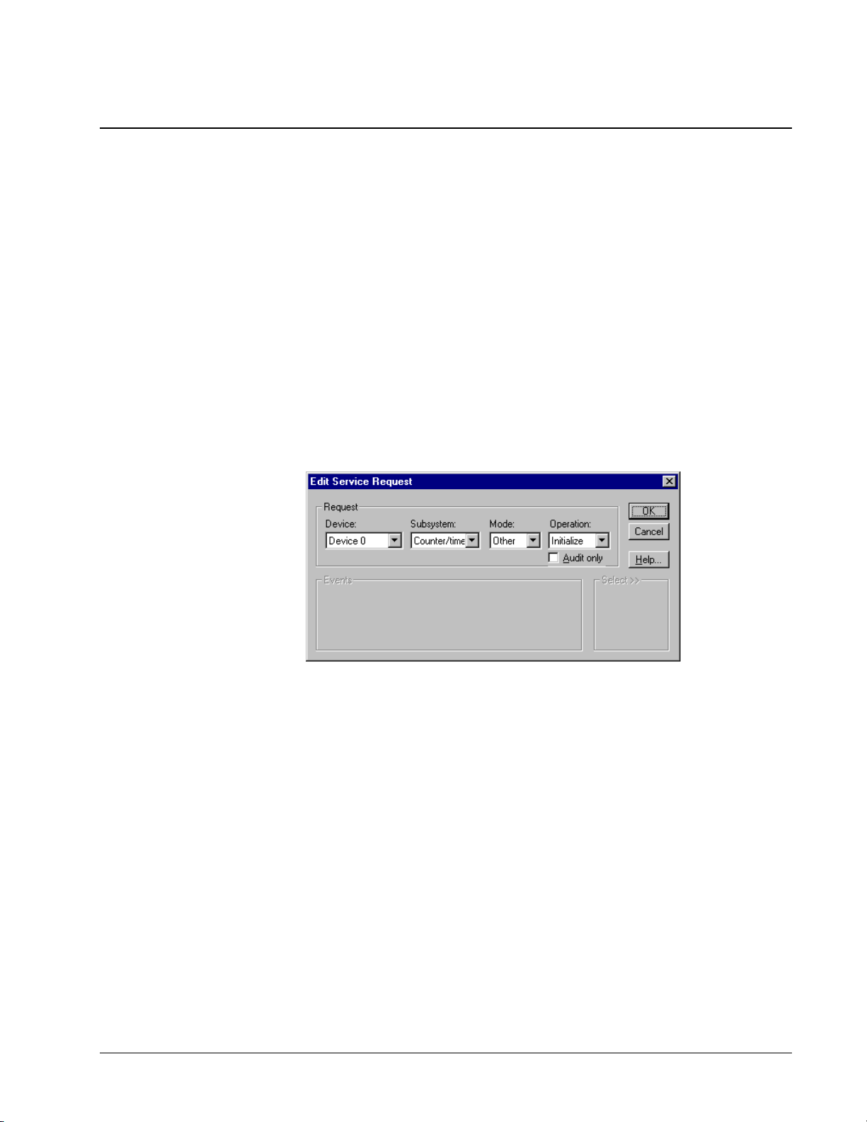
Using DriverLINX’s Service Requests
All counter/timer operations use the Service Request to pass your task specification
to DriverLINX. If you are using C/C++, the Service Request is a data structure
defined in the include file, “drvlinx.h”. If you are using the ActiveX (OCX) control
to program DriverLINX, the Service Request is an instance of the control object with
member properties that you set up.
The Edit Service Request
property page is a visual
representation of the Service
Request object that your
application programs.
Whatever language you are using, the principles of setting up a Service Request are
the same, although the syntax varies slightly with each language. This manual will
use the Service Request terminology displayed in the Edit Service Request property
page. See the example programs or the on-line DriverLINX Technical Reference
Manual for the language-specific syntax. See “Displaying the Edit Service Request
Dialog” on page 47 for how to pop-up the Edit Service Request dialog in your
applications.
Properties Common to All Service Requests
All Service Requests require that the application define the f ollowing properties in
the Request Group:
• Device—specifies the Logical Device number of a configured device as
the target of this Service Request.
• Subsystem—specifies the primary Logical Subsystem that is the target
of this Service Request.
• Mode—suggests the hardware tec hni que (Other, Polled, Int errupt,
DMA) that DriverLINX should use for this Service Request.
DriverLINX may select another mode to execute the task.
• Operation—specifies the primary command to execute for this Service
Request.
The additional Service Request groups and properties depend on the selected
subsystem, operation, and task your application intends to perform. See
“DriverLINX Counter/Timer Operations” on page 35.
DriverLINX Counter/Timer User’s Guide Programming Counter/Timers with DriverLINX • 39
Page 40

Modes and Operations for Counter/Timers
DriverLINX’s counter/timers use only the following modes:
• Other—used to initialize the counter/timer subsystem or configure a
Logical Channel without starting counting.
• Polled—specifies that applications issue software commands to
DriverLINX to start, monitor, and stop counters.
• Interrupt—specifies that DriverLINX performs counting operations at
each external interrupt.
For each Mode using the counter/ti mer subsystem, DriverLINX supports the
following operations:
Mode Operation Description
Other Initialize Initialize counter/timer subsystem
Configure Initialize a Logical Channel without starting counting
Polled Start Set up and start a counter/timer task
Status Return status and current value of a counter/timer
Stop Stop a counter/timer task
Interrupt Start Set up and start a background counter/timer task
Status Return status and position of next buffer sample to process
Stop Stop a background counter/timer task
For subsystems other than the
counter/timer, DriverLINX
executes Polled Mode tasks
synchronously.
Table 13 Allowed DriverLINX Counter/Timer Operations by Mode
Other Mode
DriverLINX executes Other Mode tasks synchronously, i.e., the task starts, executes,
and finishes before DriverLINX returns control back to the calling application.
Polled Mode
For the counter/timer subsystem, DriverLINX uses a quasi-synchronous technique.
For Start operations, DriverLINX initializes and starts the task befor e r e turning
control to the application. Applications then call DriverLINX to monitor the status of
the task or to stop the task. DriverLINX does not automatical ly stop polled tasks
unless DriverLINX detects an error while executing an application-issued command.
Interrupt Mode
DriverLINX executes Interrupt Mode tasks asynchronously, i.e., DriverLINX
initializes the task and then returns control to the application. At each interrupt,
DriverLINX briefly regains control from the application and either starts the task,
collects task data, reports status to the application, or stops the task.
The application specifies the work DriverLINX performs at each interrupt by the
properties in the Service Request. DriverLINX repor ts task s tatus to the application
40 • Programming Counter/Timers with DriverLINX DriverLINX Counter/Timer User’s Guide
Page 41

using either the Windows messaging system or control events. See “DriverLINX
f
dependent features, DriverLINX publishes
Events” on page 27.
Using Events to Control Service Requests
A few Service Request
operations do not use events.
DriverLINX uses the concept of an “event” to logically control the processing of a
Service Request task. For all tasks, DriverLINX re quires your application to specify
an event for the three events in the Events Group.
• Timing—specifies the timing, or pacing, clock DriverLINX uses
during processing a Service Request task.
• Start—specifies when DriverLINX starts counting or acquiring data
for this Service Request task.
• Stop—specifies when DriverLINX stops counting or acquiring data for
this Service Request task.
The example Service Request above defines a synchronous (polled) start of a
counter/timer channel. The application specifies the Logical Channel and
configuration for the counter/timer channel in the Rate Event pr operties (not shown
in the above dialog).
The on-line DriverLINX Technical Reference Manual defines an extensive set of
possible events for a wide variety of hardware and data-acquisition protocols. A
DriverLINX driver for counter/timers, however, uses only a few events that this
guide describes.
See the on-line DriverLINX
Technical Reference Manual
or more information about
the Logical Device
Descriptor.
DriverLINX defines events as hardware and vendor independent and allows
applications to use each event as a timing, start, or stop event whenever logical.
Some hardware boards, however, do no t support events that are common to the
majority of similar products, or they support only a subset of the event’s parameters.
To allow applications to handle hardwareboard-specific information in the Logical Device Descriptor. Applications that need
hardware independence should query the Logical Device Descriptor to determine the
available features of a board.
Events for the Counter/Timer
DriverLINX’s counter/timer operations use only the following events:
• None—indicates that the task does not re quire this event.
• Command—indicates that the Service Request starts or stops on
software c ommand.
DriverLINX Counter/Timer User’s Guide Programming Counter/Timers with DriverLINX • 41
Page 42
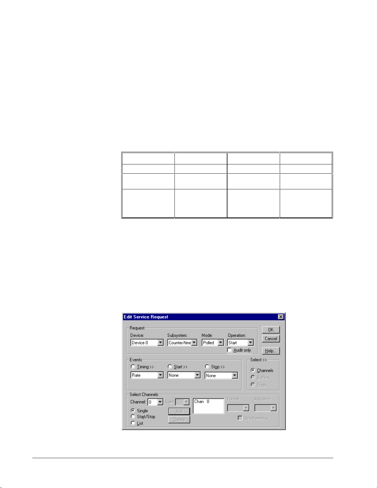
• Terminal Count—indicates that the Service Request completes when
the hardware has transferred all samples into or out of t he data buffers.
• Digital—when used as a start or stop event, specifies a digital input
channel to read and a masked set of bits to compare to a pattern. See
“Using Digital Start and Stop Events” on page 63. When used as a
timing event, specifies the external interrupt input line on the hardware,
which DriverLINX uses as a “clock” to pace the Service Request task.
See “Using the External Interrupt Input Line” on page 62.
• Rate—specifies the operating parameters for a Logical Channel of the
counter/timer subsystem.
The following table defines the events DriverLINX supports for each Mode on the
counter/timer subsystem.
Mode Timing Start Stop
Other Rate None None
Polled None
Rate
Interrupt Rate
Digital
Table 14 Allowed DriverLINX Counter/Timer Events by Mode
None
Command
None
Command
Digital
None
Command
None
Command
Digital
Terminal Count
Specifying Counter/Timer Channel s i n a Servic e
Request
For most counter/timer Service Request operations, you specify the Logical Channel
for the operation in the Channel property of a Rate Event. For group operations on
multiple Logical Channels, you specify the members of the group using the Select
Channels properties of a Service Request. Depending on the task and operation, your
application can specify a single Logical Channel, a consecutive range of Logical
Channels (Start/Stop), or a random list of Logical Channels.
42 • Programming Counter/Timers with DriverLINX DriverLINX Counter/Timer User’s Guide
Page 43

In a preemptive multitasking
stop members of the group. Note, however, that your application can specify Logical
system, the delay between
each instruction can vary
significantly and
unpredictably.
For channels in a group, DriverLINX uses a single hardware o peration to start or
Channels in a group that map to two different hardware chips on the CTM-10. In thi s
case, DriverLINX must use two separate instructions to control each chip.
Specifying Data Buffers in a Service Request
DriverLINX can transfer multiple samples in one Service Request b y using da ta
buffers.
• For group counter/timer requests that do not use interrupts, applications
can specify one buffer with a length equal to the number of Logical
Channels in the group. See “Polled Mode Groups” on page 65.
• For group counter/timer requests using external interrupts, applications
can specify multiple Logical Channels and up to 255 fixed-length
buffers of arbitrary size. See “Interrupt Mode Groups” on page 67.
• For untimed digital I/O transfers DriverLINX will use fast CPU block
I/O instructions. Applications can specify one Logical Channel and one
buffer as long as 128 KB. See “Rapidly Transferring a Block of Digital
Data” on page 75.
To transfer only a single value in a Service Request, see “Reading or Writing a
Single Digital Value” on page 68.
Interfacing to DriverLINX
To use DriverLINX, applications must incorporate the DriverLINX API into their
code. Applications can then control multiple DriverLINX drivers and multiple
Logical Devices using D riverLINX’s API.
The DriverLINX API supports multiple languages for Win32 application
development. Currently DriverLINX supports two different language interfaces. The
header files to support these languages are all in the DLAPI subdirectory where you
installed DriverLINX.
DriverLINX Counter/Timer User’s Guide Programming Counter/Timers with DriverLINX • 43
Page 44

• C/C++—a data structure and function call API available for 32-bit
C/C++ applications.
• ActiveX—or OLE 2.0 Custom Control (OCX) in a 32-bit interface.
Visual Basic 4.0, Microsoft Visual C++ 4.0, Delphi 2.0, and most new
language tools support 32-bit ActiveX controls.
A hardware-specific
DriverLINX driver may not be
available on all platforms.
All DriverLINX language interfaces bind to “DrvLNX32.DLL”. This DLL is
operating system independent and allows you to run your binary application on
either Windows 95/98/Me, or Windows NT/2000 as long as you have installed the
correct DriverLINX driver for your hardware and operating system.
Interface with C/C++
To use the C/C++ interface,
1. Add the following C header files in the DLAPI subdirectory to your
program after including the standard Wi ndows definit i ons:
#include “drvlinx.h” /* DriverLINX API */
#include “dlcodes.h” /* DriverLINX error codes and macros */
#include “oemcodes.h” /* OEM-specific model codes */
2. Add the follo wing impo rt library to your project or linker’s list of
libraries,
• DRVLNX32.LIB
Using Non-Microsoft C/ C++ Compilers
Note that some compiler tools, such as Borland C/C++, use a lib r a r y file format that
is not compatible with Microsoft’s format. Please check the DLAPI subdirectory
where you installed DriverLINX for library files co mpatibl e with your compiler. If
present, you will have to rename them to the above library names. If not present,
most compilers provide a tool to create a linking library given a DLL. Please consult
your compiler vendor’s documentation for assistance.
Interface with the Custom Control
DriverLINX supports one type of custom control:
1. OCX—32-bit ActiveX (formerly OLE) custom control
ActiveX Control
To add the ActiveX Custom Control (OCX) to your project, see the instructions for
your compiler and check the subdirectories where you installed DriverLINX for any
additional documentation. The filename of the 32-bit co ntrol is DLXOCX32.OCX.
The controls it contains are in a library called DriverLINX ActiveX
Controls.
Opening and Closing a DriverLINX Device Driver
To communicate with a physical device, applications must first open a device driver.
With DriverLINX, applications can either specify the name of a specific driver or
they can supply a blank name. In this case, or if the app specifies an unknown name,
DriverLINX will display the Open DriverLINX dialog requesting the user to select a
driver to open.
44 • Programming Counter/Timers with DriverLINX DriverLINX Counter/Timer User’s Guide
Page 45

For the MetraByte CTM Series, the name of the driver is “KMBCTM” and the driver
description is “MetraByte CTM Series”.
Applications should close the device driver when they no longer need its services.
Closing a DriverLINX driver stops all active tasks and unloads the driver from
memory.
Open a Driver in C/C++
To load and prepare a DriverLINX driver for application use, call the fo llowing
function:
HINSTANCE DLLAPI OpenDriverLINX (const HWND hWnd, LPCSTR name);
Parameter Type/Description
hWnd HWND Specifies one of the caller’s Window handles.
Name LPCSTR Specifies the name of the DriverLINX driver to load. If
NULL or the string specifies an unkn own driver, DriverLINX
displays the Open DriverLINX dialog box.
This function returns an “instance handle” that the application must use to identify
the DriverLINX driver for the SelectDriverLINX and CloseDriverLINX function
calls. See “Selecting a DriverLINX Device Driver” on page 46 and “Close a Driver
in C/C++” on page 45.
Open a Driver with the Custom Control
To load and prepare a DriverLINX driver for application use with either the VBX or
OCX control, simply set the Req_DLL_name property to the name of the desired
driver.
Close a Driver in C/C++
To stop all active tasks and unload a DriverLINX driver, call the following functio n:
VOID DLLAPI CloseDriverLINX (const HINSTANCE hDLL);
Parameter Type/Description
hDLL HINSTANCE Specifies the instance handle returned by an
OpenDriverLINX call.
DriverLINX Counter/Timer User’s Guide Programming Counter/Timers with DriverLINX • 45
Page 46

Close a Driver with the Custom Control
To stop all active tasks and unload a DriverLINX driver, sim ply set the
Req_DLL_name property to a null string.
Selecting a DriverLINX Device Driver
To specify which hardware to contro l , DriverLINX uses an addressing scheme that
consists of the following parts:
• Logical Driver—the DriverLINX software for one or more devices in a
manufacturer’s product family.
• Logical Device—the number you assigned to a particular physical
device during configuration.
• Logical Subsystem—the board’s hardware components the application
intends to use.
• Logical Channel(s)—the data channels of a subsystem that the
application intends to use.
Applications specify the Logical Device, Subsystem, and Channel in the Service
Request. DriverLINX uses the last driver the application opened or selected for the
Logical Driver address.
If your application is controlling multiple devices that use different DriverLINX
device drivers, then the application must select the correct DriverLINX Logical
Driver before sending it a Service Request or other command.
Selecting a Driver in C/C++
To select a DriverLINX Logical Driver, call the following function before callin g
any other D riverLINX function:
HINSTANCE DLLAPI SelectDriverLINX (const HINSTANCE hDLL);
Parameter Type/Description
hDLL HINSTANCE Specifies the instance handle returned by an
OpenDriverLINX call.
This function returns the “instance handle” of the last selected driver, if
SelectDriverLINX succeeds. If DriverLINX detects an error, SelectDriverLINX
returns zero.
Selecting a Driver with the Custom Control
The application should create at least one separate instance of the control for each
DriverLINX driver the application opens. See “Open a Driver with the Custom
Control” on page 45 for how to open a DriverLINX driver. The control instance will
automatically select the correct DriverLINX driver before sending any commands to
DriverLINX.
46 • Programming Counter/Timers with DriverLINX DriverLINX Counter/Timer User’s Guide
Page 47

Displaying the Edit Service Request Dialog
Applications can easily display the Edit Service Request property page at run time.
Most often yo u will find this a handy tool while you a re developing and testing your
application, but you can also use it as a “hidden” feature for supporting problems
with a shipping product. Use this feature to
• experiment with different hardware capabilities,
• visually inspect how your application set up a Service Request,
• modify an incorrect property during testing without recompiling your
program,
• quickly learn how your application responds to different data-
acquisition rates or conditions,
• act as a temporary user interface before developing your own interface.
To pop-up the Edit Service Request dialog, fir st initialize the Service Request for any
task of your choosing. Then set the EDIT flag. When your application calls
DriverLINX, it will display the dialog. When the user dismisses the pro perty page,
DriverLINX will remove the EDIT flag and return a result code. If DriverLINX
returns no error, simply recall DriverLINX with the current Service Request to have
DriverLINX execute it. If DriverLINX returns an error, the user canceled the Ed it
Service Request property page. Your application should probably not execute the
Service Request.
Display Edit Service Request Dialog Using C/C++
//************************************************
// Use this procedure to show Edit Service Request
//************************************************
UINT ShowEditSR (LPServiceRequest pSR)
{
// Caller sets up Service Request
pSR->operation = (Ops)(pSR->operation | EDIT);
// DriverLINX automatically removes EDIT flag
// Caller can execute SR if there are no errors
return DriverLINX(pSR);
}
Display Edit Service Request Dialog Using Visual Basic
’ Use this procedure to show Edit Service Request
Function ShowEditSR (dl As DriverLINXSR) As Integer
’ Caller should set up Service Request
dl.Req_op_edit = DL_True
dl.Refresh
’ DriverLINX automatically removes Req_op_edit flag
’ Caller can execute SR if there are no errors
ShowEditSR = dl.Res_result
End Function
DriverLINX Counter/Timer User’s Guide Programming Counter/Timers with DriverLINX • 47
Page 48

Reporting a DriverLINX Error
Applications can use DriverLINX to display a pop-up message box to the user
describing the error or result of the last DriverLINX Service Request. Simply replace
the value of the Operation property in the Service Request with the “MessageBox”
operation and resubmit the Service Request to DriverLINX.
The DriverLINX message box displa ys the error severity, subsystem, and error text.
Error severities are
• Warning—errors that do not result in fail ure o f fu nctio n, such as data
overruns.
• Abort—Request ed function was not performed. No ongoing functions
were disturbed. Request may be repeated after correcting the error.
• Fatal—Request was terminated wit h an unrecoverable error and/or
data loss.
• Internal—Unexpected errors resulting from corruption of device driver
data or device driver programmi ng errors.
See the on-line DriverLINX Technical Reference Manual for a list of errors.
Display DriverLINX Message Box Using C/C++
//**************************************************
// Use this procedure to display DriverLINX messages
//**************************************************
UINT ShowDriverLINXMessage (LPServiceRequest pSR)
{
// Assume caller passed an initialized Service Request
UINT lastOp;
lastOp = pSR->operation; // save current operation
pSR->operation = MESSAGEBOX;
UINT result;
result = DriverLINX(pSR);
pSR->operation = (Ops)lastOp; // restore last operation code
return result;
}
48 • Programming Counter/Timers with DriverLINX DriverLINX Counter/Timer User’s Guide
Page 49

Display DriverLINX Message Box Using Visual Basic
property of a currently running Service Request
’ Use this procedure to display DriverLINX messages
Function ShowDriverLINXMessage(dl As DriverLINXSR) As Integer
Dim lastOp As Integer
With dl
lastOp = .Req_op
.Req_op = DL_MESSAGEBOX
.Refresh
.Req_op = lastOp
ShowDriverLINXMessage = .Res_result
End With
End Function
Stopping A DriverLINX Task
Applications can use a Service Request to stop a running DriverLINX task.
Applications may need to stop a task that is running too long, that a user wants to
abort, or that requires a software command to complete. For the counter/timer
subsystem, DriverLINX requires that all applications use a stop Service Request to
end polled tasks because DriverLINX cannot always detect task comp letion
automatically. DriverLINX can automatically terminate background tasks if the
Service Request contains a Stop Event that will eventually become true.
A Stop Service Request must
have a valid taskId property
that identifies a previous task.
DriverLINX sets taskId in the
Service Request after
successfully starting a task.
To stop a task, change the Operation
to “STOP” and submit the Service Request to DriverLINX. If Driver LINX s to ps the
task, it returns no error in the Result property. If the Service Request is not running
when the application attempts to stop it, DriverLINX returns a “Service Request not
found” error.
Stopping a Task Using C/C++
//***********************************************
// Use this procedure to stop any Service Request
//***********************************************
UINT StopDriverLINXTask (LPServiceRequest pSR)
{
// Use same Service Request from START command
// Change operation code
pSR->operation = STOP;
// Call DriverLINX to perform Service Request
return DriverLINX(pSR);
}
Stopping a Task Using Visual Basic
’***********************************************
’ Use this procedure to stop any Service Request
’***********************************************
Function StopDriverLINXTask (dl As DriverLINXSR) As Integer
’ Use same Service Request from DL_START command
’ Change operation code
With dl
.Req_op = DL_STOP
.Refresh
StopDriverLINXTask = .Res_result
End With
End Function
DriverLINX Counter/Timer User’s Guide Programming Counter/Timers with DriverLINX • 49
Page 50

Initializing the Device
Device initialization is the first step that all applications should perform after loading
a DriverLINX driver. Device initialization cancels all active Service Requests o n the
device that the current process started and does a software reset of all subsystems.
Because DriverLINX supports sharing hardware devices among multiple processes,
the additional effects of device initialization vary.
• If the application is the only process using the device, DriverLINX
reconfigures and reinitializes the hardware to the user-defined state. If
you do not define initialization values for output ports, Driver LINX
writes zeros to output ports when the driver first loads and the last
known output value at any other Device Initialization.
• If multiple processes are sharing the device, DriverLINX does not
reconfigure or reinitialize the hardware state.
• If another process is executing a Service Request on the device,
DriverLINX performs initialization steps that will not interfere with the
other application and then returns a Device Busy error to app
requesting initialization.
To initialize a device, set up the Service Request Group as follows:
Device Subsystem Mode Operation
<Logical Device> DEVICE OTHER INITIALIZE
The other properties of a Service Request are unused and sho uld be set to zero.
50 • Programming Counter/Timers with DriverLINX DriverLINX Counter/Timer User’s Guide
Page 51

Initialize the Device Using C/C++
//**********************************************
// Use this procedure to initialize the hardware
//**********************************************
UINT InitDriverLINXDevice (LPServiceRequest pSR, UINT Device)
{
memset(pSR, 0, sizeof(DL_SERVICEREQUEST));
DL_SetServiceRequestSize(*pSR);
pSR->hWnd = GetSafeHwnd();
pSR->device = Device;
pSR->subsystem = DEVICE;
pSR->mode = OTHER;
pSR->operation = INITIALIZE;
return DriverLINX(pSR);
}
Initialize the Device Using Visual Basic
’ Use this procedure to initialize the hardware
Function InitDriverLINXDevice(dl As DriverLINXSR, ByVal Device As
Integer) As Integer
With dl
.Req_device = Device
.Req_subsystem = DL_DEVICE
.Req_mode = DL_OTHER
.Req_op = DL_INITIALIZE
’ No events, buffers, channels needed
.Evt_Tim_type = DL_NULLEVENT
.Evt_Str_type = DL_NULLEVENT
.Evt_Stp_type = DL_NULLEVENT
.Sel_buf_N = 0
.Sel_chan_N = 0
.Refresh
InitDriverLINXDevice = .Res_result
End With
End Function
Initializing a Counter/Timer Subsystem
Applications may perform a subsystem initialization at any time to abort all
outstanding Service Requests that the calling process o riginally initiated. Usually
applications do not need to call this service.
DriverLINX Counter/Timer User’s Guide Programming Counter/Timers with DriverLINX • 51
Page 52

To initialize a subsystem, set up the Service Request Group as follows:
Device Subsystem Mode Operation
<Logical Device> CT OTHER INITIALIZE
The other properties of a Service Request are unused and sho uld be set to zero.
Initialize a Subsystem Using C/C++
//*************************************************************
// Use this procedure to initialize the counter/timer subsystem
//*************************************************************
UINT InitCounterTimers (LPServiceRequest pSR, UINT Device)
{
memset(pSR, 0, sizeof(DL_SERVICEREQUEST));
DL_SetServiceRequestSize(*pSR);
pSR->hWnd = GetSafeHwnd();
pSR->device = Device;
pSR->subsystem = CT;
pSR->mode = OTHER;
pSR->operation = INITIALIZE;
return DriverLINX(pSR);
}
Initialize a Subsystem Using Visual Basic
’ Use this procedure to initialize the counter/timer subsystem
Function InitCounterTimers(dl As DriverLINXSR, ByVal Device As Integer)
As Integer
With dl
.Req_device = Device
.Req_subsystem = DL_CT
.Req_mode = DL_OTHER
.Req_op = DL_INITIALIZE
’ No events, buffers, channels needed
.Evt_Tim_type = DL_NULLEVENT
.Evt_Str_type = DL_NULLEVENT
.Evt_Stp_type = DL_NULLEVENT
.Sel_buf_N = 0
.Sel_chan_N = 0
.Refresh
InitCounterTimers = .Res_result
End With
End Function
Using Messages and Events
DriverLINX can report task information to your application usi ng the Windows
messages or events. See “DriverLINX Events” on page 27 and the on-line
DriverLINX Technical Reference Manual for more information.
52 • Programming Counter/Timers with DriverLINX DriverLINX Counter/Timer User’s Guide
Page 53

Events for Foreground Tasks
For polled mode tasks, DriverLINX only reports ServiceStart and ServiceDone
events to your application. This provides consistency with the background tasks
modes so that if your application uses these events, its logic is the same for
foreground and background modes.
If you are trying to use foreground tasks in a fast loop and you are not using these
messages, you may wish to tell DriverLINX not to send these messages. This can
sometimes increase the speed of the loop.
Disable ServiceStart and ServiceDone Using C/C++
//**********************************************************
// Use this procedure to disable SeviceStart and ServiceDone
//**********************************************************
void DisableServiceStartDone (LPServiceRequest pSR)
{
// Caller sets up Service Request
pSR->taskFlags |= NO_SERVICESTART | NO_SERVICEDONE;
}
Disable ServiceStart and ServiceDone Using Visual Basic
’**********************************************************
’ Use this procedure to disable SeviceStart and ServiceDone
’**********************************************************
Sub DisableServiceStartDone (dl As DriverLINXSR)
’ Caller sets up Service Request
With dl
.Sel_taskFlags = .Sel_taskFlags Or NO_SERVICESTART Or
NO_SERVICEDONE
End With
End Sub
Events for Background Tasks
By default, DriverLINX sends background tasks ServiceStart and ServiceDone
messages and always sends DataLost and CriticalError messages if DriverLINX
detects any problems. DriverLINX only sends the other messages if the application
tells DriverLINX to do so.
Enable and Use Messages Using C/C++
Enable Optional Messages
//**********************************************************
// Use this procedure to enable optional DriverLINX messages
//**********************************************************
void EnableAllEvents (LPServiceRequest pSR)
{
// Caller sets up Service Request
if (pSR->lpBuffers)
pSR->lpBuffers->notify |= NOTIFY | NOTIFY_START | NOTIFY_STOP;
}
DriverLINX Counter/Timer User’s Guide Programming Counter/Timers with DriverLINX • 53
Page 54

Message Handling in C/C++ or MFC
//**********************************************
// C/C++ procedure for using DriverLINX messages
//**********************************************
// Register custom DriverLINX message
UINT gDL_Msg = RegisterWindowMessage(DL_MESSAGE);
// If you’re using MFC, then add the following to your classes
// message map:
// BEGIN_MESSAGE_MAP(xxx, yyy)
// ON_REGISTERED_MESSAGE(gDL_Msg, OnDLMessage)
// END_MESSAGE_MAP()
//
// Then change the function below to
// LRESULT OnDLMessage (WPARAM wParam, LPARAM lParam)
// and delete the line:
// if (message == gDL_Msg)
LRESULT OnDLMessage (HWND hWnd, UINT message,
WPARAM wParam, LPARAM lParam)
{
// Was message posted by DriverLINX?
if (message == gDL_Msg)
switch (wParam) {
case DL_SERVICESTART:
break;
case DL_SERVICEDONE:
switch (getSubSystem(lParam)) {
case CT:
break;
} // switch
break;
case DL_TIMERTIC:
break;
case DL_BUFFERFILLED:
break;
case DL_DATALOST:
break;
case DL_CRITICALERROR:
break;
} // switch
return 0;
}
Enable and Use Messages Using Visual Basic
Enable Optional Events
'********************************************************
' Use this procedure to enable optional DriverLINX events
'********************************************************
Sub EnableAllEvents (dl As DriverLINXSR)
' Caller sets up Service Request
With dl
If .Sel_buf_N > 0 Then
.Sel_buf_notify = .Sel_buf_notify Or DL_NOTIFY Or DL_NOTIFY_START
Or DL_NOTIFY_STOP
End If
End With
End Sub
Event Handling in Visual Basic
Visual Basic will automatically generate for all DriverLINX events empty
subroutines where you can add event-handling logic. See the on-line DriverLINX/VB
Technical Reference Manual for mo r e d e tails.
54 • Programming Counter/Timers with DriverLINX DriverLINX Counter/Timer User’s Guide
Page 55

Counter Output
Counter/timers generate an output signal when they reach their limit or rollover the
count value. When using the Am9513, the application can explicitly program how
the counter/timer channel signals the output terminal. The output mode for the 8254
is less flexible and dependent on the hardware’s counter mode. DriverLINX supports
the outputs shown in “Table 6 Allowed Values for Rate Event Output Property” on
page 25.
Applications can also select DriverLINX’s default output value for any counter/ti mer
channel. For every counter/timer mode, DriverLINX defines a default output value
as shown in the following table:
Generator Description
Default Output
Intel 8254 KPCI-3140 Am9513
RateGen Periodic rate generator LoActive LoToggled HiActive
SqWave Square wave generator HiToggled LoToggled Toggled
VDCGen Variable duty cycle rate
generator
BurstGen Burst rate generator HiActive
Divider Frequency divider LoToggled HiActive
Freq Frequency counter HiActive
Interval Interval timer HiActive
Count Event counter HiActive
PulseWd Pulse width measurement HiActive
SplitClk Split frequency rate
generator
FskGen Frequency-shift keying Toggled
PulseGen Pulse generator LoToggled Toggled
Retrig
RateGen
Retrig
SqWave
Count32 32-bit event counter HiActive
Count64 64-bit event counter HiActive
Freq32 32-bit frequency counter HiActive
FreqRatio Frequency ratio counter HiActive
OneShot One-shot pulse or strobe LoToggled
Retrig
OneShot
Retriggerable rate generator HiActive
Retriggerable square wave
generator
Retriggerable one-shot pulse
or strobe
LoToggled HiToggled
HiActive
Toggled
LoActive HiActive
(Mode 0),
LoActive
(Mode 5)
LoToggled
(Mode 1),
LoActive
(Mode 4)
HiActive
Table 15 Default Counter/Timer Output Values
DriverLINX Counter/Timer User’s Guide Programming Counter/Timers with DriverLINX • 55
Page 56

Status Polling a Counter/Timer
Applications can monitor the current value and status of one or more counter/timer
channels using a Service Request. DriverLINX’s handling of status polling for
counter/timer subsystem depends on the type of task.
• In non-buffered, polled mode, DriverLINX returns the current counter
value and status in the Results Group of the Service Request.
• When using a buffered, polled group task, DriverLINX saves the
current counter value in the buffer for each Logical Channel in the
group.
• For buffered, interrupt tasks, DriverLINX returns the current buffer
number and the position of the next sample to write.
See “Converting Between Counts and Time” on page 58 for how to convert counts to
time.
Polling a Counter/Timer Using C/C++
//*******************************************
// Use this procedure to read a counter/timer
//*******************************************
DWORD ReadCounterTimer (LPServiceRequest pSR, UINT* pResult)
{
UINT result;
// Use same Service Request from a Start Service Request
// Change operation code
pSR->operation = STATUS;
// Call DriverLINX to perform Service Request
result = DriverLINX(pSR);
if (pResult)
*pResult = result;
if (result != NoErr)
return (DWORD)-1;
if (pSR->status.u.timerStatus.status == done)
StopDriverLINXTask(pSR);
// Return current count
return pSR->status.u.timerStatus.count;
}
56 • Programming Counter/Timers with DriverLINX DriverLINX Counter/Timer User’s Guide
Page 57

Polling a Counter/Timer Using Visual Basic
’*******************************************
’ Use this procedure to read a counter/timer
’*******************************************
Function ReadCounterTimer (dl As DriverLINXSR, result As Integer) As
Long
’ Use same Service Request from a Start Service Request
With dl
’ Change operation code
.Req_op = DL_STATUS
.Refresh
result = .Res_result
If .Res_result <> DL_NoErr Then
ReadCounterTimer = -1
Exit Function
End If
End With
If dl.Res_Tim_status = DL_done Then
StopDriverLINXTask dl
End If
’ Return current count
ReadCounterTimer = dl.Res_Tim_count
End Function
Configuring a Counter/Timer Channel
Applications can configure and arm a Logical Channel for a counter/timer without
actually starting a task on the counter/timer. This is useful for creating custom
counter/timer operations that use multiple counters and for pre-configurin g several
counter/timer channels that you want to start simultaneously as a group. See
“Individual and Group Tasks” on page 29.
When an application configures a counter/timer, DriverLINX initializes the hardware
for the requested Logical Channel, but it does not start, or arm, the counter. To start a
previously configured counter, the application should add the Logical Channel to the
channel list of a group task. See “Controlling Group Tasks” o n page 63.
To configure a counter/timer, set up the Service Request Group as follows:
Device Subsystem Mode Operation
<Logical Device> CT OTHER CONFIGURE
Set up the Events Group as follows:
Timing Start Stop
Rate None None
The properties of the timing event control how DriverLINX configures the hardware.
A CONFIGURE operation sets the mode of only one counter so, in general, the taskoriented functions cannot be used for the mode. See “Hardware Reference” on page
113 Operating Modes for details on the available modes and the corresponding
hardware behavior.
DriverLINX Counter/Timer User’s Guide Programming Counter/Timers with DriverLINX • 57
Page 58

Converting Between Counts and Time
DriverLINX expresses all time units as the number of t ics o f a board’s master clock.
The Period and onCount properties of the Service Request as well as the counter
values DriverLINX returns are all in tic units. To make it easy for applications to
convert between tic units and seconds, DriverLINX supports two methods:
• Sec2Tics—converts time in seconds to hardware tic units.
• Tics2Sec—converts time in hardware tic units to seconds.
Time Conversion in C/C++
Sec2Tics
This function converts the time in seconds for a counter/timer Logical Channel to
clock tics. The function syntax is
DWORD DLLAPI Sec2Tics (UINT device, SubSystems subsystem, UINT
LogicalChannel, float secs);
This function returns the result in clock tic units as an unsigned 32-bit word. If the
function detects an error, it returns zero.
Parameter Type/Description
device WORD Specifies the Logical Device of the
counter/timer board.
subsystem SubSystems Specifies the counter/timer
subsystem.
LogicalChannel UINT Specifies the Logical Ch annel of the
counter/timer. Symbolic values, e.g.,
DEFAULTTIMER, are acceptable.
Secs float Specifies the time value in seconds to
convert to tics.
Tics2Sec
This function converts the time in clock tics for a counter/timer Logical Channel to
seconds. T he function s ynt ax is
BOOL DLLAPI Tics2Sec (UINT device, SubSystems subsystem, UINT
LogicalChannel, DWORD tics, float* pFloat);
This function returns TRUE if the conversion was successful, otherwise it returns
FALSE. The function returns the converted result at pFloat.
Parameter Type/Description
device UINT Specifies the Logical Device of the
counter/timer board.
subsystem SubSystems Specifies the counter/timer
subsystem.
LogicalChannel UINT Specifies the Logical Ch annel of the
counter/timer. Symbolic values, e.g.,
58 • Programming Counter/Timers with DriverLINX DriverLINX Counter/Timer User’s Guide
Page 59

DEFAULTTIMER, are acceptable.
tics DWORD Specifies the counter/timer value
in hardware tics.
pFloat float* Specifies a 32 - bit pointer to a singe-
precision floating-point variable where
DriverLINX stores the converted result in
seconds. If an erro r occurs, the value of this
field is undefined.
Time Conversion Using the Custom Control
For the 16-bit VBX, the following functions are DLL exports from
“DrvLnxVB.DLL”. For the ActiveX controls, the functions are control methods.
DLSecs2Tics
This method converts the time in seconds for a counter/timer Logical Channel to
clock tics. The method syntax is
<control>.DLSecs2Tics (ByVal LogicalChannel As Integer, ByVal secs As
Single) As Long
This method returns the result in clock tic units as a 32-bit integer. If the method
detects an error, it returns zero.
Parameter Type/Description
LogicalChannel Integer Speci fies t he Logical Channel of the
counter/timer. Symbolic values, e.g.,
DL_DEFAULTTIMER, are acceptabl e.
Secs Single Specifies the time value to convert i n
seconds.
DLTics2Secs
This method converts the time in clock tics for a counter/timer Logical Channel to
seconds. The method syntax is
<control>.DLTics2Secs (ByVal LogicalChannel As Integer, ByVal tics As
Long) As Single
This method returns the converted time in seconds. If an error o ccurs, DriverLINX
returns 0.0.
Parameter Type/Description
LogicalChannel Integer Speci fies t he Logical Channel of the
counter/timer. Symbolic values, e.g.,
DL_DEFAULTTIMER, are acceptabl e.
tics Long Specifies the counter/timer value in
hardware tics.
DriverLINX Counter/Timer User’s Guide Programming Counter/Timers with DriverLINX • 59
Page 60

Using Background Tasks
DriverLINX can run counter/timer tasks in the background asynchronously
collecting data while the application processes other data in the foreground.
DriverLINX can support asynchronous mode only if the counter/timer board
supports interrupts, and you have configured the board to use an available interrupt.
Background, interrupt-driven tasks can either report an event to the application at
each interrupt or they can use a data buffer to collect samples at each interrupt.
Using a Counter/Timer to Generate Clock
Messages
DriverLINX can post a “timer tic” message or event to an application at each
interrupt by a counter/timer channel if the Service Request does not specify any data
buffers. See “DriverLINX Events” on page 27.
To start a counter/timer generating an interrupt, set up the Request Group in a
Service Request as follows:
Device Subsystem Mode Operation
<Logical Device> CT INTERRUPT START
Set up the Events Group as follows:
Timing Start Stop
Rate None None
Then set up the timing event using any of the single counter/ti mer Rate Events
described in this manual or in “Hardware Reference” on page 113 Operating Modes.
To create a simple, periodic clock on any available Logical Channel, use the
following setup for a Rate Event:
Mode Period Gate Pulses
RATEGEN period DISABLED 0
Note that Windows or your application cannot keep up with the highest interrupt rate
the counter/timer can generate. At moderately high rates, your application message
queue may overflow and timer tics will be lost. At very high interrupt rates,
Windows will skip interrupts and may become very sluggish or unstable.
To create a single timer tic message after a known interval, use the following setup
for a Rate Event:
Mode Period Gate Pulses
ONESHOT period DISABLED 1
60 • Programming Counter/Timers with DriverLINX DriverLINX Counter/Timer User’s Guide
Page 61

Note that the counter/timer hardware design only allows DriverLINX to support
timer tics on one running counter/timer at a time.
Storing the Counter/Timer Value at Each Interr upt
DriverLINX can store the current value of a counter/timer into a memory buffer at
each interrupt.
Note that Windows or your application cannot keep up with the highest interrupt rate
the counter/timer can generate. At high interrupt rates, Windows will skip interrupts
and may become very sluggish or unstable.
To start a counter/timer generating an interrupt, set up the Request Group in a
Service Request as follows:
Device Subsystem Mode Operation
<Logical Device> CT INTERRUPT START
Set up the Events Group as follows:
Timing Start Stop
Rate or
Digital
Command or
Digital
Terminal Count or
Command or
Digital
The Timing Event specifies the pacing or interrupt source.
• Rate Events use a counter/timer channel to generate an interrupt source.
Use any of the single counter/timer modes described in “Hardware
Reference” on page 113 Operating Modes.
• Digital Events use the hardware’s external interrupt input line as the
interrupt source. See “Using the External Interrupt Input Line” on page
62.
To create a simple, periodic clock on any available Logical Channel, use the
following setup for a Rate Event:
Mode Period Gate Pulses
RATEGEN period DISABLED 0
DriverLINX Counter/Timer User’s Guide Programming Counter/Timers with DriverLINX • 61
Page 62

The Start and Stop Events determine when the DriverLINX task starts and stops
saving counter values at e ach interr upt.
• Command—starts or sto ps the task on software command.
• Digital—starts or stops the task when the masked dig ital input satisfies
the pattern matching condition in the event. See “Using Digital Start
and Stop Events” on page 63.
• Terminal Count—stops the task DriverLINX has filled the buffers
with count values once.
DriverLINX can optionally
post “buffer filled” messages
to the application as
DriverLINX completes
processing each buffer. See
“DriverLINX Events” on
page 27.
DriverLINX has no software
control over the CTM’s
external interrupt enable
input.
To start or stop data transfer on software command, use Command Events for the
Start or Stop Event. If you use a Stop Command or Digital Event, after DriverLINX
finishes processing the last buffer, it will automatically s tar t writi ng data again into
the first buffer. With a Stop Command, DriverLINX will acquire data until the
application resets the Service Request’s Operation property to Stop and resub mits
the Service Request to DriverLINX.
Select Buffers
Set the number of Buffers between 1 and 255 and the BufferSize property to the
number of bytes to transfer. Buffers must contain an integral multiple of the total
number of channels specified in the Service Request. DriverLINX can optionally
post “buffer filled” messages to the application as DriverLINX completes processing
each buffer. See “DriverLINX Events” on page 27.
Using the External Interrupt Input Line
Use a Digital Timing Event to tell DriverLINX which external hardware input
source to use for the interrupt. DriverLINX models the external hardware interrupt
lines as 1-bit digital input ports. Set up the Digital Event as follows:
Channel Mask Match Pattern
<external interrupt
channel>
<input lines to test> FALSE or “not
equal”
0
• For the Channel, either specify the Logical Channel DriverLINX has
assigned as the external interrupt input line (see the Logical Device
Descriptor) or use a har dware-independent, symbolic Logical Channel ,
DI_EXTCLK. DriverLINX automatically replaces this value with the
correct hardware channel when the app sends the Service Request to
DriverLINX.
• Use the Mask property to indicate which line(s) to enable for interrupts.
Most boards only support one external interrupt line so use a value of 1.
• Set the Match and Pattern properties to “not equal zero”. This specifies
that a rising edge at any input will trigger the interrupt. Other values for
these properties will generate an error.
62 • Programming Counter/Timers with DriverLINX DriverLINX Counter/Timer User’s Guide
Page 63

Using Digital Start and Stop Events
DriverLINX tests the requested Logical Channel for the trig ger event. If DriverLINX
found, stops processing data immediately. Note that a digital input may change value
DriverLINX can optionally
post “start trigger” and “stop
trigger” messages to the
application. See the on-line
DriverLINX Technical
Reference Manual for more
information about messages.
To start or stop data transfer when a certain condition occurs on a digital input
channel, use a Digital Event for the Start or Stop Event. At each interrupt,
detects the start trigger, it starts processing the data buffers immediately. After
processing one sample or scan, DriverLINX tests for the stop trigger event, and, if
between the time the interrupt occurs and when DriverLINX reads the Logical
Channel for a trigger.
Set up a Digital Event as follows:
Channel Mask Match Pattern
<Logical Channel> <input lines to test> 0 - “not equal” or
1 - “equal”
• For the Channel property, specify the Logical Channel for any digital
input port.
• Use the Mask property to select which input bits to test as a digital
trigger.
• Use the Match property to select how DriverLINX tests for a digital
trigger.
• Use the Pattern property to specify the bits DriverLINX uses for
comparison.
<pattern to match>
DriverLINX supports two typ es of digital triggers tests based on the value of the
Match property.
Match Value Trigger Test
0 — Not Equals Channel AND Mask != Pattern
1 — Equals Channel AND Mask == Pattern
With a Stop Digital Event, DriverLINX will terminate acquisition either when the
digital input value satisfies the digital trigger condition or when the application sends
a stop operation.
If the Delay property of a Digital Event is not zero, DriverLINX will not trigger the
event until it has counted the number of additional interrupts the app sp ecified in t he
Delay property. As a special case, if the stop Delay property has the maximum count,
DriverLINX treats this event as “stop on command”, but it will send a message to the
application each time it detects the stop event.
Controlling Group Tasks
Group tasks give your application more control over the counter/ti mer subsystem. It
can configure counter/timers in any basic mode that the hardware supports, and start
or stop multiple counter/timers at the same time. You can create polled mode groups
and interrupt mode groups. For polled mode groups, DriverLINX starts or stops all
counter/timers at the same time. Applications can poll the status of counter/timers in
DriverLINX Counter/Timer User’s Guide Programming Counter/Timers with DriverLINX • 63
Page 64

the group while the task is running. For interrupt mode groups, DriverLINX also
starts or stops all counter/timers at the same time, but DriverLINX writes the current
counter/timer values into a buffer at each interrupt. The trade-off is that your
application must perform its own analysis of the buffers as DriverLINX cannot
discern the aggregate function of your group task.
To use a group task, you must first ind ividually c onfigure t he counter/timers you
wish to use in a group. To configure a Logical Channel, you set up the Logical
Channel wit h the same properties you would normally use for a basic counter/ t imer
task, but you must change the Operation property from “Start” to “Configure”. See
“Configuring a Counter/Timer Channel” on page 57 and “Hardware Reference” on
page 113 Operating Modes.
To designate Logical Channels as members of a group, set up a Service Request and
use the Select Channels Group to specify the Logical Channels in the group.
Select Channels
To tell DriverLINX which Logical Channels are members of the group task, use the
Select Channels Group properties. You can specify a group consisting of a single
channel, a range of channels, or a list of channels.
To set up the Select Channels Group for one Logical Channel:
Number of channels Start Channel Format
1 <Logical Channel> native
Specify the number of
channels as 2, not the number
of channels in the consecutive
sequence.
To set up the Select Channels Group for a consecutive range of channels:
Number of
Start Channel Stop Channel Format
channels
2 <Logical Channel> <Logical Channel> native
DriverLINX scans all channels between the starting and stopping channel. If the
starting channel is greater than the stopping channel, the channel sequence wraps
around at the highest Logical Channel and continues from zero.
To set up the Select Channels Group for a random channel li st:
Number of
Channel
GainI Format
i
channels
<size of list> <Logical Channel> 0 native
DriverLINX can transfer one Logical Channel at each interrupt or transfer all the
specified Logical Channels (a scan) at each interrupt. The Simultaneous property
tells DriverLINX to transfer either one channel (unchecked or false) or all channels
(checked or true) at each interrupt. Most counter/timer hardware does not support
true simultaneous transfers, so DriverLINX rapidly reads each channel in a loop.
64 • Programming Counter/Timers with DriverLINX DriverLINX Counter/Timer User’s Guide
Page 65

Polled Mode Groups
In a preemptive multitasking
system, the delay between
two instructions can vary
significantly and
unpredictably.
For a polled mode group, DriverLINX ideally starts or stops all counter/timers in the
group using a single hardware operation. However, some hardware does not support
this for all Logical Channel s. The CTM-10 uses one Am9513 chip s to control
Logical Channels 0 to 4 and another chip for Logical Channels 5 to 9. In this case,
DriverLINX must use two separate instructions to control each chip. For boards that
use an 8254 chip, DriverLINX must use a separate instruction for each Logical
Channel.
To start a polled mode group, set up the Request Group as follows:
Device Subsystem Mode Operation
<Logical Device> CT POLLED START
Set up the Events Group as follows:
Timing Start Stop
None None None
The Service Request needs no Timing Event as each counter/timer in a group runs
independently. See “Select Channels” on page 64 for how to specify the Logical
Channels for a group .
If you need to read the current counter values of channels in a group, set up a single
buffer with one sample for each Logical Channel in the Service Request. When your
application performs status polling with the Service Reques t (see “Status Polling a
Counter/Timer” on page 56), DriverLINX will store the current counter value of
every channel in the Service Request into the buffer rather than returning a si ngle
value in the Service Request. If your application does not need status polling, set the
number of buffers to zero in the Service Request.
Starting a Polled Mode Group Using C/C++
Note that the following C example will cause memory leaks unless the calling
application takes responsibility for freeing the following memory after stopping the
Service Request for the group task:
• Channel Gain List in the Service Request
• Buffer List in the Service Request
• Buffers in the Service Request’s Buffer List
DriverLINX Counter/Timer User’s Guide Programming Counter/Timers with DriverLINX • 65
Page 66

//*****************************************************
// Use this procedure to start a polled mode group task
//*****************************************************
UINT StartPolledGroup (LPServiceRequest pSR,
UINT LogicalDevice,
UINT nChannels,
int channels[])
{
// Set up Service Request to perform task
// First zero Service Request structure
memset(pSR, 0, sizeof(DL_SERVICEREQUEST));
// Then initialize structure size
DL_SetServiceRequestSize(*pSR);
// Set up Request Group of Service Request
pSR->hWnd = GetSafeHwnd();
pSR->device = LogicalDevice;
pSR->subsystem = CT;
pSR->mode = POLLED;
pSR->operation = START;
// Set up channel list
pSR->channels.nChannels = nChannels;
if (pSR->channels.nChannels) {
pSR->channels.chanGainList =
(LPCHANGAIN)malloc(nChannels * sizeof(CHANGAIN));
// N.B. Caller must free this memory
if (pSR->channels.chanGainList)
// Zero structure
memset(pSR->channels.chanGainList, 0,
pSR->channels.nChannels * sizeof(CHANGAIN));
else
pSR->channels.nChannels = 0;
for (UINT i = 0; i < pSR->channels.nChannels; ++i) {
pSR->channels.chanGainList[i].channel =
(SINT)channels[i];
pSR->channels.chanGainList[i].gainOrRange = 0;
} // for
}
// Set up optional buffer list for status readback
// A buffer list isn’t required if you don’t need
// per channel status info
if (pSR->channels.nChannels) {
pSR->lpBuffers = (LPBUFFLIST)malloc(DL_BufferListBytes(1));
// N.B. Caller must deallocate buffer list memory
if (pSR->lpBuffers) {
// Zero structure
memset(pSR->lpBuffers, 0, sizeof(DL_BUFFERLIST));
pSR->lpBuffers->nBuffers = 1;
// Always use 1 buffer for status polling
// Allocate 1 element per channel
pSR->lpBuffers->bufferSize =
sizeof(WORD) * pSR->channels.nChannels;
// Let DriverLINX allocate memory for data-acq buffers
pSR->lpBuffers->BufferAddr[0] =
BufAlloc(GBUF_POLLED, pSR->lpBuffers->bufferSize);
// N.B. Caller must deallocate buffer memory using BufFree
} // if
} // if
// Call DriverLINX to perform Service Request
return DriverLINX(pSR);
}
66 • Programming Counter/Timers with DriverLINX DriverLINX Counter/Timer User’s Guide
Page 67

Starting a Polled Mode Group Task Using Visual Basic
Command or
’*****************************************************
’ Use this procedure to start a polled mode group task
’*****************************************************
Function StartPolledGroup (dl As DriverLINXSR, ByVal LogicalDevice As
Integer, ByVal nChannels As Integer, Channels() As Integer) As Integer
’ Set up Service Request to perform task
Dim i As Integer
With dl
.Req_device = LogicalDevice
.Req_subsystem = DL_CT
.Req_mode = DL_POLLED
.Req_op = DL_START
’ Events are not required
.Evt_Tim_type = DL_NULLEVENT
.Evt_Str_type = DL_NULLEVENT
.Evt_Stp_type = DL_NULLEVENT
’ Set up optional buffer list for status readback
’ A buffer list isn’t required if you don’t need
’ per channel status info
.Sel_buf_N = 1
.Sel_buf_samples = nChannels
’ Set up channel list
.Sel_chan_format = DL_tNATIVE
.Sel_chan_N = nChannels
For i = 0 to nChannels - 1
.Sel_chan_list(i) = Channels(i)
.Sel_chan_gainCodeList(i) = 0
Next i
.Refresh
StartPolledGroup = .Res_result
End With
End Function
In a preemptive multitasking
system, the delay between
two instructions can vary
significantly and
unpredictably.
Interrupt Mode Groups
For an interrupt mode group, DriverLINX ideally starts or stops all counter/timers i n
the group using a single hardware oper ation. Howeve r, some hard wa re does not
support this for all Logical Channels. The CTM-10 uses one Am9513 chips to
control Logical Channels 0 to 4 and another chip for Logical Channels 5 to 9. In this
case, DriverLINX must use two separate instructions to control each chip. For
boards that use an 8254 chip, DriverLINX must use a separate instruction for each
Logical Channel.
To start an interrupt mode group, set up the Request Group as follows:
Device Subsystem Mode Operation
<Logical Device> CT INTERRUPT START
Set up the Events Group as follows:
Timing Start Stop
Digital or
Command or
DriverLINX Counter/Timer User’s Guide Programming Counter/Timers with DriverLINX • 67
Page 68

Rate Digital
DriverLINX uses the Timing Event as the interrupt source that it uses to read the
current counter value of each counter/timer in the channel list into the data buffers. If
you wish to also read the current value of the interrupt counter/timer, include its
Logical Channel number in the channel list for the Service Request. See “Select
Channels” on page 64 for how to specify the Logical Channels for a group.
To use the external interrupt input line, see “Using the External Interrupt Input Line”
on page 62.
See “Using Digital Start and Stop Events” on page 63 for how to set up the Start and
Stop Events for an interrupt group task.
Using Digital I/O Tasks
Reading or Writing a Single Digi tal Value
Applications can read or write a single value for a digital port using a Service
Request for the digital input or output subs ystem.
Digital or
Terminal Count
To transfer a single value, set up the Request Group as follows:
Device Subsystem Mode Operation
<Logical Device> <Digital Subsystem> POLLED START
Set up the Events Group as follows:
Timing Start Stop
None None or
Command
68 • Programming Counter/Timers with DriverLINX DriverLINX Counter/Timer User’s Guide
None or
Terminal Count
Page 69

For a Start Event, None and Command are equivalent for a Start Event as are None
and Terminal Count for a Stop Event. Start on Command and stop on Terminal
Count tells DriverLINX to transfer the data once.
Select Channels
Set up the Select Group Channels as follows:
Number of channels Start Channel Format
1 <Logical Channel> native
Select Buffers
Single-value transfers use ioValue property in the Service Request instead of a buffer
to hold the data. Set the number of Buffers to zero. For output, assign the value to
write to the ioValue property in the Results Group. For input, read the input from the
ioValue property after executing the Service Request.
To write a single value, set up the Status Group of the Service Request as follows:
Type ioValue
IOVALUE <value>
DriverLINX Counter/Timer User’s Guide Programming Counter/Timers with DriverLINX • 69
Page 70

Read or Write a Single Value Using C/C++
Write a Single Value
//*******************************************
// Use this procedure to write a single value
// to a specific channel
//*******************************************
UINT WriteChannel (LPServiceRequest pSR, UINT Device,
UINT Channel, DWORD Value)
{
memset(pSR, 0, sizeof(DL_SERVICEREQUEST));
DL_SetServiceRequestSize(*pSR);
pSR->hWnd = GetSafeHwnd();
pSR->device = Device;
pSR->subsystem = DO;
pSR->mode = POLLED;
pSR->operation = START;
pSR->channels.nChannels = 1;
pSR->channels.chanGain[0].channel = Channel;
pSR->status.typeStatus = IOVALUE;
pSR->status.u.ioValue = Value;
return DriverLINX(pSR);
}
Read a Single Value
//*************************************
// Use this procedure to read one value
// from a specific channel
//*************************************
DWORD ReadChannel (LPServiceRequest pSR, UINT Device, UINT Channel,
UINT* pResult)
{
memset(pSR, 0, sizeof(DL_SERVICEREQUEST));
DL_SetServiceRequestSize(*pSR);
pSR->hWnd = GetSafeHwnd();
pSR->device = Device;
pSR->subsystem = DI;
pSR->mode = POLLED;
pSR->operation = START;
pSR->channels.nChannels = 1;
pSR->channels.chanGain[0].channel = Channel;
UINT result;
result = DriverLINX(pSR);
if (pResult)
*pResult = result;
if (result != NoErr)
return (DWORD)-1;
return pSR->status.u.ioValue;
}
70 • Programming Counter/Timers with DriverLINX DriverLINX Counter/Timer User’s Guide
Page 71

Read or Write a Single Value Using Visual Basic
Write a Single Value
’ Use this procedure to write one sample
’ to a specific channel
Function WriteChannel(dl As DriverLINXSR, ByVal Channel As Integer,
ByVal Value As Integer) As Integer
Dim Res%
With dl
.Req_subsystem = DL_DO
.Req_mode = DL_POLLED
.Req_op = DL_START
.Evt_Tim_type = DL_NULLEVENT
.Evt_Str_type = DL_NULLEVENT
.Evt_Stp_type = DL_NULLEVENT
.Sel_buf_N = 0
.Sel_chan_format = DL_tNATIVE
.Sel_chan_N = 1
.Sel_chan_start = Channel
.Res_Sta_ioValue = Value
.Refresh
WriteChannel = .Res_result
End With
End Function
Read a Single Value
’ Use this procedure read one sample
’ from a specific channel
Function ReadChannel(dl As DriverLINXSR, ByVal Channel As Integer,
result As Integer) As Integer
’ Set up for polled digital input of 1 sample
With dl
.Req_subsystem = DL_DI
.Req_mode = DL_POLLED
.Req_op = DL_START
.Evt_Tim_type = DL_NULLEVENT
.Evt_Str_type = DL_NULLEVENT
.Evt_Stp_type = DL_NULLEVENT
.Sel_buf_N = 0
.Sel_chan_format = DL_tINTEGER
.Sel_chan_N = 1
.Sel_chan_start = Channel
.Refresh
result = .Res_result
End With
If dl.Res_result = DL_NoErr Then
ReadChannel = dl.Res_Sta_ioValue
End If
End Function
DriverLINX Counter/Timer User’s Guide Programming Counter/Timers with DriverLINX • 71
Page 72
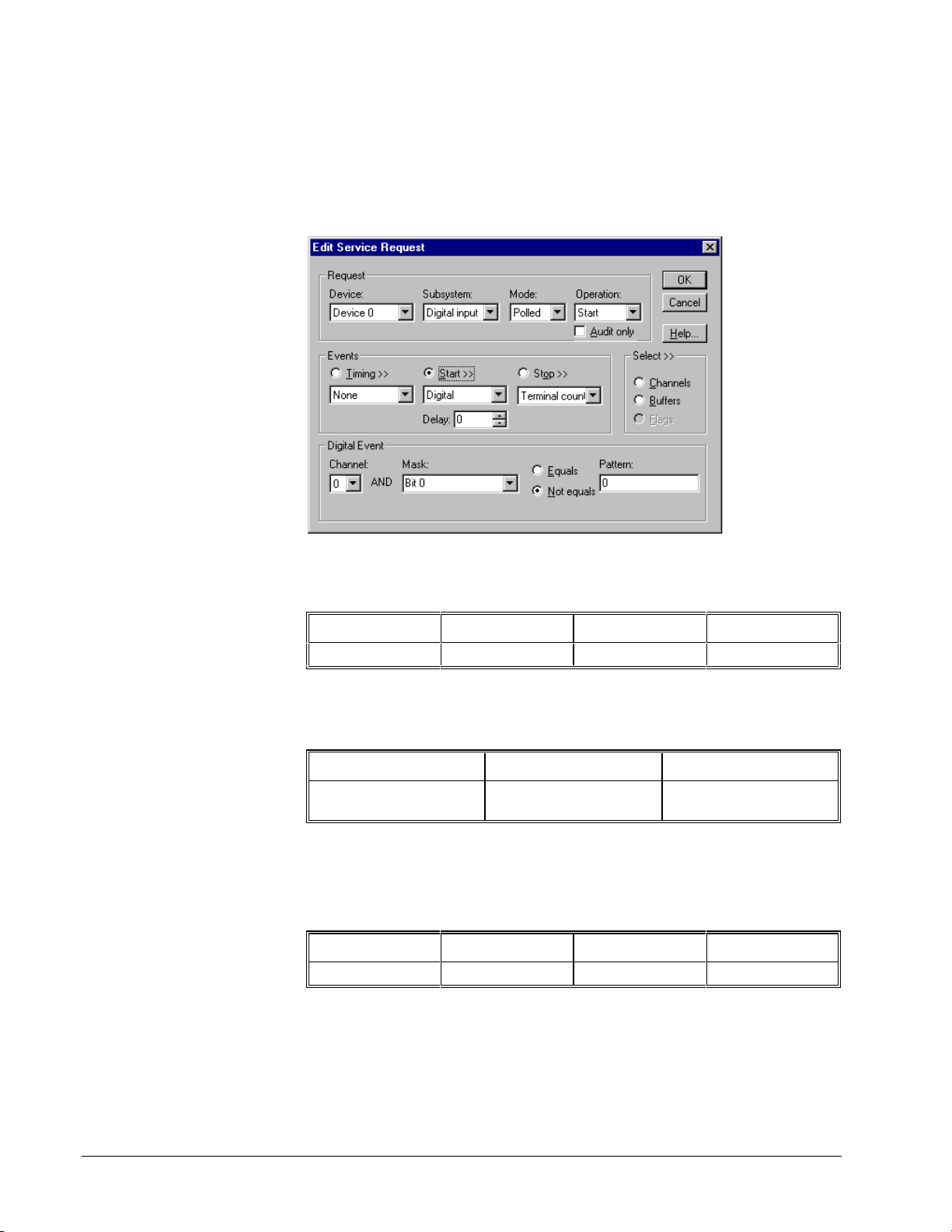
Reading or Writing Specific Digital Bits
Applications can write specific bits to a digital port using a Digital E vent to supply a
bit mask. Use this technique to set single bits in an output port or to share an output
port between threads or processes.
Setting up masked I/O is similar to single value transfers. First, set up the Request
Group as follows:
Device Subsystem Mode Operation
<Logical Device> <Digital Subsystem> POLLED START
Set up the Events Group as follows:
Timing Start Stop
None Digital None or
Terminal Count
For a Stop Event, None or Terminal Count are equivalent.
Start Event
Set up the Digital Event as follows:
Channel Mask Match Pattern
<Logical Channel> <bit mask> <unused > <unused>
DriverLINX composes the new output value for the port as
new value = (old value AND NOT Mask) OR (user value AND Mask).
72 • Programming Counter/Timers with DriverLINX DriverLINX Counter/Timer User’s Guide
Page 73

Select Channels
Set up the Select Group Channels as follows:
Number of channels Start Channel Format
1 <Logical Channel> native
Select Buffers
Single-value transfers use ioValue property in the Service Request instead of a buffer
to hold the data. Set the number of Buffers to zero. For output, assign the value to
write to the ioValue property in the Results Group. For input, read the input from the
ioValue property after executing the Service Request.
To write a single value, set up the Status Group of the Service Request as follows:
Type ioValue
IOVALUE <value>
Write a Masked Value Using C/C++
//*****************************************************
// Use this procedure to read one value from a specific
// channel
//*****************************************************
UINT WriteBits (LPServiceRequest pSR, UINT Device, UINT Channel, UINT
Value, UINT Mask)
{
memset(pSR, 0, sizeof(DL_SERVICEREQUEST));
DL_SetServiceRequestSize(*pSR);
pSR->hWnd = GetSafeHwnd();
pSR->device = Device;
pSR->subsystem = DO;
pSR->mode = POLLED;
pSR->operation = START;
pSR->start.typeEvent = DIEVENT;
pSR->start.u.diEvent.channel = Channel;
pSR->start.u.diEvent.mask = Mask;
pSR->start.u.diEvent.match = FALSE;
pSR->start.u.diEvent.pattern = 0;
pSR->channels.nChannels = 1;
pSR->channels.chanGain[0].channel = Channel;
pSR->status.typeStatus = IOVALUE;
pSR->status.u.ioValue = Value;
return DriverLINX(pSR);
}
DriverLINX Counter/Timer User’s Guide Programming Counter/Timers with DriverLINX • 73
Page 74

Write a Masked Value Using Visual Basic
Function WriteBits(dl As DriverLINXSR, ByVal Channel As Integer, ByVal
Value As Integer, ByVal Mask As Integer)As Integer
’ Set up for polled digital output of 1 sample
With dl
.Req_subsystem = DL_DO
.Req_mode = DL_POLLED
.Req_op = DL_START
.Evt_Tim_type = DL_NULLEVENT
.Evt_Str_type = DL_DIEVENT
.Evt_Str_diChannel = Channel
.Evt_Str_diMask = Mask
.Evt_Str_diMatch = DL_NotEquals
.Evt_Str_diPattern = 0
.Evt_Stp_type = DL_NULLEVENT
.Sel_buf_N = 0
.Sel_chan_format = DL_tNATIVE
.Sel_chan_N = 1
.Sel_chan_start = Channel
.Res_Sta_ioValue = Value
.Refresh
WriteBits = .Res_result
End With
End Function
74 • Programming Counter/Timers with DriverLINX DriverLINX Counter/Timer User’s Guide
Page 75

Rapidly Transferring a Block of Digital Data
Applications can rapidly transfer a single data buffer of values to or from a digital
I/O port using the computer’s block I/O hardware instructions. Note that not all
hardware boards are able to sustain the I/O transfer rate on faster computers.
To transfer a buffer, set up the Request Group as follo ws:
Device Subsystem Mode Operation
<Logical Device> <Logical
Subsystem>
POLLED START
Set up the Events Group as follows:
Timing Start Stop
None None or
Command
None or
Terminal Count
For a Start Event, None and Command are equivalent for a Start Event as are None
and Terminal Count for a Stop Event. Start on Command and stop on Terminal
Count tells DriverLINX to transfer the data in buffer once.
Select Channels
Set up the Select Group Channels as follows:
Number of channels Start Channel Format
1 <Logical Channel> native
DriverLINX Counter/Timer User’s Guide Programming Counter/Timers with DriverLINX • 75
Page 76

Select Buffers
Set the number of Buffers to one and the BufferSize to the number of bytes to
transfer.
Read or Write a Single Buffer Using C/C++
Read One Buffer
//**********************************
// Use this procedure to read a data
// array from a specific channel
//**********************************
UINT ReadChannelBuff (LPServiceRequest pSR, UINT Device, UINT Channel,
PVOID Buffer, DWORD Length)
{
memset(pSR, 0, sizeof(DL_SERVICEREQUEST));
DL_SetServiceRequestSize(*pSR);
pSR->hWnd = GetSafeHwnd();
pSR->device = Device;
pSR->subsystem = DI;
pSR->mode = POLLED;
pSR->operation = START;
pSR->channels.nChannels = 1;
pSR->channels.chanGain[0].channel = Channel;
pSR->lpBuffers = (LPBUFFLIST)malloc(DL_BufferListBytes(1));
// N.B. Caller must deallocate buffer list memory
if (!pSR->lpBuffers)
return Error(Abort, BufAllocErr);
pSR->lpBuffers->nBuffers = 1;
pSR->lpBuffers->bufferSize = Length;
pSR->lpBuffers->BufferAddr[0] = Buffer;
return DriverLINX(pSR);
}
76 • Programming Counter/Timers with DriverLINX DriverLINX Counter/Timer User’s Guide
Page 77

Write One Buffer
//***********************************
// Use this procedure to write a data
// array to a specific channel
//***********************************
UINT WriteChanBuf (LPServiceRequest pSR, UINT Device, UINT Channel,
PVOID Buffer, DWORD Length)
{
memset(pSR, 0, sizeof(DL_SERVICEREQUEST));
DL_SetServiceRequestSize(*pSR);
pSR->hWnd = GetSafeHwnd();
pSR->device = Device;
pSR->subsystem = DO;
pSR->mode = POLLED;
pSR->operation = START;
pSR->channels.nChannels = 1;
pSR->channels.chanGain[0].channel = Channel;
pSR->lpBuffers = (LPBUFFLIST)malloc(DL_BufferListBytes(1));
if (!pSR->lpBuffers)
return Error(Abort, BufAllocErr);
pSR->lpBuffers->nBuffers = 1;
pSR->lpBuffers->bufferSize = Length;
pSR->lpBuffers->BufferAddr[0] = Buffer;
UINT result;
result = DriverLINX(pSR);
if (pSR->lpBuffers) {
free(pSR->lpBuffers);
pSR->lpBuffers = 0;
}
return result;
}
DriverLINX Counter/Timer User’s Guide Programming Counter/Timers with DriverLINX • 77
Page 78

Read or Write a Single Buffer Using Visual Basic
Read One Buffer
’ Use this procedure to read one buffer from a
’ specific channel.
Function ReadChannelBuff(dl As DriverLINXSR, ByVal Channel As Integer,
Buffer() As Byte, ByVal Length As Integer)As Integer
’ Set up for polled digital input
With dl
.Req_subsystem = DL_DI
.Req_mode = DL_POLLED
.Req_op = DL_START
.Evt_Tim_type = DL_NULLEVENT
.Evt_Str_type = DL_NULLEVENT
.Evt_Stp_type = DL_NULLEVENT
.Sel_buf_N = 1
.Sel_buf_size = dl.DLSamples2Bytes(Channel, Length)
.Sel_chan_format = DL_tINTEGER
.Sel_chan_N = 1
.Sel_chan_start = Channel
.Refresh
ReadChannelBuff = .Res_result
End With
If dl.Res_result = DL_NoErr Then
Dim dummy As Integer
dummy = .VBArrayBufferXfer(0, Buffer, DL_BufferToVBArray)
End If
End Function
Write One Buffer
’ Use this procedure write an integer data
’ array to a specific channel
Function WriteChanBuf(dl As DriverLINXSR, ByVal Channel As Integer,
Buffer() As Byte, ByVal Length As Integer)As Integer
Dim I As Integer, dummy As Integer
With dl
.Req_subsystem = DL_DO
.Req_mode = DL_POLLED
.Req_op = DL_START
.Evt_Tim_type = DL_NULLEVENT
.Evt_Str_type = DL_NULLEVENT
.Evt_Stp_type = DL_NULLEVENT
.Sel_buf_N = 1
.Sel_buf_size = dl.DLSamples2Bytes(Channel, Length)
dummy = .VBArrayBufferXfer(0, Buffer, DL_VBArrayToBuffer)
.Sel_chan_format = DL_tNATIVE
.Sel_chan_N = 1
.Sel_chan_start = Channel
.Refresh
WriteChanBuf = .Res_result
End With
End Function
78 • Programming Counter/Timers with DriverLINX DriverLINX Counter/Timer User’s Guide
Page 79
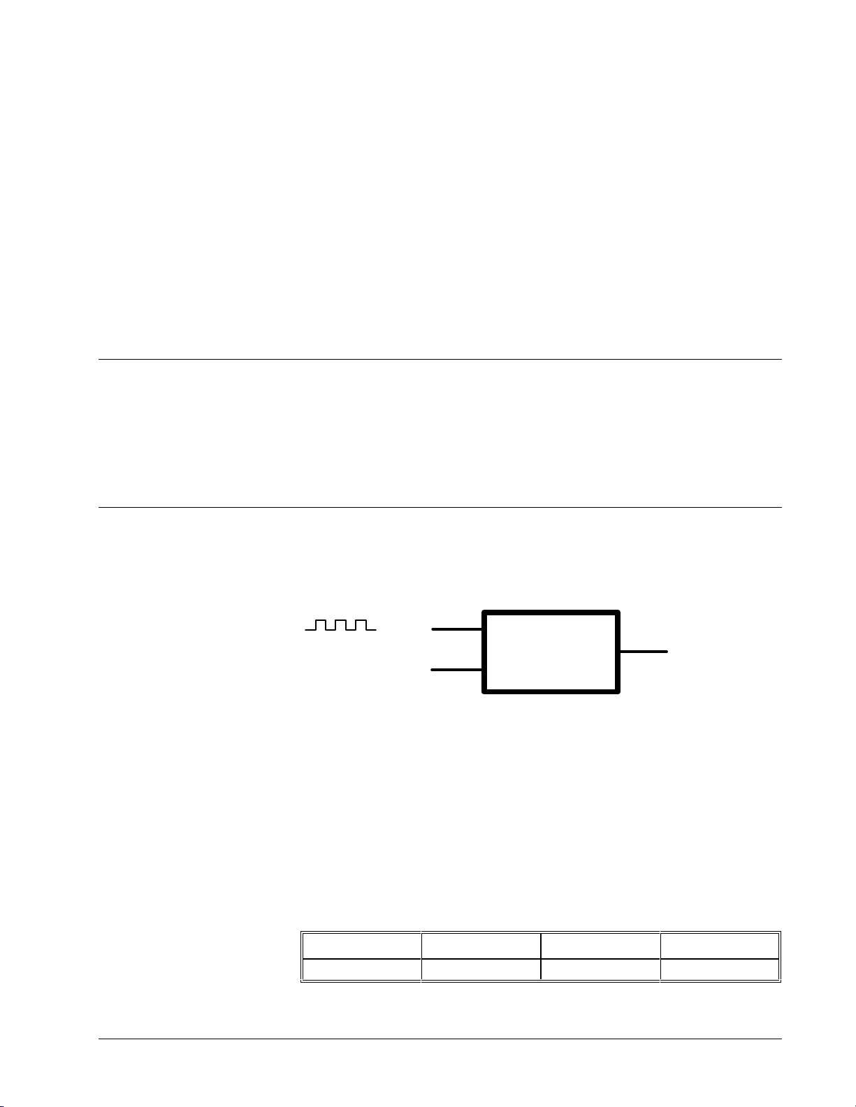
Using Task-Oriented Functions
DriverLINX’s Task-Oriented Functions
DriverLINX defines several useful task-oriented counter/timer function s tha t can be
support on most counter/timer hardware. These tasks define common counter/timer
functions in generic terms so they are portable acro ss data-acquisition boards with
similar features. Using one of these tasks makes your ap plication independent of the
particular counter/timer chip a board uses.
Event Counting
Event counting is the simplest counter/timer function. The counter/timer counts
source edges at the Clock input and the application reads the current count value. In
polled mode, the application reads the count value by using Status commands.
Each Am9513 chip has five
counter/timer channels. When
advancing to the next higher
channel, the hardware wraps
around from the last to first
channel.
Clock
Event
Gate
Figure 2 Event Counting
DriverLINX supports 16-, 32-, and 64-bit wide counters using 1, 2, or 4
counter/timer channels, respectively. When using multiple counter/timer channels,
the application’s Service Request specifies the counter/timer channel where the user
has attached the input source, and DriverLINX then automatically uses consecutive
counter/timer channels for the high-order count.
Counter
Output
Starting an Event Counter
To start a software-polled event counter, set up the Request Group as follows:
Device Subsystem Mode Operation
<Logical Device> CT POLLED START
DriverLINX Counter/Timer User’s Guide Using Task-Oriented Functions • 79
Page 80

Set up the Events Group as follows:
Timing Start Stop
Rate None or
Command
To set up the Timing Event, see “Specifying the Rate Event for Event Counting” on
page 80. DriverLINX does not need Start or Stop events for event counting, but the
application may optionally specify Command and Terminal Count for Start and Stop
events, respectively. For a Service Request that does not specify data buffers, None
and Command are equivalent for a Start Event as are None and Terminal Count for a
Stop Event.
None or
Terminal Count
Specifying the Rate Event for Event Counting
You can determine the first
overflow by physically
connecting a toggled Output
to a digital input and polling
the digital input.
DriverLINX’s default output
value for all event counters is
active-high terminal count
pulse.
DriverLINX supports repetitive and non-repetitive event counting with several
gating options as shown in the following tables for 16-, 32-, and 64-bit counting.
When repetitive counters reach the maximum count, they wrap around to zero and
continue counting without any indication of overflow. When non-repetitive counters
reach the maximum count, they wrap around to zero and stop with a count of one.
To set up an event counter, select the type of counter from the following tables and
program the Rate Generator properties in a Service Request as specified. Unused or
unspecified properties should be set to zero. Applications can set the Rate
Generator’s Output property to any val ue. See “Counter Output” on page 55.
Am9513
In the following tables, the Am9513 Mode column refers to the Advanced Micro
Devices’ letter designation for the hardware mode that DriverLINX uses to
implement the counter functio n. See “Am9513 Operating Modes” on page 117 for
information about hardware modes.
80 • Using Task-Oriented Functions DriverLINX Counter/Timer User’s Guide
Page 81

16-bit
Counting
Repetitive
counting
with no
hardware
gating
Nonrepetitive
counting
with no
hardware
gating
Repetitive
counting
with level
gating
Nonrepetitive
counting
with level
gating
Repetitive
counting
with edge
triggering
Nonrepetitive
counting
with edge
triggering
Repetitive
counting
with
hardware
retriggering
Am9513
Mode
D N COUNT <source> DISABLED 0
A N COUNT <source> DISABLED 1
E N COUNT <source> level 0
B N COUNT <source> level 1
F N COUNT <source> edge 0
C N COUNT <source> edge 1
Q N RETRIG
Channel Mode Clock Gate Pulses
<source> level 0
COUNT
Table 16 Rate Event Properties for 16-bit Event Counting
DriverLINX Counter/Timer User’s Guide Using Task-Oriented Functions • 81
Page 82

32-bit
Counting
Repetitive
counting
with no
hardware
gating
Nonrepetitive
counting
with no
hardware
gating
Repetitive
counting
with level
gating
Table 17 Rate Event Properties for 32-bit Event Counting
Am9513
Channel Mode Clock Gate Pulses
Mode
D, D N..N+1 COUNT32 <source> DISABLED 0
D, A N. . N +1 COUNT32 <so urce> DISABLED 1
E, D N..N+1 COUNT32 <source> level 0
64-bit
Counting
Repetitive
counting
with no
hardware
gating
Am951
Channel Mode Clock Gate Pulses
3 Mode
D, D, D, D N..N+3 COUNT64 <source> DISABLED 0
Table 18 Rate Event Properties for 64-bit Event Counting
KPCI-3140
In the following tables, the KPCI-3140 Mode column refers to the hardware mode
that DriverLINX uses to implement the counter function. See “KPCI-3140 Operating
Modes” on page 116 for information about hardware modes.
82 • Using Task-Oriented Functions DriverLINX Counter/Timer User’s Guide
Page 83

16-bit
0
0
0
Counting
Repetitive
counting
with no
hardware
gating
Nonrepetitive
counting
with no
hardware
gating
Repetitive
counting
with level
gating
Nonrepetitive
counting
with edge
triggering
Table 19 Rate Event Properties for 16-bit Event Counting
KPCI-314
Channel Mode Clock Gate Pulses
Mode
2 N COUNT <source> DISABLED 0
0 N COUNT <source> DISABLED 1
2 N COUNT <source> level 0
0 N COUNT <source> edge 1
32-bit
Counting
Repetitive
counting
with no
hardware
gating
Repetitive
counting
with level
gating
KPCI-314
Channel Mode Clock Gate Pulses
Mode
2, 2 N..N+1 COUNT32 <source> DISAB LED 0
2, 2 N..N+1 COUNT32 <source> level 0
Table 20 Rate Event Properties for 32-bit Event Counting
64-bit
Counting
Repetitive
counting
with no
hardware
gating
Repetitive
counting
with level
gating
Table 21 Rate Event Properties for 64-bit Event Counting
DriverLINX Counter/Timer User’s Guide Using Task-Oriented Functions • 83
KPCI-314
Channel Mode Clock Gate Pulses
Mode
2, 2, 2, 2 N..N+3 COUNT64 <sour ce> DISABLED 0
2, 2, 2, 2 N..N+3 COUNT64 <source> level 0
Page 84

Hardware Setup for Event Counting
The Am9513 supports
counting any source or gate
input as well as the previous
counter’s terminal count and
the internal frequency divider.
For event counting, the application specifies the Logical Channel, N, of the base
counter in the Service Request. The user attaches the count source to the terminal the
application specifies in the Service Request Clock property. Depending on the
counting Mode, the user optionally attaches a triggering or gating signal to the Gate
input.
Channel Clock Gate Output
N count source see tables
N+m any
When using multiple counter/timer channels, the application’s Service Request
specifies the base counter/timer, and DriverLINX then automatically uses
consecutive counter/timer channels for the higher-order count.
Event Counting Using C/C++
//**************************************
// Use this procedure for event counting
//**************************************
UINT StartEventCount (LPServiceRequest pSR, UINT LogicalDevice,
UINT LogicalChannel, CLOCKS source,
GATESTATUS gate, UINT clkOut,
BOOLEAN continuous)
{
// Set up Service Request to perform task
// First zero Service Request structure
memset(pSR, 0, sizeof(DL_SERVICEREQUEST));
// Then initialize structure size
DL_SetServiceRequestSize(*pSR);
// Set up Request Group of Service Request
pSR->hWnd = GetSafeHwnd();
pSR->device = LogicalDevice;
pSR->subsystem = CT;
pSR->mode = POLLED;
pSR->operation = START;
// Set up Timing Event
pSR->timing.typeEvent = RATEEVENT;
pSR->timing.u.rateEvent.channel = LogicalChannel;
pSR->timing.u.rateEvent.mode = COUNT; // or COUNT32 or COUNT64
pSR->timing.u.rateEvent.clock = source;
pSR->timing.u.rateEvent.gate = gate;
pSR->timing.u.rateEvent.period = 0;
pSR->timing.u.rateEvent.onCount = 0;
pSR->timing.u.rateEvent.pulses = continuous ? 0 : 1;
pSR->timing.u.rateEvent.pulses |= clkOut;
// Call DriverLINX to perform Service Request
return DriverLINX(pSR);
}
84 • Using Task-Oriented Functions DriverLINX Counter/Timer User’s Guide
Page 85

Event Counting Using Visual Basic
’**************************************
’ Use this procedure for event counting
’**************************************
Function StartEventCount (dl As DriverLINXSR, ByVal LogicalDevice As
Integer, ByVal LogicalChannel As Integer, ByVal source As Integer,
ByVal gate As Integer, ByVal clkOut As Integer, ByVal continuous As
Integer) As Integer
’ Set up Service Request to perform task
With dl
.Req_device = LogicalDevice
.Req_subsystem = DL_CT
.Req_mode = DL_POLLED
.Req_op = DL_START
.Evt_Tim_type = DL_RATEEVENT
.Evt_Tim_rateChannel = LogicalChannel
.Evt_Tim_rateMode = DL_COUNT ’ or DL_COUNT32 or DL_COUNT64
.Evt_Tim_rateClock = source
.Evt_Tim_rateGate = gate
.Evt_Tim_ratePeriod = 0
.Evt_Tim_rateOnCount = 0
If continuous Then
.Evt_Tim_ratePulses = 0
Else
.Evt_Tim_ratePulses = 1
End If
.Evt_Tim_rateOutput = clkOut
’ Other events, buffers, channels unneeded
.Evt_Str_type = DL_NULLEVENT
.Evt_Stp_type = DL_NULLEVENT
.Sel_buf_N = 0
.Sel_chan_N = 0
.Refresh
StartEventCount = .Res_result
End With
End Function
Frequency Measurement
DriverLINX can measure the time-averaged frequency of an unknown frequency
source connected to the Clock input. Frequency measurement requires two or more
counter/timers configured as gating and measurement counters.
Clock
Internal
Clock
Unknown
Frequency
Figure 3 Frequency Measurement
The measurement counter counts the unknown frequency at its Clock input for a
time interval defined by the gating counter. DriverLINX clocks the gating counter
Gate
Clock
Gate
Gating
Counter
User must add this jumper
Measurement
Counter
Output
Output
DriverLINX Counter/Timer User’s Guide Using Task-Oriented Functions • 85
Page 86

from an internal crystal reference oscillator to produce a precise counting duration.
Applications can calculate the unknown input frequency as
It is the application’s
responsibility to select the
gating interval.
frequency
where measurementCount is the counter value DriverLINX reads from the
measurement counter, gatingCount is the counter value the application specifies for
the measurement interval in the Service Request, and clockPeriod is the duration of
the reference oscillator’s period. See “Converting Between Co unts and Time” on
page 58 for how to convert a count to sec onds.
The accuracy of the measurement is a function of the unknown input frequency and
the gating interval. As the input frequency decreases, the gating interval should
increase to preserve accuracy. To measure a 0.1 Hz signal, the gating interval should
be approximately 3 minutes.
Usage Notes
Use of this function is hi ghly dependent on hardware features. Some mod els cannot
stop nor latch counts in this mode so the results may be invalidated by counter
rollover. This means that, on such hardware, a STATUS oper ation is required to
sample the measurement counter after the first gate pulse but before the next.
Depending on the clock frequency and counter width, the va lid sample window can
be very short.
=
gatingCount clockPeriod
×
Starting a Frequency Counter
To start a software-polled frequency counter, set up the Service Request Group as
follows:
measurementCount
Device Subsystem Mode Operation
<Logical Device> CT POLLED START
Set up the Events Group as follows:
Timing Start Stop
Rate None or
Command
See “Specifying the Rate Event for Frequency Measurements” on page 87 for how to
assign the properties of a Rate Event. DriverLINX does not need Start or Stop events
for frequency measurements, but the application may optionally specif y Command
and Terminal Count for Start and Stop events, respectively. For a Service Request
that does not specify buffers, None and Command are equivalent for a Start Event as
are None and Terminal Count for a Stop Event.
None or
Terminal Count
86 • Using Task-Oriented Functions DriverLINX Counter/Timer User’s Guide
Page 87

Specifying the Rate Event for Frequency
f
j
Measurements
Each Am9513 chip has five
counter/timer channels. When
advancing to the next higher
channel, the hardware wraps
around from the last to first
channel.
The KPCI-3140 chip cannot
wrap around from the last to
irst.
The user must install a
umper to perform frequency
measurements. See
“Hardware Setup for
Frequency Measurement” on
page 89.
DriverLINX supports 16- and 32-bit frequency measurements using multiple
counter/timer channels. DriverLINX uses one counter (on the Am9513) or two
counters (on the KPCI-3140) for the gating counter and one or two counters for the
measurement counter. When using multiple counter/timer channels, the application
specifies the Logical Channel of the first gating counter in the Service Request a nd
DriverLINX automatically uses consecutive counter/timer channels for the
measurement counter(s). The user may attach the unknown input source to any
Clock or Gate input that DriverLINX allows for the Clock property.
DriverLINX supports repetitive (Pulses property = 0) and non-repetitive (Pulses
propert y = 1) frequenc y measurement with several gating options as sho wn in the
following tables for 16- and 32-bit frequency measurement. Repetitive counters
continually repeat the frequency measurement. Non-repetitive counters measure one
input cycle and then stop measuring.
To set up a frequency measurement, select the type of measurement from the
following tables and program the Rate Generator properties in a Service Request as
specified. The OnCount property specifies the gating interval while the Period
property should be zero. Other unused or unspecified properties should be set to
zero. Applications can set the Rate Generator’s Output property to any value. See
“Counter Output” on page 55.
Am9513
The Am9513 Mode column in the follo wing tables refers to the Advanced Micro
Devices’ letter designation for the hardware modes that DriverLINX uses to
implement the counter functio n. See “Am9513 Operating Modes” on page 117 for
information about hardware modes.
16-bit
Frequency
AM9513
Mode
Channel Mode Clock Gate Pulses
Measurement
Repetitive
measurement
with no hardware
gating
Non-repetitive
measurement
with no hardware
gating
Repetitive
measurement
with edge
triggering
Non-repetitive
measurement
with edge
triggering
Table 22 Rate Event Properties for 16-bit Frequency Measurement
J, Q N..N+1 FREQ <source> DISABLED 0
G, Q N. .N+1 FREQ <source> DISABLED 1
L, Q N..N+1 FREQ <source> EDGE 0
I, Q N..N+1 FREQ <source> EDGE 1
DriverLINX Counter/Timer User’s Guide Using Task-Oriented Functions • 87
Page 88

0
0
32-bit
Frequency
Am9513
Mode
Channel Mode Clock Gate Pulses
Measurement
Repetitive
measurement
with no hardware
gating
Non-repetitive
measurement
with no hardware
gating
Repetitive
measurement
with edge
triggering
Non-repetitive
measurement
with edge
triggering
Table 23 Rate Event Properties for 32-bit Frequency Measurement
G, E, D N..N+2
G, E, D N..N+2
I, E, D N..N+2
I, E, D N..N+2
FREQ3
2
FREQ3
2
FREQ3
2
FREQ3
2
<source> DISABLED 0
<source> DISABLED 1
<source> EDGE 0
<source> EDGE 1
KPCI-3140
The KPCI-3140 Mode column refers to the hardware modes that DriverLINX uses to
implement the counter function. See “KPCI-3140 Operating Modes” on page 116 for
information about hardware modes.
16-bit
Frequency
KPCI-314
Mode
Channel Mode Clock Gate Pulses
Measurement
Non-repetitive
measurement
with no hardware
gating
Non-repetitive
measurement
with level gating
Table 24 Rate Event Properties for 16-bit Frequency Measurement
2, 1
2
2, 1
2
N..N+2 FREQ <source> DISABLED 1
N..N+2 FREQ <source> level 1
32-bit
Frequency
KPCI-314
Mode
Channel Mode Clock Gate Pulses
Measurement
Non-repetitive
measurement
with no hardware
gating
Non-repetitive
measurement
with level gating
2, 1
2, 2
2, 1
2, 2
N..N+3
N..N+3
FREQ32
FREQ32
<source> DISABLED 1
<source> level 1
88 • Using Task-Oriented Functions DriverLINX Counter/Timer User’s Guide
Page 89

Table 25 Rate Event Properties for 32-bit Frequency Measurement
Hardware Setup for Frequency Measurement
For frequency measurement, the application specifies the Logical Channel, N, of the
gating counter in the Service Request. The user attaches the unknown frequency
signal to the terminal the application specifies in the Service Request Clock property.
Depending on the counting Mode, the user optionally attaches a signal to the Gate
input.
Before performing a frequency measurement, the user must physically attach a
connection between the
N, and the
Gate
terminal of the first measurement counter, Logical Channel N+m.
Output
Channel Clock Gate Output
N (first gating
counter)
N+m (first
measurement
counter)
N+m+ n (last
measurement
counter)
see tables
unknown source
any
terminal of the last gating counter, Logical Channel
When using multiple counter/timer channels, the application’s Service Request
specifies the first gating counter/timer, and DriverLINX then automatically uses
consecutive counter/timer channels for next gating counter, if any, and the
measurement counter(s).
DriverLINX Counter/Timer User’s Guide Using Task-Oriented Functions • 89
Page 90

Frequency Measurement Using C/C++
//*********************************************
// Use this procedure for frequency measurement
//*********************************************
UINT StartFrequencyMeasurement (LPServiceRequest pSR,
UINT LogicalDevice,
UINT LogicalChannel, CLOCKS source,
GATESTATUS gate, ULONG measure,
UINT clkOut,
BOOLEAN continuous)
{
// Set up Service Request to perform task
// First zero Service Request structure
memset(pSR, 0, sizeof(DL_SERVICEREQUEST));
// Then initialize structure size
DL_SetServiceRequestSize(*pSR);
// Set up Request Group of Service Request
pSR->hWnd = GetSafeHwnd();
pSR->device = LogicalDevice;
pSR->subsystem = CT;
pSR->mode = POLLED;
pSR->operation = START;
// Set up Timing Event
pSR->timing.typeEvent = RATEEVENT;
pSR->timing.u.rateEvent.channel = LogicalChannel;
pSR->timing.u.rateEvent.mode = FREQ; // or FREQ32
pSR->timing.u.rateEvent.clock = source;
pSR->timing.u.rateEvent.gate = gate;
pSR->timing.u.rateEvent.period = 0;
pSR->timing.u.rateEvent.onCount = measure;
pSR->timing.u.rateEvent.pulses = continuous ? 0 : 1;
pSR->timing.u.rateEvent.pulses |= clkOut;
// Call DriverLINX to perform Service Request
return DriverLINX(pSR);
}
90 • Using Task-Oriented Functions DriverLINX Counter/Timer User’s Guide
Page 91

Frequency Measurement Using Visual Basic
’*********************************************
’ Use this procedure for frequency measurement
’*********************************************
Function StartFrequencyMeasurement (dl As DriverLINXSR, ByVal
LogicalDevice As Integer, ByVal LogicalChannel As Integer, ByVal source
As Integer, ByVal gate As Integer, ByVal measure as Long, ByVal clkOut
As Integer, ByVal continuous As Integer) As Integer
’ Set up Service Request to perform task
With dl
.Req_device = LogicalDevice
.Req_subsystem = DL_CT
.Req_mode = DL_POLLED
.Req_op = DL_START
.Evt_Tim_type = DL_RATEEVENT
.Evt_Tim_rateChannel = LogicalChannel
.Evt_Tim_rateMode = DL_FREQ ’ or DL_FREQ32
.Evt_Tim_rateClock = source
.Evt_Tim_rateGate = gate
.Evt_Tim_ratePeriod = 0
.Evt_Tim_rateOnCount = measure
If continuous Then
.Evt_Tim_ratePulses = 0
Else
.Evt_Tim_ratePulses = 1
End If
.Evt_Tim_rateOutput = clkOut
’ Other events, buffers, channels unneeded
.Evt_Str_type = DL_NULLEVENT
.Evt_Stp_type = DL_NULLEVENT
.Sel_buf_N = 0
.Sel_chan_N = 0
.Refresh
StartFrequencyMeasurement = .Res_result
End With
End Function
DriverLINX Counter/Timer User’s Guide Using Task-Oriented Functions • 91
Page 92

Interval Measurement
DriverLINX can measure the time interval between two consecutive pulses using
two techniques. In one technique, DriverLINX measures the time delay between two
pulses connected to different counters. In the other technique, DriverLINX measures
the delay between two pulses attached to the input of one counter.
Clock
Internal
Gate
Pulse 1
Interval
Counter
Output
Clock
Internal
Gate
Pulse 2
Figure 4 Interval Measurement on Two Channels
Interval
Counter
Output
Clock
Internal
Gate
Pulse 1 & 2
Figure 5 Interval Measurement on One Channel
Usage Notes
Use of this function is hi ghly dependent on hardware features. Some hardware
models support only single-input interval measurement, while other model support
only dual-input interval measurement.
Interval
Counter
Output
Also, some models cannot stop nor latch counts in this mode so subseq uent pulses or
counter rollover may invalidate the results. This means that, on such hardware, a
STATUS operation is required to sample the counters a fter b oth pulses but before
counter rollover. Depending on the clock freq uency and pu lse timing, the valid
sample window can be very short.
Starting an Interval Counter
To start a software-polled interval counter, set up the Reque st Gr oup as follows:
Device Subsystem Mode Operation
<Logical Device> CT POLLED START
92 • Using Task-Oriented Functions DriverLINX Counter/Timer User’s Guide
Page 93

Set up the Events Group as follows:
Service Request as specified in the following table. Unused or unspecified properties
Timing Start Stop
Rate None or
Command
None or
Terminal Count
See “Specifying the Rate Event for Interval Measurements” on page 93 for how to
assign the properties of a Rate Event. DriverLINX does not need Start or Stop events
for interval measurements, but the application may optio nally specify Command and
Terminal Count for Start and Stop events, respectively. For a Service Request that
does not specify buffers, None and Command are equivalent for a Start Event as are
None and Terminal Count for a Stop Event.
Specifying the Rate Event for Interval
Measurements
DriverLINX supports 16-bit interval measurements using 1 or 2 counter/timer
channels. When using a single input, DriverLINX measures the interval between two
consecutive pulse edges connected to the Gate input. When dual inputs for interval
measurements, DriverLINX measures the interval between pulse edges connected to
the Gate inputs of each counter.
• To specify dual input interval measurements, the application specifies
the first Logical Channel as the timing Logical Channel and specifies
the second Logical Channel in the Period property of the Rate Event.
Repetitive counters
continually repeat the interval
measurement. Non-repetitive
counters measure one input
pair and then stop counting.
• To specify single input measurements, the application should set the
Period property to the same value as the Channel property.
The Clock property must specify one of the internal clock sources. The internal clock
period times 65536 determi nes the longest interval between two pulses that the
hardware can measure.
To set up an interval measurement, program the Rate Generator properties in a
should be set to zero. Applications can set the Rate Generato r ’s Output property to
any value. See “Counter Output” on page 55.
Am9513
The Am9513 Mode column in the follo wing tables refers to the Advanced Micro
Devices’ letter designation for the hardware mode that DriverLINX uses to
implement the counter functio n. See “Am9513 Operating Modes” on page 117 for
information about hardware modes.
16-bit Interval
Measurement
Repetitive (single
input)
measurement
Table 26 Rate Event Properties for 16-bit Interval Measurements
AM9513
Mode
R N INTERVAL <source> N 0
Channel Mode Clock Period Pulses
DriverLINX Counter/Timer User’s Guide Using Task-Oriented Functions • 93
Page 94

Hardware Setup for Interval Measurements
For interval measurements, the application specifies the Logical Channel(s) of the
input counter(s) in the Service Request. The user attaches the unknown pulse
signal(s) to the Gate inputs of the channel(s) the user specified. The application can
program the counter/timer to measure the delay between the rising or falling edges of
the pulses.
Interval Measurement Using C/C++
//*********************************************
// Use this procedure for interval measurements
//*********************************************
UINT StartIntervalMeasurement (LPServiceRequest pSR,
UINT LogicalDevice,
UINT LogicalChannel1,
UINT LogicalChannel2, CLOCKS source,
GATESTATUS gate,
UINT clkOut)
{
// Set up Service Request to perform task
// First zero Service Request structure
memset(pSR, 0, sizeof(DL_SERVICEREQUEST));
// Then initialize structure size
DL_SetServiceRequestSize(*pSR);
// Set up Request Group of Service Request
pSR->hWnd = GetSafeHwnd();
pSR->device = LogicalDevice;
pSR->subsystem = CT;
pSR->mode = POLLED;
pSR->operation = START;
// Set up Timing Event
pSR->timing.typeEvent = RATEEVENT;
pSR->timing.u.rateEvent.channel = LogicalChannel1;
pSR->timing.u.rateEvent.mode = INTERVAL;
pSR->timing.u.rateEvent.clock = source;
pSR->timing.u.rateEvent.gate = gate;
pSR->timing.u.rateEvent.period = LogicalChannel2;
pSR->timing.u.rateEvent.onCount = 0;
pSR->timing.u.rateEvent.pulses =
LogicalChannel1 == LogicalChannel2 ? 0 : 1;
pSR->timing.u.rateEvent.pulses |= clkOut;
// Call DriverLINX to perform Service Request
return DriverLINX(pSR);
}
94 • Using Task-Oriented Functions DriverLINX Counter/Timer User’s Guide
Page 95

Interval Measurement Using Visual Basic
’*********************************************
’ Use this procedure for interval measurements
’*********************************************
Function StartIntervalMeasurement (dl As DriverLINXSR, ByVal
LogicalDevice As Integer, ByVal LogicalChannel1 As Integer, ByVal
LogicalChannel2 As Integer, ByVal source As Integer, ByVal gate As
Integer, ByVal clkOut As Integer) As Integer
’ Set up Service Request to perform task
With dl
.Req_device = LogicalDevice
.Req_subsystem = DL_CT
.Req_mode = DL_POLLED
.Req_op = DL_START
.Evt_Tim_type = DL_RATEEVENT
.Evt_Tim_rateChannel = LogicalChannel1
.Evt_Tim_rateMode = DL_INTERVAL
.Evt_Tim_rateClock = source
.Evt_Tim_rateGate = gate
.Evt_Tim_ratePeriod = LogicalChannel2
.Evt_Tim_rateOnCount = 0
If LogicalChannel1 = LogicalChannel2 Then
.Evt_Tim_ratePulses = 0
Else
.Evt_Tim_ratePulses = 1
End If
.Evt_Tim_rateOutput = clkOut
’ Other events, buffers, channels unneeded
.Evt_Str_type = DL_NULLEVENT
.Evt_Stp_type = DL_NULLEVENT
.Sel_buf_N = 0
.Sel_chan_N = 0
.Refresh
StartIntervalMeasurement = .Res_result
End With
End Function
DriverLINX Counter/Timer User’s Guide Using Task-Oriented Functions • 95
Page 96

Period and Pulse Width Measurement
DriverLINX can measure the period, or duration, of a single cycle of an unknown
input.
Internal
Frequency
Clock
Gate
period
Unknown
Frequency
Figure 6 Period Measurement
DriverLINX can measure the duration of the positive or negative half-cycle of an
input.
Internal
Frequency
Clock
Gate
Period
Counter
Pulse Width
Counter
Output
Output
+width
Unknown
Frequency
Figure 7 Pulse Width Measurement
Starting an Period or Pulse Width Measurement
To start a software-polled period or pulse width measurement, set up the Service
Request Group as follows:
Device Subsystem Mode Operation
<Logical Device> CT POLLED START
Set up the Events Group as follows:
Timing Start Stop
Rate None or
Command
None or
Terminal Count
96 • Using Task-Oriented Functions DriverLINX Counter/Timer User’s Guide
Page 97

See “Specifying the Rate Event for Period and Pulse Width Measurements” on page
97 for how to assign the properties of a Rate Event. DriverLINX does not need Start
or Stop events for period and pulse width measurements, but the application may
optionally specify Command and Terminal Count for Start and Stop events,
respectively. For a Start Event, None and Command are equivalent for a Start Event
as are None and Terminal Count for a Stop Event.
Specifying the Rate Event for Period and Pulse
Width Measurements
DriverLINX supports period and pulse width measurements using one counter/timer
channel.
• To measure a period, DriverLINX times the interval between two rising
or falling edges at the Gate input. To specify a period measurement, set
the Gate property of the Rate Event to one of the edge trigger values.
• To measure a pulse width, DriverLINX times the duration of the
positive or negative half-cycle of the signal at the Gate inp ut . To
specify a pulse width measurement, set the Gate property of the Rate
Event to one of the level gating values.
The Clock property must specify one of the internal clock sources. The internal clock
period times maximum counter value determines the longest period or pulse width
that the hardware can measure.
Repetitive counters
continually repeat the interval
measurement.
To set up a period or pulse width measurement, program the Rate Gen erator
properties in a Service Request as specified in the following table. Unused or
unspecified properties should be set to zero. Applications can set the Rate
Generator’s Output property to any val ue. See “Counter Output” on page 55.
Am9513
The Am9513 Mode column in the follo wing tables refers to the Advanced Micro
Devices’ letter designation for the hardware mode that DriverLINX uses to
implement the counter functio n. See “Am9513 Operating Modes” on page 117 for
information about hardware modes.
16-bit Period
Measurement
Repetitive
measurement with
edge triggering
Table 27 Rate Event Properties for 16-bit Period Measuremen ts
16-bit Pulse
Width
Measurement
Repetitive
measurement with
level gatin g
AM9513
Mode
R N PULSEWD INTERNAL EDGE 0
AM9513
Mode
Q N PULSEWD INTERNAL LEVEL 0
Channel Mode Clock Gate Pulses
Channel Mode Clock Gate Pulses
Table 28 Rate Event Properties for 16-bit Pulse Width Measurements
DriverLINX Counter/Timer User’s Guide Using Task-Oriented Functions • 97
Page 98

KPCI-3140
0
The KPCI-3140 Mode column refers to the hardware mode that DriverLINX uses to
implement the counter function. See “KPCI-3140 Operating Modes” on page 116 for
information about hardware modes.
16-bit Pulse
Width
Measurement
Repetitive
measurement with
level gatin g
Table 29 Rate Event Properties for 16-bit Pulse Width Measurement
KPCI-314
Mode
2 N PULSEWD INTERNAL LEVEL 0
Channel Mode Clock Gate Pulses
Hardware Setup for Period and Pulse Width
Measurements
For period and pulse width measurements, the application specifies the Logical
Channel of the measurement counter in the Service Request. The user should attach
the unknown signal to the Gate input of the channel specified in the Service Request.
The application can program the counter/timer to measure the delay between the
rising or falling edges of the signal or to measure the duration of the positive or
negative hal f cycle .
98 • Using Task-Oriented Functions DriverLINX Counter/Timer User’s Guide
Page 99

Period or Pulse Width Measurements Using C/C++
//***********************************************************
// Use this procedure for period and pulse width measurements
//***********************************************************
UINT StartPeriodPulseWidthMeasurement (LPServiceRequest pSR,
UINT LogicalDevice,
UINT LogicalChannel,
CLOCKS source,
GATESTATUS gate,
UINT clkOut)
{
// Set up Service Request to perform task
// First zero Service Request structure
memset(pSR, 0, sizeof(DL_SERVICEREQUEST));
// Then initialize structure size
DL_SetServiceRequestSize(*pSR);
// Set up Request Group of Service Request
pSR->hWnd = GetSafeHwnd();
pSR->device = LogicalDevice;
pSR->subsystem = CT;
pSR->mode = POLLED;
pSR->operation = START;
// Set up Timing Event
pSR->timing.typeEvent = RATEEVENT;
pSR->timing.u.rateEvent.channel = LogicalChannel;
pSR->timing.u.rateEvent.mode = PULSEWD;
pSR->timing.u.rateEvent.clock = source;
pSR->timing.u.rateEvent.gate = gate;
pSR->timing.u.rateEvent.period = 0;
pSR->timing.u.rateEvent.onCount = 0;
pSR->timing.u.rateEvent.pulses = 0;
pSR->timing.u.rateEvent.pulses |= clkOut;
// Call DriverLINX to perform Service Request
return DriverLINX(pSR);
}
DriverLINX Counter/Timer User’s Guide Using Task-Oriented Functions • 99
Page 100

Period or Pulse Width Measurement Using Visual
Basic
’**********************************************************
’ Use this procedure for period or pulse width measurements
’**********************************************************
Function StartPeriodPulseWidthMeasurement (dl As DriverLINXSR, ByVal
LogicalDevice As Integer, ByVal LogicalChannel As Integer, ByVal source
As Integer, ByVal gate As Integer, ByVal clkOut As Integer)As Integer
’ Set up Service Request to perform task
With dl
.Req_device = LogicalDevice
.Req_subsystem = DL_CT
.Req_mode = DL_POLLED
.Req_op = DL_START
.Evt_Tim_type = DL_RATEEVENT
.Evt_Tim_rateChannel = LogicalChannel
.Evt_Tim_rateMode = DL_PULSEWD
.Evt_Tim_rateClock = source
.Evt_Tim_rateGate = gate
.Evt_Tim_ratePeriod = 0
.Evt_Tim_rateOnCount = 0
.Evt_Tim_ratePulses = 0
.Evt_Tim_rateOutput = clkOut
’ Other events, buffers, channels unneeded
.Evt_Str_type = DL_NULLEVENT
.Evt_Stp_type = DL_NULLEVENT
.Sel_buf_N = 0
.Sel_chan_N = 0
.Refresh
StartPeriodPulseWidthMeasurement = .Res_result
End With
End Function
100 • Using Task-Oriented Functions DriverLINX Counter/Timer User’s Guide
 Loading...