

Tektronix Connecting Interface Accessories to Your KPCI-3130 Series Boards Packing List PA-765 Rev. A User manual
Page 1

•
•
•
Keithley Instruments, Inc.
28775 Aurora Road
Cleveland, Ohio 44139
(440) 248-0400
Fax: (440) 248-6168
Connecting interface accessories to your KPCI-3130 Series Boards
Packing List
This document gives a brief summary of important information needed to make the analog outputs work correctly. The outputs can be individually wired in either two-wire mode or four-wire
mode. By default, the boards will operate in four-wire mode. Unless jumpers are installed by
the user, enabled outputs without remote sensing connections will go to their maximum
voltage and remain there, regardless of the programmed output value.
Which mode should you use?
For small currents or short wiring runs, there will not be a significant voltage drop in the
leads so the two-wire mode is more convenient, because only two wires must extend to
the load. Install two jumpers as described between the sense and output terminals at the
screw terminals.
For higher current loads, wiring over ten feet (three meters) or maximum accuracy, use
four-wire mode to sense the voltage directly at the load. Four wires must extend from the
terminal block to the load, two for carrying the signal and two for the remote sensing. If
the sensed voltage is not equal to the requested output, the board’s channel output will be
automatically adjusted to yield the desired voltage at the load .
Note that each channel electrically operates in four-wire mode at all times – the difference is whether the voltage is sensed at the terminal strip via jumpers or at the load by
additional lead wires. For the majority of applications, two-wire mode is satisfactory.
Since this is configured by the wiring of each channel, you can also choose to use fourwire mode only for certain outputs.
Refer to the KPCI-3130 Series User’s Manual (provided on the accompanying CD) for more
details.
CAUTION The two I/O connectors of the KPCI-3130 board, labeled “Analog”
and “Digital,” are mechanically identical. Ensure that you connect
interface accessories, and, indirectly, external circuits to the correct
I/O connector. Connecting interface accessories or external circuits
to the wrong connector may result in damage to the KPCI-3130
board, the host computer, your external circuits, or all three.
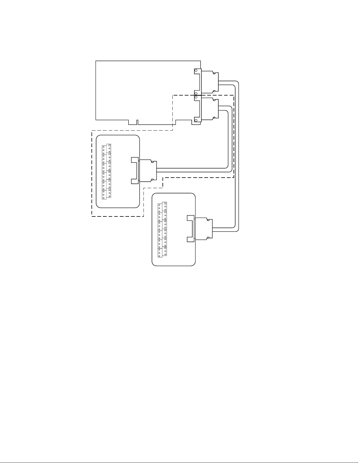
The STP-36 accessory provides basic screw terminal wiring to the I/O connector of a
KPCI-3130 Series board. All of the screw terminals are connected to the same-numbered pins of
a KPCI-3130 “Analog” or “Digital” I/O connector. Figure 1 shows how the accessory connects
to the KPCI-3130 or KPCI-3132.
PA-765 Rev. A / 12-00
Page 2
2
Figure 1
Connecting STP-36 screw terminal accessory
Analog
Output
KPCI-3130 Series Board
General
Purpose
Digital I/O
STP-36
Accessory
Digital I/O Connector
KPCI-3130 Board Only
STP-36
Accessory
Analog Out Connector
CAB-1284CC
Series Cable
CAB-1284CC
Series Cable
Making two-wire and four-wire mode connections
The KPCI-3130 Series can be configured for two-wire (local sense) or four-wire (remote sense)
mode connections. The selected mode determines whether the KPCI-3130 Series eliminates
voltage drops due to the lead wire resistance between the STP-36 and the load terminals.
NOTE
The STP-36 Screw Terminal accessory interfaces the KPCI-3130 Series
analog connector to screw terminals that are numbered identically to
the pins.
Two-wire mode (local sense)
For two-wire mode connections, the KPCI-3130 Series boards sense at the channel output and
the channel ground at the terminals of the STP-36.
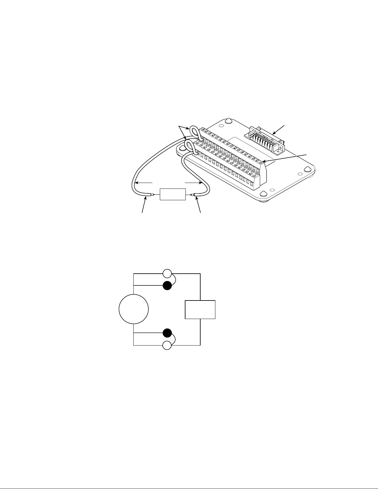
Two jumpers are required for connections in the two-wire mode. As shown in Figure 2, one
jumper is placed between Sense High and Channel Output. Another jumper is placed between
Sense Low and Channel Ground. Failure to install both of these jumpers for each channel
will result in an alarm flag for the specific channel and an overvoltage on the channel’s output if the channel is enabled. See Figure 3 for an example schematic.
Page 3
3
For example, to configure CH0 for two-wire mode:
1. Install a jumper between pins 1 and 2 of the STP-36.
2. Install a jumper between pins 19 and 20 of the STP-36.
3. Connect the load between pins 1 and 19 or pins 2 and 20 of the STP-36.
NOTE
Terminate all unused channel sense lines (Sense HI to Output Sense LO to GND/return).
Figure 2
Two-wire mode connections
Jumpers
1
2
3
19
20
IEEE-1284C Connector
17
18
35
36
Screw
Terminals
Field Wires
LOAD
+-
Ch. output wire
Figure 3
Example of a two-wire mode connection
GND (return) wire
Out 0
+
KPCI-3130
Series
_
GND
Four-wire mode (remote sense)
For four-wire mode connections, the Sense High and Sense Low wires are connected between
the STP-36 and the load terminal, eliminating voltage drops due to lead (wire) resistance. The
desired output voltage appears at the load terminals. See Figures 4 and 5.
Note that for four-wire mode connections, there should not be any jumpers installed at the
STP-36 terminals.
Page 4

4
For example, to configure CH0 for four-wire mode:
1. Connect the load between pins 1 and 19 of the STP-36.
2. Connect Sense High (pin 2 of the STP-36) to the (+) terminal of the load.
3. Connect Sense Low (pin 20 of the STP-36) to the (-) terminal of the load.
NOTE Terminate all unused channel sense lines (Sense HI to Output Sense LO to GND/return).
Figure 4
Four-wire mode connections
IEEE-1284C
Connector
Ch. output
wire
Field Wires
1
19
20
STP-36
2
3
Screw
Terminals
17
18
35
36
LOAD
Low sense wire
wire
High
sense wire
+-
GND (return)
Figure 5
Signal descriptions for “Analog” I/O connector pins and screw-terminals
Out 0
+
Load
_
KPCI-3130
Series
Sense HI
Σ
Sense LO
GND
Page 5

•
•
•
•
•
•
•
•
•
•
•
•
•
•
•
•
•
•
•
•
•
•
•
•
•
•
•
•
•
•
•
•
Table 1
Signal descriptions for “Analog” I/O connector pins and screw-terminals
Pin or
terminal Assignment Description
Channel 0 signals:
1
2
19
20
3
4
21
22
5
6
23
24
7
8
25
26
9
10
27
28
11
12
29
30
13
14
31
32
15
16
33
34
17
18
35
36
OUT0
S0H
GND
S0L
OUT1
S1H
GND
S1L
OUT2
S2H
GND
S2L
OUT3
S3H
GND
S3L
OUT4
S4H
GND
S4L
OUT5
S5H
GND
S5L
OUT6
S6H
GND
S6L
OUT7
S7H
GND
S7L
Output
Sense High
Ground
Sense Low
Channel 1 signals:
Output
Sense High
Ground
Sense Low
Channel 2 signals:
Output
Sense High
Ground
Sense Low
Channel 3 signals:
Output
Sense High
Ground
Sense Low
Channel 4 signals:
Output
Sense High
Ground
Sense Low
Channel 5 signals:
Output
Sense High
Ground
Sense Low
Channel 6 signals:
Output
Sense High
Ground
Sense Low
Channel 7 signals:
Output
Sense High
Ground
Sense Low
Not Used
NOTE
Identical pin assignments apply to the terminals of the STP-36 screw-terminal accessory when
connected to the I/O connector.
5
Page 6

Safety Precautions
The following safety precautions should be observed before using this product and any associated instrumentation. Although
some instruments and accessories would normally be used with non-hazardous voltages, there are situations where hazardous
conditions may be present.
This product is intended for use by qualified personnel who recognize shock hazards and are familiar with the safety precautions
required to avoid possible injury. Read the operating information carefully before using the product.
The types of product users are:
Responsible body is the individual or group responsible for the use and maintenance of equipment, for ensuring that the equip-
ment is operated within its specifications and operating limits, and for ensuring that operators are adequately trained.
Operators use the product for its intended function. They must be trained in electrical safety procedures and proper use of the
instrument. They must be protected from electric shock and contact with hazardous live circuits.
Maintenance personnel perform routine procedures on the product to keep it operating, for example, setting the line voltage
or replacing consumable materials. Maintenance procedures are described in the manual. The procedures explicitly state if the
operator may perform them. Otherwise, they should be performed only by service personnel.
Service personnel are trained to work on live circuits, and perform safe installations and repairs of products. Only properly
trained service personnel may perform installation and service procedures.
Exercise extreme caution when a shock hazard is present. Lethal voltage may be present on cable connector jacks or test fixtures.
The American National Standards Institute (ANSI) states that a shock hazard exists when voltage levels greater than 30V RMS,
42.4V peak, or 60VDC are present. A good safety practice is to expect that hazardous voltage is present in any unknown
circuit before measuring.
Users of this product must be protected from electric shock at all times. The responsible body must ensure that users are prevented access and/or insulated from every connection point. In some cases, connections must be exposed to potential human
contact. Product users in these circumstances must be trained to protect themselves from the risk of electric shock. If the circuit
is capable of operating at or above 1000 volts, no conductive part of the circuit may be exposed.
As described in the International Electrotechnical Commission (IEC) Standard IEC 664, digital multimeter measuring circuits
(e.g., Keithley Models 175A, 199, 2000, 2001, 2002, and 2010) are Installation Category II. All other instruments’ signal terminals are Installation Category I and must not be connected to mains.
Do not connect switching cards directly to unlimited power circuits. They are intended to be used with impedance limited sources. NEVER connect switching cards directly to AC mains. When connecting sources to switching cards, install protective devices to limit fault current and voltage to the card.
Before operating an instrument, make sure the line cord is connected to a properly grounded power receptacle. Inspect the connecting cables, test leads, and jumpers for possible wear, cracks, or breaks before each use.
For maximum safety, do not touch the product, test cables, or any other instruments while power is applied to the circuit under
test. ALWAYS remove power from the entire test system and discharge any capacitors before: connecting or disconnecting cables or jumpers, installing or removing switching cards, or making internal changes, such as installing or removing jumpers.
Do not touch any object that could provide a current path to the common side of the circuit under test or power line (earth)
ground. Always make measurements with dry hands while standing on a dry, insulated surface capable of withstanding the voltage being measured.
The instrument and accessories must be used in accordance with its specifications and operating instructions or the safety of the
equipment may be impaired.
6
Page 7

Do not exceed the maximum signal levels of the instruments and accessories, as defined in the specifications and operating information, and as shown on the instrument or test fixture panels, or switching card.
When fuses are used in a product, replace with same type and rating for continued protection against fire hazard.
Chassis connections must only be used as shield connections for measuring circuits, NOT as safety earth ground connections.
If you are using a test fixture, keep the lid closed while power is applied to the device under test. Safe operation requires the use
of a lid interlock.
If a screw is present, connect it to safety earth ground using the wire recommended in the user documentation.
The symbol on an instrument indicates that the user should refer to the operating instructions located in the manual.
!
The symbol on an instrument shows that it can source or measure 1000 volts or more, including the combined effect of
normal and common mode voltages. Use standard safety precautions to avoid personal contact with these voltages.
The WARNING heading in a manual explains dangers that might result in personal injury or death. Always read the associated
information very carefully before performing the indicated procedure.
The CAUTION heading in a manual explains hazards that could damage the instrument. Such damage may invalidate the warranty.
Instrumentation and accessories shall not be connected to humans.
Before performing any maintenance, disconnect the line cord and all test cables.
To maintain protection from electric shock and fire, replacement components in mains circuits, including the power transformer,
test leads, and input jacks, must be purchased from Keithley Instruments. Standard fuses, with applicable national safety approvals, may be used if the rating and type are the same. Other components that are not safety related may be purchased from
other suppliers as long as they are equivalent to the original component. (Note that selected parts should be purchased only
through Keithley Instruments to maintain accuracy and functionality of the product.) If you are unsure about the applicability
of a replacement component, call a Keithley Instruments office for information.
To clean an instrument, use a damp cloth or mild, water based cleaner. Clean the exterior of the instrument only. Do not apply
cleaner directly to the instrument or allow liquids to enter or spill on the instrument. Products that consist of a circuit board with
no case or chassis (e.g., data acquisition board for installation into a computer) should never require cleaning if handled according to instructions. If the board becomes contaminated and operation is affected, the board should be returned to the factory for
proper cleaning/servicing.
7
 Loading...