

Tektronix Connecting Interface Accessories to Your KPCI-3130 Series Boards Packing List PA-765 Rev. A User manual

•
•
•
Keithley Instruments, Inc.
28775 Aurora Road
Cleveland, Ohio 44139
(440) 248-0400
Fax: (440) 248-6168
Connecting interface accessories to your KPCI-3130 Series Boards
Packing List
This document gives a brief summary of important information needed to make the analog outputs work correctly. The outputs can be individually wired in either two-wire mode or four-wire
mode. By default, the boards will operate in four-wire mode. Unless jumpers are installed by
the user, enabled outputs without remote sensing connections will go to their maximum
voltage and remain there, regardless of the programmed output value.
Which mode should you use?
For small currents or short wiring runs, there will not be a significant voltage drop in the
leads so the two-wire mode is more convenient, because only two wires must extend to
the load. Install two jumpers as described between the sense and output terminals at the
screw terminals.
For higher current loads, wiring over ten feet (three meters) or maximum accuracy, use
four-wire mode to sense the voltage directly at the load. Four wires must extend from the
terminal block to the load, two for carrying the signal and two for the remote sensing. If
the sensed voltage is not equal to the requested output, the board’s channel output will be
automatically adjusted to yield the desired voltage at the load .
Note that each channel electrically operates in four-wire mode at all times – the difference is whether the voltage is sensed at the terminal strip via jumpers or at the load by
additional lead wires. For the majority of applications, two-wire mode is satisfactory.
Since this is configured by the wiring of each channel, you can also choose to use fourwire mode only for certain outputs.
Refer to the KPCI-3130 Series User’s Manual (provided on the accompanying CD) for more
details.
CAUTION The two I/O connectors of the KPCI-3130 board, labeled “Analog”
and “Digital,” are mechanically identical. Ensure that you connect
interface accessories, and, indirectly, external circuits to the correct
I/O connector. Connecting interface accessories or external circuits
to the wrong connector may result in damage to the KPCI-3130
board, the host computer, your external circuits, or all three.
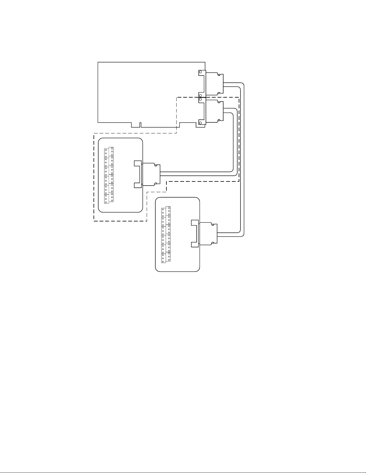
The STP-36 accessory provides basic screw terminal wiring to the I/O connector of a
KPCI-3130 Series board. All of the screw terminals are connected to the same-numbered pins of
a KPCI-3130 “Analog” or “Digital” I/O connector. Figure 1 shows how the accessory connects
to the KPCI-3130 or KPCI-3132.
PA-765 Rev. A / 12-00
2
Figure 1
Connecting STP-36 screw terminal accessory
Analog
Output
KPCI-3130 Series Board
General
Purpose
Digital I/O
STP-36
Accessory
Digital I/O Connector
KPCI-3130 Board Only
STP-36
Accessory
Analog Out Connector
CAB-1284CC
Series Cable
CAB-1284CC
Series Cable
Making two-wire and four-wire mode connections
The KPCI-3130 Series can be configured for two-wire (local sense) or four-wire (remote sense)
mode connections. The selected mode determines whether the KPCI-3130 Series eliminates
voltage drops due to the lead wire resistance between the STP-36 and the load terminals.
NOTE
The STP-36 Screw Terminal accessory interfaces the KPCI-3130 Series
analog connector to screw terminals that are numbered identically to
the pins.
Two-wire mode (local sense)
For two-wire mode connections, the KPCI-3130 Series boards sense at the channel output and
the channel ground at the terminals of the STP-36.
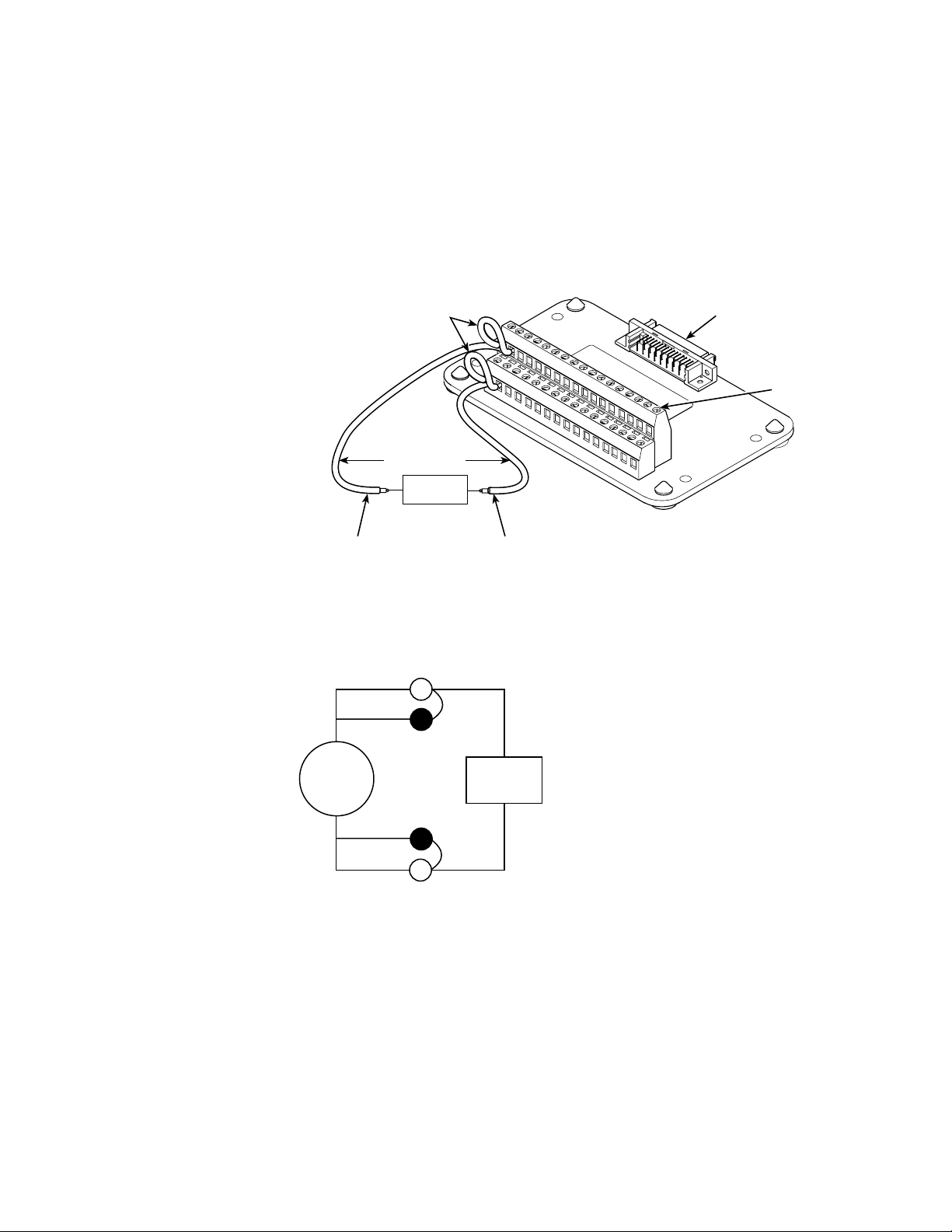
Two jumpers are required for connections in the two-wire mode. As shown in Figure 2, one
jumper is placed between Sense High and Channel Output. Another jumper is placed between
Sense Low and Channel Ground. Failure to install both of these jumpers for each channel
will result in an alarm flag for the specific channel and an overvoltage on the channel’s output if the channel is enabled. See Figure 3 for an example schematic.
3
For example, to configure CH0 for two-wire mode:
1. Install a jumper between pins 1 and 2 of the STP-36.
2. Install a jumper between pins 19 and 20 of the STP-36.
3. Connect the load between pins 1 and 19 or pins 2 and 20 of the STP-36.
NOTE
Terminate all unused channel sense lines (Sense HI to Output Sense LO to GND/return).
Figure 2
Two-wire mode connections
Jumpers
1
2
3
19
20
IEEE-1284C Connector
17
18
35
36
Screw
Terminals
Field Wires
LOAD
+-
Ch. output wire
Figure 3
Example of a two-wire mode connection
GND (return) wire
Out 0
+
KPCI-3130
Series
_
GND
Four-wire mode (remote sense)
For four-wire mode connections, the Sense High and Sense Low wires are connected between
the STP-36 and the load terminal, eliminating voltage drops due to lead (wire) resistance. The
desired output voltage appears at the load terminals. See Figures 4 and 5.
Note that for four-wire mode connections, there should not be any jumpers installed at the
STP-36 terminals.
 Loading...