

Page 1

User Manual
CMC251
1.3 GHz Frequency Counter
070-8527-03
Page 2

Copyright T ektronix, Inc. 1991. All rights reserved.
T ektronix products are covered by U.S. and foreign patents, issued and
pending. Information in this publication supercedes that in all previously
published material. Specifications and price change privileges reserved.
T ektronix, Inc., P.O. Box 1000, Wilsonville, OR 97070–1000
TEKTRONIX and TEK are registered trademarks of T ektronix, Inc.
Page 3

WARRANTY
Tektronix warrants that this product will be free from defects in materials and
workmanship for a period of one (1) year from the date of shipment. If any such product
proves defective during this warranty period, Tektronix, at its option, either will repair the
defective product without charge for parts and labor, or will provide a replacement in
exchange for the defective product.
In order to obtain service under this warranty, Customer must notify Tektronix of the defect
before the expiration of the warranty period and make suitable arrangements for the
performance of service. Customer shall be responsible for packaging and shipping the
defective product to the service center designated by Tektronix, with shipping charges
prepaid. Tektronix shall pay for the return of the product to Customer if the shipment is to
a location within the country in which the Tektronix service center is located. Customer
shall be responsible for paying all shipping charges, duties, taxes, and any other charges for
products returned to any other locations.
This warranty shall not apply to any defect, failure or damage caused by improper use or
improper or inadequate maintenance and care. Tektronix shall not be obligated to furnish
service under this warranty a) to repair damage resulting from attempts by personnel other
than Tektronix representatives to install, repair or service the product; b) to repair damage
resulting from improper use or connection to incompatible equipment; or c) to service a
product that has been modified or integrated with other products when the effect of such
modification or integration increases the time or difficulty of servicing the product.
THIS WARRANTY IS GIVEN BY TEKTRONIX WITH RESPECT TO THIS
PRODUCT IN LIEU OF ANY OTHER WARRANTIES, EXPRESSED OR
IMPLIED. TEKTRONIX AND ITS VENDORS DISCLAIM ANY IMPLIED
WARRANTIES OF MERCHANTABILITY OR FITNESS FOR A PARTICULAR
PURPOSE. TEKTRONIX’ RESPONSIBILITY TO REPAIR OR REPLACE
DEFECTIVE PRODUCTS IS THE SOLE AND EXCLUSIVE REMEDY
PROVIDED TO THE CUSTOMER FOR BREACH OF THIS WARRANTY.
TEKTRONIX AND ITS VENDORS WILL NOT BE LIABLE FOR ANY
INDIRECT, SPECIAL, INCIDENTAL, OR CONSEQUENTIAL DAMAGES
IRRESPECTIVE OF WHETHER TEKTRONIX OR THE VENDOR HAS
ADVANCE NOTICE OF THE POSSIBILITY OF SUCH DAMAGES.
Page 4

Page 5

Table of Contents
General Safety Summary iii. . . . . . . . . . . . . . . . . . . . . . . . . . . .
Getting Started 1. . . . . . . . . . . . . . . . . . . . . . . . . . . . . . . . . . . . .
Preparing the Frequency Counter for Use 2. . . . . . . . . . . . . . . . .
Front Panel 3. . . . . . . . . . . . . . . . . . . . . . . . . . . . . . . . . . . . . . . . .
Rear Panel 6. . . . . . . . . . . . . . . . . . . . . . . . . . . . . . . . . . . . . . . . .
Reference 9. . . . . . . . . . . . . . . . . . . . . . . . . . . . . . . . . . . . . . . . .
Making Frequency Measurements 9. . . . . . . . . . . . . . . . . . . . . . .
Frequencies Below 10 MHz 9. . . . . . . . . . . . . . . . . . . . . . . . .
Frequencies Below 100 MHz 10. . . . . . . . . . . . . . . . . . . . . . . .
Frequencies Between 80 MHz and 1.3 GHz 11. . . . . . . . . . . .
Making Period Measurements 11. . . . . . . . . . . . . . . . . . . . . . . . . .
Making Pulse-Width Measurements 13. . . . . . . . . . . . . . . . . . . . .
Remote Control of Pulse-Width Measurements 14. . . . . . . . .
Counting Events 15. . . . . . . . . . . . . . . . . . . . . . . . . . . . . . . . . . . . .
Remote Control of TOTAL Mode 16. . . . . . . . . . . . . . . . . . . .
Checking Instrument Operation 17. . . . . . . . . . . . . . . . . . . . . . . . .
Appendix A: Specifications 19. . . . . . . . . . . . . . . . . . . . . . . . . . .
Appendix B: Maintenance 25. . . . . . . . . . . . . . . . . . . . . . . . . . .
Cleaning 25. . . . . . . . . . . . . . . . . . . . . . . . . . . . . . . . . . . . . . . . . . .
Preparing for Shipment 25. . . . . . . . . . . . . . . . . . . . . . . . . . . . . . .
Troubleshooting 26. . . . . . . . . . . . . . . . . . . . . . . . . . . . . . . . . . . . .
No Display with Power On 26. . . . . . . . . . . . . . . . . . . . . . . . .
Appendix C: Replaceable Parts 27. . . . . . . . . . . . . . . . . . . . . . .
Standard Accessories 27. . . . . . . . . . . . . . . . . . . . . . . . . . . . . . . . .
Optional Accessories 27. . . . . . . . . . . . . . . . . . . . . . . . . . . . . . . . .
CMC251 User Manual
i
Page 6

T able of Contents
List of Tables
Table 1: A or B Channel Input 9. . . . . . . . . . . . . . . . . . . . . . .
Table 2: Selecting Features For Channel A
(1 Hz to 10 MHz) 10. . . . . . . . . . . . . . . . . . . . . . . . . . . . . . . .
Table 3: Selecting Features For Channel A
(10 MHz to 100 MHz) 10. . . . . . . . . . . . . . . . . . . . . . . . . . . .
Table 4: Gate Time Versus Resolution for Channel A 11. . . . .
Table 5: Gate Time Versus Resolution for Channel B 11. . . . .
Table 6: Period Measurements 12. . . . . . . . . . . . . . . . . . . . . . . .
Table 7: Resolution For Period Measurements 12. . . . . . . . . . .
Table 8: Pulse Width Measurements 13. . . . . . . . . . . . . . . . . . .
Table 9: Resolution for Pulse Measurements 14. . . . . . . . . . . .
Table 10: Warranted Characteristics 19. . . . . . . . . . . . . . . . . .
Table 11: Certifications and Compliances 23. . . . . . . . . . . . . .
Table 12: Typical Characteristics 23. . . . . . . . . . . . . . . . . . . . .
Table 13: Standard Accessories 27. . . . . . . . . . . . . . . . . . . . . . .
Table 14: Optional Accessories 27. . . . . . . . . . . . . . . . . . . . . . .
Table 15: Accessory Power Cords 28. . . . . . . . . . . . . . . . . . . . .
ii
CMC251 User Manual
Page 7

General Safety Summary
Review the following safety precautions to avoid injury and prevent
damage to this product or any products connected to it.
Injury Precautions
Use Proper Power Cord
T o avoid fire hazard, use only the power cord specified for this
product.
Avoid Electric Overload
T o avoid electric shock or fire hazard, do not apply a voltage to a
terminal that is outside the range specified for that terminal.
Ground the Product
This product is grounded through the grounding conductor of the
power cord. T o avoid electric shock, the grounding conductor must
be connected to earth ground. Before making connections to the
input or output terminals of the product, ensure that the product is
properly grounded.
Do Not Operate Without Covers
T o avoid electric shock or fire hazard, do not operate this product
with covers or panels removed.
Use Proper Fuse
T o avoid fire hazard, use only the fuse type and rating specified for
this product.
CMC251 User Manual
iii
Page 8

General Safety Summary
Do Not Operate in Wet/Damp Conditions
T o avoid electric shock, do not operate this product in wet or damp
conditions.
Do Not Operate in Explosive Atmosphere
T o avoid injury or fire hazard, do not operate this product in an
explosive atmosphere.
Product Damage Precautions
Use Proper V oltage Setting
Before applying power, ensure that the line selector is in the proper
position for the power source being used.
Provide Proper Ventilation
T o prevent product overheating, provide proper ventilation.
Do Not Operate With Suspected Failures
If you suspect there is damage to this product, have it inspected by
qualified service personnel.
Safety Terms and Symbols
Terms in This Manual
These terms may appear in this manual:
WARNING. Warning statements identify conditions or practices that
could result in injury or loss of life.
iv
CMC251 User Manual
Page 9

General Safety Summary
CAUTION. Caution statements identify conditions or practices that
could result in damage to this product or other property.
Terms on the Product
These terms may appear on the product:
DANGER indicates an injury hazard immediately accessible as you
read the marking.
WARNING indicates an injury hazard not immediately accessible as
you read the marking.
CAUTION indicates a hazard to property including the product.
Symbols on the Product
The following symbols may appear on the product:
DANGER
High Voltage
Protective Ground
(Earth) T erminal
Certifications and Compliances
CSA Certified Power Cords
CSA Certification includes the products and power cords appropriate
for use in the North America power network. All other power cords
supplied are approved for the country of use.
CMC251 User Manual
ATTENTION
Refer to
Manual
Double
Insulated
v
Page 10

General Safety Summary
vi
CMC251 User Manual
Page 11

Getting Started
The Tektronix CMC251 Frequency Counter can make the following
frequency-related measurements:
H Frequency measurements up to 1.3 GHz
H Period measurements at rates up to 25 MHz
H Period averaging of up to 1000 events
H Pulse measurements up to 0.25 s
H Event counting
The 10 MHz internal time base (using a highly stabilized crystal
oscillator) provides a single-shot resolution of 100 ns. Measurement
results are displayed using an eight digit display, automatically
placing the decimal appropriately.
The CMC251 Frequency Counter has a locking, multiposition handle
that folds under the instrument. The instrument is delivered with a
115 V power cord, an installed fuse for 115 V operation, and this
manual.
CMC251 User Manual
1
Page 12
Getting Started
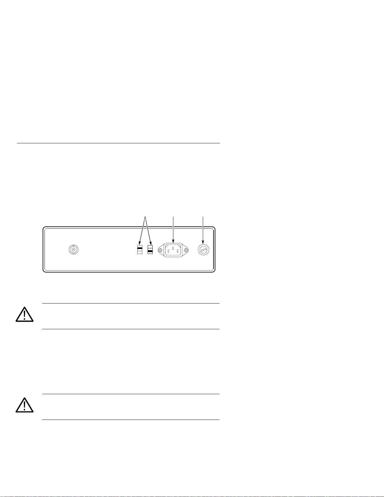
Preparing the Frequency Counter for Use
Check the following items prior to operating the frequency counter
for the first time (see Figure 1 for locations of items 1 through 3):
1 23
Figure 1: Line Voltage Selectors, Power Input, and Fuse Locations
CAUTION. To prevent damage to the instrument, set the line voltage
selectors to the proper voltage setting and install the correct line
voltage fuse before operating the equipment.
1. Set the line voltage selectors to the input line voltage. These
selectors connect internal wiring for various line voltages. This
product is intended to operate from a power source that does not
supply more than 250 V
between either supply conductor and ground. For line voltage
ranges, refer to Appendix A: Specifications on page 19.
WARNING. To prevent electrical shock, unplug the power cord and
disconnect the signal input cable from any signal source before
checking or replacing the fuse.
2. Check that the correct line fuse is installed. The line fuse
provides protection if the equipment malfunctions or an overload
occurs. Refer to Appendix C: Replaceable Parts on page 27 for
fuse part numbers.
2
between the supply conductors or
RMS
CMC251 User Manual
Page 13

WARNING. To prevent electrical shock, connect the power cord to a
properly grounded power source. The outside (ground) of this
connector is connected through the equipment to the power source
ground. Do not remove the ground lug from the power cord for any
reason.
3. Connect the input power cord. Use only the power cords specified
for this equipment. Refer to Appendix C: Replaceable Parts on
page 27 for power cord part numbers.
Front Panel
Figure 2 shows the front panel controls, connectors, and indicators
with brief descriptions of the items following the figure.
12345
Getting Started
17
Figure 2: Front Panel Controls, Connectors, and Indicators
CAUTION. To avoid the risk of fire or possible damage to the
CMC251, be sure that the equipment generating the signal is
properly grounded before you make any connections to the inputs.
1. CHANNEL B INPUT Button. Use this input connector to
CMC251 User Manual
16 15 14 13 12 11 10 9 8 7 6
measure signals with a repetition rate from 80 MHz to 1.3 GHz.
3
Page 14

Getting Started
2. OVERRANGE Indicator . Lights when frequencies above the
3. Display . The display area provides measurement information on
specified limits are applied to either channel.
the digital display. Single LEDs indicate the units and conditions
of the display.
4. kHz
s Indicator Lights when a frequency mode is selected and
the PRESCALE button is in its out position, indicating that the
reading is in kilohertz. When the period or pulse mode is
selected, the LED lights to indicate the reading is in
microseconds.
5. MHz Indicator. Lights when a frequency mode is selected and the
PRESCALE button is pressed in, indicating that the reading is in
megahertz.
6. GATE Indicator. Lights while the frequency counter is making a
measurement. The LED extinguishes when updating the display.
7. Gate Resolution Indicators. These LEDs light to indicate the
present gate resolution settings (X1, X10, X100, or X1000).
8. POWER Switch. Powers the instrument on and off.
9. GATE Button. Determines the display’s degree of resolution by
setting the gate time (the amount of time the counter uses to
derive its displayed value). The selected resolution is indicated by
the lighted LED. Each press of the button changes the degree of
resolution to the next level.
10.FUNC Button. Determines the operating mode of the CMC251
Frequency Counter.
11. HOLD Button. Stops or locks the display when pressed in.
T oggling the button to its out position allows the measurement to
continue. When using the TOTAL mode, pressing the HOLD
button freezes the display but event counting continues.
12.RESET Button. Sets the display to all zeros; new measurements
will be displayed after the button is released.
4
CMC251 User Manual
Page 15

Getting Started
13.PRESCALE Button. Divides the frequency of the signal applied
to CHANNEL A INPUT by a factor of ten and sets the measurement units indicator to either MHz or kHz
s. When pushed in,
frequencies up to 100 MHz or periods up to 0.04 s can be
measured. In the out position, frequencies up to 10 MHz or
periods up to 0.4 s can be measured.
14.Mode Indicators. These LEDs light to indicate the present mode
settings. One of the following modes is indicated:
H FREQ A—The Frequency A mode measures the repetition
rate of the signal applied to the CHANNEL A INPUT. In this
mode, measurements from 1 Hz to 100 MHz can be made.
H FREQ B—The Frequency B mode measures the repetition
rate of the signal applied to the CHANNEL B INPUT. In this
mode, measurements from 80 MHz to 1.3 GHz can be made.
H PERIOD A—The Period A mode measures the time it takes
for one cycle of the signal applied to CHANNEL A INPUT to
be completed.
H PULSE A—The Pulse A mode measures the width of the
positive pulses of the signal applied to CHANNEL A INPUT.
The Pulse mode can also measure the negative pulse of the
input signal when using the external control input connector
located on the rear panel. See Making Pulse-Width Measure-
ments on page 13 for a description of its use.
H TOTAL—The Totalize mode counts signal events applied to
CHANNEL A INPUT, incrementing one count for each
event. The display is updated continuously unless the HOLD
button is pressed. The count resumes when the HOLD button
is released. The T otalize mode can also be controlled
remotely with the use of the external control input connector
located on the rear panel.
H CHECK—The Check mode uses the internal time base as a
signal source to make a general check of the operating
system. The display will indicate a frequency of 10 MHz.
CMC251 User Manual
5
Page 16

Getting Started
15.LOW PASS FILTER Button. Attenuates signals applied to
16.INPUT VOLTAGE Button. Allows you to select between two
CAUTION. To avoid the risk of fire or possible damage to the
CMC251, be sure that the equipment generating the signal is
properly grounded before you make any connections to the inputs.
17.CHANNEL A INPUT. Use this connector to measure signals with
CHANNEL A INPUT that are above 100 kHz, preventing
high-frequency interference. Select this mode to measure signals
below 100 kHz.
levels of input signals for the CHANNEL A INPUT. When
pushed in, the maximum allowable peak-to-peak input level is
from 3 V to 42 V (30 Vrms). When in the out position, the
maximum allowable peak-to-peak input level is from 50 mV to
5V.
a repetition rate from 1 Hz to 100 MHz.
Rear Panel
In addition to the line voltage selectors, power input, and fuse, there
is a BNC connector for an external control input located on the rear
panel
CAUTION. To avoid the risk of fire or possible damage to the
CMC251, be sure the input equipment is properly grounded before
making any connections. The external input connector is grounded to
the power source ground.
The external control input (see Figure 3, item 1) provides remote
control of two instrument functions: TOTAL and PULSE modes.
6
CMC251 User Manual
Page 17

Getting Started
1
Figure 3: Rear Panel Signal Connections
In T otal mode, the TTL logic levels start (TTL high) and stop (TTL
low) the display updates. This performs the same function as the
HOLD button.
In Pulse mode, the TTL logic levels select either negative (TTL low)
or positive (TTL high) pulse width measurement.
CMC251 User Manual
7
Page 18

Getting Started
8
CMC251 User Manual
Page 19

Reference
Table 1: A or
This section describes typical setups of the CMC251 Frequency
Counter for each of its measurement modes.
Making Frequency Measurements
Measuring frquencies with the CMC251 Frequency Counter is
simple, although there are some items you need to consider before
applying the signal to the inputs of the frequency counter.
1. Estimate the frequency of the signal source and determine the
voltage level.
This enables you to use the appropriate input channel of the
frequency counter. A good practice is to display the signal on an
oscilloscope and obtain the peak voltage level. Refer to T able 1
and pick the appropriate input channel.
B Channel Input
Estimated Frequency
1 Hz to 100 MHz Less than 42 V peak CHANNEL A INPUT
80 MHz to 1.3 GHz Less than 1 V
2. Prepare to make a measurement, using the steps under one these
sections: Frequencies Below 10 MHz, Fr equencies Below
100 MHz, or Frequencies Between 80 MHz and 1.3 GHz.
Frequencies Below 10 MHz
1. Press the FUNC button until FREQ A is indicated with a lighted
LED.
2. Refer to T able 2 and set the frequency counter front-panel buttons
to obtain the best measurement for frequencies below 10 MHz.
CMC251 User Manual
Input Voltage Proper Input Channel
RMS
CHANNEL B INPUT
9
Page 20

Reference
Table 2
electi
Table 3
electi
100
: S
ng Features For Channel A (1 Hz to 10 MHz)
50 mV to 5 V 3 V to 42 V
INPUT VOLTAGE LO (button out) HI (button in)
LOW PASS FILTER ON (button in) ON (button in)
PRESCALE Button Out Button Out
3. Connect the signal to the CHANNEL A INPUT connector.
4. Press the GATE button to select the desired display resolution.
See T ables 4 and 5 for resolution-versus-gate settings.
Frequencies Below 100 MHz
1. Press the FUNC button until FREQ A is indicated with a lighted
LED.
2. Refer to T able 3 and set the frequency counter front-panel buttons
to obtain the best measurement for frequencies between 10 MHz
and 100 MHz.
: S
ng Features For Channel A (10 MHz to
MHz)
50 mV to 5 V 3 V to 42 V
INPUT VOLTAGE LO (button out) HI (button in)
10
LOW PASS FILTER OFF (button out) OFF (button out)
PRESCALE Button In Button In
3. Connect the signal to the CHANNEL A INPUT input connector.
4. Press the GATE button to select the desired display resolution.
See T ables 4 and 5 for resolution versus gate settings.
CMC251 User Manual
Page 21

Reference
Table 4: Gate Time Ver
A
Table 5: Gate Time Ver
Frequencies Between 80 MHz and 1.3 GHz
1. Press the FUNC button until FREQ B is indicated by a lighted
LED.
2. After determining that the signal voltage level is 1 V rms or less,
connect the signal to the CHANNEL B INPUT connector.
3. Press the GATE button to select the desired display resolution.
Refer to T ables 4 and 5 for resolution-versus-gate settings.
sus Resolution for Channel
GA TE Setting Gate Time Resolution
PRESCALE Off PRESCALE On
X1 0.01 seconds 100 Hz 1 kHz
X10 0.1 seconds 10 Hz 100 Hz
X100 1 second 1 Hz 10 Hz
X1000 10 seconds 0.1 Hz 1 Hz
Making Period Measurements
CMC251 User Manual
sus Resolution for Channel B
GA TE Setting
X1 0.016 seconds 10 kHz
X10 0.16 seconds 1 kHz
X100 1.6 seconds 100 Hz
X1000 16 seconds 10 Hz
A Period measurement is the time in seconds for a signal to complete
one entire cycle. This measurement is taken by averaging the signal
events for a certain number of internal clock pulses. Therefore, the
gate setting determines the resolution (or accuracy) of the reading.
Gate Time Resolution
11
Page 22

Reference
Table 6
eri
Table 7: Resoluti
eri
T o make a period measurement, perform the following steps:
1. Estimate the signal source frequency and determine the voltage
level. A good practice is to display the signal on an oscilloscope
and obtain the peak voltage level.
2. Refer to T able 6 and set the frequency counter front-panel buttons
to obtain the best period measurements.
: P
od Measurements
>40 ns (<25 MHz) >400 ns (<2.5 MHz)
50 mV to 5 V 3 V to 42 V 50 mV to 5 V 3 V to 42 V
INPUT
VOLTAGELO(button out)
HI
(button in)
LO
(button out)
HI
(button in)
PRESCALE
Button In Button In Button Out Button Out
3. Press the FUNC button until PERIOD A is indicated with a
lighted LED.
4. Connect the signal to the CHANNEL A INPUT connector.
5. Press the GATE button to select the desired display resolution.
Refer to T able 7 for the available resolutions.
on For P
GA TE Setting
od Measurements
Number of Events averaged
PRESCALE In PRESCALE Out
X1 10 cycles 1 cycle
X10 100 cycles 10 cycles
X100 1000 cycles 100 cycles
X1000 10000 cycles 1000 cycles
12
CMC251 User Manual
Page 23

Making Pulse-Width Measurements
Table 8
A pulse-width measurement is the time in seconds from one edge of
the signal to the next edge. This measurement is accomplished by
averaging the signal events for a certain number of internal clock
pulses determined by the gate setting. Therefore, the gate setting
determines the resolution (or accuracy) of the reading.
The CMC251 Frequency Counter normally measures the positive
pulse width, but it can measure the negative pulse width using the
external input connector on the rear panel. This method is discussed
in Remote Control of Pulse-Width Measurements on page 14.
1. Determine the signal voltage level. A good practice is to display
the signal on an oscilloscope and obtain the peak voltage level.
2. Refer to T able 8 and set the frequency counter front-panel buttons
to obtain the best pulse measurements.
: Pulse Width Measurements
50 mV to 5 V 3 V to 42 V
INPUT VOLTAGE LO (button out) HI (button in)
Reference
LOW PASS FILTER OFF (button out) OFF (button out)
PRESCALE No Effect No Effect
3. Press the FUNC button until PULSE A is indicated by a lighted
LED.
4. Connect the signal to the CHANNEL A INPUT connector.
5. Press the GATE button to select the desired display resolution.
See T able 9 for the available resolutions.
CMC251 User Manual
13
Page 24

Reference
Table 9: Resoluti
on for Pulse Measurements
GA TE Setting
X1 1 cycle
X10 10 cycles
X100 100 cycles
X1000 1000 cycles
Number of Events Averaged
Remote Control of Pulse-Width Measurements
The frequency counter normally measures the positive pulse width of
the applied signal. The negative pulse width can be measured with
the use of the external input connector on the rear panel. Refer to
Figure 4 for a setup diagram.
To External Input
connector (on rear panel)
Signal source
CMC251
TTL Signal source
14
CHANNEL A
INPUT
Figure 4: Setup for Remote Control of Pulse-Width Measurements
1. Perform steps 1 through 5 of Making Pulse-Width Measurements
on page 13.
CMC251 User Manual
Page 25

CAUTION. To avoid damage to the CMC251 Frequency Counter,
ensure that the maximum voltage into the rear panel external input is
no more than +5 V (TTL logic level).
2. Connect a TTL logic low level (0 volts) to the external input
connector.
NOTE. Shorting the external input connector to ground accomplishes
the same task as applying a TTL logic low.
3. The display reading indicates the negative pulse width. Changing
the TTL logic level to high (+5 V) enables the frequency counter
to measure the positive pulse width.
Counting Events
The CMC251 Frequency Counter can be used to count signal events.
This feature can be controlled remotely with the use of TTL logic
levels applied to the external input connector located on the rear
panel. Refer to Remote Control of TOTAL Mode on page 16 for a
description of its use.
Reference
1. Determine the signal voltage level. A good practice is to display
the signal on an oscilloscope and obtain the peak voltage level.
2. Set the Channel A INPUT VOLTAGE switch as necessary,
determined by the voltage reading obtained in Step 1.
3. Press the FUNC button until TOTAL is indicated by a lighted
LED.
4. Connect the signal to the CHANNEL A INPUT connector.
The frequency counter will start counting events immediately and
continue until the signal is disconnected.
Pressing the HOLD button freezes the display , but the count
continues internally. The display will update when the HOLD button
is toggled out and the count resumes.
CMC251 User Manual
15
Page 26

Reference
Pressing the RESET button clears the display and resets the count
back to zero. The count resumes when the RESET button is
released.
Remote Control of TOTAL Mode
Refer to Figure 5 for the setup diagram for remotely controlling the
TOTAL mode.
1. Perform Steps 1 through 4 of Counting Events on page 15.
2. Connect a signal source that can apply TTL logic levels of low
and high (0 V and +5 V) to the external input connector.
CAUTION. To avoid damage to the CMC251 Frequency Counter,
ensure that the maximum voltage into the rear panel input is no more
than +5 V (TTL logic level).
16
To External Input
connector (on rear panel)
Signal source
CMC251
CHANNEL A
INPUT
TTL Signal source
Figure 5: Setup for Remote Control of TOTAL modes
CMC251 User Manual
Page 27

3. Control the TOTAL mode by applying a TTL logic signal to the
external input connector as folows:
H Apply a low level (0 volts) to stop the count (same as the HOLD
button)
H Apply a TTL logic high level (+5 V) to resume the count (same
as releasing the HOLD button)
Checking Instrument Operation
At any time, you can verify the accuracy of the CMC251 Frequency
Counter by using the CHECK function. Press the FUNC button until
CHECK is indicated by the lighted LED. The readout will display
10.000 MHz.
Reference
CMC251 User Manual
17
Page 28

Reference
18
CMC251 User Manual
Page 29

Appendix A: Specifications
T able 10 and 11 list the characteristics of theCMC251 Frequency
Counter that are guaranteed by the warranty.
Table 10: Warranted Characteristics
Characteristic
Measurement
Channel A Input
Bandwidth 1 Hz to 100 MHz, AC coupled
Sensitivity (Sine wave
terminated into 1 M
20 mV
RMS
50 mV
RMS
Impedance
Attenuation 3 V to 42 V (HI)
Maximum Input Voltage 42 V peak
Filter –3 dB at 100 kHz
W)
1 Hz to 30 MHz
30 MHz to 100 MHz
1 MW paralleled by 40 pF
50 mV to 5 V (LO)
CMC251 User Manual
19
Page 30

Appendix A: Specifications
Table 10: Warranted Characteristics (Cont.)
Characteristic Measurement
Channel B Input
Bandwidth 80 MHz to 1.3 GHz, AC coupled
Sensitivity (Sine wave
terminated into 50
W)
5 mV
RMS
15 mV
RMS
35 mV
RMS
Impedance
Maximum Input Voltage 1 V
80 MHz to 600 MHz
600 MHz to 900 MHz
900 MHz to 1.3 GHz
50 W
rms
Internal Time Base
Crystal Frequency 10 MHz (TCXO)
Setability ±0.1 ppm (±1 Hz)
Temperature Stabillity
<0.0001% (1 ppm from 0_C to 40_C)
Line Voltage Stability <±0.4 ppm with 10% line voltage variation
Aging Rate <±1 ppm/yr
Display
Display Update Time
Frequency Mode
Channel A: Selected GATE time plus 200 ms interval
Channel B: Selected GATE time plus 640 ms interval
Period Mode
Selected cycles averaging plus 200 ms interval
Pulse Mode
Totalize Mode
20
Selected cycles averaging plus 200 ms interval
Continuous
CMC251 User Manual
Page 31

Appendix A: Specifications
Table 10: Warranted Characteristics (Cont.)
Characteristic Measurement
Frequency Mode
Measurement specifications for frequency mode are applicable for a sine wave applied to
the inputs.
Channel A Range Prescale In Prescale Out
10ĂMHz to 100ĂMHz 1ĂHz to 10ĂMHz
Channel B Range 80 MHz to 1.3 GHz
Accuracy ±(1 count + time base error)
Channel A Resolution Prescale In Prescale Out
1ĂHz to 1ĂkHz 0.1ĂHz to 100ĂHz
Channel B Resolution 10 Hz to 10 kHz
Period Mode
Range Prescale In Prescale Out
0.04Ăs to 1.0Ăs 0.4Ăs to 1.0Ăs
Frequency Range
(Sine wave)
Accuracy ±(1 count + time base error + trigger error)
Resolution Prescale In Prescale Out
Prescale In Prescale Out
1ĂHz toĂ25 MHz 1ĂHz to 2.5ĂMHz
10Ăps to 10Ăns 100Ăps toĂ100 ns
Pulse Mode
Range
Frequency Range 1 Hz to 2 MHz
Accuracy ±(1 count + time-base error + trigger error + 100 ns)
Resolution 100 ps to 100 ns, switchable in four decade steps
0.25 s to 500 ms
CMC251 User Manual
21
Page 32

Appendix A: Specifications
Table 10: Warranted Characteristics (Cont.)
Characteristic Measurement
Totalize Mode
Range 0 to 99,999,999 counts plus overrange
Repetition Rate
(Sine wave)
1 Hz to 10 MHz
Power
Line Voltage Range Selectable ranges at 50 Hz to 60 Hz
90 VAC to 110 VAC
108 VAC to 132 VAC
198 VAC to 242 VAC
216 VAC to 250 VAC
Environmental
Operating Temperature
Storage Temperature
+10_C to +40_C, 75% relative humidity
–10_C to +60_C, 80% relative humidity
22
CMC251 User Manual
Page 33

Table 11: Certifications and Compliances
Appendix A: Specifications
EC Declaration of
Conformity – EMC
EC Declaration of
Conformity – Low
Voltage
Meets intent of Directive 89/336/EEC for Electromagnetic
Compatibility. Compliance was demonstrated to the following
specifications as listed in the Official Journal of the European
Communities:
EN 55011 Class A Radiated and Conducted Emissions
EN 50081-1 Emissions:
EN 60555-2 AC Power Line Harmonic Emissions
EN 50082-1 Immunity:
IEC 801-2 Electrostatic Discharge Immunity
IEC 801-3 RF Electromagnetic Field Immunity
IEC 801-4 Electrical Fast Transient/Burst Immunity
IEC 801-5 Power Line Surge Immunity
Compliance was demonstrated to the following specification as
listed in the Official Journal of the European Communities:
Low Voltage Directive 73/23/EEC, amended by 93/68/EEC.
HD401 S1 Safety Requirements for Electronic
T able 12 lists the nonwarranted specifications of the CMC251
Frequency Counter.
Table 12: Typical Characteristics
Measuring Aparatus.
Characteristic
Dimensions
(H x W x D)
Power Consumption 22 VA, 12 W maximum
Measurement
67 mm X 262mm X 230 mm
(2.6 in X 10.3 in X 9.0 in)
CMC251 User Manual
23
Page 34

Appendix A: Specifications
24
CMC251 User Manual
Page 35

Appendix B: Maintenance
This appendix provides information for the basic maintenance of the
CMC251 Frequency Counter.
Cleaning
T o clean the frequency counter, use a soft cloth dampened in a
solution of mild detergent and water. Do not spray cleaner directly
onto the instrument, since it may leak into the cabinet and cause
damage.
Do not use chemicals containing benzine, benzene, toluene, xylene,
acetone, or similar solvents.
Do not use abrasive cleaners on any portion of the frequency counter.
Preparing for Shipment
If the original packaging is unfit for use or not available, use the
following packaging guidelines:
1. Use a corrugated cardboard shipping carton having inside
dimensions at least three inches greater than the instrument
dimensions.
2. Put the instrument into a plastic bag or wrap to protect it from
dampness and loose packing material.
3. Place the instrument into the box and firmly stabilize it with
packing material.
4. Seal the carton with shipping tape.
CMC251 User Manual
25
Page 36

Appendix B: Maintenance
Troubleshooting
Electronic maintenance on the CMC251 Frequency Counter must be
performed by a trained technician. However, an operator can perform
some basic and routine maintenance. The CMC251 Frequency
Counter will give some indications of problems to aid the operator.
WARNING. To prevent electrical shock, unplug the power cord and
disconnect the signal input cable from any signal source before
checking or replacing the fuse.
No Display with Power On
If the digital display is not lighted, but the POWER button is pushed
in and the CMC251 Frequency Counter power cord is plugged into
an outlet, do the following steps:
1. Check the line fuse. If the fuse is open, replace it.
26
2. If the line fuse is good, check the power outlet for proper voltage.
If the outlet voltage is incorrect, call service personnel.
WARNING. To prevent electric shock, disconnect the power cord from
the power source and the CMC251 Frequency Counter before
checking continuity.
3. If outlet voltage is correct, check power cord continuity. If the
power cord fails the continuity check, replace the power cord.
CMC251 User Manual
Page 37

Appendix C: Replaceable Parts
Replaceable parts may be ordered directly from your authorized
T ektronix dealer.
Standard Accessories
The following items are shipped with the CMC251 Frequency
Counter:
Table 13: Standard Accessories
Accessory
Fuse, 3AG, 0.3 A, 250 V, SB
(90 – 132 V operation)
User Manual 070–8527–XX
115 V Power Cord Refer to Table 15
Optional Accessories
The following items are available as optional accessories:
Table 14: Optional Accessories
Accessory
Fuse, 3AG, .0125 A, 250 V, SB
(198 – 250 V operation)
230 V Power Cords Refer to Table 15
36-inch, 50 BNC cable
66-inch, 50 coaxial cable signal
adapter
Tektronix Part Number
159–0029–00
Tektronix Part Number
159–0313–00
012–1341–XX
103–0275–XX
CMC251 User Manual
27
Page 38

Appendix C: Replaceable Parts
The following power cords are available.
Table 15: Accessory Power Cords
Plug Configuration
Normal Usage
North America
115 V
Tektronix Part
Number
161-0104-00
Europe
230 V
United Kingdom
230 V
Australia
230 V
North America
230 V
Switzerland
230 V
161-0104-06
161-0104-07
161-0104-05
161-0104-08
161-0167-00
28
CMC251 User Manual
 Loading...