

Page 1

xx
Tektronix Logic Analyzer
ZZZ
Online Help
PrintedHelpDocument
*P076011305*
076-0113-05
Page 2

Page 3

Tektronix Logic Analyzer
Online Help
ZZZ
PrintedHelpDocument
www.tektronix.com
076-0113-05
Page 4

Copyright © Tektronix. All rights reserved. Licensed software products are owned by Tektronix or its
subsidiaries or suppliers, and are protected by national copyright laws and international treaty provisions.
Tektronix products are covered by U.S. a nd foreign patents, issued and pending. Information in this
publication supersedes that in all previously published material. Specifications and p rice change privileges
reserved.
TEKTRONIX and TEK are registered trademarks of Tektronix, Inc.
D-Max, MagniVu, iView, iVerify, iCapture, iLink, PowerFlex, and TekLink are trademarks of Tektronix,
Inc.
076-0113-05
077-0032-05
May 24, 2011
Contacting Tektronix
Tektronix, Inc.
14150 S
P.O . Box 500
Beaverton, OR 97077
USA
WKarlBraunDrive
For product information, sales, service, and technical support:
rth America, call 1-800-833-9200.
In No
Worldwide, visit www.tektronix.com to find contacts in your area.
Page 5

Warranty
Tektronix warrants that this product will be free from defects in materials and workmanship for a period of
one (1) year from the date of shipment. If any such product proves defective during this warranty period,
Tektronix, at its option, either will repair the defective product without charge for parts and labor, or will
provide a rep
by Tektronix for warranty work may be new or reconditioned to like new performance. All replaced parts,
modules and products become the property of Tektronix.
In order to obtain service under this warranty, Customer must notify Tektronix of the defect before the
expiration of the warranty period and make suitable arrangements for the performance of service. Customer
shall be responsible for packaging and shipping the defective product to the service center designated by
Tektronix, with shipping charges prepaid. Tektronix shall pay for the return of the product to Customer if
the shipment is to a location within the country in which the Tektronix service center is located. Customer
shall be r
to any other locations.
lacement in exchange for the defective product. Parts, modules and replacement products used
esponsible for paying all shipping charges, duties, taxes, and any other charges for products returned
This war
inadequate maintenance and care. Tektronix shall not be obligated to furnish service under this warranty a) to
repair damage resulting from attempts by personnel other than Tektronix representatives to install, repair or
service the product; b) to repair damage resulting from improper use or connection to incompatible equipment;
c) to repair any damage or malfunction caused by the use of non-Tektronix supplies; or d) to service a product
that has been modi fied or integrated with other products when the effect of such modification or integration
incr
THIS WARRANTY IS GIVEN BY TEKTRONIX WITH RESPECT TO THE PRODUCT IN LIEU OF ANY
OTHE
IMPLIED WARRANTIES OF MERCHANTABILITY OR FITNESS FOR A PARTICULAR PURPOSE.
TEKTRONIX' RESPONSIBILITY TO REPAIR OR REPLACE DEFECTIVE PRODUCTS IS THE SOLE
AND EXCLUSIVE REMEDY PROVIDED TO THE CUSTOMER FOR BREACH OF THIS WARRANTY.
TEKTRONIX AND ITS VENDORS WILL NOT BE LIABLE FOR ANY INDIRECT, SPECIAL,
INCIDENTAL, OR CONSEQUENTIAL DAMAGES IRRESPECTIVE OF WHETHER TEKTRONIX OR
HE VENDOR HAS ADVANCE NOTICE OF THE POSSIBILITY OF SUCH DAMAGES.
T
[W2 – 15AUG04]
ranty shall not apply to any defect, failure or damage caused by improper use or improper or
eases the time or difficulty of servicing the product.
R WARRANTIES, EXPRESS OR IMPLIED. TEKTRONIX AND ITS VENDORS DISCLAIM ANY
Page 6

Warranty
Tektronix warrants that the media on which this software product is furnished and the encoding of the programs
on the media will be free from defects in materials and workmanship for a period of three (3) months from the
date of shipment. If any such medium or encoding proves defective during the warranty period, Tektronix will
provide a rep
product is furnished, this software product is provided “as is” without warranty of any kind, either express or
implied. Tektronix does not warrant that the functions contained in this software product will meet Customer's
requirements or that the operation of the programs will be uninterrupted or error-free.
In order to obtain service under this warranty, Customer must notify Tektronix of the defect before the
expiration of the warranty period. If Tektronix is unable to provide a replacement that is free from defects in
materials and workmanship within a reasonable time thereafter, Customer may terminate the license for this
software product and return this software product and any associated materials for credit or refund.
THIS WARRANTY IS GIVEN BY TEKTRONIX WITH RESPECT TO THE PRODUCT IN LIEU OF ANY
OTHER WARRANTIES, EXPRESS OR IMPLIED. TEKTRONIX AND ITS VENDORS DISCLAIM ANY
IMPLIED
TEKTRONIX' RESPONSIBILITY TO REPLACE DEFECTIVE MEDIA OR REFUND CUSTOMER'S
PAYMENT IS THE SOLE AND EXCLUSIVE REMEDY PROVIDED TO THE CUSTOMER FOR
BREACH OF THIS WARRANTY. TEKTRONIX AND ITS VENDORS WILL NOT BE LIABLE FOR
ANY INDIRECT, SPECIAL, INCIDENTAL, OR CONSEQUENTIAL DAMAGES IRRESPECTIVE OF
WHETHER TEKTRONIX OR THE VENDOR HAS ADVANCE NOTICE OF THE POSSIBILITY OF
SUCH
lacement in exchange for the defective m edium. Except as to the media on which this software
WARRANTIES OF MERCHANTABILITY OR FITNESS FOR A PARTICULAR PURPOSE.
DAMAGES.
[W9b–15AUG04]
Page 7

Table of Contents
Welcome
Technical Support ............................... ................................ ................................ ... 1
About Tektronix Logic Analyzers ................... ................................ ............................. 1
Customer Feedback ................................................................................................ 2
Getting Started
Overview of Connection Choices.......................... ................................ ....................... 3
Configuring your TLA7000 without a TL708EX ............................................................... 4
Connect to a Networked Instrument.............................................................................. 5
Network Search..................................................................................................... 7
Network Properties ................................................................................................. 8
Options of Powering On and Off ...................... ................................ ........................... 9
Examine the Waveform ........................................................................................... 10
Viewing Other Types of Waveforms .......................... ................................ .................. 11
Viewing a Magnitude Waveform Sample....................................................................... 12
Examine the Listing Data..................... ................................ .................................. .. 13
Searching Selected Data .......................................................................................... 14
Table of Contents
System Setup
LA Setup Window
LA Setup Window ............................................................................................ 15
Sampling..... ................................ .................................. ................................ 16
Synchronous Sampling: Define Single Clock ............................................................. 17
Synchronous Sampling: Define Compound Clock........................................................ 18
Deskew Panel ....................... .................................. ................................ ........ 19
Group Deskew ................................................................................................ 19
Signal Mapping Area......................................................................................... 20
Group Management Area .................................................................................... 24
Signal Sampling Screen: Setting Thresholds ... . .... ..... ..... .... . .... . .... ... . . .... . .... ..... ..... .... . . 25
Signal Sampling Screen: Adjusting Setup and Hold V
Acquisition Options . ..... .... . .... . .... . .... . .... ..... ..... .... . .... . .... . .... . .... ..... ..... .... . .... . .... . . 27
Sample Storage................................................................................................ 29
Merged Module Synchronous Sampling ................................................................... 29
Highlight Signal Names Dialog Box ......... ................................ .............................. 30
iCapture Analog Feeds ............................... ................................ ........................ 31
Filters
Filter Definitions Dialog Box........................................... ................................ 34
Define Filter Dialog Box.... ..... ..... ..... ..... ..... ..... ..... ..... ..... ..... ..... ..... ..... ..... ... . . . 34
alues ....................... ...................... 26
TLA Online Help i
Page 8

Table of Contents
Signal Import and Export
Logic Protocol Analyzer Setup Window
Logic Protocol Analyzer Setup Window ................................................................... 46
Status Area .............. .................................. ................................ .................... 46
Left Side Control Area ......... ................................ ................................ .............. 47
Channel-Lane Assignment Area ............................................................................ 49
Multimodule Logic Protocol Analyzer Configurations................................................... 49
Probe Calibration Area. .................................. ................................ .................... 50
Calibrate the Logic Protocol Analyzer Probes............................... .............................. 52
External Oscilloscope Setup Window
Setting Up External Oscilloscope Communication . . .... ..... .... . .... . .... ..... ... . . .... . .... ..... .... . . 53
iView Setup Window..................... ................................ .................................. .. 53
Troubleshooting External Oscillosco
Signal Routing from the Logic Analyzer................................................................... 55
Signal Routing to the Oscilloscope . .... . .... ..... ... . . .... . .... . .... ..... ... . . .... . .... . .... . .... ..... ... . . 56
System Inter-Probing......................................................................................... 57
Load Filter Dialog Box.... ................................ .................................. ............ 36
Load Filter Browser Dialog Box ..... ................................ .................................. 37
Applying Filters .. . .... . .... ..... ... . . .... . .... ..... .... . .... . .... ..... ..... .... . .... . .... ..... ..... .... . . 37
Color Options Dialog Box .............................................................................. 38
Signal Import and Export Formats..................................................................... 38
Signal Setup Import B
Signal Setup Export Dialog Box ....................................................................... 40
Signal Setup Import Dialog Box ....................................................................... 41
Sample Signal Setup File ............................................................................... 41
Comment Lines ................ ................................ .................................. ........ 43
Control Lines ............................................................................................. 43
Information Lines................ .................................. ................................ ...... 45
ehavior .......................................................................... 38
pe Communication..................................... ............ 54
Module Setup
Loading Saved Setups to an LA module.................... .................................. .................. 59
Merging Modules.............. ................................ .................................. .................. 59
Saving LA Setups.................... ................................ .................................. ............ 60
Setting Up Analog Multiplexing . .... . .... . .... ... . . .... . .... ..... ..... .... . .... . .... ... . . .... . .... ..... ..... .... 61
How to
Acquire
Acquisition Overview ... . . .... . .... ..... ..... .... . .... . .... .... . .... . .... ..... ..... .... . .... . .... ... . . .... . .. 63
Specifying Multiple Acquisitions . .... . .... ..... .... . .... . .... .... . .... . .... ... . . .... . .... ... . . .... . .... ... . 64
Opening a Document or Program after an Acquisition . .... ..... ..... .... . .... . .... ..... ... . . .... . .... ... 65
Calibrate
Calibrate the Logic Analyzer or DSO Module ............................ ................................ 66
ii TLA Online Help
Page 9

Table of Contents
Calibrate the DSO Probes.............. ................................ .................................. .... 66
Change the Data Window Display
Developing Custom Color Schemes............ ................................ ............................ 67
Comparing Data
Comparing Data......................................... .................................. .................... 67
Specifying Stop Conditions for Compare Operations ..... ..... ... . . .... . .... . .... . .... . .... . .... ..... ... 68
Create New Data Window
New Histogram Data Page................................................................................... 69
New Histogram Options Page............................................................................... 69
Select Axis Type ...................... ................................ ................................ ........ 70
Axis Type Wizard................. ................................ .................................. .......... 70
New Source Data Page..................... ................................ ................................ .. 71
New Source Options Page ................................................................................... 71
Display Analog Data
Setting Up Analog Feeds . .... ..... .... . .... . .... ..... ... . . .... . .... ..... .... . .... . .... ..... .... . .... . .... ... 71
Setting Up System Inter-Probing. . .... ... . . .... . .... ..... ... . . .... . .... ..... .... . .... . .... ... . . .... . .... .... 72
Routing a Signal from a Logic Analyzer Output .......................................................... 73
Routing a Signal to an Oscilloscope Input .... ..... .... . .... . .... ..... ..... ... . . .... . .... . .... . .... ..... ... 73
Changing Signal Routing .................................................................................... 74
Edit
Edit Protocol Files ............................................................................................ 75
Editing the Protocol Window Properties . .... .... . .... . .... ... . . .... . .... ..... .... . .... . .... ..... .... . .... . 75
Edit Relations Between Protocol
Edit Stack Files ................... ................................ ................................ ............ 76
Editing a Tool on the Tools Menu.. ..... .... . .... . .... ..... .... . .... . .... ..... .... . .... . .... ..... ... . . .... . . 77
Removing a Tool from the Tools Menu .................................................................... 77
Editing Symbol Files .... . .... ..... ..... .... . .... . .... . .... . .... ..... ..... .... . .... . .... ..... ..... ... . . .... . .. 78
Export
Exporting Data from a Protocol Window .................................................................. 79
Exporting Da
Exporting Histogram Data................................................................................... 80
Load Setups and Systems
Loading a Saved System... ................................ .................................. ................ 80
Loading Portions of a Saved System ....................................................................... 80
Loading a Saved Module .................................................................................... 81
Adding a Data Source to an Active Listing Window ................... .................................. 81
Loading an LA Module with Saved Trigger Settings..................................................... 82
Adding MagniVu Data to a Listing or Waveform Window .............................................. 83
Loading Source Code Symbol Information................................................................ 84
Loading Filters .... . .... . .... ..... ..... .... . .... . .... . .... . .... ..... ..... .... . .... . .... ..... ..... .... . .... . .... 84
Navigate in Data Windows
Moving to a Mark (Go To). ................................ .................................. ................ 85
ta from a Listing Window ................................ .................................. .. 79
s................. ................................ .......................... 76
TLA Online Help iii
Page 10

Table of Contents
Modifying the Location of Cursors Using the Overview Markbar...................................... 85
Changing the Position of Cursors . ... . . .... . .... ... . . .... . .... ..... .... . .... ..... ... . . .... ..... ... . . .... .... 86
Print
Print Dialog Box .... .................................. ................................ ........................ 86
Save
Save Dialog Box.............................................................................................. 86
Saving a System .............................................................................................. 87
Saving a Module ............................ .................................. ................................ 87
Saving Repetitive Acquisition Data .... . .... . .... . .... . .... ... . . .... . .... . .... . .... ..... ... . . .... . .... . .... 88
Saving Repetitive Module Setups and Data . .... . .... . .... . .... ..... ... . . .... . .... . .... . .... ..... ..... .... 89
Saving Repetitive System Setups and Data . .... . .... ..... ... . . .... . .... . .... ..... ..... .... . .... . .... ..... . 89
Search
Setting the Search Options... . .... . .... ..... ... . . .... . .... ..... .... . .... . .... .... . .... . .... ..... ... . . .... . ... 90
Searching for Specifics in a Listing or Waveform Window.............................................. 90
Searching for Source Data................................................................................... 91
Searching in the Protocol Window.......................................................................... 92
Set Properties
Setting the Waveform Style... ..... .... . .... ..... .... . .... ..... .... . .... ..... .... . .... ..... .... . .... . .... .... 93
Setting the Waveform Limits . .... . .... ..... ... . . .... . .... ..... .... . .... . .... ... . . .... . .... ..... .... . .... . ... 93
Determining the Data Source of the Selected Waveform..... ................................ ............ 94
Selecting the Radix of Busform Readouts ................................................................. 94
Changing the Zoom Options................................................................................. 95
Setting the Default Trigger Tab .... ..... .... . .... . .... ..... .... . .... . .... ..... .... . .... . .... ..... ... . . .... . . 9
Changing the Start-Up Default Settings... . .... ..... .... . .... ..... ..... .... . .... ..... .... . .... . .... ... . . ... 96
Changing the Color of a Graph Mark....................................................................... 96
Changing the Data Series Range ............ .................................. .............................. 96
Changing the Graph Drawing Style ............ .................................. .......................... 97
Changing the Graph Window Properties ..................... ................................ .............. 97
PG Run Properties Dialog Box................................ .................................. ............ 98
Waveform Pro
Waveform Window Properties .............................................................................. 99
Set Up System
Selecting the Sample Size: A General Approach ....................................................... 100
Store
Storing LA Module Setup and Hold Violations ......................................................... 101
Setting up Transitional Storage for the Logic Analyzer .... ... . . .... . .... ..... ..... .... . .... . .... ... . . . 101
Storage Definition Dialog Box . .... . .... ... . . .... . .... .... . .... . .... .... . .... . .... .... . .... . .... .... . .... . 102
Trigger a Logic Analyzer
Triggering a Logic Analyzer Using the Trigger Tab Page ............................................. 103
Adding a State to a Trigger Program ..................................................................... 103
Defining If/Then Clauses in a Trigger Program......................................................... 104
Defining Multiple Transition Recognizers ... ..... ... . . .... . .... ..... .... . .... . .... ..... ... . . .... . .... ... 105
5
perties. ................................ .................................. ...................... 99
iv TLA Online Help
Page 11

Table of Contents
Selecting Signals for an LA trigger Channel Event..................................................... 106
Selecting When to Store Data ............................................................................. 106
Positioning the Trigger ..................................................................................... 106
Triggering an LA Module on a Glitch... . .... ... . . .... . .... ..... .... . .... ..... ... . . .... . .... ..... .... . ... 107
Triggering an LA Module on a Setup and Hold Violation ....................... ...................... 108
Triggering an LA Module on Timer Values.............................................................. 108
Triggering an LA Module on Counter Values ..... ................................ ...................... 109
Triggering an LA Module on an Internal Signal .. ................................ ...................... 110
Triggering an LA Module on a Word Event ............................................................. 110
Triggering an LA Module on a Snapshot Event......................................................... 111
Triggering on Group Data Values............. ................................ ............................ 111
Triggering on Group Data Ranges ........................................................................ 112
Triggering an LA Module on a Single Channel ......................................................... 113
Triggering an LA Module on a Group.......................... .................................. ........ 113
Arming other Modules from an LA....................................... ................................ 114
Triggering other Modules from an LA ................................................................... 114
Troubleshooting LA PowerTrigger Programs ..................... .................................. .... 115
Timer Event Target Value Limit........................................................................... 116
Use Data Measurements
Data Measurement Types and Definitions: Count ...................................................... 116
Data Measurement Types and Definitions: Jitter.. . .... . .... .... . .... . .... ..... .... . .... ..... ... . . .... . . 118
Data Measurement Types and Definitions: Minimum/Maximum..................................... 119
Data Measurement Types and Defini
Using LA Data Measurements .................................... ................................ ........ 122
Statistic Definitions for Data Measurements. .... . .... ..... .... . .... . .... ..... ..... .... . .... . .... ..... ... 123
Adding Dual Channel Measurements .......... ................................ .......................... 123
Use Data Filters
Copying Filters.... .... . .... . .... ..... ..... .... . .... . .... ..... ..... .... . .... . .... ..... ..... .... . .... . .... .... 124
Creating Filters .... ..... ..... .... . .... . .... . .... . .... ..... ..... .... . .... . .... . .... . .... ..... ..... .... . .... . .. 124
Opening Filt
Use the Listing Window
Adding Reference Data to a Listing Window............................................................ 126
Adding an Opcode Mark ................................................................................... 126
Showing Qualification Gaps in a Listing Window ...................................................... 127
Showing Glitches in a Listing Window .... . .... . .... . .... . .... ..... ..... .... . .... . .... . .... ..... ... . . ... 127
Going to a Specific Column ................... ................................ ............................ 128
Creating Symbol Files...................................................................................... 128
Symbol File Header ............................ ................................ ............................ 130
Coloring Data ............................................................................................... 131
Use the Oscilloscope
Display Analog Waveforms
Adding a Waveform ................... ................................ ................................ 131
ers.............................................................................................. 125
tions: Time ................. .................................. .... 120
TLA Online Help v
Page 12

Table of Contents
Set Up the Oscilloscope
Take Measurements with Your Oscilloscope
Trigger an Oscilloscope
Use the Waveform Window
Adding Reference Data to a Waveform Window........................................................ 147
Changing Waveform Appearance .......... ................................ .......................... 132
Selecting the Waveform Color........................................................................ 133
Displaying Waveform Readouts.................... ................................ .................. 133
Changing the Waveform Time Scale (Time/Division)............................................. 134
Changing Waveform Window Properties . ................................ .......................... 134
Controlling Whether a Waveform is Visible .. . .... . .... ... . . .... . .... ... . . .... . .... ... . . .... . .... .. 135
Selecting the Violat
Making Violations Visible ............................................................................ 136
Selecting the Active Data Window Color Scheme ......................... ........................ 136
Selecting the Background Color...................................................................... 137
Selecting the Graticule Color ......................................................................... 137
Making Graticules Visible ............................................................................ 138
Changing the Size of a Waveform ................................................................... 138
Jump Over Time Gaps in the Waveform Window.................................................. 139
Setting Waveform Options .... ..... ..... .... . .... . .... ... . . .... . .... ..... ... . . .... . .... ..... .... . .... . 139
ViewinganLAWaveforminMagni
Scrolling Between Samples in a Waveform Window . .... . .... ..... ... . . .... . .... ..... .... . .... . .. 140
Selecting the DSO Horizontal Settings . ... . . .... ..... ..... .... . .... ..... .... . .... ..... .... . .... . .... 140
Setting Up Waveform Measurements.. . .... . .... ... . . .... . .... . .... ..... .... . .... . .... ..... ..... .... 141
Removing Selected Analog Waveform Measurements.... ................................ ........ 142
Taking Voltage Measurements........................................................................ 142
Taking Delta Volts Measurements ......................... ................................ .......... 143
Taking Time Measurements .......................................................................... 144
Taking Delta Time Measurements ................................................................... 144
Taking Logic Analyzer Measurements .............................................................. 146
Selecting the Trigger Action and Target for an External Oscilloscope. ..... ... . . .... ..... ..... .. 147
ion Color ......................................................................... 135
tude Mode .................... ................................ 140
General Application Information
Running Extended Diagnostics ................................................................................ 149
Defining Reference Data........................................................................................ 149
Customizing the System Tools menu.......................................................................... 150
Data Window Information
Adding a Data Source to an Active Waveform Window ...... ................................ .............. 151
Opening a Saved Data Window................................................................................ 151
Creating an Overlay Waveform...... .................................. ................................ ........ 152
Locking Windows ............................................................................................... 152
vi TLA Online Help
Page 13

Aligning Time of Correlated Data Sources ................................................................... 153
Adding a Mark to a Data Window............................................................................. 153
Moving Marks ....................... ................................ ................................ ............ 154
Sending Stacked Marks to the Back........................................................................... 154
Going to a Specific Mark ......... ................................ ................................ .............. 155
Expand Signals................................................................................................... 155
Collapse Signals ................................................................................................. 156
Removing Data from a Listing or Waveform Window.. ................................ .................... 156
Removing Waveforms from an Overlay Waveform ......................................................... 157
Storage............................................................................................................ 158
Storage Selection for an LA Module.. ................................ ................................ ........ 158
Storing DSO Data in Memory.... .................................. ................................ ............ 159
Waveform Cursors..................... ................................ ................................ .......... 160
Time per Division ....................... .................................. ................................ ...... 161
LA Trigger Information
Trigger Tab Page................................................................................................. 163
Trigger Window ................................................................................................. 163
LA Triggers ...... ................................ ................................ ................................ 166
System Trigger............. ................................ .................................. .................... 166
System Trigger Placement...... .................................. ................................ .............. 168
Setting the System Trigger Source.. . .... ... . . .... . .... ..... .... . .... . .... ..... .... . .... . .... ... . . .... . .... .... 169
PowerTrigger Overview .............. ................................ .................................. ........ 169
PowerTrigger Detail............................................................................................. 170
Data Sample Storage Selections ............................................................................... 171
Trigger Position for an LA Module.. . .... ..... .... . .... . .... ... . . .... . .... ... . . .... . .... ..... .... . .... . .... ... 172
Trigger Programming Tips ..................................................................................... 172
Range Recognizers and Hardware Order ..................................................................... 174
Signed Decimal Values ......................................................................................... 174
Module Arming Using an LA .................................................................................. 175
Internal Signaling................................................................................................ 176
Trigger Action Signal Restrictions ...................... ................................ ...................... 176
Change Detect Dialog Box ............................. ................................ ........................ 179
Select Signal Dialog Box ....................................................................................... 180
Transition Definition Dialog Box . ..... .... . .... ..... .... . .... ..... .... . .... ..... .... . .... ... . . .... ..... .... . .. 181
Add Transition Dialog Box... . .... . .... ..... ... . . .... ..... ..... .... . .... . .... .... . .... . .... ..... ... . . .... . .... . 182
Word Definition Dialog Box . .... . .... . .... ..... ..... .... . .... . .... . .... ..... ... . . .... . .... . .... . .... ... . . .... . 183
Add Word Dialog Box .................. ................................ ................................ ........ 184
Detecting Violations............................................................................................. 184
63-Sample Blocks Mode Details................................... .................................. .......... 185
Define Glitch Detection .... . .... ..... .... . .... . .... ..... .... . .... . .... ..... ... . . .... . .... ..... .... . .... . .... .... 187
Clause Definition Dialog Box .... . .... ..... .... . .... ..... .... . .... ..... .... . .... ..... .... . .... . .... .... . .... . .. 187
Table of Contents
TLA Online Help vii
Page 14

Table of Contents
Define Snapshot Dialog Box ..................... ................................ .............................. 189
System Trigger and Reference System Trigger Relationship ........................... .................... 190
Group Radix........................................ ................................ .............................. 191
LA Trigger Event Table..................... ................................ .................................. .. 191
LA Trigger Action Table.................................... .................................. .................. 193
LA Trigger Resources........................................................................................... 194
Force Main Prefill ............................................................................................... 196
MagniVu.......................................................................................................... 196
MagniVu Storage Rate...... ................................ .................................. .................. 197
MagniVu Trigger Position . . .... . .... . .... ..... ..... .... . .... . .... . .... . .... ..... ..... ..... ..... .... . .... . .... . . 198
Multiple Samples per Clock Trigger Programs .... ..... ..... .... . .... . .... ..... .... . .... . .... ..... .... . .... . 198
Entering a Symbol Plus an Offset in a Trigger ........... ................................ .................... 200
Triggering Problems........... ................................ .................................. ................ 200
Logic Protocol Analyzer Trigger Window
Logic Protocol Analyzer Trigger Window.................................................................... 201
Trigger Tool Bar ............................... .................................. ................................ 201
Creating a Logic Protocol Analyzer Trigger Program....................................................... 202
Logic Protocol Analyzer Trigger Events.............. ................................ ........................ 202
Defining Packets in Trigger Windows......................................................................... 203
LA Trigger Program
Trigger Program S
EasyTrigger Program List .. ................................ .................................. .................. 207
tructure for an LA Module................................................................ 205
Listing Window Information
Listing Window.................................................................................................. 209
Add Column/Waveform Dialog Box .......................................................................... 211
Lock Windows Dialog Box..................................................................................... 212
Export Data Dialog Box .................. .................................. ................................ .... 213
TLA Binary File Format................ .................................. ................................ ...... 214
Export Data Options Dialog Box .............................................................................. 215
Compare Definition Dialog Box . . .... . .... ... . . .... . .... ..... ... . . .... ..... ..... .... . .... . .... .... . .... . .... .. 216
Repetitive Properties Dialog Box . . .... . .... . .... ..... ..... .... . .... . .... . .... ..... ... . . .... . .... . .... . .... .... 216
Open Dialog Box ................................................................................................ 218
Define Search Dialog Box ...................................................................................... 218
Search Definitions Dialog Box.. . .... . .... . .... ... . . .... . .... . .... ..... .... . .... . .... . .... ..... .... . .... . .... .. 220
Time Alignment Dialog Box ................................................................................... 220
Go To Dialog Box ................................. ................................ .............................. 220
Mark Opcode Dialog Box ...................................................................................... 221
About Data Properties............... ................................ .................................. .......... 221
Column Properties....... ................................ .................................. ...................... 221
viii TLA Online Help
Page 15

Marks Properties............. ................................ .................................. .................. 222
Listing Window Properties ............................. ................................ ........................ 223
Disassembly Properties ................... .................................. ................................ .... 223
Error Message Dialog Box ......... ................................ ................................ ............ 225
Define Suppression Dialog Box.................... .................................. .......................... 225
Show Samples Dialog Box ..................................................................................... 225
Suppress Samples Dialog Box ................................................................................. 226
Sample Suppression Dialog Box......................................... ................................ ...... 226
Transaction Window Information
Transaction Window Overview ................................................................................ 227
Transaction View ................................................................................................ 227
Packet View ...... .................................. ................................ .............................. 228
Birds Eye View (BEV).......................................................................................... 229
Flow Control Visualization ............... .................................. ................................ .... 230
Summary Profile Window ...... ................................ ................................ ................ 231
Using the Custom Element in the Summary Profile Window .............................................. 232
Table of Contents
Waveform Window Information
Waveform Window .......................... ................................ ................................ .... 233
Time Gaps.. ................................ .................................. ................................ .... 235
Selecting Objects ................................................................................................ 236
Waveforms
Overlay Waveform.......................................................................................... 236
Overlay Waveform Properties..................... ................................ ........................ 237
Setting the Overlay Waveform Offset .... . .... . .... .... . .... . .... ..... ..... .... . .... . .... ... . . .... . .... .. 239
Individual Waveform Properties .......................................................................... 239
Individual Waveform Properties within an Ov
Multi-Signal Busform LA Waveforms .... . .... ..... .... . .... . .... ..... .... . .... . .... ..... ... . . .... . .... . 243
Multi-Signal Magnitude LA Waveforms . . .... . .... .... . .... ..... ... . . ... . . .... . .... . .... . .... . .... ..... . 244
Sample Waveforms..... ................................ .................................. .................. 245
Single-Signal LA Waveforms ............................................................................. 245
Waveform Labels ........................................................................................... 246
Waveform Options............ .................................. ................................ ............ 247
Histogram Window Information
Histogram Window.............................................................................................. 249
Histogram Window Properties ........................... ................................ ...................... 250
Data Source Properties.......................................................................................... 251
Ranges Properties................................................................................................ 252
Histogram Scale Dialog Box . ................................ ................................ .................. 253
Histogram Add Counts Dialog Box ............... ................................ ............................ 254
erlay Waveform ............... ........................ 241
TLA Online Help ix
Page 16

Table of Contents
Export Histogram Dialog Box ......................... ................................ ........................ 254
Export Histogram Options Dialog Box . ................................ ................................ ...... 254
Histogram Tasks
Measuring Histogram Data ...... ................................ ................................ .......... 255
Defining Histogram Ranges ............................... ................................ ................ 255
Selecting the Histogram Data Source......................... .................................. .......... 256
Source Window Information
Source Window .................................................................................................. 257
Moving Through Source Files ..................... .................................. .......................... 259
Scan Listing Mode............................................................................................... 260
Step Forward and Step Backward Buttons............................................ ........................ 261
Next Mark and Previous Mark Buttons ....................................................................... 262
Active Cursor Readout.......................................................................................... 263
Source Files Edit Dialog Box .............. .................................. ................................ .. 263
Source Go To Dialog Box ...................................................................................... 264
Scan Listing Direction Dialog Box .............. ................................ .............................. 265
Source Window Search Dialog Box......... ................................ ................................ .. 265
Source File Locator Dialog Box ............................................................................... 266
Source Window Properties ....... ................................ .................................. ............ 267
Source Files Properties.......................................................................................... 268
Source Window Data Properties ..... ................................ .................................. ........ 270
Source Window Marks Properties ....... ................................ .................................. .... 271
Source-Relative Cursor Positioning ........................................................................... 271
Listing-Relative Cursor Positioning . . .... . .... .... . .... . .... ..... ... . . .... . .... ..... .... . .... . .... ... . . .... . .. 2
Source Window Tasks
Tracing the Execution of Source Code ................................................................... 273
Getting Out of a Loop in a Source Window ............................................................. 273
Setting a Trigger from Source Window Data ... ..... .... . .... . .... ..... ..... .... . .... . .... ..... ..... .... 273
72
Packet Structure Definition Language (PSDL)
Packet Structure Description Language............................. .................................. ........ 275
Syntax............................................................................................................. 275
Packet Structure Definition ..................................................................................... 277
Operators ......... ................................ ................................ ................................ 277
Control Statements .............................................................................................. 279
Loop Statements ................................................................................................. 280
Sample PSDL Program ......................................................................................... 280
Type D efinitions
Type Definitions . .... . .... . .... . .... ..... ..... .... . .... . .... . .... . .... ..... ..... .... . .... . .... . .... . .... .... 282
ASN.1 Types ................................................................................................ 283
PSDL Additions to ASN.1 .... . .... ..... ... . . .... ..... ... . . .... ..... ... . . .... ..... ... . . .... ..... ... . . .... .. 288
x TLA Online Help
Page 17

PSDL Types ................................................................................................. 288
Value Definitions................................ .................................. .......................... 290
Length and Value Expressions .................................. ................................ .......... 291
Tags........................................................................................................... 291
Miscellaneous Commands ................................................................................. 292
Reserved Words
Reserved Words (Ab to Con).................... .................................. ........................ 293
Reserved Words (Cou to Max) ............................................................................ 293
Reserved Words (Min to Ta)............................................................................... 294
Reserved Words (To to Wi)................................................................................ 294
Lexical Items.............. ................................ ................................ .................. 295
Protocol Stack and Packet Structures
Protocol Stack, SPZ Files, Packet Structure Overview............... .................................. 296
Defining a Protocol ........................... ................................ .............................. 297
Protocol Analysis
Protocol Window Information
Protocol Window ........................................................................................... 301
Compilation Result Pane................................................................................... 302
Frames and Framers .. ................................ .................................. .................... 303
Protocol Filter Setup Dialog Box .. . . .... . .... ..... .... . .... ..... ..... .... . .... ..... .... . .... . .... ... . . ... 304
Protocol Properties: About Data Tab ............................. ................................ ........ 305
Protocol Window Properties Tab.................................. ................................ ........ 305
Protocol Column Properties ................. ................................ .............................. 306
Protocol Color Properties Tab............................................................................. 307
Protocol Marks Properties Tab ........ .................................. ................................ .. 307
Protocol Framing Options Properties Tab................ ................................ ................ 308
Protocol Search Dialog Box ................... ................................ ............................ 309
Export Protocol Data Dialog Box......................................................................... 310
New Protocol Display Window ........................................................................... 311
Select Bus Page ....................... ................................ .................................. .... 312
Define Bus Dialog Box..................................................................................... 312
Stack Definition Pane .... . .... . .... ..... ..... ..... ..... ..... ..... .... . ... . . .... . .... . .... . .... . .... . .... . .. 313
Select Stack Dialog Box ................................................................................... 314
Select Stack Page ............. ................................ ................................ .............. 314
Generic Framer Example .......... ................................ .................................. ...... 315
Protocol Window Tasks
Setting Up the Protocol Window.... ..... .... . .... . .... . .... ..... ... . . .... . .... . .... ..... ... . . .... . .. 316
Selecting Stacks ........................................................................................ 316
Filtering the Protocol Display . .... . .... ..... ..... .... . .... . .... ..... ... . . .... . .... ..... .... . .... . .... 317
Viewing Decoded Data in a Protocol Window ....................... .............................. 317
Protocol Designer Information
Table of Contents
TLA Online Help xi
Page 18

Table of Contents
Protocol Setup Window Properties ......... .................................. ............................ 317
Protocol Relations Properties.............................................................................. 318
Stack Definition Display Properties .... . .... . .... . .... . .... ..... ..... ..... ..... .... . .... . .... . .... . .... .. 319
Protocol Designer Window .. ................................ ................................ .............. 320
Protocol Editor Pane........................................................................................ 321
Add Protocol Dialog Box ...... ................................ .................................. .......... 321
Replace Protocol Dialog Box.............. ................................ ................................ 322
Save Protocol or Stack Dialog Box ........................... .................................. .......... 322
Open Protocol or Stack Dialog Box ............................ ................................ .......... 323
Delete Protocol or Stack Dialog Box ..................................................................... 323
Import Stack Dialog Box .................................................................................. 324
Export Stack Dialog Box .................................................................................. 324
Protocol Designer Tasks
Add Protocols ...................... .................................. ................................ .. 325
Define Relations Between Protocols................................................................. 325
Go To Protocol Dialog Box ............................... .................................. .......... 325
Delete Protocols........................................................................................ 326
Define Protocol Setup ............. ................................ ................................ .... 326
Create New Protocol Files ............................................................................ 326
Create New Stack Files................................................................................ 327
Replace Protocol Files........................... .................................. .................... 328
Analysis Tools
Deskew Analysis
Deskew Analysis Window................................................................................. 329
Load Deskew Analysis Setup Dialog Box ............................................................... 332
Deskew Analysis Setup Dialog Box ............................ ................................ .......... 333
Deskew Analysis Properties Dialog Box................................................................. 336
Deskew Analysis Setups Dialog Box....... .................................. ............................ 337
Apply Deskew Analysis Results Dialog Box............................................................ 338
Data Measurements
Data Measurements Overview ........ ................................ ................................ .... 338
LA Measurement Setup .............................. ................................ ...................... 339
Data Measurement Statistics .............................................................................. 341
Graph Window Information
Graph Window ............ ................................ ................................ .................. 342
Graph Window Properties ......... ................................ .................................. ...... 344
Series Data Properties ...................................................................................... 345
Series Format Properties ............. .................................. ................................ .... 346
Hit Frequency Properties............................................. ................................ ...... 347
New Graph Data Window ................................................................................. 347
New Graph Window Select Series........ ................................ ................................ 348
xii TLA Online Help
Page 19

Table of Contents
Add Series Dialog Box..................................................................................... 349
Graph Window Go To Dialog Box........................................................................ 350
Graph Window Tasks
Adding a New Series .......... ................................ .................................. ...... 351
Taking Cursor Measurements............................. ................................ ............ 351
Going to a Specific Series....... ................................ ................................ ...... 352
Going to a Specific Graph Window Mark........................................................... 352
Zooming a Graph ...................................................................................... 352
Viewing Persistence Data............................................................................. 353
iVerify Information
iVerify Window ............................................................................................. 353
iVerify Setups Dialog Box ................................................................................. 355
Load iVerify Setup Dialog Box ....................... ................................ .................... 357
iVerify Setup Dialog Box .................................................................................. 357
iVerify Properties Dialog Box ............................................................................. 359
iVerify Properties - About Data Tab ........ ................................ .............................. 360
iVerify Properties - iVerify Window Tab................................................................. 361
iVerify Properties - Eye Coloration Tab .............................. .................................. .. 362
iVerify Statistical Analysis Dialog Box .................................................................. 364
iVerify Setup Dialog Box: Analysis Configuration Tab.... ................................ ............ 364
iVerify Setup Dialog Box: Channel Tab ................................................................. 366
iVerify Setup Dialog Box: Clock/Qualifier Tab ......................... ................................ 367
iVerify Setup Dialog Box: Inter-Probing Tab . .................................. ........................ 368
Protocol Window
Protocol Designer
Microprocessor Support
Microprocessor and Bus Support Package Basic Operation................................................ 371
Load Support Package .............................. .................................. .......................... 371
Group Definitions for Microprocessor and Bus Support ... ..... .... . .... . .... ..... ..... .... . .... . .... ... . . . 371
Microprocessor and Bus Support Package Triggering ...................................................... 371
Disassembly Display Formats...................... .................................. .......................... 372
Saved System Timing Format File............................................................................. 372
Custom Sampling................................................................................................ 373
Clocking Problems ............ ................................ ................................ .................. 373
Incorrect Data ............ ................................ .................................. ...................... 374
Troubleshooting/Diagnostics
Extended Diagnostics Properties................................. ................................ .............. 375
Troubleshooting Triggering .................................................................................... 376
TLA Online Help xiii
Page 20

Table of Contents
Reference
Symbol Files
Symbol Files ................................................................................................ 379
Symbol Value Width.... .................................. ................................ .................. 380
Range Symbol Files ........................................................................................ 381
Pattern Symbol Files ........... ................................ ................................ ............ 381
Function Range Symbols .................................................................................. 382
Variable Range Symbols ......... ................................ .................................. ........ 383
Source Range Symbols................................... ................................ .................. 383
Symbols...................................................................................................... 384
Symbols Dialog Box ....................................................................................... 385
Load Symbols Options Dialog Box....................... ................................ ................ 386
Exporting Symbol Tables .. ................................ .................................. .............. 388
TLA Symbol File Format Overview.............. .................................. ...................... 389
TLA Symbol File Format - TSF Headers ................................................................ 389
TLA Symbol File Format - TSF Pattern Symbols ...................................................... 391
TLA Symbol File Format - TSF Range Symbols ............... ................................ ........ 391
TSF Range Symbols - Color....................... .................................. ...................... 392
TSF Range Symbols - Function......................... .................................. ................ 394
TSF Range Symbols - Source ............................................................................. 395
TSF Range Symbols - Variable...... ................................ .................................. .... 397
System Overview
System Window............... ................................ ................................ .............. 397
New Listing/Wa
New Data Window Name........ .................................. ................................ ........ 401
Name Data Window Dialog Box.................................. ................................ ........ 401
Load System Options Dialog Box ........................................................................ 401
Status Monitor Dialog Box ............................ ................................ .................... 404
External Signal Selection .................................................................................. 405
Internal Signal Selection ................. ................................ .................................. 406
Selection Dialog Box....................................................................................... 406
MagniVu Data............................................................................................... 407
System Trigger (Trigger All Modules) ................................................................... 407
High-Level Language support....................... ................................ ...................... 408
Properties
veform Data window.................. ................................ .................. 400
Start-Up Properties .................................................................................... 408
Power-On Diagnostics Properties.................................................................... 409
Self Calibration Properties............................................................................ 410
Mainframe Properties.................................................................................. 411
Modules Properties .................................................................................... 411
Module Specifics Properties .......................................................................... 411
Merge Modules Properties............................................................................ 411
xiv TLA Online Help
Page 21

Table of Contents
Preferences Properties ................. .................................. .............................. 412
System Source Files Properties....................................... ................................ 413
Signals Properties...................................................................................... 414
Color Properties ........................................................................................ 416
Software Properties.................................................................................... 416
Defaults Properties..................................................................................... 416
System Options
Save Color Scheme Dialog Box.......... ................................ ............................ 417
Presets Properties ...................................................................................... 417
Tools Properties........................................................................................ 418
Tool Properties Dialog Box ........................................................................... 419
Shortcut keys
General Purpose Data Window Shortcuts ............... ................................ ............ 419
Menu Shortcut Keys................................................................................... 420
Waveform Window Shortcuts ........................................................................ 422
Listing Window Shortcuts ............................................................................ 423
Source Window Shortcuts... ................................ .................................. ........ 424
Histogram Window Shortcuts ........................................................................ 425
Triggering Overview
DSO Trigger Settings.. ..... .... . .... . .... ..... ..... .... . .... . .... ..... ..... .... . .... . .... ..... ..... .... . ... 426
Select Status Bits Type Dialog Box................... .................................. .................. 426
Saved Triggers .............. ................................ ................................ ................ 427
Theory
Sampling and Digitizing a Signal ... .... . .... . .... . .... . .... . .... . .... ..... ..... .... . ... . . .... . .... . .... . . 427
Intermodule Interactions and Time Correlation ..... ................................ .................... 428
High Speed Timing............. ................................ ................................ ............ 429
Listing Data Concepts...... .................................. ................................ .............. 430
Waveform Data Concepts...... ................................ .................................. .......... 431
LA Versus External Oscilloscope Waveforms .... . .... ..... ... . . .... . .... . .... ..... ..... .... . .... . .... .. 432
Sampling Res
Signal Resolution and Signal Duration....................... .................................. .......... 433
Displaying Waveforms....... ................................ .................................. ............ 433
DSO Module
Autoset (DSO Module)............. ................................ ................................ ........ 433
DSO Module Horizontal Settings .. . .... . .... . .... ..... ... . . .... . .... . .... ..... ..... .... . .... . .... ..... ... 434
DSO Module Vertical Input Channel Settings........................................................... 434
DSO Module Setup ......................................................................................... 436
DSO Measurement Setup .................................................................................. 437
Oscilloscope Waveforms. .... . .... . .... ..... ..... .... . .... . .... ..... ..... .... . .... . .... ..... ..... .... . .... . 441
Logic Thresholds ..... ................................ ................................ ...................... 442
Probe Calibration ............. ................................ .................................. ............ 442
Navigation Tips
olution ............. .................................. ................................ ........ 432
TLA Online Help xv
Page 22

Table of Contents
Index
xvi TLA Online Help
Page 23

Welcome Technical Support
Technical Support
Tektronix welcomes your comments about products and services. Contact Tektronix via mail, telephone,
or through the Web site. Click Contacting Tektronix
for more information.
Tektronix also welcomes your feedback. Click Customer Feedback
providing feedback to Tektronix.
Several software enhancements are included to support your TLA product. Refer to the release notes on
the TLA Application CD for the latest information. Access the release notes by selecting:
Start > All Programs > Tektronix Logic Analyzer > TLA Release Notes
About Tektronix Logic Analyzers
The Tektronix family of logic analyzers consists of the TLA7000, TLA6000, and TLA5000 Series Logic
Analyzers. The TLA7000 series offers the highest performance for today's demanding applications and
consists of portable and benchtop modular mainframes with expansion capability. Instrument modules
e logic analyzers and Logic Protocol Analyzers. The TLA6000 and TLA5000 series offer a selection
includ
of standalone logic analyzer instruments that make 500 ps-deep memory timing resolution available to
designers of today's mainstream embedded systems. A full line of complementary support products for
popular processors and buses is available for the entire TLA family.
Logic Analyzer Modules
The logic analyzer modules support the iLink tool set, which p rovide tools to take digital and analog
measurements through a single logic analyzer probe, display time-correlated views of digital and analog
eforms, and analyze multi-signal buses and eye diagram validation. Logic analyzer modules also
wav
feature MagniVu, an acquisition technology that enables each of the logic analyzer modules to offer
125 ps timing resolution on all signals. MagniVu technology gives you a high-resolution window into the
actual signal activity for each channel.
(see page 2) for suggestions for
Logic Protocol Analyzer Modules
The logic protocol analyzer modules, also known as serial analyzer modules, provide tools to analyze
buses using mid-bus probes, slot interposer probes, or solder-down probes. The logic protocol analyzer
modulescanbeusedwithPCIExpressGen3,Gen2,andGen1buses.
TLA Online Help 1
Page 24

Welcome Customer Feedback
Customer Feedback
Tektronix values your feedback on our products. To help us serve you better, please send us any
suggestions, ideas, or other comments you may have regarding the TLA Series Logic Analyzer.
Direct your feedback to us by email to:
techsupport@tektronix.com
In the subject fie ld, please indicate TLA Customer Feedback.
Or FAX at (503) 627-5695, and include the following information:
TLA Logic A
TLA Application software version
TLA modules (for example, TLA7BB4)
Microprocessor or bus support package and version.
For specific information on your TLA Series Logic Analyzer, go to the System menu, select System
Properties, and click the appropriate property page.
The following items are important, but optional:
Your n ame
ompany
Your c
Your mailing address
Your phone number
Your FAX number
Enter your suggestion below. Please be as specificaspossible.
Please indicate if you would like to be contacted by Tektronix regarding your suggestion or comments.
nalyzer
TIP. To copy the above information to your email text editor, right-click the mouse and click Copy. The
above information will be copied to the clipboard to paste it into any text editor.
To include screen shots of the user interface, press the Alt ke y and the Print Screen key simultaneously to
copy the image to the clipboard. Paste the image into Microsoft Paint and save the image as a .BMP file.
Attach the file to your email (depending on the capabilities of your editor).
2 TLA Online Help
Page 25

Getting Started Overview of Connection Choices
Overview of Connection C hoices
Connect to your instrument in three different ways: Remote Host, Remote Desktop, or Local. Work offline,
without connecting to the instrument, to modify setups or view data files previously saved to your PC.
Connecting as a remote host allows you to control the instrument remotely, and then store the data locally
on your PC.
Remote Host mode is best for the following:
Connecting to an instrument over a LAN (must be using V 5.0 software or above).
Sending data to where the application is running.
NOTE. When you open the application on the remote computer, the analyzer name is shown in the title bar.
A TLA7016 is always connected as remote host because there is no internal computer in a TLA7016.
Connecting as a remote desktop means that you are running the application on the instrument from your
PC and storing the data on the instrument.
Remote Desktop mode is best for the following:
Connecting site-to-site over a network.
Troubleshooting from a remote location.
ingdatastoredontheanalyzer.
View
NOTE. Use remote desktop to start the TLA Server, and then connect as remote host.
Connecting locally means that you are working directly on the analyzer.
Using Local to do the following:
Run the application and store data on the analyzer.
Connect a printer to the analyzer.
Related Topics
Connect to a Networked Instrument (see page 5)
TLA Online Help 3
Page 26
Getting Started Configuring your TLA7000 without a TL708EX
Configuring your TLA7000 without a TL708EX (see page 4)
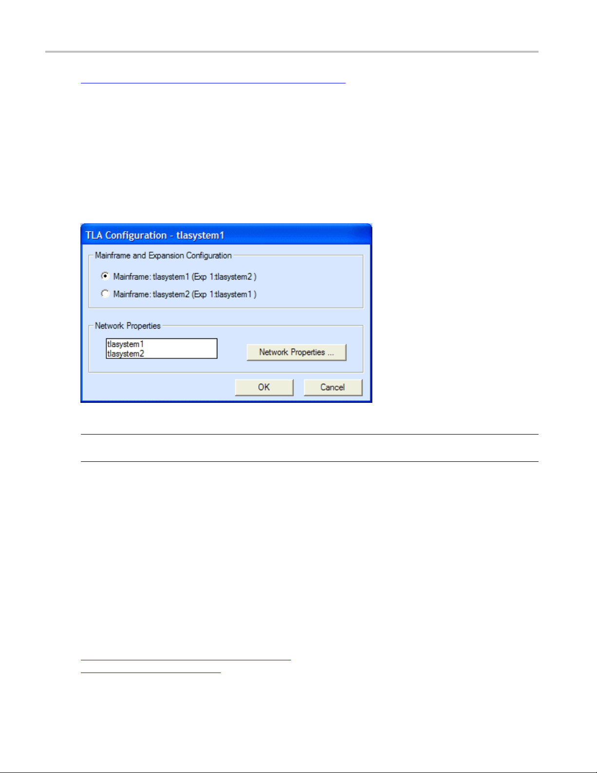
Configuring your TLA7000 without a TL708EX
Overview
Use this dialog box to change the configuration of your TLA system when you only have two mainframes
connected with a TekLink cable. Specify which TLA is the mainframe and which one is the expansion
mainframe using this dialog box.
NOTE. This dialog is only accessible if the system has no more than two TLA7000 mainframes connected
with a TekLink cable.
To use the TLA Configuration dialog box, perform the following steps:
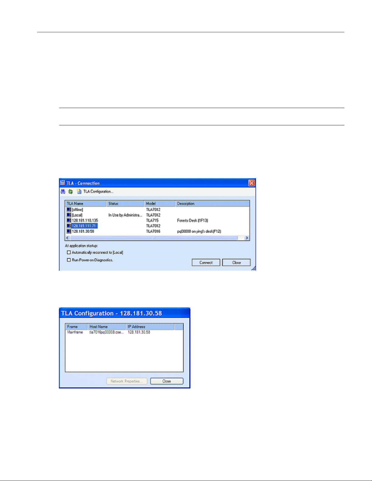
1. Select Choose TLA from the File menu to open the TLA Connection dialog box.
2. Select an instrument, and then click the TLA Configuration button.
The TLA Configuration dialog box opens.
3. Select the desired configuration under Mainframe and Expansion Configuration.
4. To edit the network properties, select the TLA7016 instrument, and then click the Network Properties
button.
Related Topics
Connect to a Networked Instrument (see page 5)
Network Properties (see page 8)
4 TLA Online Help
Page 27
Getting Started Connect to a Networked Instrument
Connect to a Networked Instrument
From the TLA Connection dialog box, select the instrument that you want to connect to and click the
Connect button. Customize your startup by specifying whether to run power-on diagnostics and whether to
automatical
NOTE. If you choose to automatically reconnect to an instrument, the next time that you start the TLA
application, it will open in the offline mode.
To change your customized settings, select Choose TLA from the File menu. Note that the TLA Server
must be running on your instrument to populate the TLA Connection dialog box. To start the TLA Server,
click the TLA Server Control icon in the Windows system tray and select Start TLA Server. The TLA
Server does not run on your PC.
ly connect to a selected instrument each time you login.
To view the configuration of your TLA system, select a n instrument, and then click the TLA Configuration
button. (This button is not active until you have selected a TLA.)
TLA Online Help 5
Page 28

Getting Started Connect to a Networked Instrument
The instruments that are listed in the TLA Connection dialog box are determined by the network search
properties. Change the properties by clicking the
Search Preferences dialog box.
TIP. If you do not know the host name or IP address, select the Locate TLA systems on local subnet check
box. This will find any TLA instrument that is connected to the same subnet a s your host PC in the search.
icon and enter your preferences in the Network
What would you like to do next?
About the LA Setup Window.
Learn
Learn About the LA Trigger Window. (see page 163)
(see page 15)
6 TLA Online Help
Page 29

Getting Started Network Search
Network Search
Use the Network Search dialog box to set the preferences for the search criteria that the Connection dialog
box uses. Open the dialog box by clicking
1. Select Locate TLA systems on local subnet to include any TLA system connected to the same subnet
as your host PC in the search.
in the Connection dialog box.
2. Select Include these hostnames or IP in search to include the instruments listed in the Hostname or IP
text box in the search. If you know the name of an instrument, add it directly by entering the name
in the Add hostname or IP text box and then clicking the Add button. This adds the instrument to
the search but not to the Connection dialog box. The instrument must be found in the search to be
addedtotheConnectiondialogbox.
3. To remove an instrument from the search, select it from the Hostname or IP text box, and then click
the Delete Selection button.
4. To update the Hostname or IP text box, click Replace All with TLAs found on subnet.
5. Click the Search button to search the subnet according to the criteria that you have set, and update the
Connection dialog box. When the search is completed, the Network Search dialog box closes and
the Connection dialog box is updated.
Related Topics
Connect to a Networked Instrument (see page 5)
Overview of Connection Choices (see page 3 )
TLA Online Help 7
Page 30

Getting Started Network Properties
Network Properties
Overview
Use the Network Properties dialog box to configure the Host Name and IP address of your networked
instruments
Behavior
This dialog box appears when you click the Network Properties button in the TLA Configuration dialog
box. The Default name is a combination of the TLA7016 Interface Module model number and the serial
number. Select Use the following Name to assign a unique name. The TLA7016 Interface Module will
attempt to get its IP address automatically when Obtain Address Automatically is selected.
NOTE. This dialog is only supported on TLA7016 mainframes.
.
8 TLA Online Help
Page 31

Getting Started Options of Powering On and Off
To Use
1. Select either Default name or enter one of your choosing in the Use the following Name text box.
2. Click the Look Up IP Address button to find an IP address.
3. To specify an IP address, select Use the following Address, and then enter the IP Address, Subnet
Mask, and Gateway.
Options of Powering On and Off
To power on the analyzer without the TLA application starting, perform the following steps:
1. Access th
2. Click TLA700SU.bat and use your right mouse button to click Edit.
3. Enter the characters REM in front of the following line:
C:\ WINDOWS\COMMAND\START /MAX .\TLA700.EXE.
Specify how you want the instrument to power off through a program labeled Mainframe Utilities located
in the Windows Control Panel.
The utility also provides a screen dim mode to reduce the b rightness by 60%. Refer to the help provided
with the utility for more information on both functions.
TIP. Access the Mainframe Utilities by clicking the Windows Start button, pointing to Settings and Control
Panel, and then clicking Mainframe Utilities.
e System folder using the following path: Program Files\TLA \System.
TLA Online Help 9
Page 32

Getting Started Examine the Waveform
Examine the Waveform
Use the Waveform window controls to view and measure the waveforms. Here are some suggestions
for getting started:
Use the scroll bars to display data that is currently off-screen.
Click in the
Select Cursor 1 and drag the cursor handle to a new location. The handles shown along the top of the
display ar
time readouts in the Cursor toolbar.
Click the button to display an external oscilloscope waveform.
Click the button to display a MagniVu waveform.
To zoom data, click and drag the mouse over the area that you want to zoom. The window will zoom
to the data when you release the mouse button.
To increase the size of the area in which the data is displayed, select Full Screen from the View menu.
Click (Zoom Out) or (Zoom In) in the toolbar to change the horizontal scale.
Select a waveform header and the whole row is highlighted, making it easier to view.
Double-click (or any other waveform label). Change the color and size (size is
also c
and return to the Waveform window.
Clic
eforfine control; those at the bottom are for coarse control. Note the change in the cursor
hangeable directly) of the waveform in this property page. Click OK to complete the changes
k the + on the waveform label to expand the waveform into the individual signal elements.
toolbar and select a mark to jump to.
Drag the split box (above the top arrow of the vertical scroll bar) down to display a second data area
iew two different portions of the same acquisition memory.
to v
10 TLA Online Help
Page 33

Getting Started Viewing Other Types of Waveforms
Viewing Other Types of Waveforms
Add the MagniV
steps. (MagniVu Data
1. Click
2. From the Data Source list, select LA1 - MagniVu.
3. Select a Mag
4. Click the Close button when you have finished adding waveforms.
When viewing LA groups, view the data as busforms or as magnitude waveforms by right-clicking the
mouse over a data label and selecting either Display Busform or Display Magnitude. Expand the group
into the i
Or,
1. Double-click the label of a signal waveform. (If you do not have a group waveform, click
2. From the Waveform Properties tab, click the Options button.
3. Select
4. Click OK. The waveform is displayed accordingly.
ndividual busforms by clicking the + on the label.
an LA Data Source, and choose a group to display. Confirm and exit the dialog box.)
u version of the data at any time by clicking the
(see page 407) is always acquired with your other data.)
(Add Waveform) in the toolbar.
niVu waveform or group (for example, Mag_A3), and click Add.
Busform or Magnitude, and click OK to close the Waveform Options dialog box.
button or use the following
, select
Related Topics
i-Signal Magnitude LA Waveforms
Mult
Multi-Signal Busform LA Waveforms (see page 243)
(see page 244)
TLA Online Help 11
Page 34

Getting Started Viewing a Magnitude Waveform Sample
Viewing a Magnitude Waveform Sample
1. Click in the toolbar to start the New Data Window wizard.
2. Click Waveform and click the Next button.
3. Click Add Dat
4. Enter the following path into the File name box, or click browse to navigate to the SampleSystem.tla
file:
C:\Program Files\TLA700\Samples\TLA700 Samples\Data Files\SampleSystem.tla
5. Click the Add button. The SampleSystem data source is added to the list of data sources.
6. Click LA under SampleSystem.tla and click the Next button.
7. Enter a name for the new data window or use the default name and then click the Finish button.
8. Choose one of the following procedures:
a. Right-
Or
a. Double-click the new Down Count label.
b. Click Options and select Magnitude, click OK twice to close the dialog boxes.
c. Click the Zoom buttons to view a sawtooth w aveform. The waveform is a graphic representation
of counter data.
aSource.
click the mouse over any data label and select Display Magnitude.
12 TLA Online Help
Page 35

Getting Started Examine the Listing Data
Examine the Listing Data
Here are some suggestions for viewing Listing window data:
1. Use the scroll bars to display data that is currently off-screen.
2. Click
3. Drag the cursor handle to a new location. The handles shown along the left of the display are for
fine control; those at the right are for coarse control. N ote the change in the cursor sample number
and delta t
4. Click the toolbar Font buttons to change the display font size.
5. Drag the split box (beside the left arrow of the horizontal scroll bar) to display a second data area to
view two different portions of the same acquisition memory.
6. Double-click an address or data column label (for example,
column in this property page.
7. From the Column property page, try loading a symbol file: click the radix button box, choose the
Symbolic radix, click the Symbol File button, and choose a symbol file.
8. Confirm and exit the property page.
in the toolbar and select Cursor 1.
ime readouts in the Cursor toolbar.
). Change the attributes of the
TLA Online Help 13
Page 36

Getting Started Searching Selected Data
Searching Selected Data
1. Double-click a data entry in one of the columns of the Listing window. The data is now selected. Click
in the toolbar to copy the data to the clipboard.
2. Click
3. From the S ea
window or type in a new search name.
NOTE. Toaddasearchdefinition from another data source, click the Load button to open the Load
Search dialog box.
4. Click the Start from drop-down list to select where you want to start searching and enter the number of
occurrences to find in the occurrence text box.
5. Click the Search Options… button to open the Search Options dialog box and select what action you
want the logic analyze r to take when the search is successful.
6. Type a Description of the search in the Description text box.
7. From the Search drop-down list, select the data source.
8. Paste
area by pressing CTRL+V (the paste shortcut key combination). Use the same method for pasting a
quick entry into a trigger program definition.
9. Use the Group drop-down list to select the column from which you copied the data.
in the toolbar.
rch Definition drop-down list, select a saved search definition from the selected data
the data that you copied from the Listing window into the appropriate text box in the Find
10. Cli
ck Search Forward. The logic analyzer displays the next instance of the specified data. Once you
have defined the search criteria, click the Search Forward or Backward toolbar buttons for additional
searches.
14 TLA Online Help
Page 37

System Setup LA Setup Window
LA Setup Window
The primary function of the Setup window is to configure the LA module for compatibility with the system
under test. Use this window to do the following tasks:
Set thresholds
Set global setup and hold sampling
Specify sig
Name signals
Select filter and analysis tools
nal groups
To Use
1. From the TLA toolbar, click the Setup button, and then select your module, (for example LA 1, when
there is
2. Specify the type of sampling
3. Set the memory depth
4. Specify the storage option
5. Associate meaningful signal names
6. Create meaningful groups
7. Desk
NOTE. After defining the LA Setup window, you can immediately acquire data. To improve your acquisition
results, revise your Trigger window and adjust your data window properties.
more than one LA module).
(see page 29).
(see page 27).
(see page 24).
ew the probes
(see page 19).
(see page 16).
(see page 20) to probe channels.
Behavior
The LA Setup window and the associated Trigger window determines what data will be acquired. Each
module has a Setup window and Trigger window; they are set up individually and used separately for
their particular purposes. Configure the Setup window before the Trigger window; many of the Setup
indow settings affect Trigger window selections.
w
TIP. To duplicate the current setup for another LA module, open to the File menu and click Save Module.
For quick access to the Setup window on the TLA7012 Portable Mainframe or on the TLA6000 series
instrument, press the Setup button on the front panel. Continue to press the Setup button to cycle through
all of the acquisition module Setup windows in the system.
TLA Online Help 15
Page 38

System Setup Sampling
Base Signal
A memory storage location for acquisition data.
Prime Signal
An expanded memory location for high speed data acquisition. The log
signals for storage when the speed of acquisition exceeds that available for base signals alone. P rime
signals have an exponent added to the base name.
Creating a prime signal increases the memory available and removes the base signal from the
Signal Mapping area.
Sampling
The logic analyzer supports two basic types of sampling: asynchronous and synchronous, each displayed
in its own tab on the sampling screen. A third type of sampling, custom sampling
available only when a support package
the name of the support package.
When you use asynchronous sampling, the logic analyzer generates its own clock signal at regular, fixed
intervals to sample data from the system under test. Acquisitions taken with asynchronous sampling are
often referred to as timing acquisitions, and are best viewed in the Waveform window.
When you use synchronous sampling, a clock from the system under test samples the signal. This clock
can be a fixed frequency, or it may be highly variable. Acquisitions taken with synchronous sampling are
often referred to as state acquisitions and are best viewed in the Listing window.
ic analyzer creates prime
(see page 373) is
(see page 16) is loaded on the logic analyzer. The tab label includes
To Use
1. From the TLA toolbar, click the Setup button, and then select your module, (for example LA 1).
2. Click the Asynchronous, Synchronous, or support package tab.
3. Adjust the controls as needed for your situation.
NOTE. Sampling and state speeds will vary by module.
Microprocessor or Bus Support Package
A microprocessor or bus support package is a software application that allows the logic analyzer to
acquire and disassemble microprocessor data or data from a bus.
Some support packages include a hardware probe adapter that is attached directly to the
microprocessor in the system under test to capture microprocessor signals.
The LA Setup window shows which support package is currently installed.
16 TLA Online Help
Page 39

System Setup Synchronous Sampling: Define Single Clock
Synchronous Sampling: Define Single Clock
The default controls for the Synchronous tab establish global settings for setup and hold across all signals
in the module. Use this tab to specify a single clock from the system under test for your synchronous clock.
Change the se
ttings for individual signals in the Signal Mapping area
To Use
1. From the TLA toolbar, click the Setup button for your module.
(see page 20).
2. Click the S
3. If necessary, click the drawer arrow (<||||) to open the Define Single Clock panel.
4. Select the clock source from the Single Clock Source list.
5. Adjust the Global Default Threshold. This setting should match most of the signals that you are
sampling with the current module.
6. Enter a maximum clock rate or the minimum clock period for your module.
Setting this value helps scale the T
greater than your maximum clock rate; an accurate value is not needed.
7. Select the clock edge and adjust the busform to match your SUT setup and hold times; drag the
whole busform or just the edges.
ynchronous tab.
and Thelements in the diagram. Enter a value that is likely to be
s
Behavior
When you select the DDR check box, the logic analyzer automatically selects the appropriate sampling
points based on the Max Clock Rate and currently selected sample points. If you manually select two
nts, the DDR check box is automatically selected.
poi
TLA Online Help 17
Page 40

System Setup Synchronous Sampling: Define Compound Clock
Synchronous Sampling: Define Compound Clock
Use the Define Compound Clock controls to set up a compound synchronous clock. This is a global
setting for the module. Use this tab to change the settings for individual signals in the Signal Mapping
e
area (see pag
To Use
1. From the TLA toolbar, click the Setup button for your module.
20).
2. Click the S
3. If necessary, click the drawer arrow (||||>)toopentheDefine Compound Clock panel.
4. In the Master Sampler table, definethesynchronousclocksourcesbyselectingtheclocksand
qualifiers from the drop-down list within each table cell. The graphic shows the resultant settings.
5. Adjust the Default Threshold. This setting should match most of the signals that you are sampling
with the current module.
6. In the Speed drop-down list box, select a bandwidth for the module you are using. If you select
Max, and reload a different module, the d efault setting uses the maximum speed of the module (only
avail
7. Set the Pipeline Delay for all acquired signals.
8. Enter the minimum clock period for your module.
vior
Beha
When you display the Define Compound Clock panel, the logic analyzer uses the default values you
igned in the Define Single Clock p anel, including Min Clock Period, T
ass
of sample points.
you defined a DDR sampling structure in the Define Single Clock panel, the Sampler Definition area
If
indicates two sample points corresponding to the DDR definition. However, you will note that the
Compound Clock diagram differs significantly from the Single Clock diagram.
ynchronous tab.
able with TLA7000 series logic analyzer modules).
and Th, and the number
s
NOTE. To c o nfigure individual channels with varying numbers of sample points, use Compound Clocking
and then adjust each signal definition using the Signal Sampling Screen
18 TLA Online Help
(see page 26).
Page 41

System Setup Deskew Panel
Deskew Panel
Deskew allows you to compensate for propagation delays in your circuit traces that differ from your design
due to the location of the probe header. Perform the deskew on all signals in the module by clicking the
Deskew butto
This procedure applies deskew to all signals in the module.
1. From the TLA toolbar, click the Setup button for your module.
2. Click the Synchronous tab.
3. Use the Se arch Range and Accuracy controls to adjust deskew settings for all signals for the connected
modules.
4. Click the Deskew button.
The logic analyzer displays the Deskew progress bar in the Status area during deskew.
n. You can also deskew individual signal groups
(see page 19).
Group D
This pr
Deskew panel. After you make any changes to selected signals in the group, the Global Values check box
will be cleared. This indicates that these signals will not track changes to the parameters in the Global
Sampling diagram.
1. From the TLA toolbar, click the Setup button for your module.
2. Click the Synchronous tab.
3. In t
4. In
5.I
6. Click the Deskew button to deskew the highlighted signals in the group.
To return signals to the global value, select the Use Global Values check box.
eskew
ocedure deskews selected signals within a defined group based on parameters you set in the
he Group Management area, adjacent to the Signal Mapping area, create and name a signal
group (see page 24).
the group card, click the Local Sampler Definition thumbnail
to open the Signal Sampling screen.
n the Signal Sampling screen, verify that the signals that you want to deskew are highlighted in
the Signal tree.
The logic analyzer displays the Deskew progress bar in the Status area during deskew.
in the group card header
TLA Online Help 19
Page 42

System Setup Signal Mapping Area
Behavior
Before deskew, the logic analyzer displays all of the signals in the local Setup and Hold diagram on top
of one another. After the deskew, the logic analyzer displays the signals as a fuzz band
the Setup and Hold diagram.
(see page 20) in
Related Topic
Signal Samp
ling Screen: Adjusting Setup and Hold Values
(see page 26)
Fuzz Band
The logic analyzer displays signals as a fuzz band within the Setup and Hold diagram. The display
shows the signal frequency as a temperature gradient where the warmer or brighter colors represent a
higher density of signals. The cooler or darker colors represent areas where fewer signals overlap.
Click an area in the fuzz band to select a signal from the tree. Adjust the Setup and Hold values for
the selected signal or move the signal within the fuzz band.
Signal Mapping Area
The Signal Mapping area allows you to view the physical resources of the module. It also provides a
centralized area for viewing signal activity, signal type and characteristics, sampling configuration, and
base
(see page 16) and prime (see page 16) signal participation.
Use the Signal Sampling screen to configure the threshold, polarity, type, and the sampling definitions for
individual signals. Access the Signal Sampling screen either through the right-click menu (by clicking the
activity indicator in a channel cell for the signal), or by clicking the Local Sampler Definition thumbnail
next to the probe section header
20 TLA Online Help
Page 43

System Setup Signal Mapping Area
Behavior
The Signal Mapping area is a collection of cells organized into a two-dimensional matrix. The columns
represent the probe leads (consisting of probe sections in a 7 – 0 order, plus the clock and qualification
leads). The rows repres ent probe sections, with adja
and rows cannot be individually sized, and header cells cannot be renamed.
The Signal Mapping area may display logical signals that have no physical counterpart (such as status
bits or static bits).
Sampling Definition Thumbnails. When a module is sampling in synchronous sampling mode or custom
sampling mode, the Thumbnail column displays images representing the sampling definition of the probe
signals. In addition to identifying the characteris
thumbnail is a button used to display the Signal Sampling screen.
NOTE. The logic analyzer does not display thumbnails in the asynchronous sampling mode.
Click the thumbnail image to open the Signal Properties screen to set the sampling offsets for base (see
page 16) and prime (see page 16) signals.
cent rows representing paired probe sections. Columns
tics of the probe section sampling characteristics, the
Thumbnail type Description
Basic sampling, rising or falling edge, single
Compound sampling, one or more rising or falling edges, no
qualifier
Same as above with additional sample point
Basic sampling, rising or falling edges, two sample points
Compound sampling, one or more rising and falling edges,
no qualifier
Compound sampling, one or more edges with one or more
qualifiers.
Compound sampling, one or more rising and falling edges,
one or more qualifiers
Varies (variable sampling), signals i
different sampling characteristics
The clocking figure m ay have any of the images shown above;
the rising edge shown for illustration
xxx
n a group or section have
sample point
purposes only
By default, the displayed thumbnail corresponds to the Global Sampling Definition. When you change
an individual signal sample point (either manually or as a result of the deskew function), the thumbnail
displays the Varies image, indicating that at least one signal in the section has a different sample point.
Thumbnails appear for base signals and group cards and are not available for prime signals, status bits,
or custom sampling contexts.
TLA Online Help 21
Page 44

System Setup Signal Mapping Area
Probe Section Header
The logic analyzer uses the Probe Section Header to identify base (see page 16) (true sources) and prime
(see page 16) (cloned data streams from the base source) signals.
The Probe Section Header displays the name of the probe section (A0, A1, A2). Base probe sections (true
sources) display the name left-justified in the header cell.
Prime probe sections (data streams cloned from the base source) are labeled with the base name and an
1
exponent (A0
placed sequentially below their Base probe section (A0 is followed by A0
,A02). The labels are right justified in the header cell. Prime probe sections are always
1
,A02).
Signal Column Header
Each probe lead is assigned a cell below its signal number. The Signal column header is a display item
only and has no interactive behavior.
Clock / Qual Header
Two columns identify the clock and qualification lead for each probe section that has one of these
additional leads. The left column permanently displays the resource name, for example CK0(), and the
right c olumn contains the Channel / Signal cell. The Channel / Signal cell initially shows the resource
name, but you can enter your own name. For probe sections that do not have a clock, qual, or both,
both cells in the column are disabled.
Group Participation Bar
Running horizontally across the top of each Signal cell, is a color-pattern bar that indicates how signals
participate in a selected group or multiple groups. The following table shows examples of two adjacent
cells.
Appearance Description
Default appearance. The channels do not participate in any group.
Group participation. The signals participate in the currently selected group.
Multiple group participation. The signals participate in the current selected
group and at least one other group.
Other group participation. The signals participate in a group other than the
selected group.
xxx
Activity Indicator
The right-most region of a base Channel / Signal cell displays activity information and a means to
modify the operating characteristics of the signal. Instead of activity indicators, p olarity indicators are
displayed for prime signals, status b its, static bits, or custom signals using the crossbar (custom storage
signals). Although you cannot change most of the operating characteristics of these types of signals,
22 TLA Online Help
Page 45

System Setup Signal Mapping Area
change the polarity by right-clicking the polarity indicator and by selecting the Invert Signal Polarity from
the right-click menu.
The following table s hows examples of the polarity indicators and activity indicators.
Appearance Description
polarity. The indicator appears as a vertical bar in the upper cell.
or the inverted, high polarity, the indicator appears as a vertical bar
ning signal.
xxx
Click the
Normal, high
Normal, low polarity. The indicator appears as a zero in the lower cell.
Inverted, low polarity. The indicator appears as a zero in the upper corner.
Similarly f
in the lower cell.
Transitio
green and yellow activity indicator to display the Signal Sampling panel, where you set the signal
threshold value and polarity.
Static and Status Bits
These are additional signals to use in group definitions for triggering.
Related Topic
Group Management_Area (see page 24)
TLA Online Help 23
Page 46

System Setup Group Management Area
Group Management Area
Use the Group Management area to organize the probe signals to match the configuration of the system
under test. Depending on your application, match the signal groups
data buses, o
individual group card with a group name and grid. Group cards contain additional elements, such as an
activity indicator and thumbnail to help you define signal properties within the signal group.
r match the signal groups to other signals of interest. Each signal group is displayed as an
To Use
1. From the TLA toolbar, click the Setup button for your module.
2. To create a new group, click the + icon at the top of the Group Management area.
(see page 30) to the address and
a. Enter a group name
b. In the Si
drop the signals to the group card.
c. To rear
within the group card grid. Alternatively, right-click the mouse and select Reverse Signal Order
to change the MSB-LSB order of the signals.
3. After creating multiple group cards, rearrange them by dragging and dropping them in the Group
Management area.
4. Click the thumbnail or the activity indicator in a group card to access the Signal Sampling screen
page 26) to adjust signal thresholds or to adjust the setup and hold requirements for signals.
NOTE. Activity indicators and thumbnails might not display depending on the sampling you have defined.
5. Expand and collapse group cards to make room for more cards on the screen using the right-facing
arrow in the upper left corner of the group card.
gnal Mapping area, select individual signals or entire probe sections, and then drag and
range the order of signals within a group, drag and drop them from one location to another
(see page 25) for easy identification.
(see
Behavior
Create any number of group cards. Each group can contain any combination of module signals; you are
not restricted from mixing or repeating signals from various groups.
Groups are used in other displays and setup controls, such a s the Waveform and Listing windows, and
the Trigger window. The order of the groups in this table determines the presentation order of groups in
other parts of the application.
24 TLA Online Help
Page 47

System Setup Signal Sampling Screen: Setting Thresholds
Support Packages
If a microprocessor support package is loaded, the signal groups are already defined. You should not
change or delete these groups; doing so can lower the accuracy of disassembly analysis. However, you still
have the option of adding and deleting new groups.
Related Topic
Signal Mapp
ing Area
(see page 20)
Group Name
Each group must have a unique name. When you use the same name as a previous group, the
application prefixes your name with a number. For example, if you try to name a group, MyGroup,
and another group already exists with the that name, the application will redisplay your group name
as 1:MyGroup.
Use the default name, or enter another name as long as it is unique. The names will appear in the
Listing and Waveform windows. There is no limit to the number of groups to create.
Signal Sampling Screen: Setting Thresholds
Use the Signal Sampling screen to set the probe signal characteristics appropriate to your system under test.
To Use
1. From the TLA toolbar click the Setup button for your module.
2. In the Signal Mapping area, select one or more cells.
ick the Activity Indicator in one of the selected cells. Alternatively, from the right-click menu,
3. Cl
select Signal Sampling.
4. Co
5. Use the slider or Preset contr ols to set threshold values for the highlighted items.
6. Click Normal or Inverse to set the polarity for the highlighted items.
NOTE. If you highlight a prime
becomes available (no slider highlights in the threshold graph). Prime signals do not have thresholds.
TLA Online Help 25
nfirm the signals you want to work with are highlighted in the Signal tree. Clicking an item
removes the existing highlighting. (Press and hold
items in the Signal tree.)
(see page 16) signal in the Signal tree, no corresponding threshold control
CTRL+Click or SHIFT+Click to highlight multiple
Page 48

System Setup Signal Sampling Screen: Adjusting Setup and Hold Values
Behavior
Changes you make to the threshold are immediately applied to the signals that you highlighted (see
page 27) in the Signal tree.
NOTE. Highlight a different set of signals from the "selected" set of signals (the signals you selected
in the Signal
Use one of the buttons adjacent to threshold graph to assign the threshold value to more signals than the
ones you'v
several "s elected") click the Selected Signals button to assign the threshold to the selected set of signals.
Similarly, click the Probe Sections button to assign the threshold to all signals in a probe section to w hich a
highlighted signals belongs. The buttons are arranged top to bottom in increasing scope.
NOTE. Not all buttons will be enabled for all types of highlighting and selecting. Depending on your
module type, you might have fewer or more buttons available.
Mapping area).
e highlighted. For example, if you have highlighted only one signal in the tree, (and you have
Related Topic
Signal
Sampling Sc reen: Adjusting Setup and Hold Values
(see page 26)
Signal Sampling Screen: Adjusting Setup and Hold Values
Use the Signal Sampling screen to a djust setup and hold times for signals at the local (probe section or
p) level when working with synchronous or custom sampling.
grou
To Use
1. From the TLA toolbar, click the Setup button for your module.
lect the Synchronous tab (or custom sampling to adjust signals for a loaded support package).
2. Se
3. Click the Local Sampler Definition thumbnail
apping area or in the group card to open the Signal Sampling screen (the image on the thumbnail
M
differs depending on your setup).
4. Click to select a signal in the tree (
Alternatively, click the busform in the clocking diagram. Repeated clicking on a busform will cycle
through the signals in the order they are displayed in the Signal tree.
CTRL or SHIFT to select multiple signals) in the Signal tree.
intheprobesectioncolumnintheSignal
5. Adjust the local setup and hold values for your signal by dragging the Setup or Hold indicators,
dragging the entire busform, or by entering specific values in the boxes.
26 TLA Online Help
Page 49

System Setup Acquisition Options
When you select more than one signal (within the same sample or across samples) the logic analyzer
displays an open selection outline around each of the signals.
Interactions Between Global and Local Sampling Definitions
When you first
open the Signal Sampling screen, the default settings are based on the global default
values. When you change a local setting, the setting is no longer affected by changes that you make at
the global level.
If you work in a local context and you change the global settings, any local settings that you have not
manually changed will be updated to the global settings. To reestablish the local value connection with
the global values, click the Use Global Values check box. The check box affects the T
of the current highlighted signals
(see page 27) in the Signal tree. The checkboxisdisabledwhenno
and Thvalues
s
signals are highlighted.
Related Topics
Signal S
ampling Screen: Setting Thresholds
Group Deskew (see page 19)
(see page 25)
Highlighted vs. Selected Signals
In the sample tree structure below, signals C2(3), C2(2), and C2(1) were selected and highlighted
when you first opened the Signal Sampling screen. Any changes that you made to the highlighted
signals were automatically applied.
When you click signal C2(5), the signal becomes highlighted while signals
C2(3), C2(2), and C2(1) remain selected, but not highlighted. Any changes
that you make in the Signal Sampling screen will be applied to highlighted
signals, in this case, just C2(5). This gives you the flexibility to change
signals by highlighting them without having to close and reenter the Signal
Sampling screen.
Highlighting and selection apply to both sides of the Signal Sampling
screen: changing thresholds and changing setup and hold times. In the
case of thresholds, the threshold slider highlights based on which signals
you have highlighted. When you move the slider, only the highlighted
signals are affected.
When used with thresholds, the highlighted signals determine which
buttons on the left side of the Signal Sampling screen become available for
changing thresholds.
xxx
Acquisition Options
The acquisition options determine the data to store. The options that are available depend on the sampling
type that you specify.
TLA Online Help 27
Page 50

System Setup Acquisition Options
To Use
1. From the TLA toolbar, click the Setup button for your module.
2. Select your sampling type (synchronous, asynchronous, or custom).
3. Select Samples to store only the samples you acquire (default).
4. Select 63-Sample Blocks to store 31 samples before your stored sample and 31 samples after your
stored sample. (Use conditional storage in Trigger to store only events of interest).
5. Select Samples + Glitches (Asynchronous) or Samples + Violations (Synchronous) to store both
the acquired sample and glitch or violation data.
Behavior
Sampling type
Asynchronous
Synchronous Samples - stores samples only
xxx
Acquisition options and resulting data
Samples - stores samples only
63-Sample Blocks - stores b locks of data around each
stored sample
Samples + Glitches
glitch data
63-Sample Blocks - stores b locks of data around each
stored sample
Samples + Violations
and setup & hold data
(see page 28) - stores both signal and
(see page 28) - stores both samples
NOTE. Selecting Samples + Glitches or Samples + Violations decreases the maximum memory depth by
half and decreases the maximum sampling speed.
Related Topics
Sampling (see page 16)
LA Setup Window (see page 15)
63-Sample Blocks Mode (see page 185)
Samples + Violation Storage Mode
The Samples + Violation storage mode captures both setup and hold violation data and regular data
for each signal. This mode limits memory depth to half of the memory depth.
Samples + Glitches Storage Mode
The Samples + Glitches storage mode captures both glitch data and regular data for each signal. This
mode limits memory depth to half of the maximum depth and limits the sample period to 4 ns.
28 TLA Online Help
Page 51

System Setup Sample Storage
Sample Storage
Use the Samples per Signal setting to specify the total number of samples acquired for each signal by
the logic analyzer.
To Use
1. From the TLA
2. In the Setup window, use the slider to set the Samples per Signal.
toolbar, click the Setup button for your module.
Behavior
For a give
the time period over which samples are taken. A faster sample r ate provides a more detailed record of
a shorter sampling duration.
If you do n ot require the maximum number of samples, select a lesser value. This will improve the
response time for s earch and zoom operations.
NOTE. Selecting Samples + Glitches reduces the available memory by one half. Double the available
memory by increasing the sample rate below a certain value in Asynchronous sampling. In Synchronous
sampling, double the available memory by increasing the maximum clock rate of the SUT clock rate
by red
n number of samples, there is a trade-off between the sample rate and the sample duration, and
ucing the clock period.
Related Topics
Selecting Memory: A General Approach (see page 100)
Acquisition Options (see page 27)
Merged Module Synchronous Sampling
If you use synchronous sampling w ith a merged module formation and you use a single clock source, you
onlyneedtoconnecttheclockleadfromthe master module to the clock source.
This condition is also true for qualifier lines.
Related Topic
Merge Modules Properties (see page 411)
TLA Online Help 29
Page 52

System Setup Highlight Signal Names Dialog Box
Highlight Signal Names Dialog Box
Use this dialog box to highlight signals by name.
1. From the toolbar, open the Setup menu and select your module.
2. In the signal mapping area, right-click and select Highlight Signal Names.
3. In the Highlight Signal Names dialog box, enter the text you want to find. For example, enter RESET
to highlight any signal name that contains RESET.
NOTE. Enter multiple strings, separated by spaces. The space-separated strings are logically ORed. That
is, the name that matches any one of the strings will be highlighted.
4. Select the highlight criteria.
5. Click OK.
Grouping
Group cards list the signals that make up each group. Use the group cards to do the following:
Create arbitrary collections of signals by dragging them from the Signal Mapping area.
Type the signal name in an empty cell in the group card grid or type the signal name in the Keystroke
Entry field (see page 31).
Arrange the signals in order of significance by clicking and dragging them within the group card; the
Keystroke Entry field automatically updates when you rearrange signals.
Establish o perating conditions on the logical groups to establish proper operating c onditions of the
logic analyzer.
Provide the appropriate logical relationship to the system under test.
There are several ways to delete signals within a group card:
Delete the signal name from the Keystroke Entry field.
Select a signal name within a cell and delete it.
SelectoneormoresignalsandpresstheDeletekey.
Select an individual signal and drag it to another g roup or to the Signal Mapping area.
When you delete a signal from a group card, the signals on the least-significant bit side of the deleted
signal move to fill the ga p created by the deleted signal.
30 TLA Online Help
Page 53

System Setup iCapture Analog Feeds
Keystroke Entry Field
Use the Keystroke Entry field to enter valid expressions for signals in the group card. Enter hardware
section notation variants (such as A3, A2(), E1(0–4)), and logical names. The field automatically
updates the section notation to individual hardware names. The field also applies logical names to
signals, if t
hey are available, such as when your logic analyzer has a bus support loaded.
iCapture Analog Feeds
Use the iCapture Analog Feeds dialog box to assign a digital data signal to the Analog Output of a
TLA6000 series logic analyzer or a TLA7000 series logic analyzer module.
Assign data signals in the following ways:
Select an individual channel; and then assign it to an analog output channel.
Select a group of channels; and then select the analog output channels to which you want them
assigned.
The Physical Module field, which is located at the top of the dialog box, allows you to select which logic
analyzer module channels you want to direct to an oscilloscope.
NOTE. iCapture Analog Feeds are only available on TLA6000 series logic analyzers or on TLA7000 series
logic analyzer modules.
e
To Us
From the TLA toolbar, click the iCapture button.
Behavior
der Analog Output Attenuation, select an attenuation level based on the amplitude of the signals being
Un
assigned. 5X Attenuation is best suited for small amplitude, high-performance signals for improved signal
to noise ratio. Please note that waveforms displayed on your oscilloscope will be displayed at twice their
normal height because the attenuating factor is 5X and not 10X.
TLA Online Help 31
Page 54

System Setup iCapture Analog Feeds
After selecting which module contains signals that you want to output, you use the contents o f Select
Channels to choose one or more specific signals to use as feeds for analog outputs. Select Channels
contains a drop-down list to choose the how digital signals are displayed.
The drop-down list provides the following display options:
By Group. This displays signals organized by group. Only groups that are defined in the LA Setup
window can be displayed using this option. In addition, a group can only be expanded if it contains
signals from the selected physical module.
By Probe. This displays signals that are alphanumerically organized by individual signal. All signals
are displayed when this option is selected, regardless of whether they are part of a group that is
defined in the LA Setup window.
By Name. This displays signals by name assigned to them from the LA Setup window. Signals that
have not been assigned custom names are not listed when using this selection.
Selecting Individual Signals
After you have chosen a digital signal to output, assign it to an analog output signal by clicking a signal
button under Assign To. Confirm that the digital signal was correctly routed by reviewing the analog feed
assignment information under Current Routing.
32 TLA Online Help
Page 55

System Setup iCapture Analog Feeds
Selecting Groups
When you select multiple digital signals to output, assign them to one or more analog output signals by
selecting the check boxes associated with the target signals. If you are interested in more digital signals
than you have analog outputs, use the Analog Feed Cycling buttons to cycle the selected digital signals
through the s
to guarantee that signal assignments to unselected outputs are preserved. To do so, select the check box
labeled Exclude signals assigned to unchecked outputs.
NOTE. The system reassigns digital signals only when the assigned digital signal is a member of the
signals that you specified for output in Selected Channels and the analog output signal to which the
digital signal is assigned is not selected.
If one or more of the selected digital signals are already assigned to an analog output, those signals are
highlighted under Select Channels. As you feed digital signals to the selected analog output signals, this
highlig
Use the following Analog Feed Cycling buttons to cycle the selected digital signals to the selected
analog
elected analog outputs. Direct the system to exclude signals assigned to unchecked outputs,
hting changes to reflect current signal routing.
output signals.
Assignsuptothefirst four (depending on number of analog output signals selected) digital
signals to the selected analog output signals.
Assigns the selected digital signals to the selected signal outputs in groups equal to the number
of signal outputs selected. The order in which the digital signals are assigned is from the bottom of
the list to the top.
Assigns the selected digital signals to the selected signal outputs, in groups equal to the
number of signal outputs selected. The order in which the digital signals are assigned is from the top of
the list to the bottom.
Assigns up to the last four (depending on the number of analog output signals selected) digital
signals to the selected analog output signals.
The Current Routing group box displays read-only details about the assignment of individual data signals
to analog outputs and the oscilloscope input signals to which they are physically connected. It also
rovides a System Inter-probing button to reassign oscilloscope destination of data signals.
p
TIP. To acquire the best possible signal-to-noise ratio on live waveforms through the analog probe outputs,
use an external oscilloscope when the logic analyzer acquisition is idle.
The iCapture Analog Feeds dialog box retains the signal assignment settings for each logic analyzer
represented in the System window. When using Analog Feed Cycling, assign signals using one of the
previously described control buttons, then close the dialog box. Later, when you reopen the dialog box,
resume assigning digital signals to analog outputs. However, if you change either the setup of groups or
any signal names, signal assignment settings will return to defaults the next time the dialog box is opened.
TLA Online Help 33
Page 56

System Setup Filter Definitions Dialog Box
When using the logic analyzer’s demultiplexing capabilities to acquire digital d ata, the analog output data
may not match the digital data. The analog output connector always gets the signal directly from what is
presentatthe
source signal and not from the probe tip. Looking at the LA Setup dialog box signal grid, to tell which
analog output signals will not m atch the digital data: Demultiplexed destination signals (pink background)
and s ignals forced to 1 or 0 (yellow background) will not match.
probe tip. For a demultiplexed destination signal, the digital data comes from the demux
Related Topics
System Inter-Probing (see page 57)
Changing Signal Routing (see page 74)
Setting Up Analog Feeds (see page 71)
Filter Definitions Dialog Box
From the toolbar, click the Filters button for your module.
Overview
Use this dialog box to display and manage all filters in the logic analyzer.
Behavior
The dialog box displays all modules and filters currently used by the logic analyzer. Use the tree controls
to expand and collapse the filter contents of the modules. Modules are listed first, followed by any loaded
data sources, and then the filters. Loaded data sources consist of a file name and a module name (for
example, System1.tla:LA-1).
To Use
Manage the fi lters using the toolbar buttons at the top of the dialog box, the right-click menu, or the
keyboard. By selecting a module in the dialog box, attach a n ew filter to the module, load an existing filter,
or paste a new filter using the clipboard contents and attach it to the module. By selecting a filter, cut, copy,
paste filter contents, load another filter’s contents from the Load Filter Dialog Box
or edit the filter’s contents through the Define Filters dialog box
Define Filter Dialog Box
Overview
(see page 36),orview
(see page 34).
The logic analyzer normally displays all data acquired by the probes from the target system. Frequently,
it displays data that you are not interested in. Use data filters to display only the data that you want to
seeinthedatawindow.
34 TLA Online Help
Page 57

System Setup Define Filter Dialog Box
Use filters to do the following:
Hide specificdata. Forexample,define a filter to hide data when all of the data in a group is equal to
FFFF.
Show specificdata.Forexample,define another filter to show data from a specificaddress.
Color specific data. For example, define a filter to display data to another address with a specified color.
Behavior
Filters are made up of clauses and events and are very similar to trigger definitions. Use the drop-down
list located at the upper left corner of each clause to select an action for each clause. All clauses in the
filter are evaluated beginning with the first clause.
When you select a Show or Hide action, fill in the event fields by using the drop-down lists or text boxes to
define the e vent that you want to either show or hide.
When you select a Color action, a color options button appears to select the color options for the filter.
After you select the color options, fill in the event fields to further definethedatathatyouwanttofilter
for the specific event.
Edit events and clauses by clicking the mouse at the right-end of the clause and either placing the mouse
over the indicator or right-clicking the mouse to display a context-sensitive menu.
Filters are saved as part of the module setups. Load filters when you need them. Edit and rename filters
as needed. When you apply a filter to a data window, the filter name is appended to the data label (for
example LA1: FilterA: A3 indicates that FilterA is attached to the A3 group of module LA1).
TLA Online Help 35
Page 58

System Setup Load Filter Dialog Box
To Use
Use this dialog box similarly to the trigger window by defining events and clauses for the filter. By default
the filter is enabled if it is not enabled, click the Enable this Filter check box.
Load Filter Dialog Box
Overview
Use this dialog box to load filter contents from any current or saved module setups.
Behavior
This dialog box loads filter contents from any saved module setup files or system setup files. The load
operati
load operation creates a new filter and attaches it to a module.
on replaces all settings in the selected filter (speci fi ed in the title bar). If no filter is selected, the
When a m
filters associated with that setup are listed in the center of the dialog box. If a module has a filter attached,
select and load that filter.
odule setup name or system setup name appears in the File Name text box, all modules and
To Use
Enter a module setup or a system setup name in the File Name text box or click the Browse button to
locate a module or system setup file. Select a filter from the setup to enable the Load button; click the
load button to load the filter.
E. If you load a filter that uses groups or signals that are not included with the module, the events will
NOT
be discarded. A message box will display, explaining what happened.
Related Topic
Load Filter Browser Dialog Box (see page 37)
36 TLA Online Help
Page 59

System Setup Load Filter Browser Dialog Box
Load Filter Browser Dialog Box
Use this dialog box to find TLA module or system setup files that contain filters. This dialog box is similar
to the standard Open Dialog Box. The main exception is that the Content area describes whether the
module has an
Use the dialog box to browse the file system for filters. After you select a file name and click the Open
button, the
Box (see page 36).
TIP. If you don’t see the file that you want, make sure that the file is a valid TLA module setup file or
system setup file. These files have the .tla suffix.
y filters defined.
dialog box closes and adds the file name to the File Name field of the Load Filter Dialog
Applying Filters
Whenyouapplyafilter to a data window, the filtereddataappearsasadatasource.Thefilter name is
appended to the data source name in a data window. Define the filter before you apply it to a data window.
1. In the Listing window, click the column name; in the Waveform window, click a waveform name.
2. Right-click the mouse and elect Apply Filter followed by the filter name.
Add a n
and selecting a filtered data source:
1. In the Listing window, click
2. In the new dialog box, select a data source that contains filtered data. For example, LA1:Filter1.
3. Select the data group that contains the filtered data.
4. Cl
ew column or waveform with filtered data by clicking the Add Column or Add Waveform icons
(the Add Column icon); in the Waveform window, click (the
Add Waveform icon),.
ick the Add button followed by the Close button.
TLA Online Help 37
Page 60

System Setup Color Options Dialog Box
Color Options Dialog Box
Use this dialog box to control the color of groups in the data window.
1. Select a filte
2. Select Color from the filter definition.
3. Click the button to the right of the drop-down list to open the Color Options dialog box.
4. Determine whether you want to use separate colors for an individual group or the same color for
all groups.
5. Click the color button to select the foreground and background color from the color matrix.
In addition to using a basic color, click More Colors… at the bottom of the color selection box to
define custom colors.
6. Click OK to close the dialog box.
r in the Filter Definitions dialog box and then click
Signal Import and Export Formats
The Signal import and export uses a structured text file format to organize the import and export
mation. Only formatted text files can be processed by the parser.
infor
The import or export file is separated into multiple lines by EOL (EOL can be CR, LF, or CRLF). During
ting or exporting, the parser processes one line at a time. The following lines are allowed in the file:
impor
Comment Lines
rol Lines
Cont
Information Lines (see page 45)
(see page 43)
(see page 43)
to open the filter.
ck Sample File
Cli
(see page 41) to view an Import/Export file.
Related Topics
Signal Setup Import Dialog Box (see page 41)
Signal Setup Export Dialog Box (see page 40)
Signal Setup Import Behavior (see page 38)
Signal Setup Import Behavior
Be aware of some of the behavior of the logic analyzer when it imports signal setup files:
38 TLA Online Help
Page 61

System Setup Signal Setup Import Behavior
The logic analyzer detects the delimiters used in the imported file. Therefore it is important to use
only one delimiter in the file. If you need to embed the delimiters in a signal name or group name,
enclose the na
The import operation will update the signal setup parameters related to the selected fields. For
example, if a
without any warnings. Similarly, if there are two lines in the imported file setting for the same signals,
the second line receives the new name.
The import operation will not change the signal setup parameters related to unselected fields. A
skipped field (an empty field name between two delimiters) acts as an unselected field.
User-defined signal names must be unique. If an imported user-defined signal name exists, the two
signals will exchange their user-defined names (for example, if you have A0(0):A and A0(1):B, and
you set A0(1) to A, the result will be A0(0):B and A0(1):A).
If an imported file contains a definition for a signal that does not exist, the definition will be ignored
and a warning message will be saved in the error log file. You may experience this when importing a
file to a narrow module.
If an imported file does not contain definitions for all the signals of the logic analyzer, the definitions
of the missing signals remain unchanged. This may happen when you import a file to a wide module.
me with quotes.
user-defined s ignal name is selected, the old name will be replaced by the new name
The parser processes one line at a time. It will stop processing on any unrecognizable line and then
display an error message.
All w arning and error messages will be written to a file named ImportExportError.log in the same
location as the import file.
TLA Online Help 39
Page 62

System Setup Signal Setup Export Dialog Box
Signal Setup Export Dialog Box
Overview
Use this dialog box to export signal setups to a text file. Thesetupscanthenbeimportedbyanother
logic analyz
Behavior
This dialog box allows you to save the setups to a text file listed in the Export Path box. Click the Browse
button to save the file to a folder of your choosing. You have the choice of exporting individual signal
information or group information by selecting the appropriate Export Selections. If you select Export
Signal Information, specify the type of information that you want to export by selecting one or more of
the check boxes. Select one of four field delimiters to separate the fields within the file; an empty field is
represe
Any warning or error messages are saved in a log file in the same location as the exported file.
er.
nted by two c onsecutive field delimiters in the file.
To Use
t Export Signal Setup… from the File menu. Specify a file name and the path to the file. Use the
Selec
other selections in the dialog box to define the signal information and delimiters. Click the Export button
to export the file.
Related Topics
Signal Setup Import Dialog Box (see page 41)
Signal Import and Export Formats (see page 38)
Signal Setup Import Behavior (see page 38)
40 TLA Online Help
Page 63

System Setup Signal Setup Import Dialog Box
Signal Setup Import Dialog Box
Overview
Use this dialog box to import signal setups from a saved location.
Behavior
This dialog box allows you to specify the signal setup infor
file location in the Import Path box or click the Browse button to browse the file system for the file. The
setups are normally saved in a text file.
Select the Automatically detect from file to import all fields from the import file. Select Custom options to
specify the fields that you want to import by selecting one or more custom options. If you try to import
a field that does not exist in the import file, the logic analyzer will display a warning message. Click
the Import button to import the setups. Warning and error messages are saved in a log file in the same
location as the imported file.
mation that you want to import. Specify the
To Use
Select Import Signal Setup… from the File menu while the Setup window is active. Locate the import
specify the import options in the dialog box, and then click the Import button.
file,
Related Topics
Signal Setup Export Dialog Box (see page 40)
Signal Import and Export Formats (see page 38)
Signal Setup Import Behavior (see page 38)
Sample Signal Setup File
The following file shows an example of the different parts of a Signal Import/Export file.
//////////////////////////////////////////////////////////////////////////////
// TLA Signal Import/Export File
// Created on June 10, 200
// by TLA Import/Export Utility Versi on: 1.0.001
// (Field Delimiter: <Tab>)
//////////////////////////////////////////////////////////////////////////////
//////////////////////////////////////////////////////////////////////////////
// Remove all user-defined signal nam es
//+ResetAllSignals
//
TLA Online Help 41
7 at 16:05:27
Page 64

System Setup Sample Signal Setup File
// Remove all groups
//+RemoveAllGroups
////////////
//////////////////////////////////////////////////////////////////////////////
// Signal def
//+SignalFormat : HWName UserName Polarity Compare
//////////////////////////////////////////////////////////////////////////////
C0(7) NMI - TRUE
C0(6) IGNNE# - TRUE
C0(5) EADS# - TRUE
C0(4) SRES
C0(3) HOLD - TRUE
C0(2) KEN# - TRUE
C0(1) LOCK# - TRUE
C0(0) RDY#= - TRUE
Q3 Q3 - TRUE
Q2 Q2 - T
Q1 Q1 - TRUE
Q0 Q0 - TRUE
CK3 CLK - TRUE
CK2 RDY# - TRUE
CK1 BRDY# - TRUE
RDYC# - TRUE
CK0 B
//////////////////////////////////////////////////////////////////
inition format
ET - TRUE
RUE
//////////////////////////////////////////////////////////////////////////////
roup definition format
// G
//+GroupFormat : GroupName ChannelList
//////////////////////////////////////////////////////////////////////////////
Data D31 D30 D29 D28 D27 D26 D25 D24 D23 D22 D21 D20 D19 D18 D17 D16 D15 D14
D13 D12 D11 D10 D9 D8 D7 D6 D5 D4 D3 D2 D1 D0
Control BLAST# AHOLD HLDA BOFF# M/IO# D/C# W/R# SMIACT#
DataSize BS8# BS16# BE3# BE2# BE1# BE0#
Misc CLK= ADS#
Cache KEN# EADS# FLUSH#
Misc2 BREQ# INTR LOCK# PLOCK# RDY#= BRDY#= BRDYC#= HOLD IGNNE# FERR# RES ET
SRESET NMI
42 TLA Online Help
Page 65

System Setup Comment Lines
Comment Lines
All lines starting with "//" are treated as comments, unless the very next character is a '+', which signifies a
control line. The "//" can also be used to initiate a comment on the end of "non-comment" line. In this
case, a delim
comment (ignored by the parser). Examples of using comments lines are shown below:
iter is needed before the "//", all text between the "//", and the end of the line is treated as a
//////////
// TLA Signal Import/Export File
// Created on June 10, 2007 at 16:05:27
// by TLA Import/Export Utility Versi on: 1.0.001
// (Field Delimiter: <Tab>)
////////////////////////////////////////////////////////////////////////////
Related Topics
Control
Information Lines (see page 45)
Sample Signal Setup File (see page 41)
Signal Setup Import Behavior (see page 38)
Lines
Control Lines
All lines starting with "//+" are treated as control lines. This special character sequence is used to mark
instructions to the parser. Each word in a control line is considered as a keyword, which can be recognized
by the parser. Only delimiters and predefined keywords are allowed in a control line. Each control line
signifies a structure, which is used to organize the information in the following information lines.
//////////////////////////////////////////////////////////////////
(see page 43)
The first keyword in a control line specifies the name of the de fined structure. The keywords after
the structure name specify the names of the structure items. Currently, there are four structure names
ailable, ResetAllSignals, RemoveAllGroups, SignalFormat, and GroupFormat. The keywords
av
are not case sensitive.
ResetAllSignals
This keyword works as a c ommand to remove all user-defined signal names as shown in the following
example:
//////////////////////////////////////////////////////////////////////////////
// Remove all user-defined signal nam es.
//+ResetAllSignals
//////////////////////////////////////////////////////////////////////////////
TLA Online Help 43
Page 66

System Setup Control Lines
RemoveAllGroups
This keyword works as a command to remove all of the groups.
///////////////////////////////////////////////////////////////////////////
////////
// Remove all groups.
//+RemoveAllGroups
///////////////////////////////////////////////////////////////////////////
////////
SignalFormat:
This is a structured line containing the following fields: HWName, UserN
ame, Polarity, Threshold, and
Compare.
HWName. This is the hardware name of the signal. It is required in all SignalFormat structures. The
hardware name of the s ignal should never be empty in the information lines. For normal acquisition
signals, the syntax is the hardware pod name followed by the signal number enclosed in parentheses, (for
example, A0(1) or A0(2)). The syntax for clock and qualifier signals is the type identifier "CK " or " Q"
respectively, followed by a number (forexample,CK0,CK1,Q0,orQ1). Thisfield is not case sensitive.
UserName. This is the user-defined name of the signal. This field is case sensitive. The user name should
be unique among signals; otherwise the latest defined name will replace the pre-existing name. The user
name cannot contain embedded spaces, commas, or tabs. The TLA application allows semicolons in
names. When using semicolons as delimiters, embed the name and the delimiter within double quotes
("sample;name"). Similarly, to embed "//" in the name, the name a nd the "//" symbol must be enclos ed
in double quotes.
Polarity. This is the polarity of the signal. The values for this field are + and -.
Threshold. This is the threshold voltage of the signal. The syntax is the voltage value and the unit, (for
example, 2.5V, or 100mV). This field is not case sensitive.
Compare. This field contains the compare enable/disable information of the signal. Values for this field
are TRUE and FALSE. This field is not case sensitive.
/////////////////////////////////////////////////////////////////////////////
///////////////////////////////////
// Signal definition format
//+SignalFormat: HWName UserName Polarity Threshold Compare
/////////////////////////////////////////////////////////////////////////////
///////////////////////////////////
C1(7),RESET,-,1.5V,TRUE
GroupFormat
This is a structured line containing the following fields: GroupName and SignalList.
GroupName.Thisfield defines the group name. This field is case sensitive. The group name must be
unique; otherwise the later-defined name replaces the previous-defined name. The group name must not
44 TLA Online Help
Page 67

System Setup Information Lines
contain embedded tabs. When using delimiters with the name, embed the group name and the delimiter
within quotes ("sample name").
SignalList.Thisfield is a list of signal names assigned to the group. This field is case sensitive. The
names can be user-defined names or probe-based names. When using probe-based names, there are several
ways to speci
fy the signals. For individual signals, the syntax is the hardware pod name followed by the
signal number enclosed in parentheses (for example A0(1) or A0(2)). Groups of contiguous signals can
be specified using a range of signal numbers within the parentheses (for example, A0(7-0) or A1(3-5)).
When you want to specify all signals in a hardware pod, use a shorthand notation using an empty pair of
parentheses (for example, A0() or A1()). The syntax for clock and qualifier signals is the type identifier
"CK " or " Q" respectively, followed by a number (for example, CK0, CK1, Q0, or Q1). Multiple signals
or groups m
ust be separated by delimiters. Embedded spaces are not allowed.
The number of the names is unlimited. The parser reads the delimiter-separated names until it finds an
EOL chara
cter or a "//" sequence. Break a long line into several lines by adding a delimiter followed by the
‘\’ character before you add each EOL character. The parser treats those lines as a single line.
///////
// Group definition format
//+GroupFormat:GroupName SignalList
//////////////////////////////////////////////////////////////////////////////
Control,BLAST,AHOLD,HLDA,BOFF,M/IO,D/C,W/R,SMIACT
Data,D31,D30,D29,D28,D27,D26,D25,D24,D23,D22,D21,D20,D19,D18,D17,D16,,\
D15,D14,D13,D12,D11,D10,D9,D8,D7,D6,D5,D4,D3,D2,D1,D0
Address,A0(),A1(),A2(),A3()
///////////////////////////////////////////////////////////////////////
Related Topics
Comment Lines (see page 43)
Information Lines (see page 45)
mple Signal Setup File
Sa
Signal Setup Import Behavior (see page 38)
Information Lines
Lines not starting with "//" or "//+" are treated as information lines. An information line can be separated
into several fields by a pre-defined delimiter. The orders of the fields are declared in the control line
defined earlier. For more information, see the Sample File.
(see page 41)
(see page 41)
Related Topics
Control Lines (see page 43)
Comment Lines (see page 43)
Sample Signal Setup File (see page 41)
Signal Setup Import Behavior (see page 38)
TLA Online Help 45
Page 68

System Setup Logic Protocol Analyzer Setup Window
Logic Protocol Analyzer Setup Window
For the TLA7SAxx Logic Protocol Analyzer Modules, the Setup window automatically configures the
logic protocol analyzer based on the characteristics of the link.
NOTE. Not all
(TLA7S08 and TLA7SA16).
NOTE. After starting the TLA application, start or restart the SUT so that the logic protocol analyzer
senses the
The Setup window provides easy access to a variety of configuration options to do the following:
Acquire bidirectional data
Calibrate probes attached to the module and to the SUT
Specify the link width and transfer rate
Use a clock embedded in the data stream or use an external clock connected to the front panel
Establish storage conditions such as hardware filtering, link scrambling and deskewing, specifying the
storage length, and specifying the trigger position
Establish which modules are associated to links
When you manually change any of the configuration settings, the system displays a list of the changed
settings at the top of the window. In addition to providing indications of which link characteristics are
manually tracked, the system also provides indications in the Setup window where it sensed discrepancies
between the manual settings and the automatically-detected settings. Any change from the auto
configuration activates the Auto Configure button. To return the system to the auto-configured state, click
Auto Configure or manually change the controls to their auto-confi gured states.
features described in the Setup window are available with older logic protocol modules
Gen 1 or Gen 2 training sequences.
A dedicated status area at the top of the window provides basic status information for the current link. The
center of the window shows the current module status and defines how channels (signals from the attached
probes) map to lanes. The right side of the window shows the calibration status of the attached probes and
provides a means for calibrating the probes to the module and to the system.
Status Area
The status area is located near the top of the Setup window. It provides status information for the window
and includes the following components:
Text m ess
Command buttons
46 TLA Online Help
ages
Page 69

System Setup Left Side Control Area
Activity indicator legend
Link status readout
Text messages provide informational, warning, or violation messages about the status of the Setup window
and the module. Some messages include an Acknowledge button. These messages appear when you make
a change to the settings that may require further interaction. Click the Ack button to dismiss the message.
The signal activity indicator legend defines the signal status of the signals and the SUT clock signals. The
following table lists the possible values and their indication.
Indicator Meaning Description
No signal (gray)
Missing signal
Signal (yellow) Signal (yellow). A signal is detected,
Data signal (green) Data signal (green). A signal is
xxx
No signal activity and none was
expected.
Signal missing. The signal is assigned
to a lane, but it is not recognized.
This symbol appears when a lane is
inactive.
but not locked. The data is not
recognized.
detected and recognized as data.
NOTE. The SUT CLOCK indicator (located at the top of the Lane Assignment area) indicates the status of
the clock signal via the clock cable connected to the SUT or slot interposer probe. This indicator uses
similar colors and patterns as the other status indicators. This color
selection is set to Not Used.
If the indicators appear different than what you expect, this could indicate a possible problem with the probe
or the signals at the SUT. The legend is always on the screen unless another status message is displayed.
Left Side Control Area
Use the controls on the left side of the Setup window to con fi gure the behavior of the logic protocol
analyzer module.
Link Rate Controls
By default, when the TLA application starts, or when you reset the Auto Configuration (by clicking
the Auto Configure button), the Link Rate selection is set to Track Rate. The actual detected rate is
displayed adjacent to the Link Rate drop-down list. The detected rate may show rates in both the up and
down direction.
is gray if the SUT Reference Clock
TLA Online Help 47
Page 70

System Setup Left Side Control Area
If you select a specific link rate, the system displays the detected values. If the detected values differ from
the selected link rate, the detected values are highlighted.
If the Link Rate is set to Track Rate, the system can report back a mixed value for one or both of the link
directions. This is an error condition and the detected link rate values are highlighted.
NOTE. If the L
the logic protocol module returns to the last known rate. For example, a rate change from 5.0 GT/s to
8.0 GT/s and back to 5.0 GT/s operates correctly. However, a change from 5.0 GT/s to 8.0 GTS/s and
then down to 2.5 GT/s will fail.
NOTE. The TLA7SA08 & TLA7SA16 Logic Protocol Analyzers do not support the capture of Compliance
State when using the 8.0 GT/s rate.
ink Rate is set to Track Rate and the link trains down from 8.0 GT/s to a slower rate,
SUT Reference Clock Area
In Auto Configuration, the logic protocol analyzer can recognize a clock signal by recovering the clock
signal embedded in the data. The SUT Reference clock is set to Not Used. A stable reference signal is
ted by the logic protocol analyzer and synchronizes with the embedded clock signal. A clock
genera
cable connection is not required, since the logic protocol analyzer recognizes the embedded signal from
the probe.
To use an external clock signal, Tektronix recommends connecting a clock cable to make sure that data
is accurately synchronized with the clock signal. Select an approximate frequency for your application.
Make sure the refer ence clock cable is connected correctly.
Link Data Storage Area
UsetheDataStorageareatospecifythedataformatandtheamountofdatatoacquireandthetypeof
filtering. The data volume is expressed in terms of symbols per lane with a maximum of 32 M symbols
r lane.
pe
Use the Trig Pos control to specify where the trigger will appear in memory (1% accuracy w ithin the
ata record).
d
In addition to specifying the amount of data to acquire, you can also filter data during an acquisition cycle.
Use the filters from the drop-down list or define your own by clicking
filtering applies to both upstream and downstream data and does not restrict any triggering.
Use the Define Filter function to define a filter that meets your needs. After you create a filter, save
it for future use. The new filter appears in both the upstream and downstream lists. T he last filter that
you use becomes the selected filter in the lists.
(the Define Filter button). The
48 TLA Online Help
Page 71

System Setup Channel-Lane Assignment Area
Maximum Idle Time Detector
In Auto Configuration, the logic protocol analyzer tracks the scrambling setting of the link. To change
the scrambling, select one of the other entries; the instrument senses the change and highlights the
changed area.
When the logic protocol analyzer is Auto Configured and an electrical idle occur longer than the specified
timeout, the instrument switches the acquisition rate to 2.5 GT/s.
Some applications return to an electrical idle after a preset time period. The circuits should have returned
from an L1 state within that time-out period. However, some tests might require a longer time-out setting.
You may wan
t to limit the idle time by checking the Limit Idle Time check box and by specifying a set time.
Channel-Lane Assignment Area
The center of the Setup window contains a graphic representation of the logic protocol analyzer module. It
shows th
number of lanes in use). For example, if you have a x4 link, then eight lanes will remain unconnected.
The logic protocol analyzer assigns lanes to channels in the Setup window as it senses the signals at the
probe tip. To change the assignments, click and drag the lines so that the signals are connected to the
lanes as your design dictates.
e channel-lane connectors (lines drawn between numbered lanes and channels depending on the
Connector groups (of four activity indicators) represent the connectors on the front of the Logic Protocol
Analyzer. Each group has four signals consisting of a signal emblem, a polarity indicator, and two signal
connection points (one on each side of the emblem). The SUT Clock emblem shows the activity of the
k w hen you select the clock as the SUT reference clock source.
cloc
A line connects e ach signal to a lane so that data will be recorded and displayed properly in the data
dows. Unless all connected indicators are green, the logic protocol analyzer will not be able to identify
win
packet structures correctly.
e the polarity indicators to change how the Logic Protocol Analyzer senses the differential signal on a
Us
signal. The plus and minus signs represent the normal or inverted polarity.
ultimodule Logic Protocol Analyzer Configurations
M
If your system has two logic protocol analyzer modules, each set up as unidirectional modules, the system
automatically establishes them as a bidirectional pair. If your system contains more than two logic
protocol analyzer modules and all are set up as unidirectional modules, additional controls appear in the
Setup window to allow you to manually assign the pairs of modules comprising the bidirectional link.
Select the module from the drop-down list. For convenience, click Setup to open the Setup window
associated with the selected module.
TLA Online Help 49
Page 72

System Setup Probe Calibration Area
Probe Calibration Area
When working with high-speed serial analysis, the logic protocol analyzer should be configuredtothe
SUT. The probes attached to the instrument should b e calibrated to logic protocol analyzer and to the SUT.
The Setup win
status of the probe calibration.
dow includes a Calibration Dashboard on the right side of window to quickly show the
For systems
highlighted information indicates that calibration is required. A common example showing when
calibration is required is during an initial setup. When the dashboard displays the calibration information
without any highlighting, the probes are calibrated.
NOTE. Systems operating with PCI Express 1 or PCI Express 2 rates will not require calibration.
When the system detects information in the dashboard that is different from the previous setup, the
dashboard uses highlighting to show that calibration is needed. Reasons for performing the probe
calibration include the following:
The initial use of the system. Calibration is needed because the dashboard contains missing
information.
The instrument detects a rate different than the most recent calibration value. The rate information is
highlighted in the dashboard.
The instrument detects a width or series of widths wider than the most recent calibration value. If the
current lane mapping differs from the prior calibration, the information is highlighted in the dashboard.
Improving the calibration to achieve a lower bit error rate (BER). A highlighted BER indicates that
either the calibration was stopped before reaching the desired target BER, of that the system could not
ach
may require a better error rate.
operating with PCI Express 3 rates, a partially filled-in dashboard or a dashboard with
ieve the desired BER. The initial calibration might be good enough to start; but further debugging
ding a new probe (one or two entries in the dashboard). The Probe ID information is highlighted
Ad
when the instrument detects a different probe ID than the ID than the most recent calibration value.
eturning to an existing setup with a new SUT. Relocating the instrument and probes from one
R
location to another will require confirming that the module and probes are calibrated to the new SUT.
Click Calibration Details to view and access the calibration options.
Calibration Results Table
The Calibration Results table provides a summary of the probe calibration status. The probe calibration
process includes the following stages:
The initial determination stage
Oneormorerefinement stages
50 TLA Online Help
Page 73

System Setup Probe Calibration Area
The system displays a progress bar at the top of the Probe Calibration Results table showing the progress
of the calibration.
The Calibration Results Table displays a row for each lane associated with a probe channel. For example,
a x4 system will only display four lanes in each direction; the remaining rows will be blank. The table
includes the
Selection check boxes. These check boxes allow you to calibrate or recalibrate individual lanes. This
is helpful t
Lane label. The Lane label defines the lane number and the direction (Up or Down).
Equalization value. This value will most likely vary from lane to lane to achieve the lowest possible
error rate.
Bit Error Rate (~BER). The table lists the BER value achieved during the calibration. A value of ?
indicates that a BER has not yet been calculated. During the calibration, the BER value displays as --.
The dash
not sufficient, it might be possible to recalibrate the lane to achieve a better value. Select the lanes to
be calibrated and confirm that the Target BER has been set to the desired value. Click Calibrate to
adjust the EQ only for the selected lanes.
following columns:
o achieve a better error rate for specific lanes.
es are replaced by an actual value when the calibration has been completed. If the BER is
Calibration Changes
Under certain situations, you might have to recalibrate the probes due to changes to the lane mapping.
Reasons for recalibrating probes are listed below:
The module has been defaulted. The system might be able to restore the lane mapping associated with
the defaulted module. However, if the lane mapping cannot be restored, calibration is required.
A saved system has been loaded. If the saved system configuration is different from the current
probe or module lane mapping, calibration might be required. The system offers a choice of waiting
to see if the system can update the lane mapping (based on the observed training set) or overwriting
the current lane mapping with the lane mapping saved with the calibration. In the latter case, the
ystem displays a Map Lanes button in the Calibration Status area. Click Map Lanes to use the lanes
s
saved with the calibration.
ane mapping has changed. When the lane mapping changes to use a new probe channel, the system
L
will need to be recalibrated. (If the lanes are remapped to probe channels that had already been
calibrated, recalibration will not be required.) If the SUT has changed its lane mapping since the logic
protocol analyzer was calibrated, such that new probe channels are needed, recalibration is required.
The system senses the change and dis plays a message that recalibration is required.
TLA Online Help 51
Page 74

System Setup Calibrate the Logic Protocol Analyzer Probes
Calibrate the Logic Protocol Analyzer Probes
When the instrument senses any changes from the most recent values used for calibration, the dashboard
highlights the changed elements.
Perform the following steps to calibrate the probes:
1. Click Calibration Details at the bottom of the dashboard to view and access the calibration options.
A drawer opens showing the status of the current probe calibration. A status message at the top of the
drawer provides an estimate of the time required to calibrate the probes. Other information includes
the Gain setting of each probe and a list of the calibration results for each lane.
The Calibrate button is labeled Calibrate whenever a calibration is required. The label changes to
Recalibrate after a successful calibration.
2. Click Calibrate to begin the probe calibration. The probe calibration may take several minutes to
complete.
During the calibration process, status messages and a progress bar shows the progress of the
calibration. When the calibration is complete, the results are updated in the Calibration Results table.
3. If necessary, click Cancel to terminate the calibration.
If the system has completed part of the calibration process, the button label displays Stop. Stopping
the calibration will not remove any of the calibration that has been successfully completed. Clicking
Cancel returns the calibration process to the same state as w hen the calibration started.
52 TLA Online Help
Page 75

System Setup Setting Up External Oscilloscope Communication
Setting Up External Oscilloscope Communication
The iView External Oscilloscope Setup wizard provides instructions to connect your Tektronix logic
analyzer to an external Tektronix oscilloscope, enabling communication between the two instruments.
If the external oscilloscope that you are adding does not appear in the list, then the logic analyzer does
not have the files necessary to support your model of external oscilloscope. In this event, go to the
Tektro nix W
After you complete the process of adding your external oscilloscope to the logic analyzer system,
set up your
Specify horizontal and vertical settings on external oscilloscope. In addition, if the external
oscillos
eb site and download the latest external oscilloscope support files.
oscilloscope from the logic analyzer System window.
cope is triggering the TLA, specify the trigger settings on the external oscilloscope.
iView Setup Window
Overview
ASetup
settings.
Befor
Analyzer and external oscilloscope using the Add iView External Oscilloscope setup wizard.
window is available to help you in verifying, changing, and testing the external oscilloscope
e acquiring and displaying a waveform, establish a connection between your Tektronix Logic
To Use
To access the setup wizard from the System menu, click Add iView External Oscilloscope. Then step
through the external oscilloscope setup process, following the provided directions that guide you through
physically connecting the analyzer, choosing both your GPIB address and where to display your external
waveform data, and initializing the system trigger.
The Connections tab contains diagrams that help you to confirm that your logic analyzer and external
oscilloscope are physically connected correctly. Diagrams are available for confirming the physical
onnection of both your logic analyzer and your specified external oscilloscope. Click the TLA
c
Connections button to display the logic analyzer diagram, or click the TDS Connections button to display
the diagram for the external oscilloscope that you specified in the setup wizard.
To open the iView Setup window from the System window, click the iView Setup button.
Related Topic
Troubleshooting Connections (see page 54)
TLA Online Help 53
Page 76

System Setup Troubleshooting External Oscilloscope Communication
Troubleshooting External Oscilloscope Communication
If you experience difficulty in establishing communication between your logic analyzer and external
oscilloscope, the following checklist will help you in identifying and correcting the problem.
Diagnostic Checklist
Is your exte
Is the GPIB configuration on your external oscilloscope set up correctly? (See your oscilloscope's
online hel
Are your cable connections securely attached?
Did you select the correct model number for the external oscilloscope to which you are connecting?
Use the Back button to return to the window where you specified the external oscilloscope model
number and make changes as necessary.
Have you correctly connected the cables b etween your logic analyzer and external oscilloscope?
Use the Back button to return to the windows that describe the proper cable configuration between
your logic analyzer and external oscilloscope. Alternatively, cancel the setup wizard and begin the
setup process again.
If you specified the external oscilloscope GPIB address instead of letting the setup wizard
automatically detect it for you, did you correctly select the GPIB address where your external
oscilloscope is set to communicate?
Use the external oscilloscope user interface to ensure that the GPIB address you selected in the setup
wizard agrees with the GPIB address at which the external oscilloscope is set to communicate.
Once you correct the communications problem, the error message will disappear when you press the
Next button to establish communication.
rnal oscilloscope turned on?
p.)
54 TLA Online Help
Page 77

System Setup Signal Routing from the Logic Analyzer
Signal Routing from the Logic Analyzer
Overview
Use the Route from LA dialog box to send probe data from a logic analyzer signal to the currently selected
oscilloscop
menu associated with a selected oscilloscope signal waveform.
e signal. To display the Route from LA dialog box, select Route from LA from the right-click
Behavior
The Ro
oscilloscope signal. This item cannot be selected and is displayed for information o nly. If no inter-probe
connection is defined for the oscilloscope channel, the field is empty.
ute from LA dialog box displays the currently defined inter-probe connection and the feed for the
To Use
Click the System Inter-probing button to change the contents of the scroll list by adding or changing
the connection to the logic analyzer.
Click the Select Channel button to select a new logic analyzer channel to feed the inter-probe connection
to the oscilloscope channel. This button is made available when an inter-probe connection is defined.
lated Topics
Re
Signal Routing to the Oscilloscope (see page 56)
outing a Signal from a Logic Analyzer Output
R
Routing a Signal to an Oscilloscope Input (see page 73)
(see page 73)
TLA Online Help 55
Page 78

System Setup Signal Routing to the Oscilloscope
Signal Routing to the Oscilloscope
Overview
Use the Route to DSO dialog box to send probe data from the selected logic analyzer signal to one of the
oscilloscop
menu associated with a selected LA signal waveform. The Route to DSO right-click menu item is only
enabled if the selected waveform is a TLA6000 o r TLA7000 series logic analyzer signal.
e channels. To display the Route to DSO dialog box, select Route to DSO from the right-click
Behavior
The Route to DSO dialog box provides a list of oscilloscope channels that have inter-probe connections
defined to the logic analyzer. If no inter-probe connections are defined, the list is empty. If the oscilloscope
list contains the desired LA signal, then that list item is picked by default.
The check box named Add waveform to view is unchecked by default because the waveform view
typically contains waveforms for the o scilloscope of interest. Selecting this check box and clicking OK
ll add a waveform of the selected oscilloscope destination to the view.
wi
To Use
Select an oscilloscope channel and click OK to feed the logic analyzer signal to the inter-probe connection
attached to the oscilloscope channel.
Click the System Inter-probing button to change the destination list contents by adding or deleting the
connections for the logic analyzer.
56 TLA Online Help
Page 79

System Setup System Inter-Probing
Related Topics
Signal Routing from the Logic Analyzer (see page 55)
Routing a Signal from a Logic Analyzer Output (see page 73)
Routing a Signal to an Oscilloscope Input (see page 73)
System Inter-Probing
Overview
Because the TLA application cannot sense probe physical connect/disconnects, it is unable to manage logic
analyzer or oscilloscope mapping automatically. Use the System Inter-probing dialog box to manually
specify which connectors between the logic analyzer and oscilloscope have probe connections.
Behavior
When an inter-probing connection is created, the oscilloscope signal name changes to reflect the logic
analyzer signal that is feeding it. The signal name is visible in both the DSO Setup channel tabs and as the
waveform element label. The rule that the system uses for generating the DSO signal name is to make
it identical to the LA signal name. The system also automatically adjusts the time alignm
TLA Online Help 57
ent dialog to
Page 80

System Setup System Inter-Probing
incorporate whatever signal path delay is determined for the oscilloscope individual signal. The delay is a
single time value, based on both the cable length and the particular path of the logic analyzer signal feed.
NOTE. Your abi
set up and maintenance of system inter-probing.
lity to use the LA Setup, Time Alignment, and Waveform windows depends on correct
To Use
To create an inter-probing connection, click either an oscilloscope or logic analyzer signal button.
The system responds by changing the cursor to the shape of a probe connector. Then click a button
corresponding to the opposite end of the connection to establish the connection. Upon establishing an
inter-probing connection, the cursor changes back to the normal shape.
NOTE. If y
and the cursor changes back to the normal shape.
To delet
a connection is deleted, the oscilloscope signal name changes to the normal default and the oscilloscope
individual signal time alignment is set to zero.
ou click anywhere other than on a legal endpoint for the connection, then no connection is made
e a system inter-probing connection, click either endpoint button of the existing connection. When
Related Topic
Setting Up Analog Multiplexing (see page 61)
58 TLA Online Help
Page 81

Module Setup Loading Saved Setups to an LA module
Loading S aved Setups to an LA module
1. In the System window, click the LA Setup button.
2. From the File menu, select Load Module.
3. Click Browse to search for the system or module with the setup you want. Enter the path in the File
name text box.
4. Select the file and click Open; the Load Module dialog box appears with a list of modules in the
saved file.
5. Select the module you want and click Load.
If the setup does not load, refer to Load System Options Dialog Box
problems.
Merging Modules
Before merging modules in the application, physically connected the modules as described in the TLA
Series Logic Analyzer Installation Manual.
Follow these rules and restrictions when merging modules:
TLA7BB2 (68-channel) modules can be merged. For other modules, 102 channel and 136 channel
modules can be merged.
TLA7Bxx modules cannot be merged with TLA7Axx modules.
Any combination of TLA7Axx and TLA7NAx modules (up to five) can be merged.
Modules containing different memory depths can be merged but will default to the shallowest memory
depth being used.
The maximum merged combinations are five TLA7Bxx modules and five TLA7Axx modules. The
graphic shows how to orient modules in a multiple module merge.
(see page 401) foralistofpossible
TLA Online Help 59
Page 82

Module Setup Saving LA Setups
The number of channels in the master module must be equal to or greater than the number of channels
in the modules with which it is merged. If there is a second slave module, the first slave must have
greater than o
more channels than the master, slave 1, or slave 2. Slave 4 cannot have more channels than the
master, slave 1, slave 2, or slave 3.
Modules cannot be merged between a mainframe and an expansion mainframe; merged modules must
be in the same physical mainframe.
To merge a module to an established merged set, the established merged set must first be unmerged
through software. Only unmerged modules can be used to create a merged configuration.
Use the following steps to merge logic analyzer modules.
r equal to the number of channels in the second slave module. Slave 3 cannot have
1. From the S
2. Click the Merge Modules tab.
3. Click the merge button.
modules are merged.
4. Click the OK button
ystem menu, click System Configuration.
Related Topics
Merge Modules Properties (see page 411)
Calibrating Modules (see page 66)
Saving LA Setups
1. In the System window, click the LA Setup button.
2. From the File menu, click Save Module.
3. Select the folder.
The button closes and the module icons become one to indicate that the
4. Enter the fi le name if you want a new name.
nter any c omments you want to save with the file.
5.E
6. Click the option button associated with the save option you want: Save All Data, Save Only
Unsuppressed Data, or Don't Save Data.
7. Click Save.
60 TLA Online Help
Page 83

Module Setup Setting Up Analog Multiplexing
Setting Up Analog Multiplexing
1. From the LA Setup window, click the iCapture button. The system responds by displaying the
iCapture Analog Feeds dialog box.
NOTE. Analog
logic analyzer modules.
2. Specify th
and the Analog In connector on the external oscilloscope (as applicable).
3. Set up sig
connectors.
4. Click the
Setting Up System Inter-Probing
Setting
Changing Signal Routing (see page 74)
The fol
Up Analog Feeds
lowing figure depicts the logical process of setting up analog multiplexing.
multiplexing is available only in TLA6000 series logic analyzers and TLA7000 series
e signal routing between the Analog Probe Output connectors on the logic analyzer module
nal routing from the logic analyzer probe input channel to the Analog Probe Output
following links to complete the analog multiplexing setups.
(see page 72)
(see page 71)
Establishing a Logical Connection
Use the following procedure to establish a logical connection between your logic analyzer and oscilloscope
from the Setup window.
1. Connect probe from the channels on system under test to the Tektronix Logic Analyzer.
2. Establish logical connections between the logic analyzer and the DSO, using the System Inter-probing
(see page 57) dialog box.
3. Determine which channels to route from the logic analyzer input to the Analog Output, using the
Analog Feeds
TLA Online Help 61
(see page 31) dialog box.
Page 84

Module Setup Setting Up Analog Multiplexing
Reconfiguring an Existing Logical Connection
Alternately, use the following procedures to reconfigure the logical connection between your logic
analyzer and oscilloscope from the Waveform window.
Reconfigure logical connections from the logic analyzer to the oscilloscope:
1. Right-click the waveform label associated with a digital waveform being routed to the oscilloscope.
2. Select Route To DSO
3. Use the Route to DSO dialog box to modify probe data being sent from the logic analyzer to the
oscilloscope.
Reconfigure logical connections from the oscilloscope to the logic analyzer:
1. Right
2. Sele
3. Use the Route from L A dialog box to modify probe data being sent from the logic analyzer to the
-click the waveform label associated with an analog waveform being routed from the logic
analyzer.
ct Route from LA
illoscope.
osc
(see page 56) from the shortcut menu to display the Route to DSO dialog box.
(see page 55) from the shortcut menu to display the Route from LA dialog box.
62 TLA Online Help
Page 85

How to Acquisition Overview
Acquisition Overview
Overview
When you start an acquisition, all modules start acquiring data together. (Exceptions are when one module
has been programmed to arm another or when a module has been turned off.) Modules stop acquiring data
individually, according to their trigger programming.
Starting and Stopping an Acquisition
In the Cont
Tek icon on the right animates while the logic analyzer runs. Point at this icon with the mouse to display a
tool tip showing the analyzer status.
There are two ways to acquire data: Single-run or Repetitive mode. Within Repetitive mode, specify
the following three conditions:
Save Module and Data
Stop if
Stop After N Acquisitions
When comparing acquisition data against reference data, view the results in either a Listing window or in
a Waveform window.
rol bar, click Run to start an acquisition or press the Run/Stop button o n the front panel. The
Compare with Reference is Equal or Not Equal
Single-Run Mode
ingle-run mode, the logic analyzer automatically stops acquiring and displays data when it fulfills the
In S
setup conditions. Use Single-run mode to find and display a specific event.
ring acquisition, the logic analyzer monitors the data, looking for the events you specified in the Trigger
Du
windows. When the specified events occur, the logic analyzer responds according to the selections you
made in the Setup and Trigger windows.
Repetitive-Run Mode
In Repetitive-Run mode, the logic analyzer keeps acquiring data until you click Stop o r until it fulfills the
stop conditions.
Use Repetitive-Run mode as follows:
To observe the same waveform or listing for a period of time
To stop after a set number of acquisitions for a period of time and look for differences
After each acquisition use the logic analyzer do the following tasks:
TLA Online Help 63
Page 86

How to Specifying Multiple Acquisitions
Save the system or module setups and data
Export the data to separate files or overwrite the same file
Compare the acquisition data against data in another LA module or a saved LA module file
Open a file or execute a set of defined tasks after the acquisition is complete. For example, execute a
command such as sending email or paging you that the logic analyzer has s topped.
Select Repetitive Properties from the System menu to select the different options for the Repetitive mode.
NOTE. Minimize the time between acquisitions by specifying compare conditions under the LA Setup
window, deleting (not just minimizing) all data windows, and then starting the logic analyzer. When the
logic analyzer fulfills the compare conditions, create a new data window with the New Data Window
wizard to v iew the data.
Related Topics
Setup Window (see page 15)
Compare Definition Dialog Box (see page 216)
Specifying Multiple Acquisitions
1. From the System menu, click Repetitive Properties.
2. Select the Stop After check box.
3. Enter the number of acquisitions to execute.
4. Cli
TIP. Click the button to the right of the Run button to set the repetitive run mode.
To improve the response time of the logic analyzer during repetitive operations, delete any unnecessary
data windows. This allows the logic analyzer to spend time on processing data rather than redrawing
data in data windows.
Related Topic
Repetitive Properties Dialog Box (see page 216)
ck OK.
64 TLA Online Help
Page 87

How to Opening a Document or Program after an Acquisition
Opening a Document or Program after an Acquisition
1. From the System menu, click Repetitive Properties.
2. Select the Open: <Name of program or document> check box.
3. Click the Open button.
4. In the Open dialog box, click the Browse button to locate the document or application you want to open.
5. Specify any
6. Click OK to close the Open dialog box.
7. Click OK.
arguments and file locations, if needed.
TLA Online Help 65
Page 88

How to Calibrate the Logic Analyzer or DSO Module
Calibrate the Logic Analyzer or DSO Module
1. Save your system before performing calibration. Calibration invalidates acquired data.
2. From the System menu, click Calibration and Diagnostics.
3. Click the Self Calibration tab.
4. Select the module or modules to calibrate.
5. Click Run. C
modules chosen.
If the cali
service center.
bration fails, refer to the service manual for that particular module or contact your local Tektronix
alibration time can take up to several minutes to complete, depending on the type of
Related Topics
Self Calibration Properties (see page 410)
Technical Support (see page 1)
Calibrate the DSO Probes
For a DSO module:
1. In the System window, click the DSO Setup button.
2. Clic
3. Attach probes that you want to calibrate to the PROBE COMPENSATION output through a dual-male
k a channel tab.
adapter and Probe-cal Adapter board.
BNC
NOTE. Passive or unknown probes are not calibrated.
4. Click Probe Cal.
5. Click Calibrate Chan < n> to calibrate the probe attached to the selected channel.
6. Click Calibrate All to calibrate the probes attached to all channels that can be calibrated.
The channel number and probe calibration status for each probe are displayed in the dialog box.
For an external oscilloscope:
Use the Vertical menu on the external oscilloscope to calibrate the probes.
66 TLA Online Help
Page 89

How to Developing Custom Color Schemes
Developing Custom Color Schemes
1. With the System active, go to the System menu and select Options.
2. Click the Colors tab.
3. Select the element you want to change.
4. Select a color for the element. This will be the default.
5. Click Save Scheme. Enter a new name; you cannot save changes to a default color scheme.
6. Click OK.
Related Topic
Changing Defaults (see page 96)
Comparing Data
Use the logic analyzer to compare acquired data against saved reference data. Use color to highlight
the results in the Listing or Waveform window.
1. Decide which signals to compare and set them up in groups in the LA Setup window.
2. Go to a Listing or Waveform window and add the groups to that window.
3. In the Listing or Waveform window, click
TLA toolbar to open the Define Compare dialog box.
a. Select the Enable Data Compare box, if it is not already selected.
b. Select a reference data source from the list, or click Add Data Source to add reference data from a
saved file.
c. Select one of the following compare regions:
Use All Data Possible
Partial Data around Ref Begin: Compares a specified number of samples after the beginning
of the reference data.
Partial Data around Ref Trigger: Compares a specified number of samples before or after the
trigger mark in the reference data.
d. Specify the data alignment.
: Compares the entire acquisition against the reference data.
(the Define Compare button) in the
Align the data with respect to the beginning of memory or to the trigger location and specify the
number of samples to offset the data.
e. Click OK to close the dialog box.
TLA Online Help 67
Page 90

How to Specifying Stop Conditions for Compare Operations
4. Click (the properties toolbar button) in the Listing or Waveform window.
a. Select either the Listing or Waveform window tab.
Speci
b. Select the col
To display that the acquisition data equals the reference data (memory equalities), select Acq =
Ref and the d
c. Click OK.
5. Click Run to perform an acquisition.
The compare data (memory differences or equalities) will be highlighted in the regions of the display
window that you specified in the Define Compare dialog box.
Follow these guidelines for comparing data:
Acquisition modules and reference modules must be the same width.
You cannot compare glitch data, disassembler group data, MagniVu data, or oscilloscope data.
Althou
by using groups as defined in the Setup window. Add the groups in a Listing window.
gh you cannot compare disassembler group data directly, compare raw, nondisassembled data
or for memory differences (Acq != Ref).
esired color.
fying Stop Conditions for Compare Operations
1. From
the System menu, click Repetitive Properties.
2. Select the Stop criteria.
3. Specify additional parameters as needed for your application, such as executing a program after
meeting stop conditions or saving information to a file.
4. Click OK.
NOTE. Select Enable Compare in the Compare Definition dialog box to stop the acquisitions when the
ompare conditions are met.
c
IP. Click the button to the right of the Run button to set the repetitive run mode.
T
Related Topic
Repetitive Properties Dialog Box (see page 216)
68 TLA Online Help
Page 91

How to New Histogram Data Page
New Histogram Data Page
Use to specify the data source for the new Histogram window:
1. Click Data from an LA in the system to use data from a currently installed logic analyzer or from a
saved logic analyzer.
2. Click the No data to create an empty Histogram window; add the data later.
3. Click Next.
New Histogram Options Page
Use to select specific data options for the new Histogram window:
1. Select a
2. Select a group or counter/timer from the selected logic analyzer.
3. Click Next.
Relate
Data Source Properties (see page 251)
data source. The data source can be from a logic analyzer or from saved TLA files.
d Topic
TLA Online Help 69
Page 92

How to Select Axis Type
Select Axis Type
Overview
Use this page to specify the X-axis and Y-axis for the empty Graph window.
Behavior
For either a
Sample Number. Use the drop-down list to select Begin, Trigger, or End.
Row Number. This selection is the same as the Sample Number but does not include any gaps
due to filtering.
Timestamp. Use the drop-down list to select either an Absolute timestamp or the Previous timestamp.
Value of G roup . Use the drop-down list to select an Address, Data, or Control group.
Theaxislabelwillbethesameasthetypethatyouspecify from the above list. After you set up the
window, use the Graph Window
NOTE. Once you have specified the axis type using the wizard, you cannot change the type without
creating a new Graph window.
xis, select one of the following:
(see page 342) to further define each axis of the graph.
To Use
ct the axis type and click the Finish button to fi nish the wizard.
Sele
Related Topic
Add Series Dialog Box (see page 349)
Axis Type Wizard
Overview
Use the Axis Type wizard to add a data series to an empty graph window. The wizard appears when
you click the Add Series toolbar button or select Add Series from the Edit menu in an empty Graph
window. It allows you to select the data source for the Graph window and then specify the X-axis and
Y-axis types for that data source.
In an empty Graph window, click the Add Series toolbar button to start the wizard.
70 TLA Online Help
Page 93

How to New Source Data Page
New Source Data Page
Use to specify the data for the new Source window:
1. Select An existing Listing window to use data from an existing Listing window.
2. Select the No Listing window to create an empty Source window; add the data later.
3. Click Next.
New Source Options Page
Use to select specific data options for the new Source window:
1. Select a Listing window, data source, and listing column. The Source window will use the data
from these selections.
2. Select a symbol file to use.
3. Click Next.
Related Topic
Source Data Properties (see page 270)
Setting Up Analog Feeds
Analog feeds functionality allows you to assign multiple digital signals to the DSO using multiple
analog channel outputs. Access the iCapture Analog Feeds dialog box from the LA Setup window by
clicking the iCapture button.
NOTE. Analog feeds functionality is only available in TLA6000 series logic analyzers and TLA7000 series
logic analyzer modules.
Use the following procedure to set up this functionality from the iCapture Analog Feeds dialog box.
1. Select the LA module containing digital signals that you want to route to a DSO from the Physical
Module list box.
2. Select an analog output attenuation level.
3. From the Select Signals list box, choose a method of displaying signals: By Group - lists groups as
defined in the Setup window. By Probe - lists signals by the probe name. By Name - alphabetically
lists signals by their name.
TLA Online Help 71
Page 94

How to Setting Up System Inter-Probing
4. Select the digital signals that you want to route through analog outputs to the DSO.
5. Select the check boxes associated with the analog o utputs, located under Analog Feed Cycling.
6. Click a button in the Analog Feed Cycling group box to assign the selected signals to the selected
outputs, in groups equal to the number of outputs selected.
7. Optionally select the check box labeled Exclude signals assigned to unchecked outputs.
8. Click the System Inter-probing button to display the System inter-probing dialog and select the DSO
inputs to which the signals will be routed.
Related Topics
Setting Up System Inter-Probing (see page 72)
Signal Signal Routing (see page 74)
Analog Feeds (see page 31)
Setting Up System Inter-Probing
Only TLA6000 series logic analyzers and TLA7000 series logic analyzer modules, and external
oscilloscopes can be displayed in the System Inter-probing dialog box. If a TLA6000 series logic analyzer
or a TL
box can still be opened but is empty.
1. From
2. Click an LA, DSO or external oscilloscope channel button to begin the inter-probing connection. The
3. Click a channel button corresponding to the physical connection at the opposite end of the probe to
NOTE. If you c lick the mouse anywhere other than on a legal endpoint for the connection, no connection is
made and the cursor changes back to its normal shape.
4. Repeat steps 1 and 2 for each LA module-to-external oscilloscope physical connection that you
TIP. To remove an inter-probing connection, click one of its endpoints or use the Delete button.
Use the Clear All button to remove all probe connections simultaneously.
A7000 series logic analyzer module an external oscilloscope exist but none are available, the dialog
the System menu, click System Inter-probing to display the System Inter-probing dialog box.
tem responds by changing the cursor to the shape of a probe connector.
sys
tablish t he probe connection. Upon establishing an inter-probing connection, the cursor changes
es
back to its normal shape.
want to specify.
72 TLA Online Help
Page 95

How to Routing a Signal from a Logic Analyzer Output
Routing a Signal from a Logic Analyzer Output
1. From the Waveform window, right-click the waveform label associated with the oscilloscope to which
you want to route the digital signal.
2. In the right-click menu, click Route from LA. The Route from LA dialog box displays.
3. Click the Select Channel button. The Select Signal dialog box displays.
NOTE. The Select Signal button is disabled when you have not previously setup logical system
inter-probing connections. To perform this setup, click the System Inter-probing button.
4. Select a method of displaying signals.
5. Choose the signal to route to the oscilloscope.
Related Topic
Routing a Signal to an Oscilloscope Input (see page 73)
Setting Up System Inter-Probing (see page 72)
Routing a Signal to an Oscilloscope Input
1. From the Waveform window, right-click the waveform label associated with the logic analyzer module
from which you want to route the digital signal.
2. In the right-click m enu, click Route to DSO. The Route to DSO dialog box displays.
3. Select the logic analyzer signal that you want to send to the oscilloscope.
NOTE. No logic analyzer signals display in the Route to DSO dialog box until you set up logical system
inter-probing connections. To perform this setup, click the System Inter-probing button.
4. When you want to add a new waveform to the waveform window containing the rerouted signal, select
the check box labeled Add waveform to view.
Related Topic
Routing a Signal from a Logic Analyzer Output (see page 73)
Setting Up System Inter-Probing (see page 72)
TLA Online Help 73
Page 96

How to Changing Signal Routing
Changing Signal Routing
Use the following procedure to change digital signal routing from either a DSO channel input or a logic
analyzer output that is displayed on the Waveform window.
Routing from the LA
1. Right-clic
2. From the right-click menu, click Route from LA. The Route from LA dialog box displays.
3. Click the Select Signal button. The Select Signal dialog box displays.
NOTE. The Select Signal button is disabled when you have not previously setup logical system
inter-pr
4. Select a method of displaying signals.
5. Choose the signal to rout to the oscilloscope.
Routin
1. Right-click the label of the LA waveform.
2. From the right-click menu, click Route to DSO. The Route to DSO dialog box displays.
3. Click the Select Signal button. The Select Signal dialog box displays.
NOTE. The Select Signal button is disabled when you have not previously setup logical system
inter-probing connections. To perform this setup, click the System Inter-probing button.
g to the Oscilloscope
k the label of the DSO channel waveform.
obing connections. To perform this setup, click the System Inter-probing button.
4. Select a method of displaying signals.
5. Choose the signal to route to the oscilloscope.
Related Topics
Setting Up System Inter-Probing (see page 72)
Setting Up Analog Feeds (see page 71)
74 TLA Online Help
Page 97

How to Edit Protocol Files
Edit Protocol Files
1. To open a protocol for editing from the Stack Definition pane, do one of the following:
Double-click the protocol you want to edit. The protocol is displayed in the Protocol Editor pane.
From the Protocol Editor pane select the File menu, and then select Open Protocol.
2. Type your changes directly in the Protocol Editor pane.
TIP. Use the Replace function to help you locate and replace text.
1. From the Protocol Editor pane, sele ct the Edit menu and then select Replace…. The Replace dialog
box opens.
2. Type the text you want to change in the Find What text box.
3. Type the new text in the Replace with text box.
4. If the text is case sensitive, select the Match case check box.
5. Click Replace to replace the next instance of the text in the Find What text box with the new text in
the Replace text box. Click Replace All to replace all instances. Click Find Next to find the next
instance but not replace the text.
Editing the Protocol Window Properties
Follow these steps to edit the Protocol Window Properties:
1. Place the cursor in the Protocol window and click View > Properties to display the Protocol Properties
dialog box.
2. Click the About Data tab to view the current data source information.
3. Click the Protocol window tab to adjust the display settings
4. Click the Column tab to adjust the column settings in the Packet view.
5. Click the Color tab to adjust the color settings in the Decode View.
6. Click the Marks tab to adjust the properties for the marks that you placed.
7. Click the Framer options tab to set the port address and packet identifier for framing the packets.
8. Click OK.
of the Protocol window.
Related Topic
Protocol Window Properties (see page 305)
TLA Online Help 75
Page 98

How to Edit Relations Between Protocols
Edit Relations Between Protocols
1. In the Stack Definition pane, right-click the protocol for which you want to edit the relations. The
Protocol shortcut menu appears.
2. From the Protocol shortcut menu, select Define Relations. The Protocol Setup d ialog box appears,
displaying the Relations tab.
3. To remove any protocol from the Current Relations list, select the protocol, and then click the Remove
button.
4. To add any protocol to the Current Relations list, select the protocol you want to add from the
Available Protocols, and then click the Add button.
5. ClickUporDowntodeterminetheorderof the relations, and then click OK.
6. If you specify the Type of Relation as Single Parameter or Raw Data, enter hexadecimal values
preceded by 0x or binary values preceded by 0b. For example, to enter the 3 in hexadecimal, enter
0x3; to enter it in binary, enter 0b0011.
Edit Stack Files
1. To open an existing stack file, select Open Stack from the File menu.
2. In the Open dialog box, select the stack to open and click OK.
3. To see how to edit the stack files, click the following links:
To Replace a Protocol from the Stack
To Remove a Protocol in the Stack (see page 326)
To DefineaProtocolintheStack(see page 326)
To Modify Relations Between the Protocols in the Stack (see page 76)
(see page 328)
76 TLA Online Help
Page 99

How to Editing a Tool on the Tools Menu
Editing a Tool on the Tools Menu
1. From the System menu, click OptionsandthenclicktheToolstab.
2. In the User-Defined Tools box, select the tool that you want to edit.
3. Perform one or more of the following actions:
To move the tool up one position in the menu, choose the Move Up button.
To move th e t
To change the menu text, command line (tool path and file name), command-line arguments, or the
initial di
To specify a letter in the menu title as an accelerator key, precede that letter in the Menu Name box
with an am
ool down one position in the menu, choose the Move Down button.
rectory, click the Edit button and then type the new information in the appropriate text box.
persand. The first letter in the title is the accelerator key by default.
Related Topics
Removing a Tool from the Tools Menu (see page 77)
Adding a Tool to the Tools Menu (see page 150)
Removing a Tool from the Tools Menu
To remove a tool from the Tools menu:
1. From
2. In the User-Defined Tools box, select the tool you want to delete and click the Delete button.
the System menu click Options, and then click the Tools tab.
Related Topics
iting a Tool on the Tools Menu
Ed
Adding a Tool to the Tools Menu (see page 150)
TLA Online Help 77
(see page 77)
Page 100

How to Editing Symbol Files
Editing Symbol Files
To edit symbol files supplied by the support package, make a copy of the file and then edit the copy.
NOTE. Do not change signal assignments. If you do so, the disassembler may not function correctly.
Most support packages provide two types of ASCII symbol files: pattern and range. Make a copy of the
type you need and edit it using an editor.
NOTE. Save
the symbol file as ASCII. If saved in any other format, the symbol file cannot be used.
Related Topics
Symbol Tables (see page 379)
Color Properties (see page 416)
78 TLA Online Help
 Loading...