

Page 1

User Manual
CFG280
11 MHz Function Generator
070-8559-03
Page 2

Copyright T ektronix, Inc. 1991. All rights reserved.
T ektronix products are covered by U.S. and foreign patents, issued and
pending. Information in this publication supercedes that in all previously
published material. Specifications and price change privileges reserved.
T ektronix, Inc., P.O. Box 1000, Wilsonville, OR 97070–1000
TEKTRONIX and TEK are registered trademarks of T ektronix, Inc.
Page 3

WARRANTY
Tektronix warrants that this product will be free from defects in materials and
workmanship for a period of one (1) year from the date of shipment. If any such product
proves defective during this warranty period, Tektronix, at its option, either will repair the
defective product without charge for parts and labor, or will provide a replacement in
exchange for the defective product.
In order to obtain service under this warranty, Customer must notify Tektronix of the defect
before the expiration of the warranty period and make suitable arrangements for the
performance of service. Customer shall be responsible for packaging and shipping the
defective product to the service center designated by Tektronix, with shipping charges
prepaid. Tektronix shall pay for the return of the product to Customer if the shipment is to
a location within the country in which the Tektronix service center is located. Customer
shall be responsible for paying all shipping charges, duties, taxes, and any other charges for
products returned to any other locations.
This warranty shall not apply to any defect, failure or damage caused by improper use or
improper or inadequate maintenance and care. Tektronix shall not be obligated to furnish
service under this warranty a) to repair damage resulting from attempts by personnel other
than Tektronix representatives to install, repair or service the product; b) to repair damage
resulting from improper use or connection to incompatible equipment; or c) to service a
product that has been modified or integrated with other products when the effect of such
modification or integration increases the time or difficulty of servicing the product.
THIS WARRANTY IS GIVEN BY TEKTRONIX WITH RESPECT TO THIS
PRODUCT IN LIEU OF ANY OTHER WARRANTIES, EXPRESSED OR
IMPLIED. TEKTRONIX AND ITS VENDORS DISCLAIM ANY IMPLIED
WARRANTIES OF MERCHANTABILITY OR FITNESS FOR A PARTICULAR
PURPOSE. TEKTRONIX’ RESPONSIBILITY TO REPAIR OR REPLACE
DEFECTIVE PRODUCTS IS THE SOLE AND EXCLUSIVE REMEDY
PROVIDED TO THE CUSTOMER FOR BREACH OF THIS WARRANTY.
TEKTRONIX AND ITS VENDORS WILL NOT BE LIABLE FOR ANY
INDIRECT, SPECIAL, INCIDENTAL, OR CONSEQUENTIAL DAMAGES
IRRESPECTIVE OF WHETHER TEKTRONIX OR THE VENDOR HAS
ADVANCE NOTICE OF THE POSSIBILITY OF SUCH DAMAGES.
Page 4

Page 5

Table of Contents
General Safety Summary iii. . . . . . . . . . . . . . . . . . . . . . . . . . . .
Getting Started 1. . . . . . . . . . . . . . . . . . . . . . . . . . . . . . . . . . . . .
Preparing the Function Generator for Use 2. . . . . . . . . . . . . . . . .
Front Panel 4. . . . . . . . . . . . . . . . . . . . . . . . . . . . . . . . . . . . . . . . .
Rear Panel 8. . . . . . . . . . . . . . . . . . . . . . . . . . . . . . . . . . . . . . . . .
Reference 9. . . . . . . . . . . . . . . . . . . . . . . . . . . . . . . . . . . . . . . . .
TTL Signals 9. . . . . . . . . . . . . . . . . . . . . . . . . . . . . . . . . . . . . . . .
Internal Sweep 10. . . . . . . . . . . . . . . . . . . . . . . . . . . . . . . . . . . . . .
External Sweep 11. . . . . . . . . . . . . . . . . . . . . . . . . . . . . . . . . . . . .
Amplitude Modulation 12. . . . . . . . . . . . . . . . . . . . . . . . . . . . . . . .
T one-Burst Generation and
Stepped Frequency Multiplication 13. . . . . . . . . . . . . . . . . . . .
Appendix A: Specifications 17. . . . . . . . . . . . . . . . . . . . . . . . . . .
Appendix B: Maintenance 23. . . . . . . . . . . . . . . . . . . . . . . . . . .
Cleaning 23. . . . . . . . . . . . . . . . . . . . . . . . . . . . . . . . . . . . . . . . . . .
Preparing for Shipment 23. . . . . . . . . . . . . . . . . . . . . . . . . . . . . . .
Troubleshooting 24. . . . . . . . . . . . . . . . . . . . . . . . . . . . . . . . . . . . .
Appendix C: Replaceable Parts 29. . . . . . . . . . . . . . . . . . . . . . .
Standard Accessories 29. . . . . . . . . . . . . . . . . . . . . . . . . . . . . . . . .
Optional Accessories 29. . . . . . . . . . . . . . . . . . . . . . . . . . . . . . . . .
CFG280 User Manual
i
Page 6

T able of Contents
ii
CFG280 User Manual
Page 7

General Safety Summary
Review the following safety precautions to avoid injury and prevent
damage to this product or any products connected to it.
Injury Precautions
Use Proper Power Cord
T o avoid fire hazard, use only the power cord specified for this
product.
Avoid Electric Overload
T o avoid electric shock or fire hazard, do not apply a voltage to a
terminal that is outside the range specified for that terminal.
Ground the Product
This product is grounded through the grounding conductor of the
power cord. T o avoid electric shock, the grounding conductor must
be connected to earth ground. Before making connections to the
input or output terminals of the product, ensure that the product is
properly grounded.
Do Not Operate Without Covers
T o avoid electric shock or fire hazard, do not operate this product
with covers or panels removed.
Use Proper Fuse
T o avoid fire hazard, use only the fuse type and rating specified for
this product.
CFG280 User Manual
iii
Page 8

General Safety Summary
Do Not Operate in Wet/Damp Conditions
T o avoid electric shock, do not operate this product in wet or damp
conditions.
Do Not Operate in Explosive Atmosphere
T o avoid injury or fire hazard, do not operate this product in an
explosive atmosphere.
Product Damage Precautions
Use Proper V oltage Setting
Before applying power, ensure that the line selector is in the proper
position for the power source being used.
Provide Proper Ventilation
T o prevent product overheating, provide proper ventilation.
Do Not Operate With Suspected Failures
If you suspect there is damage to this product, have it inspected by
qualified service personnel.
Safety Terms and Symbols
Terms in This Manual
These terms may appear in this manual:
WARNING. Warning statements identify conditions or practices that
could result in injury or loss of life.
iv
CFG280 User Manual
Page 9
General Safety Summary
CAUTION. Caution statements identify conditions or practices that
could result in damage to this product or other property.
Terms on the Product
These terms may appear on the product:
DANGER indicates an injury hazard immediately accessible as you
read the marking.
WARNING indicates an injury hazard not immediately accessible as
you read the marking.
CAUTION indicates a hazard to property including the product.
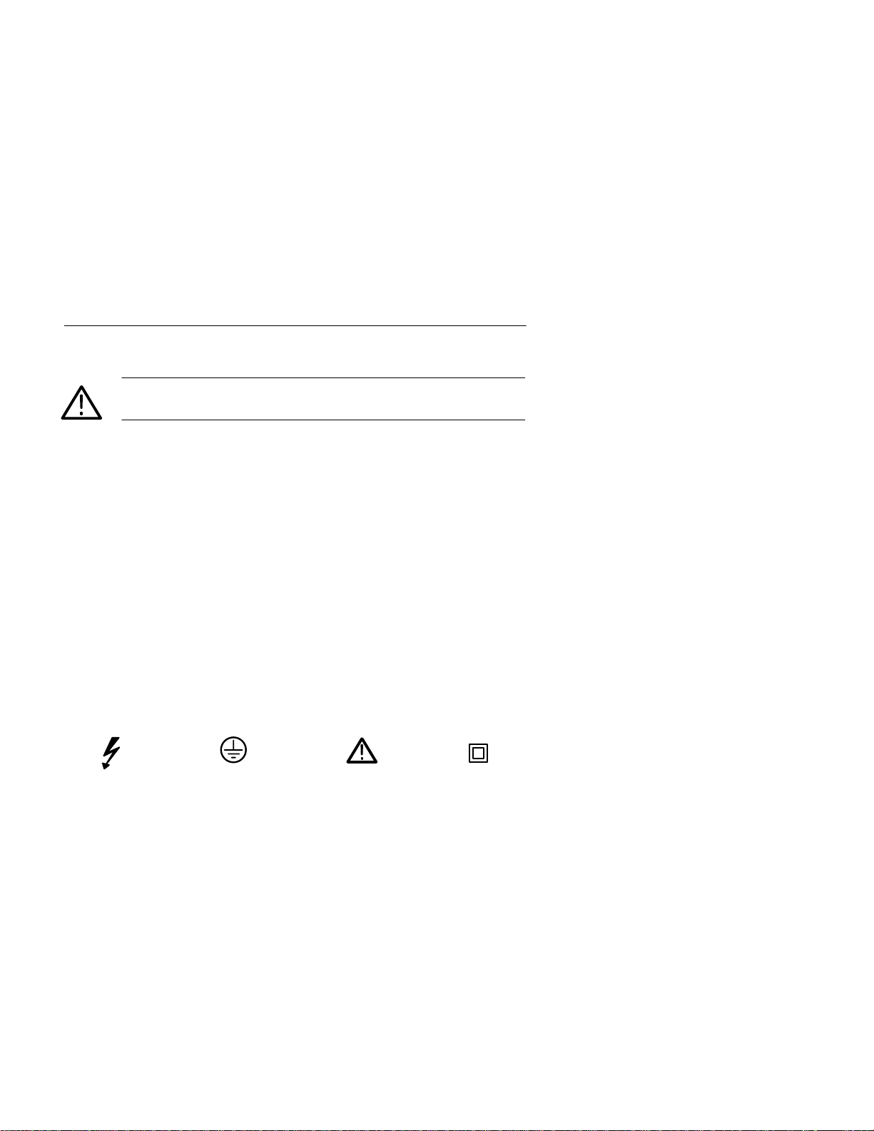
Symbols on the Product
The following symbols may appear on the product:
DANGER
High Voltage
Protective Ground
(Earth) T erminal
Certifications and Compliances
CSA Certified Power Cords
CSA Certification includes the products and power cords appropriate
for use in the North America power network. All other power cords
supplied are approved for the country of use.
CFG280 User Manual
ATTENTION
Refer to
Manual
Double
Insulated
v
Page 10

General Safety Summary
vi
CFG280 User Manual
Page 11

Getting Started
The Tektronix CFG280 Function Generator produces low distortion
sine waves, square waves, triangle waves, TTL sync signals, positive
and negative pulses, and ramp waveforms in a frequency range of
0.1 Hz to 11 MHz. You can also directly control amplitude and
DC offset.
The sweep function makes the output signal traverse a range of
frequencies. The START and ST OP FREQ control settings determine
the sweep rate and sweep width internally or the sweep function can
be input from an external DC signal.
A voltage-controlled frequency (VCF) input controls the output
frequency from an external voltage source. The output frequency can
be swept above or below the selected frequency to a maximum of
100:1, depending on the polarity and amplitude of the VCF input and
the selected output frequency. Provisions are also made for amplitude
modulation of the sine wave output from an external source.
An external gate input allows the generator to operate for the
duration of an externally applied gating signal. This mode provides
either a single cycle output or a train of preselected waveforms,
depending on the gating signal width and the function generator
frequency setting.
The CFG280 Function Generator has a frequency counter to count
the signal frequency of sine, square and triangle waves from 1 Hz to
100 MHz. The frequency counter features one five-digit display with
automatic decimal point placement and LED indicators that show the
display measurement unit and mode. It can measure periods in
seconds or frequencies in kHz or MHz. The front panel controls also
provide selectable gate times (resolution) and selectable X10
attenuation.
The CFG280 has a locking, multiposition handle that folds under the
instrument. The instrument comes with a power cord, an installed
fuse for 115V operation, and this manual.
CFG280 User Manual
1
Page 12
Getting Started
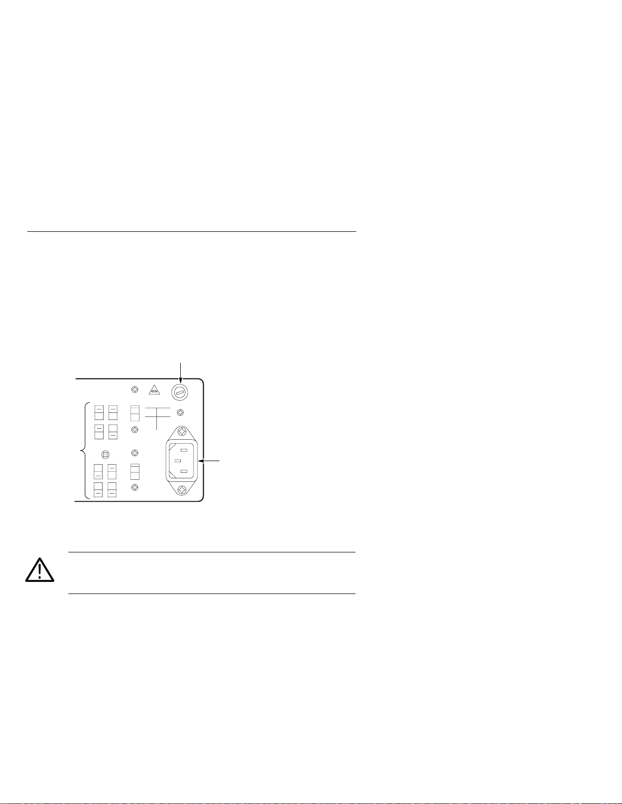
Preparing the Function Generator for Use
Check the following items prior to operating the CFG280 Function
Generator for the first time (see Figure 1 for locations of items 1
through 3):
2
1
3
Figure 1: Line Voltage Selectors, Power Input, and Fuse Locations
CAUTION. To prevent damage to the instrument, set the line voltage
selectors to the proper voltage setting and install the correct line
voltage fuse before operating the equipment.
1. Set the line voltage selectors to the input line voltage. These
selectors connect internal wiring for various line voltages. This
product is intended to operate from a power source that does not
supply more than 250 V
between either supply conductor and ground. For line voltage
ranges, refer to Appendix A: Specifications on page 17.
2
between the supply conductors or
RMS
CFG280 User Manual
Page 13

Getting Started
WARNING. To prevent electrical shock, unplug the power cord and
disconnect the signal cable from any signal source before checking
or replacing the fuse.
2. Check that the correct line fuse is installed. The line fuse
provides protection if the equipment malfunctions or an overload
occurs. Refer to Appendix C: Replaceable Parts on page 29 for
fuse part numbers.
WARNING. To prevent electrical shock, connect the power cord to a
properly grounded power source. The outside (ground) of this
connector is connected through the equipment to the power source
ground. Do not remove the ground lug from the power cord for any
reason.
3. Connect the input power cord. Use only the power cords specified
for this equipment. Refer to Appendix C: Replaceable Parts on
page 29 for power cord part numbers.
CFG280 User Manual
3
Page 14

Getting Started
Front Panel
Figure 2 shows the front-panel controls, connectors, and indicators of
the CFG280 Function Generator.
31 2 456 7 89
141312
15
2425
Figure 2: Front Panel Controls, Connectors, and Indicators
1. OVERRANGE LED. Lights if you apply a frequency above
specified limits to the EXT COUNTER INPUT connector. It also
lights if the gate time is too slow for the incoming signal.
2. GATE LED. Lights when the frequency counter is making a
measurement. The LED will blink when the counter updates the
display .
16
10 11
17
182022 2123 19
3. Counter Readout. This is a five-digit display that shows
frequency counter measurements. The decimal point is
automatically placed in the appropriate position, depending on
the measurement and resolution.
4. MULTIPLIER LEDs. Indicate the frequency multiplication factor
of the function generator outputs. The 10-1M LED indicates a
factor from 10 through 10
the counter readout and FREQUENCY Range LEDs.
4
6
. You should use the 10-1M LED with
CFG280 User Manual
Page 15

Getting Started
The 1 and 0.1 LEDs provide accurate indication for the two
lowest frequency ranges. For example, if the FREQUENCY dial
is set on 2.6 and the 1 LED is lighted, the function generator
output frequency is 2.6 Hz.
5. FREQUENCY Range LEDs. Indicate the range (either MHz or
kHz) of the reading shown on the counter readout. These LEDs
also indicate the frequency range of the function generator
output. For example, if the FREQUENCY dial is set on 9, the
10-1M LED is lighted, the kHz LED is lighted, and the counter
readout shows .090, then the function generator output frequency
is 0.090 kHz = 90 Hz.
NOTE. You must have the SOURCE button set on INT (pushed out) to
2
differentiate between the 10, 10
, 103 (kHz),104,105, and 106 (MHz)
generator output ranges.
6. SEC LED. Lights when the frequency counter is in PERIOD
mode. The counter readout does not show frequency in hertz, but
period in seconds. For example, if the FREQUENCY dial is set at
4, the 1 multiplier LED is lighted, and the SEC LED is lighted,
the counter readout displays a value close to 0.250. This indicates
the generator output period is .25 s (the frequency is 4 Hz).
7. MULTIPLIER Buttons. Set the frequency range. The left button
raises the range by a power of ten and the right button lowers the
range by a power of ten. For example, if the FREQUENCY dial
is set to 4.7 and the output is set to kHz, when you press the left
multiplier button the output frequency will jump from
3
4.7 10
Hz (4.7 kHz) to 4.7 104 Hz (47 kHz).
8. FUNCTION Buttons. Select the type of waveform generated:
sine, triangle, or square.
9. Symmetry Buttons. Select either positive pulse/ramp or negative
pulse/ramp (see T able 1 on page 6). When you push either
button in, the output frequency is 1/10 of the value shown on the
FREQUENCY dial. When you push both buttons in, the output
frequency is 1/19 of the value shown on the FREQUENCY dial.
CFG280 User Manual
5
Page 16

Getting Started
Table 1
Wavefor
Ri
: Effect of Symmetry Buttons on Output
m Left Symmetry Button
10.SWEEP Button. Activates the internal sweep generator, which
produces a signal that traverses a range of frequencies. This
button enables the SWEEP RATE and SWEEP WIDTH knobs.
You can also feed an external sweep signal into the CFG280
Function Generator through a connector on the rear panel. See
External Sweep on page 11 for further details.
11. SWEEP RATE Knob. Adjusts how often the frequency sweep
reiterates—the rate at which the signal traverses the frequencies.
If you pull this button out, the sweep will stop and you can adjust
the sweep stop frequency with the SWEEP WIDTH knob.
12.GATE SEL Button. Selects the gate time. If the gate time is too
slow for the incoming signal, the OVERRANGE LED lights.
ght Symmetry Button
13.ATTN Button. Selects between two levels of input signals for the
EXT COUNTER INPUT. When you push the button in, the
CFG280 Function Generator attenuates the incoming signal by a
factor of ten (the peak-to-peak input level must be between 3 V
and 42V). When you push the button out, the function generator
does not attenuate the input signal (the peak-to-peak input level
must be between 50 mV and 5 V).
6
CFG280 User Manual
Page 17

Getting Started
14.SOURCE Button. Selects between internal and external counter
input. When you push the button in, the counter readout displays
the signal frequency count from the EXT COUNTER INPUT.
When you push the button out the counter readout displays the
frequency count of the signal being generated by the CFG280
Function Generator.
15.MAIN Button. Selects between two voltage ranges: 0 V
2 V
p-p
or 0 V
to 20 V
p-p
. This control is used with the
p-p
p-p
to
AMPLITUDE control to set the voltage level of the MAIN OUT
signal.
16.AMPLITUDE Knob. Adjusts the voltage within the presently
selected range. This control is used with the MAIN control to set
the voltage level of the MAIN OUT signal.
17.DC OFFSET Knob. Sets the DC level (and therefore the polarity)
of the MAIN OUT signal. This knob has no effect until you pull
it out.
18.SWEEP WIDTH Knob. Adjusts the range of frequencies that are
traversed by each sweep.
19.SWEEP OUT BNC. This connector sends sweep signals that you
can adjust with the sweep controls. You can use a sweep signal to
synchronize an external device such as an oscilloscope.
20.MAIN OUT BNC. This connector sends sine, triangle, square,
and positive and negative pulse/ramp signals.
21.SYNC OUT BNC. This connector sends TTL trigger signals.
Amplitude and DC offset adjustments do not affect TTL trigger
output.
22.EXT COUNTER INPUT BNC. This connector can accept
external signals with frequencies between 1 Hz and 100 MHz.
23.FREQ FINE ADJ knob. Allows small adjustments in output
frequency .
24.FREQUENCY Dial. Determines the frequency of the function
generator output, within the range set by the MULTIPLIER
buttons.
25.POWER switch. Toggles instrument power on and off.
CFG280 User Manual
7
Page 18

Getting Started
Rear Panel
In addition to the line voltage switches, fuse, and power cord
receptacle, the items shown in Figure 3 are located on the rear panel.
1
2
3
Figure 3: Rear Panel Connections
CAUTION. To avoid the risk of fire or damage to theCFG280
Function Generator, be sure input equipment is properly grounded
before connecting it to the function generator.
1. GATE INPUT BNC. This connector accepts external gate signals,
which you can use in tone-burst generation. See page 13 for
details.
2. EXT AM INPUT BNC. This connector accepts external
amplitude modulation signals. See page 12 for details.
3. VCF INPUT BNC. This connector accepts external sweep
signals. See page 11 for details.
8
CFG280 User Manual
Page 19

Reference
This section describes several advanced functions of the CFG280
Function Generator. The variety of swept and modulated signals
available from the function generator make it especially useful for
such applications as testing servo-system or amplifier response,
distortion, and stability. It can be used for FM generation, frequency
multiplication, or as a variable, beat-frequency oscillator. It can be
used to generate repetition rates or tone bursts. The square wave sync
and sweep outputs can be used as a source for TTL logic or to
synchronize an external device,such as an oscilloscope. The CFG280
Function Generator is also useful as a source for amplitude
modulated signals for various purposes.
TTL Signals
T o generate a TTL signal, follow these steps:
1. Connect the SYNC OUT connector on the CFG280 Function
Generator to the input BNC connector on an oscilloscope (see
Figure 4) .
Figure 4: TTL Signal Test Setup
2. Observe the results on the oscilloscope. If necessary , change the
volts per division setting or other controls on the oscilloscope to
acquire a useful signal.
CFG280 User Manual
CFG280
Test oscilloscope
9
Page 20

Reference
3. Change the FREQUENCY range and rotate the FREQUENCY
dial. Observe how the frequency of the TTL signal changes.
4. Rotate the DC OFFSET knob. Notice that this knob has no effect
on TTL signals.
The DC OFFSET knob has no effect because the DC offset of a
TTL signal is standardized for compliance with TTL logic.
Signals produced from the SYNC OUT connector are not affected
by this knob.
5. Rotate the AMPLITUDE knob. Notice that this knob has no
effect on TTL signals.
The AMPLITUDE knob has no effect because the amplitude of a
TTL signal is standardized for compliance with TTL logic.
Internal Sweep
T o use the internal sweep function, follow these steps:
1. Connect the MAIN OUT BNC on the CFG280 Function
Generator to the device under test, such as a filter (see Figure 5).
10
2. Connect the SWEEP OUT connector to one channel of an
oscilloscope (see Figure 5).
MAIN OUT
SWEEPOUT
CFG280
Device
under test
Test oscilloscope
Figure 5: Internal Sweep T est Setup
CFG280 User Manual
Page 21

3. Connect another channel of the oscilloscope to the device under
test (see Figure 5).
4. Push the SWEEP button out on the function generator to
deactivate the internal sweep function.
5. Turn the FREQUENCY dial to the desired sweep start frequency
(the lowest point on the sweep).
6. Push the SWEEP button in to enable the internal sweep function.
7. Pull the SWEEP RA TE knob out to lock the function generator
at the sweep stop frequency (the highest point on the sweep).
8. Adjust the sweep stop frequency with the SWEEP WIDTH
knob.
9. Now push the SWEEP button in to activate the internal linear
sweep. Use the SWEEP RA TE knob to adjust the sweep rate.
External Sweep
T o use the external sweep function, follow these steps:
Reference
1. Connect the MAIN OUT connector on the CFG280 Function
Generator to the oscilloscope input connector (see Figure 6).
Test oscilloscope
Figure 6: External Sweep T est Setup
CFG280 User Manual
To VCF INPUT
(on rear panel)
Voltage source
CFC280
MAIN OUT
11
Page 22

Reference
2. Turn the Frequency Dial to the 0.1 position.
CAUTION. To avoid damage to the CFG280, ensure that the maximum
voltage into the rear panel VCF INPUT is no more than ±10 V pk.
3. Connect an external voltage signal to the VCF INPUT on the
rear panel of the instrument (see Figure 6).
4. Push the SWEEP button out to deactivate the internal sweep
function.
When using an external sweep signal, the SWEEP WIDTH and
SWEEP RATE knobs have no effect on the signal sweep. Instead,
these parameters are controlled entirely by the external signal
provided through the rear panel.
Amplitude Modulation
T o use the amplitude modulation function, follow these steps.
1. Connect the MAIN OUT connector on the CFG280 Function
Generator to the oscilloscope input (see Figure 7).
To EXT AM INPUT
(on rear panel)
Test oscilloscope
Figure 7: Amplitude Modulation T est Setup
12
Voltage source
CFG280
MAIN OUT
CFG280 User Manual
Page 23

2. Push the sine wave FUNCTION button.
3. Set the FREQUENCY dial to the desired carrier frequency.
CAUTION. To avoid damage to theCFG280 Function Generator,
ensure that the maximum voltage into the rear panel VCF INPUT is
no more than 5 V
4. Connect an external voltage signal to the EXT AM INPUT on
the rear panel of the instrument (see Figure 7).
5. Control the amplitude modulation by varying the voltage level of
the external voltage source.
p-p
.
Tone-Burst Generation and Stepped Frequency Multiplication
You can use the CFG280 Function Generator as a tone-burst
generator or frequency multiplier for checking tone-controlled
devices. This application requires another function generator (such as
the T ektronix CFG253) to serve as a gating signal source and a ramp
generator to serve as a VCF signal source.
Reference
1. Connect the MAIN OUT connector on the CFG280 Function
Generator to the oscilloscope input connector (see Figure 8).
2. Connect the ramp generator output to the VCF INPUT connector
on the rear of the CFG280 Function Generator (see Figure 8).
CFG280 User Manual
13
Page 24

Reference
Test oscilloscope
CFG253
To VCF INPUT (on rear panel)
To GATE INPUT (on rear panel)
CFG280
Ramp
Generator
MAIN OUT
EXT
IN
Figure 8: Tone-Burst and Stepped Frequency Multiplication Test Setup
3. Connect the MAIN OUTPUT of the CFG253 to a BNC T
connector. Connect the BNC T outputs to the GATE INPUT
connector on the CFG280 Function Generator and the external
input on the ramp generator (see Figure 8).
4. Set the ramp generator to generate the desired ramp duration and
polarity.
5. Adjust the CFG253 Function Generator output period to the
desired number of bursts within the selected ramp duration.
6. Adjust the CFG253 Function Generator output duration to the
desired burst width.
RAMP
OUT
14
CFG280 User Manual
Page 25

VCF input
GATE input
Tone-Burst or stepped
frequency output
Figure 9: Tone-Burst and Stepped Frequency Typical Waveforms
7. Select the sweep frequency range by adjusting the
FREQUENCY dial to one end of the swept range (upper or
lower limit, depending on the polarity of the ramp) and adjusting
the other end with the RG501 output amplitude.
Reference
CFG280 User Manual
15
Page 26

Reference
16
CFG280 User Manual
Page 27

Appendix A: Specifications
T ables 2 through 5 show characteristics of the CFG280 Function
Generator that are guaranteed by warranty.
Table 2: Generator Specifications
Characteristic
Outputs Square wave, sine wave, triangle wave, TTL
Frequency Ranges 0.1 Hz to 11 MHz, up/down range switchable in
Dial Range 1 to 11 calibrated
Dial Accuracy ±5% of full scale from 0.1 Hz to 10 MHz
Pulse and Ramp Frequency 1/10 of dial frequency
Pulse and Ramp Aspect
Ratio
Main Output Amplitude Two ranges:
Measurement
pulse, positive and negative ramp, pulse and
skewed sine wave, AM, and sweep functions
eight decade steps
0.1 to 1 uncalibrated
11 MHz setting not less than 11 MHz
(ambient temperature 20
95:5
0–20 V
p–p
200 mV to 20V
100 mV to 10V
0–0.2 V
p–p
20 mV to 2V
10 mV to 1V
_ C to 30_ C)
(open circuit)
p-p
(50 load)
p-p
(open circuit)
p-p
(50 load)
p-p
Main Output Impedance
DC Offset <–10 V to >+10V (open circuit)
50 ±10%
<–5 V to >+5V (into 50
load)
CFG280 User Manual
17
Page 28

Appendix A: Specifications
Amplitude Flatness
Withi
S
<25 ns into 50loa
External Gate I
t
gate signal require
Amplitude Modulatio
ith 5
200 kH
Table 2: Generator Specifications (Cont.)
Characteristic Measurement
n ±0.5 dB, 0.1 Hz to 110 kHz
(At 10 kHz, 50 Load)
Sine Wave Distortion <1% from 10 Hz to 100kHz
Within ±1.5 dB, to 1.1 MHz
Within ±2.5 dB, to 11 MHz
–30 dB at all other frequencies
(ambient temperature 20
_ C to 30_ C)
Triangle Wave Linearity
Square Wave Transition
Time
Square Wave Aberrations 4% peak-to-peak at maximum output into a
ync TTL Output
Rise/Fall Time
VCF (FM) Input A ±10 V signal input shifts frequency 1000:1 up or
npu
Internal Sweep Rate Continuously variable from 0.5 to 50Hz
Internal Sweep Width Variable from 1:1 to 100:1
n 100% w
0.1 Hz to 100Hz 99%
100 kHz to 1MHz 97%
Measured from 10% to 90% of waveform
25 ns rise/fall time at maximum output into a
load
50
load
50
d
down with dial set at 0.1 or 11 respectively
+2 V
fixed 0 degree start phase
V
DSB suppressed carrier modulation is also
obtained by input modulating the signal with
+2.5 VDC offset
Input impedance = 3 k
p-p
d, not to exceed +15 V
, DC to
z
18
CFG280 User Manual
Page 29

Table 3: Counter Specifications
I
Selectio
Internal a
selectable
Freque
ge
DC to 100 MH
al
Resolutio
Freque
A
Freque
time base erro
Appendix A: Specifications
Characteristic
nput
ncy Ran
n
Measurement
nd external input
z for intern
1 Hz to 100 MHz, AC coupled for external
n
ncy mode: 1 Hz, 10 Hz, 1 kHz
Period mode: 1 ms
ccuracy
ncy mode: ±(1 count +
Period mode: ±(1 count + time base error
+ trigger error)
External Input
Sensitivity
Impedance
1 Hz to 50 MHz
50 MHz to 100 MHz
1 M paralleled by 40 pF
Attenuation 3 V to 42 V (X10)
50 mV to 5 V (X1)
Maximum Input Voltage 42 V peak
Internal Time Base
r)
Crystal Frequency 10 MHz
Temperature Stability
<0.001% (10 ppm from 0_C to 40_C)
Line Voltage Stability <±1 ppm with 10% line voltage variation
Aging Rate <±10 ppm/yr
CFG280 User Manual
19
Page 30

Appendix A: Specifications
Table 4: General Specifications
Characteristic
Line Voltage Range Selectable ranges at 50 Hz to 60 Hz
Operating Temperature
Nonoperating Temperature
Measurement
90 VAC to 110 VAC
108 VAC to 132 VAC
198 VAC to 242 VAC
216 VAC to 250 VAC
+0_C to +40_C, 80% relative humidity
–10_C to +70_C, 70% relative humidity
Table 5: Certifications and Compliances
EC Declaration of
Conformity – EMC
EC Declaration of
Conformity – Low
Voltage
Meets intent of Directive 89/336/EEC for Electromagnetic
Compatibility. Compliance was demonstrated to the following
specifications as listed in the Official Journal of the European
Communities:
EN 55011 Class A Radiated and Conducted Emissions
EN 50081-1 Emissions:
EN 60555-2 AC Power Line Harmonic Emissions
EN 50082-1 Immunity:
IEC 801-2 Electrostatic Discharge Immunity
IEC 801-3 RF Electromagnetic Field Immunity
IEC 801-4 Electrical Fast Transient/Burst Immunity
IEC 801-5 Power Line Surge Immunity
Compliance was demonstrated to the following specification as
listed in the Official Journal of the European Communities:
Low Voltage Directive 73/23/EEC, amended by 93/68/EEC.
20
HD401 S1 Safety Requirements for Electronic
Measuring Aparatus.
CFG280 User Manual
Page 31

Table 6: Typical Mechanical Specifications
Appendix A: Specifications
Characteristic
Dimensions
(H x W x D)
Weight 3.0 kg (6.6 lb)
Measurement
100 mm X 240 mm X 230 mm
(3.9 in x 9.5 in x 9.0 in)
CFG280 User Manual
21
Page 32

Appendix A: Specifications
22
CFG280 User Manual
Page 33

Appendix B: Maintenance
This appendix provides information for the basic maintenance of the
CFG280 Function Generator.
Cleaning
T o clean the CFG280 Function Generator, use a soft cloth dampened
in a solution of mild detergent and water. Do not spray cleaner
directly onto the instrument, since it may leak into the cabinet and
cause damage.
Do not use chemicals containing benzine, benzene, toluene, xylene,
acetone, or similar solvents.
Do not use abrasive cleaners on any portion of the function
generator.
Preparing for Shipment
If the original packaging is unfit for use or not available, use the
following packaging guidelines:
1. Use a corrugated cardboard shipping carton having inside
dimensions at least three inches greater than the instrument
dimensions.
2. Put the instrument into a plastic bag or wrap to protect it from
dampness and loose packing material.
3. Place the instrument into the box and firmly stabilize it with
packing material.
4. Seal the carton with shipping tape.
CFG280 User Manual
23
Page 34

Appendix B: Maintenance
Troubleshooting
Use the following diagrams to identify basic problems with your
instrument setup. The diagrams do not provide instructions for or
recommend instrument disassembly. If these diagrams fail to solve
your problem, send your instrument to the nearest T ektronix service
center.
NOTE. These diagrams assume that any other test equipment you use
is operating properly. Before you assume a problem exists with
theCFG280 Function Generator, check all other test equipment.
Start.
Digital Display Blank
Are
any LEDs
lighted?
No
Is
power cord
firmly connected to both
instrument and power
source?
No
Ensure good
power cord
connection at
both ends.
Yes
Send your
instrument to the
nearest T ektronix
service center.
Yes
instrument line
voltage setting
fuse appropriate
for current line voltage and
operational?
instrument to the
nearest T ektronix
service center.
Is
correct?
Yes
Is the
Yes
Send your
No
No
Adjust with rear
panel switches.
Replace with
proper fuse (see
Selecting the
Fuse).
24
CFG280 User Manual
Page 35

Start.
Is the
digital display
frozen?
Yes
Inappropriate Counter Reading
Are
No
function, gate,
and attenuation
settings appropriate for the
input
signal?
Yes
Send your instrument to
the nearest T ektronix
service center.
Appendix B: Maintenance
No
Change settings to
accommodate the
input signal.
Are
you using the
external input
connector?
Yes
Check connection and
voltage level of signal.
No
T oggle the
SOURCE button.
CFG280 User Manual
25
Page 36

Appendix B: Maintenance
No Function Generator Output
Start.
Is the
digital display
blank?
No
Does
oscilloscope have good
connection to output jack?
Yes
Are
amplitude settings too
low to produce visible
signal?
No
Are
range and function
selected?
Yes
Send your instrument to the
nearest T ektronix service
center.
Yes
No
No
Yes
Go to
Digital Display
Blank on page
24.
Ensure good
electrical
connection to
output jack.
Adjust with
AMPLITUDE
knob and MAIN
button.
Push appropriate
MULTIPLIER and
FUNCTION
buttons.
26
CFG280 User Manual
Page 37

Start.
Appendix B: Maintenance
Inappropriate Function Generator Output
Is signal
amplitude too
large or too
small?
No
Is signal
frequency too fast
or slow?
No
Is signal responsive to
sweep rate and sweep
width adjustments?
Yes
Is signal
responsive to DC
offset
adjustments?
Yes
Adjust with AMPLITUDE knob and MAIN
Yes
Adjust with MULTIPLIER
buttons and FREQUENCY dial.
No
you using internal or
Sweep knobs do not
function in external
sweep mode.
No
DC OFFSET knob
pulled out?
Are
external
sweep?
Is
button.
External
Internal
Pull DC OFFSET knob
No
out to activate DC offset
Push in SWEEP
button to activate
internal sweep.
No
Is
SWEEP button
pushed
in?
Yes
Send your
instrument to the
nearest T ektronix
service center.
function.
Done.
CFG280 User Manual
Yes
Send your instrument to the
nearest T ektronix service
center.
27
Page 38

Appendix B: Maintenance
28
CFG280 User Manual
Page 39

Appendix C: Replaceable Parts
Replaceable parts may be ordered directly from your authorized
T ektronix dealer.
Standard Accessories
The following items are shipped with the CFG280 Function
Generator:
Table 7: Standard Accessories
Accessory
Fuse, 3AG, 0.6 A, 250 V, SB
(90 – 132 V operation)
CFG280 User Manual 070–8559–XX
115 V Power Cord Refer to Table 9
Optional Accessories
The following items are available as optional accessories:
Table 8: Optional Accessories
Accessory
Fuse, 3AG, 0.3 A, 250 V, SB
(198 – 250 V operation)
230 V Power Cords Refer to Table 9
36-inch, 50 W BNC cable
66-inch, 50ĂW coaxial cable signal
adapter
Tektronix Part Number
159–0043–00
Tektronix Part Number
159–0029–00
012–1341–XX
103–0275–XX
CFG280 User Manual
29
Page 40

Appendix C: Replaceable Parts
The following power cords are available.
Table 9: Accessory Power Cords
Plug Configuration
Normal Usage
North America
115 V
Tektronix Part
Number
161-0104-00
Europe
230 V
United Kingdom
230 V
Australia
230 V
North America
230 V
Switzerland
230 V
161-0104-06
161-0104-07
161-0104-05
161-0104-08
161-0167-00
30
CFG280 User Manual
 Loading...