

Page 1

User Manual
CDM250
Digital Multimeter
070-6736-03
Page 2

Copyright T ektronix, Inc. 1987. All rights reserved.
T ektronix products are covered by U.S. and foreign patents, issued and
pending. Information in this publication supercedes that in all previously
published material. Specifications and price change privileges reserved.
T ektronix, Inc., P.O. Box 1000, Wilsonville, OR 97070–1000
TEKTRONIX and TEK are registered trademarks of T ektronix, Inc.
Page 3

WARRANTY
Tektronix warrants that this product will be free from defects in materials and
workmanship for a period of one (1) year from the date of shipment. If any such product
proves defective during this warranty period, Tektronix, at its option, either will repair the
defective product without charge for parts and labor, or will provide a replacement in
exchange for the defective product.
In order to obtain service under this warranty, Customer must notify Tektronix of the defect
before the expiration of the warranty period and make suitable arrangements for the
performance of service. Customer shall be responsible for packaging and shipping the
defective product to the service center designated by Tektronix, with shipping charges
prepaid. Tektronix shall pay for the return of the product to Customer if the shipment is to
a location within the country in which the Tektronix service center is located. Customer
shall be responsible for paying all shipping charges, duties, taxes, and any other charges for
products returned to any other locations.
This warranty shall not apply to any defect, failure or damage caused by improper use or
improper or inadequate maintenance and care. Tektronix shall not be obligated to furnish
service under this warranty a) to repair damage resulting from attempts by personnel other
than Tektronix representatives to install, repair or service the product; b) to repair damage
resulting from improper use or connection to incompatible equipment; or c) to service a
product that has been modified or integrated with other products when the effect of such
modification or integration increases the time or difficulty of servicing the product.
THIS WARRANTY IS GIVEN BY TEKTRONIX WITH RESPECT TO THIS
PRODUCT IN LIEU OF ANY OTHER WARRANTIES, EXPRESSED OR
IMPLIED. TEKTRONIX AND ITS VENDORS DISCLAIM ANY IMPLIED
WARRANTIES OF MERCHANTABILITY OR FITNESS FOR A PARTICULAR
PURPOSE. TEKTRONIX’ RESPONSIBILITY TO REPAIR OR REPLACE
DEFECTIVE PRODUCTS IS THE SOLE AND EXCLUSIVE REMEDY
PROVIDED TO THE CUSTOMER FOR BREACH OF THIS WARRANTY.
TEKTRONIX AND ITS VENDORS WILL NOT BE LIABLE FOR ANY
INDIRECT, SPECIAL, INCIDENTAL, OR CONSEQUENTIAL DAMAGES
IRRESPECTIVE OF WHETHER TEKTRONIX OR THE VENDOR HAS
ADVANCE NOTICE OF THE POSSIBILITY OF SUCH DAMAGES.
Page 4

Page 5

Table of Contents
General Safety Summary iii. . . . . . . . . . . . . . . . . . . . . . . . . . . .
Getting Started 1. . . . . . . . . . . . . . . . . . . . . . . . . . . . . . . . . . . . .
Preparing the Digital Multimeter for Use 2. . . . . . . . . . . . . . . . .
Front Panel 4. . . . . . . . . . . . . . . . . . . . . . . . . . . . . . . . . . . . . . . . .
Reference 7. . . . . . . . . . . . . . . . . . . . . . . . . . . . . . . . . . . . . . . . .
Preparations for Measurement 7. . . . . . . . . . . . . . . . . . . . . . . . . .
Measuring AC or DC Voltage 7. . . . . . . . . . . . . . . . . . . . . . . . . .
Measuring AC or DC Current 8. . . . . . . . . . . . . . . . . . . . . . . . . .
Measuring Resistance 9. . . . . . . . . . . . . . . . . . . . . . . . . . . . . . . .
Checking Diodes 10. . . . . . . . . . . . . . . . . . . . . . . . . . . . . . . . . . . .
Appendix A: Specifications 11. . . . . . . . . . . . . . . . . . . . . . . . . . .
Appendix B: Maintenance 17. . . . . . . . . . . . . . . . . . . . . . . . . . .
Cleaning 17. . . . . . . . . . . . . . . . . . . . . . . . . . . . . . . . . . . . . . . . . . .
Preparing for Shipment 17. . . . . . . . . . . . . . . . . . . . . . . . . . . . . . .
Troubleshooting 18. . . . . . . . . . . . . . . . . . . . . . . . . . . . . . . . . . . . .
No Display with Power On 18. . . . . . . . . . . . . . . . . . . . . . . . .
CDM250 Does Not Read Current (2A) 18. . . . . . . . . . . . . . . .
Display On but CDM250 Not Displaying Reading 18. . . . . . .
Display On but CDM250 Does Not Read Current (10A) 19. .
Appendix C: Replaceable Parts 21. . . . . . . . . . . . . . . . . . . . . . .
Standard Accessories 21. . . . . . . . . . . . . . . . . . . . . . . . . . . . . . . . .
Optional Accessories 21. . . . . . . . . . . . . . . . . . . . . . . . . . . . . . . . .
CDM250 User Manual
i
Page 6

T able of Contents
List of Tables
T able 1: General Characteristics 11. . . . . . . . . . . . . . . . . . . . . . . .
T able 2: Physical Characteristics 11. . . . . . . . . . . . . . . . . . . . . . .
T able 3: Environmental Characteristics 11. . . . . . . . . . . . . . . . . .
T able 4: Electrical Characteristics 12. . . . . . . . . . . . . . . . . . . . . .
T able 5: DC Volts Measurement Specifications 12. . . . . . . . . . . .
T able 6: AC Volts Measurement Specifications 13. . . . . . . . . . . .
T able 7: Direct Current Measurement Specifications 13. . . . . . . .
T able 8: Alternating Current Measurement Specifications 15. . . .
T able 9: Resistance Measurement Specifications 16. . . . . . . . . . .
T able 10: Standard Accessories 21. . . . . . . . . . . . . . . . . . . . . . . .
T able 11: Optional Accessories 21. . . . . . . . . . . . . . . . . . . . . . . .
T able 12: Accessory Power Cords 22. . . . . . . . . . . . . . . . . . . . . .
ii
CDM250 User Manual
Page 7

General Safety Summary
Review the following safety precautions to avoid injury and prevent
damage to this product or any products connected to it.
Injury Precautions
T o avoid potential hazards, use the product only as specified.
Use Proper Power Cord
T o avoid fire hazard, use only the power cord specified for this
product.
Avoid Electric Overload
T o avoid electric shock or fire hazard, do not apply a voltage to a
terminal that is outside the range specified for that terminal.
Ground the Product
This product is grounded through the grounding conductor of the
power cord. T o avoid electric shock, the grounding conductor must
be connected to earth ground. Before making connections to the
input or output terminals of the product, ensure that the product is
properly grounded.
Do Not Operate Without Covers
T o avoid electric shock or fire hazard, do not operate this product
with covers or panels removed.
Use Proper Fuse
T o avoid fire hazard, use only the fuse type and rating specified for
this product.
CDM250 User Manual
iii
Page 8

General Safety Summary
Do Not Operate in Wet/Damp Conditions
T o avoid electric shock, do not operate this product in wet or damp
conditions.
Do Not Operate in Explosive Atmosphere
T o avoid injury or fire hazard, do not operate this product in an
explosive atmosphere.
Product Damage Precautions
Use Proper V oltage Setting
Before applying power, ensure that the line selector is in the proper
position for the power source being used.
Provide Proper Ventilation
T o prevent product overheating, provide proper ventilation.
Do Not Operate With Suspected Failures
If you suspect there is damage to this product, have it inspected by
qualified service personnel.
Safety Terms and Symbols
Terms in This Manual
These terms may appear in this manual:
WARNING. Warning statements identify conditions or practices that
could result in injury or loss of life.
iv
CDM250 User Manual
Page 9

General Safety Summary
CAUTION. Caution statements identify conditions or practices that
could result in damage to this product or other property.
Terms on the Product
These terms may appear on the product:
DANGER indicates an injury hazard immediately accessible as you
read the marking.
WARNING indicates an injury hazard not immediately accessible as
you read the marking.
CAUTION indicates a hazard to property including the product.
Symbols on the Product
The following symbols may appear on the product:
DANGER
High Voltage
Protective Ground
(Earth) T erminal
Certifications and Compliances
CSA Certified Power Cords
CSA Certification includes the products and power cords appropriate
for use in the North America power network. All other power cords
supplied are approved for the country of use.
CDM250 User Manual
ATTENTION
Refer to
Manual
Double
Insulated
v
Page 10

General Safety Summary
vi
CDM250 User Manual
Page 11

Getting Started
The Tektronix CDM250 Digital Multimeter measures analog
quantities and displays them in digital form. The CDM250 takes the
following measurements:
H Direct and alternating current from 0 A to 10 A in six ranges
H AC and DC voltage from 200 mV to 500 V in five ranges
H Resistance from 0 to 20 M in six ranges
All values are displayed on a 3
indicator. Alternating voltages and currents are displayed in RMS
values.
The Tektronix CDM250 has a locking, multiposition handle that
folds under the instrument to allow stacking with other instruments
of the same series. The CDM250 is delivered with a set of test leads,
a 115 V power cord, an installed line fuse for 115 V operation, and
this manual.
1
/2 digit, light-emitting diode (LED)
CDM250 User Manual
1
Page 12
Getting Started
Preparing the Digital Multimeter for Use
Check the following items prior to operating the CDM250 Digital
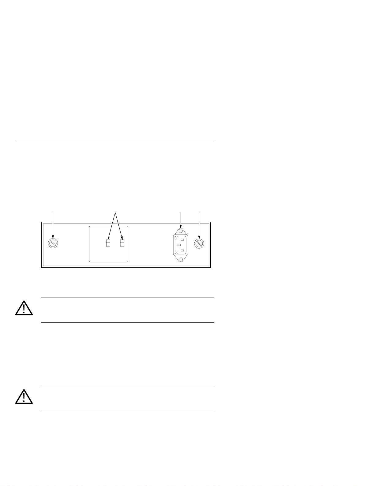
Multimeter for the first time (see Figure 1 for locations of items):
3
Figure 1: Line Voltage Selectors, Power Input, and Fuse Locations
CAUTION. To prevent damage to the instrument, set the line voltage
selectors to the proper voltage setting and install the correct line
voltage fuse before operating the equipment.
1. Set the line voltage selectors to the input line voltage. These
selectors connect internal wiring for various line voltages. This
product is intended to operate from a power source that does not
supply more than 250 V
between either supply conductor and ground. For line voltage
ranges, refer to Appendix A: Specifications on page 11.
1 24
between the supply conductors or
RMS
WARNING. To prevent electrical shock, unplug the power cord and
disconnect the test leads from any voltage source before checking or
replacing the fuses.
2. Check that the correct line fuse is installed. The line fuse
provides protection if the equipment malfunctions or an overload
occurs. Refer to Appendix C: Replaceable Parts on page 21 for
fuse part numbers.
2
CDM250 User Manual
Page 13

Getting Started
3. Check that the correct function fuse is installed. The function
fuse provides protection when using the the 2 A input jacks.
Refer to Appendix C: Replaceable Parts on page 21 for fuse
part number.
WARNING. To prevent electrical shock, connect the power cord to a
properly grounded power source. The outside (ground) of this
connector is connected through the equipment to the power source
ground. Do not remove the ground lug from the power cord for
any reason.
4. Connect the input power cord. Use only power cords that are
equipped with a third conductor that provide a safety ground
connection. Use only the power cords specified for this
equipment. Refer to Appendix C: Replaceable Parts on page 21
for power cord part numbers.
CDM250 User Manual
3
Page 14

Getting Started
Front Panel
Figure 2 shows the front-panel controls, connectors, and indicators
with brief descriptions of the items following the figure.
15234
6789
Figure 2: Front Panel
1. POWER button. Powers the CDM250 on or off. Power ON is
indicated by the LED display.
2. 10 A UNFUSED jack. Input connector for positive (red) test lead
when instrument is used to measure high current (over 2 A but
less than 10 A).
3. V–. Input connector for positive (red) test lead. Used for
AC volts, DC volts, and ohms () functions.
4. LED Display. Shows voltage, current, or resistance value.
Display shows the number 1 at the extreme left in an overrange
condition. Negative voltages or currents are indicated automatically with a minus (–) sign at the extreme left of the display.
5. RANGE buttons. Push to select the highest value of the voltage,
current, or resistance to be measured.
4
CDM250 User Manual
Page 15

Getting Started
6. FUNCTION buttons. Push in only one button to select VOLTS
(voltage), A (current), or (resistance). Only one function will
work at a time.
7. AC/DC button. Push in to measure alternating current or AC
voltage; reset to the out position for direct current or DC voltage.
The AC/DC button may be in either position when the meter is
used for checking resistance.
8. COM jack. Input connector for common (black) test lead. Used
for AC or DC volts, ohms, and current functions. This connector
is not connected to the power source ground through the
instrument.
9. 2 A jack. Input connector for positive (red) test lead when
instrument is used to measure current values up to 2 A.
CDM250 User Manual
5
Page 16

Getting Started
6
CDM250 User Manual
Page 17

Reference
This section of the manual explains how to take the following
measurements:
H AC or DC voltage
H AC or DC current
H Resistance
It also explains how use the CDM250 Digital Multimeter to check
diodes.
Preparations for Measurement
1. Be sure that the CDM250 Digital Multimeter is connected to a
specified power source and that the LINE VOLTAGE SELECTORs are set to the proper position. Refer to Preparing the
Digital Multimeter for Use on page 2.
2. Check that the FUNCTION and RANGE buttons are in the
correct position. If the value to be measured is unknown, start at
the highest range.
3. Be sure the red test lead is in the proper input jack for the
measurement to be made.
Measuring AC or DC Voltage
1. Connect the black test lead to the black COM jack.
2. Connect the red test lead to the red V- jack.
3. For DC voltage, set the AC/DC function button to the out
position. For AC voltage set the AC/DC function switch to the in
position.
4. Push the VOLTS function button in to lock it.
CDM250 User Manual
7
Page 18

Reference
5. Determine the highest anticipated voltage, and push in the
corresponding range button. When the voltage is unknown, select
the highest range.
6. Push the POWER button to the ON position.
NOTE. Voltage readings are taken in parallel with the component or
device being measured.
7. Connect the test leads, and read the displayed value.
NOTE. Remove the red test lead from the circuit or component being
tested before changing ranges.
Measuring AC or DC Current
1. Connect the black test lead to the black COM jack.
2. For current up to 2 A, connect the red test lead to the white 2A
jack. For current between 2 A and 10 A, connect the red test lead
to the white 10A UNFUSED jack.
CAUTION. The 10 A UNFUSED jack is not protected. Excess current
may damage the instrument.
3. T o measure alternating current (AC), set the AC/DC button to the
in position. T o measure direct current (DC), set the AC/DC
button to the out position.
4. Push the A (amperes) button in.
5. Determine the highest anticipated current, and push in the
corresponding range button. When the current value is unknown,
start at the highest range.
8
CDM250 User Manual
Page 19

NOTE. Current readings are taken in series with the component or
device being measured.
6. Push the POWER button to the ON position.
7. Connect the test leads, and read the display value.
NOTE. Remove the red test lead from the circuit or component being
tested before changing ranges.
Measuring Resistance
1. Connect the black test lead to the black COM jack.
2. Connect the red test lead to the red V- jack.
3. Push the (ohms) function button.
4. Determine the highest anticipated resistance on the range scale,
and press the corresponding range button.
Reference
CAUTION. To prevent damage to the equipment, turn off all power to
the circuit or component being measured.
5. Push the POWER button to the ON position.
6. Connect the test leads, and read the display value.
NOTE. When the component being tested is in a circuit where parallel
current paths offer low resistance, the above test may require
disconnecting one end of the component from the circuit.
CDM250 User Manual
9
Page 20

Reference
Checking Diodes
1. Connect the black test lead to the black COM jack.
2. Connect the red test lead to the red V- jack.
3. Push in the (ohms) function button.
4. Simultaneously push the 200 and the 2K range buttons to the in
position.
CAUTION. To prevent damage to the equipment, turn off all power to
the circuit or component being measured.
5. Connect the red test lead to the anode and the black test lead to
the cathode of the diode.
6. Push the POWER button to the ON position. A reading of about
25.0 to 90.0 should appear on the display. Multiply the result by
10 to arrive at the forward voltage drop in millivolts. If the
reading on the display is 1 (overrange indicator), the diode may
be defective (open). If the reading is 00.0, the diode is defective
(shorted).
10
7. Connect the black test lead to the anode and the red test lead to
the cathode of the diode. A reading of 1 (overrange indicator)
should appear on the display. If any other value is displayed, the
diode is defective. On some diodes the meter might flash a high
number for a very short period of time, but the reading should go
to the overrange indicator.
NOTE. When the diode being tested is in a circuit where parallel
current paths offer low resistance, the above tests may require
disconnecting one end of the component from the circuit.
CDM250 User Manual
Page 21

Appendix A: Specifications
Table 1: General Characteristics
Display 31/
Measurements AC and DC voltages, AC and DC currents, and resistance
Maximum Common Mode
Voltage
Zero Adjustment Automatic
Sampling Rate 2.5 measurements per second, nominal
digit LED displays to ±1999 counts, positive polarity
2
assumed, minus (–) sign for negative polarity and the
number 1 at the extreme left as the over range indicator
500 V (DC + AC peak)
Table 2: Physical Characteristics
Width 240 mm (9.4 in)
Height 64 mm (2.5 in)
Depth 230 mm (9.0 in)
Weight 1.8 kg (4.0 lb)
Table 3: Environmental Characteristics
Storage Temperature
Operating Temp
–10_ C to 60_ C, 80% RH
+10_ C to 40_ C, 0 to 75% RH
CDM250 User Manual
11
Page 22

Appendix A: Specifications
Table 4: Electrical Characteristics
Line Voltage Range 90 to 110, 108 to 132, 198 to 242, and 216 to 250 VAC at
50–60 Hz
Power Consumption 10 VA, 6 W maximum
Ground Isolation Maximum of 500 V from earth ground
NOTE. Accuracy is specified for a temperature range of 18_C to
28_C, 75 % RH.
Table 5: DC Volts Measurement Specifications
Range
200 mV
2 V 1 mV
20 V 10 mV
200 V 100 mV
500 V 1 V
Response Time 3 s
Overload Protection 200 mV range: 500 VDC, 350VAC
Resolution Accuracy Input Impedance
100 V
±(0.5% of rdg
+ 1 digit)
2 V to 500 V ranges: 500 VDC, 500 VAC
10 M
12
CDM250 User Manual
Page 23

Appendix A: Specifications
g
igits
4
1og
maximum
1og
maximum
Table 6: AC Volts Measurement Specifications
Manual Ranging
Average responding, calibrated to read RMS value of sine wave
Range Resolution Accuracy Input Impedance
200 mV
2 V 1 mV
20 V 10 mV
200 V 100 mV
500 V 1 V
Response Time 8 s
Overload Protection 200 mV range: 500 VDC, 350VAC
100 V
±(1.0% of rd
+ 4 d
2 V to 500 V ranges: 500 VDC, 500 VAC
)
5–500 Hz
10 M 100 pF
Table 7: Direct Current Measurement Specifications
Manual Ranging
Loading
Range Resolution Accuracy
200 A 0.1 A
2 mA
20 mA
200 mA
2000 mA 1 mA
10 A 10 mA
Response Time 3 s
Overload Protection 2 A range: 2 A, 250 V, fast-blow fuse
1 A
10 A 10
100 A 1
±(1.0% of rdg
+ 1 digit)
±(1.0% of rdg
+ 3 digits)
10 A range: None
Error
300 mV
1.1 V
CDM250 User Manual
Input
Impedance
1 k
100
0.1
.01
13
Page 24

Appendix A: Specifications
g
3
igits
maximum
4
1.1
maximum
Table 8: Alternating Current Measurement Specifications
Manual Ranging
Range Resolution Accuracy Loading Error
200 A 0.1 A
2 mA
20 mA
200 mA
2000 mA 1 mA
10 A 10 mA
Response Time 8 s
Overload Protection 2 A range: 2 A, 250 V, fast-blow fuse
1 A
10 A
100 A
±(1.5% of rd
+ 4 d
10 A range: None
)
5–500 Hz
00 mV RMS
V RMS
14
CDM250 User Manual
Page 25

Table 9: Resistance Measurement Specifications
g
igit
Manual Ranging
Maximum
Range Resolution Accuracy
200 W 0.1 W
2 kW 1 W
20 kW 10 W
200 kW 100 W 5 mA
2000 kW 1 kW
20 MW 10 kW
Response Time
Overload Protection 500 VDC or AC
±(0.75% of rdg
+ 4 digits)
±(0.75% of rd
+ 1 d
)
±(1.5% of rdg
+ 5 digits)
200 W to 2000 kW ranges
20 MW range
Test Current
2.5 mA 3.2 V
250 mA
50 mA
500 nA
50 nA
Appendix A: Specifications
Max. Open
Circuit
Voltage
.6 V
5 s
15 s
CDM250 User Manual
15
Page 26

Appendix A: Specifications
Table 10: Certifications and compliances
EC Declaration of
Conformity
Meets intent of Directive 89/336/EEC for Electromagnetic
Compatibility. Compliance was demonstrated to the
following specifications as listed in the Official Journal of the
European Communities:
EN 55011 Class B Radiated and Conducted
Emissions
EN 50081-1 Emissions:
EN 60555-2 AC Power Line Harmonic Emissions
EN 50082-1 Immunity:
IEC 801-2 Electrostatic Discharge Immunity
IEC 801-3 RF Electromagnetic Field Immunity
1
IEC 801-4 Electrical Fast Transient/Burst
Immunity
IEC 801-5 Power Line Surge Immunity
1
The following degree of performance degradation is
deemed acceptable by the manufacturer: Ambient RF
fields of 3 V/m intensity may induce error up to 5% of
reading.
16
CDM250 User Manual
Page 27

Appendix B: Maintenance
This appendix provides information for the basic maintenance of the
CDM250 Digital Multimeter.
Cleaning
T o clean the digital multimeter, use a soft cloth dampened in a
solution of mild detergent and water. Do not spray cleaner directly
onto the instrument, since it may leak into the cabinet and cause
damage.
Do not use chemicals containing benzine, benzene, toluene, xylene,
acetone, or similar solvents.
Do not use abrasive cleaners on any portion of the digital multimeter.
Preparing for Shipment
If the original packaging is unfit for use or not available, use the
following packaging guidelines:
1. Use a corrugated cardboard shipping carton having inside
dimensions at least three inches greater than the instrument
dimensions.
2. Put the instrument into a plastic bag or wrap to protect it from
dampness and loose packing material.
3. Place the instrument into the box and firmly stabilize it with
packing material.
4. Seal the carton with shipping tape.
CDM250 User Manual
17
Page 28

Appendix B: Maintenance
Troubleshooting
Electronic maintenance on the CDM250 must be performed by a
trained technician. However, any operator can perform some basic
and routine maintenance. The CDM250 will give some indications
of problems to aid the operator.
No Display with Power On
If the LED Display is not lighted, but the POWER button is pushed
in and the CDM250 Digital Multimeter power cord is plugged into
an outlet, do the following steps:
WARNING. To prevent electrical shock, unplug the power cord and
disconnect the test leads from any voltage source before checking or
replacing the fuses.
1. Check the line fuse. If the fuse is open, replace it.
2. If the line fuse is good, check the power outlet for proper voltage.
If the outlet voltage is incorrect, call service personnel.
18
3. If outlet voltage is correct, check power cord continuity. If the
power cord fails the continuity check, replace the power cord.
CDM250 Does Not Read Current (2A)
Check the function fuse. If the fuse is open, replace it.
Display On but CDM250 Not Displaying Reading
1. Check that the function and range button selections are correct.
2. If function and range buttons are correct, check that the test leads
are connected properly.
3. If the test leads are connected properly, check the test leads for
continuity . If a test lead fails the continuity check, replace the test
lead.
CDM250 User Manual
Page 29

Appendix B: Maintenance
Display On but CDM250 Does Not Read Current (10A)
1. Check that the function and range button selections are correct.
2. If function and range buttons are correct, contact the nearest
T ektronix service center.
CDM250 User Manual
19
Page 30

Appendix B: Maintenance
20
CDM250 User Manual
Page 31

Appendix C: Replaceable Parts
Replaceable parts may be ordered directly from your authorized
T ektronix dealer.
Standard Accessories
The following items are shipped with the CDM250 Digital
Multimeter:
Table 11: Standard Accessories
Accessory
Fuse, 3AG, 0.125A, 250V, Slow Blow
(90 – 132 V operation)
Fuse, 3AG, 2 A, 250V, Fast Blow 159-0021-XX
CDM250 User Manual 070-6736-XX
115V power cord Refer to Table 13
Test Lead Set 196-3200-XX
Optional Accessories
The following items are available as optional accessories:
Table 12: Optional Accessories
Accessory
Fuse, 3AG, 0.062A, 250V, Slow Blow
(198 – 250 V operation)
230V Power Cords Refer to Table 13
Tektronix Part Number
159-0313-XX
Tektronix Part Number
159-0051-XX
CDM250 User Manual
21
Page 32

Appendix C: Replaceable Parts
The following power cords are available.
Table 13: Accessory Power Cords
Plug Configuration
Normal Usage
North America
115 V
Tektronix Part
Number
161-0104-00
Europe
230 V
United Kingdom
230 V
Australia
230 V
North America
230 V
Switzerland
230 V
161-0104-06
161-0104-07
161-0104-05
161-0104-08
161-0167-00
22
CDM250 User Manual
 Loading...