

Page 1
User Manual
Tek(ronix
CDC250
175 MHz Universal Counter
070-7999-02
Page 2

User Manual
Tek(ronix
CDC250
175 MHz Universal Counter
070-7999-02
Page 3
Copyright © Tektronix, Inc.1990,1994. All rights reserved.
Tektronix products are covered by U.S. and foreign patents, issued and
pendihg. Information in this publication supercedes that in all previously
published material. Specifications and price change privileges reserved.
WARRANTY
Tektronix warrants that this product will be free from defects in materials and
workmanship for a period of one (I ) year from the date of shipment. If any such product
proves defective during this warranty period, Tektronix, at its option,`either will repair the
defective product without charge for parts and labor, or will provide a replacement in
exchange for the defective product.
Tektronix, Inc., P.O. Box 1000, Wilsonville, OR 97070-1000
TEKTRONIX and TEK are registered trademarks of Tektronix, Inc.
In order to obtain service under this warranty, Customer miist notify Tektronix of the defect
before the expiration of the warranty period and make suitable arrangements for the
performance of service. Customer shall be responsible for packaging and shipping the
defective product to the service center designated by Tektronix, with shipping charges
prepaid. Tektronix shall pay for the return of the product to Customer if the shipment is to
a location within the country in which the Tektronix service center is located. Customer
shall be responsible for paying all shipping charges, duties, taxes, and any other charges for
products returned to any other locations.
This warranty shall not apply to any defect, failure or damage caused by improper use or
improper or inadequate maintenance and care. Tektronix shall not be obligated to furnish
service under this warranty a) to repair damage resulting from attempts by personnel other
than Tektronix representatives to install, repair or service the product; b) to repair damage
resulting from improper use or connection to incompatible equipment; or c) to service a
product that has been modified or integrated with other products when the effect of such
modification or integration increases the time or difficulty of servicing the product.
THIS WARRANTY IS GIVEN BY TEKTRONIX WITH RESPECT TO THIS
PRODUCT IN LIEU 0F ANY OTHER WARRANTIES, EXPRESSED OR
IMPLIED. TEKTRONIX AND ITS VENDORS DISCLAIM ANY IMPLIHD
WARRANTIES OF MERCHANTABILITY OR FITNESS FOR A PARTICULAR
PURPOSE. TEKTRONIX' RESPONSIBILITY TO REPAIR OR REPLACE
DEFECTIVE PRODUCTS IS THE SOLE AND EXCLUSIVE REMEDY
PROVIDED TO THE CUSTOMER FOR BREACH 0F THIS WARRANTY.
THKTRONIX AND ITS VENDORS WILL NOT BE LIABLE FOR ANY
INDIRECT, SPECIAL, INCIDENTAL, OR CONSEQUENTIAL DAMAGES
IRRESPECTIVE OF WHETHER TEKTRONIX OR THE VENDOR HAS
ADVANCE NOTICE 0F THE POSSIBILITY OF SUCH DAMAGES.
Page 4

REREffi+ffiffiifeffiffiREfflREffiENREffiREREENffiREfflffiffifflfflREfflREREREREREffiREREifeRERERERERE
Table of Contents
General Safety Summary
Getting Started .....................................
Preparing the CDC250175 MHz Universal Counter for Use . .
Front Panel .............................,...........
Rear Panel .........................................
Reference......
General Considerations ...........
Duty Cycle Measurements ......
PERIOD vs. TIME Interval Mode
Using TRIG LEVEL Control ....
Display Interpretation ............
Display Instability ............
Measurement Delays ..........
Intermeasurement Interval ......
Measurements..................
Frequency Measurements ......
Period Measurements ..........
Frequency Ratio Measurements . .
Time Interval Measurements ....
Totalize Measurements ........
Checking Instrument Operation . .
Appendix A: Specifications ........................... 27
Appendix 8: Maintenance ...........................
Cleaning...........................................
Preparing for Shipment ...............................
Troubleshooting....,................................
No Display with Power On .........................
Display On but Frequency Not Counted ...............
Appendix C: Replaceable Parts .......................
Standard Accessories .................................
Optional Accessories .................................
9
9
10
11
11
12
12
15
15
16
18
19
21
24
25
33
33
33
34
34
35
37
37
37
CDC250 User Manual
Page 5
Table of Contents
List of Tables
Table 1: Gate Time and Measurement Resolution in Frequency
Mode,..,......................................
Table 2: Gate time, Resolution and Cycles Averaged in Period
and Time Modes ................................
Table 3: GATE Setting and CHANNEL 8 Counts .......
Table 4: CHECK Mode Displays ......................
Table 5: Operational
Table 6: Physical Characteristics .....................
Table 7: Environmental Characteristics ...............
Table 8: Electrical Characteristics ....................
Table 9: Standard Accessories ........................
Table 10: Optional Accessories .......................
Table 11 : Accessory Power Cords .....................
General Safety Summary
Review the following safety precautions to avoid injury and prevent
13
Injury Precautions
damage to this product or any products connected to it.
Use Proper Power Cord
To avoid fire hazard, use only the power cord specified for this
product.
Avoid Electric Overload
To avoid electric shock or fire hazard, do not apply a voltage to a
terminal that is outside the range specrified for that terminal.
Ground the Product
This product is grounded through the grounding conductor of the
power cord. To avoid electric shock, the grounding conductor must
be connected to earth ground. Before making connections to the
input or output terminals of the product, ensure that the product is
properly grounded.
CDC250 User Manual
Do Not Operate Without Covers
To avoid electric shock or fire hazard, do not operate this product
with covers or panels removed.
Use Proper Fuse
To avoid fire hazard, use only the fuse type and rating specified for
this product.
CDC250 User Manual
Ti
Page 6

General Safety Summary
General Safety Summary
Do Not Operate in Wet/Damp Conditions
To avoid electric shock, do not operate this product in wet or damp
conditions.
Do Not Operate in Explosive Atmosphere
To avoid injury or fire hazard, do not operate this product in an
explosive atmosphere.
Product Damage Precautions
Use Proper Power Source
Do not operate this product from a power source that applies more
than the voltage specified.
Use Proper Voltage Setting
Before applying power, ensure that the line selector is in the proper
position for the power source being used.
Provide Proper Ventilation
To prevent product overheating, provide proper ventilation.
Do Not Operate With Suspected Failures
If you suspect there is damage to this product, have it inspected by
qualified service personnel.
Safety Terms and Symbols
Terms in This Manual
These terms may appear in this manual:
WARNING. Warning statements identify conditions or practices that
A
A
could result in injury or loss Of life.
CAUTION. Caution statements identify conditions or practices that
could result in damage to this product or other property.
Terms on the Product
These terms may appear on the product:
DANGER indicates an injury hazard immediately accessible as you
read the marking.
WARNING indicates an injury hazard not immediately accessible as
you read the marking.
CAUTION indicates a hazard to property including the product.
Symbols on the Product
The following symbols may appear on the product:
©A
DANGEPI Protective Ground ATTENTloN
High voltage (Earth) Terminal Plefer to
lv
CDC250 User Manual
CDC250 User Manual
Manual
V
Page 7

General Safety Summary
•-;NS¥REffiffiRE"I.ffiRE".`
Certifications and Compliances
CSA Certified Power Cords
CSA Certification includes the products and power cords appropriate
for use in the North America power network. All other power cords
supplied are approved for the country of use.
Getting Started
The Tektronix CDC250175 MHz Universal Counter counts the
signal frequency of sine, square, and triangle waves from 5 Hz to 175
MHz. An eight-digit display with automatic decimal point placement
and an LED indicator shows the display measurement unit. In
addition to frequency measurements, the frequency counter provides
the following measurement functions:
I Period measurements in microseconds or milliseconds over a
5 Hz to 2 MHz range
I Frequency ratio measurements comparing two input signals
I Time interval measurements from a selected edge of one input
signal to a selected edge of another
I Totalize measurements for counting individual events
The CDC250 has a locking, multiposition handle that folds under the
instrument to allow stacking with other insti.uments of the same
series. The CDC250 is delivered with a 115 V power cord, an
installed fuse for 115 V operation, and this manual.
Vl
CDC250 User Manual
CDC250 User Manual
Page 8
Getting Started
Getting Started
Preparing the CDC250175 MHz Universal Counter for Use
Check the following items prior to operating the CDC250175 MHz
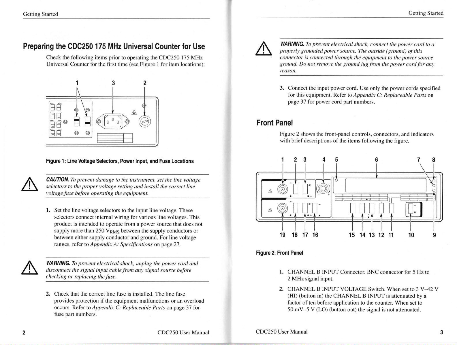
Universal Counter for the first time (see Figure I for item locations):
32
Figure 1 : Line Voltage Selectors, Power Input, and Fuse Locations
CAUTION. To prevent damage to the instrument, set the line voltage
A
selectors to the proper voltage setting and install the correct line
voltage fuse bofore operating the equipment.
1. Set the line voltage selectors to the input line voltage. These
selectors connect internal wiring for various line voltages. This
product is intended to operate from a power source that does not
supply more than 250 VRMs between the supply conductors or
between either supply conductor and ground. For line voltage
ra,nges, refeT to Appendix A: Specifications on pa.ge 27 .
WARNING. Ilo prevent electrical shock, connect the power cord to a
A
properly grounded power source. The outside ( ground) Of this
connector is cormected through the equipment to the power source
ground. Do not remove the ground lug from the power cord for any
reason.
3. Connect the input power cord. Use only the power cords specified
Front Panel
Figure 2 shows the front-panel controls, connectors, and indicators
with brief descriptions of the items following the figure.
Figure 2: Front Panel
for this equipment. Refer to Appendix C: Replaceable Parts on
page 37 for power cord part numbers.
78
A
2
WARNING. To prevent electrical shock, unplug the power cord and
disconnect the signal input cable from any signal source before
checking or replacing the fuse.
2. Check that the correct line fuse is installed. The line fuse
provides protection if the equipment malfunctions or an overload
occurs. FLefer to Appendix C.. Replaceable Parts on pa,ge 37 for
fuse part numbers.
CDC250 User Manual
1. CHANNEL 8 INPUT Connector. BNC connector for 5 Hz to
2 MHz signal input.
2. CHANNEL 8 INPUT VOLTAGE Switch. When set to 3 V42 V
(HI) (button in) the CHANNEL 8 INPUT is attenuated by a
factor of ten before application to the counter. When set to
50 mv-5 V (LO) (button out) the signal is not attenuated.
CDC250 User Manual
3
Page 9

Getting Started
Getting Started
3. CHANNEL 8 SLOPE Switch. Selects positive-going or
negative-going edge of the CHANNEL 8 signal for triggering.
When -(button in), the negative-going edge is selected; when +
(button out), the positive-going edge is selected.
4. TRIG LEVEL Control. Adjusts trigger threshold level on the
CHANNEL A INPUT signal. Pushing the knob in (PUSH
PRESET) sets this level at the midpoint of a symmetrical
sinewave. Pulling the knob out and rotating it varies the level
from negative (-) to positive (+) around the midpoint.
5. OVERRANGE Indicator. Lights whenever the range ot` the
display is exceeded. One or more most significant digits are not
displayed.
6. Display. Eight-digit, seven-segment, LED display with automatic
decimal point placement.
7. kHz/Lls Indicator. In FREQuency mode, indicates that the
frequency displayed is in kilohertz. In PERIOD or TIME Interval
mode, indicates that the period or time interval displayed is in
microseconds. (Not used in RATIO or TOTALize modes.)
8. MHz/ms Indicator. In FREQuency mode, indicates that the
frequency displayed is in megahertz. In PERIOD or TIME
Interval mode, indicates that the period or time interval displayed
is in milliseconds. (Not used in RATIO or TOTALize modes.)
9. GATE Indicator. Lights when a measurement is being taken.
10. POWER Switch. Turns the unit ON and OFF.
11. GAIT Switch (0.01 s, 0. I s, 1.Os, and 10s). This switch selects the
degree of display resolution in all modes except TOTALize.
12. FUNC (Function) Switch. Use to select any one of the following
as the operating mode:
I FREQ. Frequency counter mode for CHANNEL A INPUT
signal. readings are in kHz or MHz as selected by the
MHz/ms-kHz/pus switch (item 13). Resolution is as selected
by the GATE switch (item 11 ).
I PERIOD. The period of one cycle of the CHANNEL A
INPUT signal is displayed. Display reading is in milliseconds
or microseconds as selected by the MHz/ms-kHz/pus switch
(item 13). Resolution is as selected by the GATE switch
(item 11).
I RATIO. When this mode is selected, the unit measures the
ratio of the CHANNEL A frequency to the CHANNEL 8
frequency. Resolution is selected by the GAIE switch
(item 11).
I TIME. When this mode is selected, the unit measures the time
interval from an edge of the CHANNEL A signal to an edge
of the CHANNEL 8 signal. The positive-going or negative-
going edge of each signal is selected by the SLOPE switches
(items 17 and 3). The display is in microseconds or millisec-
onds, as selected by the MHz/ms-kHz/Its switch (item 13).
Resolution is selected by the GATE switch (item 11 ).
I TOTAL (Totalize). When this mode is selected, the unit
counts the cycles of the CHANNEL A input signal and
continuously displays that count. Totalization can be
controlled by a gate signal at the rear panel TOTALIZE
INPUT START/STOP connector (refer to jieczr Pcz#cJ on
page 7).
I CHECK. When this mode is selected, the unit displays the
frequency of the internal time base, providing a functional
check of performance.
13. MHz/ms-kHz/Lis Switch. When pushed in, this switch selects
megahertz display for frequency readings and millisecond display
for period and time interval readings. When released (button out),
it selects kilohertz display for frequency readings and microse-
cond for period and time interval readings. This switch is not
used in RATIO and TOTALize modes.
4
CDC250 User Manual
CDC250 User Manual
5
Page 10

Getting Started
Getting Started
14. HOLD Switch. Functions as follows:
I All modes except TOTALize:
Setting switch to ON (button in) locks the display at the
existing reading and resets the counter. Releasing the switch
(button out) starts a new measurement, and the display is
updated when this measurement is completed.
I TOTALize mode:
Setting switch to ON (button in) locks the display at the
existing reading and halts the totalizing process. When the
switch is released, counting resumes, provided that the gating
signal at the rear panel TOTALIZE INPUT START/STOP is
high or open.
15. RESET Switch. In all modes, pushing this momentary switch
resets the counter to zero. When it is released, the measurement
starts again.
16. CHANNEL A LOW PASS FILTER Switch. When ON (button
in), the CHANNEL A input signal is routed through a low-pass
fllter with a -3 dB point at about 10 kHz. Press in when checking
signals below 10 kHz to prevent high-frequency noise interfer-
ence.
17. CHANNEL A SLOPE Switch. Selects positive-going or
negative-going edge of the CHANNEL A INPUT signal for
triggering. When ON (button in), the negative-going edge is
selected; when OFF (button out), the positive-going edge is
selected.
18. CHANNEL A INPUT VOLTAGE Switch. When set to 3 V42 V
(HI) (button in) the CHANNEL A INPUT signal is attenuated by
a factor of ten before application to the counter. When set to 50
mv-5 V (LO) (button out) the signal is not attenuated.
19. CHANNEL A INPUT Connector. BNC connector for 5 Hz to
175 MHz signal input.
Plear Panel
ln addition to the line voltage selectors, power intput, and fuse
discussed .LTi Preparing the CDC250 I 75 MHz Universal Counter for
Use on page 2, the rear panel contains the items shown in Figure 3.
31
Figure 3: Plear Panel
1. TOTALIZE INPUT START/STOP Connector. BNC connector for
Totalize input. TTL logic high to start; TTL logic low to stop.
2. EXT/INT Switch. Selects the function of the OSCILLATOR
connector:
I EXT-provides a nominal 50 Q input impedance path for an
external 10 MHz time base.
I INT-monitors the internal time base oscillator.
3. EXT INPUT OSCILLATOR Connector. Serves as a monitoring
point for the internal time base oscillator, or provides an input
path for an external time base oscillator, depending on the
EXT/INT switch setting.
6
CDC250 User Manual
CDC250 User Manual
7
Page 11

Getting Started
`esx``` `` ` ` Sse§
Reference
General Considerations
Use the CDC250175 MHz Universal Counter for adjustment, test,
and repair of electronic equipment, such as audio instruments,
AMffM radios, TVs, CD radios, computer clocks, amateur radios,
and musical instruments. Refer to test and calibration manuals for
the specific equipment to locate the test points for required
frequencies.
Any frequency counter is best used in conjunction with a good
oscilloscope. The oscilloscope gives the operator a true picture of the
wave form being counted, In many cases, a filter may be needed to
remove &nwanted transients, radio frequency interference (RFI), or
other types of noise that may cause a counting error.
Duty Cycle Measurements
The TIME Interval mode can be used to determine the duty cycle of
a digital wave form by applying the same signal to CHANNEL A and
CHANNEL 8 and selecting the proper edges for triggering.
For an example, refer to Figure 4. The duty cycle, or ratio of on-time
to total period, is found by selecting the positive SLOPE (button out)
for CHANNEL A (so measurement starts at beginning of TI) and the
negative SLOPE (button in) for CHANNEL 8 (measurement ends at
end of TI). After this reading is taken, the period is measured by
using PERIOD mode (TefeT to PERIOD vs TIME Interval Mode on
page 10), and the duty cycle is obtained as follows:
Duty cycle =
TI
x 100%
PERIOD
8
CDC250 User Manual
CDC250 User Manual
9
Page 12

Reference
Reference
Using TI]lG LEVEL Control
When pushed in (PRESET), the TRIG LEVEL control sets the
trigger threshold to the approximate average of the CHANNEL A
signal. While this is sufficient for many signals, it is not adequate for
the wave form pictured in Figure 5. The lower dotted line represents
the trigger level set by the PRESET position. This level, the average
of the pulse train, is close to the level of noise present, and false
triggering could occur.
+T'+ I
1= period = I
Figure 4: Duty Cycle Measurement
PERloD vs. TIME Interval Mode
When measuring time interval between similar edges on the same
wave form (for example, positive-going edge to next positive-going
edge), it is advisable to use PERIOD rather than TIME, because of
the following:
I In TIME mode, the unit may tend to both trigger and stop on
the same edge, resulting in an incorrect reading. Wave forms
with fast rise times (such as ITL signals) are not as likely to
trigger and stop on the same edge as those with less steep
slopes, such as sine and triangle waves.
I The PERIOD mode is more accurate than TIME mode,
especially at finer resolutions. In TIME mode, the possibility
of error increases with the number of intervals averaged ( I,
10,100,1000) so that more digits tend to jitter as more are
selected. No actual improvement in resolution is gained. In
PERIOD mode the possibility of error is constant for all
GATE times.
Adjustable level
Preset level (average)
Figure 5: Example of Trigger Level Variation
By pulling the TRIG LEVEL control out and rotating it, the trigger
threshold can be varied above (+) or below(-) the average. In
Figure 5, an appropriate threshold setting would be somewhat above
the noise level as shown by the upper dotted line.
Display Interpretation
The following factors may affect the display:
I Display instability
t
'
I Measurement delays
I Intermeasurement Interval
10
CDC250 User Manual
CDC250 User Manual
11
Page 13

Reference
Reference
Display Instability
An uncertainty of ±1 least-significant digit is inherent in all digital
measurements. However, the following factors can cause greater
display uncertainties :
I Noise or ringing on the input signals can cause false triggering.
The display may be unstable; or it may appear stable, but be an
incorrect reading. The input-conditioning controls on this unit
can help to achieve stable triggering on noisy input signals.
I An unstable input frequency can cause display uncertainty. This
is common with LC (inductance-capacitance) and RC (resistance-
capacitance) oscillators; crystal-controlled oscillators are much
more stable.
I Trigger errors in period, time interval, and ratio measurements
can cause uncertainty. In PERIOD and RATIO modes, the
uncertainty can be reduced by taking the measurement over a
greater number of cycles; that is, selecting a finer GAIT time
(greater resolution). In TIME interval measurements, however,
multicycle measiirements are subject to a possible error of one
count per interval. Thus, the cumulative error is increased by
measuring over a greater number of intervals, and the result is
that all GATE settings have the same inherent resolution
(displaying more digits results in more digits being subject to
jitter).
Period and frequency are reciprocals of each other. At low
frequencies, more digits can be obtained (lessening the effects of
instability) by using PERIOD mode. High-frequency accuracy is
enhanced by using FREQuency mode. The crossover point
between the two modes is 10 kHz.
FREQUENCY. In frequency measurements, each GAIT setting
establishes a set gate time during which the measurement is made
(the GAIT indicator lights during this interval). Table I shows GATE
times for kHz and MHz modes.
Table 1 : Gate Time and Measurement Resolution in Frequency
Mode
Mode
kHz
kHz
kHz
kHz
MHz
MHz
MHz
MHz
Resolution
1 00 Hz
10Hz
1Hz
0.1 Hz
1Hz
100 Hz
10Hz
1Hz
Gate Time
0.01 s
0.1s
ls
10s
0.02 s
0.2s
2s
20s
Lower gate times result in smaller gate times. Smaller gate times are
useful when quicker updates are needed; for example, tuning an
oscillator. Better resolutions require longer update intervals.
PEl]IOD AND TIME INTEPVAL. PERIOD and TIME interval measure-
ments are made by averaging over a set number of cycles or time
intervals. That number is determined by the GATE switch settings as
shown in Table 2.
Measurement Delays
In all measurements except TOTALize, the display is updated at the
end of a finite measurement interval, which varies in length
according to the operating mode and resolution selected. For some
conditions, the delay can become significant. This should be
considered when changing resolution or operating mode, or when
using HOLD or RESET, because each of these actions initiates a new
measurement. Measurement delays for each mode are discussed here.
12
CDC250 User Manual
CDC250 User Manual
13
Page 14
Reference
Reference
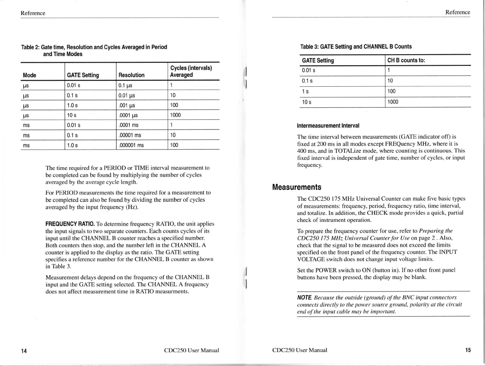
Table 2: Gate time, Resolution and Cycles Averaged in Period
and Time Modes
Mode
LIS
HS
LJS
LIS
ms
ms
ms
GATE Setting
0.01 s
0.Is
1.Os
10s
0.01 s
0.1s
1.Os
l]esolution
0.1 LIS
0.01 HS
•001 us
•0001 L,S
.0001 ms
.00001 ms
.000001 ms
The time required for a PERIOD or TIME interval measurement to
be completed can be found by multiplying the number of cycles
averaged by the average cycle length.
For PERIOD measurements the time required for a measurement to
be completed can also be found by dividing the number of cycles
averaged by the input frequency (Hz).
FREQUENCY RATIO. To determine frequency RATIO, the unit applies
the input signals to two separate counters. Each counts cycles of its
input until the CHANNEL 8 counter reaches a specified number.
Both counters then stop, and the number left in the CHANNEL A
counter is applied to the display as the ratio. The GATE setting
specifies a reference number for the CHANNEL 8 counter as shown
in Table 3.
Measurement delays depend on the frequency of the CHANNEL 8
input and the GAIT setting selected. The CHANNEL A frequency
does not affect measurement time in RATIO measurments.
Cycles (intervals)Averaged
1
10
100
1000
1
10
100
Table 3: GATE Setting and CHANNEL 8 Counts
GATE Setting
0.01 s
0.1s
ls
10s
Intermeasurement Interval
The time interval between measurements (GATE indicator off) is
fixed at 200 ms in all modes except FREQuency MHz, where it is
400 ms, and in TOTALize mode, where counting is continuous. This
fixed interval is independent of gate time, number of cycles, or input
frequency.
Measurements
The CDC250175 MHz Universal Counter can make five basic types
of measurements: frequency, period, frequency ratio, time interval,
and totalize. In addition, the CHECK mode provides a quick, partial
check of instrument operation.
To prepare the frequency counter for use, refer to Pnepczr!.„g ffec
CDC250 175 MHz Universal Counter for Use on po.ge 2 . AIso,
check that the signal to be measured does not exceed the limits
specified on the front panel of the frequency counter. The INPUT
VOLTAGE switch does not change input voltage limits.
Set the POWER switch to ON (button in). If no other front panel
buttons have been pressed, the display may be blank.
NOTE Because the outside (ground) Of the BNC input cormectors
connects directly to the power source ground, polarity at the circuit
end Of the input cable may be important.
CH 8 counts to:
1
10
loo
1000
14
CDC250 User Manual
CDC250 User Manual
15
Page 15

Reference
Reference
Frequency Measurements
Use the following procedure to make a frequency measurement:
1. Apply the signal to be measured to the CHANNI]L A INPUT
connector.
2. Set the FUNC switch to FREQ.
3. Select the measurement unit with the MHz/ms-kHz/pus switch
(button in for megahertz, button out for kilohertz).
The indicator light (next to the digital display) for the selected
measurement unit illuminates. If you are uncertain of the signal
frequency, you may need to try both ranges.
NOTE. Refer to ALppendix A.. Specif.+cariions on page 27 fior limits on
frequency ranges and sensitivities.
4. Set the GATE switch to the degree of resolution desired.
The display shows the frequency. The GAIT indicator lights
while each measurement is in progress, and the display is updated
at the end of each measurement interval.
The OVERRANGE indicator lights whenever the range of the
display is exceeded.
NOTE. If measurement delay or display instability is encountered, see
Display Interpretation a" pczgc J/.
5. Press the HOLD switch to lock the display. Release the HOLD
switch to begin taking new measurements.
When HOLD is released, a new measurement begins (GAIT
indicator lights), but the display continues to hold the old reading
until the new measurement is completed.
When RESET is released, a new measurement begins (GATE
indicator lights), but the display remains at zero until the new
measurement is completed.
6. Push in and release the RESET switch to reset the display to
Zero.
The following input controls can be used to condition the input as
needed to prevent miscounting from input noise or ringing:
LOW PASS FILTER Engaging the LOW PASS FILTER switch
routes the CHANNEL A input through a
low-pass filter before application to the
counter. This helps eliminate counting errors
in low-frequency measurements by reduc-
ing the effects of high-frequency noise.
INPUT VOLTAGE Engaging the CHANNEL A INPUT VOLT-
AGE switch (button in ) attenuates the
CHANNEL A signal approximately 10: I
before application to the counter. This helps
prevent miscounting caused by noisy or im-
properly terminated high-amplitude signals.
SLOPE
The CHANNEL A SLOPE switch selects
the positive or negative edge of the CHAN-
NEL A signal for triggering. Pushing the
switch in triggers the unit on the negative-
going edge; leaving it out causes triggering
on the positive-going edge. The CHANNEL
A SLOPE switch is bypassed whenever
FREQ MHz/ms is selected, and the unit
counts on the negative-going slope.
TRIG LEVEL
The CHANNEL A trigger threshold can be
varied by the TRIG LEVEL control as fol-
lows:
Pushing the control in (PRESET) fixes the
trigger level at roughly the average value of
the CHANNEL A input signal.
Pulling the control out and rotating it varies
the threshold level from negative (-) to posi-
tive (+) around the PRESET level.
For more information about the TRIG LEVEL control, refer to I/fz.„g
TRIG LEVEL Control on paige ++ .
16
CDC250 User Manual
CDC250 User Manual
17
Page 16

Reference
Reference
Period Measurements
In PERIOD mode, the unit displays the period, or time required for
one cycle of the input signal to occur. The measurement is made by
averaging over I,10,100, or 1000 cycles (depending on the GATE
switch setting).
Use the following procedure to make a PERIOD measurement:
1. Apply the signal to be measured to the CHANNEL A INPUT
connector.
2. Set the FUNC switch to PERIOD.
3. Select the measurement unit with the MHz/ms-kHz/rrs switch
(button in for milliseconds and button out for microseconds).
Either the MHz/ms or kHz/Hs indicator lights, showing the
selected measurement unit.
4. Select the resolution with the GATE switch.
GAIT switch settings (0.0ls, 0.1 s,I.Os,10s) refer to the kHz/Lls
mode. For MHz/ms mode, multiply the GATE switch value by
.001 to find the resolution in milliseconds.`The upper line of the
GAIT switch degree of settings (I,10,loo, and 1000) gives the
number of cycles averaged in the measurement.
NOTE. The 10 s GATE switch setting cannot be selected in the
millisecond PERIOD mode (MHz/ms-kHz/prs button in). The switch
will bypass I 0 s and go from 1.0 s back to 0.01 s.
The period is given in the display. The GATE indicator lights
while each measurement is in progress, and the display is updated
at the end of each measurement interval. (At higher frequencies,
the GATE indicator may flash too quickly to be seen.)
The OVERRANGE indicator lights whenever the range of the
display is exceeded.
NOTE. If measurement delay and display instability are encountered,
see Display Interpretation o" pc!gc I/.
5. Engage the HOLD switch (button in) to lock the display at the
existing reading. Release the HOLD switch.
When HOLD is released (button out), a new measurement begins
(GATE indicator lights), but the display continues to hold the old
reading until the new measurement is completed.
6. Push the RESET switch in to reset the display to zero. Release
the RESET switch.
When the RESET switch is released, a new measurement begins
(GATE indicator lights), but the display remains at zero until the
new measurement is completed.
The CHANNEL A input controls (LOW PASS FILTER, INPUT
VOLTAGE, SLOPE, and TRIG LEVER) may be used to condition
the input as described in Freqwc#cy A4cczfwremc#fs on page 16.
Frequency Platio Measurements
In this mode of operation, the counter displays the ratio of the
frequency applied to CHANNEL A to the frequency applied to
CHANNEL 8. The CHANNEL A frequency should preferably be
equal to or greater than that of CHANNEL 8, and both frequencies
must be within the limits listed on the front panel and in Appcjtdz*A..
Specifications on palge 2] .
Frequency ratio is determined by counting the number of CHANNEL
A cycles occurring during a specified number of CHANNEL 8
cycles (I,10,100, or 1000) and applying the result to the display.
Use the following procedure to make a RATIO measurement:
1. Connect the signals to be measured to the CHANNEL A and
CHANNEL 8 INPUT connectors.
NOTE. Connect both channels to the same signal fior a ratio of I.
18
CDC250 User Manual
CDC250 User Manual
19
Page 17

Reference
Reference
2. Set the FUNC switch to RATIO.
Both the MHz/ms and kHz/pus indicators are off because the
reading displayed is a ratio.
3. Set the GATE switch for the degree of resolution wanted.
This setting will also determine the number of CHANNEL 8
cycles used for the ratio measurement.
NOTE. The MHz/ms-kHz/prs switch setting is ignored in RATIO mode.
The frequency ratio is given by the display. The GAIT indicator
lights while each measurement is in progress, and the display is
updated at the end of each measurement interval. (At higher
CHANNEL 8 frequencies, the GAIE indicator may flash too
quickly to be seen.)
The OVERRANGE indicator lights whenever the range of the
display is exceeded.
NOTE. If measurement delay or display instability is encountered,
He/cr /a Display Interpi.etation a" pczgc //.
The CHANNEL A INPUT controls (INPUT VOLTAGE, SLOPE,
and TRIG LEVEL) can be used to condition the CHANNEL A input.
The CHANNEL 8 INPUT controls (INPUT VOLTAGE and SLOPE)
can be used to condition the CHANNEL 8 input. Refer to the
description of input controls on page 17.
Time Interval Measurements
ln TIME mode, the unit measiires the elapsed time from a selected
edge of the CHANNEL A wave form to a selected edge of the
CHANNEL 8 wave form.
For a stable reading, the two input signals should be related to each
other so that the time interval remains reasonably constant from one
measurement to the next. For example, two digital wave forms
derived from the same clock are suitable; two arbitrary frequencies
from separate function generators are not suitable.
Both inputs may be connected to the same signal for duty cycle
measurements (refer to Dwfy Cyc/c A4cczswrc#zc#/I on page 9).
Use the following procedure to make a Time Interval measurement:
1. Connect the signals to be measured to the CHANNEL A and
CHANNEL 8 INPUT connectors.
2. Set the FUNC switch to TIME.
20
4. Engage the HOLD switch (button in) to lock the display at the
existing reading. Release the HOLD switch.
When HOLD is released, a new measurement begins (GATE
indicator lights), but the display continues to hold the old reading
until the new measurement is completed.
5. Push the RESET switch in to reset the display to zero. Release
the RESET switch.
When RESET is released, a new measurement begins (GATE
indicator lights), but the display remains at zero until the new
measurement is completed.
CDC250 User Manual
The switch-setting label serves as a reminder that the measure-
ment starts at the CHANNEL A edge and stops at the
CHANNEL 8 edge.
3. Select the desired edge of each wave form with the CHANNEL A
and CHANNEL 8 SLOPE switches (button in (-) for negative-
going edge and button out (+) for positive-going edge).
NOTE. When measuring time interval between similar edges on the
same waveform (fior example, positive edge to next positive edge),
use PERIOD rather than TIME mode. Refer to General Cor\stder-
awions on page 9.
CDC250 User Manual
21
Page 18

Reference
Reference
4. Set the CHANNEL A TRIG LEVEL control to PRESET (knob
pushed in).
This ensures that both CHANNEL A and CHANNEL 8 are
triggering at the same level (approximately the average) on their
respective wave forms.
5. Select measurement units with the MHz/ms-kHz/ys button - in
for milliseconds, out for microseconds.
Either the MHz/ms or kHz/ws indicator will light, according to
your selection.
6. Set the GATIl switch to the degree of resolution wanted.
In TIME mode all resolution settings will have the same inherent
resolution, because if more periods are averaged, there is greater
accumulated error. Refer to D!.sp/czy J"sfc!b[./I.fy on page 11.
NOTE. In TIME MHz/ms mode the GAITE switch cannot be set to 10s.
The switch will bypass I Os, going from 1.Os back to 0.01 s.
The time interval is given by the display. The GATE indicator
lights while each measurement is in progress, and the display is
updated at the end of each measurement interval. (At higher
frequencies, the GATE indicator may flash too quickly to
be seen.)
The OVERRANGE indicator lights whenever the range of the
display is exceeded.
NOTE. If measurement delay or display instability is encountered, see
Display Interpretation o# pczgc //.
7. Engage the HOLD switch to lock the display at the existing
reading. Release the HOLD switch.
8. Push the RESET switch in to reset the display to zero. Release
the RESET switch.
When RESET is released, a new measurement begins (GATE
indicator lights), but the display remains at zero until the new
measurement is completed.
9. Do the following steps to measure the time interval for once-only
events:
a. Select the 1/0.01s GATE setting; this must be used for
single events because the others are all multiple-event
averaging.
b. Set the SLOPE switches for the anticipated level
transitions and push RHSET to prime the unit.
When the event has occurred (CHANNEL A transltlon
followed by CHANNEL 8 transition), the time interval is
displayed. For each single-event measurement, the counter
must again be primed by pressing RESET.
The following input controls can be used to condition the input:
LOW PASS FILTER Engaging the LOW PASS FILTER (but-
ton in) routes the CHANNEL A input
through a low-pass filter before applica-
tion to the counter. This helps eliminate
the effects of high-frequency noise in
the CHANNEL A input.
INPUT VOLTAGE
Engaging the CHANNEL A INPUT
VOLTAGE switch (button in ) attenuates
the CHANNEL A signal approximately
10: I before application to the counter.
This helps prevent miscounting caused
by noisy or improperly terminated high-
amplitude signals.
When HOLD is released, a new measurement begins (GATE
indicator lights), but the display continues to hold the old reading
until the new measurement is completed.
22
CDC250 User Manual
CDC250 User Manual
23
Page 19

Reference
Reference
Totalize Measurements
The TOTAL mode is used to count the total number of events
occurring during a specific time period. This time period can be
defined by front-panel switch action or by a gating signal applied to
the rear panel TOTALIZE INPUT START/STOP connector. Events
miist occur at least five times per second for accurate counting.
Use the following procedure to make a Totalize measurement:
1. Set the FUNC switch to TOTAL. GATE and MHz/ms-kHz/pus
switch settings are ignored.
2. If the counting is to be controlled electronically, connect the
gating signal to the real panel TOTALIZE INPUT START/
STOP connector.
A TTL high at this input enables the totalizing process; a TTL
low disables it, holding the display at the accumulated value. If
no signal is connected, the connector is pulled high internally so
that counting occurs.
3. Press the RESET switch to zero the counter.
If no gating signal is connected to the TOTALIZE INPUT
START/STOP connector, the unit starts counting as soon as the
RESET switch is released. If a gating signal is connected,
counting starts when RESET is released and the gating signal
goes high.
As the unit totalizes, it displays the count continually. Maximum
count is 99,999,999. If this is exceeded, the OVERRANGE
indicator lights, and the count begins at zero again.
4. Stop counting by one of three methods:
I Send a low gating signal to the TOTALIZE INPUT
START/STOP connector.
Counting stops and the display is held at the accumulated
total. Counting resumes when the gating signal again
goes high.
NOTE. The gating signal at the TOTALIZE INPUT START/STOP
connector halts totalization by inhibiting the CHANNEL A input
signal. It also blocks this signal in all other operating modes except
FREQ MHz. This should be considered if the input remains
connected during other measurements.
I Engage the HOLD switch (button in).
Counting stops and the display is held at the accumulated
total. Counting resumes when the switch is released.
I Press RESETatany time.
Clears the counter and resets the display to zero.
The CHANNEL A input controls (INPUT VOLTAGE, SLOPE, and
TRIG LEVEL) can be used to condition the input. Refer to the input
controls description on page 17.
Checking Instrument Operation
The CHECK mode provides a quick, partial check of instrument
operation.
Procedure. Use the following procedure to make a quick, general
check of instrument operation:
1. Set the FUNC switch to CHECK.
2. Set the MHz/ms-kllz/pus switch to kHz/pus (button out).
3. Check that the CDC250 displays match those listed in Table 4.
(Input controls have no effect in CHECK mode.)
4. For any setting in either kHz/pus or MHz/ms mode, press the
HOLD button.
This holds the display value and keeps the GATE indicator off for
as long as HOLD is on (button in).
24
CDC250 User Manual
CDC250 User Manual
25
Page 20

Reference
``` `..prj;:
Table 4: CHECK Mode Displays
Mode
kHz
kHz
kHz
kHz
MHz
MHz
MHz
GATE Switch Setting
0.01 s
0.1s
1.Os
10s
0.01 s
0.1s
1.Os
Display F]eading
10000.0 kHz
10000.00 kHz
10000.000 kHz
0000.0000 kHz
(OVEBBANGE lit)
10.0000 MHz
10.00000 MHz
10.000000 MHz
5. Press HOLD again to turn HOLD off (button out).
6. Check that the GATE indicator resumes flashing. (If a new GAIT
setting has been selected, the display is updated to the new value
after the first GATE interval.)
7. For any setting in either kHz/Lis or MHz/ms Mode, press RESHT.
This clears all digits to the left of the decimal point (leaving only
the decimal and the zeros that follow it). The GATE indicator
stays off as long as the RESET button is held in.
8. Release the RESET button.
9. Check that the GAIT indicator resumes flashing and the display
updates at the end of the first GAIE interval.
Appendix A: Specifications
Characteristics after one hour warmup time at 23° C ±5° C,
75% RH.
Table 5: Operational Characteristics
Frequency
FlangekHzMode
5 Hz to 10 MHz
MHz Mode
Accuracy
Besolution
Display
Period
Bange
Frequency Flange
Accuracy
Plesolution
Display
Ratio
Frequency BangeChannelA
Channel a
Accuracy
5 MHz to 175 MHz
±1 count ± time base error
0.1 Hz to 1 kHz, in decade steps
kHz or MHz with decimal point
0.5 HS to 0.2 s
5 Hz to 2 MHz
±1 count ± time base error ± trigger errorl
100 ps to 100 ns in decade steps
ms or LLs with decimal point
5 Hz to 10 MHz
5 Hz to 2 MHz
± resolution ± ratio x trigger errorl
1 Trigger error is typically ±0.3°/o of reading divided by the number of cycles
averaged for input signals greater than 100 mv with S/N ratio better than
40 dB.
26
CDC250 User Manual
CDC250 User Manual
27
Page 21

Appendix A: Specifications
Appendix A: Specifications
Table 5: Operational Characteristics (Cont.)
Ratio
Besolution
Display
CH 8 frequency
CH A frequency x N2
Numerical ratio with decimal point
Time Interval
Bange
Frequency Bange
Accuracy
Besolution
Display
0.5 us to 0.2 s
5 Hz to 2 MHz, square wave
±1 count ± time base error ± trigger errorl ± N2
100 ps to 100 ns in decade steps
ms or Lls with decimal point
Totalize
flange
Count Capability
Control
CHANNEL A Input
Bandwidth
SensitivitykHzMode5Hz to 10 MHz
5 Hz to 10 MHz
0 to 99,999,999 before OVEBPANGE
Start, stop, and reset controlled by front panel pushbuttons
or rear panel TOTALIZE INPUT STABT/STOP
5 Hz to 175 MHz, AC coupled
20 in VF"S
1 Trigger error is typically ±0.3°/a of reading divided by the number of cycles
averaged for input signals greater than 100 mv with S/N ratio better than
40 dB.
2 N=numberofcyclesaveraged; 1,10,100,orl000.
Table 5: Operational Characteristics (Cont.)
CHANNEL A Input
MHz Mode5MHz to 125 MHz
50 in V"s
125 MHz to 150 MHz
150 MHz to 175 MHz
Impedance
MaximumInputvoltage
Attenuation
Filter
Slope
Trigger Level
CHANNEL 8 Input
Bandwidth
Sensitivity
Impedance
MaximumInputvoltage
Attenuation
Slope
Time Base
Crystal frequency
Line Voltage Stability
Temperature Stability
Aging Plate
100 in VRMs
150 in VBMs
1 MQ paralleled by 40 pF
42 Vpk
Times 1 or times 10 (selectable)
Low pass < 10 kHz -3 dB (selectable)
Positive-going or negative-going (selectable)
Preset or variable
5 Hz to 2 MHz, AC coupled
30 mv V"s
1 MQ paralleled by 40 pF
42 Vpk
Times 1 or times 10 (selectable)
Positive-going or negative-going (selectable)
10 MHz
Less than cO.4 ppm with ±10°/o line voltage variation
Less than ±0.001% (±1 ppm) from 0° C to 40° C ambient
temperature
Less than ±3 ppm per year
28
CDC250 User Manual
CDC250 User Manual
29
Page 22

Appendix A: Specifications
Appendix A: Specifications
Table 5: Operational Characteristics (Cant.)
Display
Display
OVEPIBANGE Indication
Eight 0.43 inch, seven-segment digits with MHz/ms, kHz/Lis,
GATE, and OVEBPIANGE indicators
LED indicator lights when count exceeds 99999999 during
any selected gate time
Display Update TimekHzFBEQand
User-selected gate time of 0.01, 0.1, 1.0, or 10 s plus fixed
CHECK Modes
MHz FREQ Mode
PEBIOD< PIATIO, and TIME
Modes
TOTALIZE Mode
200 ms interval
User-selected gate time of 0.02, 0.2, 2.0, or 20 s plus fixed
400 ms interval
User-selected cycles averaging of 1,10,100, or 1000 cycles
plus fixed 200 ms interval
Continuous
Table`6: Physical Characteristics
Physical
Width
Height
Depth
Weight
240 mm (9.5 in)
64 mm (2.5 in)
230 mm (9.0 in)
2.0 kg (4.4 lb)
Table 8: Electrical Characteristics
Electrical
Line Voltage flange
Power Consumption
90 to 110, 108 to 132, 198 to 242, and 216 to 250 VAC at 50
to 60 Hz
21 VA,18 W maximum
Table 7: Environmental Characteristics
Environmental
Operating Temperature
Storage Temperature
oo c to 4oo C, 75°/o PIH
-2oo C to 6o° C, 8oo/o PlH
30
CDC250 User Manual
CDC250 User Manual
31
Page 23

Appendix A: Specifications
RERERERERE
Appendix 8: Maintenance
This appendix provides information for the basic maintenance of the
CDC250 175 MHz Universal Counter.
cleaning
To clean the frequency counter, use a soft cloth dampened in a
solution of mild detergent and water. Do not spray cleaner directly
onto the instrument, since it may leak into the cabinet and cause
damage.
Do not use chemicals containing benzine, benzene, toluene, xylene,
acetone, or similar solvents.
Do not use abl.asive cleaners on any portion of the frequency counter.
Preparing for Shipment
If the original packaging is unfit for use or not available, use the
following packaging guidelines:
1. Use a corrugated cardboard shipping carton having inside
dimensions at least three inches greater than the instrument
dimensions.
2. Put the instrument into a plastic bag or wrap to protect it from
dampness and loose packing material.
3. Place the instrument into the box and firmly stabilize it with
packing material.
4. Seal the cai.ton with shipping tape.
32
CDC250 User Manual
CDC250 User Manual
33
Page 24

Appendix 8: Maintenance
Appendix 8: Maintenance
Troubleshooting
Electronic maintenance on the Tektronix CDC250175 MHz
Universal Counter must be performed by a trained technician.
However, an operator can perform some basic and routine
maintenance. The frequency counter will give some indications of
problems to aid the operator.
WARNING. Ilo prevent electrical shock, unplug the power cord and
A
disconnect the signal input cable from any signal source before
checking or replacing the fuse.
No Display with Power On
If the display is not lighted, but the POWER button is pushed in and
the frequency counter power cord is plugged into an outlet, do the
following steps:
1. Check the line fuse. If the fuse is open, replace it.
2. If the line fuse is good, check the power outlet for proper voltage.
If the outlet voltage is incorrect, refer to the nearest Tcktronix
service center for repair.
A
Display On but Frequency Not Counted
If the display is on, but the frequency counter does not count, do the
following steps:
1. Check INPUT VOLTAGE level button for HI/LO level signal
input.
CAUTION. Disconnect signal cable from the CDC250175 MHz`
Universal Counter and the circuit being tested before checking
continuity-
2. If the INPUT VOLTAGE setting does not col.rect the problem,
check the signal input cable for continuity.
3. If the signal input cable is good, check output of the circuit or
equipment being tested with an AC voltmeter or oscilloscope.
4. If signal input cable is good, check LOW PASS FILTER button
position to make sui.e that the button position agrees with the
input signal frequency.
5. If the LOW PASS FIIJTER button is in the correct position, check
the frequency setting.
6. If the frequency setting is correct, refer to the nearest Tektronix
service center for repair.
A
34
WARNING. To prevent electric shock, disconnect the I)ower cord from
the power source and the CDC250175 MHz Universal Counter
before cl.ecking continuity.
3. If outlet voltage is correct, check power cord continuity. If the
power cord fails the continuity check, replace the power cord.
4. If the power cord passes the continuity check, refer to the nearest
Tektronix service center for repair.
CDC250 User Manual
CDC250 User Manual
35
Page 25

Appendix 8: Maintenance
REREillRERE
Appendix C: Replaceable Parts
Replaceable parts may be ordered directly from your authorized
Tektronix dealer.
Standard Accessories
The following items are shipped with the CDC250 175 MHz
Universal Counter:
Table 9: Standard Accessories
Accessory
Fuse, 3AG, 0.250 A, 250 V, SB
(90 -132 V operation)
CDC250 User Manual
115 V Power Cord
Optional Accessories
The following items are available as optional accessories:
Table 10: Optional Accessories
Accessory
Fuse, 3AG, 0.125 A, 250 V, SB
(198 -250 V operation)
230 V Power Cords
Tektronix Part Number
159-0187-00
070-7999-XX
Plefer to Table 11
Tektronix Part Number
159-0313-00
Refer to Table 11
36
CDC250 User Manual
CDC250 User Manual
37
Page 26

Appendix C: Replaceable Parts`
The following power cords are available.
Table 11 : Accessory Power Cords
Plug Configuration
\
Zfo
Tektronix PartNumber
Normal Usage
North America115V
Q
¥'
Europe230V
161 -0104-00
161 -0104-06
(I(¢
\=cs
United Kingdom230V
Australia230V
North Amerlca230V
o
Switzerland230V
161 -0104-07
161 -0104-05
161 -0104-08
161 -0167-00
38
CDC250 User Manual
 Loading...