

Page 1

xx
Tektronix
ZZZ
BERTScope
Remote Control Guide
www.tek.com
P077128400*
*
077-1284-00
Page 2

Copyright © Tektronix. All rights reserved. Licensed software products are owned by Tektronix or its subsidiaries
or suppliers, and are protected by national copyright laws and international treaty provisions.
Tektronix products are covered by U.S. and foreign patents, issued and pending. Information in this publication
supersedes that in all previously published material. Specifications and price change privileges reserved.
TEKTRONIX and TEK are registered trademarks of Tektronix, Inc.
Contacting Tektronix
Tektronix, Inc.
14150 SW Karl Braun Drive
P.O . B o x 5 0 0
Beaverto
USA
For product information, sales, service, and technical support:
n, OR 97077
In North America, call 1-800-833-9200.
Worldwide, visit www.tek.com to find contacts in your area.
Page 3

Table of Contents
Preface ............................................................................................................... v
Theory of operation............. ................................ ................................ ............... v
Getting started........... . . . . . . . . . ............. . . . . . . . . . .............. . . . . . . . . .............. . . . . . . . . ............. . . . . 1
Remote control overview ..................................................................................... 1
Set up the instrument for remote control operation ........................... ............................. 2
Command description ......................................................................................... 2
Command syntax ............. .................................. ................................ ............... 3
Features .......... .................................. ................................ ............................. 3
Operations ...................................................................................................... 4
Parameters ...................................................................................................... 4
Command status ............................................................................................... 5
Command error messages and codes . .................................. ................................ ..... 5
Communications timeouts ........... ................................ ................................ ......... 6
Command listing.................................................................................................... 7
Generator ................. ................................ ................................ ........................... 9
Generator Data Generator ................ ................................ ................................ ........ 15
Generator Pattern Start............................................................................................ 17
Generator Spread Spectrum Clock............................................................................... 17
Generator Clock Input ............................................................................................ 19
Generator Clock Output Positive .. . . . . . . . . ............ . . . . . . . . ............ . . . . . . . . .............. . . . . . . . ......... 21
Generator Clock Output Negative ............... ................................ ................................ 24
Generator Clock Output Pos/Neg................................................................................ 27
Generator Data Output Positive . . ........... . . . . . . . . . ........... . . . . . . . . . ........... . . . . . . . . . ............ . . . . . . . . 29
Generator Data Output Negative................. ................................ ................................ 32
Generator Data Output Pos/Neg ....... ................................ ................................ .......... 34
Generator Reference Clock Multiplier .......... . . . . . . . . ............ . . . . . . . . .............. . . . . . . . . ............ . . 35
Generator Trigger.................................. .................................. .............................. 37
Generator Error Inject............................................................................................. 38
Generator Stress Module (GSM) - Stressed Eye............................................................... 39
GSM - Stressed Eye Configure/Enable.......................................................................... 39
GSM - Stressed Eye Setup........................................................................................ 40
Detector............................................................................................................. 49
Detector Error Detector ....... .................................. ................................ .................. 52
Detector Start Detect .............................................................................................. 56
Detector Clock Input .............................................................................................. 56
Detector Data Input...................................... ................................ .......................... 57
Detector Blank Input .............................................................................................. 59
Detector Trigger ... ................................ ................................ ................................ 60
Detector Results ................................................................................................... 61
BERTScope Remote Control Guide i
Page 4

Table of Contents
Detector Symbo
Detector Convenience........................... .................................. ................................ 64
Detector Auto Align Results ..................................................................................... 64
Detector Optical Mode.. ................................ .................................. ........................ 65
Clock Recovery Option. .................................. ................................ ........................ 67
Clock recovery command summary............................................................................. 69
CRService : Clock Recovery Service ........... .................................. .............................. 72
CRControl : Clock Recovery Control....................... .................................. .................. 73
Clock Recovery Loop Response ............... ................................ ................................ .. 82
Clock Recovery SSC Waveform ................................................................................. 84
Clock Recovery Jitter Spectrum ... . . . . . . . . ................ . . . . . . . . ................ . . . . . . . . . . .............. . . . . . . 87
Clock Recovery Miscellaneous ........ ................................ ................................ .......... 91
Clock Recovery: Sample Program .............................................................................. 94
Transmitter Equalization (TXEQ) Option .................................................................... 101
TXEQ command summary ............. ................................ .................................. ...... 102
TXEQ remote control commands.............................................................................. 103
Analysis Engine........................ ................................ .................................. ........ 109
Basic BER.............. ................................ .................................. ........................ 113
Block Errors...................................................................................................... 114
Burst Length ................. ................................ ................................ .................... 117
Correlation........................................................................................................ 119
Error Free Interval... ................................ ................................ ............................ 122
Error Map......................................................................................................... 124
FEC Emulation..... .................................. ................................ ............................ 127
Pattern Sensitivity . . . .............. . . . . . . . . . ............... . . . . . . . . ................ . . . . . . . . ................ . . . . . . 133
Strip Chart .................... .................................. ................................ .................. 136
Physical Layer Test........................................ ................................ ...................... 137
Eye Diagram ..................................................................................................... 138
Eye: CleanEye ................................................................................................... 149
Eye: Enable Eye Measurement Overlay ............ ................................ .......................... 158
Eye: Data Collecting ............................................................................................ 168
Eye: Single Value Waveform............... ................................ .................................. .. 169
Eye: Optical Mode ........ ................................ .................................. .................... 170
Eye: Read Eye Measurement .. ................................ ................................ ................ 174
BER Contour................... .................................. ................................ ................ 177
BER Contour: Optical Mode................................................................................... 183
Jitter Map . . . . . ................ . . . . . . . . .............. . . . . . . . . . ............... . . . . . . . . .............. . . . . . . . . . ....... 1 84
Jitter Peak. . . .............. . . . . . . . . .............. . . . . . . . . . . .............. . . . . . . . . .............. . . . . . . . . . . .......... 197
Jitter Tolerance. . ................. . . . . . . . . . . .................. . . . . . . . . . . ................ . . . . . . . . . . ................ 205
Mask Test......................................................................................................... 210
Q-Factor .............. .................................. ................................ .......................... 216
l Filtering . . . . . . .............. . . . . . . . . . . .............. . . . . . . . . . . .............. . . . . . . . . . ........... 63
ii BERTScope Remote Control Guide
Page 5

Table of Contents
Mainframe.................... ................................ ................................ .................... 223
System View ..................................................................................................... 231
RAM Capture ...... .................................. ................................ ............................ 233
System Event Log ............................................................................................... 235
Configuration......................... ................................ ................................ ............ 237
Status Queries.................................................................................................... 239
Common Comm
File Transfer................ .................................. ................................ .................... 245
Appendix A: Sample Remote Programming ................................................................. 249
Connect the cables to the instrument ......... ................................ ............................ 249
Send commands to the instrument ........................................................................ 249
Run a test and read back the measurements ....................... .................................. .... 253
Index
ands.................. ................................ ................................ .......... 243
BERTScope Remote Control Guide iii
Page 6

Table of Contents
iv BERTScope Remote Control Guide
Page 7

Preface
Theory of operation
This document contains a comprehensive listing or remote control commands
for the Tektronix BERTScope family of products. It includes commands for the
different pl
for each of those commands.
The remote control features enable operation of instrument processes remotely
via an IEEE-488 communications connection. Remote control is implemented
using a text-oriented command protocol that enable you to set and query system
parameters, and to operate the analyzer in different modes, including live error
analysis and offline playback of previously recorded error data.
The text-oriented commands follow a basic three-part structure, consisting of one
word identifying the major feature being addressed, another word identifying
aspeci
The analyzer receives and operates on each command immediately. Command
execution sets a status variable that may be queried by the user to determine if
the previous command was successful. Alternatively, a mode can be selected in
which these statuses are automatically returned after each command execution.
atforms. Restrictions and separate parameters or ranges are noted
fic operation or parameter within that feature, and optional parameters.
This document describes how to interface with the analyzer using the IEEE-488
connection. The analyzer is an IEEE-488 bus peripheral only; it is not an
IEEE-488 bus controller and cannot produce SRQ signals. The IEEE-488 Setup
el. In the System View, touch the Tools tab, then the Remote button, then
pan
IEEE Address. Enter the unique address in the GPIB Address field.
r more technical assistance in programming your remote control applications,
Fo
please contact your local Tektronix representative.
BERTScope Remote Control Guide v
Page 8

Preface
vi BERTScope Remote Control Guide
Page 9

Getting started
Remote contro
loverview
The BERTScope analyzer and any connected BERTScope instruments can
be controlled remotely via either an IEEE-488 or a TCP/IP communications
connection
or a host PC.
The remote
computer via either an IEEE-488 or TCP/IP connection. It then routes the
commands to one or more BERTScope instruments, connected to the BERTScope
analyzer or host PC via USB.
If the local host is a BERTScope, then the BERTScope software gets a chance
to handle the command first. Any commands the BERTScope software doesn’t
understand are sent to the BERTScope instruemnt software, which then controls
the BERTScope instruments.
When a BERTScope instrument is connected to a BERTScope, you can inter-mix
BERTScope and BERTScope instrument commands in the same script, program,
or int
are routed to the remote control software directly. In this case, using the
BERTScope-specific commands will result in an error.
For most applications, a single BERTScope instrument is connected to a
BERTScope or host PC. In this case, the BERTScope instrument is automatically
detected and connected when the remote control software is started, and
automatically disconnected when the remote control software is stopped. There
is no need in this case to use the OPEN or CLOSE commands described later in
is section.
th
. The remote control software runs on either a BERTScope anaylyzer,
control software accepts text-oriented commands from a remote
eractive session. If the host is just an ordinary PC, then the commands
If more than one BERTScope instrument is connected (such as one or more Clock
ecovery instruments) to the BERTScope or host computer, the remote control
R
software will not connect automatically. In this case, the Remote computer
must issue a NAMES? query to discover the IDs of the connected BERTScope
instruments, and OPEN the one desired before issuing control commands. If the
Remote computer needs to control multiple BERTScope instruments, it would
OPEN, control, then CLOSE one, then OPEN, control, and CLOSE another. The
device that is OPEN is referred to as the current device throughout this d ocument.
Remote control is implemented using a text-oriented command protocol described
in the following pages of this document. These commands enable you to set
and query the system parameters of the BERTScope instruments, and to retrieve
measurements made by the instrument.
BERTScope Remote Control Guide 1
Page 10
Getting started
Set up the inst
rument for remote control operation
Remote setup is accessed from the System View.
1. In the System view, under the Tools tab Utilities heading, click the Remote
button to access the configuration panel.
2. Before beginning a remote control session, it is necessary to start the Remote
Client application, RemoteClient.exe, on the host computer.
If the host is a BERTScope, click the Remote button from the System View
To ols page. If the host computer is a normal PC, then just execute the
RemoteClient.exe, file.
3. If you are using GPIB to control the BERTScope, enable the IEEE Address
button.
If the button is not enabled, click the Disconnect button; it might take a few
seconds to enable the IEEE Address button.
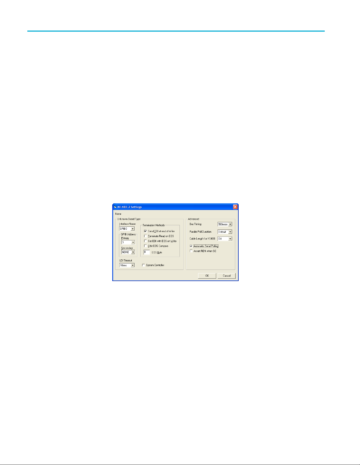
4. Click the IEEE Address button and enter the required information into the
NI-488.2 Settings dialog box.
Command description
Remote control communications are exchanged as ASCII strings over a LAN
telnet (TCP port 23) between the host computer and the analyzer. Select a
communications port to be used for access to the instrument's remote control
operations. If the port is set to NONE, then remote control is disabled.
The input values of commands are checked against the same ranges as the user
interface. If an input is received that is outside of this legal range, the input will
be clipped and recorded in the status queue.
It is recommended that you request the status of a command by sending
SYStemERRor? after each command. Besides telling you what has happened
with the command, this will also synchronize command transmission and
handling.
2 BERTScope Remote Control Guide
Page 11

Getting started
Command synta
x
Remote Control Command Lines are defined as ASCII text strings ending with
‘\r’ or ‘\n’.
The commands follow a basic three-part structure, consisting of one word
identifying the feature of the BERTScope instrument being addressed, another
word identi
The feature and operation are separated by a colon, and the operation and
parameter (if any), are separated by a space. The operation can be Double,
Integer, or Boolean numbers; a file path name; a special word; or a data type. For
a Boolean data type, the input can be ON, OFF, 1, or 0. The returned response
will be either 1 for true or 0 for false. A question-mark character (?) is added at
the end o
FEATURE:OPERATION PARAMETER
Commands and parameters are generally case-insensitive, with the notable
exception of those requiring a case-sensitive parameter for the Standard names.
Most commands have both a “long version” and “short version,” indicated by
capitalized versus lowercase letters. For example:
typed
are required; the lowercase letters are optional – commands are not case-sensitive.
The s
for example). You might want to use the long form in scripts or programs, to
increase code clarity.
fying a specific operation within that feature, and optional parameters.
f a command, without a space, to create a query.
GENerator:PATTern? can be
out exactly as shown, or as
hort form is convenient during interactive control (using a telnet session,
GEN:PATT? The capital letters and the colon (:)
Features
When command setup data uses a string as a parameter (a filename or path name,
for instance), enclose the string in double-quotes (“string”).
For every command processed, an error code will be returned. If the command
has a question mark (a query), the setup information is also returned.
The BERTScope remote control commands are divided into feature groups. The
number of features per each group depend on the BERTScope product.
In the first group are commands that handle device discovery and connection. You
can use these commands anytime, even if a current device has not been selected
yet (with the OPEN command). The NAMES, OPEN, and CLOSE commands are
allpartofthisgroup.
A second group consists of commands for controlling and monitoring a particular
BERTScope instruments. The current device must have been specified (using the
OPEN command) before to using any commands in this group.
BERTScope Remote Control Guide 3
Page 12

Getting started
Operations
Read-only properties
Read-write properties
In addition to t
to control the host computer display (VIEW, PTFILE, GUILOCKOUT), the
run state (RSTATE, RDURATION), and the overall program configuration
(SCONFIGURATION, RCONFIGURATION, ISSTATUS, RSSTATUS). These
commands primarily implement the functionality provided by the GUI Console
buttons.
Queryareadablepropertybyappendingaquestionmarktoit(withnospace
between the command and the question mark). For example:
CRS:OPEN?
returns the device name of the currently connected BERTScope CR. In most
cases, the returned values are all capitalized.
Query a read-write property by appending a question mark after it.
Set a read-write property by adding an appropriate parameter. For example:
CRS:OPEN “CRS_1234”
selects the BERTScope Clock Recovery unit with the device name CRS_1234 as
the current device, while
he various feature groups, several miscellaneous features exist
Write-only operation
Parameters
CRS:OPEN?
returns name of the device previously OPENed.
Question marks are illegal for write-only operation, and parameters may or may
not be required, depending upon the particular operation. For example:
CRS:CLOSE
requires no parameters, but
CRC:RCONFIGDISK “D:\BitAlyzer\Configurations\mycfg.cru”
requires the complete pathname of the BERTScope CR configuration file.
A parameter can be a double or integer number, Boolean (0 or 1), an enumerated
data type, or a string.
When a command uses a string as a parameter, the string is enclosed in double
quotes (
double quotes.
“string”). Filenames always require the absolute path, enclosed within
4 BERTScope Remote Control Guide
Page 13

Getting started
Command status
Parameters are
generally case-insensitive, with the notable exception of
case-sensitive Standard names. For example:
CRC:STANDARD “123abc”
and
CRC:DELETESTANDARD “123ABC”
are specifying different user-defined clock recovery standards.
The BERTScope instrument receives and operates on each command immediately.
The input values of commands are checked. If an input is received that is outside
of the legal range, the input will be clipped and recorded in the status queue.
Command execution sets a status variable that can be queried by the user to
determine if the previous command was successful.
Request the status of a command by sending:
SYSTEM:ERROR? or SYST:ERR?
This command retrieves items listed in the error status queue, in the format:
Command
Error messages
< n, “event/string” >
The status queue is first in, first out. It can contain up t o 100 error messages. If the
status queue overflows, the last error/event in the queue is replaced with Error
-350, “Queue overflow”. When all errors/events have been read from the
queue, further error/event queries will return
To clear the status queue all at once, send:
*CLS
error messages and codes
The following error messages might be returned:
"TOO MANY PARAMETERS"
"UNRECOGNIZED COMMA
"WRONG PARAMETER TYPE"
"TOO LITTLE PARAMETERS"
"WRONG PARAMETER FORMAT"
"WRONG PARAMETER NUMBER"
0, “NO ERROR”.
ND"
"WRONG ACTION-ONLY"
BERTScope Remote Control Guide 5
Page 14

Getting started
Error codes
The following error codes might be returned:
0 "NO ERROR"
-350 "Queue Overflow"
-10 File transfer error
-20 System
-30 Command error, see list of error messages
-40 No software option
Communications timeouts
Most commands issued to the BERTSope are processed quickly and return within
immediately. However a handful o f commands might require considerable
processing and take longer, including the following:
"WRONG QUERY-O
“REQUESTED <QUERY PARAMETER> IS NOT SUPPORTED ON THE
PLATFORM”
error or event
NLY"
Detector delay calibration — 8 seconds (approximately)
Generator delay calibration — 7 s econds
Detector auto align — 5 seconds
rator data signal enabling (BERTScope only) — 7 seconds
Gene
Run state enable (Physical layer tests that perform initial auto-align) —
conds
6se
As a result, programming the communications architecture with a two-second
meout for most command, and a 10-second timeout for the above-listed
ti
commands is one approach. Another approach is to set all communication
timeouts to be 10 seconds. Of course, commands that don’t require this much time
will not be affected by the longer timeout. This ensures that all commands can
complete without triggering communications timeouts.
6 BERTScope Remote Control Guide
Page 15

Command listing
Generator (See page 9, Generator.)
Data Generator (See page 15,
Generator Data Generator .)
Pattern Start (See page 17, Generator
Pattern Start.)
Spread Spectrum Clock (See page 17,
Generator Spread Spectrum Clock.)
Clock Input (See page 19, Generator
Clock Input.)
Clock Output + (See page 21,
Generator Clock Output Positive.)
Clock Output – (See page 24,
Generator Clock Output Negative.)
Clock Output +/– (See page 27, Generator
Clock Output Pos/Neg.)
Generator Stress Module (GSM) – Stressed Eye (See page 39, Generator Stress Module
(GSM) - Stressed Eye.)
GSM Configure/Enable (See page 39,
GSM - Stressed Eye Configure/Enable.)
Detector (See page 49, Detector.)
Error D etector (See page 52, Detector
Error Detector.)
Start Detect (See page 56, Detector
Start Detect.)
Clock Input (See page 56, Detector
Clock Input.)
Data Input (See page 57, Detector Data
Input.)
Blank Input (See page 59, Detector
Blank Input.)
Symbol Filtering (See page 63,
Detector Symbol Filtering.)
Clock Recovery (See page 67, Clock Recovery Option.)
CR Service (See page 72, CRService :
Clock Recovery Service.)
CR Control (See page 73, CRControl :
Clock Recovery Control.)
CR Loop Response (See page 82,
Clock Recovery Loop Response.)
CR SSC Waveform (See page 84,
Clock Recovery SSC Waveform.)
Data Output + (See page 29, Generator Data
Output Positive.)
Data Output – (See page 32, Generator Data
Output Negative.)
Data Output +/– (See page 34, Generator
Data Output Pos/Neg.)
(See page 35, Generator Reference Clock
Multiplier.)
Trigger (See page 37, Generator Trigger.)
Error Inject(See page 38, Generator Error
Inject.)
GSM Stress Setup (See page 40, GSM -
Stressed Eye Setup.)
Trigger (See page 60, Detector Trigger.)
Results (See page 61, Detector Results.)
Auto Align Results (See page 64, Detector
Auto Align Results.)
Optical Mode (See page 65, Detector Optical
Mode.)
Convenience (See page 64, Detector
Convenience.)
CR Jitter Spectrum (See page 87, Clock
Recovery Jitter Spectrum.)
CR Miscellaneous (See page 91, Clock
Recovery Miscellaneous.)
CR Sample Program (See page 94, Clock
Recovery: Sample Program.)
BERTScope Remote Control Guide 7
Page 16

Command listing
Transmitter Equalization (See page 101, Transmitter Equalization (TXEQ) Option.)
TXEQ command summary (See
page 102, TXEQ command summary.)
Analysis Engine (See page 109, Analysis Engine.)
Basic BER (See page 113, Basic BER.) 2D Error Map (See page 124, Error Map.)
Block Errors (See page 114, Block
Errors.)
Burst Leng
Length.)
Correlation (See page 119, Correlation.) Strip Chart (See page 136, Strip Chart.)
Error Free Interval (See page 122,
Error Free Interval.)
Physical Layer Test (See page 137, Physical Layer Test.)
Eye Diagram (See page 138, Eye
Diagra
ER Contour (See page 177, BER Contour.)
B
Mainframe (See page 223, Mainframe.)
System (See page 231, System View.)
System Event Log (See page 235, System Event Log.)
Configuration (See page 237, Configuration.)
Status Queries (See page 239, Status Queries.)
Common Commands (See page 243, Common Commands.)
th (See page 117, Burst
m.)
leanEye (See page 149,
Eye: C
Eye: CleanEye.)
Eye: Single Value Waveform (See
page 169, Eye: Single Value
form.)
Wave
: Data Collecting (See
Eye
page 168, Eye: Data Collecting.)
Eye: Optical Mode (See page 170,
Eye: Optical Mode.)
Eye: Read Eye Measurement
(See page 174, Eye: Read Eye
asurement.)
Me
TXEQ remote control commands (See
page 103, TXEQ remote control commands.)
FEC Emulation (See page 127, FEC
Emulation
Pattern Se
Sensitivity.)
Mask T
Jitter Map (See page 184, Jitter Map.)
Jit
Jitter Tolerance (See page 205, Jitter
Tolerance.)
Q-Factor (See page 216, Q-Factor.)
.)
nsitivity (See page 133, Pattern
Contour Optical M ode (See page 183,
BER Con
ter Peak (See page 197, Jitter Peak.)
tour: O ptical Mode.)
est (See page 210, Mask Test.)
8 BERTScope Remote Control Guide
Page 17

Generator
Complete command listing (See page 7, Command listing.)
DELAY:GENR e c a l ?
Retrieve the information that indicates whether Generator delay needs
recalibration. Query only. Note: Since monitoring for these calibrations is
suspended while Physical Layer tests are running, using this command under
those circumstances may not return an accurate result.
< 1 > Needs delay recalibrationReturns:
< 0 > Does not need delay recalibration
GENerato
r:CREFerence <EXTernal | INTernal>
GENerator:CREFerence?
Set or re
Params:
Returns:
trieve the Generator input clock reference.
<EXTernal>
<INTernal>
< EXTERNAL | INTERNAL >
External clock reference
Internal clock reference
GENerator:CSELect <INTernal | EXTernal>
rator:CSELect?
GENe
Set or retrieve the clock used by the Generator.
Params:
Returns:
<INTernal>
<EXTernal>
< INTERNAL | EXTERNAL >
Generator uses the internal clock synthesizer
Generator uses the external clock
BERTScope Remote Control Guide 9
Page 18

Generator
GENerator:CUT
OFFKHZ?
Retrieve the frequency at which the Generator switches to the DDR mode. Query
only.
GENerator:DDEFs <numeric>
GENerator:
DDEFs?
Set or retrieve the Generator data delay in femto-seconds.
Params: <numeric>
Returns: <numeric>
Set Generator data delay in fs
GENerator:DDELay <numeric>
GENerator:DDELay?
Set or retrieve the Generator data delay in picoseconds.
Params: <numeric>
Return
s:
<numer
ic>
or data delay.
Generat
Input out of range will be clipped and recorded in the
status queue.
When th
12,500 MHz], Data Delay is within range [0 to 3,000 ps].
e analyzer is operating within range [1,100 to
GENerator:DINVert <bool>
GENerator:DINVert?
Set or retrieve data inversion state for the Generator.
Params: <bool>
Returns:
< 1 > Data inversion is on
<0>
On=1,Off=0
Data inversion is off
GENerator:DRATe?
Retrieve the Generator data rate. Query only.
Returns: <numeric>
Generator data rate in bits/sec. “0” means “No Clock.”
10 BERTScope Remote Control Guide
Page 19

Generator
GENerator:EXT
Pagmode <SWITCHRISE | SWITCHFALL | AORBRISE |
AORBFALL | OFF>
GENerator:EXTPagmode?
Set or retrieve the Generator External Page Select mode.
Params:
Returns:
<SWITCHRISE> Switch momentarily to the other page on rising
edge
<SWITCHFALL> Switch momentarily to the other page on falling
edge
<AORBRISE> Switch to the other page on a rising edge
<AORBFALL> Switch to the other page on a falling edge
<OFF> External page select is off
< SWITCHRISE | SWITCHFALL | AORBRISE | AORBFALL | OFF >
GENerator:FULLRATEclock <bool>
GENerator:FULLRATEclock?
Set or retrieve Full Rate Clock property of the Generator.
Retur
ns:
<1>
<0>
Generator is in Full Rate Clock mode
Generator is in Half Rate Clock mode
GENerator:ICLock <numeric>
GENerator:ICLock?
Set or retrieve the internal clock synthesizer frequency of the Generator. May
require some delay to complete.
rams:
Pa
Returns: <numeric>
umeric>
<n
Generator internal clock synthesizer frequency in H z
Input out of range will be clipped and recorded in the
atus queue.
st
BERTScope Remote Control Guide 11
Page 20

Generator
GENerator:OFf
setfreq <numeric>
GENerator:OFfsetfreq?
Set or retriev
Params: <numeric>
Returns: <numeric>
e Generator’s Frequency Offset in PPM.
Generator’s Frequency Offset in PPM. Range [-500 to
+500]
GENerator:PCALibration
Perform Generator delay calibration. Action only. May require som e delay
to complete.
GENerator:PMMOD:DEViation <numeric>
GENerator:PMMOD:DEViation?
Set or retrieve Phase Modulation Deviation in UI. Range is from 0 to the value
dependent on PM.
Frequency:
250 kHz to ≤4MHz
2.5 kHz to < 250 KHz
10 Hz to <2.5 kHz
In the above formulas:
n = 0.5 for bit rates ≥11.2 Gbps
n = 1 for 6 Gbps ≤ bit rates < 11.2 Gbps
n = 2 for 3 Gbps ≤ bit rates < 6 Gbps
n = 4 for 1.5 Gbps ≤ bit rates < 3 Gbps
n = 8 for 750 Mbps ≤ bit rates < 1.5 Gbps
n = 16 for 375 Mbps ≤ bit rates < 750 Mbps
n = 32 for 187.5 Mbps ≤ bit rates < 375 Mbps
n = 64 for 100 Mbps ≤ bit rates < 187.5 Mbps
Decreasing 30 dB/decade to 12/n UI at 1 MHz and 1.5/n
at 4 MHz
Decreasing 20 dB/decade to 96/n UI at 250 kHz
Fixed 9600/n UI
Params: <numeric> Range: 0 to the upper limit as dependent on the PM Frequency
(see GEN:PMMOD:FREQ)
Returns: <numeric>
Nerator:PMMOD:ENABle <bool>
GE
GENerator:PMMOD:ENABle?
nable or disable Phase Modulation.
E
Params: <bool>
Returns:
<1>
<0>
On = 1, Off = 0
Generator Phase Modulation is enabled
Generator Phase Modulation is disabled
12 BERTScope Remote Control Guide
Page 21

Generator
GENerator:PMM
OD:FREQuency <numeric>
GENerator:PMMOD:FREQuency?
Set or retriev
Params: <numeric> Range [10 Hz to 4 MHz]
Returns: <numeric>
e Phase Modulation Frequency.
GENerator:REFIN:ENABLE <bool>
GENerator:REFIN:ENABLE?
Enable or disable the Generator Reference In.
Returns:
GENerato
<1>
<0>
Generator Reference In is enabled
Generator Reference In is disabled
r:REFIN:FREQuency <numeric>
GENerator:REFIN:FREQuency?
Set or re
Params: <numeric>
Retu
trieve the Generator Reference In Frequency in Hz.
Generator Reference In frequency in Hz
le values are:
Possib
10,000,000
100,000,000
50,000
106,2
156,250,000
133,330,000
70,000
166,6
200,000,000
rns:
<num
eric>
GENerator:REFOUT:ENABLE <bool>
GENerator:REFOUT:ENABLE?
Enable or disable the Generator Reference Out.
Params: <bool>
Returns:
<1>
<0>
On=1,Off=0
Generator Reference Out is enabled
Generator Reference Out is disabled
BERTScope Remote Control Guide 13
Page 22

Generator
GENerator:REF
OUT:FREQuency <numeric>
GENerator:REFOUT:FREQuency?
Set or retriev
Params: <numeric>
Returns: <numeric>
e the Generator Reference Out Frequency in Hz.
Generator Reference Out frequency in Hz
Possible val
10,000,000
100,000,000
106,250,00
156,250,000
133,330,000
166,670,0
200,000,000
GENerator:SYNFM:PRESent?
Retrieve
Params: <bool>
Returns:
whether SynFM module is present. Query only.
On=1,Off=0
<1>
<0>
SynFM module is present
SynFM module is not present
ues are:
0
00
14 BERTScope Remote Control Guide
Page 23

Generator Data Generator
Generator Dat
a Generator
Complete com
GENerator:ISERror
Inject a single error. Action only.
GENerator:LUPFilename?
Retrieve user pattern file that has been loaded to the Generator. Query only.
Returns:
GENerator:PATTern <PN7 | PN11 | PN15 | PN20 | PN23 | PN31 | USTart |
UCYCle | ALLZERO | PASSthrough>
GENerator:PATTern?
Set or retrieve the Generator data type.
Params:
urns:
Ret
mand listing (See page 7, Command listing.)
<"filenam
<PN7 | P
PN15 | PN20 |
PN23 | PN31>
<USTart> User pattern (See GEN:UPLoad command to load a
<UCY
<ALL
<PA
< PN7 | PN11 | PN15 | PN20 | PN23 | PN31 | USTART | UCYCLE | ZERO
| PASSTHROUGH >
e" >
N11|
Cle>
ZERO>
SSthrough>
Filename is enclosed in double quotes.
tor pseudo-random pattern data type.
Genera
attern file)
user p
User pattern cycle
All-zeros pattern
When corresponding option is purchased, Detector
s-Through mode outputs whatever the Detector has
Pas
just received.
GENerator:PSELect <A | B>
Nerator:PSELect?
GE
Set or retrieve the selected page of the user pattern loaded to the Generator.
<A> User pattern page AParams:
<B> User pattern page B
Returns:
< PAGEA | PAGEB >
GENerator:PSWitch
Switch the page of the user pattern loaded to the Generator. Action only.
BERTScope Remote Control Guide 15
Page 24

Generator Data Generator
GENerator:UPL
oad <"filename">
Load user pattern from the specified file. Action only.
Params:
<"filename">
Use the absolute path name and enclose the string in
double quotes.
GENerator:UPLPercent?
Retrieve the user pattern loading percentage completion value. Query returns 100
if the loading is complete. Query only.
Returns: < numeric >
The percentage of user pattern loaded into the
Generator
GENerator:UPLTracking<bool>
GENerato
r:UPLTracking?
Set or retrieve whether the Generator tracks the Detector when loading a user
pattern
. If the tracking is true, the command GEN:UPL <“filename”> loads the
user pattern into both the Generator and Detector.
Params: <bool>
Returns:
<1>
<0>
On=1,Off=0
Generator tracks Detector when loading
Generator does not track D etector when loading
rator:UPWLen?
GENe
Retrieve the word count from the Generator RAM. Query only.
Returns: < numeric >
The number of words in RAM
16 BERTScope Remote Control Guide
Page 25

Generator Spread Spectrum Clock
Generator Pat
tern Start
Complete com
GENerator:PSTart:TMODe <REDGe | FEDGe | DISabled>
GENerator:
Set or retrieve the trigger mode of the Generator pattern start input.
Params:
Returns:
mand listing (See page 7, Command listing.)
PSTart:TMODe?
<REDGe> Generator pattern start trigger at the rising edge
<FEDGe> Generator pattern start trigger at the falling edge
<DISabled>
< RisingEdge | FallingEdge| DISABLED >
Trigger is disabled.
Generator Spread Spectrum Clock
Complete command listing (See page 7, Command listing.)
GENer
GENerator:SSCMOD:DEViation?
ator:SSCMOD:DEViation <numeric>
r retrieve the SSC modulation deviation. Argument range is different for first
Set o
generation hardware (Option SSC) and second generation (Option XSSC).
Params: <numeric>
Returns: <numeric>
GENerator:SSCMOD:ENABle <bool>
GENerator:SSCMOD:ENABle?
Set or retrieve whether the SSC/XSSC option is enabled (option must be present
in order to enable; see GEN:SSCMOD:PRES command below).
Params: <bool>
Returns:
<1>
<0>
SSC modulation deviation in ppm.
Option SSC: Range [0 to 10,000] in Down spread or Up
spread mode; [0 to 5,000] in Center spread mode.
Option XSSC: Range is a function of data rate.
On=1,Off=0
SSC is enabled
SSC is disabled
BERTScope Remote Control Guide 17
Page 26

Generator Spread Spectrum Clock
GENerator:SSC
MOD:FREQuency <numeric>
GENerator:SSCMOD:FREQuency?
Set or retriev
e the SSC modulation frequency. Argument range is different for
first generation hardware (Option SSC) and second generation (Option XSSC).
Params: <numeric>
Returns: <numeric>
GENerator
:SSCMOD:PRESent <bool>
SSC modulation frequency in Hz.
Option SSC: Range [25,000 to 35,000]
Option XSSC:Range [20,000 to 160,000]. Note that
modulation deviation is uncalibrated for modulation
frequencies >40 kHz.
GENerator:SSCMOD:PRESent?
Set or ret
Params: <bool>
Returns:
rieve whether the SSC/XSSC option is present.
On=1,Off=0
<1>
<0>
SSC is present
SSC is not present
GENerator:SSCMOD:SIGnal <TRIANGLE | SINUSOID>
GENer
ator:SSCMOD:SIGnal?
Set or retrieve the SSC/XSSC modulation signal type.
Triangular-shaped modulationParams:
Returns:
<TRIANGLE>
<SINUSOID> Sinewave-shaped modulation
< TRIANGLE | SINUSOID >
GENerator:SSCMOD:SIGNALSETTABLE?
Returns whether the SSC/XSSC modulation signal is selectable. First-generation
SSC hardware only modulates in TRIANGLE mode. Query only.
eturns:
R
1>
<
<0>
Modulation is selectable (TRIANGLE or SINUSO ID)
(XSSC hardware)
Only modulates in TRIANGLE mode (1st generation
SSC hardware)
18 BERTScope Remote Control Guide
Page 27

Generator Clock Input
Generato
GENerator:SSC
GENerator:SSCMOD:TYPE?
Set or retriev
Params:
Returns:
rClockInput
Complet
GENerator:CINPut:TAC <bool>
GENera
Set or retrieve the termination AC of the Generator Clock input.
e command listing (See page 7, Command listing.)
tor:CINPut:TAC?
MOD:TYPE<UP | DOWN | CENTER>
e the SSC/XSSC modulation type.
<UP>
<DOWN>
<CENTER> Modulation
<UP|DOWN|CENTER>
Modulation deviation ranges from the nominal frequency
to the nomina
Modulation deviation is centered around the nominal
frequency.
minus the deviation amount to the nominal frequency.
l frequency plus the deviation amount.
deviation ranges from the nominal frequency
Params: <bool>
Returns:
<1>
<0>
On=1,Off=0
Generator Clock input termination AC is on
Generator Clock input termination AC is off
BERTScope Remote Control Guide 19
Page 28

Generator Clock Input
GENerator:CIN
Put:TVOLtage <numeric>
GENerator:CINPut:TVOLtage?
Set or retriev
Params: <numeric>
Returns: <numeric>
e the termination voltage of the Generator Clock input.
Generator Clock input termination voltage in mV. Range
[–2,000 to +2
recorded in the status queue.
,000]. Input out of range will be clipped and
GENerator:SUBRatediv<1|2|4|8|16|32|64|128>
GENerator
:SUBRatediv?
Set or retrieve the sub-rate clock output divider for the Generator’s internal
clock syn
Params:
Returns:
thesizer.
<1 | 2 | 4 | 8 | 16 | 32 | 64 | 128> 1 is full rate
< 1 (Full rate) | 2 | 4 | 8 | 16 | 32 | 64 | 128 >
20 BERTScope Remote Control Guide
Page 29

Generator Clock Output Positive
Generator Clo
ck Output Positive
Complete com
GENerator:COPositive:CLIPped?
Retrieve whether the Generator Clock+ output setting is clipped. Query only.
Returns:
GENerator:COPositive:ENABle <bool>
GENerator:COPositive:ENABle?
Set or retrieve whether the Generator Clock+ output is enabled. May require
some delay to complete.
Params: <bool>
s:
Return
GENerator:COPositive:IMPedance <numeric>
GENerator:COPositive:IMPedance?
mand listing (See page 7, Command listing.)
<1>
<0>
<1>
<0>
The Generator Clock+ output setting is clipped
The G enerator Clock+ output setting is not clipped
On=1,Off=0
Generator Clock+ output is enabled
Generator Clock+ output is disabled
Set or retrieve the impedance of the Generator Clock output positive. May require
some delay to complete.
ams:
Par
Returns: <numeric>
<nu
meric>
Generator Clock+ output impedance in Ohms. Range
[30 to 100,000]. Input out of range will be clipped and
orded in the status queue.
rec
GENerator:COPositive:LFAMily < CML | ECL | LVPECL | LVDS | SCFL>
Nerator:COPositive:LFAMily?
GE
Set or retrieve the Generator Clock+ output logic family.
Params:
Returns:
<CML | ECL | LVPECL |
LVD S | SC FL>
<CML | ECL | LVPECL |
LVD S | SC FL>
The Generator Clock+ output logic family
BERTScope Remote Control Guide 21
Page 30

Generator Clock Output Positive
GENerator:COP
ositive:SLAMplitude <numeric>
GENerator:COPositive:SLAMplitude?
Set or retriev
e the signal level amplitude of the Generator Clock+ output. May
require some delay to complete.
Params: <numeric>
Returns: <numeric>
GENerator
:COPositive:SLOFfset <numeric>
Generator Clock+ output signal level amplitude in mV.
Input out of range will be clipped and recorded in the
status queue.
Range [250 to 1,800]
Generator Clock+ output signal level amplitude
GENerator:COPositive:SLOFfset?
Set or ret
rieve the signal level offset of the Generator Clock+ output. May require
some delay to complete.
Params: <numeric>
Returns: <numeric>
Generator Clock+ output signal level offset in mV. Input
out of range will be clipped and recorded in the status
queue.
Range [–2,000 to +2,000]
Generator Clock+ output signal level offset
GENer
ator:COPositive:SLVHigh <numeric>
GENerator:COPositive:SLVHigh?
r retrieve the signal level V
Set o
of the Generator Clock+ output. May require
H
some delay to complete.
Params: <numeric>
Returns: <numeric>
Generator Clock+ output signal level V
[–1,750 to +3,000]. Input out of range will be clipped and
recorded in the status queue.
GENerator:COPositive:SLVLow <numeric>
GENerator:COPositive:SLVLow?
Set or retrieve the signal level V
of the Generator Clock+ output. May require
L
some delay to complete.
Params: <numeric>
Returns: <numeric>
Generator Clock+ output signal level V
[–2,250 to +1,000]. Input out of range will be clipped and
recorded in the status queue.
in mV. Range
H
in mV. Range
L
22 BERTScope Remote Control Guide
Page 31

Generator Clock Output Positive
GENerator:COP
ositive:TAC <bool>
GENerator:COPositive:TA C?
Set or retriev
e the termination AC of the Generator Clock+ output. May require
some delay to complete.
Params: <bool>
Returns:
GENerator
<1>
<0>
:COPositive:TVOLtage <numeric>
On=1,Off=0
Generator Clock+ output termination AC is on
Generator Clock+ output termination AC is off
GENerator:COPositive:TVOLtage?
Set or ret
rieve the termination voltage of the Generator Clock output positive.
Mayrequiresomedelaytocomplete.
Params: <numeric>
Returns: <numeric>
Generator Clock+ output signal level offset in mV. Range
[–2,000 to +2,000]. Input out of range will be clipped and
recorded in the status queue.
BERTScope Remote Control Guide 23
Page 32

Generator Clock Output Negative
Generator Clo
ck Output Negative
Complete com
GENerator:CONegative:CLIPped?
Retrieve whether the Generator Clock– output setting is clipped. Query only.
Returns:
GENerator:CONegative:ENABle <bool>
GENerator:CONegative:ENABle?
Set or retrieve whether the Generator Clock– output is enabled. May require
some delay to complete.
Params: <bool>
s:
Return
GENerator:CONegative:IMPedance <numeric>
GENerator:CONegative:IMPedance?
mand listing (See page 7, Command listing.)
<1>
<0>
<1>
<0>
The Generator Clock– output setting is clipped
The Generator Clock– output setting is not clipped
On=1,Off=0
Generator Clock– output is enabled
Generator Clock– output is disabled
Set or retrieve the impedance of the Generator Clock– output. May require some
delay to complete.
ams:
Par
Returns: <numeric>
<nu
meric>
Generator Clock– output impedance in Ohms. Range
[30 to 100,000]. Input out of range will be clipped and
orded in the status queue.
rec
GENerator:CONegative:LFAMily <CML | ECL | LVPECL | LVDS | SCFL>
Nerator:CONegative:LFAMily?
GE
Set or retrieve the Clock– output logic family.
Params:
Returns: <"string">
<CML|ECL|LVPECL|LVDS|
SCFL>
The Clock– output logic family
24 BERTScope Remote Control Guide
Page 33

Generator Clock Output Negative
GENerator:CON
egative:SLAMplitude <numeric>
GENerator:CONegative:SLAMplitude?
Set or retriev
e the signal level amplitude of the Generator Clock– output. May
require some delay to complete.
Params: <numeric>
Returns: <numeric>
Generator Clock– output signal level amplitude in mV.
Range [250 to 1,800]. Input out of range will be clipped
and recorded in the status queue.
GENerator:CONegative:SLOFfset <numeric>
GENerator:CONegative:SLOFfset?
Set or retrieve the signal level offset of the Generator Clock– output. May require
some delay to complete.
Params: <numeric>
Returns: <numeric>
Generator Clock– output signal level offset in mV. Range
[–2,000 to +2,000]. Input out of range will be clipped and
recorded in the status queue.
GENerator:CONegative:SLVHigh <numeric>
GENerator:CONegative:SLVHigh?
Set or retrieve the signal level V
of the Generator Clock– output. May require
H
some delay to complete.
Params: <numeric>
Returns: <numeric>
erator:CONegative:SLVLow <numeric>
GEN
Generator Clock– output signal level V
[–1,750 to +3,000]. Input out of range will be clipped and
recorded in the status queue.
GEN:CON:SLVL <numeric>
t or retrieve the signal level V
Se
of the Generator Clock– output. May require
L
some delay to complete.
Params: <numeric>
Returns: <numeric>
Generator Clock– output signal level V
[–2,250 to +1,000]. Input out of range will be clipped and
recorded in the status queue.
in mV. Range
H
in mV. Range
L
BERTScope Remote Control Guide 25
Page 34

Generator Clock Output Negative
GENerator:CON
egative:TAC <bool>
GENerator:CONegative:TAC?
Set or retriev
e the termination AC of the Generator Clock– output. May require
some delay to complete.
Params: <bool>
Returns:
GENerator
<1>
<0>
:CONegative:TVOLtage <numeric>
On=1,Off=0
Generator Clock– output termination AC is on
Generator Clock– output termination AC is off
GENerator:CONegative:TVOLtage?
Set or ret
rieve the termination voltage of the Generator Clock– output. May
require some delay to complete.
Params: <numeric>
Returns: <numeric>
Generator Clock– output termination voltage in mV.
Range [–2,000 to +2,000]. Input out of range will be
clipped and recorded in the s tatus queue.
26 BERTScope Remote Control Guide
Page 35

Generator Clock Output Pos/Neg
Generator Clo
ck Output Pos/Neg
Complete com
mand listing (See page 7, Command listing.)
GENerator:CLKDIVider <long>
GENerator:CLKDIVider?
Set or retrieve the value of the clock divider.
Params: < long >
Returns: < long >
Data rate (Gb/s) Ratios for main clock output
500-750 Mb/s
0.75-3 Gb/s
3-6 Gb/s
6-11.2 Gb/s
11. 2-12 Gb/s
12-26 Gb/s
1
Sub-rate clock connector can also output a full-rate stressed clock up to 11.2 Gb/s, or half-rate stressed clock at rates ≥11.2 Gb/s.
1, 2, 4, 5, 6, 7, 8, 9, 10, 12, 14, 16, 18, 20, 24, 32, 36 1, 2, 4
1, 2, 4, 5, 6, 7, 8, 9, 10, 12, 14, 16, 18, 20, 24, 30, 32, 32, 35, 36, 36, 40,
42, 45, 48, 50, 54, 56, 60, 64, 70, 72, 80, 81, 84, 90, 98, 108, 112, 126,
128, 144, 162
1, 2, 4, 5, 6, 7, 8, 9, 10, 12, 14, 16, 18, 20, 24, 30, 32, 32, 35, 36, 36, 40, 42,
45, 48, 50, 54, 56, 60, 64, 70, 72, 80, 81, 84, 90, 98, 100, 108, 112, 120, 126,
128, 140, 144, 160, 162, 168, 180, 192, 196, 216, 224, 252, 256, 288, 324
1, 2, 4, 5, 6, 7, 8, 9, 10, 12, 14, 16, 18, 20, 24, 30, 32, 32, 35, 36, 36, 40, 42,
45, 48, 50, 54, 56, 60, 64, 70, 72, 80, 81, 84, 90, 98, 108, 112, 126, 128, 140,
144, 144, 160, 162, 162, 168, 180, 192, 196, 200, 216, 224, 240, 252, 256,
280, 288, 320, 324, 360, 384, 392, 432, 448, 504, 512, 576, 648
2, 4, 8, 10, 12, 14, 16, 18, 20, 24, 28, 32, 36, 40, 48, 60, 64, 64, 70, 72,
72, 80, 84, 90, 96, 100, 108, 112, 120, 128, 140, 144, 160, 162, 168, 180,
196, 200, 216, 224, 240, 252, 256, 280, 288, 320, 324, 336, 360, 384, 392,
432, 448, 504, 512, 576, 648
2, 4, 8, 10, 12, 14, 16, 18, 20, 24, 28, 32, 36, 40, 48, 60, 64, 64, 70, 72,
72, 80, 84, 90, 96, 100, 108, 112, 120, 128, 140, 144, 160, 162, 168, 180,
196, 216, 224, 252, 256, 280, 288, 288, 320, 324, 324, 336, 360, 384, 392,
400, 432, 448, 480, 504, 512, 560, 576, 640, 648, 720, 768, 784, 864, 896,
1008, 1024, 1152, 1296
Value of clock divider from the following table
Value of clock divider from the following table; a return
value for 1 is 1 (Full-rate).
Ratios for sub-rate clock
1
output
1, 2, 4, 8
1, 2, 4, 8, 16, 32
1, 2, 4, 8, 16, 32, 64
2, 4, 8, 16, 32, 64
2, 4, 8, 16, 32, 64, 128
GENerator:COUTput:LPNSignals <bool>
GENerator:COUTput:LPNSignals?
Set or retrieve whether the Generator Clock output positive and negative are
linked. May require some delay to complete.
Params: <bool>
Returns:
<1>
<0>
On=1,Off=0
Clock outputs are linked
Clock outputs are not linked
GENerator:SUBRatediv<1|2|4|8|16|32|64|128>
BERTScope Remote Control Guide 27
Page 36

Generator Clock Output Pos/Neg
GENerator:SUB
Ratediv?
Set or retrieve the sub-rate clock output divider for the Generator’s internal
clock synthes
Params:
Returns:
izer.
<1|2|4|8|16|
32 | 64 | 128>
<1(Fullrat
4|8|16|32|64
| 128 >
e) | 2 |
Generator internal clock synthesizer subrate clock
output divid
er. 1 is full rate.
GENerator:SUBrate:STRess:CLKMODe <STRessed | SUBRate>
GENerator
:SUBrate:STRess:CLKMODe?
Set or retrieve the subrate clock mode.
Params:
Returns:
<STRessed> Clock Mode is Stressed
<SUBRate> Clock Mode is Subrate
< STRESSED | SUBRATE >
28 BERTScope Remote Control Guide
Page 37

Generator Data Output Positive
Generator Dat
a Output Positive
Complete com
GENerator:DOPositive:CLIPped?
Retrieve whether the Generator Data+ output setting is clipped. Query only.
Returns:
GENerator:DOPositive:ENABle <bool>
GENerator:DOPositive:ENABle?
Set or retrieve whether the Generator Data+ output is enabled. May require some
delay to complete.
Params: <bool>
s:
Return
GENerator:DOPositive:IMPedance <numeric>
GENerator:DOPositive:IMPedance?
mand listing (See page 7, Command listing.)
<1>
<0>
<1>
<0>
The Generator Data+ setting is clipped
The Generator Data+ setting is not clipped
On=1,Off=0
Generator Data+ output is enabled
Generator Data+ output is disabled
Set or retrieve the impedance of the Generator Data+ output. May require some
delay to complete.
Par
Re
ams:
turns:
<nu
umeric>
<n
meric>
Generator Data+ output impedance in Ohms. Range
[30 to 100,000]
ut out of range will be clipped and recorded in the
Inp
status queue.
GENerator:DOPositive:LFAMily < CML | ECL | LVPECL | LVDS | SCFL>
GENerator:DOPositive:LFAMily?
Set or retrieve the Generator Data+ output logic family.
Params:
Returns: <"string">
<CML | ECL |
LVPECL | LVDS |
SCFL>
Generator Data+ output logic family
BERTScope Remote Control Guide 29
Page 38

Generator Data Output Positive
GENerator:DOP
ositive:SLAMplitude <numeric>
GENerator:DOPositive:SLAMplitude?
Set or retriev
e the signal level amplitude of the Generator Data+ output. May
require some delay to complete.
Params: <numeric>
Returns: <numeric>
Generator Data+ output signal level amplitude in mV.
Range [50 to 1800]. Input out of range will be clipped
and recorded in the status queue.
GENerator:DOPositive:SLOFfset <numeric>
GENerator:DOPositive:SLOFfset?
Set or retrieve the signal level offset of the Generator Data+ output. May require
some delay to complete.
Params: <numeric>
Returns: <numeric>
Generator Data+ output signal level offset in mV. Range
[–2000 to +2000]. Input out of range will be clipped and
recorded in the status queue.
GENerator:DOPositive:SLVHigh <numeric>
GENerator:DOPositive:SLVHigh?
Set or retrieve the signal level V
of the Generator Data+ output. May require
H
some delay to complete.
Params: <numeric>
Returns: <numeric>
erator:DOPositive:SLVLow <numeric>
GEN
Generator Data+ output signal level V
[–1975 to +3000]. Input out of range will be clipped and
recorded in the status queue.
GENerator:DOPositive:SLVLow?
t or retrieve the signal level V
Se
of the Generator Data+ output. May require
L
some delay to complete.
Params: <numeric>
Returns: <numeric>
Generator Data+ output signal level V
[–2025 to +1100]. Input out of range will be clipped and
recorded in the status queue.
in mV. Range
H
in mV. Range
L
30 BERTScope Remote Control Guide
Page 39

Generator Data Output Positive
GENerator:DOP
ositive:SYMmetry <numeric>
GENerator:DOPositive:SYMmetry?
Set or retriev
Params: <numeric>
Returns: <numeric>
e the symmetry adjustment of the Generator Data+ output.
Generator Data+ output symmetry, in percent. Range
[30% to 70%].
recorded in the status queue.
Input out of range will be clipped and
GENerator:DOPositive:TA C <bool>
GENerator:DOPositive:TA C?
Set or retrieve the termination AC of the Generator Data+ output. May require
some delay to complete.
Params: <bool>
Returns:
<1>
<0>
On = 1, Off
Generat
Genera
=0
or Data+ output termination AC is on
tor D ata+ output termination AC is off
GENerator:DOPositive:TVOLtage <numeric>
GENerator:DOPositive:TVOLtage?
Set or retrieve the termination voltage of the Generator Data+ output. May require
some delay to complete.
Params: <numeric>
Returns: <numeric>
rator Data+ output termination voltage in mV.
Gene
Range [–2000 to +2000]. Input out of range will be
clipped and recorded in the status queue.
BERTScope Remote Control Guide 31
Page 40

Generator Data Output N egative
Generator Dat
aOutputNegative
Complete com
GENerator:DONegative:CLIPped?
Retrieve whether the Generator Data– output setting is clipped. Query only.
Returns:
GENerator:DONegative:ENABle <bool>
GENerator:DONegative:ENABle?
Set or retrieve whether the Generator Data– output is enabled. May require some
delay to complete.
Params: <bool>
s:
Return
GENerator:DONegative:IMPedance <numeric>
GENerator:DONegative:IMPedance?
mand listing (See page 7, Command listing.)
<1>
<0>
<1>
<0>
The Generator Data– output setting is clipped
The G enerator Data– output setting is not clipped
On=1,Off=0
Generator Data– output is enabled
Generator Data– output is disabled
Set or retrieve the impedance of the Generator Data– output. May require some
delay to complete.
ams:
Par
Returns: <numeric>
<nu
meric>
Generator Data– output impedance in Ohms. Range
[30 to 100,000]. Input out of range will be clipped and
orded in the status queue.
rec
GENerator:DONegative:LFAMily <CML | ECL | LVPECL | LVDS | SCFL>
Nerator:DONegative:LFAMily?
GE
Set or retrieve the Generator Data– output logic family.
Params:
Returns:
<CML|ECL|LVPECL|LVDS|
SCFL>
< CML | ECL | LVPECL | LVDS | SCFL >
The Generator Data– output logic family
32 BERTScope Remote Control Guide
Page 41

Generator Data Output Negative
GENerator:DON
egative:SLAMplitude <numeric>
GENerator:DONegative:SLAMplitude?
Set or retriev
e the signal level amplitude of the Generator Data– output. May
require some delay to complete.
Params: <numeric>
Returns: <numeric>
Generator Data– output signal level amplitude in mV.
Range [50 to 1800]. Input out of range will be clipped
and recorded in the status queue.
GENerator:DONegative:SLOFfset <numeric>
GENerator:DONegative:SLOFfset?
Set or retrieve the signal level offset of the Generator Data– output. May require
some delay to complete.
Params: <numeric>
Returns: <numeric>
Generator Data– output signal level offset in mV. Range
[–2000 to +2000]. Input out of range will be clipped and
recorded in the status queue.
GENerator:DONegative:SLVHigh <numeric>
GENerator:DONegative:SLVHigh?
Set or retrieve the signal level V
of the Generator Data– output. May require
H
some delay to complete.
Params: <numeric>
Returns: <numeric>
erator:DONegative:SLVLow <numeric>
GEN
GENerator:DONegative:SLVLow?
t or re trieve the signal level V
Se
of the Generator Data– output. May require
L
some delay to complete.
Params: <numeric>
Returns: <numeric>
Generator Data– output signal level V
[–2025 to +1100mV]. Input out of range will be clipped
and recorded in the status queue.
Generator Data– output signal level V
Range [–1975 to +2900]. Input out of range will
be clipped and recorded in the status queue.
L
in mV.
H
in mV. Range
BERTScope Remote Control Guide 33
Page 42

Generator Data Output Pos/Neg
GENerator:DON
egative:SYMmetry <numeric>
GENerator:DONegative:SYMmetry?
Set or retriev
Params: <numeric>
Returns: <numeric>
e the symmetry adjustme nt of the Generator Data– output.
Range [30% to 70%]. Input out of range will be clipped
and recorded
in the status queue.
GENerator:DONegative:TAC <bool>
GENerator
:DONegative:TAC?
Set or retrieve the termination AC of the Generator Data– output. May require
some dela
Params: <bool>
Returns:
ytocomplete.
<1>
<0>
On=1,Off=0
Generator Data– output termination AC is on
Generator Data– output termination AC is off
GENerator:DONegative:TVOLtage <numeric>
GENera
tor:DONegative:TVOLtage?
Set or retrieve the termination voltage of the Generator Data– output. May require
some d
elay to complete.
Params: <numeric>
Retu
rns:
<num
eric>
Generator Data Output Pos/Neg
Complete command listing (See page 7, Command listing.)
GENerator:DOUTput:LPNSignals <bool>
GENerator:DOUTput:LPNSignals?
Set or retrieve whether the Generator Data± outputs are linked. May require
some delay to complete.
Params: <bool>
Returns:
<1>
<0>
Generator Data– output termination voltage in mV.
e [–2000 to +2000]. Input out of range will be
Rang
clipped and recorded in the status queue.
On=1,Off=0
Generator Data± outputs are linked
Generator Data± outputs are not linked
34 BERTScope Remote Control Guide
Page 43

Generator Reference Clock Multiplier
Generator Ref
erence Clock Multiplier
Complete com
GENerator:RCM:ENable <bool>
GENerator:
Enable or disable the reference clock multiplier. The internal clock can specify
either RCM
Params: <bool>
Returns:
Example: GEN:RCM:En 1 enables the reference clock multiplier.
GENerator:RCM:GENERAL <long>, <double>
This is a general purpose command used to set the reference frequency and
multiplier values of reference clock multiplier. The range of the reference clock
frequency multiplied by the multiplier value should be in the range of 1E9 to
32E9.
Action only.
mand listing (See page 7, Command listing.)
RCM:ENable?
mode or Synthesizer mode.
On=1,Off=0
<1>
<0>
RCM m ode; the reference clock multiplier is enabled.
Synthesizer mode; the reference clock multiplier is
d and sets the internal clock to Synthesizer
disable
mode.
Params:
< long >
< double > The multiplier value.
The reference clock frequency.
GENerator:RCM:MIPI <long>, <double>
Set the reference frequency and multiplier values of reference clock multiplier of
the MIPI M-PHY standard. Action only.
Params:
Reference clock frequency Multiplier values
19200000 65, 76, 130, 152, 260, 304
26000000 48, 56, 96, 112, 192, 224
38400000 32.5, 38, 65, 76, 130, 152
52000000 24, 28, 48, 56, 96, 112
< long >
< double >
The reference clock frequency with one of the following
values: 19200000, 26000000, 38400000, 52000000.
The multiplier value, dependent on the reference clock
frequency; refer to the following table.
Example: GEN:RCM :MIPI 26000000, 48
BERTScope Remote Control Guide 35
Page 44

Generator Reference Clock Multiplier
GENerator:RCM
:MODE?
Returns the current standard of the reference clock multiplier. Query only.
Returns: <”string”>
GENerator:
RCM:MULTIplier?
PCIE1, PCIE2, PCIE3, PCIE4, MIPI, SDGEN2,
GENERAL
Returns the current clock multiplier value. Query only.
Returns: < double >
GENerator:RCM:PCIE1
Set the reference frequency and multiplier values of the reference c lock multiplier
to the PCIE1 standard. Action only.
GENerator:RCM:PCIE2
Set the r
eference frequency and multiplier values of the reference clock multiplier
to the PCIE2 standard. Action only.
GENera
tor:RCM:PCIE3
Set the reference frequency and multiplier values of the reference c lock multiplier
PCIE3 standard. Action only.
to the
GENerator:RCM:PCIE4
Set the reference frequency and multiplier values of the reference c lock multiplier
to the PCIE4 standard. Action only.
GENerator:RCM:SDGEN2 <long>, <double>
Sets the reference frequency and multiplier values of reference clock multiplier of
the SD UHS-II Gen 2 standard. Action only.
rams:
Pa
Returns:
ong >
<l
< double >
< ref frequency > < multiplier >
The reference clock frequency as an integer between
52000000 and 104000000
The multiplier value of either 30 or 60.
Example: GEN:RCM:SDGEN2 52000000, 60
36 BERTScope Remote Control Guide
Page 45

Generator Trigger
Generator Tri
gger
Complete com
GENerator:TOFFset <numeric>
GENerator:
Set or retrieve the Generator Trigger offset.
Params: <numeric>
Returns: <numeric>
GENerator:TOMethod <PCYCle | CLOCk>
GENerator:TOMethod?
Set or retrieve the Generator Trigger out method.
Params
Returns:
mand listing (See page 7, Command listing.)
TOFFset?
Generator Trigger offset
128-bit words. Range [0 to (Pattern Size – 1)] for all the
PRBS patterns. For others, the range is [0 to 0]. Input
out of range will be clipped and recorded in the status
queue.
:
<PCYCle> Generator Trigger out method is pattern cycle
<CLOCk> Generator trigger out method is a divided-down
clock/256
< PatternCycle | Clock/64 >
BERTScope Remote Control Guide 37
Page 46

Generator Error Inject
Generator Err
or Inject
Complete com
GENerator:EIEType < 1B IT | 2BITs | 4BITs | 8BITs | 16Bits | 32Bits | 64Bits |
128Bits>
GENerator:EIEType?
Set or retrieve the Generator Error Inject type. May require some delay to
complete.
Params:
Returns:
GENerator:EIINterval <numeric>
GENerator:EIINterval?
Set or retrieve the Generator Error Inject interval. May require some delay to
complete.
Params: <numeric>
Returns: <numeric>
mand listing (See page 7, Command listing.)
<1Bit | 2Bits | 4Bits
| 8Bits | 16Bits |
32Bits | 64Bits |
128Bits>
< 1B IT | 2BITs | 4BITs | 8BITs | 16Bits | 32Bits | 64Bits | 128Bits >
Generator error inject type is: 1, 2, 4, 8, 16, 32, 64, or
128 bit(s)
Generator Error Inject interval in bits
Range [16,384 to 2,147,483,520]; must be modulo 128.
Input out of range will be clipped and recorded in the
status queue.
GENerator:EIMode <CONTinuous | MANual | EXTernal | OFF>
GENerator:EIMode?
Set or retrieve the Generator Error Inject mode. May require some delay to
complete.
Params:
Returns:
<CONTinuous> Generator Error Inject mode is continuous
<MANual>
<EXTernal>
<OFF> Generator Error Inject is off
< CONTINUOUS | MANUAL | EXTERNAL | OFF >
Generator Error Inject mode is manual
Generator is set to inject a single error on receipt of an
external signal
GENerator:IBER?
Retrieve the injected BER of the Generator. Query only.
Returns: <numeric>
Generator injected bit error rate
38 BERTScope Remote Control Guide
Page 47

Generator Stress Module (GSM) - Stressed Eye
Complete command listing (See page 7, Command listing.)
Before using the GSM commands, send GSM:STRess:ENABle 1 to enable all
stress features (see GSM:STRess).
GSM Configure/Enable(See page 39, GSM - Stressed Eye Configure/Enable.)
GSM Stress Setup(See page 40, GSM - Stressed Eye Setup.)
GSM - Stressed Eye Configure/Enable
Complete command listing (See page 7, Command listing.)
Before using the GSM commands, send GSM:STRess:ENABle 1 to enable all
stress features (see GSM:STRess below).
GSM:RCONfiguration <“filename”>
RestoreStressconfiguration. Action only.
Params:
ns:
Retur
GSM:SCONfiguration <“filename”>
Save Stress configuration. Action only.
Params:
Returns:
name”>
<“file
< filename >
lename”>
<“fi
ename >
< fil
uration filename enclosed in double
Config
quotes.
figuration filename enclosed in quotes.
Con
BERTScope Remote Control Guide 39
Page 48

GSM - Stressed Eye Setup
GSM:STRess:EN
ABle <bool>
GSM:STRess:ENABle?
Set or retrieve whether the entire global stress feature is enabled. The entire stress
feature includes jitter insertion of sinusoidal jitter (SJ), external sinusoidal jitter
(EXSJ), random jitter (RJ), PRBS jitter (BUJ) and external high frequency jitter
(EXHF).
There are commands to enable each individual stress insertion, such as
GSM:SJitter:ENABle; however, unless the Stress Feature is enabled using this
command, those individual jitter insertion enabling commands do not enable any
jitter insertion. For example, if one sent a GSM:SJ:ENAB 1 without enabling the
stress feature (query GSM:STR:ENAB? returns 0), the system merely caches the
SJ Enable value. The next time GSM:STR:ENAB 1 is sent, the SJ is then enabled.
After the stress feature is enabled, one can still enable or disable individual types
of jitter insertion by sending the corresponding ENABle command.
This command corresponds to the Clock control’s “Jitter Insertion Enabled” menu
item in the Generator view.
Params: <bool>
Returns:
< 1 > All stress enabled
< 0 > All stress disabled
On=1,Off=0
GSM - Stressed Eye Setup
Complete command listing (See page 7, Command listing.)
GSM:BUJitter:AMPUi <numeric>
GSM:BUJitter:AMPUi?
Set or retrieve the PRBS jitter amplitude in percent of UI.
Params: <numeric>
Returns:
GSM:BUJitter:ENABle <bool>
GSM:BUJitter:ENABle?
Set or retrieve whether the PRBS jitter on the clock is enabled.
Params: <bool>
Returns:
< double %UI> Returns PRBS jitter amplitude in percent of
<1>
<0>
Range [0 to 50%]. The amplitude limits
change with regard to the analyzer’s
operating frequency.
UI.
On=1,Off=0
PRBS jitter on the clock is enabled
PRBS jitter on the clock is disabled
40 BERTScope Remote Control Guide
Page 49

GSM - Stressed Eye Setup
GSM:BUJitter:
FREQuency <numeric>
GSM:BUJitter:FREQuency?
Set or retrieve the PRBS jitter frequency in Hz.
Params: <numeric> Range [100,000,000 to 2,000,000,000]
Returns: < numeric >
GSM:BUJitter:TYPE <PRBS7 | PRBS10 | PRBS11>
GSM:BUJitter:TYPE?
Set or retrieve the PRBS jitter type.
Params:
Returns:
<PRBS7> Insert PRBS7 jitter
<PRBS10> Insert PRBS10 jitter
<PRBS11> Insert PRBS11 jitter
< PRBS7 | P RBS 10 | PRBS11 >
GSM:EXHFrequency:ENABle <bool>
GSM:EXHFrequency:ENABle?
Set or retrieve whether the external high frequency jitter is enabled.
Params: <bool>
Returns:
<1>
<0>
On = 1, Off = 0
External high frequency jitter is enabled
External high frequency jitter is disabled
GSM:EXSJitter:AMPUi <numeric>
GSM:EXSJitter:AMPUi?
Set or retrieve the external sinusoidal jitter amplitude in percent of UI.
Params: <numeric>
Returns: < numeric >
Range [0 to Maximum allowed %UI]. The
amplitude limits change with regard to the
analyzer operating frequency.
GSM:EXSJitter:MODE
Command is obsolete; see GSM:EXSJitter:INVErt and GSM:EXSJitter:ENABle.
GSM:EXSJitter:ENABle <bool>
GSM:EXSJitter:ENABle?
Enable/disable External Sinusoidal Jitter.
Params: <bool>
Returns:
<1>
<0>
On=1,Off=0
EXS Jitter is enabled
EXS Jitter is disabled
BERTScope Remote Control Guide 41
Page 50

GSM - Stressed Eye Setup
GSM:EXSJitter
:INVErt <bool>
GSM:EXSJitter:INVErt?
Set or retrieve invert state of EXS Jitter.
Params: <bool>
Returns:
<1>
<0>
On=1,Off=0
EXS Jitter is inverted
EXS Jitter is not inverted
GSM:F2Jitter:AMPUi <numeric>
GSM:F2Jitter:AMPUi?
Set or retrieve the F/2 Jitter amplitude.
Params: <numeri
s:
Return
< numer
c>
ic >
F/2 Jitter amplitude in %UI
GSM:F2Jitter:AVAilable?
Checks to see if the F/2 Jitter option is available. Query only.
Returns:
<1>
<0>
F/2 Jitter is available
F/2 Jitter is not available
GSM:F2Jitter:ENABle <bool>
GSM:F2Jitter:ENABle?
Set or retrieve whether F/2 Jitter is enabled.
Params: <bool>
Returns:
<1>
<0>
On=1,Off=0
F/2 Jitter is enabled
F/2 Jitter is disabled
GSM:F2Jitter:MAXAmpui?
Returns the maximum %UI for the current F/2 Jitter synthesizer frequency. Query
only.
Returns <numeric>
Maximum %UI for F/2 J itter synthesizer
frequency
GSM:LFRJ:AMPUI <numeric>
GSM:LFRJ:AMPUI?
Set or retrieve the low frequency random jitter amplitude in percent of UI.
Params: <numeric>
Returns: < numeric >
LFR Jitter amplitude in %UI
42 BERTScope Remote Control Guide
Page 51

GSM - Stressed Eye Setup
GSM:LFRJ:ENAB
LE <bool>
GSM:LFRJ:ENABLE?
Set or retrieve whether low frequency random jitter is enabled.
Params: <bool>
Returns:
< 1 > LFR Jitter is enabled
< 0 > LFR Jitter is disabled
On = 1, Off = 0
GSM:LFSJ:AMPPS <numeric>
GSM:LFSJ:AMPPS?
Set or retrieve the low f
Params: <numeric>
Returns: < numeric >
requency sinusoidal jitter amplitude in picoseconds.
LFS Jitter amplitude in ps
GSM:LFSJ:ENABLE <bool>
GSM:LFSJ:ENABLE?
Set or retrieve whether low frequency sinusoidal jitter is enabled.
Params: <bool>
Returns:
<1>
<0>
On = 1, Off = 0
LFS Jitter is enabled
LFS Jitter is disabled
GSM:LFSJ:FREQ <numeric>
GSM:LFSJ:FREQ?
Set or retrieve the low frequency sinusoidal jitter frequency in Hz.
Params: <numeric>
Returns: < numeric >
LFSJ frequency in Hz
GSM:MMDLYENable <bool>
GSM:MMDLYENable?
Enable or disable the DAC-based delay function. This command is required
before starting to adjust the delay. By enabling this function, the sinusoidal
jitter (SJ), with the 220 ps range, and the random jitter (RJ) will automatically
be turned on. This command will not work if the bit rate is not within the DAC
range (<10 Gb/s).
Params:
Returns:
<bool>
<1>
<0>
<1>
<0>
On = 1, Off = 0
Enable the DAC function to adjust the delay..
Disable the DAC function to adjust the delay.
DAC function is enabled.
DAC function is disabled.
BERTScope Remote Control Guide 43
Page 52

GSM - Stressed Eye Setup
GSM:MMDAC <val
ue>
GSM:MMDAC?
Set or retriev
e the DAC value when it is enabled. The maximum value can be
set to 2400, which is approximately a 180 ps delay.
Params: <value>
Returns: < value >
An integer in the range from 0 to 2400
Range [0 to 2400] if the DAC function is
enabled
-1 if the DAC function is not enabled
GSM:RCONfiguration <“filename”>
RestoreStressconfiguration. Action only.
Params:
Returns:
<“filename”> Configuration filename enclosed in double
quotes
< filename >
GSM:RJitter:AMPUi <numeric>
GSM:RJitter:AMPUi?
Set or retrieve the random jitter amplitude in percent of UI.
s:
Param
Returns: < numeric >
<nume
ric>
Range [0 to 50%]. The amplitude limits
change with regard to the analyzer operating
ency.
frequ
GSM:RJitter:ENABle <bool>
:RJitter:ENABle?
GSM
Set or retrieve whether random jitter on the clock is enabled.
Params: <bool>
Returns:
SM:RJ:TYPE <1GHZ | 100MHZ>
G
< 1 > Random jitter on the clock is enabled
< 0 > Random jitter on the clock is disabled
On=1,Off=0
GSM:RJ:TYPE?
et or retrieve the random jitter bandwidth type.
S
Params:
Returns:
<1GHZ> RJ bandwidth type 1 GHz
<100MHZ> RJ bandwidth type 100 MHz
< 1GHZ | 100MHZ >
44 BERTScope Remote Control Guide
Page 53

GSM - Stressed Eye Setup
GSM:SCONfigura
tion <“filename”>
Save Stress configuration. Action only.
Params:
Returns:
<“filename”> Configuration filename enclosed in quotes
< filename >
GSM:SJitter:AMPUi <numeric>
GSM:SJitter:AMPUi?
Set or retrieve the sinusoidal jitter amplitude in percent of UI.
Params: <numeric>
Returns: < numeric >
Range [0 to Maximum allowed %UI]. The
amplitude limits change with regard to the
analyzer
operating frequency.
GSM:SJitter:ENABle <bool>
GSM:SJi
tter:ENABle?
Set or retrieve whether sinusoidal jitter on the clock is enabled.
Params: <bool>
Returns:
<1>
<0>
On = 1, Off = 0
Sinusoidal jitter on the clock is enabled
Sinusoidal jitter on the clock is disabled
GSM:SJitter:FREQuency <numeric>
GSM:SJitter:FREQuency?
Set or retrieve the sinusoidal jitter frequency in Hz.
ams:
Par
Returns: < numeric >
<nu
meric>
ge [1,000 to 100,000,000]
Ran
GSM:SJRaNGe <value>
M:SJRaNGe?
GS
Set or retrieve the sinusoidal jitter modulation range in picoseconds.
Params: <value>
Returns: < value >
130PS, 220PS, 270PS, 1100PS
BERTScope Remote Control Guide 45
Page 54

GSM - Stressed Eye Setup
GSM:SI1:AMPLi
tude <numeric>
GSM:SI1:AMPLitude?
Set or retriev
e the value of the sinusoidal interference in mV on the channel
1 output.
Params: <numeric> Range [0 to 3000]. The amplitude limits
change with regard to the analyzer operating
frequency. Amplitude values between 0 and
2000 mV are calibrated; amplitude values
above 2000 mV are not calibrated.
Returns: < numeric >
GSM:SI2:AMPLitude <numeric>
GSM:SI2:AMPLitude?
Set or retrieve the value of the sinusoidal interference in mV on the channel
2 output.
Params: <numeric> Range [0 to 400]. The amplitude limits
change with regard to the analyzer operating
frequency. Amplitude values between 0 and
2000 mV are calibrated; amplitude values
above 2000 mV are not calibrated.
Returns: < numeric >
GSM:SI1:ENABle <bool>
GSM:SI1:ENABle?
Set or retrieve whether sinusoidal interference is enabled on the channel 1 output.
Params: <bool>
Returns:
<1>
<0>
,Off=0
On = 1
soidal interference is enabled
Sinu
usoidal interference is disabled
Sin
GSM:SI2:ENABle <bool>
GSM:SI2:ENABle?
Set or retrieve whether sinusoidal interference is enabled on the channel 2 output.
Params: <bool>
Returns:
<1>
<0>
On=1,Off=0
Sinusoidal interference is enabled
Sinusoidal interference is disabled
46 BERTScope Remote Control Guide
Page 55

GSM - Stressed Eye Setup
GSM:SI1:FREQu
ency <numeric>
GSM:SI1:FREQuency?
Set or retriev
Params: <numeric>
Returns: < numeric >
e the sinusoidal interference frequency in Hz on the channel 1 output.
Sinusoidal interference frequency in Hz.
Range [200,0
00,000 to 6,000,000,000]
GSM:SI2:FREQuency <numeric>
GSM:SI2:F
REQuency?
Set or retrieve the sinusoidal interference frequency in Hz on the channel 2 output.
Params: <numeric>
Returns: < numeric >
Sinusoidal interference frequency in Hz.
Range [200,000,000 to 6,000,000,000]
GSM:SI1:MODE <INPhase | OUTPhase | SINGle>
GSM:SI1:MODE?
Set or retrieve the internal sinusoidal interference mode on the channel 1 output.
Params
Returns:
:
se>
<INPha
<OUTPhase> Sinusoidal interference is out of phase
<SINGle> Sinusoidal interfrence is single-ended (+
< INPHASE | OUTPHASE | SINGLE >
Sinusoidal interference is in phase
only)
GSM:SI2:MODE <INPhase | OUTPhase | SINGle>
:SI2:MODE?
GSM
Set or retrieve the internal sinusoidal interference mode on the channel 2 output.
Params: <INPhase>
<OUTPhase> Sinusoidal interference is out of phase
<SINGle> Sinusoidal interfrence is single-ended (– only)
Returns:
< INPHASE | OUTPHASE | SINGLE >
Sinusoidal interference is in phase
BERTScope Remote Control Guide 47
Page 56

GSM - Stressed Eye Setup
GSM:STRess:EN
ABle <bool>
GSM:STRess:ENABle?
Set or retriev
e whether the entire global stress feature is enabled. The entire stress
feature includes jitter insertion of sinusoidal jitter (SJ), external sinusoidal jitter
(EXSJ), random jitter (RJ), PRBS jitter (BUJ) and external high frequency jitter
(EXHF).
There are commands to enable each individual stress insertion, such as
GSM:SJitter:ENABle; however, unless the Stress Feature is enabled using this
command, those individual jitter insertion enabling commands do not enable any
jitter insertion. For example, if one sent a “GSM:SJ:ENAB 1” without enabling
the stres
s feature (query “GSM:STR:ENAB?” returns 0), the system merely
caches the SJ Enable value. The next time “GSM:STR:ENAB 1” is sent, the
SJ is then enabled. After the stress feature is enabled, one can still enable or
disable individual types of jitter insertion by sending the corresponding ENABle
command.
This command corresponds to the Clock control “Jitter Insertion Enabled” m enu
item in the Generator view.
Param
Retur
s:
ns:
>
<bool
<1> Allst
< 0 > All stress disabled
On=1,Off=0
ress enabled
48 BERTScope Remote Control Guide
Page 57

Detector
Complete command listing (See page 7, Command listing.)
DETector:ATTENFactor <numeric>
DETector:ATTENFactor?
Set or retrieve the Detector Data Input Attenuation Factor.
NOTE. The format used for parameter and return value is determined by the
current attenuation factor mode setting. See the DET:ATTENFM command.
Params: <numeric> Valid ranges: 0.001:1 to 1000:1 or –60 dB to +60 dB
Returns: <numeric>
DETector:ATTENFactorMode <DECIBEL | RATIO>
DETector:ATTENFactorMode?
Set or retrieve Detector attenuation factor mode: Decibel or Ratio.
Params:
Returns:
<DECIB
<RATIO
<DECI
EL>
>
BEL | RATIO >
The analyzer interprets and displays the Detector Data
tenuation Factor in dB. (Example: 20 dB)
Input At
The analyzer interprets and displays the Detector Data
ttenuation Factor as a ratio. (Example: 20:1)
Input A
DETector:BINVert <bool>
DETector:BINVert?
Set or retrieve the blank invert of the Detector.
Params: <bool>
Returns:
< 1 > Detector Blank is inverted
< 0 > Detector Blank is not inverted
On=1,Off=0
BERTScope Remote Control Guide 49
Page 58

Detector
DETector:BRM <
numeric>
DETector:BRM?
Set or retriev
Params: <numeric>
Returns: <numeric>
e the Bit Rate Multiplier.
Range [1 to 8]. A value of –1 calculates the Bit Rate
Multiplier v
alue automatically.
DETector:CINVert <bool>
DET:CINV <
bool>
DETector:CINVert?
DET:CINV?
Set or retrieve the clock invert of the Detector.
Params: <bool>
Returns:
DETect
<1>
<0>
or:DDEFs <numeric>
On=1,Off=0
Detector Clock is inverted
Detector Clock is not inverted
DETector:DDEFs?
retrieve the Detector data delay in femto-seconds.
Set or
Params: <numeric>
Returns: <numeric>
Set Detector data delay in fs
DETector:DDELay <numeric>
DETector:DDELay?
Set or retrieve the data delay of the Detector (in picoseconds).
Params: <numeric> Detector Data delay.
When the analyzer is operating within the range [500 to
1,000 MHz], the Detector Data Delay is within a range
[0 to 32,000 ps]. Input out of range will be clipped and
recorded in the status queue.
When the analyzer is operating within the range [1,100
to 12,500 MHz], the Detector Data Delay is within a
range [0 to 3,000 ps].
Returns: <numeric>
50 BERTScope Remote Control Guide
Page 59

Detector
DELAY:DET R e c a
l?
Retrieve the information that indicates whether Detector delay needs recalibration.
Query only.
NOTE. Since monitoring for these calibrations is suspended while Physical Layer
tests are running, using this command under those circumstances may not return
an accurate result.
Returns:
< 1 > Needs Delay
< 0 > Does not need a Delay Recalibration
Recalibration
DETector:DINVert <bool>
DETector
:DINVert?
Set or retrieve the data invert of the Detector.
Params: <bool>
Returns:
DETect
< 1 > Detector Data is inverted
< 0 > Detector Data is not inverted
or:DRATe?
On=1,Off=0
Retrieve the data rate of the Detector. Query only.
Returns: <numeric>
Detector Data rate in Bits/s. 0 = No Clock.
DETector:FULLRATEclock <bool>
DETector:FULLRATEclock?
Set or retrieve the Full Rate Clock property of the Detector.
Par
Ret
ams:
urns:
<bo
<1>
<0
ol>
>
On=1,Off=0
Detector is in Full Rate Clock mode
Detector is in Half Rate Clock mode
DETector:OPERmode <ELEC | OPTIC>
DETector:OPERmode?
Set or retrieve Detector operating mode, Electrical or Optical.
Analyzer operates in Electrical modeParams:
Returns:
<ELEC>
<OPTIC> Analyzer operates in Optical mode
< ELEC | OPTIC >
BERTScope Remote Control Guide 51
Page 60

Detector Error Detector
DETector:PCAL
Perform Detector delay calibration. Action only. May require some delay to
complete.
DETector:RSNumber?
Retrieve the result serial number of the Detector. Query only.
Returns: <numeric> Detector’s
DETector:USEPROTstream <bool>
DETector:USEPROTstream?
Set or retrieve whether the Detector Protocol Filtering option is enabled.
Params: <bool>
Returns:
Detector Error Detector
ibration
result serial number
On=1,Off=0
< 1 > Detector Protocol Filtering is on
<0>
Detector Protocol Filtering is off
Complete command listing (See page 7, Command listing.)
DETec
tor:ARENable <bool>
DET:AREN <bool>
r retrieve the automatic resync setting of the Detector.
Set o
Params: <bool>
Returns:
< 1 > Detector automatic resync is on
<0>
On=1,Off=0
Detector automatic resync is off
DETector:ARTHreshold <numeric>
DETector:ARTHreshold?
Set or retrieve the threshold of the Detector automatic resync.
Params: <numeric>
Returns: <numeric>
Detector automatic resync threshold in number of errors.
Range [3 to 100,000]. Input out of range will be clipped
and recorded in the status queue.
52 BERTScope Remote Control Guide
Page 61

Detector Error Detector
DETector:DPAT
tern?
Retrieve detected pattern of the Detector.
Returns:
GRABNGO Grab and Go
NO_CLOCK
NONE
NOT_AVAILABLE
ONE
IPN7 | IPN11 |
IPN15 | IPN20 |
IPN23 | IPN31
RAM_SHIFTNSYNC Shift and Sync
RAM_TRIGGER
IGRABNGO Inverted Grab and Go
IPN7 | IPN11 |
IPN15 | IPN20 |
IPN23 | IPN31
IRAM_SHIFTNSYNC Inverted Shift and Sync
IRAM_TRIGGER
ZERO
No clock
No pattern
Detector is in Live Data mode
All ones
Pseudo-random pattern: PRBS-7, PRBS-11, PRBS-15,
PRBS-20, PRBS-23, or PRBS-31
Trigger
Inverted pseudo-random pattern: PRBS-7, PRBS-11,
PRBS-15, PRBS-20, PRBS-23, or PRBS-31
Inverted Trigger
All zeros
ector:GLENgth <integer>
DET
DETector:GLENgth?
t or retrieve the Detector capture length. The action causes the machine to
Se
capture the input number of words into the Detector. The query returns the amount
of captured RAM in words.
Params: <integer>
Returns: < integer >
umber of words to capture
N
Number of words captured
DETector:ISYNc?
Retrieve whether the Detector is in sync. Query only.
< 1 > Detector is in syncReturns:
< 0 > Detector is not in sync
DETector:LUPFilename?
Retrieve user pattern file that has been loaded to the Detector. Query only.
Returns:
< filename > User pattern file that has been loaded to the Detector.
BERTScope Remote Control Guide 53
Page 62

Detector Error Detector
DETector:NALA
rm?
Retrieve the negative input protection alarm. Query only.
< 1 > Negative input protection alarm is onReturns:
< 0 > No negative input protection alarm
DETector:PA
LArm?
Retrieve the positive input protection alarm state. Query only.
Returns:
< 1 > Positive input protection
alarm is on
< 0 > No positive input protection
alarm
DETector:PATTern <PN7 | PN11 | PN15 | PN20 | PN23 | PN31 | UGRab |
USHift | AUTomatic | ALLZERO>
DETecto
r:PATTern?
Set or retrieve the data type of the Detector.
Params:
Returns:
<PN7 | PN11 |
PN15 | PN20 |
PN23 | PN31>
<UGRab> Grab and G o
<USHift> Shift and Sync
<AUTomatic> Automatic detection
<ALLZERO>
< PN7 | PN11 | PN15 | PN20 | PN23 | PN31 | USTart | UGRab | USHift |
AUTomatic | ZERO >
Pseudo-random data types: PRBS-7, PRBS-11,
PRBS-15, PRBS-20, PRBS-23, PRBS-31
All-zeros pattern
DETector:RESEtall
Reset the Detector results AND Error Analysis results. Action only.
Tector:RRESults
DE
Reset the Detector results. Action only.
54 BERTScope Remote Control Guide
Page 63

Detector Error Detector
DETector:SETH
reshold <integer>
DETector:SETHreshold?
Set or retriev
e the Detector Shift Error Tolerance. This action causes the machine
to capture the input number of words into the detector.
Params: <integer>
Returns: < integer >
Number of errors permitted for synchronizing
DETector:UPLoad<“filename”>
Load user pattern from the specified file. Action only.
Params:
<"filename">
Use the absolute path name and enclose the string in
quotes.
DETector:UPLPercent?
Retrieve the user pattern loading percentage completion value. It returns 100 if
the loading is complete. Query only.
Returns: < numeric >
centage of user pattern loaded into the Detector
The per
DETector:UPWLen?
eve the word count from the Generator RAM. Query only.
Retri
Returns: < numeric >
The number of words in RAM
BERTScope Remote Control Guide 55
Page 64

Detector Clock Input
Detector Star
tDetect
Complete com
DETector:SDETect:TMODe <REDGe | FEDGe | DISabled>
DETector:S
Set or retrieve the trigger mode of the Detector Start Detect.
Params:
Returns:
Detector Clock Input
Complete command listing (See page 7, Command listing.)
DETec
DETector:CINPut:TAC?
mand listing (See page 7, Command listing.)
DETect:TMODe?
<REDGe>
<FEDGe> Trigger at the falling edge
<DISabled>
< RisingEdge | FallingEdge | DISABLED >
tor:CINPut:TAC <bool>
Trigger at the rising edge
Trigger disabled
r retrieve the termination AC of the Detector Clock input. May require some
Set o
delay to complete.
Params: <bool>
Returns:
Tector:CINPut:TVOLtage <numeric>
DE
DETector:CINPut:TVOLtage?
et or retrieve the termination voltage of the Detector Clock input in mV. May
S
require some delay to complete.
Params: <numeric>
Returns: <numeric>
<1>
<0>
On=1,Off=0
Detector Clock input termination AC is on
Detector Clock input termination AC is off
Range [–2,000 to +2,000]. Input out of range will be
clipped and recorded in the status queue.
56 BERTScope Remote Control Guide
Page 65

Detector Data Input
Complete command listing (See page 7, Command listing.)
DETector:ATTENFactor <numeric>
DETector:ATTENFactor?
Set or retrieve the Detector Data Input Attenuation Factor.
NOTE. The format used for parameter and return value is determined by the
current attenuation factor mode setting.
Params: <numeric> Valid ranges [0.001:1 to 1000:1] or [–60 dB to +60 dB]
Returns: <numeric>
DETector:ATTENFactorMode <DECIBEL | RATIO>
DETector:ATTENFactorMode?
Set or retrieve Detector attenuation factor mode, Decibel or Ratio.
Detector Data Input
Params
ns:
Retur
:
<DECIBEL>
<RATIO>
< DECIBEL | RATIO >
lyzer interprets and displays the Detector Data
The ana
Input Attenuation Factor in dB. ( Example: 20 dB)
lyzer interprets and displays the Detector Data
The ana
Input Attenuation Factor as a ratio. ( Example: 20:1)
DETector:DINPut:CLIPped?
Retrieve whether the Detector Data input setting is clipped. Query only.
< 1 > Detector Data input setting is clippedReturns:
< 0 > Detector Data input setting is not clipped
DETector:DINPut:IMODe <DIFFerential | SENDed | ISENded>
DETector:DINPut:IMODe?
Set or retrieve the interface mode of the Detector Data input. May require some
delay to complete.
rams:
Pa
Returns:
IFFerential>
<D
<SENDed> Single-ended interface
<ISENded> Inverted single-ended interface
< Differential | SingleEnded | SingleEndedInverted >
Differential interface
BERTScope Remote Control Guide 57
Page 66

Detector Data Input
DETector:DINP
ut:LFAMily<LVTTL|CML|ECL|LVPECL|LVDS|
SCFL | DLVTTL | DCML | DECL | DLVPECL | DLVDS | DSCFL>
DETector:DINPut:LFAMily?
Set or retrieve the Data input logic family.
Params:
Returns:
<LVTTL | CML | ECL | LVPECL |
LVDS | SCFL | DLVTTL | DCML
| DECL | DLVPECL | DLVDS |
DSCFL>
< LVTTL | CML | ECL | LVPECL
| LVDS | SCFL | DIFF-LVTTL
| DIFF-CML/SCFL | DIFF-ECL
|DIFF-LVPECL|DIFF-LVDS|
DIFF-CML/SCFL>
The data input logic family
DETector:DINPut:THReshold <numeric>
DETector:DINPut:THReshold?
Set or retrieve the threshold of the Detector Data input in mV. May require some
delay to complete.
Params: <numeric>
Returns: <numeric>
Range [–2,400 to +2,500]. Input out of range will be
clipped and recorded in the status queue.
DETector:DINPut:TVOLtage <numeric>
DETector:DINPut:TVOLtage?
Set or retrieve the termination voltage of the Detector Data input in mV. May
require some delay to complete.
Params: <numeric>
Returns: <numeric>
Range [–2,000 to +3,100]. Input out of range will be
clipped and recorded in the status queue.
58 BERTScope Remote Control Guide
Page 67

Detector Blank Input
Complete command listing (See page 7, Command listing.)
DETector:BINPut :CDBLank <bool>
DETector:BINPut :CDBLank?
Set or retrieve the “Count during blank” setting of the Detector Blank input.
Detector Blank Input
Params: <bool>
Returns:
DETector
< 1 > D etector blank input count during blank is on
<0>
:BINPut:ROENd <bool>
DETector:BINPut:ROENd?
Set or re
Params: <bool>
Returns:
trieve the “Resync on end” setting of the Detector Blank input.
< 1 > Detector blank input resync on end is on
<0>
On=1,Off=0
Detector blank input count during blank is off
On = 1, Off = 0
Detector blank input resync on end is off
BERTScope Remote Control Guide 59
Page 68

Detector Trigger
Detector Trigger
Complete command listing (See page 7, Command listing.)
DETector:TOFFset <numeric>
DETector:TOFFset?
Set or retrieve the Detector Trigger offset.
Params: <numeric>
Returns: <numeric>
Detector Trigger offset.
In 128-bit words. Range [0 to (Pattern Size –1)] if the
detected pattern is one of the PRBS patterns. For
others, the range is [0 to 0]. Input out of range will be
clipped and recorded in the status queue.
DETector:TOMethod <PCYCle | CLOCk>
DETector:TOMethod?
Set or retrieve the Detector Trigger out method.
Detector Trigger out method is pattern cycleParams:
Returns:
e>
<PCYCl
<CLOCk
< PAT T
>
ERNCYCLE | CLOCK/64 >
60 BERTScope Remote Control Guide
Page 69

Detector Results
Detector Results
Complete command listing (See page 7, Command listing.)
DETector:BDMode <TACCumulation | INTerval>
DETector:BDMode?
Set or retrieve the Detector BER display mode.
Display the total accumulation BERParams:
Display the BER of the interval
Returns:
<TACCumulation>
<INTerval>
< ACCUMULATION | INTERVAL >
DETector:BEDFormat <DECimal | SCIentific>
DETector:BEDFormat?
Set or retrieve the Detector’s display format for bits and errors.
Display the bits and errors as decimalParams:
Returns:
<DECimal>
<SCIentific> Display the bits and errors in scientificformat
< DECIMAL | SCIENTIFIC >
DETector:BER?
Retrieve the current bit error rate. Query only.
DETector:BITS?
Retrieve how many bits the Detector has received. Query only.
DETector:EFBits?
Retrieve the latest count of error free bits. Query only.
DETector:EFTime?
Retrieve the latest error free time. Query only.
DETector:ETIMe?
Retrieve the elapsed time since last reset. Query only.
DETector:ERRors?
Retrieve how many errors the Detector has detected. Query only.
DETector:RESEtall
Reset the Detector AND Error Analysis results. Action only.
DETector:RRESults
Reset the Detector results. Action only.
BERTScope Remote Control Guide 61
Page 70

Detector R esults
DETector:RESY
ncs?
Retrieve how many resyncs the Detector has tried. Query only.
DETector:RUINterval <numeric>
DETector:RUINterval?
Set or retrieve the Detector’s results update interval.
Params: <numeric> Detector re
3,600]. Input out of range will be clipped and recorded
in the status queue.
Returns: <numeric>
sults update interval in seconds. Range [1 to
62 BERTScope Remote Control Guide
Page 71

Detector Symbol Filtering
Detector Symb
ol Filtering
Complete com
DETector:SYMbolFILtering:ENABle <bool>
DETector:S
Set or retrieve whether Detector Symbol Filtering option is enabled (the
correspon
Params: <bool>
Returns:
DETector:SYMbolFILtering:PRESET <USB3 | SATA | PCIE |
PCIESWI
Sets Detector Symbol Filtering according to a preset. The presets are equivalent
ing the symbols as shown below. Action only
to sett
Params:
Returns:
mand listing (See page 7, Command listing.)
YMbolFILtering:ENABle?
ding option m ust be purchased).
On=1,Off=0
<1>
<0>
Detector Symbol Filtering is on
Detector Symbol Filtering is off
TCH | SASALIGN | SASPRIMITIVES>
<USB3 > Set symbols to: K28.1, K28.1
<SATA> Set symbols to: K28.1, D10.2, D10.2, D27.3
<PCIE> Set symbols to: K28.0, K28.0
<PCIESWITCH> Set symbols to: K28.0
<SASALIGN>
<SASPRIMITIVES>
< USB3 | SATA | PCIE | PCIESWITCH | SASALIGN | SASPRIMITIVES >
DETector:SYMbolFILtering:SYMBOLS
sym0>[,<sym1>[,<sym2>[,<sym3>]]]
<
DETector:SYMbolFILtering:SYMBOLS?
Set or retrieve symbol sequence for Detector Symbol Filtering. User can specify
up to four symbols to be filtered. Usage examples:
DET:SYMFIL:SYMBOLS K28.1,K28.1
DET:SYMFIL:SYMBOLS K28.1,D10.2,D10.2,D27.3
Params: <sym0>[,<sym1>[,<sym2>
[,<sym3>]]]>
Returns: < sym0 >[,< sym1 >[,< sym2 >[,< sym3 >]]] >
Set up to 4 symbols to be filtered
BERTScope Remote Control Guide 63
Page 72

Detector Auto Align Results
Detector Conv
enience
Complete com
DETector:PDCenter
Perform Data Centering. This command is equivalent to the Auto Align function
on the local control interface. May require some delay to complete. Action only.
DETector:MRESync
Perform manual resync. Action only.
mand listing (See page 7, Command listing.)
Detector Auto Align Results
Complete command listing (See page 7, Command listing.)
DETector:DCAMv?
DET:DCAM?
Retrieve the data center amplitude in mV. Query only.
DETector:DCHMv?
DET:DCHM?
Retrieve the data center height in mV. Query only.
DETector:DCSuccess?
DET:DCS?
Retrieve whether Detector Data Centering (Auto Align) succeeds or not. Query
only.
Returns:
DETector:DCTime?
DET:DCT?
Retrieve the data center time. Query only.
DETector:DCUinterval?
DET:DCU?
Retrieve the data center unit interval. Query only.
<1>
<0>
Data centering is successful
Data centering is not successful
64 BERTScope Remote Control Guide
Page 73

Detector Optical Mode
DETector:DCUM
DET:DCUM?
Retrieve the data center Ua in mV. Query only.
DETector:DCWidth?
DET:DCW?
Retrieve the data center width. Query only.
DETector:IVALue?
DET:IVAL?
Retrieve the illegal value. Query only. Before data centering is successful, all
the result queries will return this illegal value. The user can read the value to
know what it is.
Detector Optical Mode
Complete command listing (See page 7, Command listing.)
v?
NOTE. In Electrical mode, values are displayed in mV or percent of amplitude. In
Optical mode, choose between mW or dBm.
DETector:OPERmode <ELEC | OPTIC>
DETector:OPERmode?
Set or retrieve Detector operating mode, Electrical or Optical.
The analyzer operates in Electrical modeParams:
The ana
lyzer operates in Optical mode
Returns:
<ELEC>
<OPTIC
< ELEC |
>
OPTIC >
OPTIC:ADDRcv <“string”,long,double,double,bool>
Add a new optical Receiver. Action only
Params:
<“Name”>
<Wavelength> Range [500 to 2000]
<Gain>
<Offset>
<ACCoupled> Boolean: True (1) for AC Coupled, False (0) for DC
String of (maximum) 15 characters. String is enclosed in
double quotes.
Range [1 to 3000]
Range [500 to 2000]
Coupled
BERTScope Remote Control Guide 65
Page 74

Detector Optical Mode
OPTIC:DELRcv <
“string”>
Delete an optical Receiver.
Params: <“Name”>
OPTIC:PIKRcv <“string”>
OPTIC:PIKRcv?
Select or r
Params: <“Name”>
Returns: <"string
etrieve the selected optical Receiver.
">
String of (maximum) 15 characters. String is enclosed
in double quotes. There should be at least one valid
optical receiver.
String of (maximum) 15 characters. String is enclosed
in double
optical receiver.
quotes. There should be at least one valid
66 BERTScope Remote Control Guide
Page 75

Clock Recovery Option
Complete command listing (See page 7, Command listing.)
Software is available to control the BERTScope Clock Recovery instrument
through the BERTScope Analyzer interface. The following commands apply only
to a BERTScope Analyzer with the Clock Recovery Option capability installed.
Clock Recovery command summary (See page 69, Clockrecoverycommand
summary.)
Clock Recovery Service (See page 72, CRService : Clock Recovery Service.)
Clock Recovery Control (See page 73, CRControl : Clock Recovery Control.)
CR Loop Response (See page 82, Clock Recovery Loop Response.)
SSC Waveform (See page 84, Clock Recovery SSC Waveform.)
CR Jitte
CR Miscellaneous (See page 91, Clock Recovery Miscellaneous.)
Sample Program for Clock Recovery Remote Control (See page 94, Clock
Recovery: Sample Program.)
The characteristics that define a standard are:
The following industry standards are pre-programmed as defined at this time.
Note that the definitions of the standards are subject to change by the establishing
committees.
All parameters can be manually adjusted, and custom configurations can be
created. This provision also makes it possible to delete a predefinedstandard—if
this happens, you will have to manually re-create its settings.
r Spectrum – CRJ (See page 87, ClockRecoveryJitterSpectrum.)
Standard Name (up to 11 characters; may contain spaces)
Nominal Frequency (150 MHz to 12.5 GHz)
Loop Bandwidth (0.02 MHz to 12 MHz)
king (0.0 dB to 6.0 dB)
Pea
Lock Range (10 MHz to 500 MHz)
Nominal Edge Density (10.0% to 100%)
BERTScope Remote Control Guide 67
Page 76

Clock Recovery Option
Standard
FBDIMM1
3.2
FBDIMM1
4.0
FBDIMM1
4.8
FBDIMM2
4.8
FBDIMM2
6.4
FBDIMM2
8.0
FBDIMM2
9.6
FC1X
FC2X
FC4X
FC8X
GbE1
GbE10
OC12
OC48
OC192
OIF CEI
6G+
OIF CEI
1G+
1
CIe-1(2.5)
P
PCIe-1(10.0)
PCIe-2(6.0)
PCIe-2(10.0)
PCIe-3(2.5)
PCIe-3(4.5)
SATA1(0.9)
SATA1(1.98)
SATA1(6.0)
SATA2(1.8)
SATA2(1.98)
Nominal
Frequency
Hz Hz dB Hz Percent
3.20000E+09 1.10000E+07 1 5.00E+07 50
4.00000E+09 1.10000E+07 1 5.00E+07 50
4.80000E+091.10000E+071 5.00E+07 50
4.80000E+091.10000E+071 5.00E+07 50
6.40000E+
8.00000E+
9.60000E
E+09
1.06250
E+09
2.12500
0E+09
4.2500
0E+09
8.5000
00E+09
1.250
125E+10
1.03
000E+08
6.22
8800E+09
2.4
5000E+09
9.9
00000E+094.00000E+060.1
6.
1.10000E+10 8.00000E+06 0.1 5.00E+07 50
2.50000E+09 2.50000E+06 1.5 5.00E+07 50
2.50000E+09 10.0000E+06 2.2 5.00E+07 50
5.00000E+09 6.00000E+06 0.5 5.00E+07 50
5.00000E+09 10.0000E+06 2.2 5.00E+07 50
8.00000E+09 2.50000E+06 1.5 5.00E+07 50
8.00000E+09 4.50000E+06 0.5 5.00E+07 50
1.50000E+09 9.00000E+05 2.09 5.00E+07 50
1.50000E+09 1.98000E+06 0 5.00E+07 100
1.50000E+09 6.00000E+06 2.09 5.00E+07 100
3.00000E+09 1.80000E+06 2.09 5.00E+07 50
3.00000E+09 1.98000E+06 0 5.00E+07 100
Loop
Bandwidth
09
1.10000E+071 5.00E+07 50
09
1.10000E+071 5.00E+07 50
+09
1.10000E
6.38000
1.27500
0E+06
2.5500
0E+06
5.1000
00E+05
6.370
000E+06
4.00
000E+05
2.50
0000E+06
1.0
0000E+06
4.0
Peaking Lock
Range
+07
1 5.00E+07 50
E+05
0.1 5.00E+0
E+06
0.1 5.00E+0
0.1 5.00E+
0.1 5.00E+
0.1 5.00E
0.1 5.00
0.1 5.00
0.1 5.0
0.1 5.0
5.
00E+07
07
07
+07
E+07
E+07
0E+07
0E+07
Nominal
Edge
Density
7
50
7
50
50
50
50
50
50
50
50
50
68 BERTScope Remote Control Guide
Page 77

Clock recovery command summary
SATA2(6.0)
XAUI 3.12500E+09 1.87500E+06 0.1 5.00E+07 50
XFP/XFI
RX
XFP/XFI
TX
3.00000E+09 6.00000E+06 2.09 5.00E+07 100
9.95000E+09 8.00000E+06 0.1 5.00E+07 50
9.95000E+09 4.00000E+06 0.1 5.00E+07 50
Clock recovery command summary
Complete command listing (See page 7, Command listing.)
CRService Commands RC CRService Clock Recovery Service(See page 72,
CRService : Clock Recovery Service.) (usablebefore OPEN)
Dynamic Read-Only
Properties
Read-Write Settings
TOTALDEVCOUNT or TDCT
ATTA C H
ATTACHDEVNAMES or NAMES
OPEN
DEVCOUNT or ADCT
Write-Only Operations
Static Read-Only
Identification and
Capabilities
CLOSE
CRControl Commands (requires prior OPEN)
SERIALNUM or SN
DEVICENAME or DN
SWREV or SW
EV or HW
HWR
FPGAREV or FPGA
EXPREV or EXP
STANDARDLIST or STANDARDS
SUBCLOCKDIVLIST or SUBDIVS
BERTScope Remote Control Guide 69
Page 78

Clock recovery command summary
Dynamic Read-Only
Properties
Read-Write Settings
CONNECTED or CO
BUSY
LOCKSTATE or LOCKST
LOCKCOUNT or LOCKCT
DATARATE
DUTYCYCLEDISTORTION or DCD
EDGEDENSIT
MAXLBW or MAXCALLOOPBWIDTH
MINLBW or MINCALLOOPBWIDTH
PHASEERRP2P or PHERR
PHASEERRRMS or PHERMS
STANDARD
NOMFREQUENCY or NOMFREQ
LOCKRANGE or RANGE
LOOPBANDWIDTH or LOOPBW
PEAKING
LOCKMO
EDGEDENSITYMODE or EDGEDMODE
NOMEDGEDENSITY or NOMEDGED
PHASEERRLIMIT or PHERRLMT
CLOCKOUTPUT or CLKOUT
CLOCKAMPLITUDE or CLKAMPL
SUBC
SUBCLOCKAMPLITUDE or SUBAMPL
SUBCLOCKDIV or SUBDIV
AUTOSCONFIGDEVICE or AUTOSDEV
DE
LOCKOUTPUT or SUBOUT
NN
YorEDGED
LOCK or LOCK
Write-Only Operations
70 BERTScope Remote Control Guide
RE
RESETLOCKCOUNT or RESETLOCKCT
SCONFIGDISK or SDISK
RCONFIGDISK or RDISK
RCONFIGURATION or RCONFIG
SCONFIGDEVICE or SDEV
SCONFIGURATION or SCONFIG
RCONFIGDEVICE or RDEV
CREATESTANDARD
DELETESTANDARD
Page 79

Clock recovery command summary
Read-Write Settings
Dynamic Read-Only
Measurements
Dynamic Read-Only
Properties and
Measurements
CRLoopRespons
Clock Recovery Loop Response.) (requires prior OPEN)
AVGSETTING or AVGS
CHARTTYPE
DERIVATIVED
MBARSEL
PLOTTYPE
SHIFT
BANDWIDTH
MTHREEDBCAL
PEAKING
PEAKFREQ
MTHREEDBCAL
crSSCWaveform Commands Clock Recovery SSC Waveform (See page 84, Clock
Recovery SSC Waveform.) (requires prior OPEN)
AVGCOUNT or AVGC
NUMSCANS or SCANS
NUMHISTOGRAMS or HISTOS
HISTOGRAMPOINTS or HISTOPTS
DEVMIN_PPM or DEVMIN
DEVM
DEVMAX_PPM or DEVMAX
DEVMAX_HZ
MAXDER
MODFREQ
NOMFREQ
IN_HZ
eCommandsClockRecoveryLoopResponse(Seepage82,
ELTA
BERTScope Remote Control Guide 71
Page 80

CRService : Clock Recovery Service
CRService : Cl
ock Recovery Service
Complete com
CRService:AttachDevCounT?
Retrieves the number of unique BERTScope CRs (unique serial numbers) that are
currently communicating with the Clock Recovery Service, whether or not the
remote com
Returns: <numeric>
CRService:attachdevNAMES?
Retrieves a comma-separated list of all BERTScope CRs currently communicating
with the Clock Recovery Service, whether or not the remote computer has
OPENed a
Each BERTScope CR is identified by its user-assignable device name.
Returns: <"string">
CRSer
vice:CLOSE
mand listing (See page 7, Command listing.)
puter has OPENed a session to any of them. Query only.
Number of CRs found
session to any of them. Query only.
Comma-separated list of BERTScope CRs found, or
“” if none
Close the communication connection to the current BERTScope CR. Action only.
Note that closing the current BERTScope CR requires that a new current
BERTScope CR be selected (or opened) prior to issuing any more device-specific
mands.
com
CRService:OPEN <"string">
ervice:OPEN?
CRS
SelectsorReturnsthedevicenameofthecurrentBERTScopeCR.
The user-assigned device name or serial number string may be passed to select
a particular BERTScope CR. An empty string may be passed to select the first
usually only) BERTScope CR found. A B ERTScope CR can be opened by
(
multiple clients.
Params: <"string">
Returns: <"string">
Serial number, device name, or
Current device name, or
“NONE”
“” if none
72 BERTScope Remote Control Guide
Page 81

CRControl : Clock Recovery Control
CRService:Tot
alDevCounT?
Retrieves the total number of unique BERTScope CRs (unique serial numbers)
that the Clock
Recovery Service has encountered since last restarted. Query only.
NOTE. This number may include devices that are no longer connected to the host
computer, or are powered off.
Returns: <numeric>
Number of CRs encountered
CRControl : Clock Recovery Control
Complete command listing (See page 7, Command listing.)
CRControl:AUTOSconfigDEVice <bool>
CRControl:AUTOSconfigDEVice?
Sets or retrieves the “Setup Auto-Save” flag state.
This fla
state a t power-on.
g determines whether or not the BERTScope CR restores its shutdown
Params: <bool> 0 or 1
Returns:
<0>
<1>
Off – Shutdown state is not restored at power-on
On – Shutdown state is restored at power-on
CRControl:BUSY?
Retrieves the busy status of the currently selected BERTScope CR. Query only.
Returns: < 0 >
<1>
Device is for available for communication
Device is temporarily unavailable for communication
CRControl:CLocKOUTput <bool>
CRControl:CLocKOUTput?
Sets or retrieves whether the clock output is enabled.
Params: <bool> 0 or 1
Returns:
<0>
<1>
Clock output disabled
Clock output enabled
BERTScope Remote Control Guide 73
Page 82

CRControl : Clock Recovery Control
CRControl:CLo
cKAMPLitude <numeric>
CRControl:CLocKAMPLitude?
Sets or retrie
Params: <numeric> Range [250 mV to 900 mV]
Returns: <numeric>
ves the clock output amplitude in mV.
Current clock output amplitude in mV
CRControl:CONNected?
Retrieves the connection status of the currently selected BERTScope CR. Query
only.
Returns:
<0>
<1>
Device is opened, but not found by the host computer
Device is opened and available for communication
CRControl:CREATESTANDARD <"string">
Saves a new Clock Recovery Standard to the non-volatile memory of
the BERTScope CR, using the current settings for NOMFREQUENCY,
LOCKRANGE, LOOPBANDWIDTH, PEAKING, and NOMEDGEDENSITY.
Action only.
NOTE. The Standard name parameter is case-sensitive, and may contain space
acters.
char
Params: <"string">
ontrol:DATARATE?
CRC
Name of the Standard to select
Retrieves the measured data rate in Hertz. Query only.
Returns: <numeric> Measured data rate in H z
74 BERTScope Remote Control Guide
Page 83

CRControl : Clock Recovery Control
CRControl:DEL
ETESTANDARD <"string">
Removes a Clock Recovery Standard from the BERTScope CR’s non-volatile
memory. Actio
nonly.
NOTE. The Standard name parameter is case-sensitive, and may contain space
characters.
NOTE. The factory-supplied Standards are treated no differently than user-created
Standards, and can be deleted. If accidentally deleted, a Standard can be
manually r
e-created by pre-setting the desired values for NOMFREQUENCY,
LOCKRANGE, LOOPBANDWIDTH, PEAKING, and NOMEDGEDENSITY, then
sending CRC:CREATESTANDARD with the desired Standard name.
Params: <"string">
Name of the Standard to delete
CRControl:DeviceName <"string">
CRCont
rol:DeviceName?
Changes or retrieves the device name of t he currently selected BERTScope CR. A
e name can be from 1 to 11 characters in length. Note that the BERTScope
devic
CR device name is saved in non-volatile memory.
Params: <"string"> New device name
Returns: <"string">
Device name of current device
CRControl:DutyCycleDistortion?
Retrieves the Duty Cycle Distortion measurement in % Unit Interval. Query only.
Note: The DCD measurement is only valid for the period of acquisition, so a new
“CRC:MDCD” should be called prior to each “CRC:DCD?” query.
Returns: <numeric>
DCD measurement in %UI
CRControl:EDGEDensity?
Retrieves the measured edge density in percent. Query only.
Returns: <numeric>
Measured edge density in %
BERTScope Remote Control Guide 75
Page 84

CRControl : Clock Recovery Control
CRControl:EDG
EDensityMODE <enum>
CRControl:EDGEDENSITYMODE?
Sets or retrie
Params:
Returns:
ves the edge density mode.
<NOMINAL> Use NOMEDGEDENSITY setting
<ON_LOCK> Use edge density found when first locked
< NOMINAL | ON_LOCK >
CRControl:EQUALization <numeric>
CRControl
: EQUALization?
Sets or retrieves the equalization value.
Params: <numeric> Range [0 to 10]
Returns: <numeric>
Current setting
CRControl:EXPrev?
Retrieves the expansion board revision string of the currently selected BERTScope
CR. Query only.
Note that if no expansion board is installed in the BERTScope CR, then
“XXXX”
is returned.
Returns: <"string"> Expansion board revision string
CRControl:FPGArev?
Retrieves the FPGA revision string of the currently selected BERTScope CR.
Query only.
Returns: <"string">
FPGA revision string
CRControl:HWrev?
Retrieves the hardware revision string of the currently selected BERTScope CR.
Query only.
eturns:
R
"string">
<
ardware revision string
H
CRControl:LOCKCounT?
Retrieves the number of times the device has relocked since last reset. Query only.
Returns: <numeric>
Number of times the device has relocked
76 BERTScope Remote Control Guide
Page 85

CRControl : Clock Recovery Control
CRControl:LOC
KMODE <enum>
CRControl:LOCKMODE?
Sets or retrie
Params:
Returns:
ves the lock mode of the currently selected BERTScope CR.
<MANUAL> Lock mode is manual
<AUTOMATIC>
<NARROW>
< MANUAL | AUTOMATIC | NARROW >
Lock mode is a
Lock mode is
utomatic
narrow
CRControl:lockRANGE <numeric>
CRControl:lockRANGE?
Sets or retrieves the +/- lock range in Hertz, about the nominal frequency.
Params: <numeric> Range [10E6. Hz to 500E6. Hz]
Returns: <numeric>
CRCont
rol:LOCKSTate?
Current lock range setting in Hz
Retrieves the lock state of the currently selected BERTScope CR. Query only.
Returns:
< UNLOCKED >
<
ACQUIRINGLOCK
>
< LOCKED >
< HIGH JIT TER >
Unlocked
Acquiring lock
Locked
High jitter locked
ontrol:LOOPBandWidth <numeric>
CRC
CRControl:LOOPBandWidth?
ts or retrieves the loop bandwidth in Hz.
Se
Params: <numeric> Range is 100E3 Hz to 12E6 Hz
eturns:
R
numeric>
<
Current setting in Hz
CRControl:MAXcalLoopBWidth?
Retrieves the maximum calibrated loop bandwidth in Hz. Query only.
Returns: <numeric> Maximum calibrated Loop Bandwidth in Hz
BERTScope Remote Control Guide 77
Page 86

CRControl : Clock Recovery Control
CRControl:Mea
sureDCD
Initiate the Duty Cycle Distortion measurement. Action only.
Notes:
The measurement takes approximately 1 second.
The CRJ will lose lock during the measurement.
An application should poll until the CRC:BUSY? query returns 0, before
attempting to read the DCD value.
The DCD measurement is only valid for the period of acquisition, so a new
CRC:MDCD should be called prior to each CRC:DCD? query.
CRControl:MINcalLoopBWidth?
Retrieves the minimum calibrated loop bandwidth in Hz. Query only.
Returns: <numeric> Minimum calibrated Loop Bandwidth in Hz
CRControl:NOMEDGEDensity <numeric>
CRControl:NOMEDGEDensity?
Sets or retrieves the nominal edge density in percent.
Params: <numeric>
Returns: <numeric>
Range [10% to 100%]
Current edge density setting in %
CRControl:NOMFREQuency <numeric>
CRControl:NOMFREQuency?
Sets or retrieves the nominal frequency in Hz.
Params: <numeric> Range is 150E6 Hz to 12.5E9 Hz
Returns: <numeric>
Current setting in Hz
CRControl:PEAKING <numeric>
CRControl:PEAKING?
Sets or retrieves the peaking in dB.
Params: <numeric> Range is to 0 dB to 6 dB
Returns: <numeric>
Current setting in dB
CRControl:PHaseERRLiMiT <numeric>
CRControl:PHaseERRLiMiT?
Sets or retrieves the the phase error limit in percent unit interval.
Params: <numeric>
Returns: <numeric>
Range is 10 %UI to 90 %UI
Current setting in %UI
78 BERTScope Remote Control Guide
Page 87

CRControl : Clock Recovery Control
CRControl:PHA
SEERRP2P?
Retrieves the phase error peak-to-peak measurement in percent unit interval.
Query only.
Returns: <numeric>
Control:PHASEERRRMS?
CR
Retrieves the phase error RMS measurement in percent unit intervals. Query only.
Returns: <numeric>
CRControl:RconfigDEVice <enum>
Restores BERTScope CR setti
ngs from a non-volatile Setup location in the
BERTScope CR. Action only.
Params:
<POWER_ON> Configuration used at power-on
<SETUP_1>
<SETUP_2>
<SETUP_3>
<SETUP_4>
<FACTORY> Restore to the “factory default” configuration
CRControl:RconfigDISK <"string">
Restores BERTScope CR settings from a file. The complete path must be specified
in the parameter string. The path must be accessible to the host computer or
BERTScope CR running the remote control software. Use the file extension “.cru”
and enclose the path name in quotes. Action only.
Example:
Params: <“string.cru”>
CRC:RDISK “D:\BitAlyzer\Configu
Path name of the configuration file
rations\mycfg.cru”
CRControl:reLOCK
Initiates a search for the data rate. Action only.
.
NOTE. This command may take some time to complete. An application program
would typically call this, then repeatedly query LOCKSTATE until lock is achieved.
CRControl:RESETLOCKCounT
Resets the lock count to zero. Action only.
BERTScope Remote Control Guide 79
Page 88

CRControl : Clock Recovery Control
CRControl:Sco
nfigDEVice <enum>
Saves the current BERTScope CR settings to a non-volatile Setup location in the
BERTScope CR.
Params:
Action only.
<POWER_ON> Configuration used at power-on
<SETUP_1>
<SETUP_2>
<SETUP_3>
<SETUP_4>
CRControl:SconfigDISK <"string">
Saves the current BERTScope CR settings to a file. The complete path must be
specified in the parameter string. The path must be accessible to the host computer
or BERTS
cope running the remote control software. Use the file extension “.cru”
and enclose the path name in quotes. Action only.
e:
Exampl
Params: <“string.cru”>
CRC:SDISK “D:\BitAlyzer\Configurations\mycfg.cru”
Path name of the configuration file
CRControl:SerialNum?
Retrieves the serial number string of the currently selected BERTScope CR.
Query only.
Returns: <"string">
Serial number string of current device
CRControl:STANDARD <"string">
CRControl:STANDARD?
Changes or retrieves the name of the Clock Recovery Standard. Selecting a new
Standard will change the BERTScope CR’s settings for NOMFREQUENCY,
OCKRANGE, LOOPBANDWIDTH, PEAKING, and NOMEDGEDENSITY.
L
NOTE. The Standard name parameter is case-sensitive, and may contain space
characters.
Params: <"string">
Returns: <"string">
Name of the Standard to select
Currently selected Standard, or “None”
80 BERTScope Remote Control Guide
Page 89

CRControl : Clock Recovery Control
CRControl:STA
NDARDliSt?
Retrieves a comma-separated list of the available Standards. Query only.
NOTE. The Sta
Returns: <"stri ng">
ndard names are case-sensitive, and may contain space characters.
Standards are comma-separated in the string
CRControl:SWrev?
Retrieves the firmware revision string of the currently selected BERTScope CR.
Query only.
Returns: <"string"> Firmware revision string
CRContro
l:SUBclockAMPLitude <numeric>
CRControl:SUBclockAMPLitude?
Sets or r
Params: <numeric> Range is 250 mV to 900 mV
Return
etrieves the sub-rate clock amplitude in mV.
s:
<numer
ic>
Current sub-rate clock output amplitude in mV
CRControl:SUBclockDIV <numeric>
CRControl:SUBclockDIV?
Sets or retrieves the sub-rate clock divisor.
Params: <numeric>
Returns: <numeric>
The divisor used by the sub-rate clock. (Full rate = 1)
1, 2, 4, 5, 6, 7, 8, 9, 10,12, 14, 16, 18, 20, 24, 25, 28, 30,
32, 35, 36, 40, 42, 45, 48, 49, 50, 54, 56, 60, 63, 64, 70,
72, 80, 81, 90, 100, 108, 112, 120, 126, 128, 140, 144,
160, 162, 168, 180, 192, 196, 200, 216, 224, 240, 252,
256, 280, 288, 320, 324, 336, 360, 384, 392, 432, 448,
504, 512, 576, 648
Current sub-rate clock divisor setting
CRControl:SUBclockDIVliSt?
Retrieves a comma-separated list of available sub-rate clock divisors. Query only.
Returns: <"string"> Divisors are comma-separated in the string
BERTScope Remote Control Guide 81
Page 90

Clock Recovery Loop Response
CRControl:SUB
clockOUTput<bool>
CRControl:SUBclockOUTput?
Sets or retrie
Params: <bool> 0 or 1
Returns:
ves sub-rate clock output enable state.
< 0 > Disabled
< 1 > Enabled
Clock Recovery Loop Response
Complete command listing (See page 7, Command listing.)
CRLoopresponse:BANDWIDTH?
Retriev
Query only.
Returns: <numeric> Bandwidth in Hz
CRLoopresponse:CHARTTYPE <enum>
CRLoopresponse:CHARTTYPE?
es the measured Loop Response Bandwidth (Amplitude chart type only).
Sets or retrieves the Loop Response Chart Type.
Param
Returns:
s:
ITUDE>
<AMPL
E>
<PHAS
LITUDE | PHASE >
<AMP
tude chart type
Ampli
Phase chart type
CRLoopresponse:MBARSEL <enum>
CRLoopresponse:MBARSEL?
Set or retrieve the CR Loop Response Sidebar selection.
Params:
Returns:
<OFF> No Sidebar
<MEASUREMENTS> Show Measurement Sidebar
<GENERATOR> Show Generator Sidebar
<STRESS> Show Stress Sidebar (if Stress Option is enabled)
<CRU> Show CRU Sidebar
<DETECTOR> Show Detector Sidebar
<TXEQ> Show TX Equalizer Sidebar
< OFF | MEASUREMENTS | GENERATOR | STRESS | CRU | DETECTOR |
TXEQ>
82 BERTScope Remote Control Guide
Page 91

Clock Recovery Loop Response
CRLooprespons
e:MTHREEDBCAL?
Retrieves the measured Jitter transfer function frequency at which it crosses –3 dB
(Amplitude ch
Returns:. <numeric> Frequency in Hz
art type only). Query only.
CRLoopresponse:PEAKFREQ?
Retrieves the measured Loop Response Peak Frequency (Amplitude chart type
only). Query only.
Returns: <numeric> Peak Frequency in Hz
CRLoopres
ponse:PEAKING?
Retrieves the measured Loop Response Peaking (Amplitude chart type only).
Query onl
Returns: <numeric> Peaking in dB
y
BERTScope Remote Control Guide 83
Page 92

Clock Recovery SSC Waveform
Clock Recover
y SSC Waveform
Complete com
crSSCWaveform:AVGCount?
Retrieves the number of averages completed. Query only
Returns: <numeric> Averages completed
crSSCWaveform:AVGSetting <numeric>
crSSCWaveform:AVGSetting?
Sets or retrieves the number of running averages to perform.
Params: <numeric> Range [1 to 20]
Returns: <numeric>
crSSCWaveform:AXISYUNITS <enum>
crSSCWaveform:AXISYUNITS?
Sets or retrieves the Y axis units for the SSC plot.
Returns:
mand listing (See page 7, Command listing.)
Current average setting
<PPM> Y axis units are ppmParams:
<HZ> Y axis units are Hz
< PPM | HZ >
crSSCWaveform:DERIVATIVEDELTA <numeric>
crSSCWave form:DERIVATIVEDELTA?
Sets or retrieves the time step size used to plot dF/dt.
Params: <numeric> Range [0.1 µs to 10 µs]
Returns: <numeric>
crSSCWave form:DEVMAX_HZ?
Retrieves the measured average of maximum frequency relative to the CR
Nominal Frequency. Query only.
Returns: <numeric> Frequency deviation in Hz
crSSCWaveform:DEVMAX_ppm?
Retrieves the measured average of maximum frequency relative to the CR
Nominal Frequency. Query only.
Returns: <numeric> Frequency deviation in parts per million
Current setting
84 BERTScope Remote Control Guide
Page 93

Clock Recovery SSC Waveform
crSSCWaveform
:DEVMIN_HZ?
The measured average of minimum frequency relative to the CR Nominal
Frequency. Query only.
Returns: <numeric> Frequency deviation in Hz
crSSCWaveform:DEVMIN_ppm?
Retrieves the measured a verage of minimum frequency relative to the CR
Nominal Frequency. Query only.
Returns: <numeric>
Frequency deviation in parts per million (PPM)
crSSCWaveform:HISTOgramPoinTS?
Retrieves the number of points per histogram used when computing the average.
Query only.
Returns: <numeric>
Number of points per histogram
crSSCWaveform:MAXDER?
Retrieves the maximum absolute value of the dF/dt plot. Query only.
Returns: <numeric>
Current maximum value
crSSCWaveform:MODFREQ?
Retrieves the measured modulation frequency of the SSC waveform. Query only.
Returns: <numeric> Frequency in Hz
crSSCWaveform:NOMFREQ?
Retrieves the measured nominal clock frequency in Hertz. Query only.
Returns: <numeric> Frequency in Hz
crSSCWaveform:numHISTOgramS?
Retrieves the number of histograms to use when computing the average. Query
only.
Returns: <numeric>
Number of histograms
crSSCWaveform:numSCANS?
Retrieves the total number of scans completed. Query only.
Returns: <numeric>
Scans completed
BERTScope Remote Control Guide 85
Page 94

Clock Recovery SSC Waveform
crSSCWaveform
:PLOTTYPE <enum>
crSSCWaveform:PLOTTYPE?
Sets or retrie
Params:
Returns:
ves the SSC plot type
<FT>
<DFDT>
<FT|DFDT>
Plot F(t)
Plot dF/dt
crSSCWaveform:RCONFIGuration <"string">
Restores the SSC Waveform settings from a file. The complete path must be
specified in the parameter string. The path must be accessible to the host computer
or BERTSc
ope running the remote control software. Use the file extension “.ssc”
and enclose the path name in quotes. Action only.
:
Example
Params: <"string">
SSCW:RCONFIG “D:\BitAlyzer\Configurations\mycfg.ssc”
Path name of the configuration file
crSSCWaveform:SCONFIGuration <"string">
Saves the current SSC Waveform settings to a file. The complete path must be
specified in the parameter string. The path must be accessible to the host computer
RTScope running the remote control software. Use the file extension “.ssc”
or BE
and enclose the path name in quotes. Action only.
ple:
Exam
Params: <"string">
SSCW:SCONFIG “D:\BitAlyzer\Configurations\mycfg.ssc”
Path name of the configuration file
86 BERTScope Remote Control Guide
Page 95

Clock Recovery Jitter Spectrum
Clock Recover
y Jitter Spectrum
Complete com
crJitterSpectrum:AVGCount?
Retrieves the number of averages completed. Query only.
Returns: <numeric> Averages co
crJitterSpectrum:AVGSetting <numeric>
crJitterSpectrum:AVGSetting?
Sets or retrieves the number of running averages to perform.
Params: <numeric> Range [1 to 16]
Returns: <numeric>
crJitterSpectrum:CRINITmode <enum>
crJitterSpectrum:CRINITmode?
Sets or retrieves the way the BERTScope CR is initialized prior to a Jitter
Spectrum session.
mand listing (See page 7, Command listing.)
mpleted
Current average setting
Params:
Returns:
crJitterSpectrum:IJMAXHZ_1 <double>
crJitterSpectrum:IJMAXHZ_1?
Sets or retrieves the upper modulation frequency boundary for Integrated Jitter
range 1.
Params: < double >
Returns:
<AUTO> First tries to use NO_SSC, then SSC_CAPAB LE
settings
<NO_SSC> Default Settings for signals without SSC
<SSC_CAPABLE> Settings that will accommodate input signals with
SSC
< AUTO | NO_SSC| SSC_CAPABLE >
Upper modulation frequency boundary in Hz
Current upper modulation frequency boundary in Hz
BERTScope Remote Control Guide 87
Page 96

Clock Recovery Jitter Spectrum
crJitterSpect
rum:IJMAXHZ_2 <double>
crJitterSpectrum:IJMAXHZ_2?
Sets or retrie
ves the upper modulation frequency boundary for Integrated Jitter
range 2.
Params: < double >
Returns:
crJitterS
Current upper modulation frequency boundary in Hz
pectrum:IJMAXHZ_3 <double>
Upper modulation frequency boundary in Hz
crJitterSpectrum:IJMAXHZ_3?
Sets or re
trieves the upper modulation frequency boundary for Integrated Jitter
range 3.
Params: < double >
Returns:
erSpectrum:IJMINHZ_1 <double>
crJitt
Current upper modulation frequency boundary in Hz
Upper modulation frequency boundary in Hz
crJitterSpectrum:IJMINHZ_1?
r retrieves the lower modulation frequency boundary for Integrated Jitter
Sets o
range 1.
Params: < double >
Returns:
itterSpectrum:IJMINHZ_2 <double>
crJ
Current lower modulation frequency boundary in Hz
Lower modulation frequency boundary in Hz
crJitterSpectrum:IJMINHZ_2?
s or retrieves the lower modulation frequency boundary for Integrated Jitter
Set
range 2.
Params: < double >
Returns:
rJitterSpectrum:IJMINHZ_3 <double>
c
Current lower modulation frequency boundary in Hz
Lower modulation frequency boundary in Hz
crJitterSpectrum:IJMINHZ_3?
Sets or retrieves the lower modulation frequency boundary for Integrated Jitter
range 3.
Params: < double >
Returns:
Current lower modulation frequency boundary in Hz
Lower modulation frequency boundary in Hz
88 BERTScope Remote Control Guide
Page 97

Clock Recovery Jitter Spectrum
crJitterSpect
rum:IJMODE_1 <enum>
crJitterSpectrum:IJMODE_1?
Sets or retrieves the RMS mode to b e used for IJ measurements in IJ range 1.
<PK-PK> Peak-to-Peak measurement modeParams:
<RMS> Root-Mean-Squared measurement mode
Returns:
<PK-PK|RMS>
crJitterSpectrum:IJMODE_2 <enum>
crJitterSpectrum:IJMODE_2?
Sets or retrieves the measurement mode to be used for IJ measurements in IJ
range 2.
<PK-PK> Peak-to-Peak measurement modeParams:
<RMS> Root-Mean-Squared measurement mode
Returns:
< PK-PK | RMS >
crJitterSpectrum:IJMODE_3 <enum>
crJitterSpectrum:IJMODE_3?
Sets or retrieves the mode to be used for IJ measurements in IJ range 3.
<PK-PK> Peak-to-Peak measurement modeParams:
<RMS> Root-Mean-Squared measurement mode
Returns:
< PK-PK | RMS >
crJitterSpectrum:IJUNITS <enum>
crJitterSpectrum:IJUNITS?
Sets or retrieves the units to be used for Jitter Spectrum Amplitude and IJ
measurements.
Params:
Returns:
<PERCENTUI> Percent of Unit Interval
<MILLIUI>
<UI> Unit Interval
<PICOSECS>
< PERCENTUI | MILLIUI | UI | PICOSECS >
1/1000 of Unit Interval
Pico-seconds
crJitterSpectrum:IntegratedJitter_1?
Retrieves the integrated jitter m easurement for IJ range 1. Query only.
Returns: <numeric>
Either %UI, milliUI, UI, or ps, depending upon
JS:IJUNITS setting; either p-p or rms, depending on
JS:IJMODE_1
BERTScope Remote Control Guide 89
Page 98

Clock Recovery Jitter Spectrum
crJitterSpect
rum:IntegratedJitter_2?
Retrieves the integrated jitter measurement for IJ range 2. Query only.
Returns: <numeric>
Either %UI, milliUI, UI, or ps, depending upon
JS:IJUNITS setting; either p-p or rms, depending on
JS:IJMODE_2
crJitterSpectrum:IntegratedJitter_3?
Retrieves the integrated jitter measurement for IJ range 3. Query only.
Returns: <numeric>
Either %UI, milliUI, UI, or ps, depending upon
JS:IJUNITS setting; either p-p or rms, depending on
JS:IJMODE_3
crJitterSpectrum:numSCANS?
Retrieves the total number of scans completed. Query only.
Returns: <numeric>
Scans completed
crJitterSpectrum:RCONFIGuration <“string”>
Restores the Jitter Spectrum settings from a file. The complete path must be
specified in the parameter string. The path must be accessible to the host computer
or BERTScope running the remote control software. Use the file extension “.cjs”
and enclose the path name in quotes. Action only.
Example:
Params: <“s tring.cjs”>
JS:RCONFIG “D:\BitAlyzer\Configurations\mycfg.cjs”
Path name of the configuration file
crJitterSpectrum:SCANRESmode <enum>
crJitterSpectrum:SCANRESmode?
Sets or retrieves the scan resolution for the Jitter Spectrum session.
Params:
eturns:
R
UTO>
<A
<NORMAL> Suitable for peak detection but not IJ measurement
<HIGHRES> 4x the resolution of NORMAL mode
< AUTO | NORMAL | HIGHRES >
ooses the NORMAL res if USB 1.x, HIGHRES
Ch
if USB 2.0
90 BERTScope Remote Control Guide
Page 99

Clock Recovery Miscellaneous
crJitterSpect
rum:SCONFIGuration <“string”>
Saves the current Jitter Spectrum settings to a file. The complete path must be
specified in th
e parameter string. The path must be accessible to the host computer
or BERTScope running the remote control software. Use the file extension “.cjs”
and enclose the path name in quotes. Action only.
Example:
Params: <“string.cjs”>
JS:SCONFIG “D:\BitAlyzer\Configurations\mycfg.cjs”
Clock Recovery Miscellaneous
Complete command listing (See page 7, Command listing.)
*CLR>
Clear the system status queue. Action only.
*IDN?
Retrieves a string identifying the Host computer. Query only.
Path name of the configuration file
Returns: <"string"> Host computer identity
GUILockout <bool>
GUILockout?
Sets or retrieves the “GUI Lock-out” flag state. The user interface of the
BERTScope CR software will not respond to input if this flag is set On.
Params: <bool> 0 or 1
Returns:
STatus?
IS
<0>
<1>
GUI is not locked
GUI is locked
Retrieves a string identifying the version of the BERTScope CR software running
n the Host computer or BERTScope. Query only.
o
Returns: < " stri ng">
“Instrument Server Version MM.mm”
where:
MM is the Major version number
mm is the minor version number
BERTScope Remote Control Guide 91
Page 100

Clock Recovery Miscellaneous
PTFile <“strin
g”>
Save a screen capture of the BERTScope CR software to a file. The complete path
must be specified in the parameter string. The path must be accessible to the
Host computer or BERTScope running the remote control software. Use the file
extension “.jpg” and enclose the path name in quotes. Action only.
Example:
Params: <“string.jpg”>
RCON “C:\mycfg.jpg”
Path name of the screen capture image file
RCONfiguration <“string”>
Restores the complete BERTScope CR state from a file. The complete path
must be specified in the parameter string. The path must be accessible to the
Host computer or BERTScope running the remote control software. Use the file
extension “.cfg” and enclose the filename in quotes.
Example:
Params:
RCON “D:\BitAlyzer\Configurations\mycfg.cfg”
<“string.cfg”> Path name of the configuration file
Action only.
RCSTatus?
Retrieves a string identifying the version of the RemoteClient software running
on the Host computer or BERTScope. Query only.
Returns: <"string">
“Remote Client Version MM.mm” where :
MM is the Major version number
mm is the minor version number
RDURation <long>
RDURation?
Set or retrieve the run duration of the BERTScope.
Setting to ‘0’ allows the run to go on ‘forever.’
Params: < long >
Returns: < long >
Range [1to 36E6]. Zero (0) sets an infinite duration.
System run duration in seconds
RSTate<bool>
RSTate?
Sets or retrieves the run state of the BERTScope CR software.
Params: <bool> 0 or 1
Returns:
<0>
<1>
System is not running
System is running
92 BERTScope Remote Control Guide
 Loading...