

Page 1

xx
Tektronix BSX Series
ZZZ
Bit Error Rate Analyzers
Installation & Safety Instructions
*P071349601*
071-3496-01
Page 2

Page 3

xx
Tektronix BSX Series
ZZZ
Bit Error Rate Analyzers
Installation & Safety Instructions
Register now!
Click the following link to protect your product.
► www.tek.com/register
www.tek.com
071-3496-01
Page 4

Copyright © Tektronix. All rights reserved. Licensed software products are owned by Tektronix or its subsidiaries
or suppliers, and are protected by national copyright laws and international treaty provisions.
Tektronix products are covered by U.S. and foreign patents, issued and pending. Information in this publication
supersedes that in all previously published material. Specifications and price change privileges reserved.
TEKTRONIX and TEK are registered trademarks of Tektronix, Inc.
Contacting Tektronix
Tektronix, Inc.
14150 SW Karl Braun Drive
P.O. Box 500
Beaverto
USA
For product information, sales, service, and technical support:
n, OR 97077
In North America, call 1-800-833-9200.
Worldwide, visit www.tek.com to find contacts in your area.
Page 5

Warranty
Tektronix warrants that this product will be free from defects in materials and workmanship for a period of one (1)
year from the date of shipment. If any such product proves defective during this warranty period, Tektronix, at its
option, either will repair the defective product without charge for parts and labor, or will provide a replacement
in exchange for the defective product. Parts, modules and replacement products used by Tektronix for warranty
work may be n
the property of Tektronix.
ew or reconditioned to like new performance. All replaced parts, modules and products become
In order to o
the warranty period and make suitable arrangements for the performance of service. Customer shall be responsible
for packaging and shipping the defective product to the service center designated by Tektronix, with shipping
charges prepaid. Tektronix shall pay for the return of the product to Customer if the shipment is to a location within
the country in which the Tektronix service center is located. Customer shall be responsible for paying all shipping
charges, duties, taxes, and any other charges for products returned to any other locations.
This warranty shall not apply to any defect, failure or damage caused by improper use or improper or inadequate
maintenance and care. Tektronix shall not be obligated to furnish service under this warranty a) to repair damage
result
b) to repair damage resulting from improper use or connection to incompatible equipment; c) to repair any damage
or malfunction caused by the use of non-Tektronix supplies; or d) to service a product that has b een modified or
integrated with other products when the effect of such modification or integration increases the time or difficulty
of servicing the product.
THIS WARRANTY IS GIVEN BY TEKTRONIX WITH RESPECT TO THE PRODUCT IN LIEU OF ANY
OTHER WARRANTIES, EXPRESS OR IMPLIED. TEKTRONIX AND ITS VENDORS DISCLAIM ANY
IMPLIED WARRANTIES OF MERCHANTABILITY OR FITNESS FOR A PARTICULAR PURPOSE.
TRONIX' RESPONSIBILITY TO REPAIR OR REPLACE DEFECTIVE PRODUCTS IS THE SOLE
TEK
AND EXCLUSIVE REMEDY PR OVIDED TO THE CUSTOMER FOR BREACH OF THIS WARRANTY.
TEKTRONIX AND ITS VENDORS WILL NOT BE LIABLE FOR ANY INDIRECT, SPECIAL, INCIDENTAL,
OR CONSEQUENTIAL DAMAGES IRRESPECTIVE OF WHETHER TEKTRONIX OR THE VENDOR HAS
ADVANCE NOTICE OF THE POSSIBILITY OF SUCH DAMAGES.
[W2 – 15AUG04]
btain service under this warranty, Customer must notify Tektronix of the defect before the expiration of
ing from attempts by personnel other than Tektronix representatives to install, repair or service the product;
Page 6

Page 7

Table of Contents
Important safety information............... .................................. ................................ .... iii
General safety summary ..................................................................................... iii
Service safety summary.............................. .................................. ....................... v
Terms in thi
Symbols and terms on the product .......................................................................... vi
Preface ............................................................................................................. vii
Related documentation......................... .................................. ........................... vii
Conventions used in this manual............ ................................ ............................... vii
Operating requirements... ................................ .................................. ....................... 1
Environ
Ventilation requirements . ..... . ..... . ..... . ... . . . .... . ..... . ..... . ..... . ... . . ..... . ..... . ..... . .... . . .... . .... 1
Power requirements........... ................................ ................................ ................. 1
Preventing ESD ................................................................................................ 2
Installation........................................................................................................... 3
Power on the instrument ...................................................................................... 3
Powe
Controls and connectors ........................................................................................... 7
Front panel controls and connectors .................. ................................ ....................... 7
Rear panel controls and connectors......................................................................... 10
Cleaning and maintenance.............. ................................ ................................ .......... 13
Clean the flat panel display ................................ .................................. ................ 13
ean the exterior surfaces................................................................................... 13
Cl
Compliance information .......................................................................................... 15
EMC compliance ................. ................................ ................................ ............ 15
Safety compliance ............................................................................................ 16
Environmental considerations ............................................................................... 17
Index
s manual ..................... .................................. ................................ .. vi
mental requirements.................................................................................. 1
r off the instrument... ................................ ................................ ................... 4
BSX Series Installation & Safety Instructions i
Page 8

Table of Contents
List of Figure
Figure 1: Front panel.............. ................................ ................................ ................. 7
Figure 2: Pa
Figure 3: Error Detector front panel connectors ................................................................ 9
Figure 4: Rear panel connectors ................................................................................. 10
Figure 5: Rear panel BNC connectors ...... ................................ .................................. .. 11
ttern Generator front panel connectors ............................................................ 8
List of Tables
Table 1: Environmental considerations .......................................................................... 1
Table 2: Clearance requirements. ................................ ................................ ................. 1
Table 3
Table 4: Common front panel controls and connectors ........................................................ 7
Table 5: Pattern Generator front panel connectors....................... .................................. ..... 8
Table 6: Error Detector front panel connectors .... ................................ ............................. 9
Table 7: Rear panel power and communications connectors ..................... ............................ 10
Table 8: Rear panel BNC connectors............................................................................ 11
: Instrument power requirements.................................... ................................ ..... 1
s
ii BSX Series Installation & Safety Instructions
Page 9

Important safety information
This manual contains information and warnings that must be followed by the user
for safe operation and to keep the product in a safe condition.
To safely perform service on this product, additional information is provided at
the end of this section. (See page v, Service safety summary.)
General safety summary
Use the product only as specified. Review the following safety precautions to
avoid inj
Carefully read all instructions. Retain these instructions for future reference.
ury and prevent damage to this product or any products connected to it.
Comply wi
For correct and safe operation of the product, it is essential that you follow
general
in this manual.
The pro
Only qualified personnel who are aware of the hazards involved should remove
the co
Before use, always check the product with a known source to be sure it is
oper
This product is not intended for detection of hazardous voltages.
Use personal protective equipment to prevent shock and arc blast injury where
hazardous live conductors are exposed.
While using this product, you may need to access other parts of a larger system.
Read the safety sections of the other component manuals for warnings and
autions related to operating the system.
c
When incorporating this equipment into a system, the safety of that system is the
esponsibility of the assembler of the system.
r
th local and n ational safety codes.
ly accepted safety procedures in addition to the safety precautions specified
duct is designed to be used by trained personnel only.
ver for repair, maintenance, or adjustment.
ating correctly.
To avoid fire or personal
injury
BSX Series Installation & Safety Instructions iii
Use proper power cord. Use only the power cord specified for this product and
certified for the country of use. Do not use the provided power cord for other
products.
Ground the product. This product is grounded through the grounding conductor
of the power cord. To avoid electric shock, the grounding conductor must be
connected to earth ground. Before making connections to the input or output
terminals of the product, make sure that the product is properly grounded. Do not
disable the power cord grounding connection.
Page 10

Important safety information
Power disconne
source. See instructions for the location. Do not position the equipment so that
it is difficult to operate the power cord; it must remain accessible to the user at
all times to allow for quick disconnection if needed.
Connect and disconnect properly. Do not connect or disconnect probes or test
leads while
Observe all terminal ratings. To avoid fire or shock hazard, observe all ratings
and markings on the product. Consult the product manual for further ratings
information before making connections to the product.
Do not apply a potential to any terminal, including the common terminal, that
exceeds the maximum rating of that terminal.
The measuring terminals on this product are not rated for connection to mains or
Category II, III, or IV circuits.
Do not o
removed, or with the case open. Hazardous voltage exposure is possible.
Avoid exposed circuitry. Do not touch exposed connections and components
when power is present.
perate without c overs. Do not operate this product with covers or panels
ct. The power cord disconnects the product from the power
they are connected to a voltage source.
t operate with suspected failures. If you suspect that there is damage to this
Do no
product, have it inspected by qualified service personnel.
able the product if it is damaged. Do not use the product if it is damaged
Dis
or operates incorrectly. If in doubt about safety of the product, turn it off and
disconnect the power cord. Clearly mark the product to prevent its further
operation.
Before use, inspect voltage probes, test leads, and accessories for mechanical
damage and replace when damaged. Do not use probes or test leads if they are
damaged, if there is exposed metal, or if a wear indicator shows.
Examine the exterior of the product before you use it. Look for c racks or missing
pieces.
Use only specified replacement parts.
Use proper fuse. Useonlythefusetypeandratingspecified for this product.
Wear eye protection. Wear eye protection if exposure to high-intensity rays or
laser radiation exists.
Do not operate in wet/damp conditions. Be aware that condensation may occur if
a unit is moved from a cold to a warm environment.
iv BSX Series Installation & Safety Instructions
Page 11

Important safety information
Do not operate i
Keep product surfaces clean and dry. Remove the input signals before you clean
the product.
Provide proper ventilation. Refer to the installation instructions in the manual for
details on installing the product so it has proper ventilation.
Slots and openings are provided for ventilation and should never be covered or
otherwise obstructed. Do not push objects into any of the openings.
Provide a safe working environment. Always place the product in a location
convenient for viewing the display and indicators.
Avoid improper or prolonged use of keyboards, pointers, and button pads.
Improper or prolonged keyboard or pointer use may result in serious injury.
Be sure your work area meets applicable ergonomic standards. Consult with an
ergonomics professional to avoid stress injuries.
Use care when lifting and carrying the product. This product is provided with
handles for lifting and carrying.
Use only the Tektronix rackmount hardware specified for this product.
n an explosive atmosphere.
Servicesafetysummary
The Service safety summary section contains additional information required to
safely perform service on the p roduct. Only qualified personnel should perform
service procedures. Read this Service safety summary and the General safety
summary before performing any service procedures.
To avoid electric shock. Do not touch exposed connections.
Do not service alone. Do not perform internal service or adjustments of this
product unles
present.
Disconnect power. To avoid electric shock, switch off the product power and
disconnect the power cord from the mains power before removing any covers or
panels, or opening the case for servicing.
Use care when servicing with power on. Dangerous voltages or currents may exist
in this product. Disconnect power, remove battery (if applicable), and disconnect
test leads before removing protective panels, soldering, or replacing components.
Verify safety after repair. Always recheck ground continuity and mains dielectric
strength after performing a repair.
s another person capable of rendering first aid and resuscitation is
BSX Series Installation & Safety Instructions v
Page 12

Important safety information
Termsinthismanual
These terms may appear in this manual:
WARNING. Warning statements identify conditions or practices that could result
in injury or loss of life.
CAUTION. Caution statements identify conditions or practices that could result in
damage to this product or other property.
Symbols and terms on the product
These ter
The following symbol(s) may appear on the product:
ms may appear on the product:
DANGER indicates an injury hazard immediately accessible as you read
the mark
WARNING indicates an injury hazard not immediately accessible as you
read th
CAUTION indicates a hazard to property including the product.
ing.
e marking.
When this symbol is marked on the product, be sure to consult the manual
to find out the nature of the potential hazards and any actions which have to
betakentoavoidthem. (Thissymbolmayalsobeusedtorefertheuserto
ratings in the manual.)
vi BSX Series Installation & Safety Instructions
Page 13

Preface
Preface
Related do
cumentation
This documen
of BERTScope instruments. It includes high-level operating requirements,
installation information, high-level descriptions of instrument controls and
connectors, and other information for individual products. For more information
on the controls and connectors, refer to the BSX Series User Manual.
In addition to this manual, the following documentation can be downloaded from
the Tektronix Web Site at www.tek.com:
BSX Series User Manual. This document p rovides basic user information for
the BSX series products. Tektronix part number: 077-1288-xx.
Online help. Touch a control on the screen and the select the “Help on ...”
listing for help on that control or feature. The online help is part of the BSX
produc
Remote control guide (PDF). This document provides online help commands
used t
number: 077-1284-xx.
t provides information for installing the Tektronix BSX series
ts, available from the Help menu.
o control the BSX products from remote locations. Tektronix part
Conventions used in this manual
The following icons may used throughout this manual.
Sequence
Step
The terms “touch” and “click” are used interchangeably in this document. The
instrument has a touchscreen interface to control the instrument by touching
uttons or controls on the screen or by using a mouse.
b
The terms “view” and “menu” are used interchangeably in this document. A view
is defined as the current on-screen menu.
Front panel
power
Connect
power
Network
SVGA USB
BSX Series Installation & Safety Instructions vii
Page 14

Preface
viii BSX Series Installation & Safety Instructions
Page 15

Operating requirements
Read this section before installing the instrument. This section describes
environmental considerations, operating requirements, and power considerations.
Environmental requirements
Table 1: Environmental considerations
Characteristic Description
Warm-up time 20 minutes
Operating temperature 10 °C to 35 °C (50 °F to 95 °F)
Operating Humidity Noncondensing at 35 °C, 15% to 65%
Maximum operating altitude
Ventilation requirements
Place the instrument on a cart or bench. The instrument should rest on its bottom
feet. An optional rack mounting kit is available. Observe the following clearance
requirements:
2000 m (6562 ft.)
Power requirements
Table 2: Clearance requirements
Feature Description
Top
Left and right sides 76 mm (3.0 in)
Bottom
Rear
able 3: Instrument power requirements
T
eature
F
Power 460 W Maximum
Voltage & frequency 100 to 240 VAC, 50/60 Hz
Fuse
0mm(0in)
0 mm (0 in) standing on feet, flip stands down
76 mm (3 in)
escription
D
5A, 250 V, 5 mm x 20 mm, fast blow
BSX Series Installation & Safety Instructions 1
Page 16

Operating requirements
Preventing ES
D
CAUTION. A direct electrostatic discharge can damage the instrument input. To
learn how to avoid this damage, read the following information.
Electrostatic discharge (ESD) is a concern when handling any electronic
equipment. The instrument is designed with robust ESD protection; however it
is still possible that large discharges of static electricity directly into the signal
input may damage the instrument. To avoid damage to the instrument, use the
following techniques to prevent electrostatic discharge to the instrument.
1. Discharge the static voltage from your body by wearing a grounded antistatic
wrist strap while connecting and disconnecting cables and adapters. The
instrum
2. A cable that is left unconnected on a bench can develop a large static charge.
Discha
the instrument or device under test by momentarily grounding the center
conductor of the cable, or by connecting a 50 Ω termination to one end, before
attaching the cable t o the instrument.
ent provides a front panel connection for this purpose.
rge the static voltage from all cables before connecting them to
2 BSX Series Installation & Safety Instructions
Page 17

Installation
This section provides basic installation instrument for the BSX series.
Power on the instrument
1. Connect the power cord to the rear of the
instrument and to a properly grounded power
source.
2. Push the front panel power button to turn the
ent on.
instrum
The green power indicator on the button will
turn on and the instrument will begin the startup
.
process
The instrument performs a self-test at start-up. If any
tests fail, the tests are listed in the Self Test dialog box.
t Technical Support for information on any failed
Contac
tests and for recommended action.
BSX Series Installation & Safety Instructions 3
Page 18
Installation
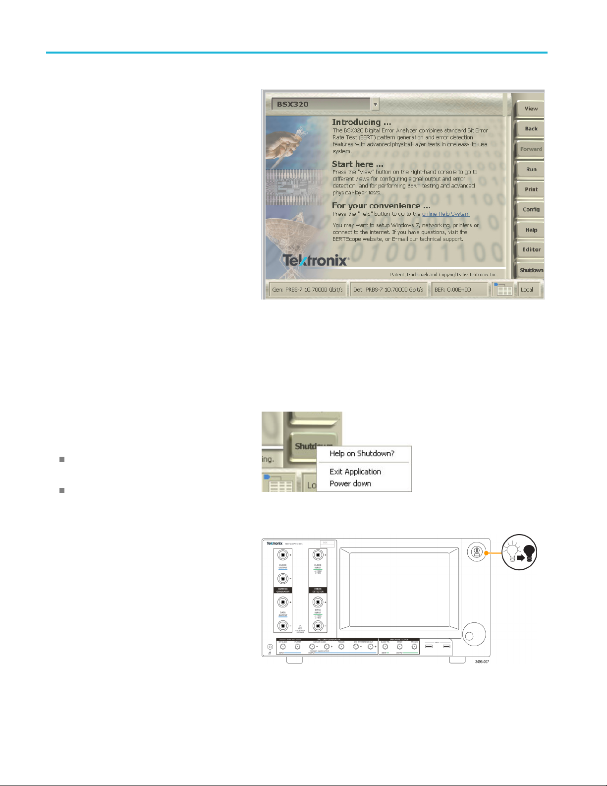
After the instrument completes the start-up sequence,
the Home view d
From the Home view, access other menus of the
instrument by touching the View button. The contents
of the list un
and configuration of your instrument.
UPDATE GRAPHIC WITH NEW SCREEN
isplays.
der the View menu depend on the options
Power off the instrument
Use the Shutdown button to exit the BERTScope application before powering
off the instrument.
1. Touch Shutdown on the lower-right side of the
.
screen
2. Do one of the following:
Select Power down to close the BERTScope
application and power off the instrument.
Select Exit Application to close the
cope application and access the
BERTS
computer desktop.
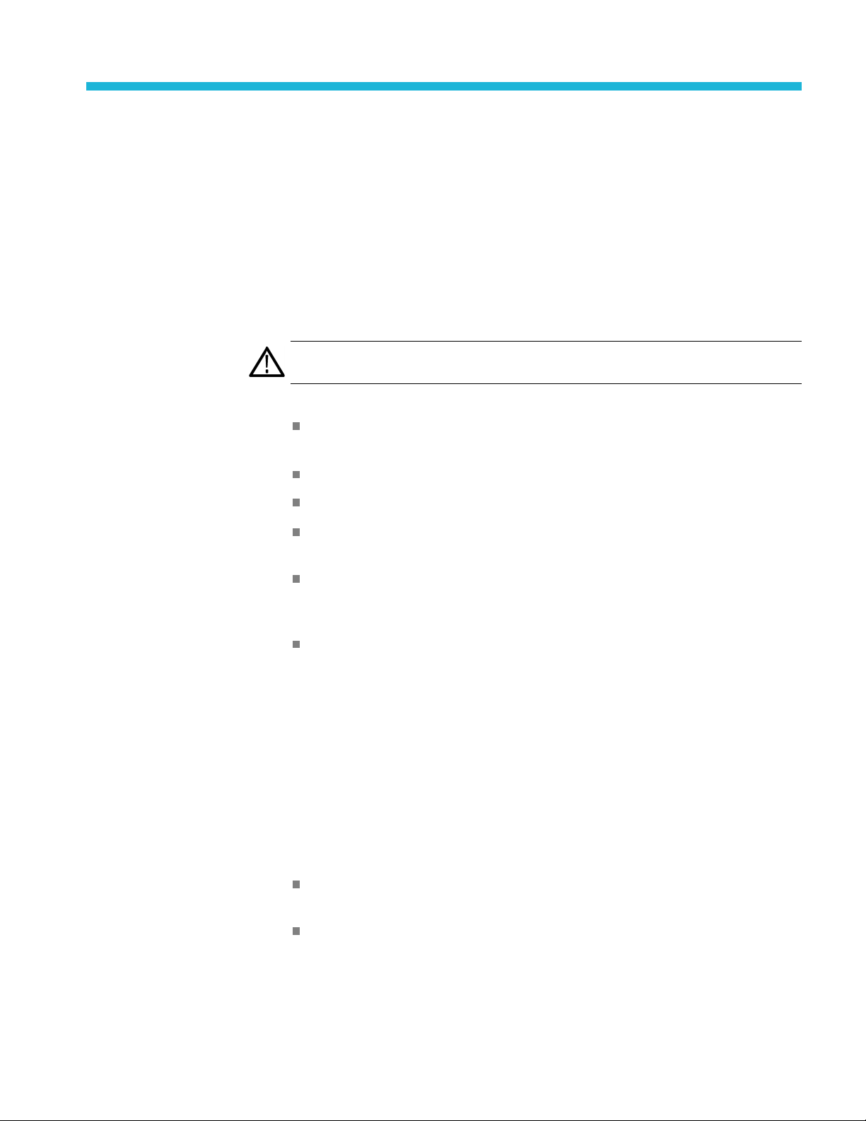
3. To power off the instrument from the computer
desktop, close any active applications and then
h the front panel power button.
pus
The green power indicator on the button will turn
off and the instrument will begin the shut down
cess.
pro
4 BSX Series Installation & Safety Instructions
Page 19

4. Disconnect the power cord from the rear of the
instrument to
instrument after it shuts down.
completely remove power from the
Installation
BSX Series Installation & Safety Instructions 5
Page 20

Installation
6 BSX Series Installation & Safety Instructions
Page 21

Controls and connectors
This section provides a high-level description of the control and connectors on
the instrument.
Front panel controls and connectors
The following fi gure and table describe common front panel controls and
connector
s.
e 1: Front panel
Figur
Table 4: Common front panel controls and connectors
Connector Description
1Display
2 Power switch Activates the power supply to provide power to the primary circuits in the instrument. The switch has a
3
4
5
Control knob Use the multifunction knob in stead of directly entering values to control items in the display such as
SB
U
Ground
connector
TFT touchscreen display to set up, control, and view information in the menus.
green light when power is turned on.
primary power control c ircuitry is always live whenever the power cord is connected to the
The
instrument. To completely disconnect power from the instrument, disconnect the power cord at
the rear of the instrument.
ving the cursor, scaling inputs, changing stress or amplitude levels, and scrolling data.
mo
se the USB connectors for connecting USB devices such as a mouse, keyboard, or USB flash drive.
U
Four additional USB connectors are located on the back of the instrument.
se this connector to connect a common ground to other instruments.
U
BSX Series Installation & Safety Instructions 7
Page 22

Controls and connectors
Pattern Generator
connectors
The following fi
connectors.
Figure 2: Pattern Generator front panel connectors
Table 5: Pattern Generator front panel connectors
Connector Description
1
2DATA
3
4HFJITTER
5
6
7
CLOCK
OUTPUT
Clock Output connectors. Use the differential connectors to output a clock signal from the Pattern
Generator. (Amplitude range: 250 mV to 1.8 V
Data Output connectors. Use the differential connectors to output data from the Pattern Generator.
OUTPUT
(Amplitude range: 50 mV to 1.8 V
EXT CLOCK External clock input connector. Use this input to connect an external clock source to the BERTScope
analzyer; (maximum input amplitude of +10 dBm or 2 V
High-frequency jitter insertion input connector. Use this connector to add external high-frequency jitter
(DC to 1 GHz) to the instrument with up to 0.5% UI. Apply signals up to 16 dBm (4 V
SUBRATE
CLOCK
Pattern Generator Subrate clock output connectors. The signal available at these differential output
connectors depend on the settings in the Generator view. Select SUBRATE to produce a Pattern
Generator clock or a submultiple of the clock without any added jitter (useful for measuring any
jitter that was added to the Pattern Generator output). Select STRESS to produce a version of the
Pattern Generator clock including any added jitter.
TRIGGER Pattern Generator trigger output connector. Use this connector to synchronize external equipment,
such as an oscilloscope to the BERTScope analyzer.
SINE
INTERFERENCE
OUT
Sine Interference output connectors. The signals at these output connectors provide the summed
differential output of two i nternal interference channel sources. In-phase and out-of-phase interference
can be output, or with the GUI selection, two independent single-ended tones are available.
gure and table describe the Pattern Generator front panel
).
p-p
, each leg).
p-p
).
p-p
) if needed.
p-p
8 BSX Series Installation & Safety Instructions
Page 23

Controls and connectors
Error Detector connectors
The following fi
(outlined in green).
Figure 3: Error Detector front panel connectors
Table 6: Error Detector front panel connectors
gure and table describe the Error Detector front panel connectors
Connector Description
1
2 DATA INPUT
3 BLANK Error Blank input connector. Use this connector to accept a TTL-level signal to cause the Error
4
5
CLOCK
INPUT
ERROR
TRIGGER
Error Detector clock input connector. Use this connector to provide a s ingle-ended clock input to the
Error Detector. The input frequency range depends on the instrument model. (Amplitude range: –3 V
to +4 V, 50 Ω, AC-coupled)
Error Detector data input connectors. Use the Data+ and Data– connectors to input differential data
signals to the Error Detector. (Amplitude range: –3 V to +4 V, 50 Ω, AC-coupled)
Detector to ignore errors. The Error Detector will ignore errors while this signal is active.
Error output connector. Use this connector to provide a 1000 mV pulse when an error is detected.
The m inimum pulse width is 128 serial clock periods.
Trigger output connector. Use this connector to synchronize external equipment, such as an
oscilloscope to the BERTScope analyzer.
BSX Series Installation & Safety Instructions 9
Page 24

Controls and connectors
Rear panel controls and connectors
The following figure and table describe the rear panel power and communication
connectors.
Figure 4: Rear panel connectors
Table 7: Rear panel power and communications connectors
Connector Description
1
2 IEEE4888
3
4
5
6
AC power Connect a suitable power cord to match the local power outlet type.
GPIB connector.
USB Four USB connectors (two additional connectors are located on the front of the instrument). Connect
USB devices such as keyboard, mouse, or USB flash drive.
VIDEO Monitor/display connector. Connect an external VGA display device.
LAN
SERIAL Reserved for future use.
Connect the instrument to a network for remote control operation, file sharing, and other network
operations.
10 BSX Series Installation & Safety Instructions
Page 25

Controls and connectors
The following fi
Figure 5: Rear panel BNC connectors
Table 8: Rear panel BNC connectors
Connect
1
2
3
4MARKE
5
6
7
8REFIN
9 LF JIT IN
or
PAT STAR
PAGE SEL Page Select. When enabled in the Pattern Sequencer, this input will cause the Pattern Sequencer to
DET ST
REF
LF SIN OUT Low-Frequency Sine Jitter Out. Use this connector to track the internal sine jitter modulation
REF+ OUT Reference Output (+). Use this connector with the (–) connector to provide a differential reference
T
ART
RIN
-OUT
Descrip
Pattern
data streams from multiple instruments.
advance to the next state depending upon the TTL level of the input signal. In legacy Page A/Page
B mode,
tor Start Input. Use this input to synchronize the E rror Detector with external equipment.
Detec
(LVTTL logic level, >1 kΩ into 0 V)
tor Marker input connector. Use this connector to accept a TTL-level Marker signal. The signal
Detec
can be used to synchronize error analysis with low-speed reference signals, such as mechanical
frequencies, packet boundaries, or loop markers. The minimum pulse width is 128 clock periods with
imum repetition rate of 512 serial clock periods.
amax
erence Output (–). Use this connector with the (+) connector to provide a differential reference
Ref
frequency for other instruments (typically 100 MHz). For single-ended applications, use the (+)
connector.
equency. It can be used to ensure that two BERTScope analyzers are both in-phase or
fr
out-of-phase.
frequency for other instruments (typically 100 MHz).
Reference Input. Use this connector to provide an input reference signal (amplitude: –6 dBm to
6 dBm). When the Synthesizer clock mode is selected, the fixed reference clock frequencies are:
+
10, 100, 106.25, 133.33, 165.25, 166.67, and 200 MHz. When the Reference Clock Multiplier (RCM)
mode is selected, the input frequency can be any frequency between 10 MHz and 200 MHz.
Low Frequency Jitter In. Use this connector to add external low frequency jitter (DC to 80 MHz) to
the instrument. The maximum signal level for this connector for normal operation is + 10 dBm (2 V
gure and table describe the rear panel BNC connectors.
tion
Start input. Use this input connector to simultaneously synchronize the patterns of multiple
a logic 0 selects Page A; and logic 1 selects Page B
).
p-p
BSX Series Installation & Safety Instructions 11
Page 26

Controls and connectors
12 BSX Series Installation & Safety Instructions
Page 27
Cleaning and maintenance
Periodic cleaning reduces instrument breakdown and increases reliability. Clean
the instrument as needed, based on the operating environment. Dirty conditions
may require m
Clean the flat panel display
ore frequent cleaning than computer room conditions.
The flat pan
during cleaning.
CAUTION. Improper cleaning agents or methods can damage the flat panel
display.
Do not use abrasive clea ners or commercial glass cleaners to clean the display
surface.
Do not spray liquids directly on the display surface.
Do not scrub the display with excessive force.
Avoid
only enough solution to dampen the wipe.
Clea
cleanroom wipe (such as Wypall Medium Duty Wipes, #05701, available
from Kimberly-Clark Corporation).
If the display is very dirty, moisten the wipe with distilled water or a 75%
isopropyl alcohol solution and gently rub the display surface. Avoid using
excess force or you may damage the plastic display surface.
el display is a soft plastic display and must be treated with care
getting moisture inside the instrument while cleaning the display; use
ntheflat panel display surface by gently rubbing the display with a
Clean the exterior surfaces
Clean the exterior surfaces with a dry, lint-free cloth or a soft-bristle brush. If dirt
remains, use a cloth or swab dampened with a 75% isopropyl alcohol solution. A
swab is useful for cleaning in narrow spaces around the controls and connectors.
Do not use abrasive compounds on any part of the instrument.
To avoid damaging the instrument follow these precautions:
Avoid getting moisture inside the instrument during external cleaning and use
only enough solution to dampen the cloth or swab.
Do not wash the front-panel power switch. Cover the switch while washing
the instrument.
BSX Series Installation & Safety Instructions 13
Page 28

Cleaning and maintenance
Use only deioni
solution as a cleanser and rinse with deionized water.
Do not use chem
chemicals that contain benzene, toluene, xylene, acetone, or similar solve nts.
zed water when cleaning. Use a 75% isopropyl alcohol
ical cleaning agents; they may damage the instrument. Avoid
14 BSX Series Installation & Safety Instructions
Page 29

Compliance information
This section lists the EMC (electromagnetic compliance), safety, and
environmental standards with which the instrument complies.
EMC compliance
Meets intent of Directive 2014/30/EU for Electromagnetic Compatibility.
Complianc
Official Journal of the European Communities:
e was demonstrated to the following speci fi cations as listed in the
EN 61326-1. EMC requirements for electrical equipment for measurement,
control, and laboratory use.
12
CISPR 11. Radiated and conducted emissions, Group 1, Class A
IEC 61000-4-2. Electrostatic discharge immunity
IEC 61000-4-3. RF electromagnetic field immunity
IEC 610
00-4-4. Electrical fast transient / burst immunity
IEC 61000-4-5. Power line surge immunity
IEC 61000-4-6. Conducted RF immunity
IEC 61000-4-11. Voltage dips and interruptions immunity
EN 61000-3-2. AC power line harmonic emissions
EN 61000-3-3. Voltage c hanges, fluctuations, and flicker
Compliance Contact
Tektronix, Inc. PO Box 500, MS 19‐045
Beaverton, OR 97077, USA
www.tek.com
1
This product is intended for use in nonresidential areas only. Use in residential areas may cause electromagnetic
interference.
2
Emissions which exceed the levels required by this standard may occur when this equipment is connected to a
test object.
ustralia / New Zealand
A
Complies with the EMC provision of the Radiocommunications Act per the
following standard, in accordance with ACMA:
BSX Series Installation & Safety Instructions 15
Page 30

Compliance information
Safety compliance
European Union
U.S. nationally recognized
testing laboratory listing
Canadian certification
CISPR 11. Radia
accordance with EN 61326-1.
This section lists the safety standards with which the product complies and other
safety compliance information.
Compliance was demonstrated to the following specification as listed in the
Official Journal of the European Union:
Low Voltage Directive 2014/35/EU.
EN 61010-1. Safety Requirements for Electrical Equipment for Measurement,
Control, and Laboratory Use – Part 1: General Requirements.
UL 61010-1. Safety Requirements for Electrical Equipment for Measurement,
Control, and Laboratory Use – Part 1: General Requirements.
CAN/CSA-C22.2 No. 61010-1. Safety Requirements for Electrical
Equipment for Measurement, Control, and Laboratory Use – Part 1: General
Requirements.
ted and Conducted Emissions, Group 1, Class A, in
Additional compliances
Equipment type
Safety class
Pollution degree
descriptions
IEC 61010-1. Safety Requirements for Electrical Equipment for
Measurement, Control, and Laborat ory Use – Part 1: General Requireme nts.
Test and measuring equipment.
Class 1 – grounded product.
A measure of the contaminants that could occur in the environment around
and within a product. Typically the internal environment inside a product is
considered to be the same as the external. Products should be used only in the
environment for which they are rated.
Pollution degree 1. No pollution or only dry, nonconductive pollution occurs.
Products in this category are generally encapsulated, hermetically sealed, or
located in clean rooms.
Pollution degree 2. Normally only dry, nonconductive pollution occurs.
Occasionally a temporary conductivity that is caused by condensation must
be expected. This location is a typical office/home environment. Temporary
condensation occurs only when the product is out of service.
16 BSX Series Installation & Safety Instructions
Page 31

Compliance information
Pollution degree rating
Measurement and
overvoltage category
descriptions
Pollution degr
that becomes conductive due to condensation. These are sheltered locations
where neither temperature nor humidity is controlled. The area is protected
from direct sunshine, rain, or direct wind.
Pollution degree 4 . Pollution that generates persistent conductivity through
conductive dust, rain, or snow. Typical outdoor locations.
Pollution degree 2 (as defined in IEC 61010-1). Rated for indoor, dry location
use only.
Measurem
from one or more of the following categories (see specific ratings marked on
the product and in the manual).
NOTE. Only mains power supply circuits have an overvoltage category rating.
Only measurement circuits have a measurement category rating. Other circuits
within the product do not have either rating.
ent terminals on this product m ay be rated for measuring mains voltages
Category II. Circuits directly connected to the building wiring at utilization
points (socket outlets and similar points).
Category III. In the building wiring and distribution system.
ory IV. At the source of the electrical supply to the building.
Categ
ee 3. Conductive pollution, or dry, nonconductive pollution
Mains overvoltage
Overvoltage category II (as defined in IEC 61010-1).
category rating
Environmental considerations
This section provides information about the environmental impact of the product.
Product end-of-life
handling
Observe the following guidelines when recycling an instrument or component:
Perchlorate materials. This product contains one or more type CR lithium
batteries. According to the state of California, CR lithium batteries are
classified as perchlorate materials and require specia l handling. See
www.dtsc.ca.gov/hazardouswaste/perchlorate for additional information.
BSX Series Installation & Safety Instructions 17
Page 32

Compliance information
18 BSX Series Installation & Safety Instructions
Page 33

Index
C
clearance requirements, 1
clock input
Error Detector, 9
clock output
Pattern Generator, 8
connector
conventions, vii
s
Error Detector, 9
front panel, 7
Pattern Generator, 8
rear panel, 10, 11
D
put
data in
Error Detector, 9
data output
Pattern Generator, 8
detector start input
Error Detector, 11
mentation, vii
docu
E
electrostatic discharge, 2
error blank input
Error Detector, 9
Error Detector
clock input, 9
ata input, 9
d
detector start input, 11
error blank input, 9
error output, 9
front panel connectors, 9
marker input, 11
trigger output, 9
error output
Error Detector, 9
ESD, 2
external clock input
Pattern Generator, 8
F
front panel
connectors,
front panel connectors
Error Detector, 9
Pattern Generator, 8
fuse
specifications, 1
7
H
high-fre
Home view, 4
quency jitter input
Pattern Generator, 8
L
low-frequency sine jitter in
Pattern Generator, 11
low-frequency sine jitter out
rn Generator, 11
Patte
M
manual
conventions, vii
marker input
Error Detector, 11
O
online help, vii
perating requirements, 1
o
P
page select
Pattern Generator, 11
Pattern Generator
clock output, 8
data output, 8
external clock input, 8
front panel
high-frequency jitter input, 8
low-frequency sine jitter
in, 11
low-frequency sine jitter
out, 11
page sele
pattern start input, 11
reference in, 11
reference out, 11
sine interference outputs, 8
subrate clock output, 8
er output, 8
trigg
pattern start input
Pattern Generator, 11
power off procedure, 4
power on procedure, 3
power requirements, 1
connectors, 8
ct, 11
R
ar panel
re
BNC connectors, 11
connectors, 10
reference in
Pattern Generator, 11
reference out
Pattern Generator, 11
requirements
clearance, 1
power, 1
ventilation, 1
voltage, 1
S
self test, 3
shut down procedure, 4
sine interference outputs
Pattern Generator, 8
site considerations, 1
BSX Series Installation & Safety Instructions 19
Page 34

Index
specifications
fuse, 1
static precautions, 2
subrate clock output
Pattern Generator, 8
T
touch
defined, vi
i
trigger output
Error Detector, 9
Pattern Generator, 8
V
ventilation requirements, 1
VGA connector, 10
view
defined, vi
i
voltage
requirements, 1
20 BSX Series Installation & Safety Instructions
 Loading...