

Page 1
xx
Overview
Use this document to get your BERTScope hardware
connected and the software and drivers installed. The
instrument front-panel connections for a typical USB test
setup are shown at the end of the procedures.
The following procedures should be done in the order they
are presented:
1.
Make the USB connections.
2.
Make the Ethernet connections.
3.
Load and configure the oscilloscope software.
4.
Load and configure the BERTScope software
(download the latest BERTScope software from
www.tektronix.com).
5.
Load and configure the USB Automation software on
your PC (this software can instead be loaded on the
oscilloscope or BERTScope, but is not recommended).
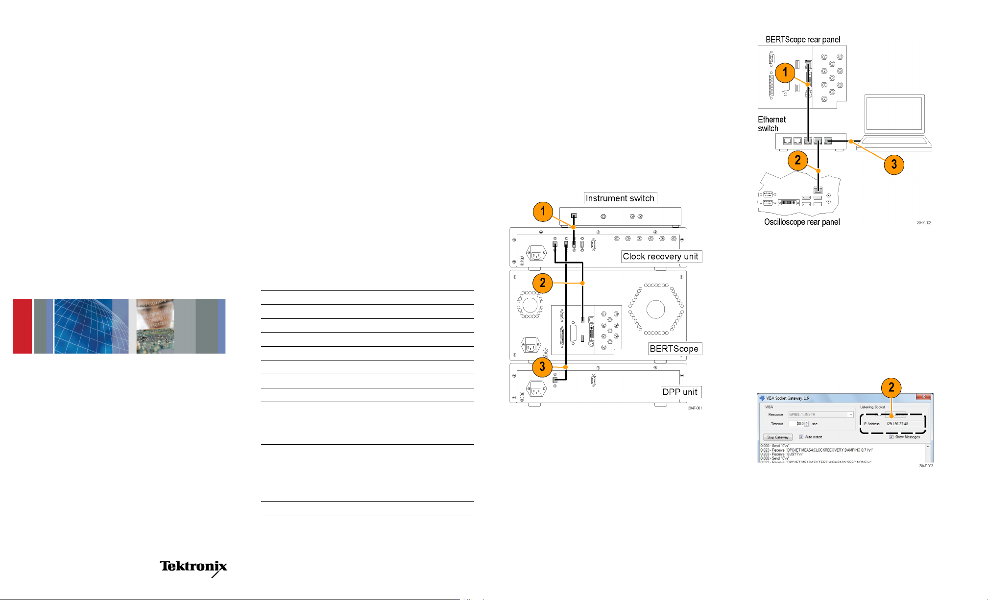
Make the USB Connections
This setup uses the Clock Recovery Unit as the USB
hub. Using 3 USB A–B cables, make the following USB
connections on the rear panels of the equipment:
1.
Insert the B end of a USB cable into the Instrument
Switch. Connect the other end of the cable into any
USB-A connector on the Clock Recovery Unit.
2.
Insert the B end of a USB cable into the USB-B
connector on the Clock Recovery Unit. Connect the
other end of the cable into the BERTScope.
3.
Insert the B end of a USB cable into the DPP Unit.
Connect the other end of the cable into any USB-A
connector on the Clock Recovery Unit.
BSAUSB
USB Receiver Testing Application
ZZZ
Installation Instructions
*P071304701*
071-3047-01
x
Required Equipment
You need the equipment and software listed below to
complete these procedures.
BSASWITCH Tektronix Instrument Switch
CR125A Clock Recovery Unit (or equivalent)
DPP125 Digital Pre-emphasis Processor unit
BSA BERTScope C model, with option SF and STR installed
DPO/DSA/MSO71604C or above oscilloscope
Ethernet switch,10/100 Mbps minimum
(3) Ethernet cables
(3) USB cables, A–B, (standard accessories with the equipment)
USB Receiver Testing Application software (downloadable
from www.tektronix.com); includes switch control software and
drivers, control panel and socket server, manual, BSAUSB31,
BSAUSB3, and BSASWITCH.
SigTest tool (application software downloadable from USB.org;
search SigTest tool)
(Recommended) PC w/Windows XP, Vista, or Windows 7 OS.
Note: Although the BERTScope or oscilloscope can be used as
the controller instead of a PC, it is not recommended.
(Optional) USB Receiver Testing MOI
Make the Ethernet Connections
The setup described here uses an Ethernet switch, but you
can use your internal Ethernet network instead. Using 3
Ethernet cables, make the following Ethernet connections
on the rear panels of the equipment:
1.
Insert an Ethernet cable into the Ethernet Switch.
Connect the other end of the cable into the BERTScope.
2.
Insert another Ethernet cable into the Ethernet Switch.
Connect the other end of the cable into the oscilloscope.
3.
Insert a third Ethernet cable into the Ethernet Switch.
Connect the other end of the cable into the Ethernet
port on your computer.
Load and Configure the Software and Drivers
The BERTScope and oscilloscope must be loaded with
application software. The USB Automation software should
be loaded on a separate PC.
Oscilloscope Software
1.
Load Visa Socket Gateway on the oscilloscope. This
software must be running on the oscilloscope to allow
communication between the instruments.
2.
Record the IP address; it is used later in the Windows
PC Software procedure.
3.
Load the SigTest application software on the
oscilloscope.
4.
Load the SigTest Server software on the oscilloscope.
This software must be running on the oscilloscope to
allow communication to the SigTest application.
5.
Record the IP address of the SigTest application; it is
used later in the Windows PC Software procedure.
Page 2

BERTScope Software
1.
Power on the Clock Recovery unit, BERTScope, and
instrument switch, but do not power on the DPP until
after the BERTScope Main Window displays.
2.
Install the Switch Control Software on the BERTScope.
The installation package is on the software disk.
The Switch Control Software must be running on
the BERTScope to allow communication with the
Instrument Switch.
The Switch Control window displays “Connected
to:” when it connects to the Instrument Switch.
3.
Enable the Remote Client on the BERTScope:
a.
Click start > Programs > BERTScope > Remote
Client.
b.
Select TCP-IP.
c.
Record the IP address; it is used later in the
Windows PC Software setup procedure.
Windows PC Software
For best system performance, load the USB Automation
Software on an external PC or laptop computer.
1.
Install the USB Automation Software on t he PC.
Check with your Tektronix Sales Representative for
NOTE.
any later versions of the USB Automation Software.
2.
Once installed, open the application and click
Preferences > Equipment.
3.
Open the window for each instrument and enter the IP
address as instructed in steps 4 and 5.
4.
Enter the BERTScope IP address in the Address fields
for both the BERTScope and for the Switch.
5.
Enter the oscilloscope IP address in the Address fields
for both the oscilloscope and SigTest server.
6.
Click Start Connect. The Start Connect window
appears.
Typical Test Setup
The SuperSpeed signal connections for a typical USB test
setup are shown. For details about the fixtures, adapters,
and other equipment required for this setup, see your user
manual. The manual also includes information about setting
up and using other test configurations.
7.
Click Connect for all four entries. The red tabs at the
bottom of the window change to green when connected.
8.
If the BERTScope is being used for the first time for
USB testing, check all of the boxes for the data pattern
files in the lower half of the Start Connect window,
and then click Download.
Copyright © Tektronix, Inc. All rights reserved. www.tektronix.com
 Loading...