

Page 1

User Manual
BG1
Black Burst Generator
070-9298-01
This document supports software version 2.0 and
above.
Page 2

Copyright T ektronix, Inc. All rights reserved.
T ektronix products are covered by U.S. and foreign patents, issued and pending. Information in this publication supercedes
that in all previously published material. Specifications and price change privileges reserved.
Printed in the U.S.A.
T ektronix, Inc., P.O. Box 1000, Wilsonville, OR 97070–1000
TEKTRONIX and TEK are registered trademarks of T ektronix, Inc.
Page 3

WARRANTY
T ektronix warrants that the products that it manufactures and sells will be free from defects in materials and workmanship
for a period of one (1) year from the date of shipment. If a product proves defective during this warranty period, T ektronix,
at its option, either will repair the defective product without charge for parts and labor, or will provide a replacement in
exchange for the defective product.
In order to obtain service under this warranty, Customer must notify Tektronix of the defect before the expiration of the
warranty period and make suitable arrangements for the performance of service. Customer shall be responsible for
packaging and shipping the defective product to the service center designated by T ektronix, with shipping charges prepaid.
T ektronix shall pay for the return of the product to Customer if the shipment is to a location within the country in which the
T ektronix service center is located. Customer shall be responsible for paying all shipping charges, duties, taxes, and any
other charges for products returned to any other locations.
This warranty shall not apply to any defect, failure or damage caused by improper use or improper or inadequate
maintenance and care. T ektronix shall not be obligated to furnish service under this warranty a) to repair damage resulting
from attempts by personnel other than T ektronix representatives to install, repair or service the product; b) to repair
damage resulting from improper use or connection to incompatible equipment; c) to repair any damage or malfunction
caused by the use of non-T ektronix supplies; or d) to service a product that has been modified or integrated with other
products when the effect of such modification or integration increases the time or difficulty of servicing the product.
THIS WARRANTY IS GIVEN BY TEKTRONIX IN LIEU OF ANY OTHER WARRANTIES, EXPRESS OR
IMPLIED. TEKTRONIX AND ITS VENDORS DISCLAIM ANY IMPLIED WARRANTIES OF
MERCHANTABILITY OR FITNESS FOR A PARTICULAR PURPOSE. TEKTRONIX’ RESPONSIBILITY TO
REP AIR OR REPLACE DEFECTIVE PRODUCTS IS THE SOLE AND EXCLUSIVE REMEDY PROVIDED TO
THE CUSTOMER FOR BREACH OF THIS WARRANTY. TEKTRONIX AND ITS VENDORS WILL NOT BE
LIABLE FOR ANY INDIRECT , SPECIAL, INCIDENTAL, OR CONSEQUENTIAL DAMAGES IRRESPECTIVE
OF WHETHER TEKTRONIX OR THE VENDOR HAS ADVANCE NOTICE OF THE POSSIBILITY OF SUCH
DAMAGES.
Page 4

Service Assurance
If you have not already purchased Service Assurance for this product, you may do so at any time during the product’s
warranty period. Service Assurance provides Repair Protection and Calibration Services to meet your needs.
Repair Protection extends priority repair services beyond the product’s warranty period; you may purchase up to three
years of Repair Protection.
Calibration Services provide annual calibration of your product, standards compliance and required audit documentation,
recall assurance, and reminder notification of scheduled calibration. Coverage begins upon registration; you may purchase
up to five years of Calibration Services.
Service Assurance Advantages
Priced well below the cost of a single repair or calibration
Avoid delays for service by eliminating the need for separate purchase authorizations from your company
Eliminates unexpected service expenses
For Information and Ordering
For more information or to order Service Assurance, contact your T ektronix representative and provide the information
below . Service Assurance may not be available in locations outside the United States of America.
Name VISA or Master Card number and expiration
Company date or purchase order number
Address Repair Protection (1,2, or 3 years)
City , State, Postal code Calibration Services (1,2,3,4, or 5 years)
Country Instrument model and serial number
Phone Instrument purchase date
Page 5

Table of Contents
Getting Started
Operating Basics
General Safety Summary v. . . . . . . . . . . . . . . . . . . . . . . . . . . . . . . . . . . .
Service Safety Summary vii. . . . . . . . . . . . . . . . . . . . . . . . . . . . . . . . . . . . .
Preface ix. . . . . . . . . . . . . . . . . . . . . . . . . . . . . . . . . . . . . . . . . . . . . . . . . . .
About This Manual ix. . . . . . . . . . . . . . . . . . . . . . . . . . . . . . . . . . . . . . . . . . . . . . .
Related Manuals ix. . . . . . . . . . . . . . . . . . . . . . . . . . . . . . . . . . . . . . . . . . . . . . . . . .
Contacting T ektronix x. . . . . . . . . . . . . . . . . . . . . . . . . . . . . . . . . . . . . . . . . . . . . .
Getting Started 1–1. . . . . . . . . . . . . . . . . . . . . . . . . . . . . . . . . . . . . . . . . . . .
Accessories 1–2. . . . . . . . . . . . . . . . . . . . . . . . . . . . . . . . . . . . . . . . . . . . . . . . . . . . . .
Configuration 1–2. . . . . . . . . . . . . . . . . . . . . . . . . . . . . . . . . . . . . . . . . . . . . . . . . . . .
Installation 1–2. . . . . . . . . . . . . . . . . . . . . . . . . . . . . . . . . . . . . . . . . . . . . . . . . . . . . .
Functional Check 1–3. . . . . . . . . . . . . . . . . . . . . . . . . . . . . . . . . . . . . . . . . . . . . . . . .
Functional Overview 2–1. . . . . . . . . . . . . . . . . . . . . . . . . . . . . . . . . . . . . . . .
Outputs 2–2. . . . . . . . . . . . . . . . . . . . . . . . . . . . . . . . . . . . . . . . . . . . . . . . . . . . . . . . .
Online Help 2–2. . . . . . . . . . . . . . . . . . . . . . . . . . . . . . . . . . . . . . . . . . . . . . . . . . . . .
Operating Procedures 2–3. . . . . . . . . . . . . . . . . . . . . . . . . . . . . . . . . . . . . . .
Power On and Select the Module 2–4. . . . . . . . . . . . . . . . . . . . . . . . . . . . . . . . . . . . .
Select the Black Burst Output Signal 2–5. . . . . . . . . . . . . . . . . . . . . . . . . . . . . . . . . .
Module Parameters 2–7. . . . . . . . . . . . . . . . . . . . . . . . . . . . . . . . . . . . . . . . . . . . . . . .
Enable/Disable Black Burst Outputs 2–8. . . . . . . . . . . . . . . . . . . . . . . . . . . . . .
Enable/Disable Clock Output 2–8. . . . . . . . . . . . . . . . . . . . . . . . . . . . . . . . . . . .
Select Clock Output 2–9. . . . . . . . . . . . . . . . . . . . . . . . . . . . . . . . . . . . . . . . . . .
Setting a New Clock Frequency 2–10. . . . . . . . . . . . . . . . . . . . . . . . . . . . . . . . . .
Clock Allocation 2–11. . . . . . . . . . . . . . . . . . . . . . . . . . . . . . . . . . . . . . . . . . . . . .
Frame Reset Allocation 2–12. . . . . . . . . . . . . . . . . . . . . . . . . . . . . . . . . . . . . . . . .
Syntax
Syntax 3–1. . . . . . . . . . . . . . . . . . . . . . . . . . . . . . . . . . . . . . . . . . . . . . . . . . . .
Programming Model 3–1. . . . . . . . . . . . . . . . . . . . . . . . . . . . . . . . . . . . . . . . . . . . . .
Addressing Module T est Signals 3–1. . . . . . . . . . . . . . . . . . . . . . . . . . . . . . . . .
Command Arguments 3–1. . . . . . . . . . . . . . . . . . . . . . . . . . . . . . . . . . . . . . . . . .
Argument Example 3–2. . . . . . . . . . . . . . . . . . . . . . . . . . . . . . . . . . . . . . . . . . . .
SCPI Commands and Queries 3–3. . . . . . . . . . . . . . . . . . . . . . . . . . . . . . . . . . . . . . .
Functional Command Groups 3–5. . . . . . . . . . . . . . . . . . . . . . . . . . . . . . . .
MMemory 3–5. . . . . . . . . . . . . . . . . . . . . . . . . . . . . . . . . . . . . . . . . . . . . . . . . . . . . .
Output 3–6. . . . . . . . . . . . . . . . . . . . . . . . . . . . . . . . . . . . . . . . . . . . . . . . . . . . . . . . . .
Source 3–6. . . . . . . . . . . . . . . . . . . . . . . . . . . . . . . . . . . . . . . . . . . . . . . . . . . . . . . . . .
:OUTPut Commands 3–7. . . . . . . . . . . . . . . . . . . . . . . . . . . . . . . . . . . . . . .
Command Tree 3–7. . . . . . . . . . . . . . . . . . . . . . . . . . . . . . . . . . . . . . . . . . . . . . . . . . .
:OUTPut:STATe(?) 3–8. . . . . . . . . . . . . . . . . . . . . . . . . . . . . . . . . . . . . . . . . . . . . . . .
:OUTPut:CLOCk:STATe(?) 3–9. . . . . . . . . . . . . . . . . . . . . . . . . . . . . . . . . . . . . . . . .
BG1 Black Burst Generator User Manual
i
Page 6

Table of Contents
Appendices
Glossary and Index
:SOURce Commands 3–11. . . . . . . . . . . . . . . . . . . . . . . . . . . . . . . . . . . . . . . .
Command Tree 3–11. . . . . . . . . . . . . . . . . . . . . . . . . . . . . . . . . . . . . . . . . . . . . . . . . . .
:SOURce:CLOCk:FREQuency(?) 3–12. . . . . . . . . . . . . . . . . . . . . . . . . . . . . . . . . . . .
:SOURce:CLOCk:FREQuency:STEP 3–13. . . . . . . . . . . . . . . . . . . . . . . . . . . . . . . . .
:SOURce:CLOCk:SOURce(?) 3–14. . . . . . . . . . . . . . . . . . . . . . . . . . . . . . . . . . . . . . .
Appendix A: Specifications A–1. . . . . . . . . . . . . . . . . . . . . . . . . . . . . . . . . . .
Certifications A–2. . . . . . . . . . . . . . . . . . . . . . . . . . . . . . . . . . . . . . . . . . . . . . . . . . . .
Standards Conformance A–2. . . . . . . . . . . . . . . . . . . . . . . . . . . . . . . . . . . . . . . . . . . .
Appendix B: SCPI Conformance Information B–1. . . . . . . . . . . . . . . . . . .
Appendix C: Installation C–1. . . . . . . . . . . . . . . . . . . . . . . . . . . . . . . . . . . . .
Preventing Component Damage C–1. . . . . . . . . . . . . . . . . . . . . . . . . . . . . . . . . . . . .
Module Installation C–2. . . . . . . . . . . . . . . . . . . . . . . . . . . . . . . . . . . . . . . . . . . . . . .
Module Removal C–7. . . . . . . . . . . . . . . . . . . . . . . . . . . . . . . . . . . . . . . . . . . . . . . . .
ii
BG1 Black Burst Generator User Manual
Page 7

List of Figures
Table of Contents
Figure 2–1: Basic menu structure for the BG1 Generator module 2–1. .
Figure 3–1: Example of SCPI subsystem hierarchy tree 3–3. . . . . . . . . . .
Figure C–1: TG 2000 Platform mainframe rear panel, showing slot
numbering C–2. . . . . . . . . . . . . . . . . . . . . . . . . . . . . . . . . . . . . . . . . . . . .
Figure C–2: Top cover removal C–3. . . . . . . . . . . . . . . . . . . . . . . . . . . . . . .
Figure C–3: Rear panel removal C–4. . . . . . . . . . . . . . . . . . . . . . . . . . . . . .
Figure C–4: Module flange C–4. . . . . . . . . . . . . . . . . . . . . . . . . . . . . . . . . . .
Figure C–5: Module installation C–5. . . . . . . . . . . . . . . . . . . . . . . . . . . . . .
Figure C–6: Top screw C–6. . . . . . . . . . . . . . . . . . . . . . . . . . . . . . . . . . . . . .
BG1 Black Burst Generator User Manual
iii
Page 8

Table of Contents
List of Tables
Table 1–1: Standard and optional accessories 1–2. . . . . . . . . . . . . . . . . . .
Table 3–1: :MMEMory commands 3–5. . . . . . . . . . . . . . . . . . . . . . . . . . . .
Table 3–2: :OUTPut commands 3–6. . . . . . . . . . . . . . . . . . . . . . . . . . . . . .
Table 3–3: :SOURce commands 3–6. . . . . . . . . . . . . . . . . . . . . . . . . . . . . .
Table A–1: Electrical specifications A–1. . . . . . . . . . . . . . . . . . . . . . . . . . .
Table A–2: Certifications and compliances A–2. . . . . . . . . . . . . . . . . . . . .
Table B–1: SCPI 1994.0 conformance information B–1. . . . . . . . . . . . . . .
Table C–1: Module slot assignments C–2. . . . . . . . . . . . . . . . . . . . . . . . . . .
iv
BG1 Black Burst Generator User Manual
Page 9

General Safety Summary
Review the following safety precautions to avoid injury and prevent damage to
this product or any products connected to it.
Only qualified personnel should perform service procedures.
To avoid potential hazards, use this product only as specified.
Injury Precautions
Product Damage
Precautions
Symbols and Terms
Avoid Electric Overload. To avoid electric shock or fire hazard, do not apply a
voltage to a terminal that is outside the range specified for that terminal.
Do Not Operate With Suspected Failures. If you suspect there is damage to this
product, have it inspected by qualified service personnel.
T erms in this Manual. These terms may appear in this manual:
WARNING. Warning statements identify conditions or practices that could result
in injury or loss of life.
CAUTION. Caution statements identify conditions or practices that could result in
damage to this product or other property.
T erms on the Product. These terms may appear on the product:
DANGER indicates an injury hazard immediately accessible as you read the
marking.
WARNING indicates an injury hazard not immediately accessible as you read the
marking.
CAUTION indicates a hazard to property including the product.
Symbols on the Product. The following symbols may appear on the product:
DANGER
High Voltage
BG1 Black Burst Generator User Manual
Protective Ground
(Earth) T erminal
ATTENTION
Refer to Manual
Double
Insulated
v
Page 10

General Safety Summary
Certifications and
Compliances
Refer to the specifications section for a listing of certifications and compliances
that apply to this product.
vi
BG1 Black Burst Generator User Manual
Page 11

Service Safety Summary
Only qualified personnel should perform service procedures. Read this Service
Safety Summary and the General Safety Summary before performing any service
procedures.
Do Not Service Alone. Do not perform internal service or adjustments of this
product unless another person capable of rendering first aid and resuscitation is
present.
Disconnect Power. To avoid electric shock, disconnect the main power by means
of the power cord or, if provided, the power switch.
Use Care When Servicing With Power On. Dangerous voltages or currents may
exist in this product. Disconnect power, remove battery (if applicable), and
disconnect test leads before removing protective panels, soldering, or replacing
components.
To avoid electric shock, do not touch exposed connections.
BG1 Black Burst Generator User Manual
vii
Page 12

Service Safety Summary
viii
BG1 Black Burst Generator User Manual
Page 13

Preface
About This Manual
This manual documents the capabilities, specifications, operation, and installation of the BG1 Generator module.
This manual is composed of the following sections:
Getting Started provides a product description, standard and optional
accessories list, and an incoming inspection procedure.
Operating Basics describes the windowed menu interface and how to control
the module through the interface in conjunction with the front-panel
controls.
Syntax and Commands defines the syntax used in command descriptions,
presents a list of all command subsystems, and presents detailed descriptions
of all programming commands.
Appendices provides additional information including the electrical
specifications, compliances, and hardware installation procedures.
Related Manuals
The following documents are also available:
The BG1 Black Burst Generator Service Manual describes how to service
the module. This optional manual must be ordered separately.
The TG 2000 Signal Generation Platform User Manual describes how to use
the TG 2000 Platform. It also contains information about SCPI commands,
programming structure, and status and events for the platform. Some of this
information applies to all generator modules, including the DVG1 Generator
module. This manual is a standard accessary to the TG 2000 Platform
mainframe.
The TG 2000 Signal Generation Platform Service Manual describes how to
service the mainframe to the module level and provides general information
about servicing generator modules. This optional manual must be ordered
separately.
A module user manual is included with each optional module. Contact your
Tektronix representative for a list of generator and special function modules.
BG1 Black Burst Generator User Manual
ix
Page 14

Preface
Contacting Tektronix
Product
Support
Service
Support
For other
information
To write us Tektronix, Inc.
For application-oriented questions about a Tektronix measurement product, call toll free in North America:
1-800-TEK-WIDE (1-800-835-9433 ext. 2400)
6:00 a.m. – 5:00 p.m. Pacific time
Or, contact us by e-mail:
tm_app_supp@tek.com
For product support outside of North America, contact your
local Tektronix distributor or sales office.
Contact your local Tektronix distributor or sales office. Or, visit
our web site for a listing of worldwide service locations.
http://www.tek.com
In North America:
1-800-TEK-WIDE (1-800-835-9433)
An operator will direct your call.
P.O. Box 1000
Wilsonville, OR 97070-1000
x
BG1 Black Burst Generator User Manual
Page 15

Getting Started
Page 16

Page 17

Getting Started
The BG1 Generator module is a multiple-format black burst generator. The
module can supply one of the six following black burst signals on the three
rear-panel output connectors:
NTSC with setup and no color frame reference
NTSC with setup and color frame reference
NTSC without setup
NTSC without setup and with color frame reference
PAL with color frame reference
PAL without color frame reference
You can select the rear-panel Clock Out signal from the following signals:
The 27 MHz master clock
Two Direct Digital Synthesis (DDS) clocks, which you can set from 10 MHz
to 100 MHz
Two frame reset pulses
The timing of the outputs is time zero for reference timing. The output timing
cannot be delayed.
The BG1 Generator module is supplied as a standard accessory with the
TG 2000 Signal Generation Platform.
NOTE. If the black burst or clock outputs are not required, the BG1 Generator
module can be removed to provide a mainframe slot for another module.
BG1 Black Burst Generator User Manual
1–1
Page 18

Getting Started
Accessories
Table 1–1 lists the standard and optional accessories for the module. Standard
accessories are included with the module, and optional accessories are available
for purchase to use with the module.
T able 1–1: Standard and optional accessories
Accessory Typo of accessory Part number
BG1 Black Burst Generator User Manual Standard 070-9298-XX
T-10 Torx Tip Standard 003-1604-XX
Screws (2 ea) Standard 211-0725-XX
Blank rear panel Standard 333-41 13-00
BG1 Black Burst Generator Service Manual Optional 070-9304-XX
Configuration
Installation
The module does not require any hardware configuration. You cannot reconfigure the signal outputs.
The module should be installed by qualified service personnel only. Refer to
Appendix C for detailed instructions on how to install the module.
The module is shipped with the signal sets already installed. You cannot change
the signals or signal sets for this module. (The SDP2000 Signal Development
Program cannot create signals for the BG1 Generator module.) However, you can
use an AVG1 Generator module to generate similar signals.
1–2
BG1 Black Burst Generator User Manual
Page 19

Functional Check
Getting Started
This procedure determines if your module is operating correctly. If you are not
familiar with the operation of the module, it may be helpful to refer to Figure
2–1 on page 2–1 while performing this procedure.
Required Equipment
Procedure
For this procedure, you will need a television monitor and a frequency counter or
an oscilloscope.
To check your module, follow these steps:
1. If the module is not installed in the TG 2000 Platform mainframe, install the
module, using the installation procedures beginning on page C–2.
2. Power on the TG 2000 Signal Generation Platform. The platform runs a self
test on all modules.
3. To determine if the self test was successful, press the Modules button.
Check the display for the icon that represents the BG1 Generator module.
4. Push the Modules button and touch the BG1 icon on the display.
5. Select either the NTSC or the PAL signal set.
6. Select Black Burst (the black burst signal without color frame reference).
7. Connect the BG1 Generator module Output 1 signal to the television
monitor.
8. Set the monitor to the pulse-cross setting so that you can see the signal
blanking areas.
9. Select Black Burst + Frm Ref (the black burst signal with color frame
reference).
10. Check that the color frame reference signal appears as expected.
11. For NTSC users only, push the Signal Sets button, and then select the
NTSC no Setup signal set. Select a signal and check that the signal
displayed on the monitor changes appropriately.
12. Connect the Output 2 signal to the monitor. Check that the signal that was on
Output 1 appears on Output 2.
13. Repeat step 12 for Output 3.
14. Connect the Clock Out signal to the frequency counter or oscilloscope.
15. From the Test Signals window, touch Module Parameters.
16. Touch Clock Out.
BG1 Black Burst Generator User Manual
1–3
Page 20

Getting Started
17. Touch Clock Out.
18. Change the clock frequency using either of these methods:
Turn the front-panel Navigation knob
Enter the value on the front-panel keypad and press Enter.
19. Check the frequency counter or the oscilloscope to be sure that the measured
frequency changes accordingly.
1–4
BG1 Black Burst Generator User Manual
Page 21

Operating Basics
Page 22

Page 23
Functional Overview
This section provides an overview of the BG1 Generator module. If you are not
familiar with the operation of the TG 2000 Signal Generation Platform, refer to
the TG 2000 Signal Generation Platform User Manual before reading this
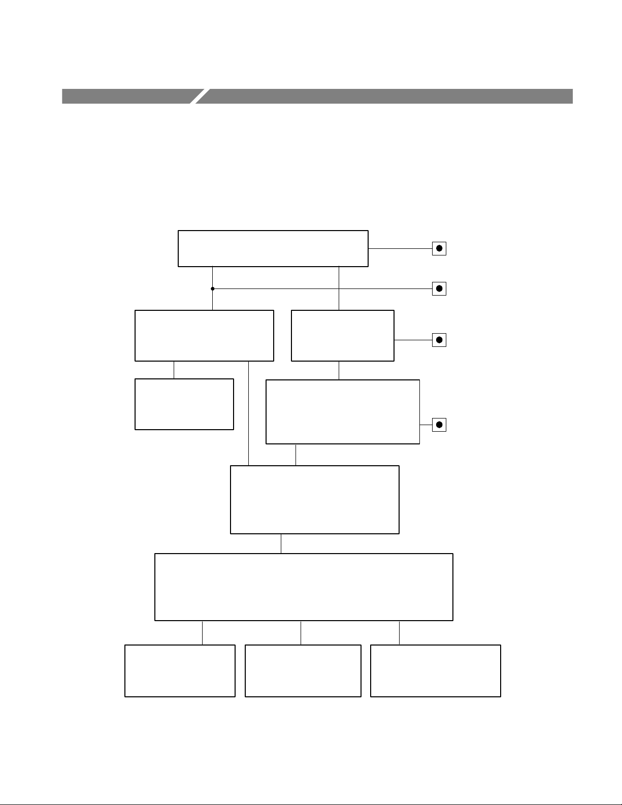
section. Figure 2–1 shows the menu structure for basic module operations.
Edit Module window
Touch Rename
Module
Rename Module window
Enter new name for
module
Modules window
Touch Module
Parameters
Touch Clock Out
Touch BG1 module
Signal Sets window
Touch desired signal set
(usually represents format)
Test Signals window
Touch Module
Parameters
Module Parameters window
Touch desired signal icon
to select output signal
Touch Output to
enable or disable the
module output signal
Push Modules
button
Push Edit button
Push Signal
Sets button
Push Test
Signals button
Clock Out window
Touch any clock or frame reset to select it as the Clock Out signal.
Touch New Clock Touch Clock Clients Touch Frame Reset Clients
Clock Allocation windowNew Clock window Frame Reset Allocation window
View a list of modules that
Enter a new clock frequency.
are clients of each clock.
Figure 2–1: Basic menu structure for the BG1 Generator module
BG1 Black Burst Generator User Manual
View a list of modules that are
clients of each frame reset.
2–1
Page 24

Functional Overview
Outputs
Online Help
The BG1 Generator module has four outputs: a clock output and three black
burst signal outputs. All four outputs have standard BNC connectors.
Push the front-panel HELP button to display a help window. The help window
describes the window you were using when you pushed HELP.
If a help window is longer than the display, you can scroll through the help text
using the Navigation arrow keys. To exit the help window, touch Quit.
2–2
BG1 Black Burst Generator User Manual
Page 25

Operating Procedures
This section is divided into the following basic topics:
Power on the mainframe and select the module
Select the black burst signal
Module parameters
Refer to Figure 2–1 on page 2–1 for information on how to access the appropriate window for these procedures.
BG1 Black Burst Generator User Manual
2–3
Page 26

Operating Procedures
Power On and Select the Module
After the module is installed in the mainframe, and the mainframe is installed in
the rack or other location where it will be used, power on the mainframe and
select the module by following these steps:
1. Set the rear-panel power switch to the ON position.
2. Press the front-panel POWER switch if necessary.
3. Wait for a few seconds as the mainframe executes confidence tests on the
mainframe and modules. Check for any error messages that might appear.
4. When self tests are complete, check for an icon representing each installed
generator module. After each module name is an area that can be used to
indicate the slot number in which it is installed. If an installed module is not
represented, refer to Troubleshooting in the TG 2000 Signal Generation
Platform Service Manual.
5. Since you have just powered on the mainframe, the Modules window (shown
below) is displayed. To select the module at other times, push the front-panel
Modules button to access this window.
2–4
6. Touch the BG1 icon on the display (or push the Signal Sets button if the
BG1 icon is already highlighted). The installed signal sets for the module
appear. Selections you make after this will pertain to the BG1 Generator
module.
BG1 Black Burst Generator User Manual
Page 27

Select the Black Burst Output Signal
The black burst signal is supplied on three rear-panel outputs labeled Output 1,
Output 2, and Output 3. To select the output signal, follow these steps:
1. Select the BG1 Generator module.
2. Push the Signal Sets button.
3. In the BG1 Signal Sets window (shown below) touch the desired signal set
on the display. (In this example, NTSC is selected.)
Operating Procedures
4. The Test Signals window for the selected signal set appears, as shown in the
following illustration. In this example, the Black Burst signal is active.
Change to another signal by touching the signal icon.
BG1 Black Burst Generator User Manual
2–5
Page 28

Operating Procedures
5. You can also select the output signal using the List window as follows:
a. Push the front-panel List button to display the list of test signals.
b. Use the Navigation arrow keys to highlight the module and signal
c. Push the Select button.
2–6
BG1 Black Burst Generator User Manual
Page 29

Module Parameters
Operating Procedures
The following procedures discuss windows that are accessed through the Module
Parameters window, shown below. Changes that you make to parameters in any
of these windows affect the entire module.
To enter the Module Parameters window for the BG1 Generator module, follow
these steps:
1. Select the BG1 Generator module if not already selected.
2. Push the Test Signals button.
3. Touch Module Parameters at the bottom of the screen. The Module
Parameters window is shown below.
4. Another way to access this window is as follows:
a. Push the Modules button.
b. Ensure that the module is highlighted.
c. Push the Edit button.
d. Touch Module Parameters.
BG1 Black Burst Generator User Manual
2–7
Page 30

Operating Procedures
Enable/Disable Black
Burst Outputs
Enable/Disable Clock
Output
When you disable the black burst outputs, the platform’s clock and frame reset
resources used by the BG1 Generator module are released. Disabling the black
burst outputs does not disable the BG1 Generator module clock output.
To enable or disable the outputs, follow these steps:
1. In the Module Parameters window, shown on page 2–7, touch Output to
enable or disable the Black Burst outputs (rear-panel Output 1, Output 2, and
Output 3).
2. Touch Quit to exit.
When you disable the clock, the platform’s clock resource used by the clock
output is released. Disabling the clock output does not disable the black burst
outputs (rear-panel Output 1, Output 2, and Output 3). To disable or enable the
clock output, follow these steps:
1. In the Module Parameters window, shown on page 2–7, touch Clock Out.
The Clock Out window is shown on page 2–10.
2. To disable the clock output, touch Disable Clock Out.
3. To enable the clock output again, select one of the displayed signals.
4. Touch Quit to exit.
2–8
BG1 Black Burst Generator User Manual
Page 31

Operating Procedures
Select Clock Output
You can select the signal that is sent to the rear-panel Clock Out connector. You
cannot select an unassigned resource as the output signal. To select the clock
output, follow these steps:
1. In the Module Parameters window, shown on page 2–7, touch Clock Out.
2. In the Clock Out window, shown below, select the clock output signal by
touching the desired signal on the display. The signals are:
Fixed clock (27 MHz)
Variable clock 1
Variable clock 2
Frame reset 1
Frame reset 2
BG1 Black Burst Generator User Manual
2–9
Page 32

Operating Procedures
Setting a New Clock
Frequency
You can be set a new clock frequency to any frequency between 10 MHz and
100 MHz. The clock signal frequency that you select is sent to the rear-panel
clock output.
To set the clock frequency, follow these steps:
1. In the Module Parameters window, shown on page 2–7, touch Clock Out.
The Clock Out window is shown on page 2–10.
2. In the Clock Out window, touch New Clock.
3. Set the frequency using either of these methods:
Rotate the Navigation knob (counterclockwise to decrease frequency and
clockwise to increase frequency).
Enter a frequency value from the front-panel keypad and push the
front-panel Select button.
Setting the clock to a frequency other than 27 MHz uses one of the platform’s two variable clocks, depending on which one is available. If neither
of the variable clocks is available, the clock allocation window appears. This
provides you the chance to disable one of the clocks.
4. Touch Quit to return to the Clock Out window. Check that the new
frequency appears, and is selected as the output signal.
2–10
BG1 Black Burst Generator User Manual
Page 33

Operating Procedures
Clock Allocation
A clock client is a module that uses the specified clock. When you disable clock
clients, you free up the clock resources. To disable clock clients, follow these
steps:
1. In the Module Parameters window, shown on page 2–7, touch Clock Out.
The Clock Out window is shown on page 2–10.
2. In the Clock Out window, touch Clock Clients. The Clock Allocation
window opens, as shown below. This window is also displayed if you
attempt to use or define a clock when insufficient clock resources are
available. If this occurs, you must disable some of the module clients before
continuing.
3. The Clock Allocation window displays a list of all clients for each clock. In
the example, the AWVG1 module is using variable clock 1 which is set for
72 MHz, and the BG1 module is using variable clock 2 which is set for 10
MHz.
Touch Disable above the list of clock clients that you want to disable. To
exit without disabling any clients, touch Cancel.
4. To recover the clock clients, enable the module outputs as follows:
a. Push the Modules button and select the module you want to enable.
b. Push the Test Signals button.
c. Touch Module Parameters.
d. Touch Output to enable the output.
e. Touch Quit to exit.
BG1 Black Burst Generator User Manual
2–11
Page 34

Operating Procedures
Frame Reset Allocation
There are two frame reset pulses, Frame 1 and Frame 2. A frame reset client is a
module that uses the specified frame reset pulse. When you disable frame reset
clients, you free up the frame reset resources. To disable frame reset clients,
follow these steps:
1. In the Module Parameters window, shown on page 2–7, touch Clock Out.
The Clock Out window is shown on page 2–10.
2. In the Clock Out window, touch Frame Reset Clients. The Frame Reset Al-
location window opens, as shown below. This window is also displayed if
you attempt to use a frame reset when insufficient resources are available. If
this occurs, you must disable some of the module clients before continuing.
2–12
3. The Frame Reset Allocation window displays a list of all clients for each
frame reset pulse. In the example, the BG1, DVG1, AWVG1 and AVG1
modules are using frame reset 1 which is set for 14.985 Hz. Frame 2 is
unused.
a. Touch Disable above the list of frame reset clients that you want to
disable.
b. To exit without disabling any clients, touch Cancel.
4. To recover the frame reset clients, enable the module outputs as follows:
a. Push the Modules button and select the module you want to enable.
b. Push the Test Signals button.
c. Touch Module Parameters.
d. Touch Output to enable the output.
e. Touch Quit to exit.
BG1 Black Burst Generator User Manual
Page 35

Syntax
Page 36

Page 37

Syntax
Programming Model
This section contains information on the Standard Commands for Programmable
Instruments (SCPI) and the programming structure you can use to program your
module.
Programming commands address specific modules and must conform to the
proper syntax to achieve the desired result.
Addressing Module Test
Signals
Command Arguments
The following two steps must be performed before the test module will respond
to signal parameter commands:
1. Select the module to be addressed before executing any commands. Many of
the commands used by this module are shared by several modules and will
be accepted without a reported error.
2. Enable the module using the command. The output state
of the module must be enabled before test-signal parameters can be changed.
Many commands will accept either string or numeric arguments. For example, a
Boolean argument can either be “1” or “ON”.
Signal parameter commands that have a :STEP node can accept either a numeric
value or they can accept a string argument that refers to the :STEP increment.
Signal parameter commands with a :STEP node will accept the following strings
in addition to a numeric value:
UP. Use this argument to increase the parameter value one increment as defined
by the :STEP value.
DOWN. Use this argument to decrease the parameter value one increment as
defined by the :STEP value.
BG1 Black Burst Generator User Manual
3–1
Page 38

Syntax
MINimum. Use this argument to set the parameter value to the minimum
acceptable value.
MAXimum. Use this argument to set the parameter value to the maximum
acceptable value.
DEFault. Use this argument to set the parameter value to the default value.
Argument Example
The following example demonstrates the effect of arguments used with a step
value.
1. :INSTrument:SELect "AVG1:#" selects the analog video generator module
located in the slot number indicated by the “#” symbol.
2. :OUTPut:STATe ON enables the module and displays the loaded test signal.
3. :OUTPut:CIRCle:STATe ON displays a circle on the video display.
NOTE. :OUTPut:CIRCle:DIAMeter uses an argument that is the percent of
picture height.
4. :OUTPut:CIRCle:DIAMeter DEFault sets the circle diameter to 90 percent
of the screen height.
5. :OUTPut:CIRCle:DIAMeter:STEP 10 sets the step increment to 10 percent.
6. :OUTPut:CIRCle:DIAMeter DOWN changes the circle diameter to 80 percent
of the screen height.
7. :OUTPut:CIRCle:DIAMeter 50 changes the circle diameter to 50 percent of
the screen height.
3–2
8. :OUTPut:CIRCle:DIAMeter MAXimum changes the circle diameter to
100 percent of the screen height.
9. :OUTPut:CIRCle:DIAMeter MINimum changes the circle diameter to
0 percent of the screen height.
10. :OUTPut:CIRCle:DIAMeter UP changes the circle diameter to 10 percent of
the screen height.
BG1 Black Burst Generator User Manual
Page 39

SCPI Commands and Queries
SCPI is a standard created by a consortium that provides guidelines for remote
programming of instruments. These guidelines provide a consistent programming environment for instrument control and data transfer. This environment
uses defined programming messages, instrument responses, and data format
across all SCPI instruments, regardless of manufacturer. The TG 2000 generator
uses a command language based on the SCPI standard.
The SCPI language is based on a hierarchical or tree structure (see Figure 3–1)
that represents a subsystem. The top level of the tree is the root node; it is
followed by one or more lower-level nodes.
Syntax
OUTPut
CIRCle
DIAMeter
POSitionSTATe
Root node
Lower-level
nodes
Figure 3–1: Example of SCPI subsystem hierarchy tree
You can create commands and queries from these subsystem hierarchy trees.
Commands specify actions for the instrument to perform. Queries return
measurement data and information about parameter settings.
For more information on SCPI commands, programming structure, and system
status and events, refer to the TG 2000 User Manual.
BG1 Black Burst Generator User Manual
3–3
Page 40

Syntax
3–4
BG1 Black Burst Generator User Manual
Page 41

Functional Command Groups
This section describes the commands in general categories. Commands to the
module are divided into the following groups:
MMEMory (see TG 2000 Signal Generation Platform User Manual)
OUTPut
SOURce
Items followed by question marks are queries; items without question marks are
commands. Some items in this section have a question mark in parentheses (?) in
the command header section; this indicates that the item can be both a command
and a query.
MMemory
Two MMEMory commands are listed here for your reference. You can use these
to set and query the output test signal for the module. Detailed information for
using these commands (as well as other commands that can be used with the
entire platform) are located in the TG 2000 Signal Generation Platform User
Manual.
T able 3–1: :MMEMory commands
Command Description
:MMEMory:LOAD:SIGNal Load a signal into a module and identify that signal as the active
signal (output signal) for that module
:MMEMory:SIGNal:ACTive? List the active signal (output signal) for a module
BG1 Black Burst Generator User Manual
3–5
Page 42

Functional Command Groups
Output
Use these commands to select the output characteristics of the module.
T able 3–2: :OUTPut commands
Command Description
:OUTPut:CLOCk:STATe(?) Set or query clock output
:OUTPut:STA Te(?) Set or query module output
Source
Use these commands to define the signal parameters for the module.
T able 3–3: :SOURce commands
Command Description
:SOURce:CLOCk:FREQuency(?) Set or query clock frequency
3–6
BG1 Black Burst Generator User Manual
Page 43

:OUTPut Commands
Use these commands to enable the actual output of the module. These commands
do not release any resources controlled by the signal manager or the clock
manager.
NOTE. The module must be selected with the INSTrument subsystem prior to
using these commands.
Command Tree
:OUTPut
:CLOCk
:STATe <Boolean>
:STATe <Boolean>
BG1 Black Burst Generator User Manual
3–7
Page 44

:OUTPut Commands
:OUTPut:STATe(?)
Use this command to set or query the state of the module’s output signal.
Syntax
Parameters
Default Value
Errors and Events
Dependencies
Examples
Related Commands
:OUTPut:STATe <Boolean>
:OUTPut:STATe?
Command Query response
<Boolean> = ON or 1, OFF or 0 1, 0
ON
None
None
Command: :OUTP:STAT ON
Query: :OUTP:STAT?
Response: 1
None
3–8
BG1 Black Burst Generator User Manual
Page 45

:OUTPut:CLOCk:STATe(?)
Use this command to set or query the state of the module’s clock output signal.
:OUTPut Commands
Syntax
Parameters
Default Value
Errors and Events
Dependencies
Examples
Related Commands
:OUTPut:CLOCk:STATe <Boolean>
:OUTPut:CLOCk:STATe?
Command Query response
<Boolean> = ON or 1, OFF or 0 1, 0
ON
None
None
Command: :OUTP:CLOC:STAT ON
Query: :OUTP:CLOC:STAT?
Response: 1
:SOURce:CLOCk:FREQuency
BG1 Black Burst Generator User Manual
3–9
Page 46

:OUTPut Commands
3–10
BG1 Black Burst Generator User Manual
Page 47

:SOURce Commands
Use this command to select the module’s clock frequency.
NOTE. The module must be selected with the INSTrument subsystem prior to
using this command.
Command Tree
:SOURce
:CLOCk
:FREQuency <numeric_value>
:SOURce <clock>
:STEP
BG1 Black Burst Generator User Manual
3–11
Page 48

:SOURce Commands
:SOURce:CLOCk:FREQuency(?)
Use this command to set or query the module’s clock frequency.
Syntax
Parameters
Default Value
Errors and Events
Dependencies
Examples
:SOURce:CLOCk:FREQuency <numeric_value>
:SOURce:CLOCk:FREQuency?
Command Query response
<numeric_value> = <NR3>
10000000.00Hzto100000000.00Hz
Not applicable
None
None
Command: :SOUR:CLOC:FREQ 14e6
Query: :SOUR:CLOC:FREQ?
Response: 14000000.0000
<NR2>
3–12
Related Commands
OUTPut:CLOCk:STATe
:SOURce:CLOCk:FREQuency:STEP
BG1 Black Burst Generator User Manual
Page 49

:SOURce:CLOCk:FREQuency:STEP
Use this command to set or query the UP/DOWN step value of the clock
frequency.
:SOURce Commands
Syntax
Parameters
Default Value
Errors and Events
Dependencies
Examples
:SOURce:CLOCk:FREQuency:STEP <numeric_value>
:SOURce:CLOCk:FREQuency:STEP?
Command Query response
<numeric_value> = <NRf>
MIN, MAX, DEF
1.0
–200 Execution error
None
Command: :SOURce:CLOCk:FREQ:STEP 2
Query: :SOURce:CLOCk:FREQ:STEP?
Response: Response: 2.0000
<NR2>
Related Commands
BG1 Black Burst Generator User Manual
:SOURce:CLOCk:FREQuency
3–13
Page 50

:SOURce Commands
:SOURce:CLOCk:SOURce(?)
Use this command to select the clock or frame source for the clock output of the
module.
Syntax
Parameters
Default Value
Errors and Events
Dependencies
Examples
:SOURce:CLOCk:SOURce <clock>
:SOURce:CLOCk:SOURce?
Command Query response
FCLOck
VCLOck1
VCLOck2
VFRAme1
VFRAme2
OFF
FCLO
VCLO1
VCLO2
VFRA1
VFRA2
OFF
Off
–200 Execution error
Earlier hardware versions of the module may not support the variable frame
selections. The actual frequency depends on the sequence of module startup.
Command: :SOUR:CLOC:SOUR vclo2
3–14
Related Commands
Query: :SOUR:CLOC:SOUR?
Response: vclo2
OUTPut:CLOCk:FREQuency
BG1 Black Burst Generator User Manual
Page 51

Appendices
Page 52

Page 53

Appendix A: Specifications
Table A–1 lists the Electrical specifications for the BG1 Generator module, and
and Table A–2 lists the EMC compliance specifications. Specifications are
guaranteed unless labeled “typical.” Typical specifications are provided for your
convenience, but are not guaranteed.
Specifications are valid only when the module is properly installed in a TG 2000
Signal Generation Platform.
Refer to the TG 2000 Signal Generation Platform User Manual for a list of
Environmental specifications.
T able A–1: Electrical specifications
Characteristics Description
Black Burst Outputs
Sync Amplitude Accuracy 2%. All rear panel outputs except clock output
Burst Amplitude Accuracy 5%. Relative to sync amplitude
SCH Phase Error, typical Phase error 5_
DC Offset 50 mV
Return Loss/Output Impedance 36 dB to 6 MHz. 75
Clock Output
Amplitude 0.4 V p-p 0.1 V. Into 75 , AC coupled,
Return Loss/Output Impedance, typical 15 dB 1 MHz to 100 MHz, 75
Frequency Range, typical 10 MHz to 100 MHz
Frequency Accuracy As displayed on front panel 1 ppm, when not
Nonharmonic Spurs, typical –45 dBc or better
Power Consumption, typical +5 Volts: 2.0 Watts typical
square wave
genlocked
–5 Volts: 1.1 Watts typical
–2 Volts: 0.3 Watts typical
+15 Volts: 0 Watts typical
–15 Volts: 0 Watts typical
Battery: 0 A typical
BG1 Black Burst Generator User Manual
A–1
Page 54

Appendix A: Specifications
Certifications
Standards Conformance
T able A–2: Certifications and compliances
Characteristics Description
EMC Compliance Meets the intent of Directive 89/336/EEC
for Electromagnetic Compatibility when it
is used with the product(s) stated in the
specifications table. Refer to the EMC
specification published for the stated products. May not meet the intent of the directive if used with other products.
FCC Compliance Emissions comply with FCC Code of Fed-
eral Regulations 47, Part 15, Subpart B,
Class A Limits
The BG1 Generator module conforms to the following standards:
EBU N14
SMPTE RP 154
A–2
BG1 Black Burst Generator User Manual
Page 55

Appendix B: SCPI Conformance Information
All commands in the BG1 Generator module are based on SCPI Version 1994.0.
Table B–1 lists all commands supported by the module. The columns at right
show whether or not a command is defined in the SCPI 1994.0 Standard.
T able B–1: SCPI 1994.0 conformance information
Command Defined in SCPI Not defined In SCPI
OUTPut CLOCk STATe(?) n
STATe(?) n
SOURce CLOCk FREQuency(?) n
STEP(?) n
SOURce(?) n
BG1 Black Burst Generator User Manual
B–1
Page 56

Appendix B: SCPI Conformance Information
B–2
BG1 Black Burst Generator User Manual
Page 57

WARNING
The following servicing instructions are for use only by qualified personnel. To
avoid injury, do not perform any servicing other than that stated in the operating
instructions unless you are qualified to do so. Refer to all Safety Summaries before
performing any service.
Page 58

Page 59

Appendix C: Installation
This section contains instructions for installing the module into the
TG 2000 Platform mainframe.
Preventing Component Damage
CAUTION. Electrostatic discharge (ESD) can damage components on this module
and mainframe. To prevent ESD or other component damage, follow the steps
below when installing, removing, or handling modules:
1. Wear a grounded antistatic wrist strap to discharge the static voltage from
your body while installing or removing modules from the TG 2000 Platform
mainframe.
2. Transport and store modules in a static-protected bag or container.
3. Do not slide the module over any surface.
4. Handle modules as little as possible.
5. Do not touch module components or connector pins.
6. Do not use any devices capable of generating or holding a static charge in the
work area where you remove, install, or handle modules.
7. Avoid handling modules in areas that have a floor or work-surface covering
capable of generating a static charge.
8. Do not remove the module circuit board assembly from the shield. The
shield provides important support and protection for the surface-mount
components.
BG1 Black Burst Generator User Manual
C–1
Page 60

Appendix C: Installation
Module Installation
A T-10 torx tip screwdriver is the only tool you need to install the module. A
T-10 torx tip is supplied with the module.
To install the module into the TG 2000 Platform mainframe, perform these steps:
1. Set the TG 2000 Platform mainframe rear-panel power switch to off.
2. Unplug the power cord.
3. Select the slot you will use to install the module. Table C–1 lists the slot
restrictions. Figure C–1 shows a sample configuration with slot numbers.
T able C–1: Module slot assignments
Module Slots in which the module can be installed
AGL1 Genlock module Slot 2 or 3
AVG1 Generator module Slots 2 through 10
AWVG1 Generator module Slots 2 through 10
BG1 Generator module Slot 2 through 10
Clock module Slot 1
CPU module Slot 11
DVG1 Generator module Slots 2 through 10
GP1 GPIB Interface module Slot 10
Power
Supply
CPU
Module
GPIB
Module
AVG1
Module
DVG1
Module
AWVG1
Module
AGL1
Module
Module
Clock
Module
BG1
C–2
11
10987654321
Figure C–1: TG 2000 Platform mainframe rear panel, showing slot numbering
BG1 Black Burst Generator User Manual
Page 61

Appendix C: Installation
WARNING. To avoid a shock hazard, always remove the power cord before
removing the top cover. Failure to remove the power cord can result in serious
injury or death.
4. Refer to Figure C–2 and remove or loosen all screws to remove the top
cover.
Top cover
Loosen screws (12)
Top cover
Remove
screws
(23)
Figure C–2: Top cover removal
BG1 Black Burst Generator User Manual
C–3
Page 62

Appendix C: Installation
5. Remove the appropriate rear panel as shown in Figure C–3. Loosen, but do
not remove the bottom screw. You will use it later to secure the module.
Loosen screw
Figure C–3: Rear panel removal
6. While ensuring correct alignment of the module flange as shown in
Figure C–4, lower the module into the desired slot as shown in Figure C–5.
Flange
C–4
Figure C–4: Module flange
BG1 Black Burst Generator User Manual
Page 63

Insert screw
Appendix C: Installation
Tighten screw
Figure C–5: Module Installation
7. Ensure that the connectors on the Backplane board and the module exactly
match before seating the module.
CAUTION. The connectors must exactly match before you attempt to press the
module firmly in place. If the connectors do not match, you might bend a pin that
could damage the module, mainframe, or both when power is applied.
8. Press down evenly on the module until it is firmly in place.
9. Insert and tighten the top screw, supplied with your module, as shown in
Figure C–6.
10. Tighten the rear panel screw.
BG1 Black Burst Generator User Manual
C–5
Page 64

Appendix C: Installation
Figure C–6: Top screw
11. Replace the top cover.
12. Insert and tighten all top cover screws.
13. Plug in the instrument power cord. Power on the mainframe by setting the
rear-panel power switch to ON and pressing the front-panel power switch.
14. Wait for the instrument to perform self tests.
C–6
BG1 Black Burst Generator User Manual
Page 65

Module Removal
Appendix C: Installation
Before removing any of the generator modules that allow you to load signals,
such as the AVG1 Generator module and the DVG1 Generator module, you
should save the signal sets to a disk. Refer to the module’s user manual for
instructions on backing up the signal sets. However, you do not need to back up
the BG1 Generator module signals because they are not lost when the module is
removed from the platform.
To remove the module, follow these steps:
1. Turn off the platform by pressing the front-panel On/Standby switch and
switching the rear panel power switch to off.
2. Unplug the power cord.
WARNING. To avoid a shock hazard, always unplug the power cord before
removing the top cover. Failure to unplug the power cord can result in serious
injury or death.
3. Remove all top-cover screws and remove the top cover. See Figure C–2 on
page C–3.
4. Remove the appropriate rear panel as shown in Figure C–3 on page C–4.
Loosen, but do not remove the bottom screw. You will use it later to secure
the rear panel.
5. Refer to Figure C–6 on page C–6 and remove the top screw.
6. Remove the module. To leave the slot empty, proceed to step 8 of this
procedure.
7. To install a module in the empty slot, proceed to Module Installation on
page C–2.
8. To ensure proper cooling and adherence to EMI shielding requirements,
install a blank panel to cover any empty slots in the rear panel. A spare blank
panel is included in the TG 2000 Platform mainframe accessories kit.
9. Tighten the screws on the blank rear panel.
10. Reinstall the top cover and insert and tighten all top cover screws.
BG1 Black Burst Generator User Manual
C–7
Page 66

Appendix C: Installation
C–8
BG1 Black Burst Generator User Manual
Page 67

Glossary and Index
Page 68

Page 69

Glossary
Black Burst
Also called “color black,” black burst is a composite video signal consisting
of all horizontal and vertical synchronization information and burst.
Typically used as the house reference synchronization signal in television
facilities.
Burst
A small reference packet of the subcarrier sine wave sent on every line of
video. Since the carrier is suppressed, this phase and frequency reference is
required for synchronous demodulation of the color difference signals in the
receiver.
Color Frame Reference Flag
The color frame reference flag is the white flag that can be selected to be on
the black burst signals of the BG1 module. The flag occurs on field 1,
line 10 for the NTSC and NTSC without setup test signals. The flag occurs
on field 1, line 7 for the PAL test signals.
Composite Video
A single video signal containing all of the necessary information to
reproduce a color picture. Created by adding quadrature amplitude modulated U and V to the luminance signal.
Frame
A frame (sometimes called a “picture”) contains all the information required
for a complete picture. For interlaced scan systems, there are two fields in a
frame.
NTSC
National Television System Committee. The organization that developed the
television standard currently in use in the United States, Canada and Japan.
Now generally used to refer to that standard.
PAL
Phase Alternate Line. Refers to one of the television systems used in Europe
and many other parts of the world. The phase of one of the color difference
signals alternates from line to line to help cancel out phase errors.
SCPI
Standard Commands for Programmable Instruments. SCPI is a standard that
provides guidelines for remote programming of instruments. These
guidelines provide a consistent programming environment for instrument
control and data transfer.
BG1 Black Burst Generator User Manual
Glossary–1
Page 70

Glossary
Signal Set
A set of industry standard test signals provided by Tektronix on floppy disks.
Soft key
An item on the display that changes state or initiates an action when you
touch it on screen. You use soft keys to select test signals or enter a file
name.
Termination
In order to accurately send a signal through a transmission line, there must
be an impedance at the end that matches the impedance of the source and of
the line itself. Amplitude errors and reflections will otherwise result. Video
is a 75 W system, so a 75 W terminator must be put at the end of the signal
path.
Time Zero
Time zero is the reference time for the TG 2000 mainframe and is the timing
of the outputs of the BG1 module. When you adjust the Genlock module
timing, you are adjusting the time zero reference. When you adjust the
timing of an individual module, the timing of that module is offset from the
time zero reference.
Glossary–2
BG1 Black Burst Generator User Manual
Page 71

Index
A
Accessories
optional, 2
standard, 2
B
BG1, features, 1
Black burst output, enable, 2–8
Black burst outputs, 2–5
Black burst signals, 1
C
Clock allocation window, 2–11
Clock out, frequency, 2–10
Clock Out window, 2–10
Clock output, 1
enable, 2–8
Color frame reference, 1
Command groups, 3–5
Commands
arguments, 3–1
rules for forming, 3–1
syntax, 3–1
Configuration, 2
D
H
Hierarchy Tree, 3–3
I
Inspection, Functional Check, 3
Installation, 1
M
Menu structure, 1
Module parameters window, 2–7
Module removal, 7
Modules window, 2–4
N
New clock window, 2–10
O
Online help, 2
Operating procedures, 2–3
Optional accessories, 2
Output commands, 3–6, 3–7
Output signal, 2–5
Output timing, 1
Outputs, 2
Disable black burst output, 2–8
Disable clock output, 2–8
E
Electrical specifications, A–1
Enable black burst outputs, 2–8
Enable clock output, 2–8
F
Frame reset allocation, 2–12
Frequency , clock, 2–10
Functional check, 3
Functional overview, 1
BG1 Black Burst Generator User Manual
P
Power on procedure, 2–4
R
Rear-panel connectors, 2
Remote, loading a signal, 3–5
Removing a module, 7
Rules, command forming, 3–1
S
Saving signal sets, when removing other modules, 7
Index–1
Page 72

Index
SCPI, subsystem hierarchy tree, 3–3
SCPI commands
output, 3–6, 3–7
queries syntax, 3–3
source, 3–6, 3–11
SCPI conformance, B–1
Select clock output, 2–9
Select output signal, 2–5
Select the module, 2–4
Signal, black burst, 1
Signal set installation, 2
Signal Sets window, 2–5
Signals, BG1, 1
Source commands, 3–6, 3–11
Specifications
electrical, A–1
SCPI conformance, B–1
standards conformance, A–2
Standard accessories, 2
Standards conformance, A–2
Syntax, command, 3–1
System clocks, 1
T
T est signals window, 2–6
Time zero, 1
Timing, output, 1
W
Window
clock allocation, 2–11
clock out, 2–10
frame reset allocation, 2–12
module parameters, 2–7
modules, 2–4
new clock, 2–10
signal sets, 2–5
test signals, 2–5
Index–2
BG1 Black Burst Generator User Manual
Page 73

Page 74

 Loading...