


x
Tektronix BERTScope
Bit Error Rate Analyzers
BSA85C, BSA125C, BSA175C, BSA260C, BSA286C
ZZZ
Quick Start User Manual
*P071286903*
071-2869-03


xx
Tektronix BERTScope
Bit Error Rate Analyzers
BSA85C, BSA125C, BSA175C, BSA260C, BSA286C
ZZZ
Quick Start User Manual
www.tektronix.com
071-2869-03

Copyright © Tektronix. All rights reserved. Licensed software products are owned by Tektronix or its subsidiaries or suppliers, and are
protected by na
tional copyright laws and international treaty provisions.
Tektronix pro
previously published material. Specifications and price c hange privileges reserved.
TEKTRONIX and TEK are registered trademarks of Tektronix, Inc.
ducts are covered by U.S. and foreign patents, issued and pending. Information in this publication supersedes that in all
Contacting Tektronix
Tektronix, Inc.
14150 SW Karl Braun Drive
P.O. Box 500
Beaverton, OR 97077
USA
For product information, sales, service, and technical support:
In North America, call 1-800-833-9200.
Worldwide, visit www.tektronix.com to find contacts in your area.

Warranty
Tektronix warrants that this product will be free from defects in materials and workmanship for a period of one (1) year from the date of
shipment. If any such product proves defective during this warranty period, Tektronix, at its option, either will repair the defective
product without charge for parts and labor, or will provide a replacement in exchange for the defective product. Parts, modules and
replacement products used by Tektronix for warranty work may be new or reconditioned to like new performance. All replaced
parts, modules and products become the property of Tektronix.
In order to obtain service under this warranty, Customer must notify Tektronix of the defect before the expiration of the warranty period
and make suitable arrangements for the performance of service. Customer shall be responsible for packaging and shipping the
defective product to the service center designated by Tektronix, with shipping charges prepaid. Tektronix shall pay for the return of the
product to Customer if the shipment is to a location within the country in which the Tektronix service center is located. Customer shall
be responsible for paying all shipping charges, duties, taxes, and any other charges for products returned to any other locations.
This warranty shall not apply to any defect, failure or damage caused by improper use or improper or inadequate m aintenance and
care. Tektronix shall not be obligated to furnish service under this warranty a) to repair damage resulting from attempts by personnel
other than Tektronix representatives to install, repair or service the product; b) to repair damage resulting from improper use or
connection to incompatible equipment; c) to repair any damage or malfunction caused by the use of non-Tektronix supplies; or
d) to service a product that has been modified or integrated with other products when the effect of such modification or integration
increases the time or difficulty of servicing the product.
THIS WARRANTY IS GIVEN BY TEKTRONIX WITH RESPECT TO THE PRODUCT IN LIEU OF ANY OTHER WARRANTIES,
EXPRESS OR IMPLIED. TEKTRONIX AND ITS VENDORS DISCLAIM ANY IMPLIED WARRANTIES OF MERCHANTABILITY OR
FITNESS FOR A PARTICULAR PURPOSE. TEKTRONIX' RESPONSIBILITY TO REPAIR OR REPLACE DEFECTIVE PRODUCTS
IS THE SOLE AND E XCLU S IVE REMEDY PROVIDED TO THE CUSTOMER FOR BREACH OF THIS WARRANTY. TEKTRONIX
AND ITS VENDORS WILL NOT BE LIABLE FOR ANY INDIRECT, SPECIAL, INCIDENTAL, OR CONSEQUENTIAL DAMAGES
IRRESPECTIVE OF WHETHER TEKTRONIX OR THE VENDOR HAS ADVANCE NOTICE OF THE POSSIBILITY OF SUCH
DAMAGES.
[W2 – 15AUG04]


Table of Contents
General safety summary ..... . . . . . ..... . . . . . ....... . . . . ..... . . . . . ....... . . . . ..... . . . . . ...... . . . . . ...... . . . . ...... . . . . . ..... . . . . . ...... iii
Compliance information ............................................................................................................... v
EMC compliance................................................................................................................. v
Safety compliance................................................................................................................vi
Environmentalconsiderations ................................................................................................. viii
Preface................................................................................................................................. ix
Features and benefits............................................................................................................ ix
Documentation...................................................................................................................x
Conventions used in this manual..... . . . . ...... . . . . . ....... . . . . ....... . . . . . ....... . . . . ...... . . . . . ..... . . . . . . ....... . . . . ...... . . . x
Introduction .... . . . . . ..... . . . . . ...... . . . . . ..... . . . . . ...... . . . . . ...... . . . . ...... . . . . . ..... . . . . . ...... . . . . . ..... . . . . . ....... . . . . . ......... xi
Product description .. . . . ...... . . . . . ....... . . . . ....... . . . . ...... . . . . . ..... . . . . . ........ . . . . ..... . . . . . ....... . . . . ...... . . . . . ...... ....... xi
Key specifications............................................................................................................... xii
Options .......................................................................................................................... xii
Installation.............................................................................................................................. 1
Standard accessories . . . ...... . . . . . ...... . . . . . ....... . . . . ....... . . . . ....... . . . . ....... . . . . . ....... . . . . ....... . . . . ....... . . . . ..... 1
Optional accessories... . . . . ...... . . . . . . ...... . . . . . ...... . . . . . ....... . . . . ....... . . . . ....... . . . . ....... . . . . ........ . . . . ....... . . . . .1
Site considerations............................................................................................................... 2
Preventing ESD .................................................................................................................. 2
Power onthe instrument......................................................................................................... 3
Power off the instrument......................................................................................................... 4
Operation............................................................................................................................... 5
Front panel controls and connectors . . . . . ...... . . . . ....... . . . . ..... . . . . . ..... . . . . . ..... . . . . . ....... . . . . ..... . . . . . ..... . . . . . ..... 5
Rear panel connectors.... . . . . ...... . . . . . ..... . . . . . ...... . . . . . ..... . . . . . ...... . . . . . ..... . . . . . ...... . . . . . ..... . . . . . ...... . . . . . .... 8
Menu overview .................................................................................................................. 10
Access system information ..................................................................................................... 12
Applications ........................................................................................................................... 13
Example 1: Configure the Pattern Generator . . ....... . . . . ..... . . . . . ....... . . . . ..... . . . . . ..... . . . . . ..... . . . . . ....... . . . . ..... . . . . . .. 13
Example 2: Set up the Error Detector ............................................................................................... 16
Identify Pattern Generator and Error Detector synchronization problems. . . . . . . ...... . . . . ...... . . . . . ..... . . . . . ....... . . . . ... 18
Example 3: Reset the BER and Resyncs to zero
rence............................................................................................................................. 20
Refe
Operating system restore....................................................................................................... 20
User service........................................................................................................................... 21
Service offerings ................................................................................................................21
General care.....................................................................................................................21
Preventive maintenance .. . . . . . ....... . . . . ...... . . . . . ....... . . . . ....... . . . . ...... . . . . . ..... . . . . . . ....... . . . . ..... . . . . . ....... . . . 21
Connector replacement . . . ..... . . . . . ..... . . . . . ....... . . . . ..... . . . . . ..... . . . . . ..... . . . . . ..... . . . . . ....... . . . . ...... . . . . ....... . . . 23
Fuse replacement ............................................................................................................... 23
Instrument calibration ...........................................................................................................23
Repack the instrumentfor shipment............................................................................................ 23
Specifications .........................................................................................................................24
Index
Table of Content
................................................................................... 19
s
Tektronix BERTScope Bit Error Rate Analyzers Quick Start User Manual i

Table of Content
s
ii Tektronix BERTScope Bit Error Rate Analyzers Quick Start User Manual

General safety s
ummary
General safet
Review the following safety precautions to avoid injury and prevent damage to this product or any products connected to it.
To avoid potential hazards, use this product only as specified.
Only qualified personnel should perform service procedures.
While using this product, you may need to access other parts of a larger system. Read the safety sections of the other
component manuals for warnings and cautions related to operating the system.
To avoid fire or personal injury
Use proper power cord. Use only the power cord specified for this product and certified for the country of use.
Connect and disconnect properly. Do not connect or disconnect probes or test leads while they are connected
to a voltag
Ground th
shock, the grounding conductor must be connected to earth ground. Before making connections to the input or output
terminals of the product, ensure that the product is properly grounded.
Observe all terminal ratings. To avoid fire or shock hazard, observe all ratings and markings on the product. Consult the
product
Power di
must remain accessible to the user at all times.
e source.
e product.
manual for further ratings information before making connections to the product.
sconnect.
y summary
This product is grounded through the grounding conductor of the power cord. To avoid electric
The power cord disconnects the product from the power source. Do not block the power cord; it
Do not operate without covers. Do not operate this product with covers or panels removed.
Do not operate with suspected failures. If you suspect that there is damage to this product, have it inspected by
qualified service personnel.
Avoid exposed circuitry. Do not touch exposed connections and components when power is present.
Use proper fuse. Use only the fuse type and rating specified for this product.
Wear eye protection. Wear eye protection if exposure to high-intensity rays or laser radiation exists.
Do not operate in wet/damp conditions.
Do not operate in an explosive atmosphere.
Keep product surfaces clean and dry.
Provide proper ventilation.
per ventilation.
pro
Refer to the manual's installation instructions for details on installing the product s o it has
Tektronix BERTScope Bit Error Rate Analyzers Quick Start User Manual iii

General safety s
Termsinthismanual
These terms may appear in this manual:
WARNING. Warning statements identify conditions or practices that could result in injury or loss of life.
CAUTION. Caution statements identify conditions or practices that could result in damage to this product or other property.
Symbols and terms on the product
These terms may appear on the product:
DANGER indicates an injury hazard immediately accessible as you read the marking.
WARNING indicates an injury hazard not immediately accessible as you read the marking.
CAUTION indicates a hazard to property including the product.
The following symbol(s) may appear on the product:
ummary
iv Tektronix BERTScope Bit Error Rate Analyzers Quick Start User Manual

Compliance info
rmation
Compliance in
This section lists the EMC (electromagnetic compliance), safety, and environmental standards with which the instrument
complies.
EMC compliance
EC Declarati
Meets intent of Directive 2004/108/EC for Electromagnetic Compatibility. Compliance was demonstrated to the following
specifications as listed in the Official Journal of the European Communities:
EN 61326-1 2006. EMC requirements for electrical equipment for measurement, control, and laboratory use.
CISPR 11:2003. Radiated and conducted emissions, Group 1, Class A
IEC 61000-4-2:2001. Electrostatic discharge immunity
IEC 61000-4-3:2002. RF electromagnetic field immunity
IEC 61000-4-4:2004. Electrical fast transient / burst immunity
IEC 61000-4-5:2001. Power line surge immunity
IEC 61000-4-6:2003. Conducted RF immunity
on of Conformity – EMC
formation
123
IEC 61000-4-11:2004. Voltage dips and interruptions immunity
EN 61000-3-2:2006. AC power line harmonic emissions
EN 61000-3-3:1995. Voltage changes, fluctuations, and flicker
European contact.
Tektronix UK, Ltd.
Western Peninsula
Western Road
Bracknell, RG12 1RF
United Kingdom
1
This product is intended for use in nonresidential areas only. Use in residential areas may cause electromagnetic interference.
2
Emissions which exceed the levels required by this standard may occur when this equipment is connected to a test object.
3
For compliance with the EMC standards listed here, high quality shielded interface cables should be used.
Tektronix BERTScope Bit Error Rate Analyzers Quick Start User Manual v

Compliance info
Australia / New Zealand Dec laration of Conformity – EMC
Complies with the EMC provision of the Radiocommunications Act per the following standard, in accordance with ACMA:
CISPR 11:2003. Radiated and Conducted Emissions, Group 1, Class A, in accordance with EN 61326-1:2006.
rmation
Australia / Ne
Baker & McKen
Level 27, AMP Centre
50 Bridge Street
Sydney NSW 2
w Zealand contact.
000, Australia
Safety compliance
EC Declaration of Conformity – Low Voltage
Compliance was demonstrated to the following specification as listed in the Official Journal of the European Communities:
Low Voltage Directive 2006/95/EC.
EN 61010-1: 2001. Safety requirements for electrical equipment for measurement control and laboratory use.
U.S. Nationally Recognized Testing Laboratory Listing
UL 61010-1:2004, 2ndEdition. Standard for electrical measuring and test equipment.
Canadian Certification
CAN/CSA-C22.2 No. 61010-1:2004. Safety requirements for electrical equipment for measurement, control, and
atory use. Part 1.
labor
zie
Additional Compliances
IEC 61010-1: 2001. Safety requirements for electrical equipment for measurement, control, and laboratory use.
Equipment Type
Test and measuring equipment.
Safety Class
Class 1 – grounded product.
vi Tektronix BERTScope Bit Error Rate Analyzers Quick Start User Manual

Compliance info
rmation
Pollution Degree Description
A measure of the contaminants that could occur in the environment around and within a product. Typically the internal
environment inside a product is considered to be the same as the external. Products should be used only in the environment
for which they are rated.
Pollution Degree 1. No pollution or only dry, nonconductive pollution occurs. Products in this category are generally
encapsulated, hermetically sealed, or located in c lean rooms.
Pollution Degree 2. Normally only dry, nonconductive pollution occurs. Occasionally a temporary conductivity that is
caused by condensation must be expected. This location is a typical office/home environment. Temporary condensation
occurs only when the product is out of service.
Pollution Degree 3. Conductive pollution, or dry, nonconductive pollution that becomes conductive due to condensation.
These are sheltered locations where neither temperature nor humidity is controlled. The area is protected from direct
sunshine, rain, or direct wind.
Pollution Degree 4. Pollution that generates persistent conductivity through conductive dust, rain, or snow. Typical
outdoor locations.
Pollution Degree
Pollution Degree 2 (as defined in IEC 61010-1). Note: Rated for indoor use only.
Installation (Overvoltage) Category Descriptions
Terminals on this product may have different installation (overvoltage) category designations. The installation categories are:
Measurement Category IV. For measurements performed at the source of low-voltage installation.
Measurement Category III. For measurements performed in the building installation.
Measurement Category II. For measurements performed on circuits directly connected to the low-voltage installation.
Measurement Category I. For measurements performed on circuits not directly connected to MAINS.
Overvoltage Category
Overvoltage Category II (as defined in IEC 61010-1)
Tektronix BERTScope Bit Error Rate Analyzers Quick Start User Manual vii

Compliance info
rmation
Environmental considerations
This section provides information about the environmental impact of the product.
Product end-of-life handling
Observe the following guidelines when recycling an instrument or component:
Equipment recycling. Production of this equipment required the extraction and use of natural resources. The equipment
may contain substances that could be harmful to the environment or human health if improperly handled at the product’s
end of life. To avoid release of such substances into the environment and to reduce the use of natural resources, we
encourage you to recycle this product in an appropriate syste m that will ensure that most of the materials are reused
or recycled appropriately.
This symbol indicates that this product complies with the applicable European Union requirements according
to Directives 2002/96/EC and 2006/66/EC on waste electrical and electronic equipment (WEEE) and
batteries. For information about recycling options, check the Support/Service section of the Tektronix Web
site (www.tektronix.com).
Mercury notification. This product uses an LCD backlight lamp that contains mercury. Disposal may be regulated due to
environm
Web page (www.eiae.org) for disposal or recycling information.
ental considerations. Please contact your local authorities or, within the United States, refer to the E-cycling Central
Perchlorate materials. This product contains one or more type CR lithium batteries. According to the state
of California, CR lithium batteries are classified as perchlorate materials and require special handling. See
www.dtsc.ca.gov/hazardouswaste/perchlorate for additional information.
Restriction of hazardous substances
This product is classified as an industrial monitoring and control instrument, and is not required to comply with the substance
ictions of the recast RoHS Directive 2011/65/EU until July 22, 2017
restr
viii Tektronix BERTScope Bit Error Rate Analyzers Quick Start User Manual

Preface
This document provides high-level information on theTektronix BERTScope Bit Error Rate Analyzers. It helps you install
and use the instruments.
Features and benefits
The BERTScope series of instruments provide the following features and benefits:
Pattern Generation and Error Analysis, High-speed BER Measurements up to 28.6 Gb/s
Integrated, Calibrated Stress Generation to Address the Stressed Receiver Sensitivity and Clock Recovery Jitter
Tolerance T
est Requirements for a Wide Range of Standards
Preface
Electrica
Jitter
Fast In
Physi
with Standard or User-defined Libraries of Jitter Tolerance Templates
Integrated Eye Diagram Analysis with BER Correlation
Optional Jitter Map Comprehensive Jitter Decomposition – with Long Pattern (PRBS-31) Jitter Triangulation to Extend
BER-based Jitter Decomposition Beyond the Limitations of Dual Dirac TJ, DJ, and RJ for a Comprehensive Breakdown
of Ji
l Stressed Eye Testing for the following:
PCI Expres
10/40/100
SFP+/SFI
XFP/XFI
OIF/CEI
Fibre Ch
SATA
USB 3.0
InfiniB
Tolerance Compliance Template Testing with Margin Testing
put Rise Time / High Input Bandwidth Error Detector for Accurate Signal Integrity Analysis
cal Layer Test Suite with Mask Testing, Jitter Peak, BER Contour, and Q-factor Analysis for Comprehensive Testing
tter Subcomponents
s
Gb Ethernet
annel (FC8, FC16, FC32)
and (SDR, QDR, FDR, EDR)
nted Error Location Analysis enables Rapid Understanding of your BER Performance Limitations and Assess
Pate
Deterministic versus Random Errors, Perform Detailed Pattern-dependent Error Analysis, Perform Error Burst Analysis,
or Error-free Interval Analysis
Tektronix BERTScope Bit Error Rate Analyzers Quick Start User Manual ix

Preface
Documentation
In addition to Quick Start user manual, the following documentation is available on the instrument:
Online help, including remote control commands
Online remote control guide (PDF)
Online help is available for most controls and instrument features. Touch a control on the screen and the select the “Help on
...” listing for help on that control or feature.
Check the Tektronix Web Site for additional product documentation at www.Tektronix.com.
Conventions used in this manual
conventions
The following icons are used throughout this manual.
Sequence
Step
The terms “touch” and “click” are used interchangeably in this document. The instrument has a touchscreen interface to
the instrument by touching buttons or controls on the screen or by using a mouse.
control
The term
NOTE. A notice statement identifies conditions under which may result in unintended operating modes, incorrect
measurement results, or require resetting the instrument or personal computers operating software interacting with it.
s “view” and “menu” are used interchangeably in this document. A view is defined as the current on-screen menu.
Front panel
power
Connect
power
Network
PS2 SVGA USB
x Tektronix BERTScope B it Error Rate Analyzers Quick Start User Manual

Introduction
The Tektronix BERTScope BSA85C, BSA125C, BSA175C, BSA260C, BSA286C Bit Error Rate Analyzers support serial data
interfaces from 1 Gb Ethernet to future 16x Fibre Channel and 4x 25.78 Gb/s 100 Gb Ethernet. BE RTScope Bit Error Rate
Analyzers reduce your time to market by providing the most advanced and comprehensive combination of signal integrity
analysis and test tools available in a single instrument.
The BERTScope analyzer has the comprehensive set of tools you need to perform receiver compliance testing, transmitter
debug, and advanced analysis to 28.6 Gb/s. Featuring easy and flexible stress testing, physical layer analysis such as BER
Contour and Jitter measurements, and a Compliance Contour view for Mask Test, it represents a breakthrough in insight and
saved development time. Compliance Contour is a bridge between BER and mask testing, needed to meet the requirements
of standards such as OIF CEI, 40/100G Ethernet XLAUI/CAUI, and XFP/XFI.
NOTE. Optical transmitter compliance tests such as those required for optical 8x and 16x Fibre Channel, 10 GBASE-SR, LR,
and 40 and 100 GBASE-SR-4, LR-4, SR-10, and ER-4 are best addressed by the Tektronix DSA8300 sampling oscilloscope
with the appropriate reference receiver module.
Use the BERTScope analyzer together with the Tektronix BERTScope Clock Recovery instruments and the Digital
pre-emphasis processors to provide a complete testing solution.
Product descrip
tion
Product description
This document supports the following Tektronix BERTScope Bit Error Rate Analyzers:
BSA85C, Single Channel, BERTScope 8.5 Gb/s Bit Error R ate Analyzer
BSA125C, BERTScope 12.5 Gb/s Bit Error R ate Analyzer
BSA175C, BERTScope 17.5 Gb/s Bit Error R ate Analyzer
BSA260C, BERTScope 26.0 Gb/s Bit Error R ate Analyzer
BSA286C, BERTScope 28.6 Gb/s Bit Error R ate Analyzer
The Tektronix BERTScope Bit Error Rate Analyzers provide methods of measuring the signal integrity of serial data systems.
They provide quick, accurate, and thorough bit error ratio detection by bridging eye diagram analysis with BER pattern
ration. These instruments help isolate problematic bit and pattern sequences and analyze seven types of advanced
gene
error analysis with statistical measurement depth.
The instruments have a software-based graphical user interface from a series of View menus. Detailed information on the
operation of the control interface can be accessed at any time through the Help menus available in the separate View menus.
Tektronix BERTScope Bit Error Rate Analyzers Quick Start User Manual xi

Product descrip
tion
Key specifications
The following key specifications are common to all BSA instruments:
Stressed Eye – SJ, RJ, BUJ, SI:
Option STR
Output Rise Time & Jitter
25 ps, 23 ps typical, rise time (10-90%)
Options
The following table lists the options available for all BERTScope analyzers:
Table i: BERTScope analyzer options
Item Description
ECC
F2
J-MAP
JTOL
LDA
MAP
PCISTR Add PCIe Extended Stress Generation
PL
PV
SF
SLD Add Stressed Live Data option SW
STR Stressed Signal Generation (Includes options ECC, MAP, PL, XSSC, JTOL, SF)
XSSC
1
<10 ps
typical jitter (20-80%)
p-p
Output Voltage Range
250 mV to 2 V
Input Sensitivity
100 mV
50 mV
1
1
1
1
single ended (typical)
p-p
differential (typical)
p-p
U
1
1
Included in Option STR
Add Error Correction Coding Emulation Software
F/2 Jitter Generation at 8G/10.3125G (requires Option STR)
Add Jitter Decomposition Software
Add Jitter Tolerance Templates Software
Add Live Data Analysis Software
Add Error Mapping Analysis Software
Add Physical Layer Test Suite Software
Add PatternVu Equalization Processing Software
Add Symbol Filtering option Software
Extended Spread Spectrum Clocking (SSC)
xii Tektronix BERTScope Bit Error Rate Analyzers Quick Start User Manual

Installation
Standard accessories
This Quick Start user manual
USB keyboard
USB mouse
Power cord
Short low-loss SMA cables
DVI adapter
Optional accessories
Table 1: BERTScope analyzer accessories
Accessory Description
CR125ACBL High performance Delay Matched Cable Set (required for BERTScope analyzer and
100PSRTFILTER 100 ps rise time filter
BSA12500ISI Differential ISI board
PMCABLE1M
SMAPOWERDIV SMA power dividers
BSARACK BSA-rackmount kits
BSAUSB3 USB3 Instrument Switch with cables and automation software
Installation
Clock Recovery instrument in SSC applications)
Precision phase matched cable pair, 1 m
Tektronix BERTScope Bit Error Rate Analyzers Quick Start User Manual 1

Installation
Site considerations
Read this section before installing the instrument. This section describes environmental considerations, operating
requirements, and power considerations.
Table 2: Environmental considerations
Characteristic Description
Warm-up time 20 minutes
Operating temperature 10 °C to 35 °C ( 50 °F to 95 °F)
Operating Humidity Noncondensing at 35 °C, 15% to 65%
Place the instrument on a cart or bench. The instrument should rest on its bottom or rear feet. An optional rack mounting kit
is available. Observe the following clearance requirements:
Table 3: Clearance requirements
Feature Description
Top
Left and right sides 76 mm (3.0 in)
Bottom
Rear
0mm(0in)
0 mm (0 in) standing on feet, flip stands down
0 mm (0 in) on rear feet
Table 4: Instrument power requirements
Feature Description
Power 460 W Maximum
Voltage & frequency 100 to 240 VAC, 50/60 Hz
Fuse
Preventing ESD
CAUTION. A direct electrostatic discharge can damage the instrument input. To learn how to avoid this damage, read
the following information.
Electrostatic discharge (ESD) is a concern when handling any electronic equipment. The instrument is designed with
robust ESD protection; however it is still possible that large discharges of static electricity directly into the signal input
may damage the instrument. To avoid damage to the instrument, use the following techniques to prevent electrostatic
discharge to the instrument.
1. Discharge the static voltage from your body by wearing a grounded antistatic wrist strap while connecting and
disconnecting cables and adapters. The instrument provides a front panel connection for this purpose.
2. A cable that is left unconnected on a bench can develop a large static charge. Discharge the static voltage from all
cables before connecting them to the instrument or device under test by momentarily grounding the center conductor of
the cable, or by connecting a 50 Ω termination to one end, before attaching the cable to the instrument.
5A, 250 V, 5 mm x 20 mm, fast blow
2 Tektronix BERTScope Bit Error Rate Analyzers Quick Start User Manual

Power on the instrument
The following sections assumes that you have properly connected the input and output cables to the instrument before you
power on the instrument.
1. Connect the power cord to the rear of the
instrument and to a properly grounded
power source.
2. Push the front panel power button to turn
the instrument on.
The green power indicator on the button
will turn on and the instrument will begin
the startup process.
The instrument performs a self-test at
start-up. If any tests fail, the tests are listed
in the Self Test dialog box. Contact Technical
Support for information on any failed tests
and for recommended action.
Installation
After the instrument completes the start-up
sequence, the Home view displays.
From the Home view, access other menus of
the instrument by touching the View button.
The contents of the list under the View menu
depend on the options and configuration of
your instrument.
Tektronix BERTScope Bit Error Rate Analyzers Quick Start User Manual 3

Installation
Power off the instrument
Use the Shutdown button to exit the BERTScope application before powering off the instrument. Do not turn the instrument
off by holding down the front panel power button or by disconnecting the power cord.
1. Touch Shutdown on the lower-right side
of the screen.
2. Do one of the following:
Select Power down to close the
BERTScope application and power
off the instrument.
Select Exit Application to close the
BERTScope application and access
the computer desktop.
3. To power off the instrument from the
computer
applications and then push the front
panel power button.
The gree
will turn off and the instrument will begin
the shut down process.
desktop, close any active
n power indicator on the button
4. Disconnect the power cord from the rear
of the instrument to completely remove
power from the instrument after it shuts
down.
4 Tektronix BERTScope Bit Error Rate Analyzers Quick Start User Manual

Operation
Front panel controls and connectors
The following figure and table describe common front panel controls and connectors.
Operation
Figure 1: BSA front panel
Table 5: C ommon front panel controls and connectors
ctor
Conne
1 Display
2 Power switch Activates the power supply to provide power to the primary circuits in the instrument. The
3
4
5
trol knob
Con
USB Use the USB connectors for connecting USB devices such as a mouse, keyboard, or USB
Ground
nnector
co
iption
Descr
uchscreen display to set up, control, and view information in the menus.
TFT to
ch has a green light when power is turned on.
swit
The primary power control circuitry is always live whenever the power cord is connected to
the instrument. To completely disconnect power from the instrument, disconnect the power
at the rear of the instrument.
cord
the multifunction knob to control items in the display such as moving the cursor, scaling
Use
inputs, and zooming data.
flash drive. Four additional USB connectors are located on the back of the instrument.
Use this connector to connect a common ground to other instruments.
Tektronix BERTScope Bit Error Rate Analyzers Quick Start User Manual 5

Operation
The following figure and table describe the Pattern Generator front panel connectors (outlined in blue).
Figure 2: Pattern Generator front panel connectors
Table 6:
Pattern Generator front panel connectors
Connector Description
1
2DATA
3
4
CLOCK
OUTPUT
OUTPUT
OCK
EXT CL
HF JITTER
Clock Output connectors. Use the differential connectors to output a clock signal from the
Pattern Generator. (Amplitude range: 250 mV to 2 V
Data Output connectors. Use the differential connectors to output data from the Pattern
ator. (Amplitude range: 250 mV to 2 V
Gener
External clock input connector. Use this input to connect an external clock source to the
Scope analzyer; (maximum input amplitude of +10 dBm or 2 V
BERT
-frequency jitter insertion input connector. Use this c onnector to add external
High
high-frequency jitter (DC to 1 GHz) to the instrument with up to 0.5% UI. Apply signals
up to 16 dBm (4 V
s connector is available on the rear panel of BSA286C instruments.
Thi
RATE
SUB
CLOCK–
286C only, Pattern Generator Subrate c lock–. Use this connector to provide the –
BSA
side of a differential clock.
The signal available at this output connector depend on the settings in the Generator view.
lect SUBRATE to produce a Pattern Generator clock or a submultiple of the clock without
Se
any added jitter (useful for measuring any jitter that was added to the Pattern Generator
output). Select STRESS to produce a version of the Pattern Generator clock including
y added jitter.
an
5
UBRATE
S
CLOCK
attern Generator Subrate clock output connector. (See the description above.) For the
P
BSA286C instruments, this is the + output of the differential signal. For other BSA versions,
this is a single-ended output.
6
TRIGGER Pattern Generator trigger output connector. Use this connector to s ynchronize external
equipment, such as an oscilloscope to the BERTScope analyzer.
) if needed.
p-p
).
p-p
).
p-p
).
p-p
6 Tektronix BERTScope Bit Error Rate Analyzers Quick Start User Manual

The following figure and table describe the Error Detector front panel connectors (outlined in green).
Figure 3: Error Detector front panel connectors
Operation
Table 7: Error Detector front panel connectors
Connector Description
1
2 DATA INTPUT Error Detector data input connectors. Use the Data+ and Data– connectors to input
3 MARKER Detector Marker input connector. Use this connector to accept a TTL-level Marker signal.
4 BLANK Error Blank input connector. Use this connector to accept a TTL-level signal to cause the
5
6
CLOCK
INPUT
ERROR
TRIGGER
Error Detector clock input connector. Use this connector to provide a single-ended clock
input to the Error Detector. The input frequency range depends on the instrument model.
(Amplitude range: –2 V to +3 V, 50 Ω, AC-coupled)
differential data signals to the Error Detector. (Amplitude range: –2 V to +3 V, 50 Ω,
AC-coupled)
The signal can be used to synchronize error analysis with low-speed reference signals, such
as mechanical frequencies, packet boundaries, or loop markers. The minimum pulse width is
128 clock periods with a maximum repetition rate of 512 serial clock periods.
Error Detector to ignore errors. The Error Detector will ignore errors while this signal is active.
Error output connector. Use this connector to provide a 1000 mV pulse when an error is
detected. The m inimum pulse width is 128 serial clock periods.
Trigger output connector. Use this connector to synchronize external equipment, such as an
oscilloscope to the BERTScope analyzer.
Tektronix BERTScope Bit Error Rate Analyzers Quick Start User Manual 7
Operation
Rear panel connectors
The following figure and table describe the rear panel power and communication connectors. The location and type of
connectors may vary depending on the instrument model.
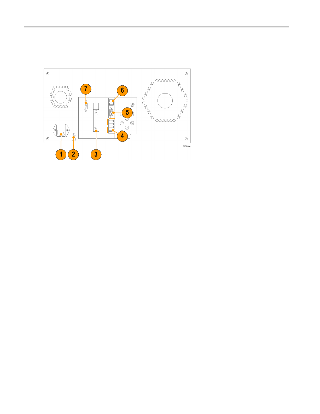
Figure 4: Rear panel connectors
Table 8:
Connector Description
1
2
3 IEEE4888
4
5
6 LAN
7
Rear panel power and communications connectors
AC power Connect a suitable power cord to match the local power outlet type.
Chassis
ground screw
USB Four USB connectors (two additional connectors are located on the front of the instrument).
EO
VID
DPP SI LINK Miniature type D connector for standard RS232 communication.
Connect a common ground to other instruments.
GPIB connector.
ect USB devices such as keyboard, mouse, or USB flash drive.
Conn
itor/display connector. Connect an external display device. Earlier models have VGA
Mon
connectors, newer versions have DVI connectors (DVI adapters are available).
Connect the instrument to a network for remote control operation, file sharing, and other
network operations.
8 Tektronix BERTScope Bit Error Rate Analyzers Quick Start User Manual
The following figure and table describe the rear panel BNC connectors. Pattern Generator connectors are on a blue
background; Er
ror Detector connectors are on a green background.
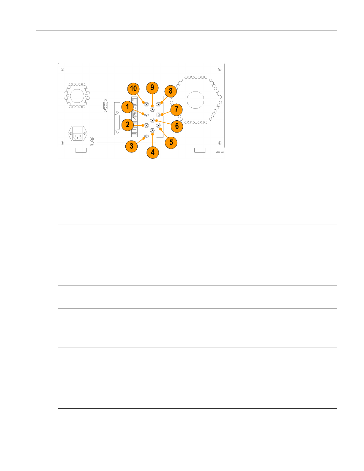
Figure 5: Rear panel BNC connectors
Table 9: Rear panel BNC connectors
Operation
Connector Description
1
PAT START Pattern Start input. Use this input connector to simultaneously synchronize the patterns of
multiple data streams from multiple instruments.
2
PAGE SEL Page Select. If a User Pattern file with two pages is loaded into the Generator, this signal
selects which page is being transmitted, based on the TTL level of the input signal. A logic 0
(low) selects Page A; a logic 1 (high) selects Page B.
3
DET START Detector Start Input. Use this input to synchronize the Error Detector with external
equipment. (LVTTL logic level, >1 kΩ into 0 V)
4
SI OUT Sine Interference Out. Use this connector to output a voltage waveform when the Sine
Interference mode is set to External. The voltage range is from 0 mv to 3.0 V. For e xample,
use this signal with external equipment to apply sinusoidal interference to an optical signal.
5
REF- OUT Reference Output (–). Use this connector with the (+) connector to provide a differential
reference frequency for other instruments (typically 100 MHz). For single-ended
applications, use the (+) connector.
6
LF SIN-OUT Low-Frequency Sine Jitter Out. Use this connector to track the internal sine jitter modulation
frequency. It can be used to ensure that two BERTScope analyzers are both in-phase or
out-of-phase.
7
REF+ OUT Reference Output (+). Use this connector with the (–) connector to provide a differential
reference frequency for other instruments (typically 100 MHz).
8REFIN
Reference Input. Use this connector to provide an input reference signal (amplitude:
–6 dBm to +6 dBm; frequencies: 10, 100, 106.25, 133.33, 165.25, 166.67, and 200 MHz).
9LFJIT-IN
Low Frequency Jitter In. Use this connector to add external low frequency jitter (DC
to 80 MHz) to the instrument. The maximum signal level for this connector for normal
operation is +10 dBm (2 V
10 HF JIT-IN
BSA286C only. High-frequency jitter insertion input connector. Use this connector to add
external high-frequency jitter (DC to 1 GHz) to the instrument with up to 0.5% UI. Apply
signals up to 16 dBm (4 V
).
p-p
) if needed.
p-p
Tektronix BERTScope Bit Error Rate Analyzers Quick Start User Manual 9

Operation
Menu overview
The BERTScope analyzer is controlled by a graphical user interface and on-screen controls. The on-screen controls can be
accessed with the touch screen or with a mouse and keyboard.
The Home view displays when you first turn on the instrument. The Home view introduces the instrument and provides
high-level on-screen information to help you get started using the instrument. It also provides useful links to help you set up
the instrument, such as connecting to the Internet, connecting to a printer, or accessing the Tektronix BERTScope Web site.
Figure 6: Home view
The Control console is common to all views. It consists of three major areas to help you control and navigate the different
views:
Title bar. The Title bar contains the name of your instrument and a history of recent views or views within a group.
Touch any of the listed views to quickly return to that view.
Control buttons. Use the buttons on the right side of the display to control the overall instrument operation. The following
table provides a high-level overview of each button.
Table 10: Control console button overview
Item Description
Touch View to access a variety of views available on the BERTScope analyzer.
The contents of the pop-up list depend on the features and options available with
your instrument.
Touch Back or Forward to quickly scroll through the history of displayed views. The
buttons become active after selecting different views.
Touch Run to start the Pattern Generator, Error Detector, or other data analysis
application in the current view. The button lights up while the applications are
running. Touch the button a second time to stop the applications.
10 Tektronix BERTScope B it Error Rate Analyzers Quick Start User Manual

Table 10: Control console button overview (cont.)
Item Description
Touch the Print button to print the current view to a designated printer or to a file.
Printer settings are made in the System view, on the Tools tab, under the Setup
column. (Touch View and select System to access the System view).
Touch the Config button to access configuration files, which store the setups of
your instrument.
Touch the Help button for easy access to the online help on the current view.
Touch the Shutdown button to quit the BERTScope application or to turn off the
instrument.
Status bar. The Status bar provides information about the current operating status. It is made up of the following
different areas:
Pattern Generator (Gen) and Error Detector (Det). These areas display the data pattern, measured clock frequency,
and sync
hronization status. The areas will be yellow and display error messages if the system is not in sync.
Operation
Measure
small image to the right animates when an analysis is running.
Local/remote control. This area indicates how the instrument is being controlled, locally or by remote control.
NOTE. The Gen or Det areas are shortcuts; touch one of these areas to take you directly to that view.
d BER, Error Count, Bit Count. Touch this area to display the measured BER, error count, or bit count. The
Tektronix BERTScope Bit Error Rate Analyzers Quick Start User Manual 11

Operation
Access system information
The System view includes access to setup, test, and registry settings and information. You might need access to this
information when you first set up your instrument.
Touch View and then select System.
The System view opens showing separate
tabbed pages to access system information.
Under the
buttons to access setup information, view the
desktop, use the Microsoft tools, or access
the Inte
Touch other tabs in the System view for additional information:
Tools tab, touch any of the
rnet.
The Registry tab displays the current paths in the Windows file system for assets, such as user patterns or configurations.
The Settings tab displays a list of user-definable settings. It also allows you to set preferences, such as whether dialog
boxes appear to recommend calibration as appropriate. It also display product options installed in the instrument.
The About tab provides information about your instrument, such as product name, serial number, and software versions.
The Log tab allows you to view or clear the Error Log file. It also displays the path to the log file on your instrument.
The Self-Test tab allows you to run the self test routine. The results of the self test are displayed on the screen and
saved to the Error Log file.
12 Tektronix BERTScope B it Error Rate Analyzers Quick Start User Manual

Applications
The following examples provide simple exercises to help you get familiar with the BERTScope analyzer and to navigate
the instrument views.
Example 1: Configure the Pattern Generator
Example 1: Config
ure the Pattern Generator
This example
using differential CMI voltage levels.
provides examples of how to set up the Pattern Generator to output PRBS-7 data at a specified data rate
Connect the front panel cables
When connecting cables to the front panel use high quality coaxial cables with APC3.5 or SMA connectors.
Connect three SMA cables on the front panel as described below:
1. Connect an SMA cable from the Pattern Generator + Clock Output connector to the Error Detector Clock Input connector.
Terminate the Pattern Generator – Clock Output with a 50 Ω terminator.
2. Connect two SMA cables from the Pattern Generator +/– Data Output connectors to the Error Detector +/– Data Input
connectors.
3. Power on the instrument.
Set up the Pattern Generator
te the following steps to configure the Pattern Generator.
Comple
1. Touch V
iew on the control console and
then select Generator to display the
Generator view.
Tektronix BERTScope Bit Error Rate Analyzers Quick Start User Manual 13

Example 1: Config
2. Touch the SYNTHESIZER input icon on
the Generator view to open the Internal
Clock Input se
Use Keypad.
3. Enter 1.0 GHz and then touch OK.
The dialog box closes and the
SYNTHESIZER input icon displays the
new clock frequency.
ure the Pattern Generator
ttings box and then select
4. Touch t
5. Select Pattern from the first level list and
he GENERATOR icon button in
the center of the Generator view to open
the Generator settings box.
elect PRBS-7 from the list.
then s
14 Tektronix BERTScope B it Error Rate Analyzers Quick Start User Manual

6. Touch the CLOCK + icon button and
verify that Link Clock +/- Signals is
selected.
This setting links the Clock + and Clock –
outputs together.
7. Select Logic Family in the list and then
select CML f
rom the pop-up list.
Example 1: Config
ure the Pattern Generator
8. Repeat the
outputs for the Data + output icons.
9. Touch the Outputs On/Off button at the
top of the Generator view to enable the
Clock an
When the Generator outputs are turned
on, the clock and data information
displa
buttons.
previous two steps to set the
d Data outputs.
ys under the Clock and Data
attern Generator is now transmitting PRBS-7 data at 1 Gb/s on the clock and differential D ata outputs set to the
The P
industry standard CML levels.
Tektronix BERTScope Bit Error Rate Analyzers Quick Start User Manual 15

Example 2: Set up
the Error Detector
Example 2: Set
This example uses the same setups as Example 1. It provides information on how to set up the Error Detector to accept
differential CML signals and to make a bit error rate measurement.
NOTE. Before continuing, make sure that you have the high-quality coaxial cables as describe in Example 1. (See page 13,
Connect the front panel cables.)
1. Touch View on the control console and
then select Detector to display the
Detector view.
up the E rror Detector
2. Touch the Data button, select Interface
Mode, and then select Differential.
3. Touch the Data button again, select
Logic Family, and then select
DIFF-CML/SCFL.
16 Tektronix BERTScope B it Error Rate Analyzers Quick Start User Manual
Example 2: Set up
the Error Detector
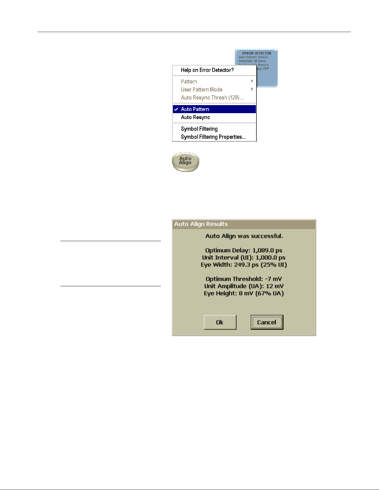
4. Touch t he Error
Auto Pattern from the list.
This enables the Error Detector to compare
all known PRBS
acquiring synchronization.
5. Clear the Auto Resync selection if it is
selected.
6. Touch the A uto Align button at the top
of the Detector view.
The Auto Al
measurement point with the incoming
data signal. This moves the delay timing
and volta
sampling point in the received eye for
making BER measurements.
The Auto Align Results dialog box displays
if the Auto Align process is successful and
nization is achieved.
synchro
Detector icon and select
data patterns when
ign optimizes the data
ge threshold to find the best
NOTE. You might be asked to recalibrate
the delay element when you touch the
ign button. The instrument monitors
Auto Al
changes in data frequency and temperature;
it can automatically recalibrate the built-in
le delay element within a few seconds.
variab
7. Click Ok to close the dialog box.
Tektronix BERTScope Bit Error Rate Analyzers Quick Start User Manual 17

Example 2: Set up
8. Verify that the data pattern type and
the data rate are the same for the
Pattern Gener
(as displayed on the Status Bar at the
bottom of the screen).
the Error Detector
ator and Error Detector
NOTE. In addi
between the views by touching or clicking the Pattern Generator or Error Detector areas of the Status Bar at the bottom
of the screen.
Identify P
If the Pattern Generator and the Error Detector are not synchronized, you must address the problem before continuing. Use
the following steps to help identify the source of the synchronization problems:
1. Verify that you are using the correct, high-quality coaxial cables with APC3.5 or SMA connectors.
2. Carefully check the cable connections to the instrument and the polarity of the connections; make any corrections
as needed.
3. Check that the Pattern Generator has its clock outputs switched on (touch Outputs On/Off).
4. If the status information on the bottom of the Error Detector says Unstable Clock, check for the following:
5. Verify that the Status Bar at the bottom of the Generator and Detector views s how the same data type and data rate.
If synchronization is not achieved, the Statu s Bar will be a bright yellow c olor and displays No Sync. If this happens,
check for the following:
tion to using the View menus to navigate between the Generator and Detector views, you can easily navigate
attern Generator and Error Detector synchronization problems.
Check that the Pattern Generator clock has the internal clock source selected, rather than external.
Check that the Clock Input termination is set to the same termination as the Generator clock output.
Check that the Error Detector Data Input termination is set to the same termination as the Generator output setting.
Check that the Error Detector Data Input is set to Differential input.
6. Verify that the data type is PRBS-7. If not, check for the following:
Check that the Data Type setting on the Generator view is set to PRBS-7. If necessary reset it to PRBS-7.
Check that the Data Type setting on the Detector view is set to PRBS-7. If necessary reset it to PRBS-7.
7. Verify that the X1/X2 settings in the Detector view are correct for your application.
8. Verify that the Generator Clock rate is set to 1 GHz. If necessary, reset it to 1.0 GHz.
9. Verify that the Error Detector settings are the same as the Generator Clock and Data settings. This includes the Interface
Mode and Logic F amily settings. Change them as necessary.
10. Try to resynchronize again by touching the Auto Align button.
18 Tektronix BERTScope B it Error Rate Analyzers Quick Start User Manual

Example 3: Reset
Example 3: Reset the BER and R esyncs to zero
This example assumes that you have completed steps in this Examples 1 and 2 and that the instrument has achieved
synchronization.
1. Touch the Run on the Control console
two times to start and stop the detector.
The button changes color when the
instrument is running.
2. Touch t he Reset Results button at
the top of the screen to reset the
measurement results.
3. Check the Detector view for the following:
The clock rate (1,000.00 Mbit/s)
matches th
transmitted by the Generator.
The data type is set to PBRS-7.
e 1 GHz rate being
the BER and Resyncs to zero
The Detector Results box indicates
zero BER and zero resyncs.
Tektronix BERTScope Bit Error Rate Analyzers Quick Start User Manual 19

Reference
Reference
Operating system restore
The BERTScope analyzer contains an operating system restore file in a separate partition of the hard drive. Use this file
to restore the instrument operating system.
CAUTION. Using the restore process reformats the hard drive and reinstalls the operating system. All saved data is lost. If
possible, save important files to external media before performing a system restore.
1. Restart the instrument. During the boot-up process you will see the following message at the top of the screen:
Acronis Loader
Press F5 to start the Acronis Startup Recovery Manager.
2. Repeatedly press the F5 key until the Acronis True Image Tool opens. There is a 15-second delay after the message
appears until the instrument proceeds with normal instrument startup. If the instrument does not open the Acronis
application, power off the instrument, then power on the instrument and try again.
3. Touch Restore.
4. In the Confirmation dialog box, touch Yes to restore the instrument operating system, or No to exit the restore process.
The restore process takes approximately 30 minutes; the actual time depends on the instrument configuration.
5. If you have not already done so, go to the Tektronix Web site to download the application software
(www.tektronix.com/software) and follow the instructions to install the software for your instrument.
20 Tektronix BERTScope B it Error Rate Analyzers Quick Start User Manual

User service
This section describes high-level service information and procedures for your instrument.
Service offerings
Tektronix provides service to cover repair under warranty and other services that are designed to meet your specificservice
needs.
her providing warranty repair service or any of the other services listed below, Tektronix service technicians are well
Whet
equipped to service the logic analyzers. Services are provided at Tektronix Service Centers and on-site at your facility,
depending on your location.
ranty repair service
War
Tektronix warrants this product as described in the warranty statements at the front of this manual. Tektronix technicians
provide warranty service at most Tektronix service locations worldwide. The Tektronix product catalog lists all service
locations worldwide.
User service
Calibration and repair service
In addition to warranty repair, Tektronix Service offers calibration and other services that provide cost-effective solutions to
your service needs and quality standards compliance requirements. Tektronix instruments are supported worldwide by the
leading-edge design, manufacturing, and service resources of Tektronix to provide the best possible service.
General care
Protect the instrument from adverse weather conditions. The instrument is not waterproof. Do not store or leave the
instrument where the display will be exposed to direct sunlight for long periods of time.
CAUTION. To avoid damage to the instrument, do not expose it to sprays, liquids, or solvents.
Preventive maintenance
Preventive maintenance mainly consists of periodic cleaning. Periodic cleaning reduces instrument breakdown and
increases reliability. Clean the instrument as needed, based on the operating environment. Dirty conditions may require
more frequent cleaning than computer room conditions.
Clean the flat panel display
The flat panel display is a soft plastic display and must be treated with care during cleaning.
CAUTION. Improper cleaning agents or methods can damage the flat panel display.
Tektronix BERTScope Bit Error Rate Analyzers Quick Start User Manual 21

User service
Do not use abrasive cleaners or commercial glass cleaners to clean the display surface.
Do not spray liquids directly on the display surface.
Do not scrub the display with excessive force.
Avoid getting moisture inside the instrument while cleaning the display; use only enough solution to dampen the wipe.
Clean the flat panel display surface by gently rubbing the display with a cleanroom wipe (such as Wypall Medium Duty
Wipes, #0570
1, available from Kimberly-Clark Corporation).
If the displa
display surface. Avoid using excess force or you may damage the plastic display surface.
y is very dirty, moisten the wipe with distilled water or a 75% isopropyl alcohol solution and gently rub the
Clean the exterior surfaces
Clean the exterior surfaces with a dry, lint-free cloth or a soft-bristle brush. If dirt remains, use a cloth or swab dampened with
a 75% isopropyl alcohol solution. A swab is useful for cleaning in narrow spaces around the controls and connectors. Do not
use abrasive compounds on any part of the instrument.
To avoid damaging the instrument follow these precautions:
Avoid getting moisture inside the instrument during external cleaning and use only enough solution to dampen the
cloth or swab.
Do not wash the front-panel power switch. Cover the switch while washing the instrument.
Use only deionized water when cleaning. Use a 75% isopropyl a lcohol solution as a cleanser and rinse with deionized
water.
Do not use chemical cleaning agents; they may damage the instrument. Avoid chemicals that contain benzene, toluene,
xylene, acetone, or similar solvents.
Battery information
The coin cell battery on the instrument computer motherboard is not a user replaceable part. The coin cell battery is not
rechargeable. Under no circumstances attempt to recharge the battery.
22 Tektronix BERTScope B it Error Rate Analyzers Quick Start User Manual

Connector replacement
The Pattern Generator CLOCK OUTPUT and CLOCK INPUT connectors and the Error Detector DATA O UTPUT and DATA
INPUT connectors use 3.5 mm to PAC Planar Crown® adapters. These facilitate user replacement of the adapter, should it
become damaged. Replacement adapters can be ordered from Tektronix.
Replace the front panel connectors
1. Remove a damaged connector by grasping the knurled outer part of the ring with your fingers and turning
counterclockwise.
Do not allow foreign material to enter the connector body when replacing the adapter.
2. Position the two locating tabs in the corresponding slots of the instrument-mounted part of the connector and seat
the replac
ement adapter.
User service
3. Align the r
Tightene
to tighten it.
etaining ring and tighten by rotating clockwise
d the connector finger-tight. To avoid over-tightening and possibly damaging the connector, do not use a tool
Fuse replacement
The instrument is protected by a fuse placed in series with the power line input. The fuse is conservatively rated and should
never open through the life of the instrument. A blown fuse would generally indicate a problem with the instrument which
requires factory service. It is recommended that you arrange to have the instrument serviced if you experience a blown fuse.
Instrument calibration
The instrument uses digital calibration of the output buffers. To maintain the accuracy of the output amplitude and offset,
annual calibration is recommended. Contact Tektronix to schedule instrument calibration.
Repac
k the instrument for shipment
If the instrument is to be shipped to a Tektronix service center for repair, attach a tag showing the following information:
Name of the product owner
Address of the owner
Instrument serial number
A description of the problems encountered and/or service required
When packing an instrument for shipment, use the original packaging. If it is unavailable or not fit for use, contact your
Tektronix representative to obtain new packaging.
Tektronix BERTScope Bit Error Rate Analyzers Quick Start User Manual 23

Specifications
Specification
Table 11: PC-related specifications
Characteristic Description
Display
Touch sensor Analog resistive
Processor
Hard disk drive
DRAM
Operating system Microsoft s® XP Professional
Remote control
Network connection 100 base T Ethernet LAN
Supported interfaces USB 2.0 (6 total, 2 front, 4 rear)
Table 12: Physical specifications
Characteristic Description
Weight
Dimensions
Height
Width
Depth
s
TFT Touch screen, 640 x 480 VGA
Pentium® P4; 1.5 GHz or greater
160 GB or greater
2GB
IEEE-488 (GPIB) or TCP/IP
DVI/VGA external display
25 kg (55 lbs), instrument only
34.5 kg (76 lbs), shipping
22 cm (8.75 in)
39.4 cm (15.5 in)
52 cm (20.375 in)
Table 13: Environmental specifications
Characteristic Description
Temperature
Operating +10 °C to +35 °C (50 °F to 95 °F), with 15 °C (59 °F)/hour maximum gradient, non
condensing, derated 1 °C (34 °F) per 300 m (984 ft) above 1500 m (4921 ft) altitude
Nonoperating
Humidity
Operating 5% to 95% relative humidity at up to 30 °C (86 °F)
Nonoperating
Altitude
Operating To 3000 m (9843 ft.)
Nonoperating
–20 °C to +60 °C (–4 °F to 140 °F), with 30 °C (86 °F)/hour maximum gradient
5% to 65% relative humidity above 30 °C (86 °F) up to 35 °C (95 °F), non
condensing, limited by maximum w et-bulb temperature of 29 °C (84 °F), derates
relative humidity to 65% at +35 °C (95 °F)
5% to 95% relative humidity at up to 30 °C (86 °F)
5% to 65% relative humidity above 30 °C (86 °F) up to 60 °C (140 °F), non
condensing, limited by maximum w et-bulb temperature of 29 °C (84 °F), derates
relative humidity to 12% at +60 °C (140 °F)
To 12,000 m (39,370 ft.)
24 Tektronix BERTScope B it Error Rate Analyzers Quick Start User Manual

Index
Index
A
About tab, 12
accessories
optional, 1
standard, 1
application software, 20
B
battery information, 22
C
on, 23
calibrati
cleaning
exterior, 22
flat panel
clearance requirements, 2
clock input
Error De
clock output
Pattern Generator, 6
complia
EMC, v
environmental, viii
optica
safety, vi
compliance information, v
connec
connectors
Error Detector, 7
front
Pattern Generator, 6
rear panel, 8, 9
ol buttons, 10
contr
Control console, 10
conventions, x
display, 21
tector, 7
nce
l transmitter, xi
tor replacement, 23
panel, 5, 6, 7
D
a input
dat
Error Detector, 7
data output
tern Generator, 6
Pat
detector start input
Error Detector, 9
cumentation, x
do
DVI connector, 8
E
electrostati
environmental
error blank input
Error Detec
error output
ESD, 2
external clock input
c discharge, 2
considerations, 2
specificatio
Error Detector, 7
clock input, 7
data input, 7
detector s
error blank input, 7
error output, 7
front pane
marker input, 7
set up, 16
synchron
trigger output, 7
Error Det
Pattern
ns, 24
tor
tart input, 9
l connectors, 7
ization problems, 18
ector, 7
Generator, 6
F
features and benefits, i x
flat panel display
ng, 21
cleani
front panel
connectors, 5, 6, 7
panel connectors
front
Error Detector, 7
Pattern Generator, 6
fuse
replacement, 23
specifications, 2
H
h-frequency jitter input
hig
Pattern Generator, 6, 9
Home view, 3, 10
K
y features, ix
ke
key specifications, xii
L
Log tab, 12
low-frequen
low-frequency sine jitter out
cy sine jitter in
Pattern Generator, 9
Pattern Gene
rator, 9
M
maintenance
cleaning, 21, 22
preventiv
manual
conventions, x
marker inp
Error Detector, 7
e, 21
ut
O
on-screen controls, 10
elp, x
online h
operating requirements, 2
operating system restore, 20
al accessories, 1
option
options, xii
P
packaging, 23
elect
page s
Pattern Generator, 9
Pattern Generator
output, 6
clock
data output, 6
external clock input, 6
t panel connectors, 6
fron
high-frequency jitter input, 6, 9
low-frequency sine jitter in, 9
frequency sine jitter out, 9
lowpage select, 9
pattern start input, 9
erence in, 9
ref
reference out, 9
set up, 13
e interference out, 9
sin
subrate clock, 6
subrate clock output, 6
nchronization problems, 18
sy
trigger output, 6
Tektronix BERTScope Bit Error Rate Analyzers Quick Start User Manual 25

Index
pattern start input
Pattern Genera
power off procedure, 4
power on procedure, 3
power require
preventive maintenance, 21
product options, xii
product over
tor, 9
ments, 2
view, xi
R
rear panel
connectors, 8, 9
reference i
reference out
Registry tab, 12
repackaging, 23
repair ser
requirements
n
Pattern Generator, 9
Pattern Ge
clearance, 2
operatin
power, 2
voltage, 2
nerator, 9
vice, 21
g, 2
S
Safety S
self test, 3, 12
service offerings, 21
ummary, iii
Settings tab, 12
shut down proce
sine interference out
Pattern Generator, 9
site consider
specifications
altitude, 24
environment
fuse, 2
humidity, 24
key, xii
PC-related, 24
physical, 24
temperatur
standard accessories, 1
static precautions, 2
Status bar
subrate clock
Pattern Generator, 6
subrate cl
Pattern Generator, 6
supported instruments, xi
synchron
System view, 12
About tab, 12
Log tab,
Registry tab, 12
Self test tab, 12
Setting
Tools tab, 12
dure, 4
ations, 2
al, 24
e, 24
,11
ock output
ization problems, 18
12
s tab, 12
T
Tools tab, 12
touch
defined, x
trigger output
Error Detector, 7
Pattern Gene
troubleshooting
operating system restore, 20
synchroniza
rator, 6
tion problems, 18
V
VGA connector, 8
view
defined, x
voltage
requirements, 2
W
warranty
service, 21
26 Tektronix BERTScope B it Error Rate Analyzers Quick Start User Manual
 Loading...