


Technical Reference
Bench Test Instruments and
Handheld Oscilloscopes
Basic Service
061-4124-02
Warning
The servicing instructions are for use by qualified
personnel only. To avoid personal injury, do not
perform any servicing unless you are qualified to
do so. Refer to all safety summaries prior to
performing service.
www.tektronix.com

Copyright © Tektronix, Inc. All rights reserved. Licensed software products are owned by Tektronix or its subsidiaries or
suppliers, and are protected by national copyright laws and international treaty provisions.
Tektronix products are covered by U.S. and foreign patents, issued and pending. Information in this publi cation supercedes
that in all previously published material. Specifications and price change privileges reserved.
TEKTRONIX and TEK are registered trademarks of Tektronix, Inc.
Contacting Tektronix
Tektronix, Inc.
14200 SW Karl Braun Drive
P.O. Box 500
Beaverton, OR 97077
USA
For product information, sal es, service, and technical support:
H In North America, call 1-800-833-9200.
H Worldwide, visit www.tektronix.com to find contacts in your area.

Service Reference
This manual contains the Performance Verification and Adjustment procedures
for many benchtop products. Table i lists the products supported by this manual.
Table i: Benchtop and handheld products supported by this manual
Products
PS280 and PS283 Power Supplies
PS2520, PS2520G, PS2521, and PS2521G Power Supplies
TAS 210 and TAS 220 Digital Oscilloscopes
TMM420 Digital Multimeter
THM500 Series Multimeter/Scope
Service information of products not provided in this manual may be available
under separate cover. Table ii provides a list of many handheld and benchtop
instruments and their service documentation.
Table ii: Handheld and benchtop instruments service manuals
Product Tektronix part number
212 Oscilloscope 070-5053-00
214 Oscilloscope 070-5055-00
214 Storage Oscilloscope 070-1483-00
221 Oscilloscope 070-1573-01
222 Digital Storage Oscilloscope 070-7459-00
222A DSO:
B010100 thru B039999
B040000 and above
222PS Power Scout 070-8098-02
224 Digital Storage Oscilloscope 070-8405-02
305 DMM Oscilloscope 070-2423-01
314 Storage Oscilloscope 070-1824-00
335 Oscilloscope 070-1943-01
336 Digital Storage Oscilloscope 070-4421-00
2201 Portable Oscilloscope 070-7189-00
2205 Oscilloscope 070-6716-00
070-8330-00
070-8330-02
Bench Test Instruments and Handheld Oscilloscopes Basic Service
i

Service Reference
Table ii: Handheld and benchtop instruments service manuals (cont.)
Product Tektronix part number
2211 Oscilloscope 070-7234-00
2214 Digital Storage Oscilloscope 070-7783-00
2220 Digital Storage Oscilloscope 070-5302-00
2221A Oscilloscope:
B010100 to B019999
B020000 and above
2225 Oscilloscope 070-6299-00
2230 Digital Storage Oscilloscope 070-4999-00
2232 Digital Storage Oscilloscope:
B010100 to B029999
B030000 and above
2235 AN/USM-488 Oscilloscope 070-4977-00
2245 Portable Oscilloscope 070-6276-00
070-8157-01
070-8549-00
070-7067-01
070-8548-00
2245A Portable Oscilloscope:
B010100 to B015999
B016000 and above
2246A Portable Oscilloscope 070-6555-00
2246/1Y/2R/2246 Mod A 070-7062-00
2247A Portable Oscilloscope 070-6367-00
2252 Portable Oscilloscope 070-7838-01
2335 Oscilloscope 070-4116-00
2336 Oscilloscope 070-4118-00
2336YA Oscilloscope 070-5011-00
2337 Oscilloscope 070-4120-00
TAS 455/465 Oscilloscope 070-8524-02
TAS 465 Oscilloscope 070-9403-00
TAS 475/485 Oscilloscope:
B010100 to B020099
B020100 and above
TDS 210/220 Oscilloscope 070-9693-01
TDS 310/320/350 Oscilloscope 070-8570-05
TDS 340/340A/360/380 Oscilloscope 070-9435-02
070-6557-00
070-7672-00
070-8878-01
070-9404-00
THS 710/720/730 Oscilloscope 070-9246-03
ii
Bench Test Instruments and Handheld Oscilloscopes Basic Service

General Safety Summary
Review the following safety precautions to avoid injury and prevent damage to
the products in this manual or any products connected to them. To avoid
potential hazards, use these products only as specified.
Only qualified personnel should perform service procedures.
While using these products, you may need to access other parts of the system.
Read the General Safety Summary in other system manuals for warnings and
cautions related to operating the system.
ToAvoidFireor
Personal Injury
Use Proper Power Cord. To avoid fire hazard, use only the power cord specified
for the product you are using.
Use Proper Voltage Setting. B efore applying power, ensure that the line selector is
in the proper position for the power source being used.
Connect and Disconnect Properly. Do not connect or disconnect probes or test
leads while they are connected to a voltage source.
Ground the Product. Some of these products are grounded through the grounding
conductor or the power cord. To avoid electric shock, the grounding conductor
must be connected to earth ground. Before making connections to the input or
output terminals of the product you are using, ensure that the product is properly
grounded.
Observe All Terminal Ratings. To avoid fire or shock hazard, observe all ratings
and markings on the product you are using. Consult the product manual for
further ratings information before making connections to the product.
Do not apply a potential to any terminal, including the common terminal, that
exceeds the maximum rating of that terminal.
Replace Batteries Properly. Replace batteries only with the proper type and rating
specified.
Recharge Batteries Proper ly. Recharge batteries for the recommended charge
cycle only .
Use Proper AC Adapter. Use only the AC adapter specified for the product you
are using.
Bench Test Instruments and Handheld Oscilloscopes Basic Service
iii

General Safety Summary
Do Not Operate Without Covers. Do not operate these products with covers or
panels removed.
Use Proper Fuse. Use only the fuse type and rating specified for the product you
are using.
Avoid Exposed Circuitry. Do not touch exposed connections and components
when power is present.
Do Not Operate in Wet/Damp Conditions. To avoid electric shock, do not operate
these products in wet or damp conditions.
Do Not Operate in Explosive Conditions. To avoid injury or fire hazard, do not
operate these products in an explosive atmosphere.
Keep Product Surfaces Clean and Dry. To avoid electric shock and erroneous
readings, keep probe surfaces clean and dry.
Symbols and Terms
Provide Proper Ventilation. Refer to the product installation instructions for details
on installing the product so it has proper ventilation.
Terms in this Manual. These terms may appear in this manual.
WARNING. Warning statements identify conditions or practices that could result
in injury or loss of life.
CAUTION. Caution statements identify conditions or practices that could result in
damage to this product or other property.
Terms on the Products. These terms may appear on the product:
DANGER indicates an injury hazard immediately accessible as you read the
marking.
WARNING indicates an injury hazard not immediately accessible as you read the
marking.
CAUTION indicates a hazard to property including the product.
iv
Bench Test Instruments and Handheld Oscilloscopes Basic Service

General Safety Summary
Symbols on the Product. The following symbols may appear on the product:
DANGER
High Voltage
Protective Ground
(Earth) Terminal
ATTENTION
Refer to Manual
Double
Insulated
Bench Test Instruments and Handheld Oscilloscopes Basic Service
v

Service Safety Summary
Only qualified personnel should perform service procedures. Read this Service
Safety Summary and the General Safety Summary before performing any service
procedures.
Do Not Service Alone. Do not perform internal service or adjustments of this
product unless another person capable of rendering first aid and resuscitation is
present.
Disconnect Power. To avoid electric shock, disconnect the main power by means
of the power cord or, if provided, the power switch.
Use Caution When Servicing the CRT. To avoid electric shock or injury, use
extreme caution when handling the CRT. Only qualified personnel familiar with
CRT servicing procedures and precautions should remove or install the CRT.
CRTs retain hazardous voltages for long periods of time after power is turned off.
Before attempting any servicing, discharge the CRT by shorting the anode to
chassis ground. When discharging the CRT, connect the discharge path to ground
and then the anode. Rough handling may cause the CRT to implode. Do not nick
or scratch the glass or subject it to undue pressure when removing or installing it.
When handling the CRT, wear safety goggles and heavy gloves for protection.
Use Care When Servicing With Power On. Dangerous voltages or currents may
exist in this product. Disconnect power, remove battery (if applicable), and
disconnect test leads before removing protective panels, soldering, or replacing
components.
To avoid electric shock, do not touch exposed connections.
X-Radiation. To avoid x-radiation exposure, do not modify or otherwise alter the
high-voltage circuitry or the CRT enclosure. X-ray emissions generated within
this product have been sufficiently shielded.
vi
Bench Test Instruments and Handheld Oscilloscopes Basic Service

Preventing Electrostatic Discharge
CAUTION. Static discharge can damage internal semiconductor components.
Follow the guidelines listed below to avoid product damage.
When performing service that requires internal access to an instrument, adhere to
the following precautions to avoid damaging internal modules or their components:
H Avoid handling modules or components in areas that have floors or work
surfaces capable of generating a static charge.
H Spray carpeted work areas with a solution of equal parts of water and fabric
softener.
H Wear clothing made from materials that do not accumulate static charges.
Avoid Wool (and some artificial fibers) which build up static charges readily;
wear cotton which conducts electricity and resists static accumulation.
H Minimize the handling of static-sensitive devices.
H Transport and store static-sensitive devices in their protected containers or on
a metal rail. Label any package that contains static-sensitive parts.
H Service instruments and modules at grounded, static-free work stations.
H Do not allow devices capable of generating a static charge on a work station
surface.
H Wear a grounding strap while working with static-sensitive devices.
H Handle circuit boards by their edges, if possible.
H Do not slide static-sensitive components over any surface.
H Do not use high-velocity compressed air to clean or dry components or
modules.
Bench Test Instruments and Handheld Oscilloscopes Basic Service
vii

Preventing Electrostatic Discharge
viii
Bench Test Instruments and Handheld Oscilloscopes Basic Service

Preface
This manual contains service information for a wide range of handheld and
benchtop products. Each section covers a product or related series of products
and includes the following information:
H A product description that details instrument functions, capabilities, and
recommended uses
H A front panel illustration
H A set of electrical, mechanical, environmental, and physical specifications
H A performance verification procedure to ensure the instrument meets
specifications
H An adjustment procedure to return the instrument to factory calibration (not
included for all instruments)
The information contained in this manual is current at the date of publication and
is typical or suggested, not guaranteed. Since manual updates occur at approximately six month intervals, information may be incomplete or missing in some
versions.
Some instruments have optional service information available under separate
cover. This manual does not duplicate information from optional service
manuals. Refer to the optional accessories list in your user manual for Tektronix
part numbers of optional service manuals. A list of Handheld and Benchtop
instruments manuals can also be found in Table ii on Page i.
NOTE. This manual provides the necessary service information to verify that
your instrument is working properly. Should you have service-related questions
not covered in either this manual or in an optional service manual, please
contact your Tektronix Service Center for additional information.
For product warranty information, refer to the user manual supplied with your
instrument.
Bench Test Instruments and Handheld Oscilloscopes Basic Service
ix

Preface
x
Bench Test Instruments and Handheld Oscilloscopes Basic Service

Instructions Manual
PS280 and PS283
Power Supplies
070-9894-01
www.tektronix.com


Table of Contents
PS280 and PS283 Specifications 3..............................
PS280 and PS283 Performance Verification 7....................
Test Equipment 8..................................................
Constant Current Load Regulation Check 9.............................
Constant Current Ripple and Noise Check 11............................
Constant Voltage Regulation Check 13..................................
PS280 and PS283 Adjustment Procedures 15.....................
List of Adjustments 15..............................................
Test Equipment 16..................................................
Preparation for Adjustment 16........................................
Independent Mode Adjustments 19.....................................
Series Tracking Mode Adjustments 21..................................
Parallel Tracking Mode Adjustments 22.................................
5 V Fixed Output Adjustments 23......................................
Bench Test Instruments and Handheld Oscilloscopes Basic Service
i

Table of Contents
ii
Bench Test Instruments and Handheld Oscilloscopes Basic Service

PS280 and PS283 Power Supplies
The Tektronix PS280 and PS283 Laboratory DC Power Supplies are multifunction benchtop or portable instruments. These regulated triple output power
supplies provide one fixed 5 V, 3 A output suitable for powering logic circuits
and two variable 0 to 30 V outputs useful in a wide variety of test and experimental uses.
The current output of the PS280 varies from 0 to 2 A. The current output of the
PS283 varies from 0 to 1 A. In all other respects, the instruments are identical.
Unless otherwise noted, descriptions and procedures in this manual apply to both
instruments.
The front panel switches provide three modes of operation for the PS280 and
PS283 power supplies:
H Independent mode: the output voltage and current of each supply is
controlled independently.
H Series mode: the variable outputs are connected in series and the controls of
the MASTER power supply adjust the voltages or currents of both supplies.
Series mode allows the supplies to vary from 0 to 60 V at 0 to 2 A for the
PS280 and 0 to 60 V at 0 to 1 A for the PS283.
H Parallel mode: the variable outputs are connected in parallel and the controls
of the MASTER power supply adjust the voltages or currents of both
supplies. Parallel mode allows the supplies to vary from 0 to 4 A at 0 to
30 V for the PS280 and 0 to 2 A at 0 to 30 V for the P S283.
Figure 1: PS280 DC Power Supply
Bench Test Instruments and Handheld Oscilloscopes Basic Service
1

PS280 and PS 283 Power Supplies
2
Bench Test Instruments and Handheld Oscilloscopes Basic Service

PS280 and PS283 Specifications
The characteristics listed in this section apply under the following conditions:
H The instrument operates in a 0_ to 40_ C(32_ to 104_ F) ambient environ-
ment, unless otherwise noted.
H The instrument warms up for at least twenty minutes.
NOTE. All characteristics are warranted unless marked “typical”. Typical
characteristics are not guaranteed but are provided for the convenience of the
user.
Table 1: Operational characteristics
Characteristic Description
Outputs Onefixed5VDC,twovariable0to30VDC
Voltage (5 V Fixed Supply) 5.0 VDC ±0.25 VDC at 3.0 A maximum, foldback current limited
Voltage (0 to 30 V Supplies) PS280: 0 to 30 VDC constant at 2.0 A constant, maximum
PS283: 0 to 30 VDC constant at 1.0 A constant, maximum
Line regulation
5V <5mV
CV PS280: ≤0.01% + 3 mV
PS283: ≤0.01% + 5 mV
CC ≤0.2% + 3 mA
Load regulation
5V ≤0.2%
CV ≤0.01% + 3 mV (rating current ≤3A)
≤0.01% + 5 mV (rating current >3 A PS280)
≤300 mV (0 to 60 VDC single series tracking supply)
CC ≤0.2% + 3 mA
Bench Test Instruments and Handheld Oscilloscopes Basic Service
3

PS280 and PS283 Specifications
Table 1: Operational characteristics (cont.)
Characteristic Description
Ripple and Noise
5V ≤2mV
CV 5Hzto1MHz:≤1mV
CC ≤3mA
RMS
RMS
RMS
Temperature coefficient (CV) ≤300 ppm/ _C
Recovery time (CV) ≤100 s (time to recover after a 50% load change with 0.5 A
minimum)
Tracking error (SLAVE) ≤0.5% + 10 mV of the MASTER supply
Indicator Two 3½ digit, 0.5 inch LED panel displays
Meter indicators 0to30VDC±(0.5% of RDG + 2 digits)
0to2A±(0.5% of RDG + 2 digits)
Insulation
Chassis to terminals ≥20 MΩ at 500 VDC
Chassis to AC cord ≥30 MΩ at 500 VDC
Table 2: Electrical characteristics
Characteristic Description
Line Voltage 90 to 110, 108 to 132, 198 to 242, and 216 to 250 VAC
Line Frequency 50 to 60 Hz
Power Consumption PS280: 348 VA, 250 W maximum
PS282: 254 VA, 172 W maximum
Table 3: Environmental characteristics
Characteristic Description
Operating Temperature 0° to 40° C(32° to 104° F), ≤70% relative humidity
Nonoperating Temperature -- 1 0 ° to +70° C(14° to 158° F), ≤80% relative humidity
4
Bench Test Instruments and Handheld Oscilloscopes Basic Service

Table 4: Physical characteristics
Characteristic Description
Width 255 mm (10.04 inch)
Height 145 mm (5.71 inch)
Depth 335 mm (13.19 inch)
Weight PS280: 11.5 kg (25.3 lb)
PS283: 9.0 kg (19.8 lb)
PS280 and PS283 Specifications
Bench Test Instruments and Handheld Oscilloscopes Basic Service
5

PS280 and PS283 Specifications
6
Bench Test Instruments and Handheld Oscilloscopes Basic Service

PS280 and PS283 Performance Verification
This section contains procedures to verify that PS280 or PS283 power supplies
perform as warranted. Implement the performance verification procedures
whenever the accuracy or function of your instrument is in question.
The performance verification procedures provide a valid confirmation of
instrument electrical characteristics and function under the following conditions:
H The instrument operates in a 20_ to 30_ C(68_ to 104_ F) ambient
environment.
H The instrument warms up for at least 20 minutes before the verification
begins.
H The cabinet remains installed on the instrument.
The PS280 and PS283 performance verification consists of the checks listed in
Table 5.
Table 5: Performance verification checks
Constant Current Load Regulation Check
MASTER Current Regulation (INDEP mode)
SLAVE Current Regulation (INDEP m ode)
MASTER Current Regulation (PARALLEL mode)
Constant Current Ripple and Noise Check
MASTER Current Ripple
SLAVE Current Ripple
Constant Voltage Regulation Check
MASTER Voltage Regulation
SLAVE Voltage Regulation
5 V Fixed Voltage Regulation
The performance verification procedure should be performed annually or after
every 2000 hours of operation if used infrequently.
Bench Test Instruments and Handheld Oscilloscopes Basic Service
7

PS280 and PS283 Performance Verification
Test Equipment
The performance verification procedures use external traceable test equipment to
directly check warranted characteristics.
Alternative test equipment must meet or exceed the intended minimum
requirements. If you substitute equipment, you may need to modify the
performance verification procedures.
NOTE. Before beginning the performance verification procedures, warm up the
test equipment according to the manufacturer’s recommendations.
Table 6: Performance verification and adjustment test equipment
Description Minimum requirements Example product
Oscilloscope 50 MHz, 3% vertical deflection accuracy Tektronix TDS300 Series Oscilloscope
Digital Multimeter 35 V, 4 A, ±0.1% Accuracy Tektronix DMM914 Digital Multimeter
Fixed Resistive Loads 20 Ω 30 W
10 Ω 30 W
2 Ω 5W
1 Ω 30 W
7 Ω 140 W
0.5 Ω 5W
15 Ω 70 W
30 Ω 140 W
7.5 Ω 140 W
30 Ω 40 W
60 Ω 70 W
Variable Resistive Load 0to2Ω 30 W
Shorting Strap with Alligator Clips Insulated
8
Bench Test Instruments and Handheld Oscilloscopes Basic Service

Constant Current Load Regulation Check
To check the constant current load regulation of your power supply, perform the
following tests.
PS280 and PS283 Performance Verification
MASTER Current
Regulation (INDEP mode)
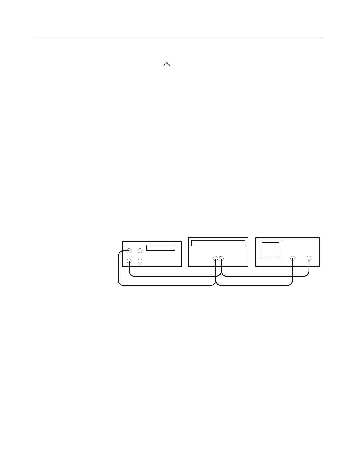
RL2
DMM
Shorting strap
RL1
Power supply
-- +
Figure 2: Constant current test setup
The following check verifies the INDEP mode MASTER current regulation
performance.
1. Set the power supply to the INDEP operating mode by disengaging both
TRACKING mode switches (both switches out).
2. Set the power supply MASTER AMPS/VOLTS selection switch to AMPS.
3. Set up the digital multimeter to measure 25 VDC.
4. Connect the digital multimeter to the + and -- terminals of the power supply
MASTER output.
5. Adjust the power supply MASTER VOLTAGE control until the multimeter
reads 25 VDC.
6. Disconnect the digital multimeter from the power supply.
7. Set the digital multimeter to measure a DC current of at least 1 A (PS280) or
0.5 A (PS283).
8. Connect the digital multimeter and load resistors to the + and -- terminals of
the power supply MASTER output as shown in Figure 2. See Table 7 for the
appropriate load resistor values.
9. Verify that the power supply output current varies less than 0.2%
while shunting load resistor RL1 with the shorting strap. See Figure 2 above.
Bench Test Instruments and Handheld Oscilloscopes Basic Service
±3mA
9

PS280 and PS283 Performance Verification
Table 7: Load resistor values for current checks
PS280 PS283
SLAVE Current Regulation
(INDEP Mode)
Mode
INDEP 20 Ω,30W 2 Ω,5W 20 Ω,30W 2 Ω,5W
PARALLEL 10 Ω,30W 1 Ω,30W 10 Ω,30W 1 Ω,30W
RL1
RL2 RL1 RL2
The following check verifies the INDEP mode SLAVE current regulation
performance.
1. Set the power supply SLAVE AMPS/VOLTS meter selection switch to
AMPS.
2. Set up the digital multimeter to measure 25 VDC.
3. Connect the digital multimeter to the + and -- terminals of the power supply
SLAVE output.
4. Adjust the power supply SLAVE VOLTAGE control until the multimeter
reads 25 VDC.
5. Disconnect the digital multimeter from the power supply.
6. Set the digital multimeter to measure a DC current of at least 1 A (PS280) or
0.5 A (PS283).
MASTER Current
Regulation
(PARALLEL Mode)
7. Connect the digital multimeter and load resistors to the + and -- terminals of
the power supply SLAVE output as shown in Figure 2. See Table 7 for the
appropriate load resistor values.
8. Verify that the power supply output current varies less than 0.2%
±3mA
while shunting load resistor RL1 with the shorting strap. See Figure 2 above.
The following check verifies the PARALLEL mode MASTER current regulation
performance.
1. Set the power supply to the PARALLEL operating mode by engaging both
TRACKING mode switches (both switches in).
2. Set up the digital multimeter to measure 25 VDC.
3. Connect the digital multimeter to the + and -- terminals of the power supply
MASTER output.
4. Adjust the power supply MASTER VOLTAGE control until the digital
multimeter reads 25 VDC .
5. Disconnect the digital multimeter from the power supply.
10
Bench Test Instruments and Handheld Oscilloscopes Basic Service

6. Set the digital multimeter to measure a DC current of at least 1 A (PS280) or
0.5 A (PS283).
7. Connect the digital multimeter and load resistors to the + and -- terminals of
the power supply MASTER output as shown in Figure 2. See Table 7 for the
appropriate load resistor values.
8. Verify that the power supply output current varies less than 0.2% ±5mA
while shunting load resistor RL1 with the shorting strap. See Figure 2 above.
Constant Current Ripple and Noise Check
To check the constant current ripple and noise performance of your power
supply, perform the following tests.
PS280 and PS283 Performance Verification
MASTER Current Ripple
Power supply
-- +
R
S
R
L
Test oscilloscope
Figure 3: Constant current ripple and noise test setup
The following check verifies the MASTER current ripple.
1. Set the power supply to the INDEP operating mode by disengaging both
TRACKING switches (both switches out).
2. Set the power supply MASTER AMPS/VOLTS meter selection switch to
VOLTS.
3. Set the power supply to 25 VDC using the digital display.
4. Connect the test oscilloscope and load resistors to the + and -- terminals of
the MASTER output as shown in Figure 3. See Table 8 for the appropriate
load resistor values.
5. Verify that the peak-to-peak ripple viewed on the oscilloscope is less than
3mV.
Bench Test Instruments and Handheld Oscilloscopes Basic Service
11

PS280 and PS283 Performance Verification
6. Set the power supply to the PARALLEL operating mode by engaging both
TRACKING mode switches (both switches in).
7. Verify that the peak-to-peak ripple viewed on the oscilloscope is less than
2.5 mV.
8. Set the power supply to the SERIES operating mode by disengaging the
right TRACKING mode switch (switch out).
9. Verify that the peak-to-peak ripple viewed on the oscilloscope is less than
5mV.
Table 8: Load resistor values for ripple checks
PS280 PS283
SLAVE Current Ripple
Mode
INDEP 15 Ω,70W 0.5 Ω,5W 30 Ω,40W 0.5 Ω,5W
PARALLEL 7 Ω, 140 W 10 Ω,30W 15 Ω,70W 0.5 Ω,5W
R
L
R
S
R
L
R
S
The following check verifies the SLAVE current ripple.
1. Set the power supply to INDEP operating mode by disengaging both
TRACKING switches (both switches out).
2. Set the power supply SLAVE AMPS/VOLTS meter switch to VOLTS.
3. Set the power supply to 25 VDC using the digital display.
4. Connect the test oscilloscope and load resistors to the + and -- terminals of
the SLAVE output as shown in Figure 3. See Table 8 for the appropriate load
resistor values.
5. Verify that the peak-to-peak ripple viewed on the oscilloscope is less than
3mV.
12
Bench Test Instruments and Handheld Oscilloscopes Basic Service

Constant Voltage Regulation Check
To check the constant voltage regulation of your power supply, perform the
following tests.
Power supply DMM
Figure 4: Constant voltage test setup
-- +
PS280 and PS283 Performance Verification
R
L
MASTER Voltage
Regulation
The following check verifies the MASTER voltage regulation performance.
1. Set the power supply to the INDEP operating mode by disengaging both
TRACKING mode switches (both switches out).
2. Set up the digital multimeter to measure 60 VDC.
3. Connect the digital multimeter and load resistors to the + and -- terminals of
the power supply MASTER output as shown in Figure 4. See Table 9 for the
appropriate load resistor values.
4. Verify that you can adjust the power supply from 0 to 30 V.
5. Set the power supply to the SERIES operating mode by engaging the left
TRACKING mode switch (switch in) and disengaging the right TRACKING
mode switch (switch out).
6. Verify that you can adjust the power supply from 0 to 60 V.
7. Set the power supply to the PARALLEL operating mode by engaging both
TRACKING mode switches (both switches in).
8. Verify that you can adjust the power supply from 0 to 30 V.
Bench Test Instruments and Handheld Oscilloscopes Basic Service
13

PS280 and PS283 Performance Verification
Table 9: Load resistor values for voltage checks
PS280 PS283
SLAVE Voltage Regulation
5 V Fixed Voltage
Regulation
Mode
INDEP 15 Ω,70W 30 Ω,40W
SERIES 30 Ω, 140 W 60 Ω,70W
PARALLEL 7.5 Ω, 140 W 15 Ω,70W
5V FIXED 1.7 Ω,20W 1.7 Ω,20W
R
L
R
L
The following check verifies the SLAVE voltage regulation performance.
1. Set the power supply to the INDEP operating mode by disengaging both
TRACKING mode switches (both switches out).
2. Set up the digital multimeter to measure 30 VDC.
3. Connect the digital multimeter and load resistors to the + and -- terminals of
the SLAVE output as shown in Figure 4. See Table 9 for the appropriate load
resistor values.
4. Verify that you can adjust the power supply from 0 to 30 V.
The following check verifies the 5 V fixed voltage regulation performance.
1. Set up the digital multimeter to measure 5 VDC.
14
2. Connect the digital multimeter and load resistors to the 5V FIXED 3A
terminals. Use the test setup illustrated in Figure 4. See Table 9 for the
appropriate load resistor values.
3. Verify that the power supply maintains an output of 5 V,
±0.25 V.
Bench Test Instruments and Handheld Oscilloscopes Basic Service

PS280 and PS283 Adjustment Procedures
This section contains procedures to adjust PS280 and PS283 power supplies. If
your instrument fails a performance requirement, use these procedures to return
it to factory specifications.
In this section you will find the following information:
H A list of adjustments
H A list of test equipment needed to make the adjustments
H Instructions on how to prepare instruments for adjustment
H Step-by-step adjustment procedures
The procedures in this section do not verify performance. To confirm that your
power supply meets factory specifications, implement the procedures in the
Performance Verification section.
List of Adjustments
Use the adjustments listed in Table 10 to return PS280 and PS283 power
supplies to factory calibration.
Table 10: PS280 and PS283 adjustments
Independent Mode Adjustments
MASTER Voltage Output
SLAVE Voltage Output
MASTER Current Output
SERIES Tracking Mode Adjustments
Series Tracking
PARALLEL Tracking Mode Adjustments
Parallel Tracking
5 V Fixed Output Adjustments
5 V Output
Current Limit
Overload Indicator
Bench Test Instruments and Handheld Oscilloscopes Basic Service
15

PS280 and PS 283 Adjustment Procedures
Test Equipment
To ensure accurate adjustments, use the recommended or equivalent test
equipment specified in Table 6 on page 8. If you substitute equipment, always
choose instruments that meet or exceed the minimum requirements.
NOTE. Before making any adjustment, warm up the test equipment according to
the manufacturer’s recommendations.
Preparation for Adjustment
The following guidelines apply to all PS280 and PS283 power supply adjustments:
Remove Instrument Cover
H Perform the adjustments in a 20_ to 30_ C(68_ to 104
environment with a relative humidity of 75% or less.
H Before making any adjustment, warm up the instrument for at least 20
minutes.
H Read the Safety Summary at the beginning of this manual.
H Do not alter any setting without reading the entire adjustment procedure first.
H Do not alter any setting unless a performance characteristic cannot be met at
the current setting.
You must remove the instrument cover to make internal adjustments.
WARNING. To avoid electrical shock, disconnect the power cord from its source
while removing the instrument cover. Following the adjustment procedure,
replace the instrument cover before using the power supply.
To remove the instrument cover, refer to Figure 5 while performing the following
steps.
1. Remove the two handle mounting screws and remove the handle.
_ F) ambient
16
2. Remove the three screws on the left side and the three screws on the right
side of the instrument.
3. Slide the cover toward the rear of the instrument and lift.
To reinstall the cover, perform steps 1 through 3 above in reverse order.
Bench Test Instruments and Handheld Oscilloscopes Basic Service

PS280 and PS 283 Adjustment Procedures
Figure 5: PS280/PS283 instrument cover removal
Bench Test Instruments and Handheld Oscilloscopes Basic Service
17

PS280 and PS 283 Adjustment Procedures
Circuit Board Locations
Refer to Figure 6 to locate PS280/PS283 internal circuit boards.
Front Panel controls circuit board
Display Assembly circuit board
Master/Slave circuit board
5 V circuit board
18
Figure 6: PS280/PS283 internal circuit board locations
Bench Test Instruments and Handheld Oscilloscopes Basic Service

Independent Mode Adjustments
Refer to Figures 6, 7, and 8 for the circuit board and adjustment locations used in
this procedure.
PS280 and PS 283 Adjustment Procedures
MASTER Vo ltage Output
To adjust the MASTER voltage output, perform the following steps.
1. Disengage both TRACKING mode switches (both switches out) so that the
power supply is in the INDEPendent operating mode.
2. Set the MASTER AMPS/VOLTS meter selection switch to VOLTS.
3. Set the digital multimeter to measure a DC voltage of
±16 mV.
4. Set the PS280/PS283 MASTER VOLTAGE control to minimum (fully
counterclockwise).
5. Connect the digital multimeter to the + and -- terminals of the MASTER
output.
6. Adjust VR102 (Master/Slave circuit board) for a reading of --15 mV, within
±15 mV on the multimeter.
7. Set the digital multimeter to measure a DC voltage of
±35 V.
8. Set the MASTER VOLTAGE control to maximum (fully clockwise).
9. Adjust VR101 (Master/Slave circuit board) for a reading of 31.5 V on the
multimeter.
10. Adjust VR201 (Display Assembly circuit board) until the PS280/PS283
front panel display reads 31.5 V.
11. Disconnect the digital multimeter from the power supply.
VR502
Figure 7: Master/Slave circuit board adjustments
Bench Test Instruments and Handheld Oscilloscopes Basic Service
VR303
VR102
VR103
VR301
VR306
VR302
VR101
19

PS280 and PS 283 Adjustment Procedures
SLAVE Voltage Output
To adjust the SLAVE voltage output, perform the following steps.
1. Disengage both TRACKING mode switches (both switches out) so that the
power supply is in the INDEPendent operating mode.
2. Set the SLAVE AMPS/VOLTS meter selection switch to VOLTS.
3. Set the digital multimeter to measure a DC voltage of
±16 mV.
4. Set the power supply SLAVE VOLTAGE control to minimum (fully
counterclockwise).
5. Connect the digital multimeter to the + and -- terminals of the SLAVE
output.
6. Adjust VR302 (Master/Slave circuit board) for a reading of --15 mV, within
±15 mV on the multimeter.
7. Set the digital multimeter to measure a DC voltage of
±35 V.
8. Set the SLAVE VOLTAGE control to maximum (fully clockwise).
9. Adjust VR301 (Master/Slave circuit board) for a reading of 31.5 V on the
multimeter.
10. Adjust VR601 (Display Assembly circuit board) until the PS280/PS283
front panel display reads 31.5 V.
MASTER Current Output
11. Disconnect the digital multimeter from the power supply.
J1044
VR601
VR602
VR201
VR202
Figure 8: Display Assembly circuit board adjustments
To adjust the MASTER current output, perform the following steps.
1. Disengage both TRACKING mode switches (both switches out) so the
power supply is in the INDEPendent operating mode.
2. Set the MASTER AMPS/VOLTS meter selection switch to AMPS.
3. Set the digital multimeter to measure a DC current of 2 A.
4. Connect the digital multimeter to the + and -- terminals of the MASTER
output.
5. Set the MASTER CURRENT control to maximum (fully clockwise).
20
Bench Test Instruments and Handheld Oscilloscopes Basic Service

PS280 and PS 283 Adjustment Procedures
6. Adjust VR103 (Master/Slave circuit board) for a reading of 1.05 A (PS283)
or 2.1 A (PS280) on the multimeter.
7. Adjust VR202 (Display Assembly circuit board) until the PS280/PS283
front panel display reads 1.05 A (PS283) or 2.1 A (PS280).
8. Disengage both TRACKING mode switches (both switches out) so that the
power supply is in the INDEPendent operating mode.
9. Set the SLAVE AMPS/VOLTS meter selection switch to AMPS.
10. Set the digital multimeter to measure a DC current of 2 A.
11. Connect the digital multimeter to the + and -- terminals of the SLAVE
output.
12. Set the SLAVE CURRENT control to maximum (fully clockwise).
13. Disconnect the digital multimeter from the power supply.
Series Tracking Mode Adjustments
Refer to Figures 6, 7, and 9 for the circuit board and adjustment locations used in
this procedure.
SERIES Tracking
To adjust the series tracking mode, perform the following steps.
1. Engage the left TRACKING mode switch (switch in) and disengage the right
TRACKING mode switch (switch out) so that the power supply is in the
SERIES operating mode.
2. Set the SLAVE CURRENT control to midrange.
3. Set the MASTER VOLTAGE control to near minimum (counterclockwise).
4. Set the digital multimeter to measure a low DC voltage.
5. Connect the digital multimeter to the + and -- terminals of the MASTER
output and adjust the MASTER VOLTAGE control until the digital
multimeter reads 500 mV.
6. Connect the digital multimeter to the + and -- terminals of the SLAVE
output.
7. Adjust VR306 (Master/Slave circuit board) until the voltage output of the
SLAVE output matches the reading obtained from the MASTER output.
8. Set the MASTER VOLTAGE control to maximum (fully clockwise).
9. Set the digital multimeter to measure a DC voltage of
Bench Test Instruments and Handheld Oscilloscopes Basic Service
±35 V.
21

PS280 and PS 283 Adjustment Procedures
10. Connect the digital multimeter to the + and -- terminals of the MASTER
output and note the reading obtained.
11. Connect the digital multimeter to the + and -- terminals of the SLAVE
output.
12. Adjust VR501 (Front Panel Controls circuit board) until the voltage of the
SLAVE output matches the reading obtained from the MASTER output in
step 10 above.
13. Recheck the value of the MASTER output compared to the value of the
SLAVE output. Readjust VR501 if the outputs do not match.
14. Disconnect the test setup.
J3082
VR501
Figure 9: Front Panel Controls circuit board adjustm ents
Parallel Tracking Mode Adjustments
Refer to Figures 6 and 7 for the circuit board and adjustment locations used in
this procedure.
PARALLEL Tracking
To adjust the PARALLEL tracking Mode, perform the following steps.
1. Disengage both TRACKING mode switches (both switches out) so that the
power supply is in the INDEPendent operating mode.
2. Set the MASTER VOLTAGE and CURRENT controls to minimum (fully
counterclockwise).
3. Set the digital multimeter to measure a DC current of 4 A.
4. Connect the digital multimeter to the + and -- terminals of the MASTER
output.
5. Set the MASTER VOLTAGE control to midrange and adjust the MASTER
CURRENT control until a reading of 1 A (PS283) or 2 A (PS280) is
displayed on the multimeter.
22
Bench Test Instruments and Handheld Oscilloscopes Basic Service

NOTE. Do not readjust the CURRENT control setting through the remainder of
this procedure.
6. Engage both TRACKING switches (both switches in) so that the power
supply is in the PARALLEL operating mode.
7. Set the SLAVE CURRENT control to maximum (fully clockwise) and set
the SLAVE VOLTAGE control to midrange.
8. Adjust VR502 (Master/Slave circuit board) until a reading of 2 A (PS283) or
4 A (PS280) is displayed on the multimeter.
9. Disconnect the test setup.
5 V Fixed Output Adjustments
Refer to Figures 6 and 10 for the circuit board and adjustment locations used in
this procedure.
PS280 and PS 283 Adjustment Procedures
5 V Output
To adjust the 5 V fixed output, perform the following steps.
1. Set the digital multimeter to measure a DC voltage of +5.25 V.
2. Connect the digital multimeter to the terminals of the 5 V FIXED 3A output.
3. Adjust VR401 (5 V circuit board) until the multimeter displays 5.00 V
±0.25 V.
4. Disconnect the multimeter from the power supply.
VR401
VR403
VR402
Figure 10: 5 V circuit board adjustments
Bench Test Instruments and Handheld Oscilloscopes Basic Service
23

PS280 and PS 283 Adjustment Procedures
Current Limit
Overload Indicator
To adjust the current limit, perform the following steps.
1. Set the digital multimeter to measure a DC current of 3.25 A.
2. Adjust VR403 (5 V circuit board) fully counterclockwise.
3. Connect a variable load and the multimeter in series to the terminals of the
5 V FIXED 3A output.
4. Adjust the variable load until the multimeter displays 3.25 A.
5. Disconnect the multimeter from the power supply and reconnect the variable
load (without changing the setting) to the terminals of the 5 V FIXED 3A
output.
6. Set the digital multimeter to measure a DC voltage of +5.25 V.
7. Connect the digital multimeter to the terminals of the 5 V FIXED 3A output.
8. Slowly adjust VR403 (5 V circuit board) clockwise until the multimeter
display shows a voltage drop of 5 to 6 mV.
9. Disconnect the test setup.
To adjust the current limit overload indicator, perform the following steps.
1. Set the digital multimeter to measure a DC current of 3.25 A.
2. Connect a variable load and the multimeter in series to the terminals of the
5 V FIXED 3A output.
3. Adjust the variable load until the multimeter displays 3.10 A.
4. Adjust VR402 (5 V circuit board) until the OVERLOAD 5V3A indicator
starts to light on the power supply.
5. Disconnect the test setup.
24
Bench Test Instruments and Handheld Oscilloscopes Basic Service

Instructions Manual
PS2520 and PS2521 Series
Power Supplies
070-9854-03
www.tektronix.com


Table of Contents
PS2520 and PS2521 Series Power Supplies 1.....................
PS2520 and PS2521 Series Specifications 3......................
PS2520 and PS2521 Series Performance Verification 7............
Test Equipment 8..................................................
Set Up 8.........................................................
PS2520 and PS2520G Checks 9......................................
PS2521 and PS2521G Checks 32......................................
PS2520 and PS2521 Series Adjustment Procedures 55..............
List of Adjustments 55..............................................
Test Equipment 56..................................................
Preparation for Adjustment 56........................................
Adjustment Procedure 58............................................
Bench Test Instruments and Handheld Oscilloscopes Basic Service
i

Table of Contents
ii
Bench Test Instruments and Handheld Oscilloscopes Basic Service
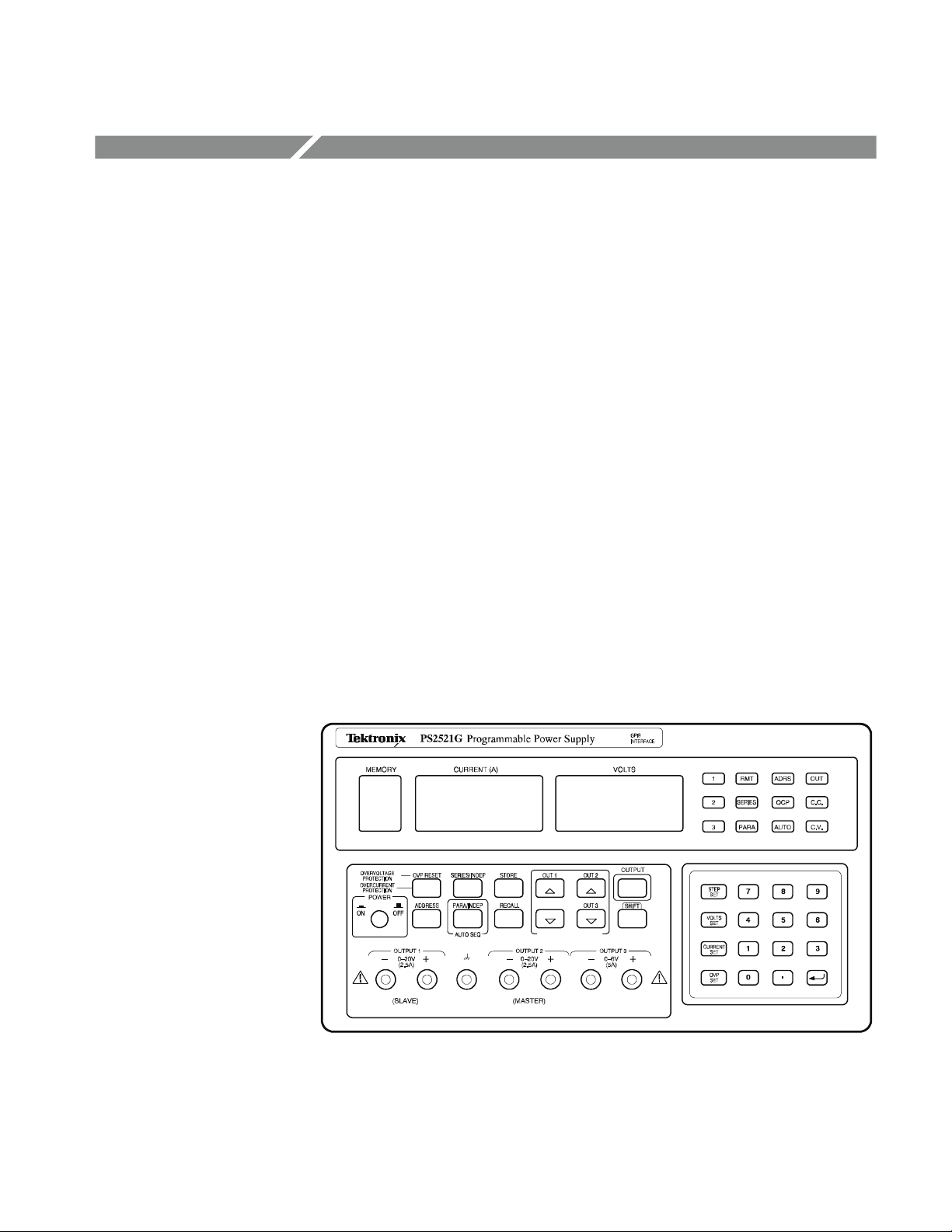
PS2520 and PS2521 Series Power Supplies
The Tektronix PS2520, PS2520G, PS2521, and PS2521G power supplies are
multifunction benchtop or portable instruments. All PS2520 series power
supplies include the following standard features:
H Three high stability low drift outputs (outputs may be configured for
independent, series, or parallel operation)
H Automatic series or parallel tracking
H Push-button controls
H Keypad and up-down key data entry
H Four-digit display of voltage and current
H High resolution digital-to-analog converter
H Memory storage and recall
H Display readout of output, memory, and error codes
H Automatic sequencing with timer
H Self-test diagnostic at power up
H Overvoltage protection (OVP) and overcurrent protection (OCP)
Figure 1: PS2521G power supply
Bench Test Instruments and Handheld Oscilloscopes Basic Service
1

PS2520 and PS 2521 Series Power Supplies
The descriptions and procedures in the following sections apply to all PS2520
series power supplies (unless specifically noted), with the following exceptions:
H The PS2520 and PS2520G power supplies have two variable outputs
providing 0 to 36 V at 0 to 1.5 A and one variable output providing 0 to 6 V
at0to3A.
H The PS2521 and PS2521G power supplies have two variable outputs
providing 0 to 20 V at 0 to 2.5 A and one variable output providing 0 to 6 V
at0to5A.
H The PS2520G and PS2521G include General Purpose Interface Bus (GPIB)
operation.
2
Bench Test Instruments and Handheld Oscilloscopes Basic Service

PS2520 and PS2521 Series Specifications
The characteristics listed in this section apply under the following conditions:
H The power supply operates in a 20_ to 30_ C(68_ to 86_ F) ambient
environment, unless otherwise noted.
H The instrument warms up for at least 20 minutes.
NOTE. All specifications are warranted unless marked “typical.” Typical
characteristics are not guaranteed but are provided for the convenience of the
user.
Table 1: Operational characteristics
Characteristic Description
Independent Output Ratings
PS2520 and PS2520G Twooutputs: 0to36Vat0to1.5A
One output: 0 to 6 V at 3 A
PS2521 and PS2521G Twooutputs: 0to20Vat0to2.5A
Oneoutput: 0to6Vat0to5A
Series Tracking Output Rating
PS2520 and PS2520G 0to72Vat0to1.5A
PS2521 and PS2521G 0to40Vat0to2.5A
Parallel Tracking Output Rating
PS2520 and PS2520G 0to36Vat0to3A
PS2521 and PS2521G 0to20Vat0to5A
Maximum Overvoltage Protection
PS2520 and PS2520G 36 V outputs: 38.5 V
6 V output: 7.0 V
PS2521 and PS2521G 20 V outputs: 22.5 V
6 V output: 7.0 V
Load Effect
Voltage Rear output: ≤3mV
Front output:≤6mV
Current ≤3mA(≤6 mA if rating current > 3.5 A)
Source Effect
Voltage ≤3mV
Current ≤3mA
Bench Test Instruments and Handheld Oscilloscopes Basic Service
3

PS2520 and PS 2521 Series Specifications
Table 1: Operational characteristics (cont.)
Characteristic Description
Resolution
Voltage 10 mV (20 mV if rating voltage > 36 V)
Current 1mA(2mAifratingcurrent>3.5A)
Overvoltage Protection 10 mV (20 mV if rating voltage > 36 V)
Program Accuracy
Voltage ≤0.05% + 25 mV (50 mV if rating voltage > 36 V)
Current ≤0.2% + 10 mA
Overvoltage Protection ≤2% + 0.6 V
RippleandNoise20Hzto20MHz
Voltage Ripple 1mV
Voltage Noise 2mV
Current ≤3mA
Temperature Coefficient 0_ to 40_ C(32_ to 104_ F)
Voltage ≤100 ppm + 3mV
Current ≤150 ppm + 3mA
Readback Resolution
Voltage 10 mV (20 mV if rating voltage > 36 V)
Current 1mA(2mAifratingcurrent>3.5A)
Readback Accuracy
Voltage ≤0.05% + 25 mV (50 mV if rating voltage > 36 V)
Current ≤0.2% + 10 mA
Response Time
10 to 90% (up) ≤100 ms
90 to10% (down) ≤100 ms (≥10% rating load)
Readback Temperature Coefficient
Voltage ≤100 ppm + 10 mV (20 mV if rating voltage > 36 V)
Current ≤150 ppm + 10 mA
1
Drift
Voltage ≤0.03% + 6 mV
Current ≤0.1% + 6 mA
Series Tracking
Tracking Error Voltage ≤0.1% + 50 mV
Load Effect Voltage ≤50 mV
Source Effect Voltage ≤3mV
1
Change in output over an 8 hour interval with a constant line voltage, load, and ambient temperature. Requires a 30
minute warm-up.
RMS
RMS
RMS
(3 mV
(30 mV
(≤5mA
)
p-p
)
p-p
if rating current > 3.5 A)
RMS
4
Bench Test Instruments and Handheld Oscilloscopes Basic Service

PS2520 and PS 2521 Series Specifications
Table 1: Operational characteristics (cont.)
Characteristic Description
Parallel Tracking
Program Accuracy
Voltage ≤0.05% + 25 mV (50 mV if rating voltage > 36 V)
Current ≤0.2% + 20 mA
Overvoltage Protection ≤2% + 0.6 V
Load Effect
Voltage ≤3 mV rear output (≤6 mV front output)
Current ≤6mA(≤12 mA if rating current > 3.5 A)
Source Effect
Voltage ≤3mV
Current ≤6mA
GPIB Capability (Optional IEEE-488.2) SH1, AH1, T6, L4, SR1, RL1, PP0, DC1, DT0, C0, E1
Memory Locations (Store and Recall) 00 to 49 (50 locations)
Timer
Setting Time 1 to 65535 seconds
Resolution 1 second
Table 2: Electrical characteristics
Characteristic Description
Power Source 100, 120, and 220 VAC ±10% at 50 to 60 Hz
240 VAC --10%, +4.2%, at 50 to 60 Hz
Safety ETL list ed to UL 1244
Certified to CSA-C22.2 No 231-M89
Table 3: Environmental characteristics
Characteristic Description
Operating Temperature 0_ to 40_ C(32_ to 104_ F)
Nonoperating Temperature -- 1 0 _ to +70_ C(14_ to 158_ F)
Bench Test Instruments and Handheld Oscilloscopes Basic Service
5

PS2520 and PS 2521 Series Specifications
Table 4: Physical characteristics
Characteristic Description
Width 255 mm (10.04 inch)
Height 145 mm (5.71 inch)
Depth 346 mm (13.62 inch)
Weight 10 kg (22 lbs)
6
Bench Test Instruments and Handheld Oscilloscopes Basic Service

PS2520 and PS2521 Series Performance Verification
This section contains procedures to verify that PS2520, PS2520G, PS2521, or
PS2521G power supplies perform as warranted. Implement the performance
verification procedures whenever the accuracy or function of your power supply
is in question.
The performance verification procedures provide a valid confirmation of
instrument electrical characteristics and function under the following conditions:
H The instrument operates in a 20° to 30° C(68° to 86° F) ambient environ-
ment.
H The instrument warms up for at least 20 minutes.
H The cabinet remains installed on the instrument.
The performance verification procedure should be performed annually or after
every 2000 hours of operation if used infrequently.
The PS2520 series performance verification consists of the checks listed in
Table 5.
Table 5: Performance verification checks
Basic Function
Voltage Set Accuracy
Current Set Accuracy
Overvoltage Protection (OVP) Accuracy
Constant Voltage Load Accuracy
Constant Voltage Source Accuracy
Constant Voltage Ripple and Noi se Accuracy
Constant Current Load and Overcurrent Protection (OCP)
Accuracy
Constant Current Source Accuracy
There are two separate performance verification procedures for the
PS2520/2520G and PS 2521/2521G series instruments. The PS2520/2520G
procedures begin on page 9; the PS2521/2521G procedures begin on page 32.
Use the procedure appropriate to your instrument.
You will find the recommended test equipment and initial settings for all
verification procedures listed on page 8.
Bench Test Instruments and Handheld Oscilloscopes Basic Service
7

PS2520 and PS2521 Series Performance Verification
Test Equipment
The performance verification procedures use external traceable test equipment to
directly check warranted characteristics.
Alternative test equipment must meet or exceed the intended minimum
requirements. If you substitute equipment, you may need to modify the
procedures.
NOTE. Before beginning the performance verification procedures, warm up the
test equipment according to the manufacturer’s recommendations.
Table 6: Performance verification test equipment
Description Minimum requirements Example product
Digital Volt Meter (DVM) 100 V DC, accuracy within ±0.01% Agilent 34401A
Digital Current Meter 5A DC, accuracy within ±0.02% Fluke 45
Oscilloscope 20 MHz, 3% vertical deflection accuracy Tektronix TDS300 Series
Electronic Load 40 V, 8 A CR mode
Vari a c 0to250V,2A
Resistors 2.2 Ω 50 W, 27 Ω 100 W
Set Up
Following a 20 minute warm-up period, preset your power supply to the settings
listed in Table 7.
Table 7: Power supply initial settings
Control Setting
(SHIFT) RECALL Enter 00 on keypad
AUTO SEQ OFF
(SHIFT) OUT 1
OCP OFF
(SHIFT) SERIES/INDEP INDEP
(SHIFT) PARA/INDEP INDEP
OUTPUT OFF
STEP SET (volts) 1
STEP SET (current) 0.1
8
Bench Test Instruments and Handheld Oscilloscopes Basic Service

PS2520 and PS2520G Checks
To verify the function and performance of the PS2520 and PS2520G power
supplies, implement the following checks in sequential order. To verify the
function and performance of the PS2521 and PS2521G power supplies, see
page 32.
NOTE. To clear a memory location, enter “0” as the VOLTS SET and CURRENT
SET values; then save the “0” values to the desired memory location.
For a list of error code descriptions, see your User manual.
PS2520 and PS2521 Series Performance Verification
Basic Function
Complete the following procedures to verify basic instrument function.
Outputs 1, 2, and 3. Use the following steps to verify OUTPUT 1, OUTPUT 2,
and OUTPUT 3 basic function.
1. Press SHIFT
2. Set up the power supply as follows:
VOLTS SET 10 V
CURRENT SET 1 A
OVP SET 38 V
DELAY 3 s
3. Press SHIFT
location. Verify that the MEMORY, CURRENT (A), and VOLTS readouts
display the values listed in step 2 for memory location 01.
4. Reset the power supply as follows:
VOLTS SET 11 V
CURRENT SET 1.1 A
OVP SET 38 V
DELAY 3 s
→ OUT 1; verify that the “1” indicator lights up on the display.
→ STORE → 1 to store the above values in the memory 01
5. Press SHIFT
location. Verify that the MEMORY, CURRENT (A), and VOLTS readouts
display the values listed in step 4 for memory location 02.
6. Press SHIFT
7. Press RECALL LAST; verify that the readouts display the data stored in the
memory 02 location.
Bench Test Instruments and Handheld Oscilloscopes Basic Service
→ STORE → 2 to store the above values in the memory 02
→ RECALL; then enter 1.2 .
9

PS2520 and PS2521 Series Performance Verification
8. Press RECALL LAST again; verify that the readouts now display the data
stored in the memory 01 location.
9. Press RECALL NEXT; verify that the readouts display the data stored in the
memory 02 location.
10. Press OUTPUT ON/OFF. Verify that the “OUT” indicator lights up on the
display.
11. Press AUTO SEQ ON/OFF and verify that the “AUTO” indicator lights up
on the display. Verify that the front panel readouts alternately display the
memory 01 and memory 02 setups from steps 2 and 4 above, every three
seconds.
12. Press AUTO SEQ ON/OFF and OUTPUT ON/OFF. Verify that the “AUTO”
and “OUT” indicators turn off.
13. Press STEP SET. Set the VOLTS SET to 1.00 V.
14. Press VOLTS
and verify that as you attempt to decrease the voltage
below 0.00 V, “Err - 018” appears on the CURRENT (A) and VOLTS
readouts. The voltage should decrease in 1 volt steps on the VOLTS readout.
15. Press VOLTS
and verify that as you attempt to increase the voltage past
37.00 V, “Err - 016” appears on the readouts. The voltage should increase in
1 volt steps on the VOLTS readout.
16. Press STEP SET. Set the CURRENT SET to .1 A.
17. Press CURRENT
and verify that as you attempt to decrease the current
below 0.000 A, “Err - 019” appears on the readouts and the “C.C.” indicator
lights. The current should decrease in .1 ampere steps on the CURRENT (A)
readout.
18. Press CURRENT and verify that as you attempt to increase the current
past 1.550 A, “Err - 017” appears on the readouts. The current should
increase in .1 ampere steps on the CURRENT (A) readout.
To check the function of OUTPUT 2, press SHIFT
→ OUT 2. Verify that the “2”
indicator lights up on the display; then repeat steps 2 through 18 above.
To check the function of OUTPUT 3, press SHIFT
→ OUT 3. Verify that the “3”
indicator lights up on the display; then continue with the steps below.
10
19. Set up the power supply as follows:
VOLTS SET 5 V
CURRENT SET 2 A
OVP SET 7 V
DELAY 3 s
Bench Test Instruments and Handheld Oscilloscopes Basic Service

PS2520 and PS2521 Series Performance Verification
20. Press SHIFT
→ STORE → 1 to store the above values in the memory 01
location. Verify that the MEMORY, CURRENT (A), and VOLTS readouts
display the values listed in step 19 for memory location 01.
21. Reset the power supply as follows:
VOLTS SET 6 V
CURRENT SET 3 A
DELAY 3 s
22. Press SHIFT
→ STORE → 2 to store the above values in the memory 02
location. Verify that the MEMORY, CURRENT (A), and VOLTS readouts
display the values set in step 21 for memory location 02.
23. Repeat steps 6 through 12 above.
24. Press STEP SET. Set the VOLTS SET to 1 V.
25. Press VOLTS
and verify that as you attempt to decrease the voltage
below 0.00 V, “Err - 018” appears on the CURRENT (A) and VOLTS
readouts. The voltage should decrease in 1 volt steps on the VOLTS readout.
26. Press VOLTS
and verify that as you attempt to increase the voltage past
6.50 V, “Err - 016” appears on readouts. The voltage should increase in
1 volt steps on the VOLTS readout.
27. Press STEP SET. Set the CURRENT SET to .1 A.
28. Press CURRENT
and verify that as you attempt to decrease the current
below 0.000 A, “Err - 019” appears on the readouts and the “C.C.” indicator
lights. The current should decrease in .1 ampere steps on the CURRENT (A)
readout.
29. Press CURRENT
and verify that as you attempt to increase the current
past 3.100 A, “Err - 017” appears on the readouts. The current should
increase in .1 ampere steps on the CURRENT (A) readout.
OCP, Series, and Parallel Mode Indicators. Use the following steps to verify OCP,
series, and parallel output indicator function.
1. On the power supply front panel, press OCP ON/OF F to enable the OCP.
Verify that the “OCP” indicator lights up on the display.
2. Press OCP ON/OFF. Verify that the “OCP” indicator turns off.
3. Press SHIFT
→ SERIES/INDEP to configure the power supply outputs for
series operation. Verify that the “SERIES” indicator lights up on the display.
4. Press SHIFT
→ PARA/INDEP to configure the power supply outputs for
parallel operation. Verify that the “PARA” indicator lights up on the display.
Bench Test Instruments and Handheld Oscilloscopes Basic Service
11

PS2520 and PS2521 Series Performance Verification
Voltage Set A ccuracy
5. Press SHIFT
→ PARA/INDEP again to reconfigure the outputs for indepen-
dent operation. Verify that the “PARA” and “SERIES” indicators turn off.
Set GPIB. Use the following steps to check the GPIB address.
1. Press LOCAL.
2. Enter a GPIB address <0 to 30> and press
.
3. Press SHIFT → ADDRESS. Verify that the address entered in step 2 above
appears on the readout for about one second.
Complete the following procedures to verify voltage setting and readout
accuracy.
Outputs 1 and 2. Use the following steps to check the OUTPUT 1 and
OUTPUT 2 accuracy.
1. Press SHIFT
→ OUT 1; verify that the “1” indicator lights up on the display.
2. Set up the power supply as follows:
VOLTS SET 36 V
OVP SET 37 V
3. Press STEP SET. Set the VOLTS SET to 0.05 V.
4. Ensure that the power supply output is disabled. Configure the DVM to
measure 40 VDC across the front panel OUTPUT 1 (2) terminals.
5. Press OUTPUT ON/OFF. Verify that the “OUT” indicator lights up on the
display.
6. Verify that the DVM reads between 35.950 and 36.050 VDC.
7. Press VOLTS
or VOLTS to adjust the power supply output voltage
until the DVM reads 36.00 VDC.
8. Verify that the power supply VOLTS readout indicates between 35.950 and
36.050 V.
9. Press VOLTS SET. Set the power supply output voltage to 0.1 V.
10. Set the DVM to measure 1 VDC across the power supply OUTPUT 1 (2)
terminals.
11. Verify that the DVM reads between 0.0749 and 0.1250 VDC.
12. Press OUTPUT ON/OFF. Verify that the “OUT” indicator turns off.
12
Bench Test Instruments and Handheld Oscilloscopes Basic Service

PS2520 and PS2521 Series Performance Verification
13. Press SHIFT
→ OUT 2; verify that the “2” indicator lights up on the display.
14. Repeat steps 2 through 12 above to measure the OUTPUT 2 voltage setting
and readout accuracy .
Output 3. Use the following steps to check the OUTPUT 3 accuracy.
1. Press SHIFT
→ OUT 3; verify that the “3” indicator lights up on the display.
2. Set up the power supply as follows:
VOLTS SET 6 V
OVP SET 7 V
3. Press STEP SET. Set the VOLTS SET to 0.05 V.
4. Ensure that the power supply output is disabled. Configure the DVM to
measure 10 VDC across the power supply front panel OUTPUT 3 terminals.
5. Press OUTPUT ON/OFF. Verify that the “OUT” indicator lights up on the
display.
6. Verify that the DVM reads between 5.972 and 6.028 VDC.
7. Press VOLTS
or VOLTS to adjust the power supply output voltage
until the DVM reads 6.00 VDC.
8. Verify that the power supply VOLTS readout indicates between 5.950 and
6.050 V.
9. Press VOLTS SET. Set the power supply output voltage to 0.1 V.
10. Set the DVM to measure 1 VDC across the power supply OUTPUT 3
terminals.
11. Verify that the DVM reads between 0.0749 and 0.1250 VDC.
12. Press OUTPUT ON/OFF. Verify that the “OUT” indicator turns off.
Series Operation. Use the following steps to check the series mode accuracy.
1. Press SHIFT
→ OUT 2; verify that the “2” indicator lights up on the display.
2. Set up the power supply as follows:
VOLTS SET 36 V
OVP SET 37 V
3. Press STEP SET. Set the VOLTS SET to 0.05 V.
Bench Test Instruments and Handheld Oscilloscopes Basic Service
13

PS2520 and PS2521 Series Performance Verification
4. Ensure that the power supply output is disabled. Configure the DVM to
measure 100 VDC across the front panel OUTPUT 2 (+) and OUTPUT
1 (--) terminals.
5. Press SHIFT
→ SERIES/INDEP to configure OUTPUT 1 and OUTPUT 2
for series operation. Verify that the “SERIES” indicator lights up on the
display.
6. Press OUTPUT ON/OFF. Verify that the “OUT” indicator lights up on the
display.
7. Verify that the DVM reads between 71.900 and 72.100 VDC.
8. Press VOLTS
or VOLTS to adjust the power supply output voltage
until the DVM reads 72.000 VDC.
9. Verify that the power supply VOLTS readout indicates between 35.950 and
36.050 V.
10. Press VOLTS SET. Set the power supply output voltage to 0.1 V.
11. Set the DVM to measure 1 VDC across the power supply OUTPUT 2 (+)
and OUTPUT 1 (--) terminals.
12. Verify that the DVM reads between 0.1498 and 0.2500 VDC.
13. Press OUTPUT ON/OFF. Verify that the “OUT” indicator turns off.
Parallel Operation. Use the following steps to check the parallel mode accuracy.
14
1. Press SHIFT
→ OUT 2; verify that the “2” indicator lights up on the display.
2. Set up the power supply as follows:
VOLTS SET 36 V
OVP SET 37 V
3. Press STEP SET. Set the VOLTS SET to 0.05 V.
4. Ensure that the power supply output is disabled. Configure the DVM to
measure 40 VDC across the power supply front panel OUTPUT 2 terminals.
5. Press SHIFT
→ PARA/INDEP to configure OUTPUT 1 and OUTPUT 2 for
parallel operation. Verify that the “PARA” indicator lights up on the display.
6. Press OUTPUT ON/OFF. Verify that the “OUT” indicator lights up on the
display.
7. Verify that the DVM reads between 35.950 and 36.050 VDC.
8. Press VOLTS
or VOLTS to adjust the power supply output voltage
until the DVM reads 36.00 VDC.
Bench Test Instruments and Handheld Oscilloscopes Basic Service

PS2520 and PS2521 Series Performance Verification
9. Verify that the power supply VOLTS readout indicates between 35.950 and
36.050 V.
10. Press VOLTS SET. Set the power supply output voltage to 0.1 V.
11. Set the DVM to measure 1 VDC across the power supply OUTPUT 2
terminals.
12. Verify that the DVM reads between 0.0749 and 0.1250 VDC.
13. Press OUTPUT ON/OFF. Verify that the “OUT” indicator turns off.
Current Set Accuracy
14. Press SHIFT
→ PARA/INDEP to reconfigure the outputs for independent
operation. Verify that the “PARA” indicator turns off.
Complete the following procedures to verify current setting and readout
accuracy.
Outputs 1 and 2. Use the following steps to check the OUTPUT 1 and
OUTPUT 2 accuracy.
1. Press SHIFT
→ OUT 1; verify that the “1” indicator lights up on the display.
2. Set up the power supply as follows:
VOLTS SET 10 V
CURRENT SET 1.5 A
OVP SET 11 V
3. Press STEP SET. Set the CURRENT SET to 0.002 A.
4. Ensure that the power supply output is disabled. Configure the Current
Meter to measure 2 amperes DC across the front panel OUTPUT 1 (2)
terminals.
5. Press OUTPUT ON/OFF. Verify that the “OUT” indicator lights up on the
display.
6. Verify that the Current Meter reads between 1.487 and 1.513 A.
7. Press CURRENT
or CURRENT to adjust the power supply output
current until the Current Meter reads 1.500 A.
8. Verify that the power supply CURR ENT (A) readout indicates between
1.487 and 1.513 A.
9. Press CURRENT S ET. Set the power supply output current to 0.1 A.
10. Verify that the Current Meter reads between 0.089 and 0.111 A.
11. Press OUTPUT ON/OFF. Verify that the “OUT” indicator turns off.
Bench Test Instruments and Handheld Oscilloscopes Basic Service
15

PS2520 and PS2521 Series Performance Verification
12. Press SHIFT
→ OUT 2; verify that the “2” indicator lights up on the display.
13. Repeat steps 2 through 11 above to measure the OUTPUT 2 current setting
and readout accuracy .
Output 3. Use the following steps to check the OUTPUT 3 accuracy.
1. Press SHIFT
→ OUT 3; verify that the “3” indicator lights up on the display.
2. Set up the power supply as follows:
VOLTS SET 6 V
CURRENT SET 3 A
OVP SET 7 V
3. Press STEP SET. Set the CURRENT SET to 0.002 A.
4. Ensure that the power supply output is disabled. Configure the Current
Meter to measure 10 amperes DC across the front panel OUTPUT 3
terminals.
5. Press OUTPUT ON/OFF. Verify that the “OUT” indicator lights up on the
display.
6. Verify that the Current Meter reads between 2.984 and 3.016 A.
7. Press CURRENT
or CURRENT to adjust the power supply output
current until the Current Meter reads 3.000 A.
8. Verify that the power supply CURRENT (A) readout indicates between
2.984 and 3.016 A.
9. Press CURRENT S ET. Set the power supply output current to 0.1 A
10. Verify that the Current Meter reads between 0.089 and 0.111 A.
11. Press OUTPUT ON/OFF. Verify that the “OUT” indicator turns off.
Parallel Operation. Use the following steps to the check parallel mode accuracy.
1. Press SHIFT
→ OUT 2; verify that the “2” indicator lights up on the display.
2. Set up the power supply as follows:
VOLTS SET 10 V
CURRENT SET 1.5 A
OVP SET 11 V
3. Press STEP SET. Set the CURRENT SET to 0.002 A.
16
Bench Test Instruments and Handheld Oscilloscopes Basic Service

PS2520 and PS2521 Series Performance Verification
4. Ensure that the power supply output is disabled. Configure the Current
Meter to measure 10 amperes DC across the power supply front panel
OUTPUT 2 terminals.
5. Press SHIFT
→ PARA/INDEP to configure OUTPUT 1 and OUTPUT 2 for
parallel operation. Verify that the “PARA” indicator lights up on the display.
6. Press OUTPUT ON/OFF. Verify that the “OUT” indicator lights up on the
display.
7. Verify that the Current Meter reads between 2.974 and 3.026 A.
8. Press CURRENT
or CURRENT to adjust the power supply output
current until the Current Meter reads 3.000 A.
9. Verify that the power supply CURR ENT (A) readout indicates between
2.974 and 3.026 A.
10. Press CURRENT SET. Set the power supply output current to 0.1 A.
11. Verify that the Current Meter reads between 0.089 and 0.11 1 A.
12. Press OUTPUT ON/OFF. Verify that the “OUT” indicator turns off.
13. Press SHIFT
→ PARA/INDEP to reconfigure the outputs for independent
operation. Verify that the “PARA” indicator turns off.
14. Disconnect the Current Meter from the power supply output terminals.
Overvoltage
Protection Accuracy
Complete the following procedures to verify OVP (overvoltage protection)
accuracy.
Outputs 1 and 2. Use the following steps to check the OUTPUT 1 and
OUTPUT 2 accuracy.
1. Press SHIFT
→ OUT 1; verify that the “1” indicator lights up on the display.
2. Press OVP SET; set the OVP to 38.6 V. Verify that the power supply
readouts display the error message “Err - 065”.
3. Press OVP SET again; set the OVP to 38.5 V. Verify that the power supply
readouts display no error message.
4. Set up the power supply as follows:
VOLTS SET 34.5 V
CURRENT SET .1 A
OVP SET 36 V
5. Press STEP SET. Set the VOLTS SET to 0.02 V.
Bench Test Instruments and Handheld Oscilloscopes Basic Service
17

PS2520 and PS2521 Series Performance Verification
6. Press OUTPUT ON/OFF. Verify that the “OUT” indicator lights up on the
display.
7. Press VOLTS to increase the power supply output voltage until the error
message “Err - 013” appears on the readouts. Verify that this event occurs
between 34.68 and 37.32 V.
8. Press SHIFT
→ OVP RESET.
9. Reset the output voltage to 34.5 V.
10. Repeat steps 6 through 9 above as necessary to determine the exact voltage.
11. Press OUTPUT ON/OFF. Verify that the “OUT” indicator turns off.
12. Press SHIFT
→ OUT 2; verify that the “2” indicator lights up on the display.
13. Repeat steps 2 through 11 above.
Parallel Operation. Use the following steps to check the parallel mode output
accuracy.
1. With the power supply still set to OUT 2, press SHIFT
→ PARA/INDEP to
configure OUTPUT 1 and OUTPUT 2 for parallel operation. Verify that the
“PARA” indicator lights up on the display.
2. Repeat steps 2 through 11 of the Outputs 1 and 2 procedure above.
3. Press SHIFT
→ PARA/INDEP to reconfigure the outputs for independent
operation. Verify that the “PARA” indicator turns off.
18
Output 3. Use the following steps to check the OUTPUT 3 accuracy.
1. Press SHIFT
→ OUT 3; verify that the “3” indicator lights up on the display.
2. Press OVP SET; set the OVP to 7.1 V. Verify that the power supply readouts
display the error message “Err - 065”.
3. Press OVP SET again; set the OVP to 7 V. Verify that power supply readouts
display no error message.
4. Set up the power supply as follows:
VOLTS SET 4 V
CURRENT SET .1 A
OVP SET 5 V
5. Press STEP SET. Set the VOLTS SET to 0.02 V.
6. Press OUTPUT ON/OFF. Verify that the “OUT” indicator lights up on the
display.
Bench Test Instruments and Handheld Oscilloscopes Basic Service
PS2520 and PS2521 Series Performance Verification
Constant Voltage
Load Accuracy
7. Press VOLTS
to increase the power supply output voltage until the error
message “Err - 013” appears on the readouts. Verify that the readouts
indicate between 4.3 and 5.7 V prior to error message activation.
8. Press SHIFT
→ OVP RESET.
9. Reset the output voltage to 4 V.
10. Repeat steps 6 through 9 above as necessary to determine the exact voltage.
11. Press OUTPUT ON/OFF. Verify that the “OUT” indicator turns off.
Complete the following procedures to verify constant voltage load accuracy.
Outputs 1 and 2. Use the following steps to check the OUTPUT 1 and
OUTPUT 2 accuracy.
1. Press SHIFT
→ OUT 1; verify that the “1” indicator lights up on the display.
2. Ensure that the power supply output is disabled. Connect the DVM and
electronic load to the front panel OUTPUT 1 terminals. See Figure 2 for
details.
Digital multimeter
--
COM
+
10 A
Power supply
+
--
Electronic load
+--
Figure 2: Constant voltage load test setup
3. Set the DVM to measure 40 VDC.
4. Set up the power supply as follows:
VOLTS SET 36 V
CURRENT SET 1.55 A
OVP SET 38.5 V
5. Press OUTPUT ON/OFF. Verify that the “OUT” indicator lights up on the
display.
6. Enable the electronic load. Adjust the load until the power supply
CURRENT (A) readout indicates 1.500 A.
Bench Test Instruments and Handheld Oscilloscopes Basic Service
19

PS2520 and PS2521 Series Performance Verification
7. Record the DVM voltage (V1).
8. Turn off the electronic load and record the DVM voltage again (V2).
9. Verify that the difference between V1 and V2 is ≤6mV.
10. Press OUTPUT ON/OFF. Verify that the “OUT” indicator turns off.
11. Ensure that the power supply output is disabled. Remove the leads from the
front panel OUTPUT 1 terminals and connect them to the OUTPUT 1
terminals on the rear of the instrument. Maintain the equipment configuration and polarities shown in Figure 2.
12. Repeat steps 5 through 8 above and verify that the difference between V1
andV2is≤3mV.
13. Press OUTPUT ON/OFF. Verify that the “OUT” indicator turns off.
14. Press SHIFT
→ OUT 2; verify that the “2” indicator lights up on the display.
15. Ensure that the power supply output is disabled. Connect the DVM and
electronic load to the front panel OUTPUT 2 terminals. Maintain the
equipment configuration and polarities shown in Figure 2.
16. Repeat steps 4 through 10 above.
17. Ensure that the power supply output is disabled. Remove the leads from the
front panel OUTPUT 2 terminals and connect them to the OUTPUT 2
terminals on the rear of the instrument. Maintain the equipment configuration and polarities shown in Figure 2.
18. Repeat steps 5 through 8 above and verify that the difference between V1
andV2is≤3mV.
19. Press OUTPUT ON/OFF. Verify that the “OUT” indicator turns off.
20. Disconnect the DVM and electronic load from the instrument.
Series Operation. Use the following steps to check the series mode output
accuracy.
1. With the power supply set to OUT 2, press SHIFT
→ SERIES/INDEP to
configure OUTPUT 1 and OUTPUT 2 for series operation. Verify that the
“SERIES” indicator lights up on the display.
20
2. Ensure that the power supply output is disabled. Connect the DVM and
electronic load to the front panel OUTPUT 2 (+) and OUTPUT 1 (--)
terminals. Maintain the equipment configuration and polarities shown in
Figure 2.
3. Perform steps 5 through 8 of the Outputs 1 and 2 procedure above.
Bench Test Instruments and Handheld Oscilloscopes Basic Service

PS2520 and PS2521 Series Performance Verification
4. Verify that the difference between V1 and V2 is ≤50 mV.
5. Press OUTPUT ON/OFF. Verify that the “OUT” indicator turns off.
6. Ensure that the power supply output is disabled. Remove the leads from the
front panel OUTPUT 2 and OUTPUT 1 terminals and connect them to the
OUTPUT 2 (+) and OUTPUT 1 (--) terminals on the rear of the instrument.
Maintain the equipment configuration and polarities shown in Figure 2.
7. Repeat steps 5 through 8 of the Outputs 1 and 2 procedure above and verify
that the difference between V1 and V2 is ≤50 mV.
8. Press OUTPUT ON/OFF. Verify that the “OUT” indicator turns off.
9. Disconnect the DVM and electronic load from the instrument.
Parallel Operation. Use the following steps to check the parallel mode output
accuracy.
1. Press SHIFT
→ PARA/INDEP to configure OUTPUT 1 and OUTPUT 2 for
parallel operation. Verify that the “PARA” indicator lights up on the display.
2. Ensure that the power supply output is disabled. Connect the DVM and
electronic load to the front panel OUTPUT 2 terminals. Maintain the
equipment configuration and polarities shown in Figure 2.
3. Set the DVM to measure 40 VDC.
4. Set up the power supply as follows:
VOLTS SET 36 V
CURRENT SET 3.1 A
OVP SET 38.5 V
5. Press OUTPUT ON/OFF. Verify that the “OUT” indicator lights up on the
display.
6. Enable the electronic load. Adjust the load until the power supply
CURRENT (A) readout indicates 3.000 A.
7. Record the DVM voltage (V1).
8. Turn off the electronic load and record the DVM voltage again (V2).
9. Verify that the difference between V1 and V2 is ≤6mV.
10. Press OUTPUT ON/OFF. Verify that the “OUT” indicator turns off.
11. Ensure that the power supply output is disabled. Remove the leads from the
front panel OUTPUT 2 terminals and connect them to the OUTPUT 2
terminals on the rear of the instrument. Maintain the equipment configuration and polarities shown in Figure 2.
Bench Test Instruments and Handheld Oscilloscopes Basic Service
21

PS2520 and PS2521 Series Performance Verification
12. Repeat steps 5 through 8 above and verify that the difference between V1
andV2is≤3mV.
13. Press OUTPUT ON/OFF. Verify that the “OUT” indicator turns off.
14. Press SHIFT
→ PARA/INDEP to reconfigure the outputs for independent
operation. Verify that the “PARA” indicator turns off.
15. Disconnect the DVM and electronic load from the instrument.
Output 3. Use the following steps to check the OUTPUT 3 accuracy.
1. Press SHIFT
→ OUT 3; verify that the “3” indicator lights up on the display.
2. Ensure that the power supply output is disabled. Connect the DVM and
electronic load to the front panel OUTPUT 3 terminals. Maintain the
equipment configuration and polarities shown in Figure 2.
3. Set the DVM to measure 10 VDC.
4. Set up the power supply as follows:
VOLTS SET 6 V
CURRENT SET 3.1 A
OVP SET 7 V
5. Press OUTPUT ON/OFF. Verify that the “OUT” indicator lights up on the
display.
6. Enable the electronic load. Adjust the load until the power supply
CURRENT (A) readout indicates 3.000 A.
22
7. Record the DVM voltage (V1).
8. Turn off the electronic load and record the DVM voltage again (V2).
9. Verify that the difference between V1 and V2 is ≤6mV.
10. Press OUTPUT ON/OFF. Verify that the “OUT” indicator turns off.
11. Ensure that the power supply output is disabled. Remove the leads from the
front panel OUTPUT 3 terminals and connect them to OUTPUT 3 on the
rear of the instrument. Maintain the equipment configuration and polarities
shown in Figure 2.
12. Repeat steps 5 through 8 above and verify that the difference between V1
andV2is≤3mV.
13. Press OUTPUT ON/OFF. Verify that the “OUT” indicator turns off.
14. Disconnect the DVM and electronic load from the instrument.
Bench Test Instruments and Handheld Oscilloscopes Basic Service

PS2520 and PS2521 Series Performance Verification
Constant Voltage
Source Accuracy
Complete the following procedures to verify constant voltage source accuracy.
Outputs 1 and 2. Use the following steps to check the OUTPUT 1 and
OUTPUT 2 accuracy.
1. Set up the Variac. Connect the power supply AC input to the Variac variable
output. Allow 20 minutes for the power supply to warm-up and stabilize.
2. Ensure that the power supply output is disabled. Connect the DVM and
electronic load to the front panel OUTPUT 1 terminals. See Figure 3 for
details.
Digital multimeter
--
COM
+
10 V
Power supply
+
--
Electronic load
+--
Figure 3: Constant voltage source test setup
3. Set the DVM to measure 40 VDC.
4. Press SHIFT
→ OUT 1; verify that the “1” indicator lights up on the display.
5. Set up the power supply as follows:
VOLTS SET 36 V
CURRENT SET 1.55 A
OVP SET 38.5 V
6. Press OUTPUT ON/OFF. Verify that the “OUT” indicator lights up on the
display.
7. Enable the electronic load. Adjust the load until the power supply
CURRENT (A) readout indicates 1.500 A.
8. Adjust the output of the Variac from 108 to 132 VAC (120 V range) or 198
to 242 VAC (220 V range). Verify that the DVM readout changes ≤0.003 V
over the adjustment range.
9. Press OUTPUT ON/OFF. Verify that the “OUT” indicator turns off; then
disable the electronic load.
10. Press SHIFT
→ OUT 2; verify that the “2” indicator lights up on the display.
Bench Test Instruments and Handheld Oscilloscopes Basic Service
23

PS2520 and PS2521 Series Performance Verification
11. Ensure that the power supply output is disabled. Remove the leads from the
front panel OUTPUT 1 terminals and connect them to the front panel
OUTPUT 2 terminals. Maintain the equipment configuration and polarities
shown in Figure 3.
12. Repeat steps 5 through 9 above.
Series Operation. Use the following steps to check the series mode output
accuracy.
1. Press SHIFT
→ SERIES/INDEP to configure OUTPUT 1 and OUTPUT 2
for series operation. Verify that the “SERIES” indicator lights up on the
display.
2. Ensure that the power supply output is disabled. Connect the DVM and
electronic load to the front panel OUTPUT 2 (+) and OUTPUT 1 (--)
terminals. Maintain the equipment configuration and polarities shown in
Figure 3.
3. Repeat steps 5 through 9 of the Outputs 1 and 2 procedure above.
Parallel Operation. Use the following steps to check the parallel mode output
accuracy.
1. Keep the power supply set to OUT 2. Press SHIFT → PARA/INDEP to
configure OUTPUT 1 and OUTPUT 2 for parallel operation. Verify that the
“PARA” indicator lights up on the display.
2. Ensure that the power supply output is disabled. Connect the DVM and
electronic load to the front panel OUTPUT 2 terminals. Maintain the
equipment configuration and polarities shown in Figure 3.
3. Set the DVM to 40 VDC.
24
4. Set up the power supply as follows:
VOLTS SET 36 V
CURRENT SET 3.1 A
OVP SET 38.5 V
5. Press OUTPUT ON/OFF. Verify that the “OUT” indicator lights up on the
display.
6. Enable the electronic load. Adjust the load until the power supply
CURRENT (A) readout indicates 3.000 A.
7. Adjust the output of the Variac from 108 to 132 VAC (120 V range) or 198
to 242 VAC (220 V range). Verify that the DVM readout changes ≤0.003
volts over the adjustment range.
Bench Test Instruments and Handheld Oscilloscopes Basic Service

PS2520 and PS2521 Series Performance Verification
8. Press OUTPUT ON/OFF. Verify that the “OUT” indicator turns off; then
disable the electronic load.
9. Press SHIFT
→ PARA/INDEP to reconfigure the outputs for independent
operation. Verify that the “PARA” indicator turns off.
Output 3. Use the following steps to check the OUTPUT 3 accuracy.
1. Press SHIFT
→ OUT 3; verify that the “3” indicator lights up on the display.
2. Ensure that the power supply output is disabled. Connect the DVM and
electronic load to the front panel OUTPUT 3 terminals. Maintain the
equipment configuration and polarities shown in Figure 3.
3. Set up the power supply as follows:
VOLTS SET 6 V
CURRENT SET 3.1 A
OVP SET 7 V
4. Press OUTPUT ON/OFF. Verify that the “OUT” indicator lights up on the
display.
5. Enable the electronic load. Adjust the load until the power supply
CURRENT (A) readout indicates 3.000 A.
6. Adjust the output of the Variac from 108 to 132 VAC (120 V range) or 198
to 242 VAC (220 V range). Verify that the DVM readout changes ≤0.003 V
over the adjustment range.
7. Press OUTPUT ON/OFF. Verify that the “OUT” indicator turns of; then
disable the electronic load.
8. Disconnect the DVM and electronic load from the instrument.
Constant Voltage
Ripple and Noise
Complete the following procedures to verify constant voltage ripple and noise
accuracy.
Accuracy
Outputs 1 and 2. Use the following steps to check the OUTPUT 1 and
OUTPUT 2 accuracy.
1. Press SHIFT
2. Ensure that the power supply output is disabled. Connect the oscilloscope
and 27 Ω 100 W resistor to the front panel OUTPUT 1 terminals. See
Figure4fordetails.
Bench Test Instruments and Handheld Oscilloscopes Basic Service
→ OUT 1; verify that the “1” indicator lights up on the display.
25

PS2520 and PS2521 Series Performance Verification
Power supply
+
--
Oscilloscope
Resistor
Figure 4: Constant voltage ripple and noise test setup
3. Set up the oscilloscope to measure 100 mV
(AC coupled
p-p
).
4. Set up the power supply as follows:
VOLTS SET 36 V
CURRENT SET 1.55 A
OVP SET 38.5 V
5. Press OUTPUT ON/OFF. Verify that the “C.V.” indicator lights up on the
display.
6. Using a 0.1 F ceramic capacitor to decouple the test points, adjust the
oscilloscope and verify that the noise is ≤30 mV
p-p
.
7. Set the oscilloscope to LINE trigger source. Adjust the output of the Variac
from 108 to 132 VAC (120 V range) or 198 to 242 VAC (220 V range).
Verify that the ripple changes ≤3mV
over the adjustment range.
p-p
8. Press OUTPUT ON/OFF. Verify that the “OUT” indicator turns off.
9. Press SHIFT
→ OUT 2; verify that the “2” indicator lights up on the display.
10. Ensure that the power supply output is disabled. Remove the leads from the
front panel OUTPUT 1 terminals and connect them to the front panel
OUTPUT 2 terminals. Maintain the equipment configuration and polarities
shown in Figure 4.
11. Repeat steps 4 through 8 above.
Outputs 3. Use the following steps to check the OUTPUT 3 accuracy.
1. Press SHIFT
→ OUT 3; verify that the “3” indicator lights up on the display.
26
Bench Test Instruments and Handheld Oscilloscopes Basic Service

PS2520 and PS2521 Series Performance Verification
2. Ensure that the power supply output is disabled. Connect the oscilloscope
and 2.2 Ω 50 W resistor to the front panel OUTPUT 3 terminals. See
Figure4fordetails.
3. Set up the power supply as follows:
VOLTS SET 6 V
CURRENT SET 3.1 A
OVP SET 7 V
4. Repeat steps 5 through 8 of the Outputs 1 and 2 procedure above.
5. Remove the Variac from the test setup and repower the instrument. Allow 20
minutes for the power supply to warm-up and stabilize before the next check.
Constant Current Load
and Overcurrent
Protection Accuracy
Complete the following procedures to verify constant current load and overcurrent protection accuracy .
Outputs 1 and 2. Use the following steps to check the OUTPUT 1 and
OUTPUT 2 accuracy.
1. Press SHIFT
→ OUT 1; verify that the “1” indicator lights up on the display.
2. Ensure that the power supply output is disabled. Connect the Current Meter
and electronic load to the front panel OUTPUT 1 terminals. See Figure 5 for
details.
Digital multimeter
--
COM
+
10 A
Power supply
+
--
Electronic load
+--
Figure 5: Constant current load test setup
3. Set the Current Meter to measure 2 amperes DC.
4. Set up the power supply as follows:
VOLTS SET 36 V
CURRENT SET 1.5 A
OVP SET 38.5 V
Bench Test Instruments and Handheld Oscilloscopes Basic Service
27

PS2520 and PS2521 Series Performance Verification
5. Press OUTPUT ON/OFF. Verify that the “OUT” indicator lights up on the
display.
6. Enable the electronic load. Adjust the load until the “C.C.” indicator lights
up on the power supply display.
7. Record the Current Meter current reading (I1).
8. Press OUTPUT ON/OFF. Verify that the “OUT” indicator turns off.
9. Ensure that the power supply output is disabled. Remove the wire connect-
ing the power supply OUTPUT (+) terminal to the electronic load (+)
terminal.
10. Move the electronic load (--) connection, to the power supply OUTPUT (+)
terminal.
11. Press OUTPUT ON/OFF. Verify that the “OUT” indicator lights up on the
display.
12. Record the Current Meter current reading again (I2).
13. Verify that the difference between (I1) and (I2) is ≤0.003 A.
14. Press OUTPUT ON/OFF. Verify that the “OUT” indicator turns off.
15. Press OCP ON/OFF. Verify that the “OCP” indicator lights up on the
display.
16. Press OUTPUT ON/OFF. Verify that the “OUT” indicator lights up on the
display.
17. Verify that the power supply readouts display the error message “Err - 012”.
18. Press OUTPUT ON/OFF. Verify that the “OUT” indicator turns off.
19. Press OCP ON/OFF to return the power supply to normal operation. Verify
that the “OCP” indicator turns off.
20. Press SHIFT
→ OUT 2; verify that the “2” indicator lights up on the display.
21. Ensure that the power supply output is disabled. Connect the Current Meter
and electronic load to the front panel OUTPUT 2 terminals. Maintain the
equipment configuration and polarities shown in Figure 5.
22. Repeat steps 4 through 18 above.
28
Bench Test Instruments and Handheld Oscilloscopes Basic Service

PS2520 and PS2521 Series Performance Verification
Parallel Operation. Use the following steps to check the parallel mode output
accuracy.
1. Keep the power supply set to OUT 2. Press SHIFT
→ PARA/INDEP to
configure OUTPUT 1 and OUTPUT 2 for parallel operation. Verify that the
“PARA” indicator lights up on the display.
2. Set the Current Meter to measure 5 amperes DC.
3. Set up the power supply as follows:
VOLTS SET 36 V
CURRENT SET 3.0 A
OVP SET 38.5 V
4. Repeat steps 5 through 14 of the Outputs 1 and 2 procedure above but verify
that the difference between (I1) and (I2) is ≤0.006 A.
5. Repeat steps 15 through 18 of the Outputs 1 and 2 procedure above.
6. Press SHIFT
→ PARA/INDEP to reconfigure the outputs for independent
operation. Verify that the “PARA” indicator turns off.
Output 3. Use the following steps to check the OUTPUT 3 accuracy.
1. Press SHIFT
→ OUT 3; verify that the “3” indicator lights up on the display.
2. Ensure that the power supply output is disabled. Connect the Current Meter
and electronic load to the front panel OUTPUT 3 terminals. Maintain the
equipment configuration and polarities shown in Figure 5.
3. Set up the power supply as follows:
VOLTS SET 6 V
CURRENT SET 3.0 A
OVP SET 7 V
4. Repeat steps 5 through 18 of the Outputs 1 and 2 procedure above.
5. Disconnect the Current Meter and electronic load from the instrument.
Constant Current
Complete the following procedures to verify constant current source accuracy .
Source Accuracy
Outputs 1 and 2. Use the following steps to check the OUTPUT 1 and
OUTPUT 2 accuracy.
1. Set up the Variac. Connect the power supply AC input to the Variac variable
output. Allow 20 minutes for the power supply to warm up and stabilize.
Bench Test Instruments and Handheld Oscilloscopes Basic Service
29
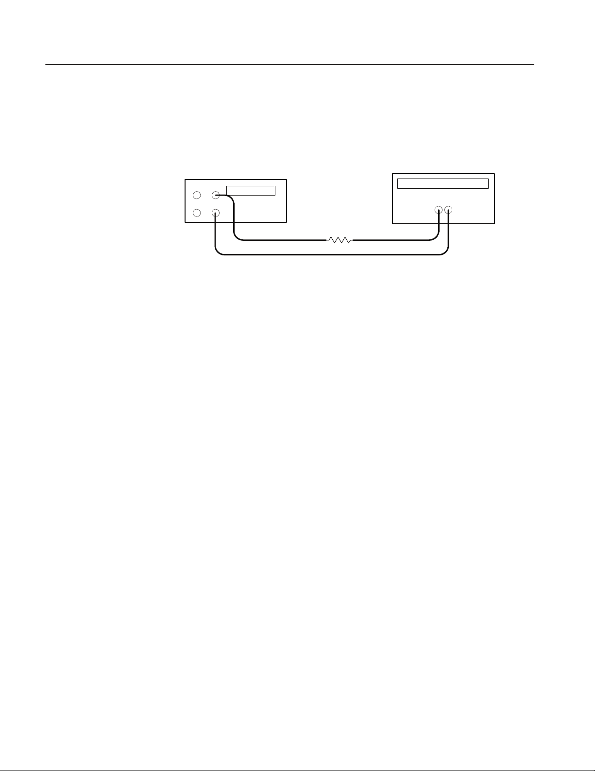
PS2520 and PS2521 Series Performance Verification
2. Ensure that the power supply output is disabled. Connect the Current Meter
and 27 Ω 100 W resistor to the front panel OUTPUT 1 terminals. See
Figure6fordetails.
Digital multimeter
--
COM
+
10 A
Resistor
Power supply
+
--
Figure 6: Constant current source test setup
3. Set the Current Meter to measure 2 amperes DC.
4. Press SHIFT
→ OUT 1; verify that the “1” indicator lights up on the display.
5. Set up the power supply as follows:
VOLTS SET 36 V
CURRENT SET 1.5 A
OVP SET 38.5 V
6. Press OUTPUT ON/OFF. Verify that the “OUT” indicator lights up on the
display.
30
7. Adjust the output of the Variac from 108 to 132 VAC (120 V range) or 198
to 242 VAC (220 V range). Verify that the Current Meter current variation is
≤0.003 A over the adjustment range.
8. Press OUTPUT ON/OFF. Verify that the “OUT” indicator turns off.
9. Press (SHIFT) OUT 2; verify that the “2” indicator lights up on the display.
10. Ensure that the power supply output is disabled. Remove the leads from the
front panel OUTPUT 1 terminals and connect them to the front panel
OUTPUT 2 terminals. Maintain the equipment configuration and polarities
shown in Figure 6.
11. Repeat steps 5 to 8 above.
Parallel Operation. Use the following steps to check the parallel mode output
accuracy.
1. Press SHIFT
→ OUT 2; verify that the “2” indicator lights up on the display.
Bench Test Instruments and Handheld Oscilloscopes Basic Service

PS2520 and PS2521 Series Performance Verification
2. Press SHIFT
→ PARA/INDEP to configure OUTPUT 1 and OUTPUT 2 for
parallel operation. Verify that the “PARA” indicator lights up on the display.
3. Set the Current Meter to measure 5 amperes DC.
4. Set up the power supply as follows:
VOLTS SET 36 V
CURRENT SET 3.0 A
OVP SET 38.5 V
5. Press OUTPUT ON/OFF. Verify that the “OUT” indicator lights up on the
display.
6. Adjust the output of the Variac from 108 to 132 VAC (120 V range) or 198
to 242 VAC (220 V range). Verify that the Current Meter current variation is
≤0.006 A over the adjustment range.
7. Press OUTPUT ON/OFF. Verify that the “OUT” indicator turns off.
8. Press SHIFT
→ PARA/INDEP to reconfigure the outputs for independent
operation. Verify that the “PARA ”indicator turns off.
Output 3. Use the following steps to check the OUTPUT 3 accuracy.
1. Press SHIFT
→ OUT 3; verify that the “3” indicator lights up on the display.
2. Ensure that the power supply output is disabled. Connect the Current Meter
and 2.2 Ω 50 W resistor to the front panel OUTPUT 3 terminals. See
Figure6fordetails.
3. Set up the power supply as follows:
VOLTS SET 6 V
CURRENT SET 3.0 A
OVP SET 7 V
4. Repeat steps 6 through 8 of the Outputs 1 and 2 procedure above.
This concludes the PS2520 and PS2520G performance verification procedures.
Bench Test Instruments and Handheld Oscilloscopes Basic Service
31

PS2520 and PS2521 Series Performance Verification
PS2521 and PS2521G Checks
To verify the performance and function of the PS2521 and PS2521G power
supplies, implement the following checks in sequential order. To verify the
performance and function of the PS2520 and PS2520G power supplies, see
page 9. The test equipment for all verification procedures is listed on page 8.
NOTE. To clear a memory location, enter “0” as the VOLTS SET and CURRENT
SET values; then save the “0” values to the desired memory location.
For a list of error code descriptions, see your User manual.
Basic Function
Complete the following procedures to verify basic instrument function.
Outputs 1, 2, and 3. Use the following steps to verify OUTPUT 1, OUTPUT 2,
and OUTPUT 3 basic function.
1. Press SHIFT
2. Set up the power supply as follows:
VOLTS SET 10 V
CURRENT SET 1 A
OVP SET 22 V
DELAY 3 s
3. Press SHIFT
location. Verify that the MEMORY, CURRENT (A), and VOLTS readouts
display the values listed in step 2 for memory location 01.
4. Reset the power supply as follows:
VOLTS SET 11 V
CURRENT SET 1.1 A
OVP SET 22 V
DELAY 3 s
→ OUT 1; verify that the “1” indicator lights up on the display.
→ STORE → 1 to store the above values in the memory 01
32
5. Press SHIFT
location. Verify that the MEMORY, CURRENT (A), and VOLTS readouts
display the values listed in step 4 for memory location 02.
6. Press SHIFT
7. Press RECALL LAST; verify that the readouts display the data stored in the
memory 02 location.
→ STORE → 2 to store the above values in the memory 02
→ RECALL; then enter 1.2 .
Bench Test Instruments and Handheld Oscilloscopes Basic Service

PS2520 and PS2521 Series Performance Verification
8. Press RECALL LAST again; verify that the readouts now display the data
stored in the memory 01 location.
9. Press RECALL NEXT; verify that the readouts display the data stored in the
memory 02 location.
10. Press OUTPUT ON/OFF. Verify that the “OUT” indicator lights up on the
display.
11. Press AUTO SEQ ON/OFF and verify that the “AUTO” indicator lights up
on the display. Verify that the front panel readouts alternately display the
memory 01 and memory 02 setups from steps 2 and 4 above, every three
seconds.
12. Press AUTO SEQ ON/OFF and OUTPUT ON/OFF. Verify that the “AUTO”
and “OUT” indicators turn off.
13. Press STEP SET. Set the VOLTS SET to 1.00 V.
14. Press VOLTS
and verify that as you attempt to decrease the voltage
below 0.00 V, “Err - 018” appears on the CURRENT (A) and VOLTS
readouts. The voltage should decrease in 1 volt steps on the VOLTS readout.
15. Press VOLTS
and verify that as you attempt to increase the voltage past
21.00 V, “Err - 016” appears on the readouts. The voltage should increase in
1 volt steps on the VOLTS readout.
16. Press STEP SET. Set the CURRENT SET to .1 A.
17. Press CURRENT
and verify that as you attempt to decrease the current
below 0.000 A, “Err - 019” appears on the readouts and the “C.C.” indicator
lights up on the display. The current should decrease in .1 ampere steps on
the CURRENT (A) readout.
18. Press CURRENT and verify that as you attempt to increase the current
past 2.500 A, “Err - 017” appears on the readouts. The current should
increase in .1 ampere steps on the CURRENT (A) readout.
To check the function of OUTPUT 2, press SHIFT
→ OUT 2. Verify that the “2”
indicator lights up on the display; then repeat steps 2 through 18 above.
To check the function of OUTPUT 3, press SHIFT
→ OUT 3. Verify that the “3”
indicator lights up on the display; then continue with the steps below.
19. Set up the power supply as follows:
VOLTS SET 5 V
CURRENT SET 4 A
OVP SET 7 V
DELAY 3 s
Bench Test Instruments and Handheld Oscilloscopes Basic Service
33

PS2520 and PS2521 Series Performance Verification
20. Press SHIFT
→ STORE → 1 to store the above values in the memory 01
location. Verify that the MEMORY, CURRENT (A), and VOLTS readouts
display the values listed in step 19 for memory location 01.
21. Reset the power supply as follows:
VOLTS SET 6 V
CURRENT SET 5 A
DELAY 3 s
22. Press SHIFT
→ STORE → 2 to store the above values in the memory 02
location. Verify that the MEMORY, CURRENT (A), and VOLTS readouts
display the values set in step 21 for memory location 02.
23. Repeat steps 6 through 12 above.
24. Press STEP SET. Set the VOLTS SET to 1 V.
25. Press VOLTS
and verify that as you attempt to decrease the voltage
below 0.00 V, “Err - 018” appears on the CURRENT (A) and VOLTS
readouts. The voltage should decrease in 1 volt steps on the VOLTS readout.
26. Press VOLTS
and verify that as you attempt to increase the voltage past
6.00 V, “Err - 016” appears on readouts. The voltage should increase in
1 volt steps on the VOLTS readout.
27. Press STEP SET. Set the CURRENT SET to .1 A.
28. Press CURRENT
and verify that as you attempt to decrease the current
below 0.000 A, “Err - 019” appears on the readouts and the “C.C.” indicator
lights. The current should decrease in .1 ampere steps on the CURRENT (A)
readout.
29. Press CURRENT
and verify that as you attempt to increase the current
past 5.100 A, “Err - 017” appears on the readouts. The current should
increase in .1 ampere steps on the CURRENT (A) readout.
OCP, Series, and Parallel Mode Indicators. Use the following steps to verify OCP,
series, and parallel output indicator function.
1. On the power supply front panel, press OCP ON/OF F to enable the OCP.
Verify that the “OCP” indicator lights up on the display.
2. Press OCP ON/OFF. Verify that the “OCP” indicator turns off.
3. Press SHIFT
→ SERIES/INDEP to configure the power supply outputs for
series operation. Verify that the “SERIES” indicator lights up on the display.
4. Press SHIFT
→ PARA/INDEP to configure the power supply outputs for
parallel operation. Verify that the “PARA” indicator lights up on the display.
34
Bench Test Instruments and Handheld Oscilloscopes Basic Service

PS2520 and PS2521 Series Performance Verification
Voltage Set A ccuracy
5. Press SHIFT
→ PARA/INDEP again to reconfigure the outputs for indepen-
dent operation. Verify that the “PARA” and “SERIES” indicators turn off.
Set GPIB. Use the following steps to check the GPIB address.
1. Press LOCAL.
2. Enter a GPIB address <0 to 30> and press
.
3. Press SHIFT → ADDRESS. Verify that the address entered in step 2 above
appears on the readout for about one second.
Complete the following procedures to verify voltage setting and readout
accuracy.
Outputs 1 and 2. Use the following steps to check the OUTPUT 1 and
OUTPUT 2 accuracy.
1. Press SHIFT
→ OUT 1; verify that the “1” indicator lights up on the display.
2. Set up the power supply as follows:
VOLTS SET 20 V
OVP SET 22 V
3. Press STEP SET. Set the VOLTS SET to 0.05 V.
4. Ensure that the power supply output is disabled. Configure the DVM to
measure 25 VDC across the front panel OUTPUT 1 (2) terminals.
5. Press OUTPUT ON/OFF. Verify that the “OUT” indicator lights up on the
display.
6. Verify that the DVM reads between 19.965 and 20.035 VDC.
7. Press VOLTS
or VOLTS to adjust the power supply output voltage
until the DVM reads 20.00 VDC.
8. Verify that the power supply VOLTS readout indicates between 19.965 and
20.035 V.
9. Press VOLTS SET. Set the power supply output voltage to 0.1 V.
10. Set the DVM to measure 1 VDC across the power supply OUTPUT 1 (2)
terminals.
11. Verify that the DVM reads between 0.0749 and 0.1250 VDC.
12. Press OUTPUT ON/OFF. Verify that the “OUT” indicator turns off.
Bench Test Instruments and Handheld Oscilloscopes Basic Service
35

PS2520 and PS2521 Series Performance Verification
13. Press SHIFT
→ OUT 2; verify that the “2” indicator lights up on the display.
14. Repeat steps 2 through 12 above to measure the OUTPUT 2 voltage setting
and readout accuracy .
Output 3. Use the following steps to check the OUTPUT 3 accuracy.
1. Press SHIFT
→ OUT 3; verify that the “3” indicator lights up on the display.
2. Set up the power supply as follows:
VOLTS SET 6 V
OVP SET 7 V
3. Press STEP SET. Set the VOLTS SET to 0.05 V.
4. Ensure that the power supply output is disabled. Configure the DVM to
measure 10 VDC across the power supply front panel OUTPUT 3 terminals.
5. Press OUTPUT ON/OFF. Verify that the “OUT” indicator lights up on the
display.
6. Verify that the DVM reads between 5.972 and 6.028 VDC.
7. Press VOLTS
or VOLTS to adjust the power supply output voltage
until the DVM reads 6.00 VDC.
8. Verify that the power supply VOLTS readout reads between 5.950 and
6.050 V.
9. Press VOLTS SET. Set the power supply output voltage to 0.1 V.
10. Set the DVM to measure 1 VDC across the power supply OUTPUT 3
terminals.
11. Verify that the DVM reads between 0.0749 and 0.1250 VDC.
12. Press OUTPUT ON/OFF. Verify that the “OUT” indicator turns off.
Series Operation. Use the following steps to check the series mode accuracy.
1. Press SHIFT
→ OUT 2; verify that the “2” indicator lights up on the display.
2. Set up the power supply as follows:
VOLTS SET 20 V
OVP SET 22 V
3. Press STEP SET. Set the VOLTS SET to 0.05 V.
36
Bench Test Instruments and Handheld Oscilloscopes Basic Service

PS2520 and PS2521 Series Performance Verification
4. Ensure that the power supply output is disabled. Configure the DVM to
measure 50 VDC across the front panel OUTPUT 2 (+) and OUTPUT 1 (--)
terminals.
5. Press SHIFT
→ SERIES/INDEP to configure OUTPUT 1 and OUTPUT 2
for series operation. Verify that the “SERIES” indicator lights up on the
display.
6. Press OUTPUT ON/OFF. Verify that the “OUT” indicator lights up on the
display.
7. Verify that the DVM reads between 39.930 and 40.070 VDC.
8. Press VOLTS
or VOLTS to adjust the power supply output voltage
until the DVM reads 40.000 VDC.
9. Verify that the power supply VOLTS readout indicates between 19.965 and
20.035 V.
10. Press VOLTS SET. Set the power supply output voltage to 0.1 V.
11. Set the DVM to measure 1 VDC across the power supply OUTPUT 2 (+)
and OUTPUT 1 (--) terminals.
12. Verify that the DVM reads between 0.1498 and 0.2500 VDC.
13. Press OUTPUT ON/OFF. Verify that the “OUT” indicator turns off.
Parallel Operation. Use the following steps to check the parallel mode accuracy.
1. Press SHIFT
→ OUT 2; verify that the “2” indicator lights up on the display.
2. Set up the power supply as follows:
VOLTS SET 20 V
OVP SET 22 V
3. Press STEP SET. Set the VOLTS SET to 0.05 V.
4. Ensure that the power supply output is disabled. Configure the DVM to
measure 25 VDC across the power supply front panel OUTPUT 2 terminals.
5. Press SHIFT
→ PARA/INDEP to configure OUTPUT 1 and OUTPUT 2 for
parallel operation. Verify that the “PARA” indicator lights up on the display.
6. Press OUTPUT ON/OFF. Verify that the “OUT” indicator lights up on the
display.
7. Verify that the DVM reads between 19.965 and 20.035 VDC.
8. Press VOLTS
or VOLTS to adjust the power supply output voltage
until the DVM reads 20.00 VDC.
Bench Test Instruments and Handheld Oscilloscopes Basic Service
37

PS2520 and PS2521 Series Performance Verification
9. Verify that the power supply VOLTS readout indicates between 19.965 and
20.035 V.
10. Press VOLTS SET. Set the power supply output voltage to 0.1 V.
11. Set the DVM to measure 1 VDC across the power supply OUTPUT 2
terminals.
12. Verify that the DVM reads between 0.0749 and 0.1250 VDC.
13. Press OUTPUT ON/OFF. Verify that the “OUT” indicator turns off.
Current Set Accuracy
14. Press SHIFT
→ PARA/INDEP to reconfigure the outputs for independent
operation. Verify that the “PARA” indicator turns off.
Complete the following procedures to verify current setting and readout
accuracy.
Outputs 1 and 2. Use the following steps to check the OUTPUT 1 and
OUTPUT 2 accuracy.
1. Press SHIFT
→ OUT 1; verify that the “1” indicator lights up on the display.
2. Set up the power supply as follows:
VOLTS SET 10 V
CURRENT SET 2.5 A
OVP SET 11 V
3. Press STEP SET. Set the CURRENT SET to 0.002 A.
4. Ensure that the power supply output is disabled. Configure the Current
Meter to measure 10 amperes DC across the front panel OUTPUT 1 (2)
terminals.
5. Press OUTPUT ON/OFF. Verify that the “OUT” indicator lights up on the
display.
38
6. Verify that the Current Meter reads between 2.485 and 2.515 A.
7. Press CURRENT
or CURRENT to adjust the power supply output
current until the Current Meter reads 2.500 A.
8. Verify that the power supply CURRENT (A) readout indicates between
2.485 and 2.515 A.
9. Press CURRENT S ET. Set the power supply output current to 0.1 A.
10. Verify that the Current Meter reads between 0.089 and 0.111 A.
11. Press OUTPUT ON/OFF. Verify that the “OUT” indicator turns off.
Bench Test Instruments and Handheld Oscilloscopes Basic Service

PS2520 and PS2521 Series Performance Verification
12. Press SHIFT
→ OUT 2; verify that the “2” indicator lights up on the display.
13. Repeat steps 2 through 11 above to measure the OUTPUT 2 current setting
and readout accuracy .
Output 3. Use the following steps to check the OUTPUT 3 accuracy.
1. Press SHIFT
→ OUT 3; verify that the “3” indicator lights up on the display.
2. Set up the power supply as follows:
VOLTS SET 6 V
CURRENT SET 5 A
OVP SET 7 V
3. Press STEP SET. Set the CURRENT SET to 0.002 A.
4. Ensure that the power supply output is disabled. Configure the Current
Meter to measure 10 amperes DC across the front panel OUTPUT 3
terminals.
5. Press OUTPUT ON/OFF. Verify that the “OUT” indicator lights up on the
display.
6. Verify that the Current Meter reads between 4.980 and 5.020 A.
7. Press CURRENT
or CURRENT to adjust the power supply output
current until the Current Meter reads 5.000 A.
8. Verify that the power supply CURR ENT (A) readout indicates between
4.980 and 5.020 A.
9. Press CURRENT S ET. Set the power supply output current to 0.1 A.
10. Verify that the Current Meter reads between 0.089 and 0.111 A.
11. Press OUTPUT ON/OFF. Verify that the “OUT” indicator turns off.
Parallel Operation. Use the following steps to the check parallel mode accuracy.
1. Press SHIFT
→ OUT 2; verify that the “2” indicator lights up on the display.
2. Set up the power supply as follows:
VOLTS SET 10 V
CURRENT SET 2.5 A
OVP SET 11 V
3. Press STEP SET. Set the CURRENT SET to 0.002 A.
Bench Test Instruments and Handheld Oscilloscopes Basic Service
39

PS2520 and PS2521 Series Performance Verification
4. Ensure that the power supply output is disabled. Configure the Current
Meter to measure 10 amperes DC across the power supply front panel
OUTPUT 2 terminals.
5. Press SHIFT
→ PARA/INDEP to configure OUTPUT 1 and OUTPUT 2 for
parallel operation. Verify that the “PARA” indicator lights up on the display.
6. Press OUTPUT ON/OFF. Verify that the “OUT” indicator lights up on the
display.
7. Verify that the Current Meter reads between 4.970 and 5.030 A.
8. Press CURRENT
or CURRENT to adjust the power supply output
current until the Current Meter reads 5.000 A.
9. Verify that the power supply CURRENT (A) readout indicates between
4.970 and 5.030 A.
10. Press CURRENT SET. Set the power supply output current to 0.1 A.
11. Verify that the Current Meter reads between 0.089 and 0.11 1 A.
12. Press OUTPUT ON/OFF. Verify that the “OUT” indicator turns off.
13. Press SHIFT
→ PARA/INDEP to reconfigure the outputs for independent
operation. Verify that the “PARA” indicator turns off.
14. Disconnect the Current Meter from the power supply output terminals.
Overvoltage
Protection Accuracy
Complete the following procedures to verify OVP (overvoltage protection)
accuracy.
Outputs 1 and 2. Use the following steps to check the OUTPUT 1 and
OUTPUT 2 accuracy.
1. Press SHIFT
→ OUT 1; verify that the “1” indicator lights up on the display.
2. Press OVP SET and set the OVP to 22.6 V. Verify that the power supply
readouts display the error message “Err - 065”.
3. Press OVP SET again and set the OVP to 22.5 V. Verify that the power
supply readouts display no error message.
4. Set up the power supply as follows:
VOLTS SET 18 V
CURRENT SET .1 A
OVP SET 20 V
5. Press STEP SET. Set the VOLTS SET to 0.02 V.
40
Bench Test Instruments and Handheld Oscilloscopes Basic Service

PS2520 and PS2521 Series Performance Verification
6. Press OUTPUT ON/OFF. Verify that the “OUT” indicator lights up on the
display.
7. Press VOLTS
to increase the power supply output voltage until the error
message “Err - 013” appears on the readouts. Verify that this event occurs
between 19.00 and 21.00 V.
8. Press SHIFT
→ OVP RESET.
9. Reset the output voltage to 18 V.
10. Repeat steps 6 through 9 above as necessary to determine the exact voltage.
11. Press OUTPUT ON/OFF. Verify that the “OUT” indicator turns off.
12. Press SHIFT
→ OUT 2; verify that the “2” indicator lights up on the display.
13. Repeat steps 2 through 11 above.
Parallel Operation. Use the following steps to check the parallel mode output
accuracy.
1. With the power supply still set to OUT 2, press SHIFT
→ PARA/INDEP to
configure OUTPUT 1 and OUTPUT 2 for parallel operation. Verify that the
“PARA” indicator lights up on the display.
2. Repeat steps 2 through 11 of the Outputs 1 and 2 procedure above.
3. Press SHIFT
→ PARA/INDEP to reconfigure the outputs for independent
operation. Verify that the “PARA” indicator turns off.
Output 3. Use the following steps to check the OUTPUT 3 accuracy.
1. Press SHIFT
→ OUT 3; verify that the “3” indicator lights up on the display.
2. Press OVP SET; set the OVP to 7.1 V. Verify that the power supply readouts
display the error message “Err - 065”.
3. Press OVP SET again; set the OVP to 7 V. Verify that power supply readouts
display no error message.
4. Set up the power supply as follows:
VOLTS SET 4 V
CURRENT SET .1 A
OVP SET 5 V
5. Press STEP SET. Set the VOLTS SET to 0.02 V.
6. Press OUTPUT ON/OFF. Verify that the “OUT” indicator lights up on the
display.
Bench Test Instruments and Handheld Oscilloscopes Basic Service
41

PS2520 and PS2521 Series Performance Verification
Constant Voltage
Load Accuracy
7. Press VOLTS
to increase the power supply output voltage until the error
message “Err - 013” appears on the readouts. Verify that this event occurs
between 4.3 and 5.7 V.
8. Press SHIFT
→ OVP RESET.
9. Reset the output voltage to 4 V.
10. Repeat steps 6 through 9 above as necessary to determine the exact voltage.
11. Press OUTPUT ON/OFF. Verify that the “OUT” indicator turns off.
Complete the following procedures to verify constant voltage load accuracy.
Outputs 1 and 2. Use the following steps to check the OUTPUT 1 and
OUTPUT 2 accuracy.
1. Press SHIFT
→ OUT 1; verify that the “1” indicator lights up on the display.
2. Ensure that the power supply output is disabled. Connect the Current Meter
and electronic load to the front panel OUTPUT 1 terminals. See Figure 7 for
details.
Digital multimeter
--
COM
+
10 A
Power supply
+
--
Electronic load
+--
Figure 7: Constant voltage load test setup
3. Set the DVM to measure 25 VDC.
4. Set up the power supply as follows:
VOLTS SET 20 V
CURRENT SET 2.55 A
OVP SET 22 V
5. Press OUTPUT ON/OFF. Verify that the “OUT” indicator lights up on the
display.
6. Enable the electronic load. Adjust the load until the power supply
CURRENT (A) readout indicates 2.500 A.
42
Bench Test Instruments and Handheld Oscilloscopes Basic Service

PS2520 and PS2521 Series Performance Verification
7. Record the DVM voltage (V1).
8. Turn off the electronic load and record the DVM voltage again (V2).
9. Verify that the difference between V1 and V2 is ≤6mV.
10. Press OUTPUT OFF. Verify that the “OUT” indicator turns off.
11. Ensure that the power supply output is disabled. Remove the leads from the
front panel OUTPUT 1 terminals and connect them to the OUTPUT 1
terminals on the rear of the instrument. Maintain the equipment configuration and polarities shown in Figure 7.
12. Repeat steps 5 through 8 above and verify that the difference between V1
andV2is≤3mV.
13. Press OUTPUT ON/OFF. Verify that the “OUT” indicator turns off.
14. Press SHIFT
→ OUT 2; verify that the “2” indicator lights up on the display.
15. Ensure that the power supply output is disabled. Connect the DVM and
electronic load to the front panel OUTPUT 2 terminals. Maintain the
equipment configuration and polarities shown in Figure 7.
16. Repeat steps 4 through 10 above.
17. Ensure that the power supply output is disabled. Remove the leads from the
front panel OUTPUT 2 terminals and connect them to the rear panel
OUTPUT 2 terminals. Maintain the equipment configuration and polarities
shown in Figure 7.
18. Repeat steps 5 through 8 above and verify that the difference between V1
andV2is≤3mV.
19. Press OUTPUT ON/OFF. Verify that the “OUT” indicator turns off.
20. Disconnect the DVM and electronic load from the instrument.
Series Operation. Use the following steps to check the series mode output
accuracy.
1. With the power supply set to OUT 2, press SHIFT
→ SERIES/INDEP to
configure OUTPUT 1 and OUTPUT 2 for series operation. Verify that the
“SERIES” indicator lights up on the display.
2. Ensure that the power supply output is disabled. Connect the DVM and
electronic load to the front panel OUTPUT 2 (+) and OUTPUT 1 (--)
terminals. Maintain the equipment configuration and polarities shown in
Figure 7.
3. Perform steps 5 through 8 of the Outputs 1 and 2 procedure above.
Bench Test Instruments and Handheld Oscilloscopes Basic Service
43

PS2520 and PS2521 Series Performance Verification
4. Verify that the difference between V1 and V2 is ≤50 mV.
5. Press OUTPUT ON/OFF. Verify that the “OUT” indicator turns off.
6. Ensure that the power supply output is disabled. Remove the leads from the
front panel OUTPUT 2 and OUTPUT 1 terminals and connect them to the
rear panel OUTPUT 2 (+) and OUTPUT 1 (--) terminals. Maintain the
equipment configuration and polarities shown in Figure 7.
7. Repeat steps 5 through 8 of the Outputs 1 and 2 procedure above and verify
that the difference between V1 and V2 is ≤50 mV.
8. Press OUTPUT ON/OFF. Verify that the “OUT” indicator turns off.
9. Disconnect the DVM and electronic load from the instrument.
Parallel Operation. Use the following steps to check the parallel mode output
accuracy.
1. Press SHIFT
→ PARA/INDEP to configure OUTPUT 1 and OUTPUT 2 for
parallel operation. Verify that the “PARA” indicator lights up on the display.
2. Ensure that the power supply output is disabled. Connect the DVM and
electronic load to the front panel OUTPUT 2 terminals. Maintain the
equipment configuration and polarities shown in Figure 7.
3. Set the DVM to measure 25 VDC.
4. Set up the power supply as follows:
VOLTS SET 20 V
CURRENT SET 5.1 A
OVP SET 22 V
5. Press OUTPUT ON/OFF. Verify that the “OUT” indicator lights up on the
display.
6. Enable the electronic load. Adjust the load until the power supply
CURRENT (A) readout indicates 5.000 A.
7. Record the DVM voltage (V1).
8. Turn off the electronic load and record the DVM voltage again (V2).
9. Verify that the difference between V1 and V2 is ≤6mV.
44
10. Press OUTPUT ON/OFF. Verify that the “OUT” indicator turns off.
11. Ensure that the power supply output is disabled. Remove the leads from the
front panel OUTPUT 2 terminals and connect them to the OUTPUT 2
terminals on the rear of the instrument. Maintain the equipment configuration and polarities shown in Figure 7.
Bench Test Instruments and Handheld Oscilloscopes Basic Service

PS2520 and PS2521 Series Performance Verification
12. Repeat steps 5 through 8 above and verify that the difference between V1
andV2is≤3mV.
13. Press OUTPUT ON/OFF. Verify that the “OUT” indicator turns off.
14. Press SHIFT
→ PARA/INDEP to reconfigure the outputs for independent
operation. Verify that the “PARA” indicator turns off.
15. Disconnect the DVM and electronic load from the instrument.
Output 3. Use the following steps to check the OUTPUT 3 accuracy.
1. Press SHIFT
→ OUT 3; verify that the “3” indicator lights up on the display.
2. Ensure that the power supply output is disabled. Connect the DVM and
electronic load to the front panel OUTPUT 3 terminals. Maintain the
equipment configuration and polarities shown in Figure 7.
3. Set the DVM to measure 10 VDC.
4. Set up the power supply as follows:
VOLTS SET 6 V
CURRENT SET 5.1 A
OVP SET 7 V
5. Press OUTPUT ON/OFF. Verify that the “OUT” indicator lights up on the
display.
6. Enable the electronic load. Adjust the load until the power supply
CURRENT (A) readout indicates 5.000 A.
7. Record the DVM voltage (V1).
8. Turn off the electronic load and record the DVM voltage again (V2).
9. Verify that the difference between V1 and V2 is ≤6mV.
10. Press OUTPUT ON/OFF. Verify that the “OUT” indicator turns off.
11. Ensure that the power supply output is disabled. Remove the leads from the
front panel OUTPUT 3 terminals and connect them to rear panel OUTPUT 3
terminals. Maintain the equipment configuration and polarities shown in
Figure 7.
12. Repeat steps 5 through 8 above and verify that the difference between V1
andV2is≤3mV.
13. Press OUTPUT ON/OFF. Verify that the “OUT” indicator turns off.
14. Disconnect the DVM and electronic load from the instrument.
Bench Test Instruments and Handheld Oscilloscopes Basic Service
45

PS2520 and PS2521 Series Performance Verification
Constant Voltage
Source Accuracy
Complete the following procedures to verify constant voltage source accuracy.
Outputs 1 and 2. Use the following steps to check the OUTPUT 1 and
OUTPUT 2 accuracy.
1. Set up the Variac. Connect the power supply AC input to the Variac variable
output. Allow 20 minutes for the power supply to warm up and stabilize.
2. Ensure that the power supply output is disabled. Connect the DVM and
electronic load to the front panel OUTPUT 1 terminals. See Figure 8 for
details.
Digital multimeter
--
COM
+
10 A
Power supply
+
--
Electronic load
+--
Figure 8: Constant voltage source test setup
3. Set the DVM to measure 25 VDC.
4. Press SHIFT
→ OUT 1; verify that the “1” indicator lights up on the display.
5. Set up the power supply as follows:
VOLTS SET 20 V
CURRENT SET 2.55 A
OVP SET 22 V
6. Press OUTPUT ON/OFF. Verify that the “OUT” indicator lights up on the
display.
7. Enable the electronic load. Adjust the load until the power supply
CURRENT (A) readout indicates 2.500 A.
8. Adjust the output of the Variac from 108 to 132 VAC (120 V range) or 198
to 242 VAC (220 V range). Verify that the DVM readout changes ≤0.003
volts over the adjustment range.
9. Press OUTPUT ON/OFF and disable the electronic load.
10. Press SHIFT
→ OUT 2; verify that the “2” indicator lights up on the display.
46
Bench Test Instruments and Handheld Oscilloscopes Basic Service

PS2520 and PS2521 Series Performance Verification
11. Ensure that the power supply output is disabled. Remove the leads from the
front panel OUTPUT 1 terminals and connect them to the front panel
OUTPUT 2 terminals. Maintain the equipment configuration and polarities
shown in Figure 8.
12. Repeat steps 5 through 9 above.
Series Operation. Use the following steps to check the series mode output
accuracy.
1. Press SHIFT
→ SERIES/INDEP to configure OUTPUT 1 and OUTPUT 2
for series operation. Verify that the “SERIES” indicator lights up on the
display.
2. Ensure that the power supply output is disabled. Connect the DVM and
electronic load to the front panel OUTPUT 2 (+) and OUTPUT 1 (--)
terminals. Maintain the equipment configuration and polarities shown in
Figure 8.
3. Repeat steps 5 through 9 of the Outputs 1 and 2 procedure above.
Parallel Operation. Use the following steps to check the parallel mode output
accuracy.
1. Press SHIFT → PARA/INDEP to configure OUTPUT 1 and OUTPUT 2 for
parallel operation. Verify that the “PARA” indicator lights up on the display.
2. Ensure that the power supply output is disabled. Connect the DVM and
electronic load to the front panel OUTPUT 2 terminals. Maintain the
equipment configuration and polarities shown in Figure 8.
3. Set the DVM to measure 25 VDC.
4. Set up the power supply as follows:
VOLTS SET 20 V
CURRENT SET 5.1 A
OVP SET 22 V
5. Press OUTPUT ON/OFF. Verify that the “OUT” indicator lights up on the
display.
6. Enable the electronic load. Adjust the l oad until the power supply
CURRENT (A) readout indicates 5.000 A.
7. Adjust the output of the Variac from 108 to 132 VAC (120 V range) or 198
to 242 VAC (220 V range). Verify that the DVM readout changes ≤0.003
volts over the adjustment range.
Bench Test Instruments and Handheld Oscilloscopes Basic Service
47

PS2520 and PS2521 Series Performance Verification
8. Press OUTPUT ON/OFF. Verify that the “OUT” indicator turns off; then
disable the electronic load.
9. Press SHIFT → PARA/INDEP to reconfigure the outputs for independent
operation. Verify that the “PARA” indicator turns off.
Output 3. Use the following steps to check the OUTPUT 3 accuracy.
1. Press SHIFT
2. Ensure that the power supply output is disabled. Connect the DVM and
electronic load to the front panel OUTPUT 3 terminals. Maintain the
equipment configuration and polarities shown in Figure 8.
3. Set up the power supply as follows:
VOLTS SET 6 V
CURRENT SET 5.1 A
OVP SET 7 V
4. Press OUTPUT ON/OFF. Verify that the “OUT” indicator lights up on the
display.
5. Enable the electronic load. Adjust the load until the power supply
CURRENT (A) readout indicates 5.000 A.
6. Adjust the output of the Variac from 108 to 132 VAC (120 V range) or 198
to 242 VAC (220 V range). Verify that the DVM readout changes ≤0.003
volts over the adjustment range.
7. Press OUTPUT ON/OFF; then disable the electronic load.
8. Disconnect the DVM and electronic load from the instrument.
→ OUT 3; verify that the “3” indicator lights up on the display.
48
Constant Voltage
Ripple and Noise
Accuracy
Complete the following procedures to verify constant voltage ripple and noise
accuracy.
Outputs 1 and 2. Use the following steps to check the OUTPUT 1 and
OUTPUT 2 accuracy.
1. Press SHIFT
2. Ensure that the power supply output is disabled. Connect the oscilloscope
and 27 Ω 75 W resistor to the front panel OUTPUT 1 terminals. See
Figure9fordetails.
→ OUT 1; verify that the “1” indicator lights up on the display.
Bench Test Instruments and Handheld Oscilloscopes Basic Service
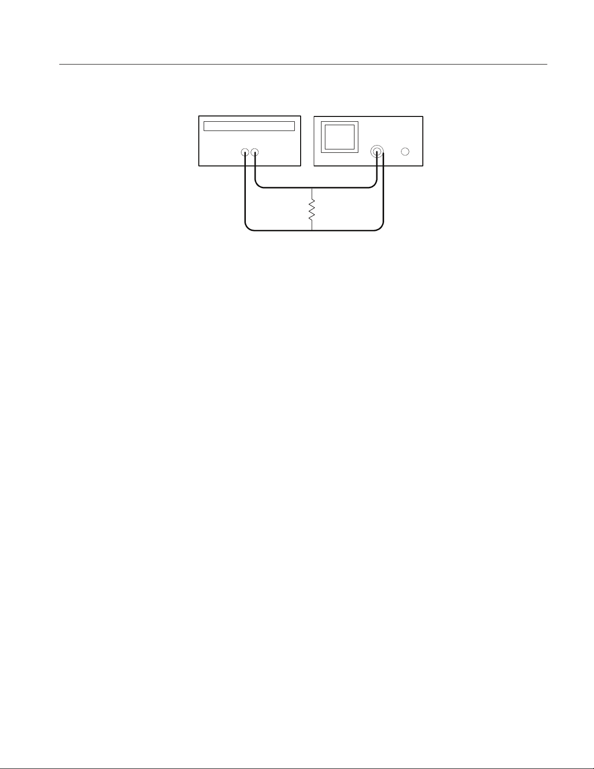
PS2520 and PS2521 Series Performance Verification
Power supply
+
--
Oscilloscope
Resistor
Figure 9: Constant voltage ripple and noise test setup
3. Set up the oscilloscope to measure 100 mV
(AC coupled).
p-p
4. Set up the power supply as follows:
VOLTS SET 36 V
CURRENT SET 2.55 A
OVP SET 38 V
5. Press OUTPUT ON/OFF. Verify that the “C.V.” indicator lights up on the
display.
6. Using a 0.1 F ceramic capacitor to decouple the test points, adjust the
oscilloscope and verify that the noise is ≤30 mV
p-p
.
7. Set up the oscilloscope to LINE trigger source. Adjust the output of the
Variac from 108 to 132 VAC (120 V range) or 198 to 242 VAC (220 V
range). Verify that the ripple changes ≤3mV
over the adjustment range.
p-p
8. Press OUTPUT ON/OFF. Verify that the “OUT” indicator turns off.
9. Press SHIFT
→ OUT 2; verify that the “2” indicator lights up on the display.
10. Ensure that the power supply output is disabled. Remove the leads from the
front panel OUTPUT 1 terminals and connect them to the front panel
OUTPUT 2 terminals. Maintain the equipment configuration and polarities
shown in Figure 9.
11. Repeat steps 4 through 8 above.
Outputs 3. Use the following steps to check the OUTPUT 3 accuracy.
1. Press SHIFT
→ OUT 3; verify that the “3” indicator lights up on the display.
Bench Test Instruments and Handheld Oscilloscopes Basic Service
49

PS2520 and PS2521 Series Performance Verification
2. Ensure that the power supply output is disabled. Connect the oscilloscope
and 2.2 Ω 50 W resistor to the front panel OUTPUT 3 terminals. See
Figure9fordetails.
3. Set up the power supply as follows:
VOLTS SET 6 V
CURRENT SET 5.1 A
OVP SET 7 V
4. Repeat steps 5 through 8 of the Outputs 1 and 2 procedure above.
5. Remove the Variac from the test setup and repower the instrument. Allow 20
minutes for the power supply to warm-up and stabilize before the next check.
Constant Current Load
and Overcurrent
Protection Accuracy
Complete the following procedures to verify constant current load and overcurrent protection accuracy .
Outputs 1 and 2. Use the following steps to check the OUTPUT 1 and
OUTPUT 2 accuracy.
1. Press SHIFT
→ OUT 1; verify that the “1” indicator lights up on the display.
2. Ensure that the power supply output is disabled. Connect the Current Meter
and electronic load to the front panel OUTPUT 1 terminals. See Figure 10
for details.
Digital multimeter
--
COM
+
10 A
Power supply
+
--
Electronic load
+--
Figure 10: Constant current load test setup
50
3. Set the Current Meter to measure 5 amperes DC.
4. Set up the power supply as follows:
VOLTS SET 20 V
CURRENT SET 2.5 A
OVP SET 22 V
Bench Test Instruments and Handheld Oscilloscopes Basic Service

PS2520 and PS2521 Series Performance Verification
5. Press OUTPUT ON/OFF. Verify that the “OUT” indicator lights up on the
display.
6. Enable the electronic load. Adjust the load until the “C.C.” indicator lights
up on the power supply display.
7. Record the Current Meter current reading (I1).
8. Press OUTPUT ON/OFF. Verify that the “OUT” indicator turns off.
9. Ensure that the power supply output is disabled. Remove the wire connect-
ing the power supply OUTPUT (+) terminal to the electronic load (+)
terminal.
10. Move the electronic load (--) connection to the power supply OUTPUT (+)
terminal.
11. Press OUTPUT ON/OFF. Verify that the “OUT” indicator lights up on the
display.
12. Record the Current Meter current reading again (I2).
13. Verify that the difference between (I1) and (I2) is ≤0.003 A.
14. Press OUTPUT ON/OFF. Verify that the “OUT” indicator turns off.
15. Press OCP ON/OFF; verify that the “OCP” indicator lights up on the
display.
16. Press OUTPUT ON/OFF. Verify that the “OUT” indicator lights up on the
display.
17. Verify that the power supply readouts display the error message “Err - 012”.
18. Press OUTPUT ON/OFF. Verify that the “OUT” indicator turns off.
19. Press OCP ON/OFF to return the power supply to normal operation. Verify
that the “OCP” indicator turns off.
20. Press SHIFT
→ OUT 2; verify that the “2” indicator lights up on the display.
21. Ensure that the power supply output is disabled. Connect the Current Meter
and electronic load to the front panel OUTPUT 2 terminals. Maintain the
equipment configuration and polarities shown in Figure 10.
22. Repeat steps 4 through 18 above.
Bench Test Instruments and Handheld Oscilloscopes Basic Service
51

PS2520 and PS2521 Series Performance Verification
Parallel Operation. Use the following steps to check the parallel mode output
accuracy.
1. With the power supply set to OUT 2, press SHIFT → PARA/INDEP to
configure OUTPUT 1 and OUTPUT 2 for parallel operation. Verify that the
“PARA” indicator lights up on the display.
2. Set the Current Meter to measure 10 amperes DC.
3. Set up the power supply as follows:
VOLTS SET 20 V
CURRENT SET 5.0 A
OVP SET 22 V
4. Repeat steps 5 through 14 of the Outputs 1 and 2 procedure above but verify
that the difference between (I1) and (I2) is ≤0.006 A.
5. Repeat steps 15 through 18 of the Outputs 1 and 2 procedure above.
Constant Current
Source Accuracy
6. Press SHIFT
→ PARA/INDEP to reconfigure the outputs for independent
operation. Verify that the “PARA” indicator turns off.
Output 3. Use the following steps to check the OUTPUT 3 accuracy.
1. Press SHIFT
→ OUT 3; verify that the “3” indicator lights up on the display.
2. Ensure that the power supply output is disabled. Connect the Current Meter
and electronic load to the front panel OUTPUT 3 terminals. Maintain the
equipment configuration and polarities shown in Figure 10.
3. Set up the power supply as follows:
VOLTS SET 6 V
CURRENT SET 5.0 A
OVP SET 7 V
4. Repeat steps 5 through 18 of the Outputs 1 and 2 procedure above.
5. Disconnect the Current Meter and electronic load from the instrument.
Complete the following procedures to verify constant current source accuracy .
52
Outputs 1 and 2. Use the following steps to check the OUTPUT 1 and
OUTPUT 2 accuracy.
1. Set up the Variac. Connect the power supply AC input to the Variac variable
output. Allow 20 minutes for the power supply to warm up and stabilize.
Bench Test Instruments and Handheld Oscilloscopes Basic Service

PS2520 and PS2521 Series Performance Verification
2. Ensure that the power supply output is disabled. Connect the Current Meter
and 27 Ω 75 W resistor to the front panel OUTPUT 1 terminals. See
Figure 11 for details.
Digital multimeter
--
COM
+
10 A
Resistor
Power supply
+
--
Figure 11: Constant curr e nt source test setup
3. Set the Current Meter to measure 5 amperes DC.
4. Press SHIFT
→ OUT 1; verify that the “1” indicator lights up on the display.
5. Set up the power supply as follows:
VOLTS SET 20 V
CURRENT SET 2.5 A
OVP SET 22 V
6. Press OUTPUT ON/OFF. Verify that the “OUT” indicator lights up on the
display.
7. Adjust the output of the Variac from 108 to 132 VAC (120 V range) or 198
to 242 VAC (220 V range). Verify that the Current Meter current variation is
≤0.003 A over the adjustment range.
8. Press OUTPUT ON/OFF. Verify that the “OUT” indicator turns off.
9. Press SHIFT
→ OUT 2; verify that the “2” indicator lights up on the display.
10. Ensure that the power supply output is disabled. Remove the leads from the
front panel OUTPUT 1 terminals and connect them to the front panel
OUTPUT 2 terminals. Maintain the equipment configuration and polarities
shown in Figure 11.
11. Repeat steps 5 to 8 above.
Parallel Operation. Use the following steps to check the parallel mode output
accuracy.
1. Press SHIFT
→ OUT 2; verify that the “2” indicator lights up on the display.
Bench Test Instruments and Handheld Oscilloscopes Basic Service
53

PS2520 and PS2521 Series Performance Verification
2. Press SHIFT
→ PARA/INDEP to configure OUTPUT 1 and OUTPUT 2 for
parallel operation. Verify that the “PARA” indicators light up on the display.
3. Set the Current Meter to measure 5 amperes DC.
4. Set up the power supply as follows:
VOLTS SET 20 V
CURRENT SET 5.0 A
OVP SET 22 V
5. Press OUTPUT ON/OFF. Verify that the “OUT” indicator lights up on the
display.
6. Adjust the output of the Variac from 108 to 132 VAC (120 V range) or 198
to 242 VAC (220 V range). Verify that the Current Meter current variation is
≤0.006 A over the adjustment range.
7. Press OUTPUT ON/OFF. Verify that the “OUT” indicator turns off.
8. Press SHIFT
→ PARA/INDEP to reconfigure the outputs for independent
operation. Verify that the “PARA” indicator turns off.
Output 3. Use the following steps to check the OUTPUT 3 accuracy.
1. Press SHIFT
→ OUT 3; verify that the “3” indicator lights up on the display.
2. Ensure that the power supply output is disabled. Connect the Current Meter
and 2.2 Ω 50 W resistor to the front panel OUTPUT 3 terminals. See
Figure 11 for details.
3. Set up the power supply as follows:
VOLTS SET 6 V
CURRENT SET 5.0 A
OVP SET 7 V
4. Repeat steps 6 through 8 of the Outputs 1 and 2 procedure above.
This concludes the PS2521 and PS2521G performance verification procedures.
54
Bench Test Instruments and Handheld Oscilloscopes Basic Service

PS2520 and PS2521 Series Adjustment Procedures
This section contains procedures to adjust PS2520 and PS2521 Series power
supplies. If your instrument fails a performance requirement, use these procedures to return it to factory specifications.
In this section you will find the following information:
H A list of the adjustments
H A list of test equipment needed to make the adjustments
H Instructions on how to prepare instruments for adjustment
H Step-by-step adjustment procedures
The procedures in this section do not verify performance. To confirm that your
power supply meets factory specifications, implement the procedures in the
PS2520 and PS2521 Series Performance Verification section.
List of Adjustments
Use the adjustments listed in Table 8 to return PS2520 Series power supplies to
factory calibration.
Table 8: PS2520 and PS2521 series adjustments
Full Calibration
Output 1
Output 2
Parallel Output: Current Offset
Parallel Output: Current Full Scale
Output 3
Partial Calibration
Voltage Offset
Voltage Full Scale
Current Offset
Current Full Scale
Overvoltage Protection: Offset
Overvoltage Protection: Full Scale
Bench Test Instruments and Handheld Oscilloscopes Basic Service
55

PS2520 and PS 2521 Series Adjustment Procedures
Table 8: PS2520 and PS2521 series adjustments(cont.)
Parallel Output: Current Offset
Parallel Output: Current Full Scale
Test Equipment
To ensure accurate adjustments, use the test equipment specified in Table 9.
Alternative test equipment must meet or exceed the intended minimum
requirements specified in Table 9. If you substitute equipment, you may need to
modify the procedures.
NOTE. Before making any adjustment, warm up the test equipment according to
the manufacturer’s recommendations.
Table 9: Adjustment test equipment
Description Minimum requirements Example product
Digital Volt Meter (DVM) DC volts accuracy: ±0.01% Agilent 34401A
Digital Current Meter DC amphere accuracy: ±0.02% Fluke 45
Preparation for Adjustment
Perform the adjustment procedures on an as-needed basis. If a power supply
section fails a performance requirement, or if a section is replaced or repaired,
adjust only that section. Adjusting individual sections of the instrument rarely
affects its total performance.
The following guidelines apply to all adjustments:
H Verify that the line voltage selector (instrument rear) is set to the correct
voltage. If you must change the selector setting, disconnect the AC power
before altering the setting.
H Remove the instrument cover for the voltage full-scale calibrations only.
H Plug in and warm up the instrument for at least ten minutes. A thirty minute
warm-up period is required if the instrument has been exposed to a high-humidity or high-condensing environment.
56
H Perform the adjustments in a 22_ to 24_ C(71_ to 75
ment with a relative humidity of 75% or less.
Bench Test Instruments and Handheld Oscilloscopes Basic Service
_ F) ambient environ-
 Loading...