

Page 1

xx
BB1000-NA, BB1000-EU & BB1000-UK
Breakout Box for Tektronix Power Analyzers
ZZZ
Instruction Manual
Register now!
Click the following link to protect your product.
► www.tektronix.com/register
www.tektronix.com
*P071323900*
071-3239-00
Page 2

Copyright © Tektronix. All rights reserved. Licensed software products are owned by Tektronix or its subsidiaries or suppliers, and are
protected by na
tional copyright laws and international treaty provisions.
Tektronix pro
previously published material. Specifications and price change privileges reserved.
TEKTRONIX and TEK are registered trademarks of Tektronix, Inc.
ducts are covered by U.S. and foreign patents, issued and pending. Information in this publication supersedes that in all
Contacting Tektronix
Tektronix, Inc.
14150 SW Karl Braun Drive
P.O. Box 500
Beaverton, OR 97077
USA
For product i nformation, sales, service, and technical support:
In North America, call 1-800-833-9200.
Worldwide, visit www.tektronix.com to find contacts in your area.
Page 3

Warranty
Tektronix warrants that this product will be free from defects in materials and workmanship for a period of one (1) year from the date of
shipment. If any such product proves defective during this warranty period, Tektronix, at its option, either will repair the defective
product without charge for parts and labor, or will provide a replacement in exchange for the defective product. Parts, modules and
replacement products used by Tektronix for warranty work may be new or reconditioned to like new performance. All replaced
parts, modules and products become the property of Tektronix.
In order to obtain service under this warranty, Customer must notify Tektronix of the defect before the expiration of the warranty period
and make suitable arrangements for the performance of service. Customer shall be responsible for packaging and shipping the
defective product to the service center designated by Tektronix, with shipping charges prepaid. Tektronix shall pay for the return of the
product to Customer if the shipment is to a location within the country in which the Tektronix service center is located. Customer shall
be responsible for paying all shipping charges, duties, taxes, and any other charges for p roducts returned to any other locations.
This warranty shall not apply to any defect, failure or damage caused by improper use or improper or inadequate maintenance and
care. Tektronix shall not be obligated to furnish service under this warranty a) to repair damage resulting from attempts by personnel
other than Tektronix representatives to inst all, repair or service the product; b) to repair damage resulting from improper use or
connection to incompatible equipment; c) to repair any damage or malfunction caused by the use of non-Tektronix supplies; or
d) to service a product that has been modified or integrated with other products when the effect of such modification or integration
increases the time or difficulty of servicing the product.
THIS WARRANTY IS GIVEN BY TEKTR ON IX WITH RES PEC T TO THE PRODUCT IN LIEU OF ANY OTHER WARRANTIES,
EXPRESS OR IMPLIED. TEKTRONIX AND ITS VENDORS DISCLAIM ANY IMPLIED WARRANTIES OF MERCHANTABILITY OR
FITNESS FOR A PARTICULAR PURPOSE. TEKTRONIX' RESPONSIBILITY TO REPAIR OR REPLACE DEFECTIVE PRODUCTS
IS THE SOLE AND EXCLUSIVE REMEDY PROVIDED TO THE CUSTOMER FOR BREACH OF THIS WARRANTY. TEKTRONIX
AND ITS VENDORS WILL NOT BE LIABLE FOR ANY INDIRECT, SPECIAL, INCIDENTAL, OR CONSEQUENTIAL DAMAGES
IRRESPECTIVE OF WHETHER TEKTRONIX OR THE VENDOR HAS ADVANCE NOTICE OF THE POSSIBILITY OF SUCH
DAMAGES.
[W2 – 15AUG04]
Page 4

Page 5

Table of Contents
Important safety information .......................................................................................................... iii
General safe
Service safety summary ......................................................................................................... v
Terms in this manual ...... . . . ...... . . . .... . . . . ...... . . . ...... . . . .... . . . . ...... . . . ...... . . . .... . . . . . ..... . . . . ..... . . . ...... . . . .... vi
Symbols and
Compliance information .............................................................................................................. vii
Safety compliance............................................................................................................... vii
Environme
Preface................................................................................................................................. x
BB1000-xx breakout box . . .... . . . . ...... . . . .... . . . . .... . . . . .... . . . . ...... . . ...... . . . .... . . . . .... . . . . ...... . . . .... . . . . .... . . . . .... . . ... 1
Models............................................................................................................................ 1
Connecting the breakout box . . . ...... . . . ...... . . . .... . . . . .... . . . . ...... . . . .... . . . . ...... . . . ...... . . . .... . . . . ...... . . . .... . . . . ... 2
Measuring currents of 500mA or more ......................................................................................... 3
Measurin
Specifications..................................................................................................................... 5
ty summary......................................................................................................... iii
terms on the product ...... . . . ...... . . . ...... . . . ...... . . . ...... . . . .... . . . . ...... . . . ...... . . . .... . . . . ...... . . . ...... vi
ntal considerations ................................................................................................... ix
g currents of 500 mA or less .......................................................................................... 4
Table of Content
s
Instruction Manual i
Page 6

Table of Content
s
ii Instruction Manual
Page 7

Important safet
y information
Important saf
This manual contains information and warnings that must be followed by the user for safe operation and to keep the
product in a safe condition.
To safely perform service on this product, additional information is provided at the end of this section. (See page v,
Service safety summary.)
ety information
General safety summary
Use the prod
or any products connected to it. Carefully read all instructions. Retain these instructions for future reference.
Comply with local and national safety codes.
For correct and safe operation of the product, it is essential that you follow generally accepted safety procedures in addition
to the safety precautions specified in this manual.
The product is designed to be used by trained personnel only.
Only qualified personnel who are aware of the hazards involved should remove the cover for repair, maintenance, or
adjustme
Before us
This pro
uct only as specified. Review the following safety precautions to avoid injury and prevent damage to this product
nt.
e, always check the product with a known source to be sure it is operating correctly.
duct is not intended for detection of hazardous voltages.
Use pers
While us
component manuals for warnings and cautions related to operating the system.
When incorporating this equipment into a system, the safety of that system is the responsibility of the assembler of the system.
onal protective equipment to prevent shock and arc blast injury where hazardous live conductors are exposed.
ing this product, you may need to access other parts of a larger system. Read the safety sections of the o ther
To avoid fire or personal injury
Use proper power cord. Use only the power cord specified for this product and certified for the country of use.
Do not use the provided power cord for other products.
nd the product.
Grou
shock, the grounding conductor must be connected to earth ground. Before making connections to the input or output
terminals of the product, make sure that the product is properly grounded.
Power disconnect. The power cord disconnects the product from the power source. See instructions for the location.
Do not position the equipment so that it is difficult to operate the power cord; it must remain accessible to the user at all
times to allow for quick disconnection if needed.
Connect and disconnect properly. Do not connect or disconnect probes or test leads while they are connected
to a voltage source.
Use only insulated voltage probes, test leads, and adapters supplied with the product, or indicated by Tektronix to be
itable for the product.
su
This product is grounded through the grounding conductor of the power cord. To avoid electric
Instruction Manual iii
Page 8

Important safet
Observe all terminal ratings. To avoid fire or shock hazard, observe all ratings and markings on the product. Consult
the product man
Category (CAT) rating and voltage or current rating of the lowest rated individual component of a product, probe, or
accessory. Use caution when using 1:1 test leads because the probe tip voltage is directly transmitted to the product.
Do not apply a potential to any terminal, including the common terminal, that exceeds the maximum rating of that terminal.
Do not operate without covers. Do not operate this product with covers or panels removed, or with the c ase open.
Hazardous voltage exposure is possible.
Avoid exposed circuitry. Do not touch exposed connections and components when power is present.
Do not operate with suspected failures. If you suspect that there is damage to this product, have it inspected by
qualified service personnel.
Disable the product if it is damaged. Do not use the product if it is damaged or operates incorrectly. If in doubt about safety of
the product, turn it off and disconnect the power cord. Cl early mark the product to prevent its further operation.
Before use, inspect v oltage probes, test leads, and accessories for mechanical damage and replace when damaged. Do not
use probes or test leads if they are damaged, if there is exposed metal, or if a wear indicator shows.
y information
ual for further ratings information before making connections to the product. Do not exceed the Measurement
Examine the exte
Use only specified replacement parts.
rior of the product before you use it. Look for cracks or missing pieces.
Use proper fuse. Use only the fuse type and rating specified for this product.
Do not operate in wet/damp conditions. Be aware that condensation may occur if a unit is moved from a c old to a
warm environment.
Do not operate in an explosive atmosphere.
Keep product surfaces clean and dry.
Remove the input signals before you clean the product.
Provide proper ventilation. Refer to the installation instructions in the manual for details on installing the product
so it has proper ventilation.
Slots and openings are provided for ventilation and shoul
into any of the openings.
d never be covered or otherwise obstructed. Do not push objects
Provide a safe working environment. Be sure your work area meets applicable ergonomic standards. Consult
with an ergonomics professional to avoid stress injuries.
Use only the Tektronix rackmount hardware specified for this product.
Probes and test leads
Before connecting probes or test leads, connect the power cord from the power connector to a properly grounded power
let.
out
Keep fingers behind the finger guards on the probes.
Remove all probes, test leads and accessories that are not in use.
Use only correct Measurement Category (CAT), voltage, temperature, altitude, and amperage rated probes, test leads,
and adapters for any measurement.
iv Instruction Manual
Page 9

Important safet
y information
Beware of high voltages. Understand the voltage ratings for the probe you are using and do not exceed those ratings.
Connect and disconnect properly. De-energize the circuit under test before connecting or disconnecting the current
probe.
Connect the probe reference lead to earth ground only.
Do not connect a current probe to any wire that carries voltages above the current probe voltage rating.
Inspect the p
defects in the probe body, accessories, or cable jacket). Do not use if damaged.
robe and accessories.
Servicesafetysummary
The Service safety summary section contains additional information required to safely perform service on the product. Only
qualified personnel should perform service procedures. Read this Service safety summary and the General safety summary
before performing any service procedures.
To avoid electric shock. Do not touch exposed connections.
Do not service alone. Do not perform internal service or adjustments of this product unless another person capable of
rendering first aid and resuscitation is present.
Disconn
power before removing any covers or panels, or opening the case for servicing.
ect power.
Use care when servicing with power on. Dangerous voltages or currents may exist in this product. Disconnect
power, remove battery (if applicable), and disconnect test leads before removing protective panels, soldering, or replacing
components.
y safety after repair.
Verif
To avoid electric shock, switch off the product power and disconnect the power cord from the m ains
Before each use, inspect probe and accessories for damage (cuts, tears, or
Always recheck ground continuity and mains dielectric strength after performing a repair.
Instruction Manual v
Page 10
Important safet
y information
Terms in this manual
These terms may appear in this manual:
WARNING. Warning statements identify conditions or practices that could result in injury or loss of life.
CAUTION. Caution statements identify conditions or practices that could result in damage to this product or other property.
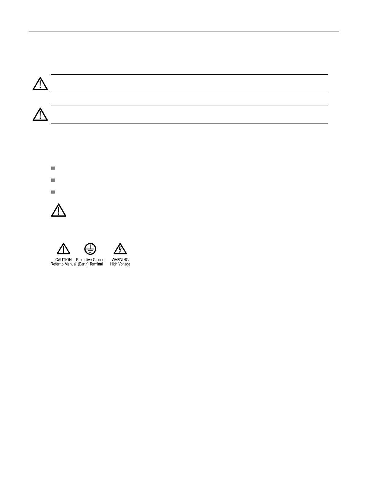
Symbols and terms on the product
These terms may appear on the product:
DANGER indicates an injury hazard immediately accessible as you read the m arking.
WARNING indicates an injury hazard not immediately accessible as you read the marking.
CAUTION indicates a hazard to property including the product.
When this symbol is marked on the product, be sure to consult the manual to find out the nature o f the
potential hazards and any actions which have to be taken to avoid them. (This symbol may also be used to
refer the user to ratings
The following symbol(s) may appear on the product:
in the manual.)
vi Instruction Manual
Page 11

Compliance info
rmation
Compliance in
This section lists the safety and environmental standards with which the instrument complies.
Safety compliance
This section lists the safety standards with which the product complies and other safety compliance information.
EU declaration of conformity – low voltage
Compliance was demonstrated to the following specification as listed in the Official Journal of the European Union:
Low Voltage Directive 2006/95/EC.
EN 61010-1. Safety Requirements for Electrical Equipment for Measurement, C ontrol, and Laboratory Use – Part
1: General Requirements.
EN 61010-2-030. Safety Requirements for Electrical Equipment for M easurement, Control, and Laboratory Use – Part
2-030: Particular requirements for testing and measuring circuits.
U.S. nationally recognized testing laboratory listing (BB1000-NA only)
UL 61010-1. Safety Requirements for Electrical Equipment for Measurement, Control, and Laboratory Use – Part
1: General Requirements.
formation
UL 61010-2-030. Safety Requirements for Electrical Equipment for Measurement, Control, and Laboratory Use – Part
Particular requirements for testing and measuring circuits.
2-030:
Canadian certification (BB1000-NA only)
CAN/CSA-C22.2 No. 61010-1. Safety Requirements for Electrical Equipment for Measurement, Control, and Laboratory
Use – Part 1: General Requirements.
CAN/CSA-C22.2 No. 61010-2-030. Safety Requirements for Electrical Equipment for Measurement, C ontrol, and
Laboratory U se – Part 2-030: Particular requirements for testing and measuring circuits.
Additional compliances
61010-1. Safety Requirements for Electrical Equipment for Measurement, Control, and Laboratory Use – Part
IEC
1: General Requirements.
IEC 61010-2-030. Safety Requirements for Electrical Equipment for Measurement, Control, and Laboratory Use – Part
2-030: Particular requirements for testing and measuring circuits.
uipment type
Eq
Test and measuring equipment.
Instruction Manual vii
Page 12

Compliance info
Safety class
Class 1 – grounded product.
Pollution degree descrip tions
A measure of the contaminants that could occur in the envir onment around and within a product. Typically the internal
environment
for which they are rated.
Pollution degree 1. No pollution or only dry, nonconductive pollution occurs. Products in this category are generally
encapsulated, hermetically sealed, or located in clean rooms.
Pollution degree 2. Normally only dry, nonconductive pollution occurs. Occasionally a temporary conductivity that is
caused by c
occurs only when the product is out of service.
Pollution degree 3. Conductive pollution, or dry, nonconductive pollution that becomes conductive due to condensation.
These are sheltered locations where neither temperature nor humidity is controlled. The area is protected from direct
sunshine
Pollutio
outdoor locations.
rmation
inside a product is considered to be the same as the external. Products should be used only in the environment
ondensation must be expected. This location is a typical office/home environment. Temporary condensation
, rain, or direct wind.
n degree 4. Pollution that generates persistent conductivity through conductive dust, rain, or snow. Typical
Pollution degree rating
Pollution degree 2 (as defined in IEC 61010-1). Rated for indoor, dry location use only.
Measurement and overvoltage category descriptions
Measurement terminals on this product may be rated for measuring mains voltages from one or more of the following
ories (see specific ratings marked on the product and in the manual).
categ
ory II. Circuits directly connected to the building wiring at utilization points (socket outlets and similar points).
Categ
gory III. In the building wiring and distribution system.
Cate
gory IV. At the source of the electrical supply to the building.
Cate
NOTE. Only mains power supply circuits have an overvoltage category rating. Only measurement circuits have a
measurement category rating. Other circuits within the product do not have either rating.
Mains overvoltage category rating
Overvoltage category II (as defined in IEC 61010-1).
viii Instruction Manual
Page 13

Environmental considerations
This section provides information about the environmental impact of the product.
Product end-of-life handling
Observe the following guidelines when recycling an instrument or component:
Equipment recycling. P roduction of this equipment required the extraction and use of natural resources. The equipment
may contain substances that could be harmful to the environment or human health if improperly handled at the product’s
end of life. To avoid release of such substances into the environment and to reduce the use of natural resources, we
encourage you to recycle this product in an appropriate system that will ensure that most of the materials are reused
or recycled appropriately.
This symbol indicates that this product complies with the applicable European Union requirements according
to Directives 2002/96/EC and 2006/66/EC on waste electrical and electronic equipment (WEEE) and
batteries. For information about recycling options, check the Support/Service section of the Tektronix Web
site (www.tektronix.com).
Restriction of hazardous substances
Compliance info
rmation
This product is classified as an industrial monitoring and control instrument accessory, and is not required to comply with the
substance restrictions of the recast RoHS Directive 2011/65/EU until July 22, 2017.
Instruction Manual ix
Page 14

Preface
Preface
This document describes how to connect and use the following models of the BB1000 breakout box:
Model BB1000-NA: 120 V North America
Model BB1000-EU: 240 V Europe
Model BB1000-UK: 240 V United Kingdom
x Instruction Manual
Page 15

BB1000-xx breakout box
The simplest and safest way to make a connection to your device under test is to use the Tektronix BB1000-xx breakout
box. The breakout box provides a line output socket to power the device under test, and 4 x 4 mm sockets for direct
connection to the Tektronix power analyzer terminals.
Models
There are three versions of the breakout box, differing by the type of line socket:
Model BB1000-NA: 120 V North America
Model BB1000-EU: 240 V Europe
Model BB1000-UK: 240 V United Kingdom
All models include a 10 Amp power cord and instructions.
BB1000-xx break
out box
Figure 1: BB1000-NA breakout box
1. IEC line input connector – connect the line cord of the breakout box to this connector.
2. Line output socket – plug the power cord from the device under test into this connector.
3. Voltage connections – the VHI and VLO
load conditions of the device under test. To take measurements in low-power (s tandby mode), the VHI and VLO
connections are used.
4. Current connections – the AHI and ALO terminals typically connect to the AHI and ALO inputs on the power analyzer,
for currents from 1 A to 20 A. For currents less than 500 mA, the AHI terminal of the breakout box is connected to the
A1A (1 Amp) input of the power analyzer.
Instruction Manual 1
connections are used for measuring power consumption under normal
Load
Source
Page 16

BB1000-xx break
out box
Connecting the breakout box
CAUTION. For p
inputs on a measurement system, the breakout box should only be used with Tektronix power analyzers.
CAUTION. The current drawn by the device under test must not exceed the current rating of the BB1000-xx power cord
(10 Amps). The maximu
rotection against mismatched connections, for example, connecting the voltage connection to the current
m c urrent drawn by the device under test cannot exceed 10 A
RMS
.
Connection sequence
1. Using the test leads provided with the Tektronix power analyzer, make the voltage and current connections between the
breakout box and the input jacks on the power analyzer. Typical connections are shown for the PA1000 and PA4000
power analyzers on the following pages. (See Figure 3 on page 3.) (See Figure 4 on page 4.)
Figure 2: Connection and power-on sequence
2. Plug the power cord from the device under test into the receptacle on the breakout box.
3. Connect the breakout box power cord from the line source to the breakout box line input connector.
4. Power on the device under test and begin taking measurements.
NOTE. The AHI and ALO connections must be made for the device under test to power on.
2 Instruction Manual
Page 17

Measuring currents of 500 mA or more
Under most test conditions, the requirement is to measure the voltage across the device under test. The figure below shows
how to make these connections.
BB1000-xx break
out box
Figure 3: Typical connection for currents above 500 mA
Instruction Manual 3
Page 18

BB1000-xx break
out box
Measuring currents of 500 mA or less
For standby power measurements, the current and power in the voltmeter circuit can be significant when compared to current
being measured. For standby measurements the voltage is connected on the supply side of the current shunt. The figure
below shows how to make the connections to the breakout box and analyzer for low current measurements.
Figure 4: Typical connection for currents of 500 mA or less
4 Instruction Manual
Page 19

Specifications
Table 1: Electrical specifications
Characteristic BB1000-NA BB1000-EU BB1000-UK
Operating voltage (line
input/outpu
Maximum lin
under test)
Maximum vol
and either VLO terminals
Maximum cu
and ALO terminals
Table 2: Physical specifications (all models)
Characteristic
Dimensions
Weigh
t)
Height
Width
Depth
t
e current draw (device
tage between VHI
rrent between AHI
BB1000-xx break
120 VAC 240 VAC 240 VAC
10 A
RMS
10 A
RMS
10 A
RMS
125 VAC 240 VAC 240 VAC
10 A
RMS
10 A
RMS
10 A
RMS
62 mm (2.4 in)
160 mm (6.3 in)
90 mm (3.5 in)
375 gms (13.2 oz)
out box
Table 3: Environmental specifications (all models)
Characteristic
Temperature
Operating 0 to 40 °C (32 to 104 °F)
operating
Non
idity, maximum operating
Hum
Altitude, maximum operating
–20 to +60 °C (–4 to 140 °F)
80% for temperatures up to 31 °C (88 °F), decreasing linearly to 50 % relative
humidity at 40 °C (104 °F)
2000 m (6560 ft)
Instruction Manual 5
 Loading...