

Page 1

BARack
xx
ZZZ
Rackmount kit
Instructions
*P071350300*
071-3503-00
Page 2

Page 3

xx
BARack
ZZZ
Rackmount kit
Instructions
Register now!
Click the following link to protect your product.
► www.tek.com/register
www.tek.com
071-3503-00
Page 4

Copyright © Tektronix. All rights reserved. Licensed software products are owned by Tektronix or its subsidiaries
or suppliers, and are protected by national copyright laws and international treaty provisions.
Tektronix products are covered by U.S. and foreign patents, issued and pending. Information in this publication
supersedes that in all previously published material. Specifications and price change privileges reserved.
TEKTRONIX and TEK are registered trademarks of Tektronix, Inc.
Contacting Tektronix
Tektronix, Inc.
14150 SW Karl Braun Drive
P.O. Box 50 0
Beaverto
USA
For product information, sales, service, and technical support:
n, OR 97077
In North America, call 1-800-833-9200.
Worldwide, visit www.tek.com to find contacts in your area.
Page 5

Warranty
Tektronix warrants that this p roduct will be free from defects in materials and workmanship for a period of one (1)
year from the date of shipment. If any such product proves defective during this warranty period, Tektronix, at its
option, either will repair the defective product without charge for parts and labor, or will provide a replacement
in exchange for the defective product. Parts, modules and replacement products used by Tektronix for warranty
work may be n
the property of Tektronix.
ew or reconditioned to like new performance. All replaced parts, modules and products become
In order to o
the warranty period and make suitable arrangements for the performance of service. Customer shall be responsible
for packaging and shipping the defective product to the service center designated by Tektronix, with shipping
charges prepaid. Tektronix shall pay for the return of the product to Customer if the shipment is to a location within
the country in which the Tektronix service center is located. Customer shall be responsible for paying all shipping
charges, duties, taxes, and any other charges for products returned to any other locations.
This warranty shall not apply to any defect, failure or damage caused by improper use or improper or inadequate
maintenance and care. Tektronix shall not be obligated to furnish service under this warranty a) to repair damage
result
b) to repair damage resulting from improper use or connection to incompatible equipment; c) to repair any damage
or malfunction caused by the use of non-Tektronix supplies; or d) to service a product that has b een modified or
integrated with other products when the effect of such modification or integration increases the time or difficulty
of servicing the product.
THIS WARRANTY IS GIVEN BY TEKTRONIX WITH RESPECT TO THE PRODUCT IN LIEU OF ANY
OTHER WARRANTIES, EXPRESS OR IMPLIED. TEKTRONIX AND ITS VENDORS DISCLAIM ANY
IMPLIED WARRANTIES OF MERCHANTABILITY OR FITNESS FOR A PARTICULAR PURPOSE.
TRONIX' RESPONSIBILITY TO REPAIR OR REPLACE DEFECTIVE PRODUCTS IS THE SOLE
TEK
AND EXCLUSIVE REMEDY PR OVIDED TO THE CUSTOMER FOR BREACH OF THIS WARRANTY.
TEKTRONIX AND ITS VENDORS WILL NOT BE LIABLE FOR ANY INDIRECT, SPECIAL, INCIDENTAL,
OR CONSEQUENTIAL DAMAGES IRRESPECTIVE OF WHETHER TEKTRONIX OR THE VENDOR HAS
ADVANCE NOTICE OF THE POSSIBILITY OF SUCH DAMAGES.
[W2 – 15AUG04]
btain service under this warranty, Customer must notify Tektronix of the defect before the expiration of
ing from attempts by personnel other than Tektronix representatives to install, repair or service the product;
Page 6

Page 7

Table of Contents
Service safety summary............................................................................................ ii
Introduction ......................................................................................................... 1
Warranted characteristics ..................................................................................... 2
Clearance r
Installation instructions ............................................................................................ 5
Minimum tool and equipment list................................. ................................ ........... 5
Assemble the rack slides and brackets and install them in the rack cabinet............................. 6
Install the rack tray assembly into the rack cabinet ... ................................ .................... 10
Replace the front and rear feet on the instrument (Optional) .................. .......................... 10
Install
equirements ....................................................................................... 3
the instrument onto the rack tray...................................... .............................. 12
BA Rackmount kit instructions i
Page 8

Service safety summary
Service safet
ysummary
The Service s
safely perform service on the product. Only qualified personnel should perform
service procedures. Read this Service safety summary and the General safety
summary before performing any service procedures.
To avoid electric shock. Do not touch exposed connections.
Do not service alone. Do not perform internal service or adjustments of this
product unless another person capable of rendering first aid and resuscitation is
present.
Disconnect power. To avoid electric shock, switch off the product power and
disconn
panels, or opening the case for servicing.
Use care when servicing with power on. Dangerous voltages or currents may exist
in this product. Disconnect power, remove battery (if applicable), and disconnect
test leads before removing protective panels, soldering, or replacing components.
Verify safety after repair. Always recheck ground continuity and mains dielectric
strength after performing a repair.
afety summary section contains additional information required to
ect the power cord from the mains power before removing any covers or
ii BA Rackmount kit instructions
Page 9

Introduction
This document describes the installation of the BARACK rackmount kit for the
BA1500 and BA1600 products. The kit instructions are a collection of parts that,
once installed, configure the instrument for mounting into a standard 19-inch
instrument rack. An additional pair of extended length brackets are available for
mounting th
e instrument into a deep rack.
The following table and figure show the parts list for the rackmount kit.
Table 1: Pa
Item
number Quantity Part number Description
-
-
1 1 650-5976-xx
2 4 210-1596–xx
3 4 212-0004-xx
4 8 212-0260-xx
5
6 4 220-0337-xx Nut bar strip, 10-32 THD x3
7
8 2 348-2257-0xx Foot, locating, short rear
9 2 407
10 1 351-1139-xx
rts list
1
1 071-3503
4 212-0577-xx
2 348-2256-xx
BARACK Rackmount kit: BERTScope Series, consisting of the following items:
-xx
-5608-xx
Technica
Rackmou
Flat was
Screw,
Screw
Screw
Foot, locating, short front
Bra
Sli
l m anual: Instructions, this document
nt kit; B A1500/BA1600 series, preassembled
her, #12 x 0.5 outer diameter X 0.12 thick
mach; 8-32 x 0.312, PNH, Steel, zinc plated, T20 TORX
, mach; 10-32 x 0.375, PNH, Steel, zinc plated, T25 TORX
, mach; 10-32 x 0.625, TRH, Steel, zinc plated head, Phillips
cket, slide, extension, 7.48 in.
de assemblies, telescoping, two (2) front and two (2) rear brackets, with hardware
BA Rackmount kit instructions 1
Page 10

Introduction
Figure 1: Rackmount kit parts
Warranted characteristics
When the instrument is installed according to the instructions in this document,
rack-mounted instrument meets all warranted requirements listed in the
the
instrument specification except for those listed in Environmental Requirements.
truments mounted using methods other than those described in these
Ins
instructions may not meet their warranted requirements.
e Specifications in the user manual that apply to your instrument.
Se
Cooling air enters from the bottom-front and both sides. You must provide
dequate cool air to meet the ambient temperature requirements.
a
2 BA Rackmount kit instructions
Page 11

Introduction
Cleara
nce requirements
Figure 2: Instrument cooling
The rack in which the rack-adapted instrument is mounted must provide the
following clearance requirements:
A minimum of 10.5 inches (266.7 mm) of vertical space
A minimum of 19 inches (482.6 mm) between the left and right front rails of
the rack
A minimum depth of 25 inches (635 mm)
CAUTION. Failure to adhere to the clearance requirements can result in
overheating and cause instrument faults or failure. Air temperature at the
strument’s intake air vents must be maintained within the specified ambient
in
temperature range (+10 °C to +35 °C) during instrument operation. Always
adhere to the clearance requirements to provide the rack-mounted instrument with
enough clearance for air circulation and accommodation of the power cord,
cables, and mounting hardware.
BA Rackmount kit instructions 3
Page 12

Introduction
Figure 3: Instrument dimensions with clearance requirements in the rack
4 BA Rackmount kit instructions
Page 13

Installation instructions
This section c ontains the procedures needed to rack mount a BERTScope
instrument. The following steps are involved in the installation process:
Install the slide bracket kit and hardware to the rack.
Install the rack tray into the rack cabinet.
Replace the front and rear feet on the instrument (Optional)
Install the instrument onto the rack tray.
Installation instructions
Attach re
secure the instrument in place.
Minimum tool and equipment list
The following table lists the readily-available tools for the installation process.
Table 2: Tools required for rackmount installation
Name Description
No. 2 Ph
T-15 T
T-20 T
T-25
These instructions are for personnel who are familiar with servicing the product.
Contact your local Tektronix Service Center or Tektronix Factory Service for
installation information.
illips or Pozidriv tip
orx tip
orx tip
Torx tip
maining hardware to the instrument and rack assembly and then
Phillips or Pozidriv-driver tip for number 2 screw heads
Torx®-driver tip for T-15 size screw heads
Torx®-driver tip for T-20 size screw heads
Torx®-driver tip for T-25 size screw heads
BA Rackmount kit instructions 5
Page 14
Installation instructions
Assemble the rack slides and brackets and install them in the rack cabinet
Complete the following steps to remove the outer member of the rack slides
from the pre-assembled rack tray and install the rack slides with the brackets in
the rack cabinet.
1. Locate the pre-assembled rack tray from the kit contents (Item 1) and place it
on an open and clean working surface.
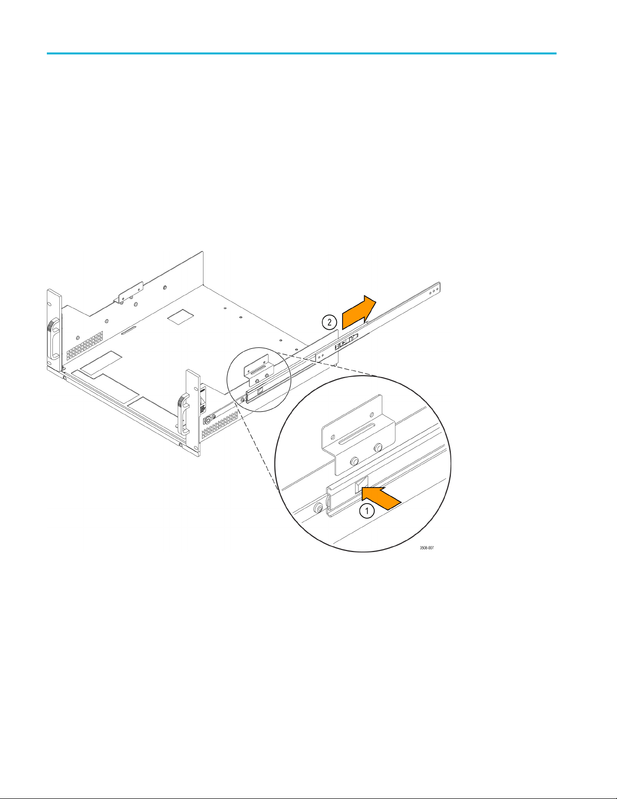
2. Refer to the following figure and remove the outer members of the rack slide
assemblies from both sides of the pre-assembled rack tray. (First push the
button latch near the bottom rear edge of each rack slide assembly to disengage
the rack s
lide from the rack tray. Then remove the rack slide assembly.)
Figure 4: Removing the rack slides from the rack tray
3. Set the rack tray aside and place the rack slides on the work surface to install
he front and rear brackets.
t
6 BA Rackmount kit instructions
Page 15

Installation instructions
4. Locate one of th
the Bracket kit.
5. Refer to Step 1
bracket as shown.
e nut bars from the kit (Item 7) and one of the brackets from
in the following figure and install the nut bar inside the
Figure 5: Install the nut bar inside one of the front brackets and then secure the bracket assembly to the front of
the rac
kslide.
6. Using
7. Determine whether you need to install the rear rack slide extension brackets
NOTE. The following steps and figures assume that you are installing the short
rear brackets. The steps for installing either set of brackets are the same. If
you are installing the extension brackets, use the hardware from the Bracket kit
secure them to the slides.
to
the hardware from the Bracket kit, secure the bracket assembly to the
rack slide as shown. (Install the two screws through the rectangular hole in
the inner rack slide.)
(Item 11) for deep racks or install the short rear brackets (from the Bracket kit).
BA Rackmount kit instructions 7
Page 16

Installation instructions
8. RefertoStep1i
bracket as shown.
Figure 6: Install the nut bar inside one of the rear brackets and then secure the bracket assembly to the end of
the rack slide.
9. Using the hardware from the Bracket kit, secure the bracket assembly to the
ide as shown.
rack sl
n the following figure and install the nut bar inside the
8 BA Rackmount kit instructions
Page 17

Installation instructions
10. Complete the fo
Refer to the following figure as needed.
llowing steps to install the rack slides in the rack cabinet.
Figure 7: Installing the rack slides to the rack cabinet
a. Use two machine screws (Item 4) to secure one of the rack slide
assemblies to the re ar of the rack cabinet.
b. Use two machine screws (Item 4) to secure the rack slide assembly to
the front of the rack cabinet.
c. Repeat the above steps to install the other rack slide assembly in the rack
cabinet.
BA Rackmount kit instructions 9
Page 18

Installation instructions
Install the rack tray assembly into the rack cabinet
Complete the following steps to install the rack tray assembly into the rack cabinet:
1. Grab the rack tray assembly and slide it into rack slides in the cabinet as
shown in the following figure.
e 8: Slide the rack tray assembly into the rack slides in the rack cabinet
Figur
2. Push
the rack tray into the cabinet until it locks in place.
Replace the front and rear feet on the instrument (Optional)
here is no instrument installed directly below the rack tray, you can s kip these
If t
steps.
an instrument is installed directly below the rack tray, there will not be enough
If
vertical clearance between the rack tray and the instrument. To avoid the clearance
problems, you need to replace the front and rear feet of the BA instrument with
those provided with the kit instructions.
10 BA Rackmount kit instructions
Page 19

Installation instructions
The feet need to
NOTE. To replace the feet, remove the covers from the chasis and replace the
feet secured to the bottom of the covers.
CAUTION. Many components within the chassis are susceptible to static
discharge damage. To avoid damaging the instrument, observe standard handling
precautions for static-sensitive devices while servicing the chassis.
Always wear a grounded wrist strap, or equivalent, while servicing the chassis.
The circuit boards and cables can be damaged if you incorrectly install the covers.
Make sure that you do not damage a ny circuit boards or cables when you slide the
chassis into the covers.
be replaced before installing the BA instrument into the rack.
BA Rackmount kit instructions 11
Page 20

Installation instructions
Install the instrument onto the rack tray
Complete the following procedures to install the instrument onto the rack tray.
Refer to the figure for an overview of the final installation process. (See Figure 9.)
Figure 9: Final installation steps
WARNING. To prevent the instrument from tipping or dropping onto the installers,
or more people should install the instrument into the rack cabinet.
two
After completing the installation procedure, the installers should verify that the
instrument and the rack cabinet will not tip forward while the instrument is in
the extended position.
Do not leave the instrument extended in the rack when finished accessing the
rear panel.
12 BA Rackmount kit instructions
Page 21

Installation instructions
1. Pull the rack tr
2. Remove the handles from both sides of the instrument and secure them to the
optional stor
just removed.
3. With the hel
extended rack tray, making sure that the feet of the instrument fit into the
holes on the bottom of the rack tray and the brackets on the sides of the rack
tray line up with screw holes of the handles that you just removed.
4. Locate the four T-20 Torx screws from the parts lists (Item 4) and install two
of the screws on each side of the instrument into holes where the handles
used to be.
NOTE. The remaining steps in this document secure the rack tray to the rack
cabinet
instrument.
5. Connect the instrument power cord to the rear of the instrument and any
6. Push the rack tray all of the way into the rack cabinet.
. Be sure to connect the power cord and any cables to the rear of the
cables that may be required for certain instrument configurations.
ay out of the rack cabinet until it locks in place.
age location on rear of the rack tray using the screws that you
p of another individual, carefully place the instrument on the
7. Locate two pairs of 10-32 Phillips screws (Item 5) and washers (Item 3) from
the kit. Install them on one of the sides of the instrument through the rack kit
side plates and into the rack; repeat for the other side of the instrument.
End of Document
BA Rackmount kit instructions 13
 Loading...