

Page 1

User Manual
AW V G 1
Wideband Video Generator
070-9051-02
This document applies to firmware version 2.0
and above.
www.tektronix.com
Page 2

Copyright © Tektronix, Inc. All rights reserved.
Tektronix products are covered by U.S. and foreign patents, issued and pending. Information in this publication supercedes
that in all previously published material. Specifications and price change privileges reserved.
Tektronix, Inc., P.O. Box 500, Beaverton, OR 97077
TEKTRONIX and TEK are registered trademarks of Tektronix, Inc.
Page 3

WARRANTY
Tektronix warrants that the products that it manufactures and sells will be free from defects in materials and workmanship
for a period of one (1) year from the date of shipment. If a product proves defective during this warranty period, Tektronix,
at its option, either will repair the defective product without charge for parts and labor, or will provide a replacement in
exchange for the defective product.
In order to obtain service under this warranty, Customer must notify Tektronix of the defect before the expiration of the
warranty period and make suitable arrangements for the performance of service . Customer shal l be responsible for
packaging and shipping the defective product to the service center designated by Tektronix, with shipping charges prepaid.
Tektronix shall pay for the return of the product to Customer if the shipment is to a location within the country in which the
Tektronix service center is located. Customer shall be responsible for paying all shipping charges, duties, taxes, and any
other charges for products returned to any other locations.
This warranty shall not apply to any defect, failure or damage caused by improper use or improper or inadequate
maintenance and care. Tektronix shall not be obligated to furnish service under this warranty a) to repair damage resulting
from attempts by personnel other than Tektronix representatives to install, repair or service the product; b) to repair
damage resulting from improper use or connection to incompatible equipment; c) to repair any damage or malfunction
caused by the use of non-Tektronix supplies; or d) to service a product that has been modified or integrated with other
products when the effect of such modification or integration increases the time or difficulty of servicing the product.
THIS W ARRANTY IS GIVEN BY TEKTRONIX IN LIEU OF ANY OTHER W ARRANTIES, EXPRESS OR
IMPLIED. TEKTRONIX AND ITS VENDORS DISCLAIM ANY IMPLIED WARRANTIES OF
MERCHANTABILITY OR FITNESS FOR A PARTICULAR PURPOSE. TEKTRONIX’ RESPONSIBILITY TO
REPAIR OR REPLACE DEFECTIVE PRODUCTS IS THE SOLE AND EXCLUSIVE REMEDY PROVIDED TO
THE CUSTOMER FOR BREACH OF THIS WARRANTY. TEKTRONIX AND ITS VENDORS WILL NOT BE
LIABLE FOR ANY INDIRECT, SPECIAL, INCIDENTAL, OR CONSEQUENTIAL DAMAGES IRRESPECTIVE
OF WHETHER TEKTRONIX OR THE VENDOR HAS ADVANCE NOTICE OF THE POSSIBILITY OF SUCH
DAMAGES.
Page 4

Service Assurance
If you have not already purchased Service Assurance for this product, you may do so at any time during the product’s
warranty period. Service Assurance provides Repair Protection and Calibration Services to meet your needs.
Repair Protection extends priority repair services beyond the product’s warranty period; you may purchase up to three
years of Repair Protection.
Calibration Services provide annual calibration of your product, standards compliance and required audit documentation,
recall assurance, and reminder notification of scheduled calibration. Coverage begins upon registration; you may purchase
up to five years of Calibration Services.
Service Assurance Advantages
H Priced well below the cost of a single repair or calibration
H Avoid delays for service by eliminating the need for separate purchase authorizations from your company
H Eliminates unexpected service expenses
For Information and Ordering
For more information or to order Service Assurance, contact your Tektronix representative and provide the information
below. Service Assurance may not be available in locations outside the United States of America.
Name VISA or Master Card number and expiration
Company date or purchase order number
Address Repair Protection (1,2, or 3 years)
City, State, Postal code Calibration Services (1,2,3,4, or 5 years)
Country Instrument model and serial number
Phone Instrument purchase date
Page 5

Table of Contents
Getting Started
Operating Basics
General Safety Summary vii..........................................
Service Safety Summary ix..........................................
Preface xi........................................................
Contacting Tektronix x.............................................
Getting Started 1--1............................................
Product Description 1--1..............................................
Accessories 1--2.....................................................
Configuration 1--2...................................................
Functional Check 1--3................................................
Functional Overview 2--1.......................................
Outputs 2--2........................................................
Input 2--2..........................................................
Online Help 2--2.....................................................
Operating Procedures 2--3......................................
Equipment Hookup 2--3...............................................
Power On and Select the Module 2--4....................................
Output Signal 2--5...................................................
Enable/Disable the Module Output 2--5...............................
Select the Output Signal 2--6.......................................
Active Signal Parameters 2--9..........................................
Video Parameters 2--11.............................................
Zone Plate Test Signal 2--14.........................................
Module Parameters 2--17...............................................
Timing 2--18.....................................................
Syntax and Commands
Syntax 3--1...................................................
Programming Model 3--1..............................................
Addressing Module Test Signals 3--1.................................
Command Arguments 3--1.........................................
Argument Example 3--2...........................................
SCPI Commands and Queries 3--3......................................
Functional Command Groups 3--5...............................
MMemory 3--5......................................................
Output 3--5.........................................................
Sense 3--6..........................................................
Source 3--6.........................................................
OUTPut Subsystem 3--9........................................
Command Tree 3--9..................................................
:OUTPut:STATe(?) 3--10...............................................
:OUTPut:SOURce(?) 3--11.............................................
SENSe Subsystem 3 --13.........................................
AWVG1 Wideband Video Generator User Manual
i
Page 6

Table of Contents
Command Tree 3--13..................................................
:SENSe:CORRection:MDELay:VERTical(?) 3--14..........................
:SENSe:CORRection:MDELay:HORizontal(?) 3--15........................
SOURce Subsystem 3--17........................................
Command Tree 3--17..................................................
:SOURce:MVIDeo:SYNC(?) 3--18.......................................
:SOURce:MVIDeo:BURSt(?) 3--19......................................
:SOURce:MVIDeo:SWEep:AMPLitude(?) 3--20............................
:SOURce:SWEep:FREQuency:STARt(?) 3--21.............................
:SOURce:SWEep:FREQuency:STOP(?) 3--22..............................
:SOURce:SWEep:MARKer5:FREQuency(?) 3--23..........................
:SOURce:SWEep:MARKer5:STATe(?) 3--24...............................
:SOURce:ZONE:FREQuency(?) 3--25....................................
:SOURce:ZONE:AMPLitude(?) 3--26....................................
:SOURce:ZONE:K(?) 3--27.............................................
:SOURce:ZONE:KX(?) 3--28...........................................
:SOURce:ZONE:KX2(?) 3--29..........................................
:SOURce:ZONE:KXT(?) 3--30..........................................
:SOURce:ZONE:KXY(?) 3--31..........................................
:SOURce:ZONE:KY(?) 3--32...........................................
:SOURce:ZONE:KY2(?) 3--33..........................................
:SOURce:ZONE:KYT(?) 3--34..........................................
:SOURce:ZONE:KT(?) 3--35...........................................
:SOURce:ZONE:KT2(?) 3--36..........................................
:SOURce:ZONE:TRESet:STATe(?) 3--37..................................
Appendices
Appendix A: Specification A-- 1..................................
Electrical Specifications A--1...........................................
Certifications A--3...................................................
Appendix B: SCPI Conformance Information B--1..................
Appendix C: Zone Plates C-- 1...................................
Zone Plate Patterns C--1...............................................
Zone Plate Parameters C--2............................................
Pattern Control Parameter C--2......................................
KX Parameter C--3...............................................
KX2 Parameter C--4..............................................
KXY Parameter C--5..............................................
KY Parameter C--5...............................................
KY2 Parameter C--6..............................................
KF Parameter C--7................................................
KXT Parameter C--7..............................................
KYT Parameter C--7..............................................
KT Parameter C--7...............................................
KT2 Parameter C--8..............................................
Combining Parameters C--8............................................
Standard Zone Plate Signals C--9........................................
Appendix D: Installation D--1....................................
Preventing Component Damage D--1.....................................
Module Installation D--2...............................................
ii
AWVG1 Wideband Video Generator User Manual
Page 7

Glossary and Index
Table of Contents
Hardware Installation D--2.........................................
Signal Set Installation D--6.........................................
Signal Backup and Module Removal D--8.................................
Required Equipment D--8..........................................
Module Removal D--8.............................................
AWVG1 Wideband Video Generator User Manual
iii
Page 8

Table of Contents
List of Figures
Figure 1--1: Simplified block diagram of the AWVG1 Generator
module 1-- 1...............................................
Figure 1--2: Bullseye signal as displayed on a television monitor. 1--4..
Figure 2 --1: Basic menu structure for the AWVG1 Wideband Video
Generator module 2 --1......................................
Figure 3--1: Example of SCPI subsystem hierarchy 3--3..............
Figure C--1: Optical zone plates (enlarged) C--1.....................
Figure C--2: Zone plate parameters window C--3....................
Figure C--3: A KX-only zone plate C--4............................
Figure C--4: A KX2-only zone plate C--5...........................
Figure C--5: A KY-only zone plate C--6............................
Figure C--6: A KY2-only zone plate C--6...........................
Figure C--7: A Circular zone plate C--8............................
Figure D--1: TG 2000 Platform mainframe rear panel, showing slot
numbering D-- 2............................................
Figure D--2: Top cover removal D--3..............................
Figure D--3: Rear panel removal D--4.............................
Figure D --4: Module flange D-- 4..................................
Figure D --5: Module installation D-- 5.............................
Figure D--6: Top screw D--6......................................
iv
AWVG1 Wideband Video Generator User Manual
Page 9

List of Tables
Table of Contents
Table 1--1: Standard and Optional Accessories 1-- 2.................
T able 3--1: :MMEMory commands 3--5...........................
T able 3--2: :OUTPut commands 3--5.............................
Table 3--3: :SENSe commands 3--6...............................
T able 3--4: :SOURce commands 3--6.............................
Table A--1: AWVG1 Generator module outputs A-- 1................
Table A--2: AWVG1 Generator module switcher input A-- 2..........
Table A--3: Certifications and compliances A--3....................
Table B--1: SCPI 1994.0 conformance information B--1..............
Table D--1: Module slot assignments D-- 2..........................
AWVG1 Wideband Video Generator User Manual
v
Page 10

Table of Contents
vi
AWVG1 Wideband Video Generator User Manual
Page 11

General Safety Summary
Review the following safety precautions to avoid injury and prevent damage to
this product or any products connected to it.
Only qualified personnel should perform service procedures.
While using this product, you may need to access other parts of the system. Read
the General Safety Summary in other system manuals for warnings and cautions
related to operating the system.
To avoid potential hazards, use this product only as specified.
Injury Precautions
Product Damage
Precautions
Symbols and Terms
Avoid Electric Overload. To avoid electric shock or fire hazard, do not apply a
voltage to a terminal that is outside the range specified for that terminal.
Ground the Product. This product is indirectly grounded through the grounding
conductor of the mainframe power cord. To avoid electric shock, the grounding
conductor must be connected to earth ground. Before making connections to the
input or output terminals of the product, ensure that the product is properly
grounded.
Do Not Operate With Suspected Failures. If you suspect there is damage to this
product, have it inspected by qualified service personnel.
Terms in this Manual. These terms may appear in this manual:
WARNING. Warning statements identify conditions or practices that could result
in injury or loss of life.
CAUTION. Caution statements identify conditions or practices that could result in
damage to this product or other property.
Terms on the Product. These terms may appear on the product:
DANGER indicates an injury hazard immediately accessible as you read the
marking.
WARNING indicates an injury hazard not immediately accessible as you read the
marking.
CAUTION indicates a hazard to property including the product.
AWVG1 Wideband Video Generator User Manual
vii
Page 12

General Safety Summary
Symbols on the Product. The following symbols may appear on the product:
Certifications and
Compliances
DANGER
High Voltage
Protective Ground
(Earth) Terminal
ATTENTION
Refer to Manual
Double
Insulated
Refer to the specifications section for a listing of certifications and compliances
that apply to this product.
viii
AWVG1 Wideband Video Generator User Manual
Page 13

Service Safety Summary
Only qualified personnel should perform service procedures. Read this Service
Safety Summary and the General Safety Summary before performing any service
procedures.
Do Not Service Alone. Do not perform internal service or adjustments of this
product unless another person capable of rendering first aid and resuscitation is
present.
Disconnect Power. To avoid electric shock, disconnect the main power by means
of the power cord or, if provided, the power switch.
Use Care When Servicing With Power On. Dangerous voltages or currents may
exist in this product. Disconnect power, remove battery (if applicable), and
disconnect test leads before removing protective panels, soldering, or replacing
components.
To avoid electric shock, do not touch exposed connections.
AWVG1 Wideband Video Generator User Manual
ix
Page 14

Service Safety Summary
x
AWVG1 Wideband Video Generator User Manual
Page 15

Preface
About This Manual
This manual documents the capabilities, specifications, operation, and installation of the AWVG1 Wideband Video Generator module.
This manual is composed of the following sections:
H Getting Started provides a product description, incoming inspection
procedure, and a standard and optional accessories list.
H Operating Basics tells how to operate the module.
H Syntax and Commands defines the syntax used in command descriptions,
presents a list of all command subsystems, and presents detailed descriptions
of all programming commands.
H Appendices provide additional information including the specifications,
hardware installation procedures, and reference material on zone plate
signals.
Related Manuals
The following documents are also available:
H The AWVG1 Wideband Video Generator Service Manual describes how to
service the module. This optional manual must be ordered separately.
H The TG 2000 Signal Generation Platform User Manual describes how to use
the TG 2000 Platform. It also contains information about SCPI commands,
programming structure, and status and events for the platform. Some of this
information applies to all generator modules, including the AWVG1
Generator module. This manual is a standard accessary to the TG 2000
Platform mainframe.
H The TG 2000 Signal Generation Platform Service Manual describes how to
service the mainframe to the module level and provides general information
about servicing generator modules. This optional manual must be ordered
separately.
H A module user manual is included with each optional module. Contact your
Tektronix representative for a list of generator and special function modules.
AWVG1 Wideband Video Generator User Manual
xi
Page 16

Preface
Contacting Tektronix
Product
Support
Service
support
Toll-free
Number
Postal
Address
For questions about using Tektronix measurement products, call
toll free in North America:
1-800-833-9200
6:00 a.m. -- 5:00 p.m. Pacific time
Or contact us by e-mail:
tm_app_supp@tek.com
For product support outside of North America, contact your
local Tektronix distributor or sales office.
Tektronix offers a range of services, including Extended
Warranty Repair and Calibration services. Contact your local
Tektronix distributor or sales office for details.
For a listing of worldwide service centers, visit our web site.
In North America:
1-800-833-9200
An operator can direct your call.
Tektronix, Inc.
Department or name (if known)
P.O. Box 500
Beaverton, OR 97077
USA
Web site www.tektronix.com
xii
AWVG1 Wideband Video Generator User Manual
Page 17

Getting Started
Page 18

Page 19
Getting Started
The AWVG1 Wideband Video Generator module is designed to be installed in
the TG 2000 Signal Generation Platform.
The module generates wideband analog signals for use in television systems.
This 30 MHz bandwidth generator is capable of 12-bit precision. The primary
function of the module is to provide zone plate and sweep signals. Disks
containing test signal libraries for these types of signals are provided with this
manual.
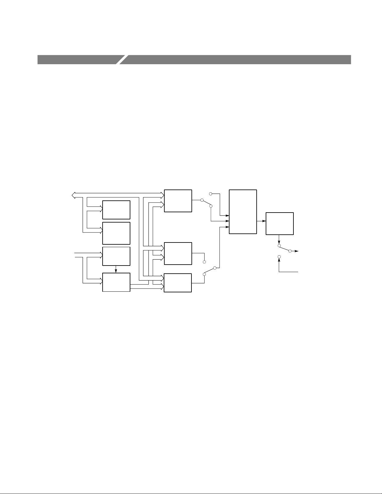
See Figure 1--1 for a diagram of the module’s internal structure.
CPU Bus
Clock/Frame
Reset Bus
Module
NVRAM
Module
Flash
Memory
Module
Delay
Module
Clocks
Video
Pattern
Memory
Zone
Plate
Generator
Burst
Generator
Figure 1- 1: Simplified block diagram of the AWVG1 Generator module
The module is a single-channel generator, which outputs either the internally
generated signal or an analog video signal from the rear-panel input on its three
output connectors. The rear-panel input is provided for convenience of operation
so that the output signal can be switched between the internally generated signal
and the external signal, which can come from another source, such as the AVG1
Generator module. There is no loop-through of the external signal when the
module output is disabled or when the power is off.
Amplitude
Control
Mux
Video
Amplitude
Sine wave
DAC
and
Filter
Wideband
Analog Video
(three outputs)
Analog
Video Input
For internally generated signals, output signal data is obtained from either the
signal memory or the zone plate generator. The basic signal contains luminance
information only, so burst is generated and multiplexed in at the appropriate
time.
The module’s memory architecture is run-length encoded. This allows signals
that have redundancy to occupy a smaller space, or conversely more complex
AWVG1 Wideband Video Generator User Manual
1- 1
Page 20

Getting Started
Accessories
signals in the same space. For signals with no redundancy, there is enough
memory for 30 unique lines of signal data.
This module provides the following signal types: line and field sweeps with
frequency markers (fixed and variable), zone plates, multipulses, multibursts,
and pulse and bars. Front panel control of sweep marker frequency and sweep
start and stop frequencies is provided.
Table lists standard and optional accessories for the module. Standard accessories
are included with the module, and optional accessories are available for purchase
to use with the module.
Table 1- 1: Standard and Optional Accessories
Accessory Typo of Accessory Part Number
AWVG1 Wideband Video Generator User Manual Standard 070-9051-XX
Configuration
T-10 Torx Tip Standard 003-1604-XX
Screws (2 ea.) Standard 211-0725-XX
Blank rear panel Standard 333-4113-XX
AWVG1 Wideband Video Generator Service Manual Optional 070-9302-XX
This module does not require any configuration.
1- 2
AWVG1 Wideband Video Generator User Manual
Page 21

Functional Check
Getting Started
Perform the following procedure to determine if the module is operating
correctly. For this procedure, you will need a television monitor to view the
generator signals.
1. If the module is not installed in the TG 2000 mainframe, use the installation
procedures in Appendix D: Hardware Installation.
2. Cycle instrument power. The mainframe runs a self test on all modules.
To determine if the self test was successful, push the Module button and see
if the AWVG1 module icon appears. If you have more than one AWVG1
Generator module installed, check the slot number on the display to be sure
the module you are checking appears.
3. If necessary, install signal sets into the module using the procedure on
page D--6. Be sure that you have the Bullseye signal installed.
4. Connect your monitor to the Output 1 BNC connector on the AWVG1
Generator module rear panel, and terminate the monitor’s loop-through
connector in 75 Ω.
5. Terminate the AWVG1 Generator module outputs 2 and 3 in 75 Ω. (This is
necessary for the module self cal.)
6. Wait 20 minutes for the instrument to warm up.
7. Push the Utilities button, and then do the following:
a. Touch Module Self Cal on the display.
b. Touch the self-cal icon for the module you are testing.
c. Touch Start Cal on the display.
The Self Cal takes 2 to 5 minutes, depending on the module. An error
message indicates a failed calibration. If the Self Cal fails, contact your
Tektronix representative for assistance.
8. Push the Modules front-panel button and touch AW VG 1 on the display.
9. Select a signal set that is compatible with your monitor, and then touch the
Zoneplate icon to select the Bullseye signal as the output signal. Selecting
the signal automatically ensures that the module output is enabled.
10. Adjust your monitor to view the signal. Check that a circle signal appears,
similar to the signal shown in Figure 1--2.
AWVG1 Wideband Video Generator User Manual
1- 3
Page 22

Getting Started
Figure 1- 2: Bullseye signal as displayed on a television monitor
11. Move the output cable to each of the BNC output connectors to ensure that
the signal appears correctly.
12. Move the output cable back to Output 1.
13. Select a different zone plate test signal and check that the displayed signal
changes. You only need to do this on Output 1.
14. Check the AWVG1 External Input as follows:
a. Using a 75 Ω coaxial cable, connect a television test signal from a
source such as an AVG1 module, to the AWVG1 module External Input.
b. Check the output of the AWVG1 module on the television monitor in
pulse cross mode. Check that the signal is displayed correctly . Check
that the appropriate burst for your video format is present in the signal.
This concludes the functional check.
1- 4
AWVG1 Wideband Video Generator User Manual
Page 23

Operating Basics
Page 24

Page 25
Functional Overview
This section provides an overview of the AWVG1 Generator module. If you are
not familiar with the operation of the TG 2000 Signal Generation Platform, refer
to the TG 2000 Signal Generation Platform User Manual before reading this
section.
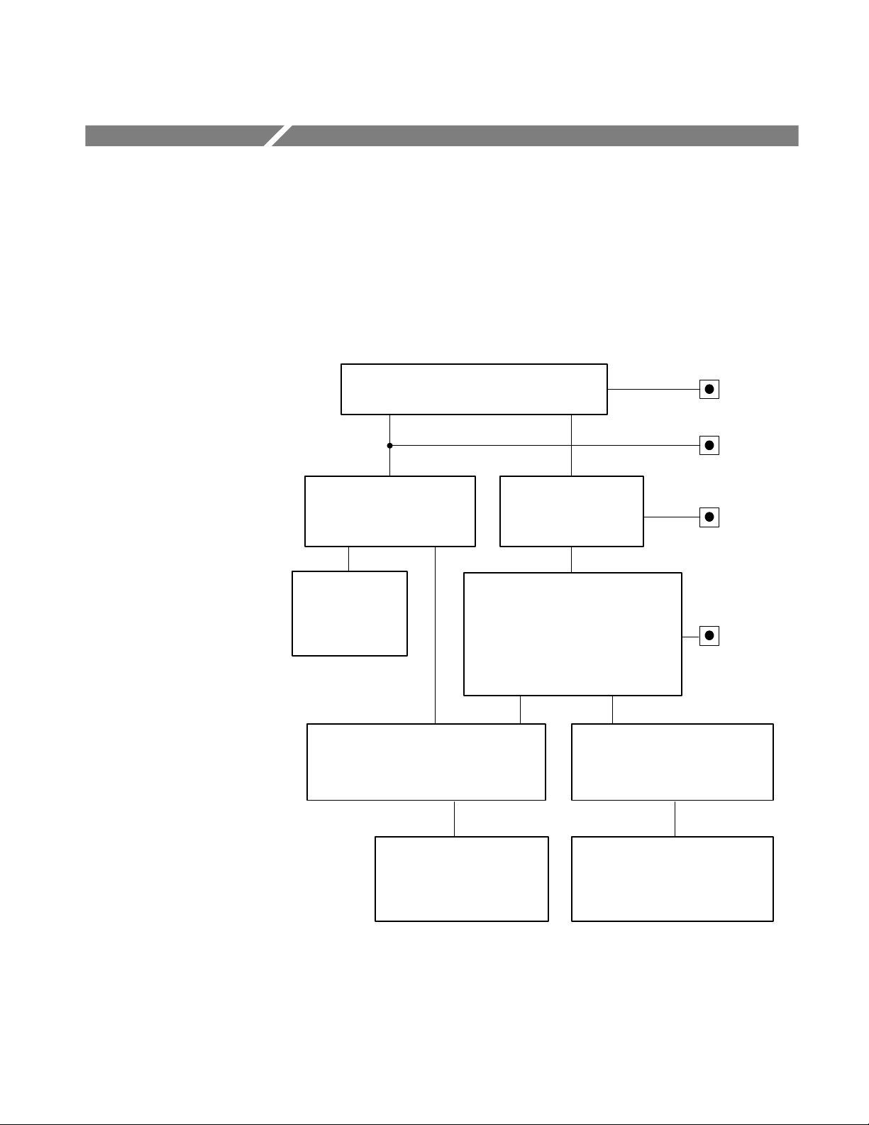
Figure 2--1 shows the module’s menu structure.
Edit Module window
Touch Rename
Module
Rename Module
window
Enter new name for
module
Module Parameters window
Touch Output
Enable/Disable
Modules window
Touch Module
Parameters
output signal or touch EXT INPUT to use the
externally applied signal as the output signal
Touch Module Timing
Touch AWVG1 module
Signal Sets window
Touch desired signal set
(usually represents format)
Test Signals window
Touch desired Test Signal icon to select
Touch Module
Parameters
Touch Active
Signal Parameters
Active Signal Parameters window
Touch Video, Zoneplate, or
Signal Information
Push Modules
button
Push Edit
button
Push Signal
Sets button
Push Test
Signals button
Figure 2- 1: Basic menu structure for the module
AWVG1 Wideband Video Generator User Manual
Module Timing window
Set module timing with
respect to the BG1 module
Video, Zoneplate, or Signal
Information windows
Set video or zoneplate parameters,
or view details of selected signal
2- 1
Page 26

Functional Overview
Outputs
Input
Online Help
The three BNC output connectors for this module all supply the same output
signal. For information on how to select the output signal, refer to Select the
Output Signal on page 2--5.
The BNC input connector is compensated for 75 Ω. This input is provided so
that you can use the output of another module (such as the AVG1 Generator
module) as the output signal for the AWVG1 Generator module. To do this, you
must select External Input as the AWVG1 Generator module output signal. For
information on how to do this, refer to Select the Output Signal on page 2--5.
Push the front-panel HELP button to display a help window. The help window
describes the AWVG1 Generator module window you were using when you
pushed HELP.
If a help window is longer than the display, you can scroll through the help text
using the Navigation arrow keys. To exit the help window, touch Quit.
2- 2
AWVG1 Wideband Video Generator User Manual
Page 27

Operating Procedures
This section is organized into the following main topics:
H Power on the mainframe and select the module
H Select the output signal
H Active signal parameters
H Module parameters
Refer to Figure 2--1 on page 2--1 for information on how to access the appropriate windows for these procedures.
Equipment Hookup
No special test equipment is necessary for these procedures, but it will be helpful
to view the signals on a monitor. To do this, connect the module’s signal output
to a television monitor, using a 75
Ω cable and a 75 Ω termination.
AWVG1 Wideband Video Generator User Manual
2- 3
Page 28
Operating Procedures
Power On and Select the Module
After the module is installed in the mainframe, and the mainframe is installed in
the rack or other location where it will be used, power on the mainframe and
select the module by following these steps:
1. Set the rear-panel power switch to the ON position.
2. Press the front-panel POWER switch if necessary.
3. Wait for a few seconds as the mainframe executes confidence tests on the
mainframe and modules. Check for any error messages that might appear.
4. When self tests are complete, the instrument displays icons representing the
generator modules. If an installed module is not represented, refer to
Troubleshooting in the AWVG1 Wideband Video Generator Service Manual.
NOTE. When the platform is shipped from the factory, the module is named
AWVG1:X where X represents the slot number in which the module is installed.
However, you can edit the module name by selecting the module and then
pushing the Edit button. The TG 2000 Signal Generation Platform User Manual
provides more information.
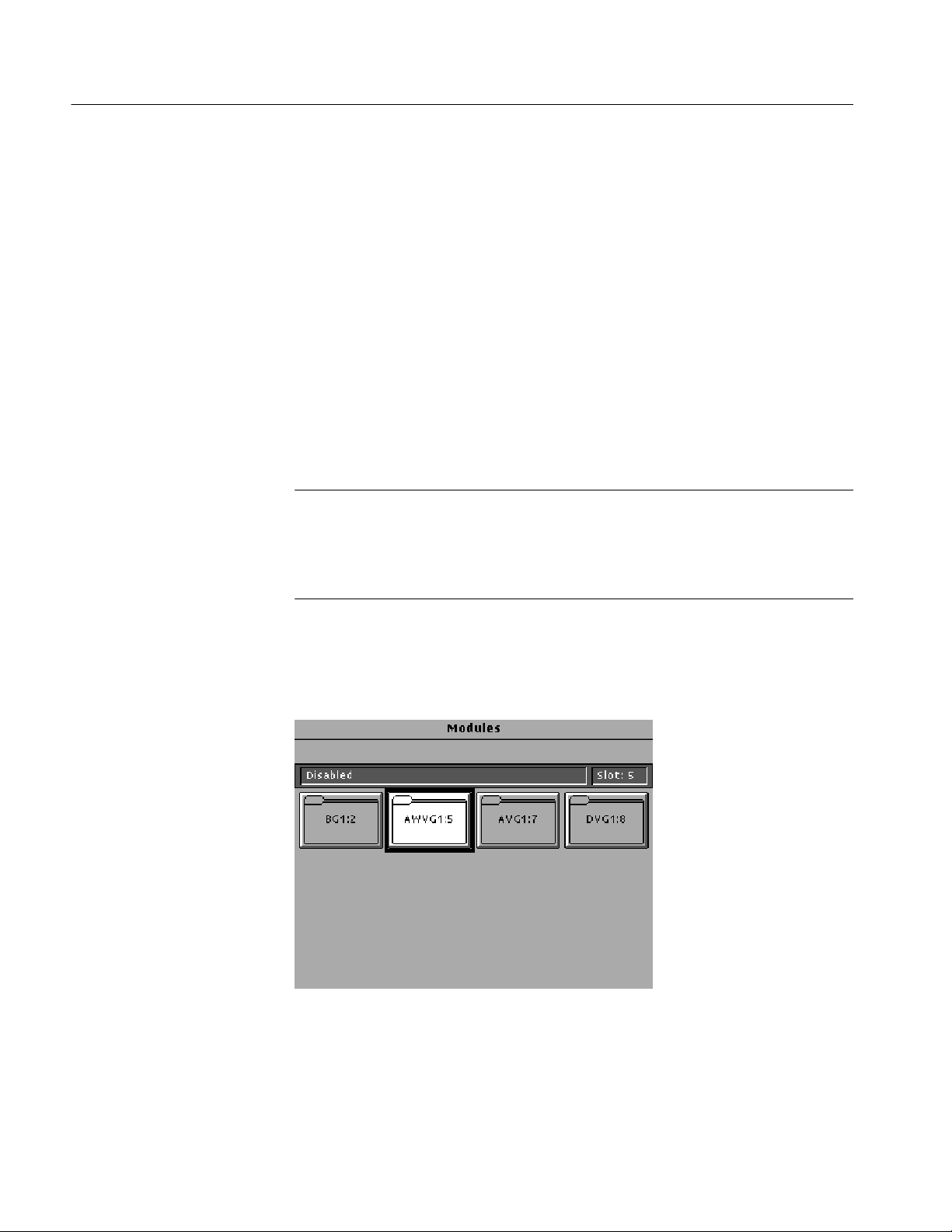
5. Since you have just powered on the mainframe, the Modules window (shown
below) is displayed. To select the module at other times, push the front-panel
Modules button to access this window.
a. Touch the module icon on the display (or push the Signal Sets button if
the desired icon is already highlighted). The installed signal sets for the
module appear. Selections you make after this will pertain to the
AWVG1 Generator module.
2- 4
AWVG1 Wideband Video Generator User Manual
Page 29
Select the Output Signal
You can select any of the AWVG1 Generator module signals that are loaded in
your instrument to be the output signal, supplied on the three rear-panel outputs.
To select the output signal, follow these steps:
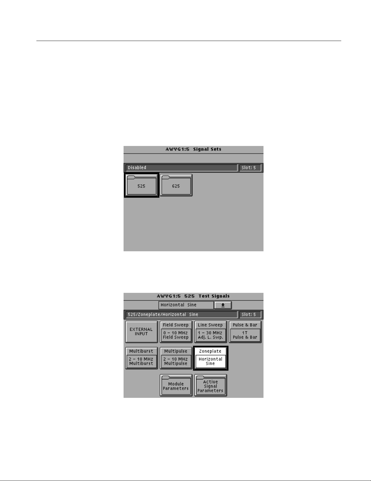
1. Push the Signal Sets button to open the window shown below. Check that
Operating Procedures
there is an icon for each installed signal set. If your signal sets are not
installed, refer to Signal Set Installation on page D -- 6.
2. Touch the desired signal set on the display. The Test Signals window for the
selected signal set appears. In the following example, 525 is selected.
3. Each test signal icon in the Test Signals window represents one or more
signals that the module can generate. In this example, the Zoneplate test
signal icon is selected, and the Horizontal Sine signal is being generated.
AWVG1 Wideband Video Generator User Manual
2- 5
Page 30
Operating Procedures
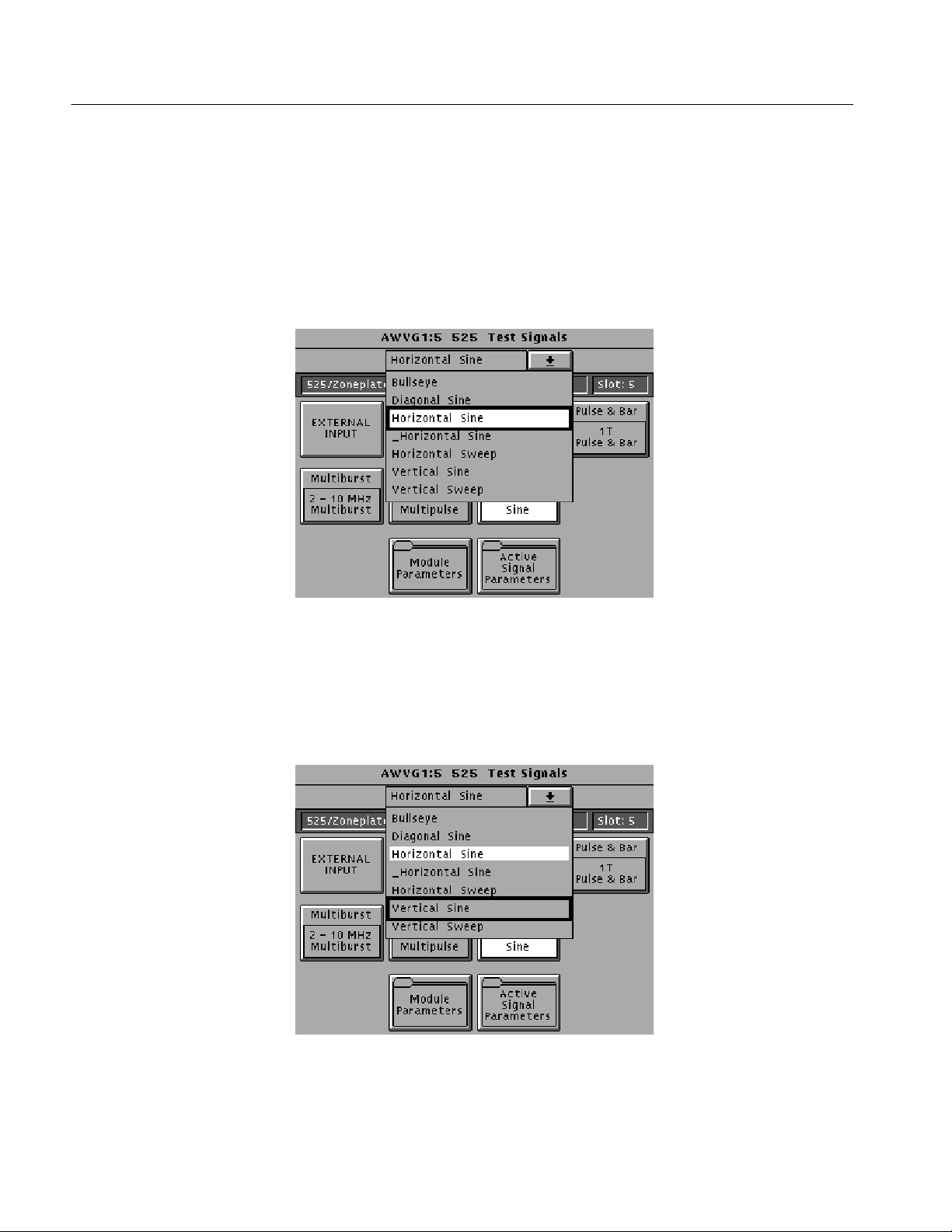
4. To change to another zone plate signal, use one of the following methods:
a. Touch the Zone Plate repeatedly to browse through all available signals.
b. Touch the combo box below the window title (or rotate the Navigation
knob) to display a list of all the signals for the selected icon, as shown in
the following example. (_Horizontal Sine is a user-generated signal.)
c. To select a signal from the list, rotate the Navigation knob to move the
cursor to that signal, and then press the front panel Select key. In the
following example, the selected output signal is Horizontal Sine, but the
cursor has been moved to Vertical Sine. Pressing the Select key will
select Vertical Sine as the output signal.
5. To change to a different signal type, such as Multiburst, touch the corresponding icon on the display. Then select the signal as shown in step 4.
2- 6
AWVG1 Wideband Video Generator User Manual
Page 31

Operating Procedures
6. To select the output signal using the List window, display the list of test
signals by pushing the front-panel List button. Use the Navigation arrow
keys to highlight the module and signal, and then push the Select button.
7. If you want to use the signal on the rear-panel input as the output signal,
touch the EXTERNAL INPUT icon to highlight it. For example, you can
connect a coaxial cable from the output of the AVG1 Generator module to
the input of the AWVG1 Generator module, and then select EXTERNAL
INPUT. This will supply the AVG1 Generator module signal as the output on
the AWVG1 Generator module.
AWVG1 Wideband Video Generator User Manual
2- 7
Page 32

Operating Procedures
Active Signal Parameters
The following procedures discuss windows that are accessed through the Active
Signal Parameters window, shown below. Changes that you make to parameters
in any of these windows affect only the active signal.
To enter the Active Signal Parameters window for the AWVG1 Generator
module, follow these steps:
1. Select the module if not already selected.
2. Push the Test Signals button.
3. Touch Active Signal Parameters at the bottom of the screen. The Active
Signal Parameters window appears, as shown below.
2- 8
AWVG1 Wideband Video Generator User Manual
Page 33

Operating Procedures
Signal Information
You can view detailed information about the selected signal.
1. In the Active Signal Parameters window, shown on page 2--8, touch S ignal
Information.
2. View the signal information, as shown in the following illustration.
AWVG1 Wideband Video Generator User Manual
2- 9
Page 34

Operating Procedures
Video Parameters
By making and saving changes to the video parameters, you can create a new
signal that is based on the selected signal. Changes you make affect only the new
signal. To change the video parameters settings, perform the following steps:
1. Push the Test Signals button. In the Test Signals window, select the
1 -- 30 MHz Adjustable Line Sweep signal. This signal has five frequency
markers that you can adjust.
2. Touch Active Signal Parameters at the bottom of the window. The Active
Signal Parameters window appears, as shown on page 2--8. Touch the
Video icon.
3. The Video Parameters window appears. Select the parameter you want to
change using the Navigation cursor keys. The example below shows
Marker 3 selected.
2- 10
AWVG1 Wideband Video Generator User Manual
Page 35

Operating Procedures
NOTE. Changes to certain parameters cause changes to other parameters. To
return all values to their state when the Video Parameters window was opened,
touch Reset on the display.
4. Enter a value using the Navigation knob or keypad. This will adjust the
selected parameter for the currently selected test signal.
5. Sync Amplitude and Burst Amplitude must be set to 0% or 100%.
6. For horizontal sweep and field sweep signals, set the sweep parameters
(Sweep Amplitude, Sweep Start Freq and Sweep Stop Freq).
7. Horizontal sweep signals can have adjustable markers. To change marker
settings, use the Navigation cursor keys (up/down arrows) to move to the
desired marker and press the Select key to select the marker. Use the knob or
keypad to set the frequency. Touch the Marker X icon (X represents the
number of the currently selected marker) to enable or disable the marker.
NOTE. When two or more markers overlap, only one marker will appear on the
waveform; the others will be blanked.
8. Field sweep signals do not support adjustable markers. However, some field
sweep signals have fixed markers. You can alter the marker frequencies by
changing the sweep start and stop frequency. This is because the markers are
at 1/6, 2/6, 3/6, 4/6, and 5/6 of the total sweep. For example, start with a
field sweep signal that has a 0 to 30 MHz sweep and markers at 5, 10, 15,
20, and 25 MHz. If you change the sweep stop to 6 MHz, the markers will
be at 1, 2, 3, 4, and 5 MHz.
9. When all desired parameters are set, touch Quit/Save. If you made changes,
a popup menu asks you to select Save As or Quit.
10. Touch Save As. A text entry window appears, showing the current signal
name preceded by an underscore. (All user-defined signals are preceded by
an underscore, and you cannot delete it.)
AWVG1 Wideband Video Generator User Manual
2- 11
Page 36

Operating Procedures
11. To save the signal under the displayed name, touch OK. To rename the
signal, delete the displayed name using the backspace key (BS).
12. Enter the new name. Touch Set 1 or Set 2 to display additional sets of
characters. Touch Shift to display a lower case or upper case alphabet. In the
following example, Set 1 was used to enter an exclamation mark.
2- 12
13. When you have entered the desired text, touch OK. Now you have a new
signal defined by the parameters you set.
AWVG1 Wideband Video Generator User Manual
Page 37

Operating Procedures
Zone Plate Test Signal
By making and saving changes to the zone plate parameters, you can create a
new signal that is based on the selected signal. Changes you make affect only the
new signal. For more information on Zone Plate Signals, refer to Appendix C.
NOTE. You can also define zone plate signals using the SDP2000 Signal
Development Program (Version 2.0 and up). Refer to the SDP2000 online help.
To change the zone plate coefficients, perform the following steps:
1. Push the Test Signals button. In the Test Signals window, touch the Zone
Plate icon to select the zone plate signal you want to modify. (This procedure
uses the 625 Bullseye signal.)
2. Touch the Active Signal Parameters icon at the bottom of the window. The
Active Signal Parameters window appears, as shown on page 2--8.
AWVG1 Wideband Video Generator User Manual
2- 13
Page 38

Operating Procedures
3. Touch the Zone Plate icon. The Zone Plate Parameters window appears, as
shown below.
Because you selected a standard zone plate signal, a Pattern Control
Parameter appears at the top of the list of parameters (Circle Frequency in
this case). This parameter controls the basic pattern frequency by adjusting a
set of dependent parameters, which are indented on the display. In this
example, the Circle Frequency parameter has been selected by pressing the
front-panel Select key.
4. Change parameters and save a new signal as follows:
a. To see how the module informs you of a change to the Pattern Control
Parameter, press the Navigation arrow to move the cursor down to KX
(H freq). Rotate the Navigation knob. A popup menu will warn you that
the Pattern Control Parameter will become invalid. This means that the
signal will change shape. Touch OK to continue.
b. With the KX parameter still selected, press the 9 key on the keypad,
followedbytheEnter key to change the parameter value to 9 c/aph.
c. If you touch T Reset, it will enable or disable the temporal movement of
the zone plate signal you create.
d. Touch Quit/Save. A dialog box will be displayed; touch Save As to
name the new signal you have created. You will be using the same screen
that was used on page 2--12. This will not modify the original Bullseye
signal, but will create a new signal based on the Bullseye signal.
2- 14
e. After you name the new signal, you can see the new name displayed in
the status bar. Note that there is no Pattern Control Parameter, and that
there are no dependant (indented) parameters.
AWVG1 Wideband Video Generator User Manual
Page 39

Operating Procedures
f. Go to the Test Signals window and select the Bullseye signal again. Go
back to the zone plate Parameters window, and note that the Circle
Frequency reappears, with the five dependent parameters.
g. Go back to the Test Signals window and select a different zone plate
signal, such as H Sine. Now go to the zone plate Parameters window and
note the dependent parameters for that signal.
AWVG1 Wideband Video Generator User Manual
2- 15
Page 40

Operating Procedures
Module Parameters
The following procedures discuss windows that are accessed through the Module
Parameters window, shown below. Changes that you make to parameters in any
of these windows affect the entire module.
To enter the Module Parameters window for the AWVG1 Generator module,
follow these steps:
1. Select the module, if not already selected.
2. Push the Test Signals button.
3. Touch Module Parameters at the bottom of the screen. The Module
Parameters window appears, as shown below.
2- 16
4. Another way to access this window is as follows:
a. Push the Modules button.
b. Ensure that the module is highlighted.
c. Push the Edit button.
d. Touch Module Parameters.
AWVG1 Wideband Video Generator User Manual
Page 41

Operating Procedures
Enable/Disable the
Output Signal
Timing
If you disable the module output, it releases all system resources used by this
module. To disable the module output, follow these steps:
1. Select the module, if not already selected.
2. Push the Test Signals button.
3. Touch Module Parameters at the bottom of the screen. The Module
Parameters window (shown on page 2--16) appears.
4. Touch the Output icon to toggle the state of the module’s output signal.
5. Touch Quit to exit.
You can set the horizontal and vertical timing of the AWVG1 Generator module
with respect to the BG1 Generator module, using the Module Parameters
window. Changes you make to timing affect all signals for the AWVG1
Generator module. To set the timing, perform the following steps:
1. In the Module Parameters window, shown on page 2--16, touch the module
timing icon. The Timing window appears.
2. Set the horizontal timing of this module with respect to the BG1 Generator
module as follows:
a. Touch H Feel to select Coarse. (A front-panel knob increment is now
equal to a full cycle of the sample clock, typically 72 MHz.) Rotate the
navigation knob to select the approximate value; rotate counter-clockwise to advance the timing, or clockwise to delay the timing.
b. Touch H Feel to select Fine. (Knob increments are now subclock
cycles.) Rotate the knob to select the final value.
AWVG1 Wideband Video Generator User Manual
2- 17
Page 42

Operating Procedures
c. To enter a specific value, use the keypad and then press the Select key.
(The default is 0.000 sec.)
3. Set the vertical timing of this module with respect to the BG1 Generator
module by performing the following steps. (The default is 0 lines.)
a. Touch V ertical on the display.
b. Rotate the Navigation knob counter-clockwise to advance the timing or
clockwise to delay the timing.
c. To enter a specific value, use the keypad and then press the Select key.
NOTE. When you enter more than 1 line of horizontal advance or delay, the
vertical timing is advanced or delayed.
4. If you want to set horizontal and vertical values to zero, touch Reset All.
5. When you have made all desired changes, touch Quit to exit the Timing
window.
6. Touch Quit to exit the Module Parameters window. All changes are saved.
2- 18
AWVG1 Wideband Video Generator User Manual
Page 43

Syntax and Commands
Page 44

Page 45

Syntax
Programming Model
This section contains information on the Standard Commands for Programmable
Instruments (SCPI) and the programming structure you can use to program your
AWVG1 Wideband Video Generator module.
Specific conditions must exist before programming commands will affect the test
signal generated by a module.
Addressing Module Test
Signals
Command Arguments
The following two steps must be performed before the test module will respond
to signal parameter commands.
1. Select the module to be addressed before executing any commands. Many of
the commands used by the TG 2000 Signal Generation Platform are shared
by several modules and will be accepted without a reported error.
2. Enable the module using the :OUTPut:STATe ON command. The output
state of the module must be enabled before test signal parameters can be
changed.
Many commands will accept either string or numeric arguments. For example: a
Boolean argument can either be “1” or “ON”.
Signal parameter commands that have a :STEP node can accept either a numeric
value or they can accept a string argument that refers to the :STEP increment.
Signal parameter commands with a :STEP node will accept the following strings
in addition to a numeric value:
UP. Use this argument to increase the parameter value one increment as defined
by the :STEP value.
DOWN. Use this argument to decrease the parameter value one increment as
defined by the :STEP value.
AWVG1 Wideband Video Generator User Manual
3- 1
Page 46

Syntax
MINimum. Use this argument to set the parameter value to the minimum
acceptable value.
MAXimum. Use this argument to set the parameter value to the maximum
acceptable value.
DEFault. Use this argument to set the parameter value to the default value.
Argument Example
The following example demonstrates the effect of each of the arguments when
used with a step value.
1. :INSTrument:SELect ”AWVG1:#” selects the AWVG1 Generator
module located in the slot number indicated by the “#” symbol.
2. :OUTPut:STATe ON enables the module and displays the loaded test
signal.
3. :SOURce:ZONE:KX --5.98 sets the zone plate K
parameter (horizontal
X
frequency) to --5.98 cycles per active picture height (c/aph).
2
4. :SOURce:ZONE:KX2 8.5 sets the zone plate K
sweep) to 8.5 cycles per active picture height squared (c/aph
5. :SOURce:ZONE:KXY 0 sets the zone plate K
parameter (horizontal
X
parameter (vertical
XY
2
).
change in horizontal frequency) to 0.00 cycles per active picture height
squared (c/aph
6. :SOURce:ZONE:KY --4.50 sets the zone plate K
2
).
parameter (vertical
Y
frequency) to --4.50 cycles per active picture height (c/aph).
7. :SOURce:ZONE:KY2 8.99 sets the zone plate K
sweep) to 8.99 cycles per active picture height squared (c/aph
2
parameter (vertical
Y
2
).
3- 2
8. :SOUR:MVID:MARK1 1000.0 sets the first frequency
marker to 1 MHz.
9. :SOUR:MVID:MARK2 2000.0 sets the second frequency
marker to 2 MHz.
10. :SOUR:MVID:MARK5 5000.0 sets the fifth frequency
marker to 5 MHz.
AWVG1 Wideband Video Generator User Manual
Page 47

SCPI Commands and Queries
SCPI is a standard created by a consortium that provides guidelines for remote
programming of instruments. These guidelines provide a consistent programming environment for instrument control and data transfer. This environment
uses defined programming messages, instrument responses, and data format
across all SCPI instruments, regardless of manufacturer. The TG 2000 Signal
Generation Platform uses a command language based on the SCPI standard.
The SCPI language is based on a hierarchical or tree structure (see Figure 3--1)
that represents a subsystem. The top level of the tree is the root node; it is
followed by one or more lower-level nodes.
Syntax
OUTPut
CIRCle
DIAMeter
POSitionSTATe
Root node
Lower-level
nodes
Figure 3- 1: Example of SCPI subsystem hierarchy
You can create commands and queries from these subsystem hierarchy trees.
Commands specify actions for the instrument to perform. Queries return
measurement data and information about parameter settings.
For more information about SCPI commands, programming structure, and
TG 2000 Signal Generation Platform status and events, refer to the TG 2000
Signal Generation Platform User Manual.
AWVG1 Wideband Video Generator User Manual
3- 3
Page 48

Syntax
3- 4
AWVG1 Wideband Video Generator User Manual
Page 49

Functional Command Groups
This section describes the module’s commands in the following groups:
H MMEMory (see TG 2000 Signal Generation Platform User Manual)
H OUTPut
H SENSe
H SOURce
Entries followed by questions marks are queries; those without question marks
are commands. Entries followed by a question mark in parentheses (?) can be
both a command and a query.
MMemory
Two MMEMory commands are listed here for your reference. You can use these
to set and query the output test signal for the module. Detailed information for
using these commands (as well as other commands that can be used with the
entire platform) are located in the TG 2000 Signal Generation Platform User
Manual.
Table 3- 1: :MMEMory commands
Command Description
:MMEMory:LOAD:SIGNal Load a signal into a modul e and identify that signal as the active
signal (output signal) for that module
:MMEMory:SIGNal:ACTive? List the active signal (output signal) for a module
Output
Use these commands to select the output characteristics of the module.
Table 3- 2: :OUTPut commands
Command Description
:OUTPut:STATe(?) Set or query module output (enabled or disabled)
:OUTPut:SOURce(?) Set or query the source of the AWVG1 output signal (internal or
external)
AWVG1 Wideband Video Generator User Manual
3- 5
Page 50

Functional Command Groups
Sense
Use these commands to adjust the module timing.
Table 3- 3: :SENSe commands
Command Description
:SENSe:CORRection:MDELay:HORizontal(?) Set or query horizontal time delay of the module with respect to
the rest of the instrument
:SENSe:CORRection:MDELay:VERTical(?) Set or query vertical time delay of the module with respect to the
rest of the instrument
Source
Use these commands to define the signal parameters for the module.
Table 3- 4: :SOURce commands
Command Description
:SOURce:MVIDeo:SYNC(?) Set or query the amplitude of the sync pulse
:SOURce:MVIDeo:BURST(?) Set or query the color burst amplitude
:SOURce:SWEep:AMPLitude(?) Set or query the sweep signal amplitude
:SOURce:SWEep:FREQuency:STARt(?) Set or query the frequency of the sweep start
:SOURce:SWEep:Frequency:STOP(?) Set or query the frequency of the sweep end point
:SOURce:SWEep:MARKer5:FREQuency(?) Set or query the frequency of frequency markers 1 through 5
:SOURce:SWEep:MARKer5:STATe(?) Set or query the state of frequency markers 1 through 5
:SOURce:ZONE:FREQuency(?) Set or query the value of the zone plate frequency
:SOURce:ZONE:AMPLitude(?) Set or query the value of the zone plate amplitude
:SOURce:ZONE:K(?) Set or query the value of the K parameter
:SOURce:ZONE:KX(?) Set or query the value of the KX parameter
:SOURce:ZONE:KX2(?) Set or query the value of the KX2 parameter
:SOURce:ZONE:KXT(?) Set or query the value of the KXT parameter
:SOURce:ZONE:KXY(?) Set or query the value of the KXY parameter
:SOURce:ZONE:KY(?) Set or query the value of the KY parameter
:SOURce:ZONE:KY2(?) Set or query the value of the KY2 parameter
:SOURce:ZONE:KYT(?) Set or query the value of the KYT parameter
:SOURce:ZONE:KT(?) Set or query the value of the KT parameter
:SOURce:ZONE:KT2(?) Set or query the value of the KT2 parameter
:SOURce:ZONE:TRESet:STATe(?) Set or query the state of the T parameter
3- 6
AWVG1 Wideband Video Generator User Manual
Page 51

OUTPut Subsystem
The OUTPut subsystem enables the actual output of the AWVG1 Generator
module. The OUTPut subsystem commands may release resources controlled by
the signal manager or the clock manager.
NOTE. The module must be selected with the INSTrument subsystem prior to
using these commands. For more information, refer to page 3--2.
A detailed description of the AWVG OUTPut commands follows the Command
Tree.
Command Tree
:OUTPut
:STATe <Boolean>
:SOURce EXTernal | INTernal
AWVG1 Wideband Video Generator User Manual
3- 7
Page 52

OUTPut Subsystem
:OUTPut:STATe(?)
Use this command to set or query the state of the AWVG1 Generator module.
Syntax
Parameters
Default Value
Errors and Events
Dependencies
Examples
Related Commands
:OUTPut:STATe <Boolean>
:OUTPut:STATe?
Command Query response
<Boolean> = ON or 1, OFF or 0 1, 0
ON
None
None
Command: :OUTP:STAT ON
Query: :OUTP:STAT?
Response: ON
None
3- 8
AWVG1 Wideband Video Generator User Manual
Page 53

:OUTPut:SOURce(?)
OUTPut Subsystem
Use this command to set or query the source (internal or external) of the
AWVG1 Generator module output signal.
Syntax
Parameters
Default Value
Errors and Events
Dependencies
Examples
:OUTPut:SOURce<char>
:OUTPut:SOURce?
Command Query Response
<char> = EXTernal
INTernal
None
None
None
Command: :OUTP:SOUR INT
Query: :OUTP:SOUR?
Response: INT
EXT
INT
Related Commands
AWVG1 Wideband Video Generator User Manual
OUTPut:STATe, :MMEM:LOAD:SIGNal.
The :MMEM:LOAD:SIGNal command loads a signal to the module (output
signal) and sets the OUTPut:SOURce to internal. See the TG 2000 Signal
Generation Platform User Manual for detailed information about the :MMEM
commands.
3- 9
Page 54

OUTPut Subsystem
3- 10
AWVG1 Wideband Video Generator User Manual
Page 55

SENSe Subsystem
The SENSe subsystem commands adjust the timing of the module in relation to
the rest of the TG 2000 Signal Generation Platform by correcting the module
delay. The BG1 Generator module is the reference.
A detailed description of the AWVG SENSe commands follows the Command
Tree.
Command Tree
:SENSe
:CORRection
:MDELay
:VERTical <numeric_value>
:HORizontal <numeric_value>
AWVG1 Wideband Video Generator User Manual
3- 11
Page 56

SENSe Subsystem
:SENSe:CORRection:MDELay:VERTical(?)
Use this command to set or query the vertical time delay of the module.
The query returns an integer value even if the command used a floating point
value. Fractional parts are ignored.
Settings will be retained through power cycle.
Syntax
Parameters
Default Value
Errors and Events
Dependencies
Examples
Related Commands
:SENSe:CORRection:MDELay:VERTical <numeric_value>
:SENSe:CORRection:MDELay:VERTical?
Command Query response
<numeric_value> = <NRf>
1
None
None
Command: :SENS:CORR:MDEL:VERT 12
Query: :SENS:CORR:MDEL:VERT?
Response: 12
:SENSe:CORRection:MDELay:HORizontal
<NR1>
3- 12
AWVG1 Wideband Video Generator User Manual
Page 57

:SENSe:CORRection:MDELay:HORizontal(?)
Use this command to set or query the horizontal timing delay of the module with
respect to the rest of the instrument.
Argument units are in microseconds. Arguments that exceed the horizontal time
value adjust the vertical delay to accommodate the requested delay.
Settings will be retained through the power cycle.
SENSe Subsystem
Syntax
Parameters
Default Value
Errors and Events
Dependencies
Examples
Related Commands
:SENSe:CORRection:MDELay:HORizontal <numeric_value>
:SENSe:CORRection:MDELay:HORizontal?
Command Query response
<numeric_value> = <NRf>
0.00
None
None
Command: :SENS:CORR:MDEL:HOR 23.0
Query: :SENS:CORR:MDEL:HOR?
Response: 23.0
:SENSe:CORRection:MDELay:VERTical
<NR2>
AWVG1 Wideband Video Generator User Manual
3- 13
Page 58

SENSe Subsystem
3- 14
AWVG1 Wideband Video Generator User Manual
Page 59

SOURce Subsystem
The SOURce subsystem commands control the AWVG1 Generator module
signal source. They can enable the sync and burst, as well as adjust the sweep
and zone plate parameters. When a K factor command contains a 2, it signifies a
squared parameter. For example, KX2 signifies KXX.
A description of the AWVG1 Generator module SOURce commands follows the
Command Tree.
Command Tree
:SOURce
:MVIDeo
:SWEep
:ZONE
:SYNC <numeric_value>
:BURSt <numeric_value>
:AMPLitude <numeric_value>
:FREQuency:STARt <numeric_value>
:FREQuency:STOP <numeric_value>
:MARKer5:FREQuency <numeric_value>
:MARKer5:STATe <Boolean>
:FREQuency <numeric_value>
:AMPLitude <numeric_value>
:K <numeric_value>
:KX <numeric_value>
:KX2 <numeric_value>
:KXT <numeric_value>
:KXY <numeric_value>
:KY <numeric_value>
:KY2 <numeric_value>
:KYT <numeric_value>
:KT <numeric_value>
:KT2 <numeric_value>
:TRESet:STATe <Boolean>
AWVG1 Wideband Video Generator User Manual
3- 15
Page 60

SOURce Subsystem
:SOURce:MVIDeo:SYNC(?)
Use this command to set or query the amplitude of the sync pulse. Units are
percent.
Sync amplitude has only two values: 0.00 and 100.0 percent. Arguments greater
than 0.00 will be adjusted to 100.0. Units are percent.
Syntax
Parameters
Default Value
Errors and Events
Dependencies
Examples
Related Commands
:SOURce:MVIDeo:SYNC <numeric_value>
:SOURce:MVIDeo:SYNC?
Command Query response
<numeric_value> = <NRf> <NR2>
100.0
None
None
Command: :SOUR:MVID:SYNC 0
Query: :SOUR:MVID:SYNC?
Response: 0.0
None
3- 16
AWVG1 Wideband Video Generator User Manual
Page 61

:SOURce:MVIDeo:BURSt(?)
Use this command to set or query the amplitude of the burst pulse. Units are
percent.
Burst level has only two values: 0.00 and 100.0 percent. Arguments greater than
0.00 will be adjusted to 100.0.
SOURce Subsystem
Syntax
Parameters
Default Value
Errors and Events
Dependencies
Examples
Related Commands
:SOURce:MVIDeo:BURSt <numeric_value>
:SOURce:MVIDeo:BURSt?
Command Query response
<numeric_value> = <NRf> <NR2>
100.0
None
None
Command: :SOUR:MVID:BURS 0
Query: :SOUR:MVID:BURS?
Response: 0.0
None
AWVG1 Wideband Video Generator User Manual
3- 17
Page 62

SOURce Subsystem
:SOURce:MVIDeo:SWEep:AMPLitude(?)
Use this command to set or query the amplitude of the sweep signal. Units are
millivolts.
Syntax
Parameters
Default Value
Errors and Events
Dependencies
Examples
Related Commands
:SOURce:MVIDeo:SWEep:AMPLitude <numeric_value>
:SOURce:MVIDeo:SWEep:AMPLitude?
Command Query response
<numeric_value> = <NRf> <NR2>
714.3
None
The default value is based on the source file of the active signal.
Command: :SOUR:SWE:MVID:AMPL 90
Query: :SOUR:SWE:MVID:AMPL?
Response: 90.0000
None
3- 18
AWVG1 Wideband Video Generator User Manual
Page 63

:SOURce:SWEep:FREQuency:STARt(?)
Use this command to set or query the frequency of the sweep start point. Units
are megahertz.
SOURce Subsystem
Syntax
Parameters
Default Value
Errors and Events
Dependencies
Examples
Related Commands
:SOURce:SWEep:FREQuency:STARt <numeric_value>
:SOURce:SWEep:FREQuency:STARt?
Command Query response
<numeric_value> = <NRf> <NR2>
0.0
None
None
Command: :SOUR:SWE:FREQ:STAR 15
Query: :SOUR:SWE:FREQ:STAR?
Response: 15.0000
None
AWVG1 Wideband Video Generator User Manual
3- 19
Page 64

SOURce Subsystem
:SOURce:SWEep:FREQuency:STOP(?)
Use this command to set or query the frequency of the sweep end point. Units
are megahertz.
Syntax
Parameters
Default Value
Errors and Events
Dependencies
Examples
Related Commands
:SOURce:SWEep:FREQuency:STOP <numeric_value>
:SOURce:SWEep:FREQuency:STOP?
Command Query response
<numeric_value> = <NRf> <NR2>
10.00
None
None
Command: :SOUR:SWE:FREQ:STOP 23
Query: :SOUR:SWE:FREQ:STOP?
Response: 23.0000
None
3- 20
AWVG1 Wideband Video Generator User Manual
Page 65

:SOURce:SWEep:MARKer5:FREQuency(?)
The 5 in the command represents the marker number. You can use this command
to set or query the frequency of frequency markers 1 through 5. Units are
megahertz.
SOURce Subsystem
Syntax
Parameters
Default Value
Errors and Events
Dependencies
Examples
:SOURce:SWEep:MARKer5:FREQuency <numeric_value>
:SOURce:SWEEP:MARKer5:FREQuency?
Command Query response
<numeric_value> = <NRf> <NR2>
0.0
None
None
Command: :SOUR:SWE:MARK3:FREQ 5.0
Query: :SOUR:SWE:MARK3:FREQ?
Response: 5.0000
Related Commands
AWVG1 Wideband Video Generator User Manual
None
3- 21
Page 66

SOURce Subsystem
:SOURce:SWEep:MARKer5:STATe(?)
The 5 in the command represents the marker number. You can use this command
to enable or disable the display of frequency markers 1 through 5. You can use
the query to determine the state of frequency markers 1 through 5.
Syntax
Parameters
Default Value
Errors and Events
Dependencies
Examples
Related Commands
:SOURce:SWEep:MARKer5:STATe <Boolean>
:SOURce:SWEEP:MARKer5:STATe?
Command Query response
<Boolean> = ON or 1, OFF or 0 1, 0
None
None
None
Command: :SOUR:SWE:MARK4:STAT ON
Query: :SOUR:SWE:MARK4:STAT?
Response: 1
None
3- 22
AWVG1 Wideband Video Generator User Manual
Page 67

:SOURce:ZONE:FREQuency(?)
Use this command to set or query the zone plate frequency. For the H Sine and H
Sweep signals, the units are megahertz. For other zone plate signals, the units are
c/aph (cycles per average picture height).
SOURce Subsystem
Syntax
Parameters
Default Value
Errors and Events
Dependencies
Examples
Related Commands
:SOURce:ZONE:FREQuency <numeric_value>
:SOURce:ZONE:FREQuency?
Command Query response
<numeric_value> = <NRf> <NR2>
Not applicable
None
None
Command: :SOUR:ZONE:FREQuency 1.00
Query: :SOUR:ZONE:FREQuency?
Response: 1.0
None
AWVG1 Wideband Video Generator User Manual
3- 23
Page 68

SOURce Subsystem
:SOURce:ZONE:AMPLitude(?)
Use this command to set or query the zone plate amplitude. Units are millivolts.
Syntax
Parameters
Default Value
Errors and Events
Dependencies
Examples
:SOURce:ZONE:AMPLitude <numeric_value>
:SOURce:ZONE:AMPLitude?
Command Query response
<numeric_value> = <NRf> <NR2>
Not applicable.
None
The results of this command are based on the type of zone plate originally
defined. Other K factors will automatically be adjusted with this command. If the
dependent K factors are adjusted separately, then the original zone plate type no
longer applies.
Command: :SOUR:ZONE:AMPL 100
Query: :SOUR:ZONE:AMPL?
3- 24
Related Commands
Response: 100.0
None
AWVG1 Wideband Video Generator User Manual
Page 69

:SOURce:ZONE:K(?)
SOURce Subsystem
Use this command to set or query the zone plate K parameter. Units are cycles.
Syntax
Parameters
Default Value
Errors and Events
Dependencies
Examples
Related Commands
:SOURce:ZONE:K <numeric_value>
:SOURce:ZONE:K?
Command Query response
<numeric_value> = <NRf> <NR2>
Not applicable
None
None
Command: :SOUR:ZONE:K 0.4
Query: :SOUR:ZONE:K?
Response: 0.4
None
AWVG1 Wideband Video Generator User Manual
3- 25
Page 70

SOURce Subsystem
:SOURce:ZONE:KX(?)
Use this command to set or query the zone plate KX parameter. Units are c/aph
(cycles per average picture height).
Syntax
Parameters
Default Value
Errors and Events
Dependencies
Examples
Related Commands
:SOURce:ZONE:KX <numeric_value>
:SOURce:ZONE:KX?
Command Query response
<numeric_value> = <NRf> <NR2>
Not applicable
None
None
Command: :SOUR:ZONE:PAR:KX 98.6
Query: :SOUR:ZONE:PAR:KX?
Response: 98.6
:SOURce:ZONE:KX2
3- 26
AWVG1 Wideband Video Generator User Manual
Page 71

:SOURce:ZONE:KX2(?)
SOURce Subsystem
Use this command to set or query the zone plate KX2 parameter. Units are
c/aph2 (cycles per active picture height squared).
Syntax
Parameters
Default Value
Errors and Events
Dependencies
Examples
Related Commands
:SOURce:ZONE:KX2 <numeric_value>
:SOURce:ZONE:KX2?
Command Query response
<numeric_value> = <NRf> <NR2>
Not applicable
None
None
Command: :SOUR:ZONE:PAR:KX2 --45
Query: :SOUR:ZONE:PAR:KX2?
Response: --45.0
:SOURce:ZONE:KX
AWVG1 Wideband Video Generator User Manual
3- 27
Page 72

SOURce Subsystem
:SOURce:ZONE:KXT(?)
Use this command to set or query the zone plate KXT parameter. Units are
c/aph/s (cycles per active picture height per second).
Syntax
Parameters
Default Value
Errors and Events
Dependencies
Examples
Related Commands
:SOURce:ZONE:KXT <numeric_value>
:SOURce:ZONE:KXT?
Command Query response
<numeric_value> = <NRf> <NR2>
Not applicable
None
None
Command: :SOUR:ZONE:PAR:KXT 0.0
Query: :SOUR:ZONE:PAR:KXT?
Response: 0.0
:SOURce:ZONE:TRESet
3- 28
AWVG1 Wideband Video Generator User Manual
Page 73

:SOURce:ZONE:KXY(?)
SOURce Subsystem
Use this command to set or query the zone plate KXY parameter. Units are
c/aph2 (cycles per active picture height squared).
Syntax
Parameters
Default Value
Errors and Events
Dependencies
Examples
Related Commands
:SOURce:ZONE:KXY <numeric_value>
:SOURce:ZONE:KXY?
Command Query response
<numeric_value> = <NRf> <NR2>
Not applicable
None
None
Command: :SOUR:ZONE:PAR:KXY 0.02
Query: :SOUR:ZONE:PAR:KXY?
Response: 0.02
None
AWVG1 Wideband Video Generator User Manual
3- 29
Page 74

SOURce Subsystem
:SOURce:ZONE:KY(?)
Use this command to set or query the zone plate KY parameter. Units are c/aph
(cycles per average picture height).
Syntax
Parameters
Default Value
Errors and Events
Dependencies
Examples
Related Commands
:SOURce:ZONE:KY <numeric_value>
:SOURce:ZONE:KY?
Command Query response
<numeric_value> = <NRf> <NR2>
Not applicable
None
None
Command: :SOUR:ZONE:KY --75
Query: :SOUR:ZONE:KY?
Response: --75.0
:SOURce:ZONE:KY2
3- 30
AWVG1 Wideband Video Generator User Manual
Page 75

:SOURce:ZONE:KY2(?)
SOURce Subsystem
Use this command to set or query the zone plate KY2 parameter. Units are
c/aph2 (cycles per active picture height squared).
Syntax
Parameters
Default Value
Errors and Events
Dependencies
Examples
Related Commands
:SOURce:ZONE:KY2 <numeric_value>
:SOURce:ZONE:KY2?
Command Query response
<numeric_value> = <NRf> <NR2>
Not applicable
None
None
Command: :SOUR:ZONE:KY2 --35
Query: :SOUR:ZONE:KY2?
Response: --35.0
:SOURce:ZONE:KY
AWVG1 Wideband Video Generator User Manual
3- 31
Page 76

SOURce Subsystem
:SOURce:ZONE:KYT(?)
Use this command to set or query the zone plate KYT parameter. Units are
c/aph/s (cycles per active picture height per second).
Syntax
Parameters
Default Value
Errors and Events
Dependencies
Examples
Related Commands
:SOURce:ZONE:KYT <numeric_value>
:SOURce:ZONE:KYT?
Command Query response
<numeric_value> = <NRf> <NR2>
Not applicable
None
None
Command: :SOUR:ZONE:KYT 0.00
Query: :SOUR:ZONE:KYT?
Response: 0.00
:SOURce:ZONE:TRESet
3- 32
AWVG1 Wideband Video Generator User Manual
Page 77

:SOURce:ZONE:KT(?)
SOURce Subsystem
Use this command to set or query the zone plate KT parameter. Units are c/s
(cycles per second).
Syntax
Parameters
Default Value
Errors and Events
Dependencies
Examples
Related Commands
:SOURce:ZONE:KT <numeric_value>
:SOURce:ZONE:KT?
Command Query response
<numeric_value> = <NRf> <NR2>
Not applicable
None
None
Command: :SOUR:ZONE:KT --0.1
Query: :SOUR:ZONE:KT?
Response: --0.1
:SOURce:ZONE:KT2
:SOURce:ZONE:TRESet
AWVG1 Wideband Video Generator User Manual
3- 33
Page 78

SOURce Subsystem
:SOURce:ZONE:KT2(?)
Use this command to set or query the zone plate KT2 parameter. Units are c/s2
(cycles per second squared).
Syntax
Parameters
Default Value
Errors and Events
Dependencies
Examples
Related Commands
:SOURce:ZONE:KT2 <numeric_value>
:SOURce:ZONE:KT2?
Command Query response
<numeric_value> = <NRf> <NR2>
Not applicable
None
None
Command: :SOUR:ZONE:KT2 --0.24
Query: :SOUR:ZONE:KT2?
Response: --0.24
:SOURce:ZONE:KT
:SOURce:ZONE:TRESet
3- 34
AWVG1 Wideband Video Generator User Manual
Page 79

:SOURce:ZONE:TRESet:STATe(?)
Use this command to enable or disable the effect of the T parameters for the zone
plate signal.
SOURce Subsystem
Syntax
Parameters
Default Value
Errors and Events
Dependencies
Examples
Related Commands
:SOURce:ZONE:TRESet:STATe <Boolean>
:SOURce:ZONE:TRESet:STATe?
Command Query response
<Boolean> = <NRf> <NR2>
Not applicable
None
None
Command: :SOUR:ZONE:TRES:STAT ON
Query: :SOUR:ZONE:TRES:STAT?
Response: 1
:SOURce:ZONE:KT
:SOURce:ZONE:KT2
:SOURce:ZONE:KXT
:SOURce:ZONE:KYT
AWVG1 Wideband Video Generator User Manual
3- 35
Page 80

SOURce Subsystem
3- 36
AWVG1 Wideband Video Generator User Manual
Page 81

Appendices
Page 82

Page 83

Appendix A: Specification
This section contains the specifications and certifications for the AWVG1
Wideband Video Generator module. All specifications listed here are guaranteed
unless labeled “typical” in the Characteristics column. Typical specifications are
provided for your convenience, but are not guaranteed.
Refer to the TG 2000 Signal Generation Platform User Manual for a list of
environmental specifications.
Electrical Specifications
Table A- 1: AWVG1 Generator module outputs
Characteristics Description
Amplitude Errors
Absolute Amplitude ≤1% at 700 mV (outputs 2 and 3 relative to output 1)
Relative Amplitude ≤0.5 % (outputs 2 and 3 relative to output 1)
Delay Errors, typical
Output to Output Delay ≤1 ns (outputs 1 and 3 relative to output 2)
Group Delay ≤3nsto20MHz
SCH Phase Accuracy ≤1.25 ns
Frequency Response 1% to 20 MHz
Pulse Ringing, typical 2T5 pulse ≤0.5% peak
Line Time Distortion ≤0.5% peak (measured with field square wave)
Field Time Distortion ≤0.5% peak (measured with field square wave)
K Factor 2T5 Pulse ≤0.5% peak
Pulse/Bar Ratio, typical 1:1 within 1.0% (measured with 2T pulse or T pulse)
DC Offset ≤10 mV
In-band Signal/Noise Ratio ≥60 dB to 6 MHz (unweighted, as measured on the
Out-of-band Signal/Noise Ratio ≥50 dB from 30 MHz to 300 MHz
≤5nsto30MHz
(1.6_ @ 3.58 MHz, and 2_ @ 4.43 MHz)
2% to 28 MHz
3% to 30 MHz
1T5 pulse ≤1.0% peak
T/2--5 pulse ≤1.0% peak
VM700)
No spurs above 55 dB, 6 to 30 MHz
AWVG1 Wideband Video Generator User Manual
A- 1
Page 84

Appendix A: Specification
Table A- 1: AWVG1 Generator module outputs ( cont.)
Characteristics Description
Synchronous noise, typical ≤2 mV peak
Return Loss/Output Impedance ≥35 dB to 30 MHz (75 Ω)
Table A- 2: AWVG1 Generator module switcher input
Characteristics Description
Amplitude Error ≤1% (output 1 relative to input)
Frequency Response 2% to 6 MHz (output 1 relative to input)
4% to 30 MHz (output 1 relative to input)
DC Offset ≤10 mV (output 1 relative to input)
Luminance Linearity Error ≤0.5%
Differential Gain ≤0.5%
Differential Phase ≤0.5_
In-band Signal/Noise Ratio ≥60 dB to 6 MHz (unweighted, as measured on the
VM700)
No spurs above 55 dB, 6 to 30 MHz
Out-of-band Signal/Noise Ratio ≥50 dB from 30 MHz to 300 MHz
Crosstalk to Output
From External Source ≤--60 dB to 6 MHz
≤--40 dB to 30 MHz
From Internal Source ≤--60 dB to 6 MHz
≤--40 dB to 30 MHz
Input Impedance, typical 75 Ω
Input Return Loss ≥40 dB to 6 MHz
≥35 dB to 30 MHz
Power Consumption +5 Volts: 8.25 Watts typical
-5 Volts: 7.5 Watts typical
-2 Volts: 1.2 Watts typical
+15 Volts: 0.75 Watts typical
-15 Volts: 0.45 Watts typical
Battery: 30 Atypical
A- 2
AWVG1 Wideband Video Generator User Manual
Page 85

Certifications
Appendix A: Specification
Table A- 3: Certifications and compliances
Category Description
EMC Compliance Meets the intent of Directive 89/336/EEC for Electromagnetic
Compatibility when it is used with the product(s) stated in the
specifications table. Refer to the EMC specification published for the
stated products. May not meet the intent of the directive if used with
other products.
FCC Compliance Emissions comply with FCC Code of Federal Regulations 47, Part 15,
Subpart B, Class A Limits
AWVG1 Wideband Video Generator User Manual
A- 3
Page 86

Appendix A: Specification
A- 4
AWVG1 Wideband Video Generator User Manual
Page 87

Appendix B: SCPI Conformance Information
All commands in the AWVG1 Generator module are based on SCPI Version
1994.0. Table B--1 lists all commands supported by this module in the OUTPut,
SENSe, and SOURce command groups. The columns at right show whether or
not a command is defined in the SCPI 1994.0 Standard.
For information on other command groups that this module may support, refer to
the TG 2000 Signal Generation Platform User Manual.
Table B- 1: SCPI 1994.0 conformance inform ation
Defined in
Command
OUTPut STATe(?) n
SOURce(?) n
SENSe CORRection MDELay VERTical(?) n
HORizontal(?) n
SOURce MVIDeo SYNC(?) n
BURSt(?) n
SWEep AMPLitude(?) n
FREQuency STARt(?) n
FREQuency STOP(?) n
MARKer5 FREQuency(?) n
MARKer5 STATe(?) n
ZONE FREQuency(?) n
AMPLitude(?) n
K(?) n
KX(?) n
KX2(?) n
KXT(?) n
KXY(?) n
KY(?) n
KY2(?) n
KYT(?) n
KT(?) n
KT2(?) n
TRESet(?) n
SCPI
Not defined in
SCPI
AWVG1 Wideband Video Generator User Manual
B- 1
Page 88

Appendix B: SCPI Conformance Information
B- 2
AWVG1 Wideband Video Generator User Manual
Page 89

Appendix C: Zone Plates
This appendix provides reference information about zone plate patterns. Refer to
the Operating Basics section of the manual for instructions on using the AWVG1
Generator module to generate zone plate signals.
Zone Plate Patterns
Zone plate video test patterns are called zone plates because the classical circular
pattern looks like an optical zone plate (which uses the principles of Fresnel
diffraction to focus and intensify light). However, the name has been applied to a
variety of stationary and moving monochrome test patterns.
Figure C--1 shows two enlarged optical zone plates. The white areas are
transparent and the black areas are opaque. The precise spacing of the rings
focuses and intensifies light that passes through the plate.
Figure C- 1: Optical zone plates (enlarged)
Zone plate patterns are made up of sinusoidal variations in luminance, with the
peaks of the sine waves resulting in white areas on the video screen and the wave
troughs shown as gray or black.
The cycles can occur in all three of the video dimensions: horizontally (along
each line of the picture), vertically (down the video frame), and temporally (with
time). The three dimensions are often referred to as X, Y, and T, respectively.
The luminance of any point in the picture (physically on the screen and in time)
is determined by the value of sine at that particular point; the value of sine
AWVG1 Wideband Video Generator User Manual
C- 1
Page 90

Appendix C: Zone Plates
Zone Plate Parameters
follows from the phase of the cycle at that point. By the definition of a zone
plate, the phase of any point is determined by the following equation:
Φ
= kΦ+ kX(x) + kY(y) + kT(t)
xyt
(xt) + kYT(yt) + kXY(xy)
+ k
XT
+
1
2
k
X
(x2) +
2
1
2
k
Y
(y2) +
2
1
k
(t2)
2
T
2
where x, y,andt are the coordinates of the point in question and
, kX, kY, kT, kXT, kYT, kXY, k
k
Φ
and
, k
,
2
2
X
Y
are constants.
k
2
T
You define zone-plate patterns in the AWVG1 Generator module using coefficients of ten parameters that correspond to the constants in the preceding
equation. Although the possibilities are virtually endless, most common zone
plates are defined with only one or two parameters, with the coefficients of the
remaining parameters kept at zero.
Pattern Control Parameter
The zone-plate parameters are discussed in the order that they appear in the zone
plate Parameters window. The adjustment range of most of the coefficients
depends on the characteristics (sample frequency and lines per field) of the active
video standard.
TG 200 display: Circle Frequency
Diag. Frequency
Horz. Frequency
H. Sweep Frequency
Vert. Frequency
V. Sweep Frequency
Each standard zone plate signal has a pattern control parameter. The AWVG1
Generator module generates six standard zone plate signals; circle frequency,
diagonal frequency, horizontal frequency, horizontal sweep frequency, vertical
frequency, and vertical sweep frequency. The standard zone plate signals are
discussed in more detail on page C--9.
In the Zone Plate Parameters window, the pattern control parameter appears at
the top of the list, followed by dependent (indented) parameters. The pattern
control parameter controls the basic pattern frequency by adjusting the dependent
parameters. If you adjust one of the dependent parameters individually, the
pattern control parameter will become invalid. In Figure C--2, the zone plate
Parameters window shows the 625 Bullseye signal (selected through the Test
C- 2
AWVG1 Wideband Video Generator User Manual
Page 91

Appendix C: Zone Plates
KXParameter
Signals window). In this example, circle frequency is the pattern control
parameter, and the dependent parameters are: K
X,KX
2
,KXY,KY, and K
Figure C- 2: Zone plate Parameters window
TG 2000 display: KX (H freq)
Units: c/aph (cycles per average picture height)
2
.
Y
K
denotes the initial constant horizontal frequency of the pattern. To see the
X
effects of changing this coefficient, set a waveform monitor to view the video
lines. The units are cycles per active picture height. The number of cycles in a
line depends on the width-to-height aspect ratio of the active video standard. For
example, K
= 9.0 results in approximately 12 cycles per line in a standard with
X
a 4:3 aspect ratio; the same setting yields about 16 cycles per line when the ratio
is 16:9.
To estimate the equivalent absolute frequency of the sine wave (to convert from
c/aph to c/s, or Hz), use the formula
f
≅ KX× R
eq
l:av
× R
aspect
× N
lines
× f
frame
where
R
N
f
R
frame
aspect
lines
l:av
is the aspect ratio (width ÷ height),
is the number of lines per frame,
is the frame rate, and
is the ratio of line length to the length of the active video.
The maximum frequency is (±) half of the active video standard’s sampling
frequency. In standards that use a 72.0 MHz clock, for example, the maximum
value of K
will correspond to a sine frequency of 36.0 MHz.
X
The Horizontal Sine zone plate signal is a KX-only zone plate (see Figure C--3).
AWVG1 Wideband Video Generator User Manual
C- 3
Page 92

Appendix C: Zone Plates
Figure C- 3: A KX-only zone plate
2
K
Parameter
X
TG 2000 display: KX 2 (H sweep)
Units: c/aph
2
(cycles per active picture height squared)
This parameter sets the increase (or decrease) in the horizontal frequency as a
function of position along the video line. When K
2
alone is applied, the result
X
resembles a common sweep test signal. Again, use a waveform monitor to look
at (all) the video lines to see the effects of K
2
.WhenKXis 0.0, setting K
X
2
to 9
X
will result in the line waveform changing from DC to 9 c/aph in the width equal
to one active picture height.
As with K
standard. For example, in a 16:9 standard with a K
, the ending frequency depends on the aspect ratio of the active video
X
of --9.0, a K
X
2
coefficient of
X
9.0 causes the waveform to increase to DC in one aph. The frequency increases
to approximately 7.0 c/aph by the end of the line.
Use this formula to calculate K
and K
X
2
terms for a sweep with the DC point at
X
mid-screen:
1
Ꮛ
K
=
–
X
where
R
2
aspect
The Horizontal Sweep zone plate signal is a K
Ꮠ
R
aspect
× K
2
X
is the aspect ratio (width/height) of the active video standard.
2
-only zone plate (see Figure
X
C--4).
C- 4
AWVG1 Wideband Video Generator User Manual
Page 93

Appendix C: Zone Plates
KXYParameter
Parameter
K
Y
Figure C- 4: A K
2
-only zone plate
X
TG 2000 display: KXY (V ch H freq)
Units: c/aph
2
KXYsets the change in horizontal frequency as a function of the vertical position
in the video frame. To see the effects of this parameter, set the waveform monitor
to view one selected line only. Then, with K
set to approximately 25 (all other
XY
coefficients left at 0.0), look at line waveforms from top to bottom of the frame.
The horizontal frequency increases slightly on each succeeding line, reaching 25
c/aph on the last line of active video. The result can be thought of as a vertically
arranged sweep signal.
The Field Sweep zone plate signal is a K
-only zone plate.
XY
TG 2000 display: KY (V Freq)
Units: c/aph
K
sets the initial vertical frequency of the pattern (it is analogous to KXrotated
Y
90° clockwise). To see the effects of this parameter, set it to a low number and
adjust a waveform monitor to view one or two fields of the AWVG1 Generator
module output. The variation in the DC voltage level from line to line will give
the field waveform the appearance of a sampled sine wave, especially at a K
of
Y
around 5 to 10 c/aph (the sinusoid can become difficult to discern at higher
frequencies). Note that in the Y (vertical) parameters, the c/aph units translate
directly into visible cycles down the frame.
The Vertical Sine zone plate signal is a K
AWVG1 Wideband Video Generator User Manual
-only zone plate (see Figure C--5).
Y
C- 5
Page 94

Appendix C: Zone Plates
Figure C- 5: A KY-only zone plate
2
K
Parameter
Y
TG 2000 display: KY 2 (V sweep)
Units: c/aph
2
This parameter sets the increase (or decrease) in vertical frequency down the
frame. (K
2
compares to K
Y
view the field on a waveform monitor. With KY set to 0.0, a K
2
as KYcompares to KX.) To see the effect of K
X
2
coefficient of
Y
2
Y
10 results in the apparent vertical sine wave changing from DC to 10 c/aph from
the top of the picture to the bottom.
2
To center the DC point at mid-screen, set K
The Vertical Sweep zone plate signal is a K
to --2 times KY.
Y
2
-only zone plate (see Figure C--6).
Y
,
C- 6
Figure C- 6: A KY2-only zone plate
AWVG1 Wideband Video Generator User Manual
Page 95

Appendix C: Zone Plates
KΦParameter
KXTParameter
TG 2000 display: K (phase)
Units: cyc (cycle)
Range: --0.5 to 0.5 (default = 0.00000)
K
is the initial phase of the pattern; it cannot create a pattern by itself. To see
∅
the effects of this adjustment, first set the K
and set a waveform monitor to view the line waveform. Then adjust K
coefficient to approximately 0.75
X
.The
∅
sine wave will begin on each line at the selected point in the cycle. Note that
0.25 cycle corresponds to a phase of 90 degrees (or π/2 radians); recall that the
sine of 90° is 1.0 and the sine of --90° is --1.0. When K
begin in the upper left corner of the screen as white; when K
= 0.25, the pattern will
∅
= --0.25, the
∅
beginning will be black.
TG 2000 display: KXT (T ch H freq)
Units: c/aph/s (c/aph per second)
The K
Setting K
by one c/aph each second. If K
parameter controls the change in horizontal sine frequency over time.
XT
to 1.0, for example, will cause the horizontal frequency to increase
XT
is 0.0, then the frequency will be 10 c/aph after
X
ten seconds, 20 c/aph after twenty seconds, and so forth. The frequency will
increase until it reaches the maximum for the active video standard; the phase of
the signal will then flip by 180° (the sine wave will become negative) and the
frequency will increase through DC, when the cycle will begin again.
Parameter
K
YT
K
Parameter
T
TG 2000 display: KYT (T ch V freq)
Units: c/aph/s
The K
Setting K
one c/aph each second. If K
parameter controls the change in vertical sine frequency over time.
YT
to 1.0, for example, will cause the vertical frequency to increase by
YT
is initially 0.0, then the frequency will be 10 c/aph
Y
after ten seconds, 20 c/aph after twenty seconds, and so forth. The frequency will
increase until it reaches the maximum for the active video standard; the phase of
the signal will then flip by 180° (the frequency will become negative) and the
frequency will increase through DC in a repetitive cycle.
TG 2000 display: KT (T freq)
Units: c/s (cycles per second)
The K
parameter, if used alone, does not create a pattern. Instead the entire
T
screen cycles (sinusoidally) between white and black. The effect is similar on
either line or field display of a waveform monitor.
Typically, a small K
coefficient is set to add apparent motion to a standard
T
circle, sine wave, or sweep pattern. To see the picture effects of this parameter,
select any of the standard zone plates and vary K
. The KTcoefficient can be
T
positive or negative; the sign will determine the direction of the pattern’s motion.
AWVG1 Wideband Video Generator User Manual
C- 7
Page 96

Appendix C: Zone Plates
2
K
Parameter
T
T Reset
Combining Parameters
TG 2000 display: KT 2 (T sweep)
Units: c/s
This parameter sets the change in temporal frequency over time. If K
0.0, setting K
2
to 1.0 results in an apparent KTof 10.0 after ten seconds, 20.0
T
2
(cycles per second per second)
is initially
T
after twenty seconds, and so forth. The temporal frequency increases to
maximum, returns to 0.0, and repeats the cycle as long as the value of K
2
T
remains greater than zero.
T Reset enables or disables the temporal movement of the zone plate.
The 45° Diagonal Sine pattern is generated with equal coefficients for KXand
Ꭹ
K
. In this special case, the diagonal frequency is
Y
2
times the vertical and
horizontal frequencies.
The Circle is probably the best known zone plate pattern (see Figure C--7).
Circular patterns are useful for their predictable color effects in composite (PAL
and NTSC) systems and aliasing effects in digital systems. The stationary pattern
is the result of non-zero coefficients of K
motion is created with a small K
. You can use the Circle Frequency parameter to
T
X,KX
2
,KY, and K
2
. The apparent
Y
create a circle, or you can follow these rules to create new, centered circular zone
plate patterns.
K
= K
2
X
KY= –
KX= R
where R
2
Y
1
K
2
Y
2
× K
aspect
aspect
Y
is the aspect ratio (width/height) of the active video standard.
C- 8
Figure C- 7: A Circular zone plate
AWVG1 Wideband Video Generator User Manual
Page 97

Standard Zone Plate Signals
The following standard zoneplate signals are generated by the AWVG1
Generator module:
Appendix C: Zone Plates
Circle (Bullseye)
Diagonal Sine
Horizontal Sine
Horizontal Sweep
The circle frequency is actually the equivalent of the maximum vertical sinusoid
frequency at the very top and bottom of the screen (see the discussion of the K
Y
parameter earlier in this section). Adjusting the circle frequency has the simple
effect of increasing or decreasing the maximum frequency at the outer edges of
the pattern. However, this adjustment actually changes the coefficients of five of
the ten zone plate parameters in order to keep the pattern round and centered on
the screen.
Ꭹ
The diagonal frequency is
(c/aph). Adjusting the diagonal sine frequency changes both the K
2
times the vertical and horizontal frequencies
and K
X
Y
coefficients.
The horizontal frequency reported on the display is the real time frequency of the
sine wave that causes the vertical bar pattern. The maximum frequency is half of
the clock frequency used by the generator for the active video standard (for
example, 72.0 MHz/2 = 36.0 MHz).
For horizontal sweep frequencies up to half of the video standard’s sampling
frequency, f
sine wave. For numbers greater than f
sampling frequency will give the number of complete DC--(f
, the displayed value is the maximum (or swept to) frequency of the
s
/2, dividing the displayed value by the
s
/2)--DC cycles per
s
line. For example, in a standard with sampling frequency of 72.0 MHz, a
horizontal sweep frequency of 144 MHz will result in approximately two
complete frequency sweeps across the picture.
2
Vertical Sine
The vertical frequency is actually the K
(c/aph) corresponds to the number of active video lines in a field of the active
video standard. For example, when a 525/59.94/1:1 standard, which has 484
active lines per field, is output, K
Vertical Sweep
The vertical sweep frequency is actually the K
than maximum, dividing the displayed value by that maximum will give twice
the number of complete DC-max-DC sweeps per field (sweeps = (K
For example, in a standard with 484 lines per field, a vertical sweep frequency of
968 c/aph
2
would result in one complete frequency sweep down the picture.
AWVG1 Wideband Video Generator User Manual
coefficient. The maximum frequency
Y
can be any value between --484 and 484.
Y
2
coefficient. For numbers greater
Y
2
/KY)/2).
Y
C- 9
Page 98

Appendix C: Zone Plates
C- 10
AWVG1 Wideband Video Generator User Manual
Page 99

WARNING
The following servicing instructions are for use only by qualified personnel. To
avoid injury, do not perform any servicing other than that stated in the operating
instructions unless you are qualified to do so. Refer to all safety summaries before
performing any service.
Page 100

 Loading...