

Page 1

Instructions Manual
AWG7UP 11
Removable Hard Disk Upgrade Kit
075-0849-00
Warning
The servicing instructions are for use by qualified
personnel only. To avoid personal injury, do not
perform any servicing unless you are qualified to
do so. Refer to all safety summaries prior to
performing service.
www.tektronix.com
*P075084900*
075084900
Page 2

Copyright © Tektronix Japan, Ltd. All rights reserved.
Copyright © Tektronix, Inc. All rights reserved.
Tektronix products are covered by U.S. and foreign patents, issued and pending. Information in this publication
supercedes that in all previously published material. Specifications and price change privileges reserved.
Tektronix, Inc., P.O. Box 500, Beaverton, OR 97077
TEKTRONIX and TEK are registered trademarks of Tektronix, Inc.
Page 3

WARRANTY
Tektronix warrants that the products that it manufactures and sells will be free from defects in materials and
workmanship for a period of one (1) year from the date of shipment. If a product proves defective during this warranty
period, Tektronix, at its option, either will repair the defective product without charge for parts and labor, or will
provide a replacement in exchange for the defective product.
In order to obtain service under this warranty, Customer must notify Tektronix of the defect before the expiration of
the warranty period and make suitable arrangements for the performance of service. Customer shall be responsible for
packaging and shipping the defective product to the service center designated by Tektronix, with shipping charges
prepaid. Tektronix shall pay for the return of the product to Customer if the shipment is to a location within the country
in which the Tektronix service center is located. Customer shall be responsible for paying all shipping charges, duties,
taxes, and any other charges for products returned to any other locations.
This warranty shall not apply to any defect, failure or damage caused by improper use or improper or inadequate
maintenance and care. Tektronix shall not be obligated to furnish service under this warranty a) to repair damage
resulting from attempts by personnel other than Tektronix representatives to install, repair or service the product; b) to
repair damage resulting from improper use or connection to incompatible equipment; c) to repair any damage or
malfunction caused by the use of non–Tektronix supplies; or d) to service a product that has been modified or
integrated with other products when the effect of such modification or integration increases the time or difficulty of
servicing the product.
THIS WARRANTY IS GIVEN BY TEKTRONIX IN LIEU OF ANY OTHER WARRANTIES, EXPRESS OR
IMPLIED. TEKTRONIX AND ITS VENDORS DISCLAIM ANY IMPLIED WARRANTIES OF
MERCHANT ABILITY OR FITNESS FOR A P AR TICULAR PURPOSE. TEKTRONIX’ RESPONSIBILITY
TO REPAIR OR REPLACE DEFECTIVE PRODUCTS IS THE SOLE AND EXCLUSIVE REMEDY
PROVIDED TO THE CUSTOMER FOR BREACH OF THIS WARRANTY. TEKTRONIX AND ITS
VENDORS WILL NOT BE LIABLE FOR ANY INDIRECT, SPECIAL, INCIDENTAL, OR
CONSEQUENTIAL DAMAGES IRRESPECTIVE OF WHETHER TEKTRONIX OR THE VENDOR HAS
ADVANCE NOTICE OF THE POSSIBILITY OF SUCH DAMAGES.
Page 4

Page 5

Table of Contents
Introduction
Installation Instructions
General Safety Summary . . . . . . . . . . . . . . . . . . . . . . . . . . . . . . . . . . . . . . . . . . . . . . iii
Service Safety Summary . . . . . . . . . . . . . . . . . . . . . . . . . . . . . . . . . . . . . . . . . . . . . . . . v
Kit Parts List . . . . . . . . . . . . . . . . . . . . . . . . . . . . . . . . . . . . . . . . . . . . . . . . . . . . . . . . .1
Equipment List. . . . . . . . . . . . . . . . . . . . . . . . . . . . . . . . . . . . . . . . . . . . . . . . . . . . . . . . 4
Installation Procedure . . . . . . . . . . . . . . . . . . . . . . . . . . . . . . . . . . . . . . . . . . . . . . . . . . 5
Cabinet removal. . . . . . . . . . . . . . . . . . . . . . . . . . . . . . . . . . . . . . . . . . . . . . . . . . . . . . . . 6
A10 Connector board removal. . . . . . . . . . . . . . . . . . . . . . . . . . . . . . . . . . . . . . . . . . . . . 6
Internal Hard Disk Drive removal . . . . . . . . . . . . . . . . . . . . . . . . . . . . . . . . . . . . . . . . . . 8
Exchange the IDE interface cable . . . . . . . . . . . . . . . . . . . . . . . . . . . . . . . . . . . . . . . . . . 8
Reinstall the HDD bracket and the A10 Connector board. . . . . . . . . . . . . . . . . . . . . . . . 9
Install the Hard Disk Drive . . . . . . . . . . . . . . . . . . . . . . . . . . . . . . . . . . . . . . . . . . . . . . . 9
Install the new cabinet . . . . . . . . . . . . . . . . . . . . . . . . . . . . . . . . . . . . . . . . . . . . . . . . . . . 9
Connect the flat cable. . . . . . . . . . . . . . . . . . . . . . . . . . . . . . . . . . . . . . . . . . . . . . . . . . . . 9
Install the Removable Hard Disk Assembly . . . . . . . . . . . . . . . . . . . . . . . . . . . . . . . . . 10
Checking the operation . . . . . . . . . . . . . . . . . . . . . . . . . . . . . . . . . . . . . . . . . . . . . . . . . 10
Pasting the AWG7UP 11 Kit Label . . . . . . . . . . . . . . . . . . . . . . . . . . . . . . . . . . . . . . . . 10
List of Figures
Figure -1: Kit parts . . . . . . . . . . . . . . . . . . . . . . . . . . . . . . . . . . . . . . . . . . . . . . . . . . . . 3
Figure -2: CPU Unit removal . . . . . . . . . . . . . . . . . . . . . . . . . . . . . . . . . . . . . . . . . . . . 7
Figure -3: Internal Hard Disk Drive removal . . . . . . . . . . . . . . . . . . . . . . . . . . . . . . 7
List of Tables
Table -1: Package List . . . . . . . . . . . . . . . . . . . . . . . . . . . . . . . . . . . . . . . . . . . . . . . . . 1
Table -2: Parts List . . . . . . . . . . . . . . . . . . . . . . . . . . . . . . . . . . . . . . . . . . . . . . . . . . . . 2
Table -3: Tools required for kit installation . . . . . . . . . . . . . . . . . . . . . . . . . . . . . . . . 4
AWG7UP 11 Instructions Manual i
Page 6

Table of Contents
ii AWG7UP 11 Instructions Manual
Page 7

General Safety Summary
Review the follo wing safety precautions to a void injury and prev ent damage to this
product or any products connected to it. To avoid potential hazards, use this
product only as specified.
Only qualified personnel should perform service procedures.
To Avoid Fire or
Personal Injury
Use Proper Power Cord. Use only the power cord specified for this product and
certified for the country of use.
Connect and Disconnect Properly. Do not connect or disconne ct probes or test
leads while they are connected to a voltage source.
Ground the Product. This p roduct is grounded thro ugh the grounding con ductor of
the power cord. To avoid electric shock, the grounding conductor must be
connected to earth ground. Before making connections to the input or output
terminals of the product, ensure that the product is properly grounded.
Observe All Terminal Ratings. To avoid fire or shock hazard, observe all ratings and
markings on the product. Consult the product manual for further ratings
information before making connections to the product.
The common terminal is at ground potential. Do not connect the common terminal
to elevated voltages.
Do not apply a potential to any terminal, including the common terminal, that
exceeds the maximum rating of that terminal.
Do Not Operate Without Covers. Do not operate this product with covers or panels
removed.
Use Proper Fuse. Use only the fuse type and rating specified for this product.
Avoid Exposed Circuitry. Do not touch exposed connections and components when
power is present.
Do Not Operate With Suspected Failures. If you suspect there is damage to this
product, have it inspected by qualified service personnel.
Do Not Operate in Wet/Damp Conditions.
Do Not Operate in an Explosive Atmosphere.
Keep Product Surfaces Clean and Dry.
Provide Proper Ventilation. Refer to the manual’s installation instructions for
details on installing the product so it has proper ventilation.
AWG7UP 11 Instructions Manual iii
Page 8

General Safety Summary
Symbols and Terms
Terms in this Manual. These terms may appear in this manual:
WARNING. Warning statements identify conditions or practices that could result
in injury or loss of life.
CAUTION. Caution statements identify conditions or pr actices that could result in
damage to this product or other property.
Terms on the Product. These terms may appear on the product:
DANGER indicates an injury hazard immediately accessible as you read the
marking.
WARNING indicates an injury hazard not immediately accessible as you read the
marking.
CAUTION indicates a hazard to property including the product.
Symbols on the Product. The following symbols may appear on the product:
WARNING
High Voltage
Protective Ground
(Earth) Terminal
CAUTION
Refer to Manual
iv AWG7UP 11 Instructions Manual
Page 9

Service Safety Summary
Only qualified personnel should perform service procedures. Read this Service
Safety Summary and the General Safety Summary before performing any service
procedures.
Do Not Service Alone. Do not perform internal service or adjustments of this
product unless another person capable of rendering first aid and resuscitation is
present.
Disconnect Power. To avoid electric shock, switch off the instrument power, then
disconnect the power cord from the main power.
Use Caution When Servicing the CRT. To avoid electric shock or injury, use
extreme caution when handling the CRT. Only qualified personnel familiar with
CRT servicing procedures and precautions should remove or install the CRT.
CRTs retain hazardous voltages for long periods of time after power is turned off.
Before attempting any servicing, discharge the CRT by shorting the anode to
chassis ground. When discharging the CRT, connect the discharge path to ground
and then the anode. Rough handling may cause the CRT to implode. Do not nick
or scratch the glass or subject it to undue pressure when removing or installing it.
When handling the CRT, wear safety goggles and heavy gloves for protection.
Use Care When Servicing With Power On. Dangerous voltages or currents may exist
in this product. Disconnect power, remove battery (if applicable), and disconnect
test leads before removing protective panels, soldering, or replacing components.
To avoid electric shock, do not touch exposed connections.
X-Radiation. To avoid x-radiation e xp osure, do not modify or ot herwise al ter the
high-voltage circuitry or the CR T enclosure. X-ray emissions generated within this
product have been sufficiently shielded.
Calendar (date and time) Backup Battery. This product contains a
Lithium:poly–carbon monofluoride battery for calendar backup purposes. This
battery is part of the CPU unit and is not replaceable.
AWG7UP 11 Instructions Manual v
Page 10

Service Safety Summary
vi AWG7UP 11 Instructions Manual
Page 11

Introduction
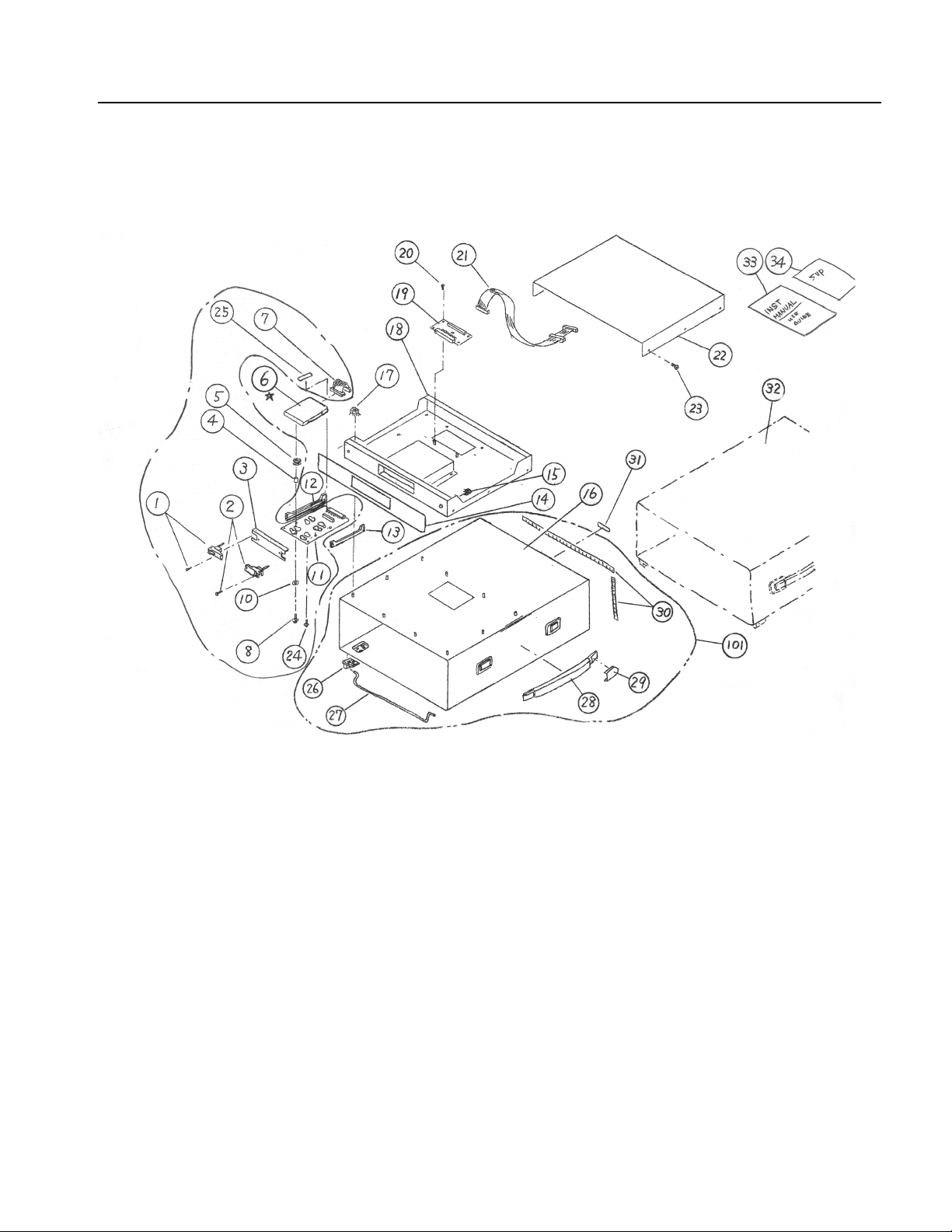
Kit Parts List
This kit contains parts and instructions that replace the Removable Hard Disk
Drive for AWG710B.
This Upgrade kit contains the parts shown in Table -1 Package List and Table -2
Parts List.
Table -1: Package List
Fig. &
index
number
1 PRE-ASSEMBLED CABINET & CHASSIS
-1 174-5006-00 1 CABLE, ASSY:FLAT,L=270MM
-2 334-1377-50 1 MARKER,IDENT:ID
-3 348-A144-00 4 DAMPER
-4 129-A593-00 4 SPACER,POST:PLASTIC 8MM
-5 210-A014-00 4 WASHER,PLAIN
-6 211-A159-00 4 SCREW MACHINE:M3X12MM,W/WASHER
071-1545-00 1 MANUAL,TECH;USER GUIDE;REMOVABLE HARD DISK
075-0849-00 1 MANUAL,TECH;INSTRUCTION FOR AWG710B ADD
Tektronix part
number Qty Name & description
DRIVE;AWG710BOpt11,AWG7UP 11
OP11,REMOVABLE HARD DISK DRIVE;AWG7UP 11
2
3
1
4
5
6
AWG7UP 11 Instructions Manual 1
Page 12

Introduction
Table -2: Parts List
Fig. &
index
number
1-1 105-1155-00 1 EJECTER,LOCK,LEFT
-2 105-1156-00 1 EJECTER,LOCK,RIGHT
-3 333-4492-00 1 PANEL,FRONT:RHD UNIT
-4 129-A593-00 4 SPACER,POST:PLASTIC 8MM
-5 348-A144-00 4 DAMPER
-6 119-B090-00 - HDD UNIT, Not Included
-7 174-5005-00 1 CABLE, ASSY:FLAT,L=40MM
-8 211-A159-00 4 SCREW MACHINE:M3X12MM,W/WASHER
-10 210-A014-00 4 WASHER,PLAIN
-11 671-5832-00 1 CIRCUIT BD ASSY:A510
-12 351-A174-00 1 GUIDE,CKT BD
-13 351-A173-00 1 GUIDE,CKT BD
-14 333-4493-00 1 PANEL,FRONT:MAIN CHASSIS
-15 220-0209-00 2 NUT,ASSEM WASHER:M4X7MM HEX
-16 437-0513-00 1 CABINET,ASSY,RHD:AWG710B
-17 220-0209-00 10 NUT,ASSEM WASHER:M4X7MM HEX
-18 441-2377-00 1 CHASSIS,ASSY:RHD
-19 671-5833-00 1 CIRCUIT BD ASSY:A520
-20 211-0751-00 4 SCREW MACHINE:M3X8MM
-21 174-5006-00 1 CABLE, ASSY:FLAT,L=270MM
-22 200-4896-00 1 COVER,TOP:RHD
-23 211-0751-00 4 SCREW, MACHINE:M3X8MM
-24 211-A152-00 2 SCREW,MACHINE:M2.5X8MM,NI PL
-26 348-1110-04 4 FOOT,CABINET:TEKBLUE
-27 348-0875-00 1 FRIPSTAND,CAB
-28 367-0247-01 1 HANDLE,CARRYING:11.54L
-29 200-2191-00 2 CAP,RETAINER:PLASTIC
-30 348-1314-00 122 (cm) GASKET,SHIELD:FINGER TYPE,BE-CU
-101 437-0515-00 1 CABINET,ASSY:CABINET FOOT,STAND & CARRYING HANDLE
-31 334-1377-50 1 MARKER,IDENT:ID
-33 071-1545-00 1 MANUAL,TECH;USER GUIDE;REMOVABLE HARD DISK
-34 075-0849-00 1 MANUAL,TECH;INSTRUCTION FOR AWG710B ADD
Tektronix part
number Qty Name & description
BUILD ON AWG710B RHD CABINET(437-0513-XX)
DRIVE;AWG710B0Opt11,AWG7UP 11
OP11,REMOVABLE HARD DISK DRIVE;AWG7UP 11
2 AWG7UP 11 Instructions Manual
Page 13
Introduction
.
Figure -1: Kit parts
AWG7UP 11 Instructions Manual 3
Page 14
Introduction
Equipment List
Table -3 lists the tools you will need to install the Removable Hard Disk Drive
Table -3: Tools required for kit installation
Item no. Name Description
1 Screwdriver handle Accepts Phillips–driver bits
2 #1 Phillips tip Phillips–driver bit for #1 screw size
3 #2 Phillips tip Phillips–driver bit for #2 screw size
4 Flat–blade screwdriver Screwdriver for removing standard-headed
screws
5 Pliers Standard tool
4 AWG7UP 11 Instructions Manual
Page 15

Installation Instructions
The following instructions explain how to install the AWG7UP 11 upgrade kit to
your AWG710B instrument. Execute these items in the order they are described.
Installation Procedure
To install the new Removable Hard Disk Drive Kit, perform the following steps.
1. Remove the cabinet.
2. Remove the A10 Connector board.
3. Remove the internal hard disk drive.
4. Exchange the IDE interface cable connecting to the CPU board, Flash disk and
Hard Disk Drive.
5. Reinstall the A10 Connector board.
6. Install the Hard Disk Drive removed from your AWG710B to the Removable
Hard Disk Assembly.
7. Install the new cabinet with the Removable Hard Disk chassis.
8. Connect the flat cable from the internal CPU board to the connector board in
the Removable Hard Disk chassis.
9. Checking the operation of the AWG710B.
10. Install the top cover and pasting the AWG7UP 11 Kit Label.
AWG7UP 11 Instructions Manual 5
Page 16

Installation Instructions
.
NOTE. When your AWG710B is rackmounted instrument, you need additional
working to remove the cabinet modules and to reinstall the rackmount assembly.
WARNING. Before doing this or any other procedure in this manual, read the
Safety Summary found at the beginning of this manual.
WARNING. Before doing any procedure in this subsection, disconnect the power
cord from the line voltage source. Failure to do so can cause serious injury or
death.
Cabinet removal
A10 Connector board
removal
CAUTION. Static discharge can damage any semiconductor component and hard
disk drive in this instruments.
You will need a screwdriver with a size #2 Phillips tip.
1. Remove the six screws at the rear of the cabinet which secure the two feet.
2. Grasp the left and right edges at the rear of the cabinet.
3. Pull upward to slide the cabinet off the generator . Take care not to bind or snag
the cabinet on the internal cabling as you remove it
To remove the internal Hard Disk Driv e, it is necessary to remove the A10
Connector board first. To remove the A10 Connector board do the following
substeps:
1. Orient the waveform generator so the bottom is on the work surface and the
front is facing you.
2. To remove the A10 Connector board, disconnect the following cables and
connectors.
Fan power cable at J310
Cable from the low-voltage power supply at J010
6 AWG7UP 11 Instructions Manual
Page 17

Installation Instructions
Cable to the PCI Backplane power supply at J320
J245 LCD Backlight, J225 TFT LCD and J102 Floppy disk driver
connector
Interconnect cables from CPU board at J100 CPU FDD, J110 CPU MISC,
J150 CPU VGA & COM1 and J220 CPU LCD
Interconnect cables to the Monitor Out at J152 and the A90 Key board at
J112
Interconnect cable from the PCI Interface at J200
Cables from the A20 Front Panel board at J154
IDE interface cable from the CPU board
3. Use a screwdriver with a size #2 Phillips tip to remove the five screws that
attach the A10 Connector board to the HDD bracket.
4. Lift the board up and out from the HDD bracket to complete the removal.
Figure -2: A10 Connector board removal
AWG7UP 11 Instructions Manual 7
Page 18

Installation Instructions
Internal Hard Disk Drive
removal
The internal Hard Disk Drive is beneath the HDD bracket. The following steps
describe how to remov e the Internal Hard Disk Dri ve. You will need a screwdriv er
with a size #2
1. Unplug the IDE interface cable connected to the IDE interface connector on the
Hard disk drive and the Flash disk.
2. Use a screwdriver with a size Phillips #2 tip to remove the four screws that
secure the hard disk and flash disk bracket to the chassis.
3. Remove the three screws that secure the hard disk drive to the bracket.
Phillips tip.
Flash disk
Hard disk
Figure -3: Internal Hard Disk Drive removal
Exchange the IDE interface
cable
8 AWG7UP 11 Instructions Manual
You need to exchange the IDE interface cable connecting the CPU board, the flash
disk and the hard disk drive.
1. Connect the IDE interface cable included in this kit to the flash disk.
NOTE. One end of the connector near an intermediate connector will be connected
to the CPU board. An intermediate connector is connected the Flash Disk. The rest
of connector will be connected to the Hard Disk Drive after the cabinet is installed.
Page 19

Installation Instructions
Reinstall the HDD bracket
and the A10 Connector
board
Install the Hard Disk Drive
To reinstall, do the procedure described “in reverse order .
1. Reinstall the HDD bracket without internal hard disk drive in the chassis.
2. Connect the one end of the IDE interface cable to the CPU board.
3. Reinstall the A10 Connector board. To reinstall, do the procedure described
“A10 Contouring board removal” section in the reverse order.
In the following procedure, reinstall the internal hard disk removed from the
AWG710B in the removable hard disk assembly.
1. T o remove the remo vable hard disk assembly , press the eject kno bs by pushing
the release button to the outside, then pull out the removable hard disk
assembly.
2. With four M3x12 screws, washers, spacers and dampers included in this kit,
attach the hard disk drive removed from inside of the AWG710B on the A510
board. (Recommended bolting torque is 0.6 Nm)
3. Connect the flat cable from the connector on the A510 board to the hard disk
drive.
Install the new cabinet
Connect the flat cable
1. Remove the four screws to remo v e the t op cover of the Remov able Hard Disk
cabinet.
2. T o install the new cabinet included in this kit, do the cabinet remov al procedure
in reverse order.
3. While reinstalling a cabinet, pull out the flat cable which have connected to the
CPU unit and the Flash Disk from the hole of the cabinet.
NOTE. When your instrument is rackmounted AWG710B:
Remove the handle, the handle caps, the flip stand and the feet from the new
cabinet. Refer to the AWG710B Arbitrary Waveform Generator Service
Manual for details.
1. After the new cabinet installation, connect a flat cable to the connector on the
A520 board.
NOTE. When your instrument is rackmounted AWG710B:
Reinstall the inside tracks and the rear brackets to a new cabinet from an
original cabinet.
AWG7UP 11 Instructions Manual 9
Page 20

Installation Instructions
Install the Removable Hard
Disk Assembly
Checking the operation
Pasting the AWG7UP 11 Kit
Label
1. Insert the Removable Hard Disk Assembly firmly to the back according to the
guide of the Removable Hard Disk Assembly bay.
2. Press the eject knobs to the inside to lock the Removable Hard Disk Assembly.
1. Connect the AC power cord.
2. Turn on the PRINCIPAL POWER SWITCH at the rear panel.
3. Push the front panel ON/STBY switch to power on the AWG710B.
4. Check that the AWG710B starts up, runs power-on self tests and all the
diagnostic tests are completed without error.
5. If there is any trouble, confirm whether connection of all cables and attachment
of the Removable Hard Disk Assembly are performed correctly.
6. Power off the AWG710B and disconnect the AC power cord.
1. Install the top cover with four screws.
2. Paste the AWG7UP 11 Kit label on the AWG710B rear panel.
3. Remove the protectiv e backing from the 334-13 77-50 kit l abel and place it on
the rear panel of the instrument.
10 AWG7UP 11 Instructions Manual
 Loading...