

Page 1

Programmer Manual
AWG710 & AWG710B
4GS/s / 4.2GS/s Arbitrary Waveform Generator
071-1414-00
This document supports firmware version 4.00 and above.
www.tektronix.com
Page 2

Copyright © Tektronix Ja pan, Ltd. All rights reserved.
Copyright © Tektronix, Inc. All rights reserved.
Tektronix products are covered by U.S. and foreign patents, issued and pending. Information in this publication
supercedes that in all previously published material. Specifications and price change privileges reserved.
Tektronix, Inc., P.O. Box 500, Beaverton, OR 97077
TEKTRONIX and TEK are registered trademarks of Tektronix, Inc.
Page 3

WARRANTY
Tektronix warrants that this product will be free from defects in materials and workmanship for a period of one (1)
year from the date of shipment. If any such product proves defective during this warranty period, Tektronix, at its
option, either will repair the defective product without charge for parts and labor, or will provide a replacement in
exchange for the defective product.
In order to obtain service under this warranty, Customer must notify Tektronix of the defect before the expiration of
the warranty period and make s uitable arrangements fo r the perform ance of service. Cu stomer shall be respo nsible for
packaging and shipping the defective product to the service center designated by Tektronix, with shipping charges
prepaid. T ektronix shall pay for the return of the product to Customer if the shipment is to a location within the country
in which the T e ktronix serv ice center is lo cated. Custo mer shall be respo nsible for payi ng all shippi ng char ges, duties,
taxes, and any other charges for products returned to any other locations.
This warranty shall not apply to any defect, failure or damage caused by improper use or improper or inadequate
maintenance and care. Tektronix shall not be obligated to furnish service under this warranty a) to repair damage
resulting from attempts by personnel other than Tektronix representatives to install, repair or service the product; b) to
repair damage resulting from improper use or connection to incompatible equipment; or c) to service a product that
has been modified or integrated with other products when the effect of such modification or integration increases the
time or difficulty of servicing the product.
THIS WARRANTY IS GIVEN BY TEKTRONIX WITH RESPECT TO THIS PRODUCT IN LIEU OF ANY
OTHER WARRANTIES, EXPRESSED OR IMPLIED. TEKTRONIX AND ITS VENDORS DISCLAIM ANY
IMPLIED WARRANT IES OF MERCHANTABILITY OR FITNESS FOR A PART ICULAR PURPOSE.
TEKTRONIX’ RESPONSIBILITY TO REPAIR OR REPLACE DEFECTIVE PRODUCTS IS THE SOLE
AND EXCLUSIVE REMEDY PROVIDED TO THE CUSTOMER FOR BREACH OF THIS WARRANTY.
TEKTRONIX AND ITS VENDORS WILL NOT BE LIABLE FOR ANY INDIRECT, SPECIAL,
INCIDENTAL, OR CONSEQUENTIAL DAMAGES IRRESPECTIVE OF WHETHER TEKTRONIX OR
THE VENDOR HAS ADVANCE NOTICE OF THE POSSIBILITY OF SUCH DAMAGES.
Page 4

Page 5

Tabl e o f Content s
Getting Started
Syntax and Commands
Table of Contents . . . . . . . . . . . . . . . . . . . . . . . . . . . . . . . . . . . . . . . . . . . . . . . . . . . . . . i
List of Figures . . . . . . . . . . . . . . . . . . . . . . . . . . . . . . . . . . . . . . . . . . . . . . . . . . . . . . . .v
List of Tables . . . . . . . . . . . . . . . . . . . . . . . . . . . . . . . . . . . . . . . . . . . . . . . . . . . . . . . . vii
Preface . . . . . . . . . . . . . . . . . . . . . . . . . . . . . . . . . . . . . . . . . . . . . . . . . . . . . . . . . . . . . ix
Related Manuals. . . . . . . . . . . . . . . . . . . . . . . . . . . . . . . . . . . . . . . . . . . . . . . . . . . . . . . ix
Getting Started . . . . . . . . . . . . . . . . . . . . . . . . . . . . . . . . . . . . . . . . . . . . . . . . . . . . . 1-1
Manual Overview. . . . . . . . . . . . . . . . . . . . . . . . . . . . . . . . . . . . . . . . . . . . . . . . . . . . . 1-1
Setting Up Remote Communications Using GPIB . . . . . . . . . . . . . . . . . . . . . . . . . . . 1-4
Setting Up Remote Communications Using Ethernet . . . . . . . . . . . . . . . . . . . . . . . . . 1-8
Command Syntax . . . . . . . . . . . . . . . . . . . . . . . . . . . . . . . . . . . . . . . . . . . . . . . . . . . 2-1
SCPI Commands and Queries . . . . . . . . . . . . . . . . . . . . . . . . . . . . . . . . . . . . . . . . . . . 2-2
IEEE 488.2 Common Commands . . . . . . . . . . . . . . . . . . . . . . . . . . . . . . . . . . . . . . . . 2-9
Constructed Mnemonics . . . . . . . . . . . . . . . . . . . . . . . . . . . . . . . . . . . . . . . . . . . . . . 2-10
Syntax Diagrams . . . . . . . . . . . . . . . . . . . . . . . . . . . . . . . . . . . . . . . . . . . . . . . . . . . . 2-12
Command Groups . . . . . . . . . . . . . . . . . . . . . . . . . . . . . . . . . . . . . . . . . . . . . . . . . . 2-13
Functional Groups . . . . . . . . . . . . . . . . . . . . . . . . . . . . . . . . . . . . . . . . . . . . . . . . . . . 2-13
Command Quick Reference. . . . . . . . . . . . . . . . . . . . . . . . . . . . . . . . . . . . . . . . . . . . 2-14
Command Summaries . . . . . . . . . . . . . . . . . . . . . . . . . . . . . . . . . . . . . . . . . . . . . . . . 2-16
Command Descriptions . . . . . . . . . . . . . . . . . . . . . . . . . . . . . . . . . . . . . . . . . . . . . 2-25
ABORt (No Query Form) . . . . . . . . . . . . . . . . . . . . . . . . . . . . . . . . . . . . . . . . . . . . . 2-25
:ABSTouch (No Query Form) . . . . . . . . . . . . . . . . . . . . . . . . . . . . . . . . . . . . . . . . . . 2-26
:AWGControl:CLOCk:SOURce (?) (only AWG710B). . . . . . . . . . . . . . . . . . . . . . . 2-28
:AWGControl:DOUTput[1][:STATe] (?) (except option02) . . . . . . . . . . . . . . . . . . . 2-29
:AWGControl:ENHanced:SEQuence[:JMODe] (?). . . . . . . . . . . . . . . . . . . . . . . . . . 2-30
:AWGControl:EVENt[:LOGic][:IMMediate] (No Query Form) . . . . . . . . . . . . . . . 2-30
:AWGControl:EVENt:SOFTware[:IMMediate] (No Query Form). . . . . . . . . . . . . . 2-31
:AWGControl:EVENt:TABLe[:IMMediate] (No Query Form) . . . . . . . . . . . . . . . . 2-32
:AWGControl:FG:FREQuency[:CW|:FIXed] (?) . . . . . . . . . . . . . . . . . . . . . . . . . . . 2-32
:AWGControl:FG[1]:FUNCtion[:SHAPe] (?). . . . . . . . . . . . . . . . . . . . . . . . . . . . . . 2-33
:AWGControl:FG[1]:POLarity (?). . . . . . . . . . . . . . . . . . . . . . . . . . . . . . . . . . . . . . . 2-34
:AWGControl:FG[1]:PULSe:DCYCle (?). . . . . . . . . . . . . . . . . . . . . . . . . . . . . . . . . 2-35
:AWGControl:FG[:STATe] (?). . . . . . . . . . . . . . . . . . . . . . . . . . . . . . . . . . . . . . . . . . 2-36
:AWGControl:FG[1]:VOLTage[:LEVel][:IMMediate][:AMPLitude] (?) . . . . . . . . . 2-37
:AWGControl:FG[1]:VOLTage[:LEVel][:IMMediate]:OFFSet (?)
(except option02) . . . . . . . . . . . . . . . . . . . . . . . . . . . . . . . . . . . . . . . . . . . . . . . . . . . 2-38
:AWGControl:MIX[:STATe] (?) . . . . . . . . . . . . . . . . . . . . . . . . . . . . . . . . . . . . . . . . 2-38
:AWGControl:RMODe (?). . . . . . . . . . . . . . . . . . . . . . . . . . . . . . . . . . . . . . . . . . . . . 2-39
:AWGControl:RSTate? (Query Only) . . . . . . . . . . . . . . . . . . . . . . . . . . . . . . . . . . . . 2-40
:AWGControl:RUN[:IMMediate] (No Query Form). . . . . . . . . . . . . . . . . . . . . . . . . 2-41
AWG710 & AWG710B Arbitrary Waveform Generator Programmer Manual i
Page 6

Table of Contents
:AWGControl:SREStore (No Query Form) . . . . . . . . . . . . . . . . . . . . . . . . . . . . . . . . 2-42
:AWGControl:SSAVe (No Query Form). . . . . . . . . . . . . . . . . . . . . . . . . . . . . . . . . . . 2-42
:AWGControl:STOP[:IMMediate] (No Query Form). . . . . . . . . . . . . . . . . . . . . . . . . 2-43
:AWGControl:SYNChronous:ADDRess (?) (AWG 710B only) . . . . . . . . . . . . . . . . 2-44
:AWGControl:SYNChronous:CALibration (No Query Form) (AWG710B only) . . 2-44
:AWGControl:SYNChronous:CONNect (?) (AWG710B only) . . . . . . . . . . . . . . . . . 2-45
:AWGControl:SYNChronous:MASTer[:STATe] (?) (AWG710B only). . . . . . . . . . . 2-46
:AWGControl:SYNChronous:SLAVe[:STATe] (?) (AWG710B only) . . . . . . . . . . . . 2-47
*CAL? (Query Only) . . . . . . . . . . . . . . . . . . . . . . . . . . . . . . . . . . . . . . . . . . . . . . . . . 2-48
:CALibration[:ALL] (?) . . . . . . . . . . . . . . . . . . . . . . . . . . . . . . . . . . . . . . . . . . . . . . . 2-48
*CLS (No Query Form) . . . . . . . . . . . . . . . . . . . . . . . . . . . . . . . . . . . . . . . . . . . . . . . 2-50
:DIAGnostic:DATA? (Query Only). . . . . . . . . . . . . . . . . . . . . . . . . . . . . . . . . . . . . . . 2-50
:DIAGnostic[:IMMediate] (?). . . . . . . . . . . . . . . . . . . . . . . . . . . . . . . . . . . . . . . . . . . 2-51
:DIAGnostic:SELect (?) . . . . . . . . . . . . . . . . . . . . . . . . . . . . . . . . . . . . . . . . . . . . . . . 2-52
:DISPlay:ENABle (?) . . . . . . . . . . . . . . . . . . . . . . . . . . . . . . . . . . . . . . . . . . . . . . . . . 2-53
:DISPlay:HILight:COLor (?) . . . . . . . . . . . . . . . . . . . . . . . . . . . . . . . . . . . . . . . . . . . 2-54
*ESE (?) . . . . . . . . . . . . . . . . . . . . . . . . . . . . . . . . . . . . . . . . . . . . . . . . . . . . . . . . . . . 2-54
*ESR? (Query Only). . . . . . . . . . . . . . . . . . . . . . . . . . . . . . . . . . . . . . . . . . . . . . . . . . 2-55
:HCOPy:DESTination (No Query Form) . . . . . . . . . . . . . . . . . . . . . . . . . . . . . . . . . . 2-56
:HCOPy:DEVice:COLor (?) . . . . . . . . . . . . . . . . . . . . . . . . . . . . . . . . . . . . . . . . . . . . 2-56
:HCOPy:DEVice:LANGuage (?) . . . . . . . . . . . . . . . . . . . . . . . . . . . . . . . . . . . . . . . . 2-57
:HCOPy[:IMMediate] (No Query Form) . . . . . . . . . . . . . . . . . . . . . . . . . . . . . . . . . . 2-58
:HCOPy:SDUMp[:IMMediate] (No Query Form) . . . . . . . . . . . . . . . . . . . . . . . . . . . 2-58
*IDN? (Query Only). . . . . . . . . . . . . . . . . . . . . . . . . . . . . . . . . . . . . . . . . . . . . . . . . . 2-59
:MMEMory:CATalog? (Query Only) . . . . . . . . . . . . . . . . . . . . . . . . . . . . . . . . . . . . . 2-60
:MMEMory:CDIRectory (?). . . . . . . . . . . . . . . . . . . . . . . . . . . . . . . . . . . . . . . . . . . . 2-61
:MMEMory:CLOSe (No Query Form). . . . . . . . . . . . . . . . . . . . . . . . . . . . . . . . . . . . 2-61
:MMEMory:COPY (No Query Form) . . . . . . . . . . . . . . . . . . . . . . . . . . . . . . . . . . . . 2-62
:MMEMory:DATA (?). . . . . . . . . . . . . . . . . . . . . . . . . . . . . . . . . . . . . . . . . . . . . . . . . 2-62
:MMEMory:DELete (No Query Form). . . . . . . . . . . . . . . . . . . . . . . . . . . . . . . . . . . . 2-63
:MMEMory:FEED (?). . . . . . . . . . . . . . . . . . . . . . . . . . . . . . . . . . . . . . . . . . . . . . . . . 2-64
:MMEMory:INITialize (No Query Form). . . . . . . . . . . . . . . . . . . . . . . . . . . . . . . . . . 2-65
:MMEMory:MDIRectory (No Query Form). . . . . . . . . . . . . . . . . . . . . . . . . . . . . . . . 2-66
:MMEMory:MOVE (No Query Form) . . . . . . . . . . . . . . . . . . . . . . . . . . . . . . . . . . . . 2-67
:MMEMory:MSIS (?) . . . . . . . . . . . . . . . . . . . . . . . . . . . . . . . . . . . . . . . . . . . . . . . . . 2-68
:MMEMory:NAME (?). . . . . . . . . . . . . . . . . . . . . . . . . . . . . . . . . . . . . . . . . . . . . . . . 2-68
:MMEMory:OPEN (No Query Form). . . . . . . . . . . . . . . . . . . . . . . . . . . . . . . . . . . . . 2-69
*OPC (?) . . . . . . . . . . . . . . . . . . . . . . . . . . . . . . . . . . . . . . . . . . . . . . . . . . . . . . . . . . . 2-70
*OPT? (Query Only). . . . . . . . . . . . . . . . . . . . . . . . . . . . . . . . . . . . . . . . . . . . . . . . . . 2-70
:OUTPut[1]:FILTer[:LPASs]:FREQuency (?) (except option02). . . . . . . . . . . . . . . . 2-71
:OUTPut[1]:ISTate (?). . . . . . . . . . . . . . . . . . . . . . . . . . . . . . . . . . . . . . . . . . . . . . . . . 2-72
:OUTPut[1][:STATe] (?) . . . . . . . . . . . . . . . . . . . . . . . . . . . . . . . . . . . . . . . . . . . . . . . 2-72
:OUTPut[1]:MARKer[:STATe] (?) (AWG710B only). . . . . . . . . . . . . . . . . . . . . . . . 2-73
*PSC (?) . . . . . . . . . . . . . . . . . . . . . . . . . . . . . . . . . . . . . . . . . . . . . . . . . . . . . . . . . . . 2-74
*RST (No Query Form) . . . . . . . . . . . . . . . . . . . . . . . . . . . . . . . . . . . . . . . . . . . . . . . 2-75
[:SOURce[1]]:FREQuency[:CW|FIXed] (?). . . . . . . . . . . . . . . . . . . . . . . . . . . . . . . . 2-75
[:SOURce[1]]:FUNCtion:USER (?) . . . . . . . . . . . . . . . . . . . . . . . . . . . . . . . . . . . . . . 2-76
[:SOURce[1]]:MARKer[1|2]:VOLTage[:LEVel][:IMMediate]:HIGH (?) . . . . . . . . . 2-77
[:SOURce[1]]:MARKer[1|2]:VOLTage[:LEVel][:IMMediate]:LOW (?). . . . . . . . . . 2-78
[:SOURce[1]]:ROSCillator:SOURce (?) . . . . . . . . . . . . . . . . . . . . . . . . . . . . . . . . . . 2-79
[:SOURce[1]]:VOLTage[:LEVel][:IMMediate][:AMPLitude] (?) . . . . . . . . . . . . . . . 2-80
ii AWG710 & AWG710B Arbitrary Waveform Generator Programmer Manual
Page 7

Table of Contents
[:SOURce[1]]:VOLTage[:LEVel][:IMMediate]:OFFSet (?) (except option02) . . . . 2-81
*SRE (?). . . . . . . . . . . . . . . . . . . . . . . . . . . . . . . . . . . . . . . . . . . . . . . . . . . . . . . . . . . 2-82
:STATus:OPERation:CONDition? (Query Only) . . . . . . . . . . . . . . . . . . . . . . . . . . . 2-82
:STATus:OPERation:ENABle (?) . . . . . . . . . . . . . . . . . . . . . . . . . . . . . . . . . . . . . . . 2-83
:STATus:OPERation[:EVENt]? (Query Only). . . . . . . . . . . . . . . . . . . . . . . . . . . . . . 2-84
:STATus:PRESet (No Query Form). . . . . . . . . . . . . . . . . . . . . . . . . . . . . . . . . . . . . . 2-84
:STATus:QUEStionable:CONDition? (Query Only). . . . . . . . . . . . . . . . . . . . . . . . . 2-84
:STATus:QUEStionable:ENABle (?) . . . . . . . . . . . . . . . . . . . . . . . . . . . . . . . . . . . . . 2-85
:STATus:QUEStionable[:EVENt]? (Query Only) . . . . . . . . . . . . . . . . . . . . . . . . . . . 2-86
*STB? (Query Only) . . . . . . . . . . . . . . . . . . . . . . . . . . . . . . . . . . . . . . . . . . . . . . . . . 2-86
:SYSTem:BEEPer[:IMMediate] (No Query Form). . . . . . . . . . . . . . . . . . . . . . . . . . 2-87
:SYSTem:COMMunicate:LAN:DHCP[:CLIent]:LEASe:TIME (?). . . . . . . . . . . . . 2-88
:SYSTem:COMMunicate:LAN:DHCP[:CLIent][:STATe] (?). . . . . . . . . . . . . . . . . . 2-88
:SYSTem:COMMunicate:LAN:FTP[:SERVer][:STATe] (?). . . . . . . . . . . . . . . . . . . 2-89
:SYSTem:COMMunicate:LAN:FTP[:SERVer]:VERSion (?). . . . . . . . . . . . . . . . . . 2-90
:SYSTem:COMMunicate:LAN:GATeway[1|2|3]:ADDRess (?) . . . . . . . . . . . . . . . . 2-90
:SYSTem:COMMunicate:LAN:NFS:TLIMit (?) . . . . . . . . . . . . . . . . . . . . . . . . . . . 2-91
:SYSTem:COMMunicate:LAN:PING? (Query Only). . . . . . . . . . . . . . . . . . . . . . . . 2-92
:SYSTem:COMMunicate:LAN:RDEVice[1|2|3]:ADDRess (?) . . . . . . . . . . . . . . . . 2-92
:SYSTem:COMMunicate:LAN:RDEVice[1|2|3]:FSYStem (?). . . . . . . . . . . . . . . . . 2-93
:SYSTem:C OMMunicate:LAN:RDEVice[1|2|3]:NAME (?). . . . . . . . . . . . . . . . . . . 2-94
:SYSTem:COMMunicate:LAN:RDEVice[1|2|3]:PROTocol (?) . . . . . . . . . . . . . . . . 2-94
:SYSTem:COMMunicate:LAN:RDEVice[1|2|3][:STATe] (?). . . . . . . . . . . . . . . . . . 2-95
:SYSTem:COMMunicate:LAN[:SELF]:ADDRess (?) . . . . . . . . . . . . . . . . . . . . . . . 2-96
:SYSTem:COMMunicate:LAN[:SELF]:MADDress? (Query Only) . . . . . . . . . . . . 2-96
:SYSTem:COMMunicate:LAN[:SELF]:SMASk (?). . . . . . . . . . . . . . . . . . . . . . . . . 2-97
:SYSTem:DATE (?) . . . . . . . . . . . . . . . . . . . . . . . . . . . . . . . . . . . . . . . . . . . . . . . . . . 2-98
:SYSTem:ERRor[:NEXT]? (Query Only). . . . . . . . . . . . . . . . . . . . . . . . . . . . . . . . . 2-98
:SYSTem:KDIRrection (?). . . . . . . . . . . . . . . . . . . . . . . . . . . . . . . . . . . . . . . . . . . . . 2-99
:SYSTem:KEYBoard[:TYPE] (?) . . . . . . . . . . . . . . . . . . . . . . . . . . . . . . . . . . . . . . 2-100
:SYSTem:KLOCk (?). . . . . . . . . . . . . . . . . . . . . . . . . . . . . . . . . . . . . . . . . . . . . . . . 2-100
:SYSTem:SECurity:IMMediate (No Query Form) . . . . . . . . . . . . . . . . . . . . . . . . . 2-101
:SYSTem:TIME (?) . . . . . . . . . . . . . . . . . . . . . . . . . . . . . . . . . . . . . . . . . . . . . . . . . 2-102
:SYSTem:UPTime? (Query Only) . . . . . . . . . . . . . . . . . . . . . . . . . . . . . . . . . . . . . . 2-102
:SYSTem:VERSion? (Query Only). . . . . . . . . . . . . . . . . . . . . . . . . . . . . . . . . . . . . 2-103
*TRG (No Query Form) . . . . . . . . . . . . . . . . . . . . . . . . . . . . . . . . . . . . . . . . . . . . . 2-103
:TRIGger[:SEQuence][:IMMediate] (No Query Form). . . . . . . . . . . . . . . . . . . . . . 2-104
:TRIGger[:SEQuence]:IMPedance (?). . . . . . . . . . . . . . . . . . . . . . . . . . . . . . . . . . . 2-104
:TRIGger[:SEQuence]:LEVel (?). . . . . . . . . . . . . . . . . . . . . . . . . . . . . . . . . . . . . . . 2-105
:TRIGger[:SEQuence]:POLarity (?) . . . . . . . . . . . . . . . . . . . . . . . . . . . . . . . . . . . . 2-106
:TRIGger[:SEQuence]:SLOPe (?) . . . . . . . . . . . . . . . . . . . . . . . . . . . . . . . . . . . . . . 2-107
:TRIGger[:SEQuence]:SOURce (?). . . . . . . . . . . . . . . . . . . . . . . . . . . . . . . . . . . . . 2-108
:TRIGger[:SEQuence]:TIMer (?) . . . . . . . . . . . . . . . . . . . . . . . . . . . . . . . . . . . . . . 2-108
*TST? (Query Only) . . . . . . . . . . . . . . . . . . . . . . . . . . . . . . . . . . . . . . . . . . . . . . . . 2-109
*WAI (No Query Form). . . . . . . . . . . . . . . . . . . . . . . . . . . . . . . . . . . . . . . . . . . . . . 2-110
Retrieving Response Messages . . . . . . . . . . . . . . . . . . . . . . . . . . . . . . . . . . . . . . . 2-111
Data Transfer . . . . . . . . . . . . . . . . . . . . . . . . . . . . . . . . . . . . . . . . . . . . . . . . . . . . . 2-113
Data File. . . . . . . . . . . . . . . . . . . . . . . . . . . . . . . . . . . . . . . . . . . . . . . . . . . . . . . . . . 2-113
About Waveform and Pattern Files . . . . . . . . . . . . . . . . . . . . . . . . . . . . . . . . . . . . . 2-114
Data Transfer Procedures. . . . . . . . . . . . . . . . . . . . . . . . . . . . . . . . . . . . . . . . . . . . . 2-121
AWG710 & AWG710B Arbitrary Waveform Generator Programmer Manual iii
Page 8

Table of Contents
Status and Events
Status and Event Reporting . . . . . . . . . . . . . . . . . . . . . . . . . . . . . . . . . . . . . . . . . . . 3-1
Status Reporting Structure . . . . . . . . . . . . . . . . . . . . . . . . . . . . . . . . . . . . . . . . . . . . . . 3-1
Registers . . . . . . . . . . . . . . . . . . . . . . . . . . . . . . . . . . . . . . . . . . . . . . . . . . . . . . . . . . . .3-4
Status Registers. . . . . . . . . . . . . . . . . . . . . . . . . . . . . . . . . . . . . . . . . . . . . . . . . . . . . . . 3-4
Enable Registers . . . . . . . . . . . . . . . . . . . . . . . . . . . . . . . . . . . . . . . . . . . . . . . . . . . . . . 3-8
Queues. . . . . . . . . . . . . . . . . . . . . . . . . . . . . . . . . . . . . . . . . . . . . . . . . . . . . . . . . . . . . 3-10
Status and Event Processing Sequence. . . . . . . . . . . . . . . . . . . . . . . . . . . . . . . . . . . . 3-11
I/O Status and Event Screen . . . . . . . . . . . . . . . . . . . . . . . . . . . . . . . . . . . . . . . . . . . . 3-13
Synchronizing Execution . . . . . . . . . . . . . . . . . . . . . . . . . . . . . . . . . . . . . . . . . . . . . . 3-14
Messages . . . . . . . . . . . . . . . . . . . . . . . . . . . . . . . . . . . . . . . . . . . . . . . . . . . . . . . . . . . 3-14
Messages and Codes . . . . . . . . . . . . . . . . . . . . . . . . . . . . . . . . . . . . . . . . . . . . . . . . . 3-15
Command Errors. . . . . . . . . . . . . . . . . . . . . . . . . . . . . . . . . . . . . . . . . . . . . . . . . . . . . 3-16
Execution Errors . . . . . . . . . . . . . . . . . . . . . . . . . . . . . . . . . . . . . . . . . . . . . . . . . . . . . 3-18
Device Specific Errors. . . . . . . . . . . . . . . . . . . . . . . . . . . . . . . . . . . . . . . . . . . . . . . . . 3-20
Query Errors . . . . . . . . . . . . . . . . . . . . . . . . . . . . . . . . . . . . . . . . . . . . . . . . . . . . . . . . 3-21
Power–On Events . . . . . . . . . . . . . . . . . . . . . . . . . . . . . . . . . . . . . . . . . . . . . . . . . . . . 3-21
User Request Events . . . . . . . . . . . . . . . . . . . . . . . . . . . . . . . . . . . . . . . . . . . . . . . . . . 3-21
Request Control Events. . . . . . . . . . . . . . . . . . . . . . . . . . . . . . . . . . . . . . . . . . . . . . . . 3-22
Operation Complete Events . . . . . . . . . . . . . . . . . . . . . . . . . . . . . . . . . . . . . . . . . . . . 3-22
Device Errors. . . . . . . . . . . . . . . . . . . . . . . . . . . . . . . . . . . . . . . . . . . . . . . . . . . . . . . . 3-23
Examples
Appendices
Glossary and Index
Programming Examples . . . . . . . . . . . . . . . . . . . . . . . . . . . . . . . . . . . . . . . . . . . . . . 4-1
Appendix A: Character Charts . . . . . . . . . . . . . . . . . . . . . . . . . . . . . . . . . . . . . . . . A-1
Appendix B: GPIB Interface Specification . . . . . . . . . . . . . . . . . . . . . . . . . . . . . . B-1
Interface Functions . . . . . . . . . . . . . . . . . . . . . . . . . . . . . . . . . . . . . . . . . . . . . . . . . . . B-1
Interface Messages . . . . . . . . . . . . . . . . . . . . . . . . . . . . . . . . . . . . . . . . . . . . . . . . . . . B-3
Appendix C: Network Interface Specification . . . . . . . . . . . . . . . . . . . . . . . . . . . . C-1
Appendix D: SCPI Conformance Information . . . . . . . . . . . . . . . . . . . . . . . . . . . D-1
Appendix E: Factory Initialization Settings . . . . . . . . . . . . . . . . . . . . . . . . . . . . . E-1
Glossary . . . . . . . . . . . . . . . . . . . . . . . . . . . . . . . . . . . . . . . . . . . . . . . . . . . . . Glossary-1
Index . . . . . . . . . . . . . . . . . . . . . . . . . . . . . . . . . . . . . . . . . . . . . . . . . . . . . . . . . . . . . . 1-1
iv AWG710 & AWG710B Arbitrary Waveform Generator Programmer Manual
Page 9

List of Figures
List of Figures
Figure 1-1: Common message elements . . . . . . . . . . . . . . . . . . . . . . . . . . . . . . . . . 1-1
Figure 1-2: Functional groupings and alphabetical list of commands . . . . . . . . . 1-2
Figure 1-3: Basic operation of status and events reporting . . . . . . . . . . . . . . . . . 1-3
Figure 1-4: The floppy disk . . . . . . . . . . . . . . . . . . . . . . . . . . . . . . . . . . . . . . . . . . . 1-3
Figure 1-5: GPIB connector location . . . . . . . . . . . . . . . . . . . . . . . . . . . . . . . . . . . 1-4
Figure 1-6: How to stack GPIB connectors . . . . . . . . . . . . . . . . . . . . . . . . . . . . . . 1-5
Figure 1-7: Typical GPIB network configurations . . . . . . . . . . . . . . . . . . . . . . . . 1-6
Figure 1-8: Selecting the GPIB configuration and address . . . . . . . . . . . . . . . . . . 1-7
Figure 1-9: Ethernet port location . . . . . . . . . . . . . . . . . . . . . . . . . . . . . . . . . . . . . . 1-8
Figure 1-10: Setting the Network parameters . . . . . . . . . . . . . . . . . . . . . . . . . . . 1-10
Figure 1-11: Message box to indicate the establishment of communication . . . 1-11
Figure 2-1: Example of SCPI subsystem hierarchy tree . . . . . . . . . . . . . . . . . . . . 2-2
Figure 2-2: Example of abbreviating a command . . . . . . . . . . . . . . . . . . . . . . . . . 2-5
Figure 2-3: Example of chaining commands and queries . . . . . . . . . . . . . . . . . . . 2-6
Figure 2-4: Example of omitting root and lower–level nodes in a chained message .
2-6
Figure 2-5: Typical syntax diagrams . . . . . . . . . . . . . . . . . . . . . . . . . . . . . . . . . . . 2-12
Figure 2-6: ABSTouch arguments and Front panel . . . . . . . . . . . . . . . . . . . . . . 2-27
Figure 2-7: Retrieving response messages . . . . . . . . . . . . . . . . . . . . . . . . . . . . . 2-111
Figure 2-8: The Waveform file format . . . . . . . . . . . . . . . . . . . . . . . . . . . . . . . . 2-115
Figure 2-9: The Pattern File format . . . . . . . . . . . . . . . . . . . . . . . . . . . . . . . . . . 2-116
Figure 2-10: The Sequence File format . . . . . . . . . . . . . . . . . . . . . . . . . . . . . . . . 2-117
Figure 2-11: The Equation File format . . . . . . . . . . . . . . . . . . . . . . . . . . . . . . . . 2-119
Figure 2-12: The Code Convert File format . . . . . . . . . . . . . . . . . . . . . . . . . . . . 2-120
Figure 3-1: Error and Event handling process overview . . . . . . . . . . . . . . . . . . . 3-2
Figure 3-2: The Status Byte Register (SBR) . . . . . . . . . . . . . . . . . . . . . . . . . . . . . . 3-5
Figure 3-3: The Standard Event Status Register (SESR) . . . . . . . . . . . . . . . . . . . 3-6
Figure 3-4: The Operation Condition Register (OCR) . . . . . . . . . . . . . . . . . . . . . 3-7
Figure 3-5: The Questionable Condition Register (QCR) . . . . . . . . . . . . . . . . . . . 3-7
Figure 3-6: The Event Status Enable Register (ESER) . . . . . . . . . . . . . . . . . . . . . 3-8
Figure 3-7: The Service Request Enable Register (SRER) . . . . . . . . . . . . . . . . . . 3-9
Figure 3-8: The Operation Enable Register (OENR) . . . . . . . . . . . . . . . . . . . . . . 3-9
Figure 3-9: The Questionable Enable Register (QENR) . . . . . . . . . . . . . . . . . . . . 3-9
Figure 3-10: Status and Event processing sequence — Operation status block 3-11
Figure 3-11: Status and Event processing sequence — Questionable status block . .
3-11
Figure 3-12: Status and Event processing sequence — Standard/Event status block
3-12
Figure 3-13: Status and Event screen . . . . . . . . . . . . . . . . . . . . . . . . . . . . . . . . . . 3-13
Figure 4-1: Equipment needed to run the GPIB example programs . . . . . . . . . . 4-1
AWG710 & AWG710B Arbitrary Waveform Generator Programmer Manual v
Page 10

List of Figures
vi AWG710 & AWG710B Arbitrary Waveform Generator Programmer Manual
Page 11

List of Tables
List of Tables
Table 2-1: BNF symbols and meanings . . . . . . . . . . . . . . . . . . . . . . . . . . . . . . . . . . 2-1
Table 2-2: Query response examples . . . . . . . . . . . . . . . . . . . . . . . . . . . . . . . . . . . . 2-3
Table 2-3: Parameter types used in syntax descriptions . . . . . . . . . . . . . . . . . . . . 2-4
Table 2-4: Functional groups in the AWG command set . . . . . . . . . . . . . . . . . . 2-13
Table 2-5: AWG Control commands . . . . . . . . . . . . . . . . . . . . . . . . . . . . . . . . . . 2-16
Table 2-6: Calibration commands . . . . . . . . . . . . . . . . . . . . . . . . . . . . . . . . . . . . . 2-17
Table 2-7: Diagnostic commands . . . . . . . . . . . . . . . . . . . . . . . . . . . . . . . . . . . . . . 2-17
Table 2-8: Display commands . . . . . . . . . . . . . . . . . . . . . . . . . . . . . . . . . . . . . . . . 2-18
Table 2-9: Hardcopy commands . . . . . . . . . . . . . . . . . . . . . . . . . . . . . . . . . . . . . . 2-18
Table 2-10: Mass storage in AWG710 and AWG710B . . . . . . . . . . . . . . . . . . . . 2-19
Table 2-11: Mass Memory commands . . . . . . . . . . . . . . . . . . . . . . . . . . . . . . . . . 2-19
Table 2-12: Output commands . . . . . . . . . . . . . . . . . . . . . . . . . . . . . . . . . . . . . . . 2-20
Table 2-13: Source commands . . . . . . . . . . . . . . . . . . . . . . . . . . . . . . . . . . . . . . . . 2-20
Table 2-14: Status commands . . . . . . . . . . . . . . . . . . . . . . . . . . . . . . . . . . . . . . . . 2-21
Table 2-15: Synchronization commands . . . . . . . . . . . . . . . . . . . . . . . . . . . . . . . . 2-21
Table 2-16: System commands . . . . . . . . . . . . . . . . . . . . . . . . . . . . . . . . . . . . . . . . 2-22
Table 2-17: Trigger commands . . . . . . . . . . . . . . . . . . . . . . . . . . . . . . . . . . . . . . . 2-23
Table 2-18: Selecting run modes . . . . . . . . . . . . . . . . . . . . . . . . . . . . . . . . . . . . . . 2-40
Table 2-19: Self–test routines . . . . . . . . . . . . . . . . . . . . . . . . . . . . . . . . . . . . . . . . . 2-52
Table 3-1: SBR bit functions . . . . . . . . . . . . . . . . . . . . . . . . . . . . . . . . . . . . . . . . . . 3-5
Table 3-2: SESR bit functions . . . . . . . . . . . . . . . . . . . . . . . . . . . . . . . . . . . . . . . . . 3-6
Table 3-3: OCR bit functions . . . . . . . . . . . . . . . . . . . . . . . . . . . . . . . . . . . . . . . . . . 3-7
Table 3-4: QCR bit functions . . . . . . . . . . . . . . . . . . . . . . . . . . . . . . . . . . . . . . . . . . 3-7
Table 3-5: Definition of event codes . . . . . . . . . . . . . . . . . . . . . . . . . . . . . . . . . . . 3-15
Table 3-6: Command errors . . . . . . . . . . . . . . . . . . . . . . . . . . . . . . . . . . . . . . . . . . 3-16
Table 3-7: Execution errors . . . . . . . . . . . . . . . . . . . . . . . . . . . . . . . . . . . . . . . . . . 3-18
Table 3-8: Device specific errors . . . . . . . . . . . . . . . . . . . . . . . . . . . . . . . . . . . . . . 3-20
Table 3-9: Query errors . . . . . . . . . . . . . . . . . . . . . . . . . . . . . . . . . . . . . . . . . . . . . 3-21
Table 3-10: Power–on events . . . . . . . . . . . . . . . . . . . . . . . . . . . . . . . . . . . . . . . . . 3-21
Table 3-11: User request events . . . . . . . . . . . . . . . . . . . . . . . . . . . . . . . . . . . . . . . 3-21
Table 3-12: Request control events . . . . . . . . . . . . . . . . . . . . . . . . . . . . . . . . . . . . 3-22
Table 3-13: Operation complete events . . . . . . . . . . . . . . . . . . . . . . . . . . . . . . . . . 3-22
Table 3-14: Device errors . . . . . . . . . . . . . . . . . . . . . . . . . . . . . . . . . . . . . . . . . . . 3-23
Table A-1: The AWG character set . . . . . . . . . . . . . . . . . . . . . . . . . . . . . . . . . . . . . A-1
Table A-2: ASCII & GPIB code chart . . . . . . . . . . . . . . . . . . . . . . . . . . . . . . . . . . A-2
Table B-1: GPIB interface function implementation . . . . . . . . . . . . . . . . . . . . . . . B-1
Table B-2: AWG standard interface message . . . . . . . . . . . . . . . . . . . . . . . . . . . . B-3
Table D-1: SCPI conformance information . . . . . . . . . . . . . . . . . . . . . . . . . . . . . . D-1
Table E-1: Factory initialization settings . . . . . . . . . . . . . . . . . . . . . . . . . . . . . . . . E-1
AWG710 & AWG710B Arbitrary Waveform Generator Programmer Manual vii
Page 12

List of Tables
viii AWG710 & AWG710B Arbitrary Waveform Generator Programmer Manual
Page 13

Preface
This is the programmer manual for the AWG710 and AWG710B Arbitrary
Waveform Generators. This manual provides information necessary for operating
the instrument over both the G eneral Purpose Interface Bus (GPIB) and E thernet
interfaces.
This manual provides the following information:
The Getting Starte d section desc ribes ho w to connect and se t up the wa veform
generator for remote operation.
The Syntax and Commands section defines the command syntax and
processing conventions and describes each command in the waveform
generator command set.
The Status and Events section explains the status information and event
messages reported by the waveform generator.
The Programming Examples section describe s how to u se the Sample Pr ogram
floppy disk supplied with the waveform generator.
The Appendices section contains various tables of reference information.
Related Manuals
The Glossary and Index section contains a glossary of common terms and an
index to this manual.
Other docum entation for the waveform generator includes:
The AWG710 & AWG710B Arbitrary Waveform Generator User Manual
(Tektronix part number 071–1413–00) describes the operation of the
instrument.
AWG710&AWG710B Arbitrary Waveform Generator Programmer Manual ix
Page 14

Preface
x AWG710&AWG710B Arbitrary Waveform Generator Programmer Manual
Page 15

Getting Started
Page 16

Page 17

Getting Started
Manual Overview
The AWG710 Arbitrary Waveform Generator has GPIB and
10Base-T/100Base-TX Ethernet interface capability. You can write computer
programs that remote ly se t the fron t panel controls or that transf er w aveform data.
To help you get started with programming the waveform generator, this section
includes the following subs ections:
Manual Overview - summarizes the type of programming information
contained in each major section in this manual.
Setting Up Remote Communications Using GPIB - describes how to connect
the waveform generator to a controller through the GPIB interface, and how to
set the appropriate front panel controls.
Setting Up Remote Communications Using Ethernet - describes how to
connect the wa veform gener ator to a contro ller using the Et hernet interf ace and
how to set the appropriate front panel controls.
A summary of the information provided in each major section of this manual
follows:
Syntax and Commands
The Command Syntax subsection, which begins on page 2-1, describes the
structure and content of the messages your program sends to the waveform
generator. You can use the Standard Commands for Programmable Instruments
(SCPI) and IEEE 488.2 Common Commands. Figure 1-1 is an example of the
syntax and command parts diagrams used in the Command Syntax subsection.
Command parts
Header
FUNCtion:USER
n
i
c
s
o
e
n
m
M
Syntax diagram
FUNCtion USER
:
Figure 1-1: Common message elements
Comma
"FILE1","FLOPpy"
Space
<space>
Arguments
<file_name>
,
<msus>
AWG710&AWG710B Arbitrary Waveform Generator Programmer Manual 1-1
Page 18

Getting Started
The Command Syntax subsection also describes the result of each comm and, and
provides examples of how you might use it. The Command Groups subsection,
which begins on page 2-13, provides a command list by functional area. The
Command Descriptions subsection, which begins on page 2-25, arranges
commands alphabetically. Figure 1-2 illustrates the two kinds of command lists.
Tr ig ge r
Diagnostic Commands
Calibration Commands
D
D
D
Commands Grouped in Functional Areas and Commands Listed Alphabetically
AWG C o n t rol C o m m a nds
C
C
:AWGControl:DOUTput:[:STATe]
C
:AWGControl:EVENt:LOGic[:IMMediate]
:AWGControl:RMODe
:AWGControl:RSTate?
:AWGControl:RUN[:IMMediate]
TRIGg
Figure 1-2: Functional groupings and alphabetical list of commands
Status and Events
Reporting
The program may request information from the waveform generator. The
wavef orm generator p rovides inf ormation in th e form of status an d error message s.
Figure 1-3 on page 1-3 illustrates the basic operation of this system.
The Status and Eve nts Reporting subsect io n, whi ch begins on page 3-1, describes
how to use t he st at us r eporting functions that conform to SCPI and IEEE-488.2 in
your programs.
AWG Con tro l:R MOD e
AWGControl:EVENt:LOGic[:IMMediate]
S
S
G
E
AWGControl:DOUTput[:STATe]
G
Syntax: . . .
E
Group: . . .
Examples: . . .
1-2 AWG710&AWG710B Arbitrary Waveform Generator Programmer Manual
Page 19
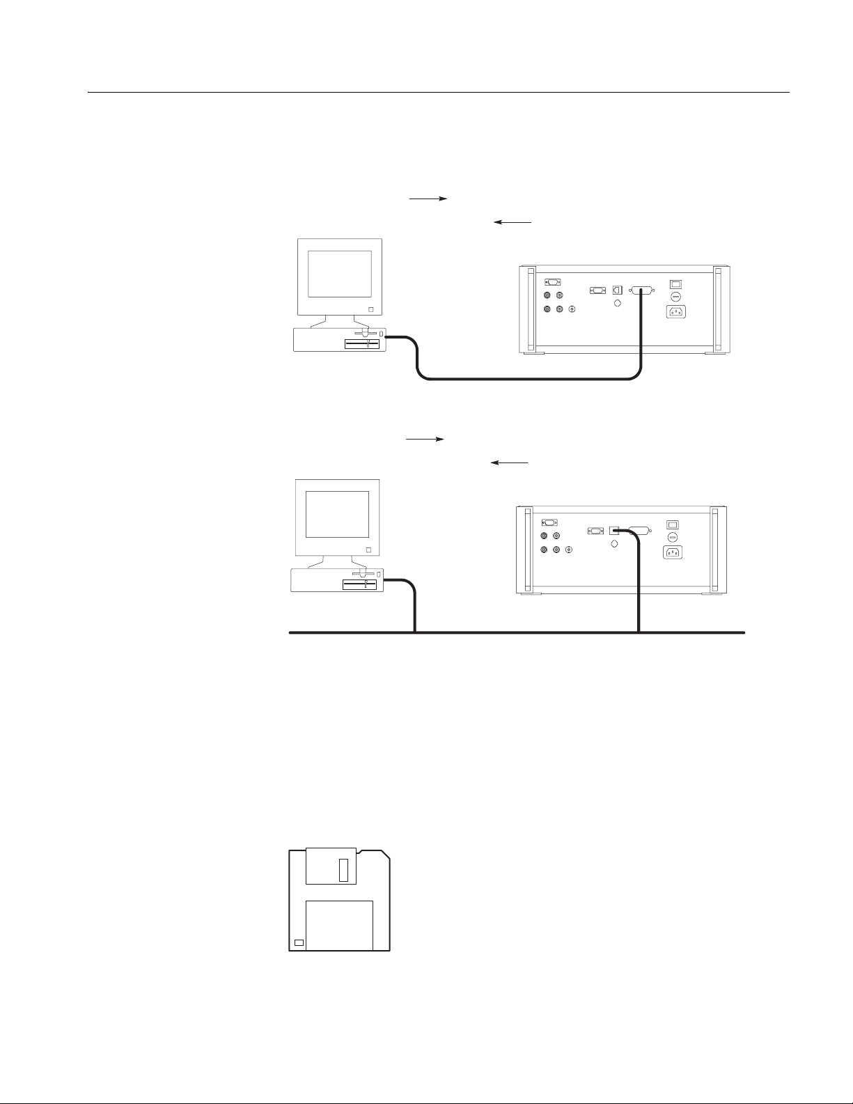
Your program requests
status and event reports.
Controller
Your program requests
status and event reports.
Getting Started
AWG sends status and event reports.
Waveform generator (rear panel)
GPIB cable
Programming Examples
Controller
Lan cable
LAN (Ethernet) or Hub
AWG sends status and event reports.
Waveform generator (rear panel)
Lan cable
Figure 1-3: Basic operation of status and events reporting
The Programming Examples section, which begins on page 4-1, provides some
sample waveform generator programs. A floppy disk (see Figure 1-4) is supplied
with this manual. The disk contains a Microsoft Visual C++ and Visual BASIC
source–code version of each program.
AWG Examp le
Programs
Figure 1-4: The floppy disk
AWG710&AWG710B Arbitrary Waveform Generator Programmer Manual 1-3
Page 20

Getting Started
Setting Up Remote Communications Using GPIB
For remote operations, the instrument must be connected to the controller.
The wav ef orm generator has a 24– pin GPIB connector on its rear panel, as shown
in Figure 1-5. This connector has a D–type shell and conforms to IEEE Std
488.1–1987.
Attach an IEEE Std 488.1–1987 GPIB cable (Tektronix Part Number
012–0991–XX) to the GPIB connector.
GPIB connector
Figure 1-5: GPIB connector location
1-4 AWG710&AWG710B Arbitrary Waveform Generator Programmer Manual
Page 21
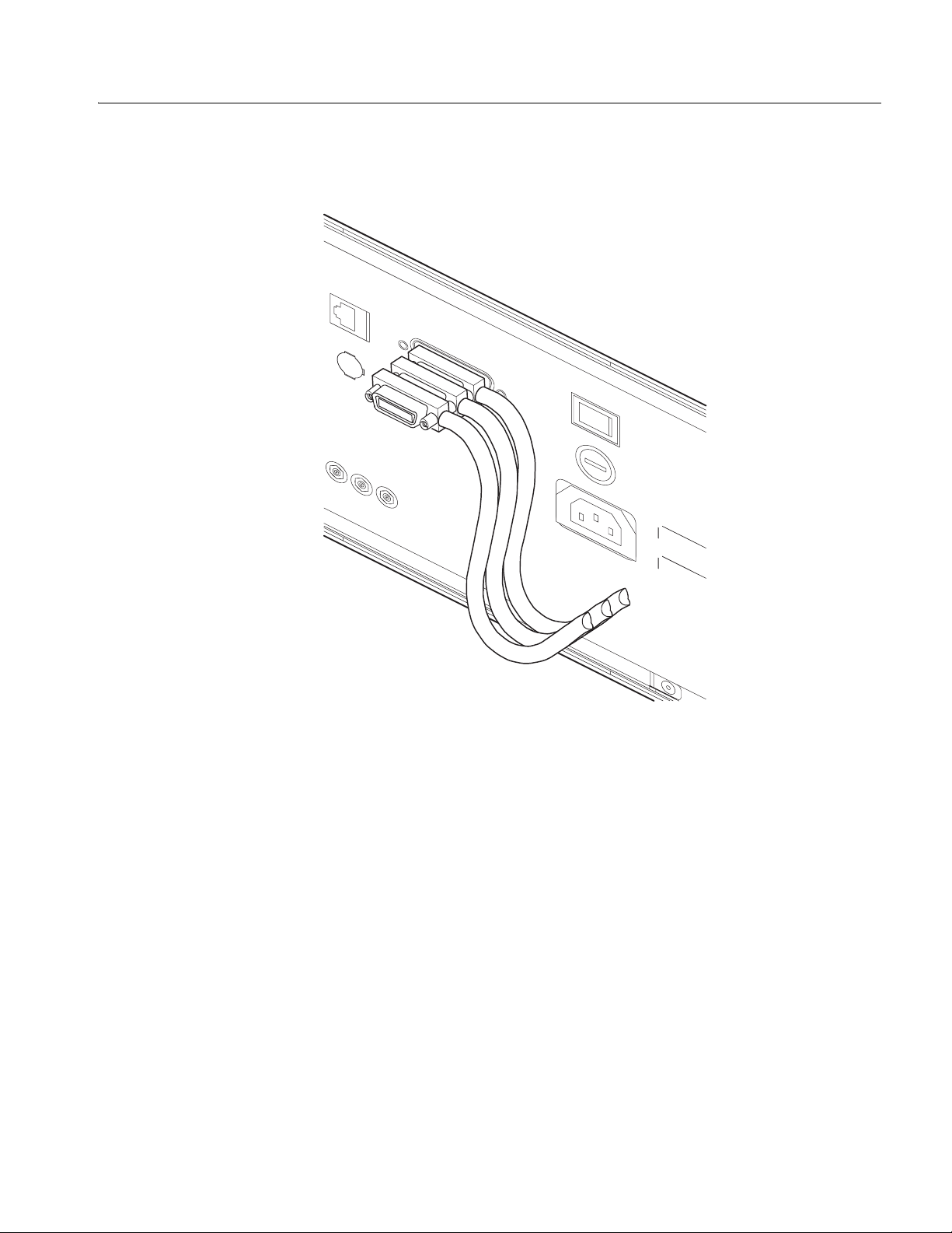
Stack GPIB connectors, if needed, as shown in Figure 1-6.
Getting Started
Figure 1-6: How to stack GPIB connectors
AWG710&AWG710B Arbitrary Waveform Generator Programmer Manual 1-5
Page 22
Getting Started
GPIB Requirements
Follow these rules when you use your waveform generator with a GPIB network:
Assign a unique de vice addr ess to each de vice on the b us. Two devices can not
share the same device address.
Do not connect more than 15 devices to one bus.
Connect one device for every 2 meters (6 feet) of cable used.
Do not use more than 20 meters (65 feet) of cable to connect devices to a bus.
While using the network, turn on at least two–thirds of th e devices on the
network.
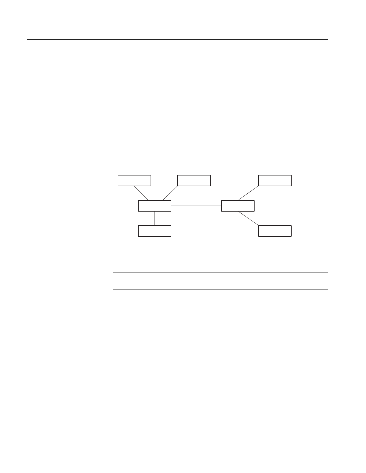
Connect the devices on t he network in a st ar or l in ear configurat ion, as sho wn
in Figure 1-7. Do not use loop or parallel configurations.
GPIB Device
GPIB Device
GPIB Device
GPIB Device
GPIB Device
GPIB Device
GPIB Device
Setting the GPIB
Parameters
Figure 1-7: Typical GPIB network configurations
NOTE. Appendix C: Network Interface Specification provides more information
about the GPIB configuration of the waveform generator.
You must set the GPIB parameters of the waveform generator t o match the
configuration of the bus. F ollow the step s be low to set up the waveform ge ner at or
for the GPIB interface.
1. Press the UTILITY button to display the Utility screen.
2. Press the Comm menu button at the bottom of the screen.
3. Move the cursor to the Remote Control field using the up/down ("/#) arrow
buttons, then select GPIB using the left/right (z/!) arrow buttons.
4. Move the cursor to the GPIB Configura tion field using the up/down ("/#)
arrow buttons, then select Talk/Listen using either the general purpose knob
or the left/right (z/!) arrow buttons. See Figure 1-8 on page 1-7.
1-6 AWG710&AWG710B Arbitrary Waveform Generator Programmer Manual
Page 23
Getting Started
5. Move the cursor to the GPIB Address field using the down (#) arrow button.
Set the address using either the general purpose knob or the keypad.
Figure 1-8: Selecting the GPIB configuration and address
The waveform generator is set up for bidirectional communication with your
controller. Do the following to isolate the waveform generator from the bus:
Select Off Bus in the GPIB Configuration field.
This selection disables all communication with the controller.
AWG710&AWG710B Arbitrary Waveform Generator Programmer Manual 1-7
Page 24
Getting Started
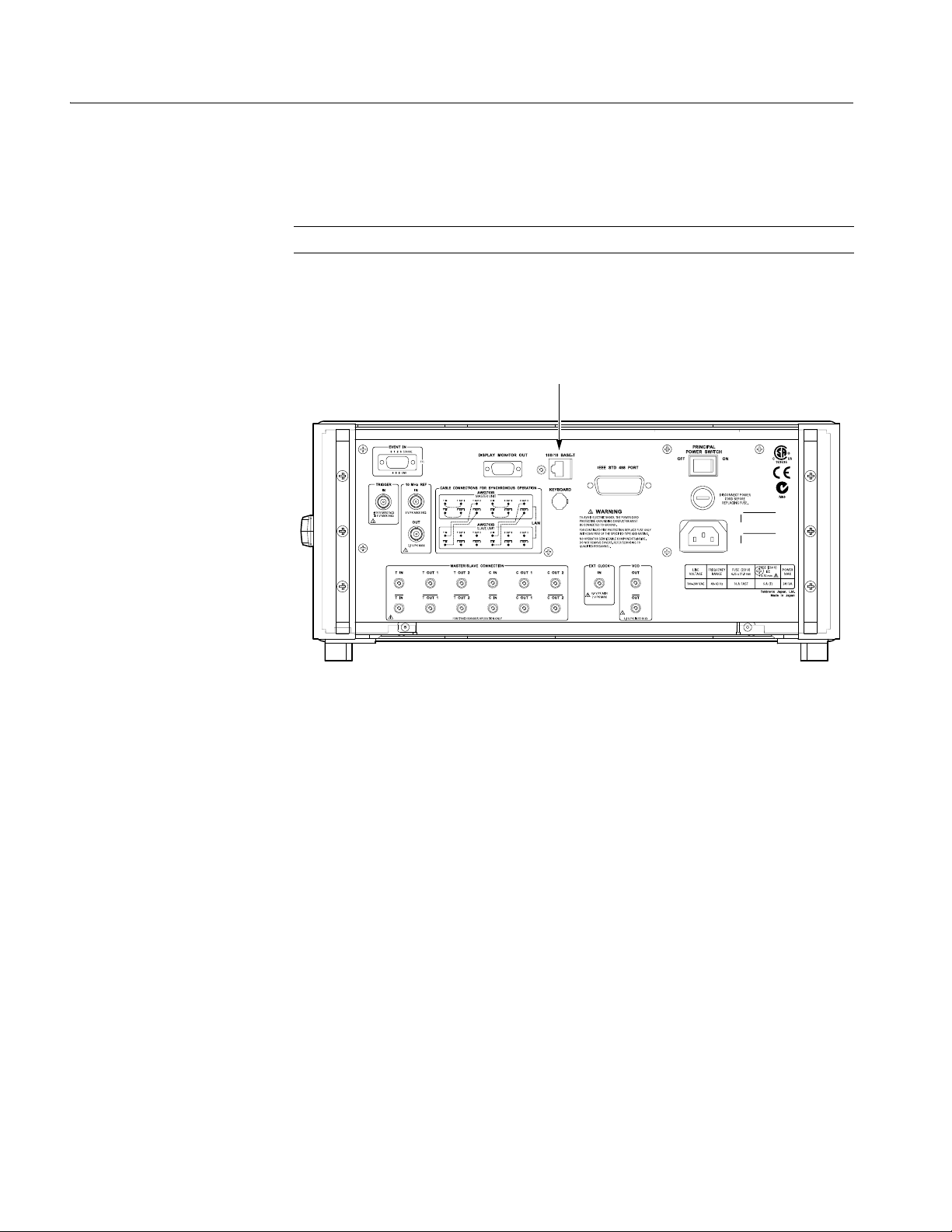
Setting Up Remote Communications Using Ethernet
NOTE. For remote operations, the instrument must be connected to the controller.
The wave for m gene ra tor has an Ethernet (10Base-T/ 100Ba se -Tx) por t on the rear
panel as shown in Figures 1-9.
Attach an Ethernet cable to the Ethernet port.
Ethernet port
Figure 1-9: Ethernet port location
1-8 AWG710&AWG710B Arbitrary Waveform Generator Programmer Manual
Page 25

Getting Started
Setting the Network
Parameters
You must set the network parameters of the waveform generator to match the
configuration of the net work. After you ha v e set these par ameters, you can contro l
the waveform generator throug h the Ethern et interface.
1. Press the UTILITY button to display the Utility screen.
2. Press the Comm menu button at the bottom of the screen.
3. Move the cursor to the Remote Control field using the up/down ("/#) arrow
buttons, then select Network using the left/right (z/!) arrow buttons.
4. Move the cursor to the Network IP Address field using the up/down ("/#)
arrow buttons, then press the Edit... button and set the address using the
keypad. See Figure 1-10 on page 1-10.
Manual operation:
a. Move the cursor to the DHCP Client field using the up/do wn ("/#) arrow
buttons, then press Disabled using the left/right (z/!) arrow buttons.
b. Move the cursor to the IP Address field using the up/down ("/#) arrow
buttons, then press the Edit... button.
c. Set the IP Address in IP Address dialog box.
d. If necessary, use the Subnet Mask field to set the address.
Using DHCP:
e. Move the cursor to the DHCP Client field us ing the up/down ("/#) arrow
buttons, then press Enabled using the left/right (z/!) arrow buttons.
f. AWG710 sends an acquisition request, then the server sends the address.
The address is displayed in the IP Address fie ld.
5. If necessary , use the Destination Network and Gateway Address fields to set
the destination network and the address.
You need to set the gateway address when the remote computers are
connecting to an other network t hat i s connected to th e n et w o rk via a gate w ay.
You can set up to three gateways.
Set the FTP server to Enabled for access to the hard disk sy stem of the
instrument from a remote computer.
If you are not familiar with the network setup, consult with your network
administrator.
AWG710&AWG710B Arbitrary Waveform Generator Programmer Manual 1-9
Page 26

Getting Started
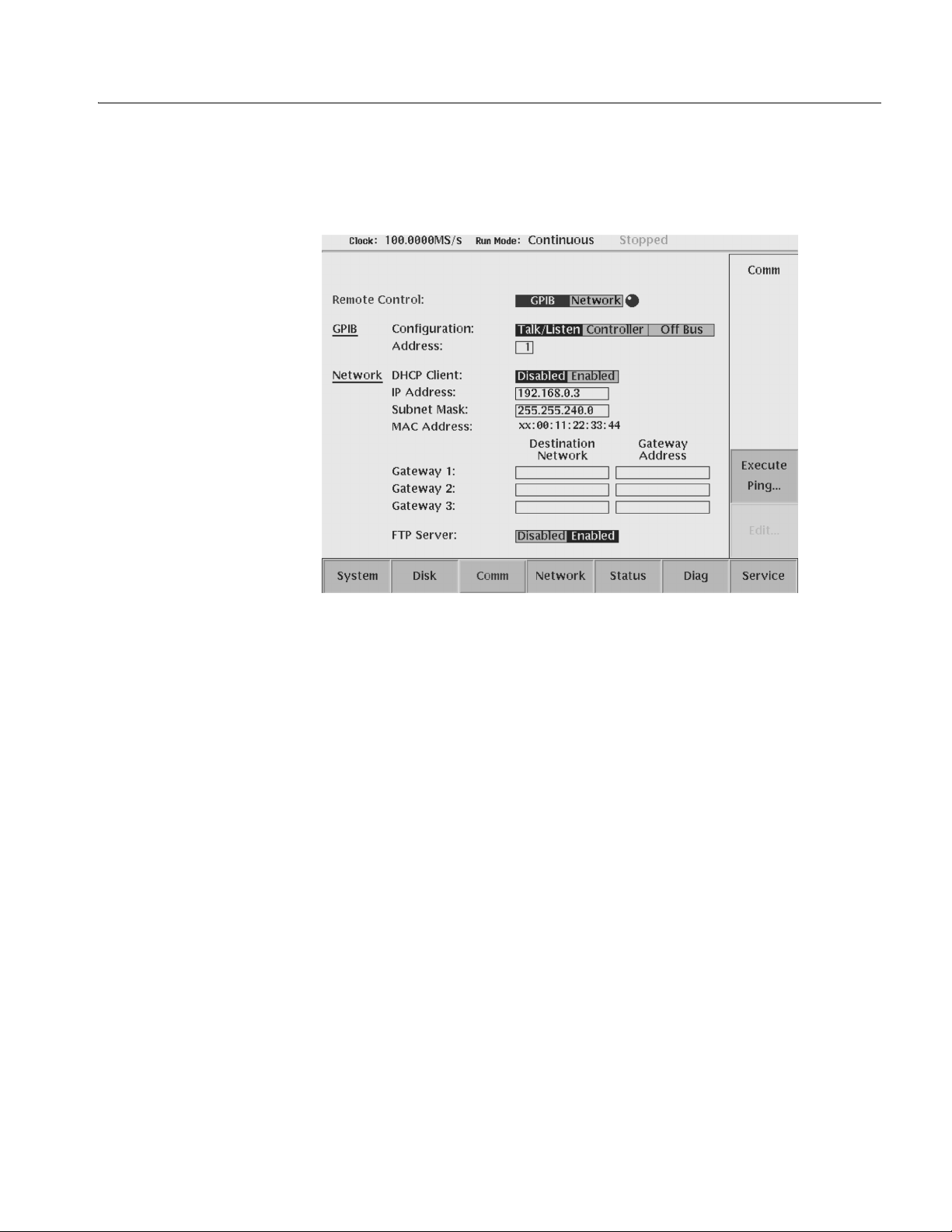
Network
parameters
Figure 1-10: Setting the Network parameters
1-10 AWG710&AWG710B Arbitrary Waveform Generator Programmer Manual
Page 27

Getting Started
Testing the Network
Connection
After completing the connection and settings, verify that the waveform generator
can recognize the network and the remote computers, or if the network can
recognize the waveform generator. Follow these steps to use the “ping” command
to verify that the instrument can communicate with the network:
1. Press the UTILITY button to display the Utility screen.
2. Press the Network or Comm bottom menu button.
3. Press the Execute Ping side button to display a dialog box.
4. Enter the IP address of the remote computer in the dialog box, and then push
the OK side button.
The ping command sends a pac k et t o t h e r emot e c omput er spe ci fied by the IP
address. When the computer receives the packet, it sends the packet back to the
sender (waveform generator).
When the waveform generator can communicate with the remote computer
through the network the message in Figure 1-11 displays. If communication
failed, the message box displays an error message such as "no response
from...".
5. Repeat steps 2 and 3 to verify the connection for other remote computers on
the network .
Figure 1-11: Message box to indicate the establishment of communication
AWG710&AWG710B Arbitrary Waveform Generator Programmer Manual 1-11
Page 28

Getting Started
1-12 AWG710&AWG710B Arbitrary Waveform Generator Programmer Manual
Page 29

Syntax and Commands
Page 30

Page 31

Command Syntax
This section contains general information about command structure and syntax
usage. You should familiarize yourself with this material before using the
waveform generator command descriptions.
This manual describes commands and queries using Backus–Naur Form (BNF)
notation. Table 2-1 defines standard BNF symbols.
Table 2-1: BNF symbols and meanings
Symbol Meaning
<> Defined element
::= Is defined as
|Exclusive OR
{} Group; one element is required
[] Optional; can be omitted
. . . Previous element(s) may be repeated
() Comment
AWG710&AWG710B Arbitrary Waveform Generator Programmer Manual 2-1
Page 32

Command Syntax
SCPI Commands and Queries
The waveform generator uses a command language based on the SCPI standard.
The SCPI (Standard Commands for Programmable Instruments) standard was
created by a consortium to provide guidelines for remote programming of
instruments. These guidelines provide a consistent programming environment for
instrument control and data transfe r. This environment use s defined progr amming
messages, i nstrument responses and data formats that operate across all S CPI
instruments, regardless of manufacturer.
The SCPI language is based on a hierarchical or tree structure that represents a
subsystem (see Figu re 2-1). The top le v el of t he tree is the root node; it is fo llo wed
by one or more lower–level nodes.
TRIGger
SEQuence
POLarity SOURceLEVe
Root node
Lower-level
nodes
Figure 2-1: Example of SCPI subsystem hierarchy tree
You can create commands and queries from these subsystem hierarchy trees.
Commands specify actions for the instrument to perform. Queries return
measurement data and information about parameter settings.
2-2 AWG710&AWG710B Arbitrary Waveform Generator Programmer Manual
Page 33

Command Syntax
Creating Commands
Creating Queries
Query Responses
SCPI commands are created by stringing together the nodes of a subsystem
hierarchy and separating each node by a colon.
In Figure 2-1 on page 2-2, TRIGger is the root node and SEQuence, LEVel,
POLarity, and SOURce are lower–level nodes. To create an SCPI command, start
with the root node TRIGger and move down the tree structure adding nodes until
you reach the end of a branch. Most commands and some queries hav e parameter s;
you must include a v a lue for these parameters. The command descriptions, which
begin on page 2-25, list the valid values for all parameters.
For example, :TRIGger:SEQuence:SOURce EXTernal is a valid SCPI command
created from the hierarchy tree in Figure 2-1 on page 2-2.
To create a query, start at the root node of a tree structure, move down to the end
of a branch, and add a question mark. :TRIGger:SEQuence:SOURce? is an
example of a valid SCPI query using the hierarchy tree in Figure 2-1 on page 2-2.
The query causes the waveform g ene rat or to r eturn information abou t its status or
settings. When a query is sent to the waveform generator, only the values are
returned. When th e returned v alue is a mne monic, it is note d in abbre viated format ,
as shown in Table 2-2.
Table 2-2: Query response examples
Query Response
:SOURce:VOLTage:AMPLitude? 1.000
:AWGControl:RMODe? CONT
A few queries also initiate an operation ac tion before re turning information. For
example, the *CAL? query runs a calibration.
AWG710&AWG710B Arbitrary Waveform Generator Programmer Manual 2-3
Page 34

Command Syntax
Parameter Types
Parameters ar e indicated by angle brackets , such as <f ile_name>. There a re sev eral
different types of parameters, as listed in Table 2-3. The parameter type is listed
after the parameter . Some para meter types are define d specifically fo r the A WG710
command set and some are defined by SCPI.
Table 2-3: Parameter types used in syntax descriptions
Parameter Type Description Example
arbitrary block A block of data bytes #512234xxxxx...
where 5 indicates that the
following 5 digits (12234)
specify the length of the data in
bytes;
xxxxx... indicates the data
or
#0xxxxx...<LF><&EOI>
boolean Boolean numbers or values ON or ¸ 0 : x<= -0.5, 0.5 <= x
OFF or 0 : -0.5 < x < 0.5
discrete A list of specific values MIN, MAX
binary Binary numbers #B0110
octal Octal numbers #Q75, #Q3
hexadecimal Hexadecimal numbers
(0-9, A- F)
NR1 numeric Integers 0, 1, 15, -1
NR2
numeric Decimal numbers 1.2, 3.141516, -6.5
numeric Floating point numbers 3.1415E-9, -16.1E5
NR3
NRf
numeric Flexible decimal number that
may be type NR1, NR2, or NR3
numeric_value Flexible decimal number that
may be type NR1, NR2, NR3,
or specific value (MINimum,
MAXmum).
string
Alphanumeric characters
(must be within quotation
marks)
#HAA, #H1
See NR1, NR2, NR3 examples
in this table
See NR1, NR2, NR3 examples
in this table
“Testing 1, 2, 3”
About MIN, MAX
You can use MINimum and MAXimum keywords in addition to Numeric in the
commands with “numer ic_value” param eter. You can set the minimum value or
the maximum v alue by the use of this k eywords. You can query the minimum v alue
or the maximum value at tha time.
2-4 AWG710&AWG710B Arbitrary Waveform Generator Programmer Manual
Page 35

Command Syntax
Special Characters
Abbreviating Commands,
Queries, and Parameters
The Line Feed (LF) ch ar ac ter or t he New Line (NL) char act er ( AS CII 10) , and all
characters in the ran ge of ASCII 127–2 55 are defined as special cha rac ters . These
characters are used in arbitrary block arguments only; using these characters in
other parts of any command yields unpredictable results.
You can abbreviate most SCPI commands, queries , and parame ters t o an accept ed
short form. This manual shows these commands as a combination of upper and
lower case letters. The upper case letters indicate the accepted short form of a
command, as shown in Figure 2-2. The acc ept ed short form and th e l ong for m ar e
equivalent and request the same action of the instrument.
Long form of a
command
Accepted short form
of a command
:SOURce1:FREQuency 100
Minimum information needed
for accepted short form
:SOUR:FREQ 100
Figure 2-2: Example of abbreviating a command
NOTE. The numeric suffix of a command or query may be included in either the
long form or short form; the AWG710 will default to “1” if no suffix is used.
AWG710&AWG710B Arbitrary Waveform Generator Programmer Manual 2-5
Page 36

Command Syntax
Chaining Commands
andQueries
You can chain several commands or queries together into a single message. To
create a chained message, first create a command or query, then add a semicolon
(;), and finally add more commands or q uer ies and semicolons un ti l you are done.
If the command following a semicolon is a root node, precede it with a colon (:).
Figure 2-3 illustrates a chained message consisting of several commands and
queries. The chained messa ge should end in a command or query, not a semicolon.
Responses to any queries in your message are separated by semicolons.
:SOUR:FREQ:FIX 100;:OUTP:STAT ON;:SOUR:VOLT:AMPL?;:TRIG:SEQ:LEV?
First command
The response from this chained message might be:
Second command
Response from first query
First query
100;1.2
Second query
Response from second query
Figure 2-3: Example of chaining commands and queries
If a command or query has the same root and lower–level nodes as the previous
command or query, you can omit these nodes. In Figure 2-4, t he seco nd comma nd
has the same root node (SEQuence) as the first command, so these nodes can be
omitted.
:TRIG:SEQ:LEV 2.5;:TRIG:SEQ:SLOP POS;:TRIG:SEQ:SOUR EXT
Identical root and lower-level nodes
:TRIG:SEQ:LEV 2.5;SLOP POS;SOUR EXT
First command
Additional commands
(omitted the root nodes)
Figure 2-4: Example of omitting root and lower–level nodes in a chained message
2-6 AWG710&AWG710B Arbitrary Waveform Generator Programmer Manual
Page 37

Command Syntax
Unit and SI Prefix
If the decimal n um er ic argument refe rs to voltage, fr equ ency, impedanc e, o r t ime,
you can express it using SI units instead of using the scaled explicit point input
value format <NR3>. (SI units are units that conform to the System International
d’Unites standard.) For e xample, you c an use the i nput format 200 mV or 1.0 MHz
instead of 200.0E-3 or 1.0E+6, respectively, to specify voltage or frequency.
You can omit the unit, but you must include the SI unit prefix. You can use either
upper or lowercase units.
V or v for voltage
Hz, HZ, or hz for frequency
ohm, OHM, or Ohm for impedance
s or S for time
In the case of angle, you can use RADian and DEGree. The def ault unit is RADian.
The SI prefixes, which must be included, are shown below. Note that either lower
or upper case prefixes can be used.
SI prefix * p/P n/N u/U m/M k/K m/M g/G
Corresponding power 10
* Note that the prefix m/M indicates 10-3 when the decimal numeric argument
denotes voltage or time, but indicates 10
-12
10
-9
10
-6
6
-3
10
when it denotes frequency.
10
3
10
6
10
9
* Note that the prefix u/U is used instead of ”µ”.
Use mV for V, and MHz for Hz.
AWG710&AWG710B Arbitrary Waveform Generator Programmer Manual 2-7
Page 38

Command Syntax
General Rules
Here are th ree general rules for using SCPI comm ands, quer i es, and parameters:
You can use single (‘ ’) or dou ble (“ ”) quot ation ma rks for quoted strin gs, b u t
you cannot use both types of quotation marks for the same string.
correct: “This string uses quotation marks correctly.”
correct: ‘This string also uses quotation marks correctly.’
incorrect: “This string does not use quotation marks correctly.’
You can use upper case, lower case, or a mixture of both cases for all
commands, queries, and parameters.
:OUTPUT:FILTER:LPASS:FREQUENCY 200MHZ
is the same as
:output:filter:lpass:frequency 200MHz
and
:OUTPUT:filter:LPASS:frequency 200MHz
NOTE. Literal strings (quoted) are case sensitive. For example: file names.
No embedded spaces are allowed between or within nodes.
correct: :OUTPUT:FILTER:LPASS:FREQUENCY 200MHZ
incorrect: :OUTPUT: FILTER: LPASS:FREQUENCY 200MHZ
2-8 AWG710&AWG710B Arbitrary Waveform Generator Programmer Manual
Page 39

IEEE 488.2 Common Commands
ANSI/IEEE Standard 488.2 defines the codes, formats, protocols, and usage of
common commands and queries used on the interface between the controller and
the instruments. The waveform generator complies with this standard .
The syntax for an IEEE 488.2 common command is an asterisk (*) followed by a
command and, optionally, a space and parameter value. The syntax for an
IEEE 488.2 common query is an asterisk (*) followed by a query and a question
mark. All of the common commands and queries are included in the Syntax and
Commands section of this manual. The following are examples of common
commands:
*ESE 16
*CLS
The following are examples of common queries:
*ESR?
Command Syntax
*IDN?
AWG710&AWG710B Arbitrary Waveform Generator Programmer Manual 2-9
Page 40

Command Syntax
Constructed Mnemonics
Some command headers list a range of mnemonics. When constructing the
command, you select one mnemonic from the list. You then use the mnemonic in
the command just as you do any other mnemonic. Mnemonic ranges can be
presented in any of the following formats:
MNEMonic[a|b|c]. The v a lues a, b, an d c re presen t the act ual li st of valid
selections. You cannot list more than one value.
For example, for the command :SYSTem:COMMunicate:LAN:GATe-
way[1|2|3]:ADDRess, the gateway mnemonic could be any of the
following:GATeway1, GATeway2, or GATeway3. Theref ore, a va lid usage
of this command would be: SYSTem:COMMunicate:LAN:GATeway1:
ADDRess.
MNEMonic<n>. The value of <n> is the upper range of vali d suff ix es. If th e
numeric suffix is omitted, the waveform generator uses the default value
of “1”.
Source Channel
Mnemonics
Output Channel
Mnemonics
Direct D/A Output
Mnemonics
(Except option02)
These commands spec ify the sour ce channel t o use as a mnemonic in the header.
Symbol Meaning
SOURce1 CH1 signal of waveform generator
These commands specify the output channel to use as a mnemonic in the header.
Symbol Meaning
OUTPut1 CH1 analog signal output
These commands specify the dire ct D/A converte r output to use as a mn emonic in
the header.
Symbol Meaning
DOUTput1 Direct output from CH1 D/A converter
2-10 AWG710&AWG710B Arbitrary Waveform Generator Programmer Manual
Page 41

Command Syntax
Gateway Mnemonics
Marker Mnemonics
Remote Device
Mnemonics
These commands specify the gateway to use as a mnemonic in the header.
Symbol Meaning
GATeway1 Gateway 1
GATeway2 Gateway 2
GATeway3 Gateway 3
These commands specify the marker to use as a mnemonic in the header.
Symbol Meaning
MARKer1 The signal for the marker 1
MARKer2 The signal for the marker 2
These commands specify the remote device to use as a mnemonic in the header.
Symbol Meaning
RDEVice1 Network drive 1
RDEVice2 Network drive 2
RDEVice3 Network drive 3
Source to Output
Connections
AWG710/AWG710B
The following illustrations shows the source to output connections for the
AWG710/AWG710B instruments.
Channel1 SOURce1
Waveform
OUTPut1
DOUTput1 (Except option02
AWG710&AWG710B Arbitrary Waveform Generator Programmer Manual 2-11
Page 42

Command Syntax
Syntax Diagrams
The syntax of each command an d query i s ex plain ed by both syntax di agrams and
BNF notation. Figure2-5 shows some typical syntax diagram structures. The
syntax diagrams are described by the following symbols and notation:
Oval symbols contain li teral elements , such as a command or query header an d
a nonquoted string argument.
Circle symbols contain separators or special symbols, such as (:), (,), and (?).
Box symbols contain the defined element, such as <NR1>.
Arrow symbols connect elements to show the paths that can be taken through
the diagram and, thereby, the order in which the elements can be sent in a
command structure.
Parallel paths show that only one of the paths can be taken in the command.
See diagram 1 in Figure 2-5.
A loop around an e le ment( s) shows the element can be repeated. See diagram
2 in Figure 2-5.
A path around a g roup of elements sh ows t hat those element s are optiona l. See
diagram 3 in Figure 2-5.
NOTE. The unit and SI pr ef ix that can be added to dec imal numeric arguments are
not described in the syntax diagram. See Unit and SI Prefix on page 2-7.
Diagram 1
Diagram 2
Diagram 3
Figure 2-5: Typical syntax diagrams
2-12 AWG710&AWG710B Arbitrary Waveform Generator Programmer Manual
Page 43

Command Groups
This section lists c ommands in t wo ways, b y funct ional group s and alphab eticall y.
The functional grou p list starts be low . The alphabetical list provi des more detail on
each command and starts on page 2-25.
The GPIB interface confo rms to SCPI (Standard Commands for Programmable
Instruments) 1999.0 and IEEE Std 488.2-1987, except where noted.
Functional Groups
Table 2-4 lists the functional groups into which the AWG710 and AWG710B
Arbitrary Waveform Generator (AWG) commands are classified.
Table 2-4: Functional groups in the AWG command set
Group Function
AWG Control Control operating mode
Calibration Perform calibration
Diagnostic Control self–test routines
Display Control the presentation of information on the front panel display
Hardcopy Dump the whole display into the file on the mass storage
Mass Memory Control file operations on the mass storage
Output Control the characteristics of the waveform output port
Source Set waveform and marker output parameters, such as frequency and level
Status Set and query the registers and queues of the reporting system
Synchronization Control operation complete and pending command execution
System Control miscellaneous instrument functions such as LAN, security, and time
Trigger Synchronize the waveform generator actions with events
AWG710&AWG710B Arbitrary Waveform Generator Programmer Manual 2-13
Page 44

Command Groups
Command Quick Reference
The next page lists all the commands in each functional group and can be copied
for use as a quick reference. The minimum accepted character string for each
command is shown in uppercase characters.
AWG Control commands
:AWGControl:CLOCk:SOURce (?)
:AWGControl:DOUTput1:STATe (?)
:AWGControl:ENHanced:SEQuence:JMODe (?)
:AWGControl:EVENt:LOGic:IMMediate
:AWGControl:EVENt:SOFTware:IMMediate
:AWGControl:EVENt:TABLe:IMMediate
:AWGControl:FG:FREQuency:CW|FIXed (?)
:AWGControl:FG1:FUNCtion:SHAPe (?)
:AWGControl:FG1:POLarity (?)
:AWGControl:FG1:PULSe:DCYCle (?)
:AWGControl:FG:STATe (?)
:AWGControl:FG1:VOLTage:LEVel:IMMediate:AMPLitude (?)
:AWGControl:FG1:VOLTage:LEVel:IMMediate:OFFSet (?)
:AWGControl:MIX[:STATe] (?)
:AWGControl:RMODe (?)
:AWGControl:RSTate?
:AWGControl:RUN:IMMediate
:AWGControl:SREStore
:AWGControl:SSAVe
:AWGControl:STOP:IMMediate
:AWGControl:SYNChronous:ADDRess (?)
:AWGControl:SYNChronous:CALibration
:AWGControl:SYNChronous:CONNec (?)
:AWGControl:SYNChronous:MASTer[:STATe] (?)
:AWGControl:SYNChronous:SLAVe[:STATe] (?)
Calibration commands
*CAL?
:CALibration:ALL (?)
Diagnostic commands
:DIAGnostic:DATA?
:DIAGnostic:IMMediate (?)
:DIAGnostic:SELect (?)
*TST?
Display commands
:ABSTouch
:DISPlay:ENABle (?)
:DISPlay:HILight:COLor (?)
Hardcopy commands
:HCOPy:DESTination
:HCOPy:DEVice:COLor (?)
:HCOPy:DEVice:LANGuage (?)
:HCOPy:IMMediate
:HCOPy:SDUMp:IMMediate
Mass memory commands
:MMEMory:CATalog?
:MMEMory:CDIRectory (?)
:MMEMory:CLOSe
:MMEMory:COPY
:MMEMory:DATA (?)
:MMEMory:DELete
:MMEMory:FEED (?)
:MMEMory:INITialize
:MMEMory:MDIRectory
:MMEMory:MOVE
:MMEMory:MSIS (?)
:MMEMory:NAME (?)
:MMEMory:OPEN
Output commands
:OUTPut[1]:FILTer:LPASs:FREQuency (?)
:OUTPut[1]:ISTATe (?)
:OUTPut[1]:MARKer[:STATe] (?)
:OUTPut[1]:STATe] (?)
Source commands
:SOURce1:FREQuency:CW|:FIXed (?)
:SOURce1:FUNCtion:USER (?)
:SOURce1:MARKer<y>:VOLTage:LEVel:IMMediate:HIGH (?)
:SOURce1:MARKer<y>:VOLTage:LEVel:IMMediate:LOW (?)
:SOURce1:ROSCillator:SOURce (?)
:SOURce1:VOLTage:LEVel:IMMediate:AMPLitude (?)
:SOURce1:VOLTage:LEVel:IMMediate:OFFSet (?)(?)
Status commands
*CLS
*ESE (?)
*ESR?
*PSC (?)
*SRE (?)
:STATus:OPERation:CONDition?
:STATus:OPERation:ENABle (?)
:STATus:OPERation:EVENt?
:STATus:PRESet
:STATus:QUEStionable:CONDition?
:STATus:QUEStionable:ENABle (?)
:STATus:QUEStionable:EVENt?
*STB?
Synchronization commands
*OPC (?)
*WA
2-14 AWG710&AWG710B Arbitrary Waveform Generator Programmer Manual
Page 45

System commands
*IDN?
*OPT?
*RST
:SYSTem:BEEPer:IMMediate
:SYSTem:COMMunicate:LAN:DHCP:CLIent:LEASe:TIME (?)
:SYSTem:COMMunicate:LAN:DHCP:CLIent:STATe (?)
:SYSTem:COMMunicate:LAN:FTP:SERVer:STATe (?)
:SYSTem:COMMunicate:LAN:FTP:SERVer:VERSion (?)
:SYSTem:COMMunicate:LAN:GATeway<x>:ADDRess (?)
:SYSTem:COMMunicate:LAN:NFS:TLIMit (?)
:SYSTem:COMMunicate:LAN:PING?
:SYSTem:COMMunicate:LAN:RDEVice<x>:ADDRess (?)
:SYSTem:COMMunicate:LAN:RDEVice<x>:FSYStem (?)
:SYSTem:COMMunicate:LAN:RDEVice<x>:NAME (?)
:SYSTem:COMMunicate:LAN:RDEVice<x>:PROTocol (?)
:SYSTem:COMMunicate:LAN:RDEVice<x>:STATe (?)
:SYSTem:COMMunicate:LAN:SELF:ADDRess (?)
:SYSTem:COMMunicate:LAN:SELF:MADDress?
:SYSTem:COMMunicate:LAN:SELF:SMASk (?)
:SYSTem:DATE (?)
:SYSTem:ERRor:NEXT?
:SYSTem:KDIRection (?)
:SYSTem:KEYBoard:TYPE (?)
:SYSTem:KLOCk (?)
:SYSTem:SECurity:IMMediate
:SYSTem:TIME (?)
:SYSTem:UPTime?
:SYSTem:VERSion?
Trigger commands
:ABORt
*TRG
:TRIGger:SEQuence:IMMediate
:TRIGger:SEQuence:IMPedance (?)
:TRIGger:SEQuence:LEVel (?)
:TRIGger:SEQuence:POLarity (?)
:TRIGger:SEQuence:SLOPe (?)
:TRIGger:SEQuence:SOURce (?)
:TRIGger:SEQuence:TIMer (?)
Command Groups
AWG710&AWG710B Arbitrary Waveform Generator Programmer Manual 2-15
Page 46

Command Groups
Command Summaries
Tables 2-5 through 2-17 describe each command in each of the 12 functional
groups.
AWG Control Commands
The AWG Control commands control operating modes. This command group is
not SCPI approved.
Table 2-5: AWG Control commands
Header Description
:AWGControl:CLOCk:SOURce (?)
:AWGControl:DOUTput[1]
Select the source for the clock signal
Output the raw D/A converter output
[:STATe] (?)
:AWGControl:ENHanced:SEQuence
Select the jump mode.
[:JMODe](?)
:AWGControl:EVENt[:LOGic]
Generate the event signal for logic jump
[:IMMediate]
:AWGControl:EVENt:SOFTware
Jump to the specified line in the sequence file
[:IMMediate] <line>
:AWGControl:EVENt:TABLe
Generate the event signal for table jump
[:IMMediate]
:AWGControl:FG:FREQuency
Set the frequency of the function waveform.
[:CW|:FIXed] (?)
:AWGControl:FG[1]:FUNCtion
[:SHAPe] (?)
:AWGControl:FG[1]:POLarity (?)
:AWGControl:FG[1]:PULSe
Select the function or type of waveform ( square
wave, sine wave, etc. )
Set the polarity of the function waveform
Set the the duty cycle of the pulse waveform
:DCYCle(?)
:AWGControl:FG[:STATe] (?)
:AWGControl:FG[1]:VOLTage
[:LEVel][:IMMediate]
Turn the function generator mode on or off
Set the peak-to-peak voltage of the function
waveform
[:AMPLitude] (?)
:AWGControl:FG[1]:VOLTage
Set the offset voltage of the function waveform
[:LEVel][:IMMediate]:OFFSet(?)
:AWGControl:MIX[:STATe] (?)
:AWGControl:RMODe (?)
:AWGControl:RSTate?
:AWGControl:RUN[:IMMediate]
:AWGControl:SREStore
:AWGControl:SSAVe
Set the operation mode to the waveform mixed
mode
Select the run mode, such as triggered or gated
Query the current running status
Enable the output
Restore the settings from the specified file
Store the settings to the specified file
2-16 AWG710&AWG710B Arbitrary Waveform Generator Programmer Manual
Page 47

Table 2-5: AWG Control commands (cont.)
Header Description
:AWGControl:STOP[:IMMediate]
:AWGControl:SYNChronous:ADDRess
Stop the output
Sets the IP address of the slave device
(?)
:AWGControl:SYNChronous:
CALibration
:AWGControl:SYNChronous:CONNect
Execute the Trigger Timing Calibration for the
Synchronous Operation.
Control the connection of the slave machine
(?)
:AWGControl:SYNChronous:MASTer
Set the AWG to the master machine
[:STATe] (?)
:AWGControl:SYNChronous:SLAVe
Set the AWG to the slave machine
[:STATe] (?)
Command Groups
Calibration Commands
Diagnostic Commands
The Calibration commands calibrate the waveform generator.
Table 2-6: Calibration commands
Header Description
*CAL?
:CALibration[:ALL] (?)e
Perform calibration
Perform calibration
The Diagnostic commands control self–test diagnostic routines.
Table 2-7: Diagnostic commands
Header Description
:DIAGnostic:DATA?
:DIAGnostic[:IMMediate] (?)
:DIAGnostic:SELect (?)
*TST?
Query results of self–test
Start the self–test
Select the self–test routine
Perform self–test
AWG710&AWG710B Arbitrary Waveform Generator Programmer Manual 2-17
Page 48

Command Groups
Display Commands
Hardcopy Commands
The Display commands mimic manipulation of front–panel controls and set the
presentation of textual information on the front panel display.
Table 2-8: Display commands
Header Description
:ABSTouch
:DISPlay:ENABle (?)
:DISPlay:HILight:COLor (?)
Perform the function corresponding to the
front–panel control selected
Control ON/OFF of the display
Control hilight of the display
The Hardcopy commands are used to print the entire display to a specified file
rather than printing to an external device.
The hardcopy commands used in this application do not conform t o the 1999 SCPI
hardcopy standard. (The 1999 SCPI standards state that the MMEMory:OPEN and
MMEMory:CLOSe commands are used to open and close the file specified by
MMEMory:NAME, to accommodate feeding data from the HCOPy subsystem. This
state–dependent style of feeding data is not used in the waveform generator.)
Instead, the hardcopy commands are implemented in a way that more closely
resembles previous waveform gen erator usage. The waveform generator
implements the hardcopy commands as illustrated in the following example:
MMEMory:NAME ”SAMPLE1.BMP”
MMEMory:OPEN
HCOPy:DESTination ”MMEM”
HCOPy
MMEM:CLOSe
The above command sequence can be written as follows for the waveform
generator:
MMEMory:NAME ”SAMPLE1.BMP”
HCOPy
In this case, the entire display will be written to the SAMPLE1.BMP file.
Table 2-9: Hardcopy commands
Header Description
:HCOPy:DESTination
:HCOPy:DEVice:COLor (?)
:HCOPy:DEVice:LANGuage (?)
:HCOPy[:IMMediate]
:HCOPy:SDUMp[:IMMediate]
Set the destination
Select the color, or monochrome
Select the data format
Initiate the plot, or print immediately
Plot or print the whole display
2-18 AWG710&AWG710B Arbitrary Waveform Generator Programmer Manual
Page 49

Command Groups
Mass Memory Commands
The Mass Memory commands provide mass storage capabilities.
Selecting Mass Memory Devices. The waveform generator supports the devices
listed below. The network drives can be specified with the SYSTem command
group.
Table 2-10: Mass storage in AWG710 and AWG710B
String argument Description
MAIN
FLOP or FLOPPY
NET1
NET2
NET3
Internal hard disk drive
Internal floppy disk drive
Network drive 1
Network drive 2
Network drive 3
File Names. The <file_name> parameter is described in some Mass Memory
commands with a stri ng. The content of the string depends on the for ma t n eed s of
the mass storage media. In particular, the file name may contain characters for
specifying subdirectories (e.g. “/”) and the period separato r (“.”). The instrument
checks the file format when reading, and processe s the file based on its content,
regardless of the file extention.
Table 2-11: Mass Memory commands
Header Description
:MMEMory:CATalog?
:MMEMory:CDIRectory (?)
:MMEMory:CLOSe
:MMEMory:COPY
:MMEMory:DATA (?)
:MMEMory:DELete
:MMEMory:FEED (?)
:MMEMory:INITialize
:MMEMory:MDIRectory
:MMEMory:MOVE
:MMEMory:MSIS (?)
:MMEMory:NAME (?)
:MMEMory:OPEN
Query information on the mass storage media
Change the default directory for a file system
Close the file specified in NAME
Copy an existing file to a new file
Load data into the file
Remove a file
Feed data into the file specified in NAME
Initialize the specified mass storage
Make a directory
Move an existing file to another file
Select the current mass storage
Set the file name to be opened or closed
Open the file specified in NAME
AWG710&AWG710B Arbitrary Waveform Generator Programmer Manual 2-19
Page 50

Command Groups
Output Commands
Source Commands
The Output commands control the characteristics of the waveform ou tput port.
Table 2-12: Output commands
Header Description
:OUTPut[1]:FILTer[:LPASs]
:FREQuency (?)
:OUTPut[1]:MARKer[:STATe] (?)
:OUTPut[1][:STATe] (?)
:OUTPut[1]:ISTate (?)
Determine the cutoff frequency of the low pass
filter
Control whether the all marker output terminal is
open or closed
Control whether the output terminal is open or
closed
Set the inverted output on or off
The Source commands set waveform and marker output parameters, such as
frequency and level.
Table 2-13: Source commands
Header Description
[:SOURce[1]]:FREQuency
Set sampling frequency for outputting waveform
[:CW|:FIXed](?)
[:SOURce[1]]:FUNCtion:USER (?)
[:SOURce[1]]:MARKer[1|2]
Specify the user–defined waveform or pattern
file
Set high level for marker output
[:LEVEL][:IMMediate]:HIGH (?)
[:SOURce[1]]:MARKer[1|2]
Set low level for marker output
[:LEVEL][:IMMediate]:LOW (?)
[:SOURce[1]]:ROSCillator
Select the reference oscillator source
:SOURce (?)
[:SOURce[1]]:VOLTage[:LEVel]
Set the actual magnitude of the output signal
[:Immediate][:AMPLitude] (?)
[:SOURce[1]]:VOLTage[:LEVel]
Set the offset that is added to the output signal
[:Immediate]:OFFSet (?)
2-20 AWG710&AWG710B Arbitrary Waveform Generator Programmer Manual
Page 51

Command Groups
Status Commands
The external c ontroller uses t he Status command s to coordinat e operation be tween
the waveform generator and other devices on the bus. The Status commands set and
query the registers/queues of the waveform generator event/status reporting
system. For more information about the registers and queues described in Table
2-14, refer to the Status and Event Reporting section on page 3-1.
Table 2-14: Status commands
Header Description
*CLS
*ESE (?)
*ESR?
*PSC (?)
*SRE (?)
:STATus:OPERation:CONDition?
:STATus:OPERation:ENABle (?)
:STATus:OPERation[:EVENt]?
:STATus:PRESet
:STATus:QUEStionable:CONDition?
:STATus:QUEStionable:ENABle (?)
:STATus:QUEStionable[:EVENt]?
*STB?
Clear all the event registers and queues
Set and query ESER
Query SESR
Set power–on status clear flag
Set and query SRER
Query the contents of OCR
Set the enable mask of OENR
Query the contents of OEVR
Preset OENR and QENR
Query the contents of QCR
Set the enable mask of QENR
Query the contents of QEVR
Query SBR
Synchronization
Commands
The external controller uses the Synchronization commands to prevent external
communications from interferin g with waveform generator operation.
Table 2-15: Synchronization commands
Header Description
*OPC (?)
*WAI Hold off all commands until all pending
Generate or return the operation complete
message
operations complete
AWG710&AWG710B Arbitrary Waveform Generator Programmer Manual 2-21
Page 52

Command Groups
System Commands
The System commands control miscellaneous instrument func ti ons, such as LAN
communication, security, and time.
Table 2-16: System commands
Header Description
*IDN?
*OPT?
*RST
:SYSTem:BEEPer[:IMMediate]
:SYSTem:COMMunicate:LAN:DHCP
Query ID information about the waveform
generator
Query installed options
Reset the waveform generator
Generate an audible tone
Control the lease time of DHCP client function
[:CLIent]:LEASe:TIME (?)
:SYSTem:COMMunicate:LAN:DHCP
Control the DHCP client function
[:CLIent][:STATe] (?)
:SYSTem:COMMunicate:LAN:FTP
Control the FTP server function
[:SERVer][:STATe] (?)
:SYSTem:COMMunicate:LAN:FTP
Change the FTP version
[:SERVer]:VERSion (?)
:SYSTem:COMMunicate:LAN
Set IP address of the gateway
:GATeway:ADDRess (?)
:SYSTem:COMMunicate:LAN
Set the timeout of NFS
:NFS:TLIMit (?)
:SYSTem:COMMunicate:LAN:PING?
:SYSTem:COMMunicate:LAN
Execute PING test for the specified IP address
Set IP address of the remote host
:RDEVice[1|2|3]:ADDRess (?)
:SYSTem:COMMunicate:LAN
Set the mount directory of the remote host
:RDEVice[1|2|3]:FSYStem (?)
:SYSTem:COMMunicate:LAN
Set the name of the remote host
:RDEVice[1|2|3]:NAME (?)
:SYSTem:COMMunicate:LAN
:RDEVice[1|2|3]:PROTocol (?)
:SYSTem:COMMunicate:LAN
:RDEVice[1|2|3][:STATe] (?)
:SYSTem:COMMunicate:LAN
Set the protocol of the communication between
the waveform generator and the remote host
Control whether the communication with the
specified remote host is enabled
Set IP address of the waveform generator
[:SELF]:ADDRess (?)
:SYSTem:COMMunicate:LAN
[:SELF]:MADDress?
:SYSTem:COMMunicate:LAN
Query the MAC address of the waveform
generator
Set the subnet mask of the waveform generator
[:SELF]:SMASk (?)
:SYSTem:DATE (?)
Set the internal calender
2-22 AWG710&AWG710B Arbitrary Waveform Generator Programmer Manual
Page 53

Table 2-16: System commands (cont.)
Header Description
:SYSTem:ERRor[:NEXT]?
:SYSTem:KDIRection (?)
:SYSTem:KEYBoard[:TYPE] (?)
:SYSTem:KLOCk (?)
:SYSTem:SECurity:IMMediate
:SYSTem:TIME (?)
:SYSTem:UPTime?
:SYSTem:VERSion?
Query the next entry from the waveform
generator’s error/event queue
Set the direction of cursor movement controlled
by the general purpose knob
Select the keyboard type
Lock the front panel and keyboard
Destroy all data and settings for security
Set the internal clock
Query elapsed time from the power–on
Query the SCPI version number
Command Groups
Trigger Commands
The Trigger commands synchronize the waveform generator actions with events.
Table 2-17: Trigger commands
Header Description
ABORt
*TRG
:TRIGger[:SEQuence][:IMMediate]
:TRIGger[:SEQuence]:IMPedance
(?)
:TRIGger[:SEQuence]:LEVel (?)
:TRIGger[:SEQuence]:POLarity
Reset the trigger system
Generate the trigger event
Immediately trigger the sequence operation
Select the input impedance of the external
trigger
Set the trigger level
Select the polarity of the trigger signal
(?)
:TRIGger[:SEQuence]:SLOPe (?)
:TRIGger[:SEQuence]:SOURce (?)
:TRIGger[:SEQuence]:TIMer (?)
Select the slope of the trigger signal
Select the source for the event detector
Set the period of the internal clock
AWG710&AWG710B Arbitrary Waveform Generator Programmer Manual 2-23
Page 54

Command Groups
2-24 AWG710&AWG710B Arbitrary Waveform Generator Programmer Manual
Page 55

Command Descriptions
This section lists each command and query in the waveform generator command
set in alphabetical or der. Each command entry includes a comma nd description and
command group, related commands (if any), syntax, and arguments. Each entry
also includes one or more usage examples.
This section fully spells out headers, mnemonics, and arguments with the
minimum spelling shown in upper case. For example, to use the abbreviated
version of the :SOURce:FREQuency command, just type :SOUR:FREQ.
The symbol “(?)” follows the command header of commands that can be used as
either a command or a query; the symbol “?” follows commands that can only be
used as a query. Commands that are command–only or query–only are noted as
such.
ABORt (No Query Form)
This command resets the trigger system and places all trigger sequences in the idle
state. This command is equivalent to depressing the FORCE TRIGGER button on
the front pa nel in the gated mode.
Group
Related Commands
Syntax
Arguments
Examples
Trigger
:TRIGger[:SEQuence][:IMMediate], *TRG
ABORt
ABORt
None
ABORt
resets the trigger system.
AWG710&AWG710B Arbitrary Waveform Generator Programmer Manual 2-25
Page 56

Command Descriptions
:ABSTouch (No Query Form)
This command performs the functions that are manually set by pressing the
corresponding front–pa nel k ey and button, or by rot at ing the co rr esp onding knob.
This comma nd works even when the instrument is in the keylock or local lockout
states.
Group
Related Commands
Syntax
Arguments
Display
None
ABSTouch <key>[,<boolean>]
ABSTouch <knob>[,<value>]
<state>
<value>
ABSTouch
<space>
<key>
<knob>
,
,
<key>::= BOTTom[1] | BOTTom2 | BOTTom3 | BOTTom4 | BOTTom5 |
BOTTom6 | BOTTom7 | SIDe[1] | SIDe2 | SIDe3 | SIDe4 | SIDe5 |
CMENu | RUN | DARRow | UARRow | LARRow | RARRow | SETup | APPL |
EDIT | UTILity | HARDcopy | TOGGle | SHIFt | ENTer | VMENu |
QKEDit | HMENu | TMENu | FTRigger | FEVent | SEVen |MEGa | EIGHt
| KILo | NINe | MILLi | FOUR | MICRo | FIVe | NANo | SIX | PICo |
ONE | D | TWO | E | THRee | F | ZERo | A | POINt | B | SIGN | C |
CLR | G | DELete | INF | RETurn | OUTPut[1] | IOUTput[1] | MOUTput
<knob>::= OFFSet | LSCale | HSHift | SSCale | LEVel | GPKNob
<boolean>::= ON | OFF | 1 | 0
This argument sets the press and release of the specified front panel key. If you
specify ON or nonzero value in this argument, the front panel key is set to press. If
you specify OFF or z ero val ue in this ar gument, th e front pane l key is set to rele ase.
When the argument is not specified, 1 is set.
<value>::= <NR1>
This argument sets the rotating direction and quantities of the specified front panel
knob. If yo u spec if y a posi tive value in this argument, the knob rotates clockwise.
If you specify a ne gativ e value in th is argument, the kn ob rotates counterc lockwise.
When the argument is not specified, 1 is set.
Figure 2-6 shows ABSTouch arguments corresponding to the associated controls.
2-26 AWG710&AWG710B Arbitrary Waveform Generator Programmer Manual
Page 57

Command Descriptions
DARRow
LARRow
RUN
OFFSet
VMENu
LSCale
DIGItal
RARRow
1
QKEDit
UARRow
OUTPut[1]
EDIT
SETup
IOUTput[1]
APPL
HARDcopy
UTILity
SSCale
SHIFt
HMENu
710
BOTTom 1 ~ BOTTom 7
TOGGle
GPKNob
ENTer
HSHift
MOUTput
LEVel
TMENu
FTRigger
FEVent
4
SIDe 1
SIDe 2
SIDe 3
SIDe 4
SIDe 5
CMENu
EIGHt
KILo
DELete
INF
TWO
E
NINe
MILLi
SIX
PICo
THRee
F
SIGN
C
RETurn
POINt
B
FIVe
NANo
SEVen
MEGa
FOUR
MICRo
ONE
D
ZERo
A
CLR
G
Figure 2-6: ABSTouch arguments and Front panel
Examples
ABSTOUCH SETUP
displays the setup menu that is displayed by pressing the SETUP button on the
front panel.
AWG710&AWG710B Arbitrary Waveform Generator Programmer Manual 2-27
Page 58

Command Descriptions
:AWGControl:CLOCk:SOURce (?) (only AWG710B)
This command selects the clock source as eithe r Inte rn al or External.
AWGControl
Arguments
Group
Syntax
AWG Control
:AWGControl:CLOCk:SOURce { INTernal | EXTernal }
:AWGControl:CLOCk:SOURce?
INTernal
:
CLOCk SOURce
:
<space>
EXTernal
?
INTernal select the internal clock derived from the reference clock as a clock
source.
EXTernal select the exte rnal clock signal conne cted to the EXT CLOCK IN on the
rear panel as a clock source.
At *RST, this parameter is set to INTernal.
Examples
:AWGControl:CLOCk:SOURce EXTernal
selects the external clock source.
2-28 AWG710&AWG710B Arbitrary Waveform Generator Programmer Manual
Page 59

:AWGControl:DOUTput[1][:STATe] (?) (except option02)
This command supplies raw output of the waveform generator D/A converter for
the specified channel. The setting :OUTPut:FILTer command and :SOURce:VOLT
age:OFFSet command are ignored.
Command Descriptions
Group
Related Commands
Syntax
AWGControl
Arguments
AWG Control
:SOURce:VOLTage command group, :OUTPut:FILTer command group
:AWGControl:DOUTput[1][:STATe] <boolean>
:AWGControl:DOUTput[1][:STATe]?
OFF
<space>
DOUTput
:
<x>
ON
<NRf>
?
<boolean> ::={ OFF | ON | 0 | 1 }
OFF or 0 provides the D/A converter output normally.
ON or 1 provides raw output of the D/A converter.
At *RST, this value is set to 0.
Examples
AWGControl:DOUTput1:STATe ON
supplies the D/A converter output directly to CH 1.
AWG710&AWG710B Arbitrary Waveform Generator Programmer Manual 2-29
Page 60
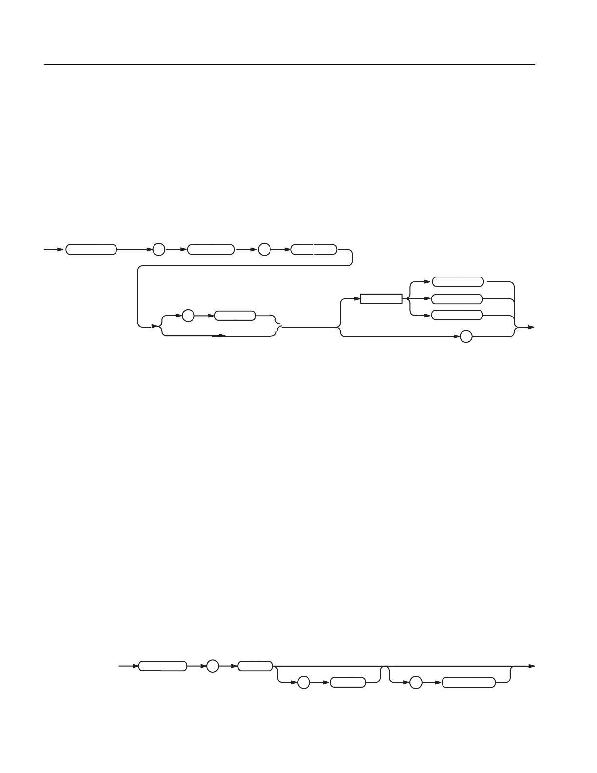
Command Descriptions
:AWGControl:ENHanced:SEQuence[:JMODe] (?)
This command selects the jump mode in the sequence of the enhanced mode.
AWGControl
Group
Syntax
: :
Arguments
AWG Control
:AWGcontrol:ENHanced:SEQuence[:JMODe] {LOGic | TABLe | SOFTware}
:AWGControl:ENHanced:SEQuence[:JMODe]?
ENHanced SEQuence
LOGic
<space>
:
JMODe
TABLe
SOFTware
?
LOGic The jump mo de is ”logic”.
TABLe The jump mode is ”table”.
SOFTware The jump mode is ”softwar e”.
At *RST, this value is set to TABLe.
Examples
:AWGControl:ENHanced:SEQuence SOFTware
sets the jump mode to software.
:AWGControl:EVENt[:LOGic][:IMMediate] (No Query Form)
This command generates a trigger event for the “logic jump” specified in the
sequence file. This has the same effect as pressing the FORCE EVENT button on
the front pa nel.
Group
Related Commands
Syntax
AWGControl
AWG Control
:AWGControl:RUN[:IMMediate], *TRG
:AWGControl:EVENt[:LOGic][:IMMediate]
:
EVENt
:
LOGic
:
IMMediate
2-30 AWG710&AWG710B Arbitrary Waveform Generator Programmer Manual
Page 61

Command Descriptions
Arguments
Examples
None
:AWGControl:EVENt:LOGic:IMMediate
generates a trigger event for the “logic jump”.
:AWGControl:EVENt:SOFTware[:IMMediate] (No Query Form)
This command jumps to a specified line in a sequence file. To enable this
command, a sequence fi le must be l oade d and so ft ware jump mode must be set in
the sequence file.
This command will return a “Settings confli ct” error (code:-221 ) when any of t hese
conditions are present:
1) The waveform generator is not in Enhanced mode.
2) No sequence file is loaded.
3) The Jump Mode setting of the sequence file is not Software.
It also will return a “D ata out of ran ge” error (c ode:- 222) if the <lin e> ar gument is
less than or equal to zero, or greater than the number of steps of the loade d
sequence file.
Group
Related Commands
Syntax
AWGControl
Arguments
Examples
AWG Control
None
:AWGControl:EVENt:SOFTware[:IMMediate] <line>
:
EVENt SOFTware IMMediate
::
<space>
<line>
<line>::=<NR1> is the line number to be jumped to in the sequence file.
:AWGControl:EVENt:SOFTware:IMMediate 10
jumps to line 10 in the sequence file.
AWG710&AWG710B Arbitrary Waveform Generator Programmer Manual 2-31
Page 62

Command Descriptions
:AWGControl:EVENt:TABLe[:IMMediate] (No Query Form)
This command generates a trigger event for the “table jump” specified in the
sequence file when a jump mode of sequence (ENHanced mode) is a Table.
Group
Related Commands
Syntax
Arguments
Examples
AWG Control
None
:AWGControl:EVENt:TABLe[:IMMediate]
AWGControl EVENt
:
None
:AWGControl:EVENt:TABLe:IMMediate
generates a trigger event for the “table jump ”.
:AWGControl:FG:FREQuency[:CW|:FIXed] (?)
This command adjusts the frequency of the function waveform.
This query returns the fr equency currently set.
CW (Continuous Wave) and FIXed are aliases, and have the same effect.
::
IMMediateTABLe
Group
Syntax
AWG Control
:AWGControl:FG:FREQuency[:CW|:FIXed] <numeric_value>
:AWGControl:FG:FREQuency[:CW|:FIXed]?
AWGContro l
:
:
FREQuency
FG
:
CW
FIXed
<space>
<NRf>
?
2-32 AWG710&AWG710B Arbitrary Waveform Generator Programmer Manual
Page 63
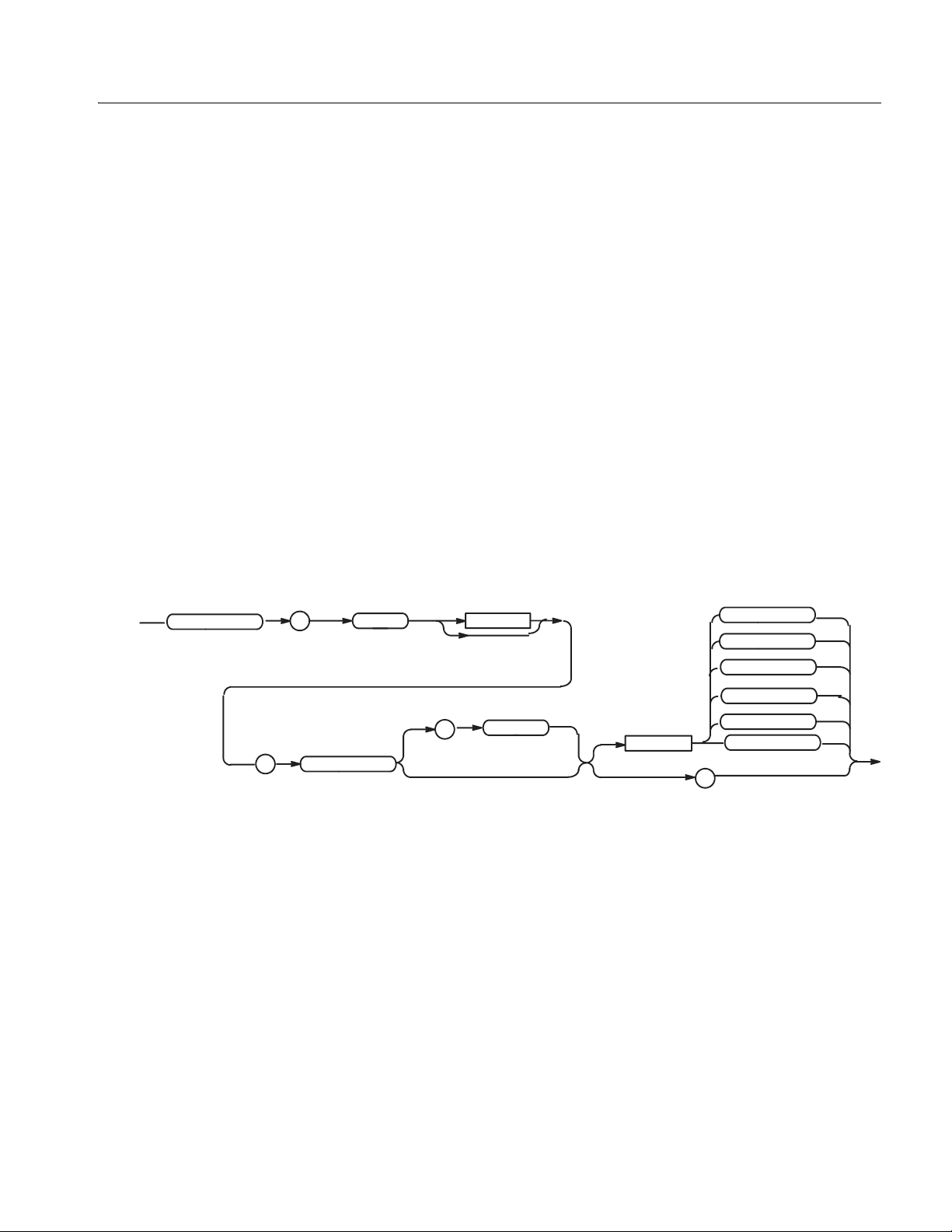
Command Descriptions
Arguments
<numeric_value> is the output waveform frequency. The range is 1Hz to 400
MHz.
At *RST, this value is set to 20 MHz.
Examples
:AWGControl:FG:FREQuency 10MHz
sets the frequency to 10 MHz.
:AWGControl:FG[1]:FUNCtion[:SHAPe] (?)
This command selects a standard function waveform (as opposed to a waveform
file).
This query returns the currently selected standard function waveform.
Group
Syntax
AWGControl
AWG Control
:AWGControl:FG[1]:FUNCtion[:SHAPe] <shape>
:AWGControl:FG[1]:FUNCtion[:SHAPe] ?
:
FG
1
SINusoid
TRIangle
SQUare
:
Arguments
Examples
:
FUNCtion
SHAPe
<space>
SINusoid selects a sine wave function waveform.
TRIangle selects a triangle function waveform.
SQUare selects a square wave function waveform.
RAMP selects a ramp function waveform.
PULSe selects a pulse function waveform.
DC selects a D C function wavefor m.
At *RST, this value is set to SINusoid
:AWGControl:FG1:FUNCtion RAMP
sets the standard function waveform to RAMP.
RAMP
PULSe
DC
?
AWG710&AWG710B Arbitrary Waveform Generator Programmer Manual 2-33
Page 64

Command Descriptions
:AWGControl:FG[1]:POLarity (?)
This command sets polarity of the funct ion waveform.
This query returns polarity currently set.
Group
Syntax
AWGControl
Arguments
AWG Control
:AWGControl:FG[1]:POLarity {POSitive | NEGative}
:AWGControl:FG[1]:POLarity?
:
:
FG
POLarity
1
<space>
?
POSitive sets waveform to positive polarity.
NEGative sets waveform to negative polarity.
At *RST, this value is set to POSitive.
POSitive
NEGative
Examples
:AWGControl:FG1:POLarity POSitive
sets the polarity to positive.
2-34 AWG710&AWG710B Arbitrary Waveform Generator Programmer Manual
Page 65

:AWGControl:FG[1]:PULSe:DCYCle (?)
This command sets the duty cycle of the pulse waveform.
This query returns the duty cycle of the pulse waveform.
Command Descriptions
AWGControl
Group
Syntax
:
:
Arguments
AWG Control
:AWGControl:FG[1]:PULSe:DCYCle <numeric_value>
:AWGControl:FG[1]:PULSe:DCYCle?
FG
1
DCYClePULSe
:
<space>
?
<numeric_value> is the duty cycle. The range is 0.1 to 99.9%.
Step:
Frequency Step(%)
1.000Hz to 4.000MHz 0.1
4.001MHz to 20.00MHz 0.5
20.01MHz to 40.00MHz 1
40.01MHz to 80.00MHz 2
80.01MHz to 100.0MHz 2.5
100.1MHz to 160.0MHz 4
160.1MHz to 200.0MHz 5
200.1MHz to 400.0MHz 10
<NRf>
At *RST, this value is set as 10.0.
Examples
:AWGControl:FG1:PULSe:DCYCle 20
sets the duty cycle to 20%.
AWG710&AWG710B Arbitrary Waveform Generator Programmer Manual 2-35
Page 66

Command Descriptions
:AWGControl:FG[:STATe] (?)
This command turns the FG(Function Generation) mode on or off.
This query returns status indicating whether the waveform generator is set to the
function generator mode.
AWGControl
Group
Syntax
:
Arguments
AWG Control
AWGControl:FG[:STATe] <boolean>
AWGControl:FG[:STATe]?
:
FG
<boolean> ::={ OFF | ON | <NRf> }
OFF or 0 sets the FG mode to OFF .
ON or 1 sets the FG mode to ON.
STATe
<space>
OFF
ON
<NRf>
?
At *RST, this value is set to OFF.
Examples
:AWGControl:FG ON
sets the FG mode to ON.
2-36 AWG710&AWG710B Arbitrary Waveform Generator Programmer Manual
Page 67
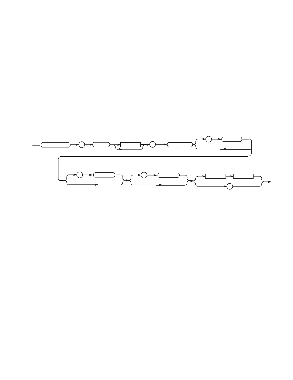
:AWGControl:FG[1]:VOLTage[:LEVel][:IMMediate][:AMPLitude] (?)
This command adjusts peak-to-peak voltage of the function waveform.
This query returns peak-to-peak voltag e currently set.
Command Descriptions
AWGControl
Group
Syntax
:
:
Arguments
AWG Control
:AWGControl:FG[1]:VOLTage[:LEVel][:IMMediate][:AMPLitude]
<numeric_value>
:AWGControl:FG[1]:VOLTage[:LEVel][:IMMediate][:AMPLitude]?
LEVel
<NRf>
?
FG 1
IMMediate
:
:
:
VOLTage
AMPLitude
<space>
<numeric_value> is the amplitude of the waveform. The Step is 1mV.
The range is 0.020Vpp to 2.000Vpp
(In the case of Option02: 0.5Vpp to 1.0Vpp)
At *RST, this value is set to 1.0.
Examples
:AWGControl:FG1:VOLTage 2.0
sets the amplitude to 2.000Vpp.
AWG710&AWG710B Arbitrary Waveform Generator Programmer Manual 2-37
Page 68

Command Descriptions
:AWGControl:FG[1]:VOLTage[:LEVel][:IMMediate]:OFFSet (?) (except option02)
This comma nd adjusts offset voltage of the function waveform.
This query returns offset voltage currently set.
AWGControl
Group
Syntax
:
:
Arguments
AWG Control
A:WGControl:FG[1]:VOLTage[:LEVel][:IMMediate]:OFFSet
<numeric_value>
:AWGControl:FG[1]:VOLTage[:LEVel][:IMMediate]:OFFSet?
FG
IMMediate
:
1
:
:
OFFSet
VOLTage
<space>
LEVel
<numeric_value> is the offset of the waveform. The Step is 1mV.
The range is -0.500V to +0.500V
At *RST, this value is set to 0.0.
<NRf>
?
Examples
:AWGControl:FG1:VOLTage:OFFSet 0.1
sets the offset to 0.1V.
:AWGControl:MIX[:STATe] (?)
This command turns the Waveform Mixing mode on or off.
This query returns status indicating whether the waveform generator is set to the
Waveform Mixing mode.
ThecommandwhichsetsupeachparameterinWaveformMixingmode
isnotsupported.
Group
Syntax
2-38 AWG710&AWG710B Arbitrary Waveform Generator Programmer Manual
AWG Control
:AWGControl:MIX[:STATe] <boolean>
:AWGControl:MIX[:STATe]?
Page 69
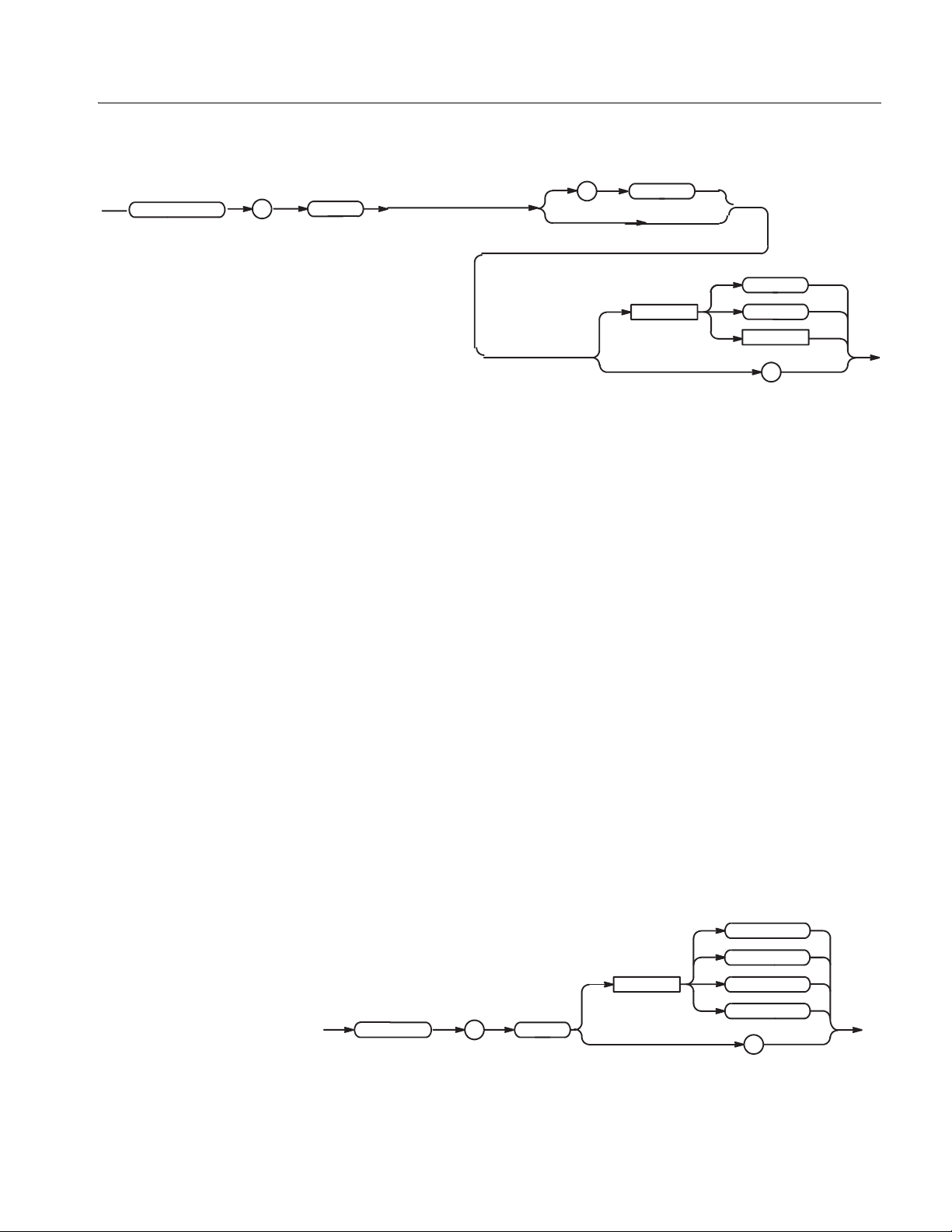
Command Descriptions
AWGControl
:
Arguments
Examples
:
MIX
STATe
<space>
<boolean> ::={ OFF | ON | <NRf> }
OFF or 0 sets the Waveform Mixing mode to OFF .
ON or 1 sets the Waveform Mixing mode to ON.
At *RST, this value is set to OFF.
:AWGControl:MIX ON
sets the Waveform Mixing mode to ON.
OFF
ON
<NRf>
?
:AWGControl:RMODe (?)
This command selects the mode used to output waveforms or sequences.
Group
Related Commands
Syntax
AWG Control
:AWGControl:RUN[:IMMediate], AWGControl:STOP[:IMMediate],
[:SOURce[1]]:FUNCtion:USER, *TRG
:AWGControl:RMODe { CONTinuous | TRIGgered | GATed | ENHanced }
:AWGControl:RMODe?
AWGControl
CONTinuous
TRIGgered
<space>
:
RMODe
GATed
ENHanced
?
AWG710&AWG710B Arbitrary Waveform Generator Programmer Manual 2-39
Page 70

Command Descriptions
Arguments
You can select the modes listed in Table 2-18.
Table 2-18: Selecting run modes
Arguments Arguments
CONTinuous
TRIGgered
GATed
ENHanced
Sets the continuous mode, which continuously outputs the waveform. The
external trigger, including FORCE TRIGGER button and the corresponding
remote commands, have no effect.
Sets the triggered mode, which outputs one waveform cycle for each trigger.
Sets the gated mode, which continuously outputs the waveform or sequence
as long as the trigger remains enabled. The trigger remains effective as long
as any of the following events occur:
The FORCE TRIGGER button remains pressed
A valid external gate signal remains input
The TRIGger[:SEQuence][:IMMediate] or *TRG command has
been executed but an ABORt command has not yet been issued
Sets the enhanced mode, which outputs the waveform according to the
sequence file specified with the SOURce:FUNCtion:USER command. If the
sequence file is not loaded, this mode is the same as the triggered mode.
At *RST, this parameter is set to CONTinuous.
Examples
SOURce:FUNCtion:USER "SAMPLE1.SEQ";:AWGControl:RMODe ENHanced;RUN
outputs waveform according to the sequence file SAMPLE1.SEQ.
:AWGControl:RMODe?
can return the following response:
TRIG
:AWGControl:RSTate? (Query Only)
This command returns the current running status.
Group
Syntax
Arguments
AWG Control
:AWGControl:RSTate?
AWGControl
None
:
RSTate
?
2-40 AWG710&AWG710B Arbitrary Waveform Generator Programmer Manual
Page 71

Command Descriptions
Returns
Examples
<NR1>
0 The waveform generator is stopped.
1 The waveform generator is waiting for a trigger.
2 The waveform generator is running.
:AWGControl:RSTate?
can return the following response:
1
:AWGControl:RUN[:IMMediate] (No Query Form)
This command init iates t he output of a w av efo rm or a se quence. This has the same
effect as manually pressing the RUN button on the front panel.
Group
Related Commands
Syntax
AWG Control
:AWGControl:STOP[:IMMediate], *TRG
:AWGControl:RUN[:IMMediate]
Arguments
Examples
AWGControl
None
:AWGControl:RUN[:IMMediate]
initiates the output of a waveform or a sequence.
: :
RUN
IMMediate
AWG710&AWG710B Arbitrary Waveform Generator Programmer Manual 2-41
Page 72

Command Descriptions
:AWGControl:SREStore (No Query Form)
This comma nd resets the default settings of a spec ified file.
Group
Related Commands
Syntax
AWGControl SREStore
Arguments
Examples
AWG Control
:AWGControl:SSAVe, :MMEMory:CDIRectory, :MMEMory:MSIS:
:AWGControl:SREStore <file_name>[,<msus>]
:
<file_name>::=<string> specifies the file to restore the settings.
<msus> (mass storage unit specifier)::=<string> is the media on which
the file exists:
MAIN Internal hard disk drive
FLOPpy Internal floppy disk drive
NET1, NET2, or NET3 Network drive 1, 2, or 3 (specified with
:AWGControl:SREStore "SAMPLE1.SET","FLOPpy"
resets the default settings of the file SAMPLE1.SET on the floppy disk.
<space>
the SYSTem:COMMunicate:LAN commands)
<file_name>
,
<msus>
:AWGControl:SSAVe (No Query Form)
This comma nd stores the current settings to a sp ecified file.
Group
Related Commands
Syntax
2-42 AWG710&AWG710B Arbitrary Waveform Generator Programmer Manual
AWG Control
:AWGControl:SREStore, :MMEMory:CDIRectory, :MMEMory:MSIS
:AWGControl:SSAVe <file_name>[,<msus>]
Page 73

Command Descriptions
AWGControl
Arguments
:
SSAVe
<file_name>::=<string> specifies the file to store the settings.
<space>
<msus> (mass storage unit specifier)::=<string> is the media on which
the file exists:
MAIN Internal hard disk driv e
FLOPpy Internal floppy disk drive
NET1, NET2, or NET3 Network drive 1, 2, or 3 (specified with
the SYSTem:COMMunicate:LAN commands)
Examples
:AWGControl:SSAVe "SAMPLE1.SET","FLOPpy"
stores the current settings to the file SAMPLE1.SET on the floppy disk.
:AWGControl:STOP[:IMMediate] (No Query Form)
This command terminates waveform output. When the mode is not set to
continuous, it also rese ts the sequence po inter to output the wav eform from the top
of the sequence with the next trigger event.
<file_name>
,
<msus>
Group
Related Commands
Syntax
Arguments
Examples
AWG Control
:AWGControl:RUN[:IMMediate], *TRG
:AWGControl:STOP[:IMMediate]
AWGControl
: :
STOP IMMediate
None
:AWGControl:STOP[:IMMediate]
stops the output of a waveform.
AWG710&AWG710B Arbitrary Waveform Generator Programmer Manual 2-43
Page 74

Command Descriptions
:AWGControl:SYNChronous:ADDRess (?) (AWG710B only)
This command sets the IP address of the slave AWG710B for the Synchronous
Operation.
Group
Syntax
AWG Control
:AWGControl:SYNChronous:ADDRess <ip_address>
:AWGControl:SYNChronous:ADDRess?
AWGContro l
Arguments
<space>
:
SYNChronous
:
ADDRess
<ip_address>::=<string> is the IP address of the slave AWG710B.
<ip_address>
?
*RST has no effect on the value.
Examples
:AWGControl:SYNChronous:ADDRess "192.150.30.54"
sets the IP address of the slave AWG710B to “192.150.30.54”.
:AWGControl:SYNChronous:CALibration (No Query Form) (AWG710B only)
This command executes the Trigger Timing Calibration for the Synchronous
Operation.
Group
Syntax
Examples
AWG Control
:AWGControl:SYNChronous:CALibration
AWGControl
:
SYNChronous
:AWGControl:SYNChronous:CALibratioin
:
CALibration
executes the Trigger Timing Calibration.
2-44 AWG710&AWG710B Arbitrary Waveform Generator Programmer Manual
Page 75

:AWGControl:SYNChronous:CONNect (?) (AWG710B only)
This command establishes a Master-Slave relati onship of two waveform
generators in the Synchronous Operation.
This query returns status indicating whethe r t he communication of two wavef orm
generators has been established.
Command Descriptions
AWGControl
Group
Syntax
:
Arguments
AWG Control
:AWGControl:SYNChronous:CONNect <boolean>
:AWGControl:SYNChronous:CONNect?
<space>
SYNChronous
:
CONNect
<boolean> ::={ OFF | ON | <NRf> }
OFF or 0 sets the Waveform Mixing mode to OFF .
ON or 1 sets the Waveform Mixing mode to ON.
At *RST, this value is set to OFF.
OFF
ON
<NRf>
?
Examples
:AWGControl:MIX ON
sets the Waveform Mixing mode to ON.
AWG710&AWG710B Arbitrary Waveform Generator Programmer Manual 2-45
Page 76

Command Descriptions
:AWGControl:SYNChronous:MASTer[:STATe] (?) (AWG710B only)
This command turns the Synchronous Operation mode on or off, and sets the
waveform generator as a master
AWGControl
Arguments
Group
Syntax
AWG Control
:AWGControl:SYNChronous:MASTer[:STATe] <boolean>
:AWGControl:SYNChronous:MASTer[:STATe]?
STATe
MASTer
<space>
OFF
ON
<NRf>
?
:
SYNChronous
:
:
<boolean> ::={ OFF | ON | 0 | 1 }
OFF or 0 sets the Synchronous Operation mode to OFF and an operation mode
turns to normal operaion.
ON or 1 set s t he Sync hronous Operation mode t o ON and the wavefor m generator
as a master instrument.
At *RST, this value is set to OFF.
Examples
:AWGControl:SYNChronous:MASTer[:STATe] ON
sets the Synchronous Operation to ON as a master.
2-46 AWG710&AWG710B Arbitrary Waveform Generator Programmer Manual
Page 77
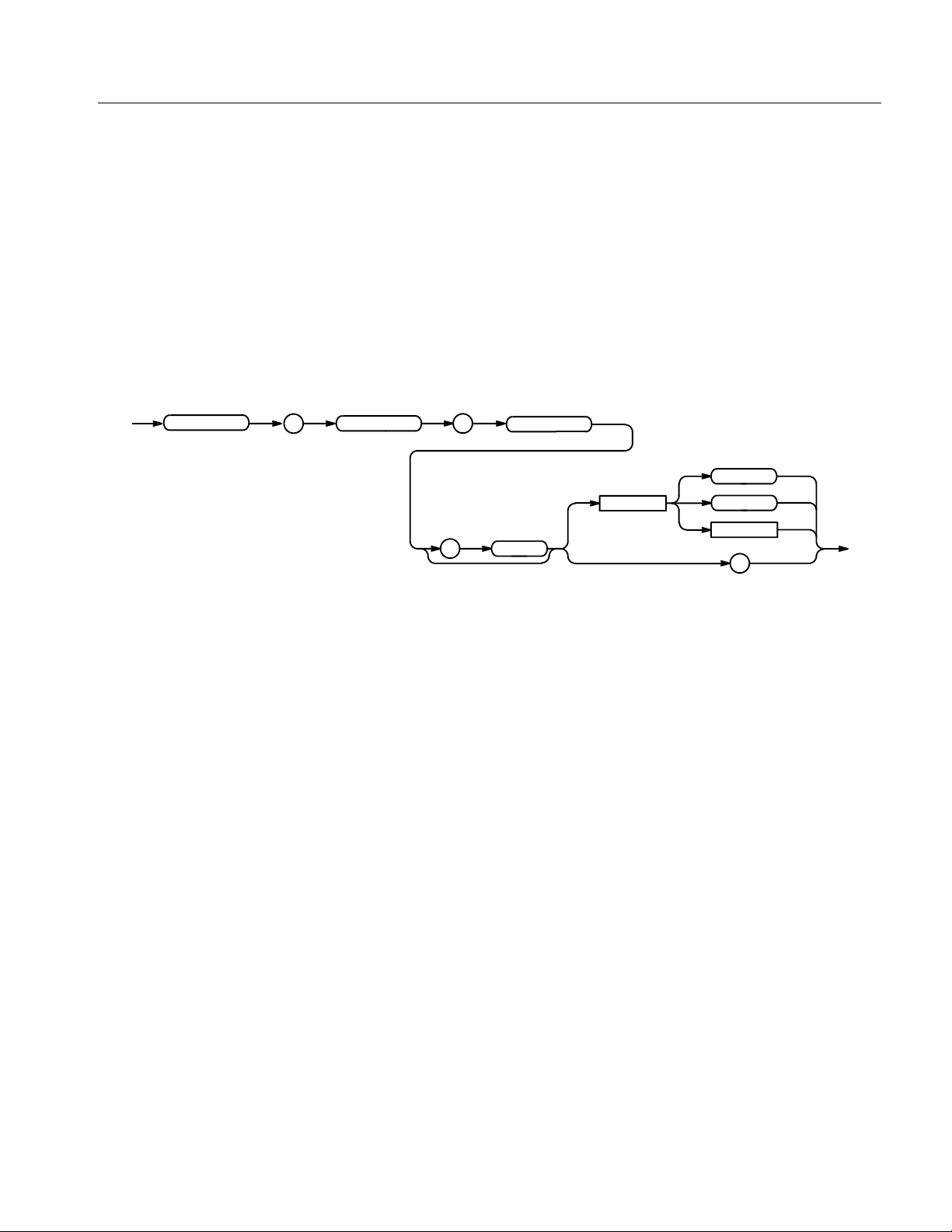
:AWGControl:SYNChronous:SLAVe[:STATe] (?) (AWG710B only)
This command turns the Synchronous Operation mode on or off, and sets the
waveform generator as a slave.
Command Descriptions
AWGControl
Arguments
Group
Syntax
AWG Control
:AWGControl:SYNChronous:SLAVe[:STATe] <boolean>
:AWGControl:SYNChronous:SLAVe[:STATe]?
:
SYNChronous
:
:
STATe
SLAVe
<space>
OFF
ON
<NRf>
?
<boolean> ::={ OFF | ON | 0 | 1 }
OFF or 0 sets the Synchronous Operation mode to OFF and an operation mode
turns to normal operaion.
ON or 1 set s t he Sync hronous Operation mode t o ON and the wavefor m generator
as a slave instrument.
At *RST, this value is set to OFF.
Examples
:AWGControl:SYNChronous:SLAVe[:STATe] ON
sets the Synchronous Operation to ON as a slave.
AWG710&AWG710B Arbitrary Waveform Generator Programmer Manual 2-47
Page 78

Command Descriptions
*CAL? (Query Only)
The *CAL? query performs an internal cali bration and ret urns a status th at indicates
whether or not the waveform generator completed the calibration successfully. If
an error is detected during calibration, execution immediately stops, and an error
code is returned. This query performs the same function as the
CALibration[:ALL]? query.
NOTE. A period of time is required to complete the internal calibration. During
this time, the waveform generator does not respond to any commands or queries
issued.
Group
Related Commands
Syntax
Arguments
Returns
Examples
:CALibration[:ALL] (?)
Calibration
:CALibration[:ALL]?
*CAL?
*CAL
None
<NR1>
0 Terminated without error.
-340 Calibration failed.
*CAL?
performs an internal calibration an d returns the results. For exam ple, the query
might return 0, which indicates the calibration terminated without any errors.
?
The :CALibration[:ALL] command performs a full calibration of the waveform
generator.
The :CALibration[:ALL]? query perfor ms a full calib rati on and r esponds with a
<NR1> indicating the success of the calibration. This query has the same function
as the *CAL? query.
2-48 AWG710&AWG710B Arbitrary Waveform Generator Programmer Manual
Page 79

Command Descriptions
If an error is detected during calibration, a message is queued in the error/event
queue, and the error code “-340” is returned.
NOTE. A period of time is required to complete the internal calibration. During
this time, the waveform generator does not respond to any commands or queries
issued.
Group
Related Commands
Syntax
Arguments
Returns
Examples
Calibration
*CAL?
:CALibration[:ALL]
:CALibration[:ALL]?
CALibration
:
None
<NR1>
0 Terminated without error.
-340 Calibration failed.
:CALibration[:ALL]
performs a full calibration.
ALL
?
:CALibration[:ALL]?
performs a full calibration and returns the results. For example, it might return 0,
which indicates the calibration terminated without any errors.
AWG710&AWG710B Arbitrary Waveform Generator Programmer Manual 2-49
Page 80

Command Descriptions
*CLS (No Query Form)
This command clears all the event registers and queues, used by the waveform
generator status and event reporting system. For more details, refer to the, Status
and Events section.
Group
Syntax
Arguments
Examples
Status
*CLS
*CLS
None
*CLS
clears all the event registers and queues.
:DIAGnostic:DATA? (Query Only)
This command returns the results of a self–test.
Group
Related Commands
Syntax
Diagnostic
:DIAGnostic[:IMMediate], :DIAGnostic:SELect
:DIAGnostic:DATA?
DIAGnostic
Arguments
Returns
Examples
2-50 AWG710&AWG710B Arbitrary Waveform Generator Programmer Manual
None
<NR1>
0 Terminated without error.
-330 Self–test failed.
:DIAGnostic:DATA?
might return 0.
:
DAT A
?
Page 81

:DIAGnostic[:IMMediate] (?)
The :DIAGnostic[:IMMediate] command executes the self–test routine(s)
selected by the :DIAGnostic:SELect command. The query :DIAGnostic
[:IMMediate]? executes the routine(s) and returns the results.
If an error is detected during execution, the routine that detected the error
terminates. If all of the s elf–test routines are selected, self–testing con t inues with
execution of the next self–test routine.
Command Descriptions
Group
Related Commands
Syntax
Arguments
Returns
Examples
Diagnostic
:DIAGnostic:SELect, :DIAGnostic:DATA?
:DIAGnostic[:IMMediate]
:DIAGnostic[:IMMediate]?
:
DIAGnostic
IMMediate
?
None
<NR1>
0 Terminated without error.
-330 Self–test failed.
:DIAGnostic:SELect ALL;IMMediate?
executes all of the self–test routines. After all self–test routines finish, the results
of the self–tests are returned.
AWG710&AWG710B Arbitrary Waveform Generator Programmer Manual 2-51
Page 82

Command Descriptions
:DIAGnostic:SELect (?)
This command selects the self–te st routi n e( s) .
Group
Related Commands
Syntax
Diagnostic
:DIAGnostic[:IMMediate]
:DIAGnostic:SELect { ALL | OUTPut | RMODe | ROSCillator
| SMEMory | SYSTem | WMEMory }
:DIAGnostic:SELect?
ALL
OUTPut
RMODe
ROSCillator
SMEMory
DIAGnostic
<space>
:
SELect
SYSTem
WMEMory
?
Arguments
Examples
You can select the following self–test routines:
Table 2-19: Self–test routines
Argument Description
ALL
OUTput
RMODe
ROSCillator
SMEMory
SYSTem
WMEMory
Checks all routines that follow
Checks the analog output unit
Checks the control unit
Checks the reference oscillator unit
Checks the sequence memory
Checks the system unit, such as the system memory
Checks the waveform memory
At *RST, this parameter is set to ALL.
:DIAGnostic:SELect WMEMory;IMMediate
executes the waveform memory self–test routine.
2-52 AWG710&AWG710B Arbitrary Waveform Generator Programmer Manual
Page 83
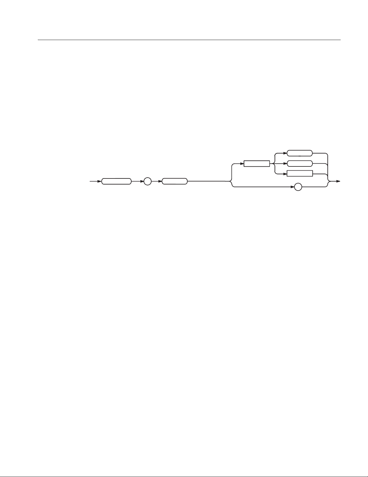
:DISPlay:ENABle (?)
Command Descriptions
This command controls ON/OFF of the display.
Group
Syntax
DISPlay
Arguments
Examples
Display
:DISPlay:ENABle <boolean>
:DISPlay:ENABle?
:
ENABle
<boolean> ::={ OFF | ON | 0 | 1 }
OFF or 0 sets OFF the display.
ON or 1 sets ON the display.
At *RST, this value is set to OFF.
:DISPlay:ENABle ON
sets ON the display.
<space>
OFF
ON
<NR1>
?
AWG710&AWG710B Arbitrary Waveform Generator Programmer Manual 2-53
Page 84

Command Descriptions
:DISPlay:HILight:COLor (?)
This command controls the HILight color.
*ESE (?)
Group
Syntax
Display
:DISPlay:HILight:COLor <NR1>
:DISPlay:HILight:COLor?
DISPlay HILight
Arguments
:
<NR1> is the color number. The range is 0 to 7.
At *RST, this value is set to 0.
Returns
Examples
<NR1> indicates the number of color.
:DISPlay:HILight:COLor 1
sets the number 1 color.
<space>
:
COLor
<NR1>
?
The *ESE command sets the bit s of the ESER ( Eve nt Stat us Enable Regi ster ) used
in the status and events reporting system of the waveform generator. The *ESE?
query returns the contents of the ESER. Refer to the Status and Events for more
information about the ESER.
Group
Related Commands
Syntax
Status
*CLS, *ESR?, *PSC, *SRE, *STB?
*ESE <bit_value>
*ESE?
*ESE
<space>
<bit_value>
?
2-54 AWG710&AWG710B Arbitrary Waveform Generator Programmer Manual
Page 85

Command Descriptions
Arguments
Examples
*ESR? (Query Only)
<bit_value>::=<NR1>
where <NR1> is a decima l integer in the range 0 to 255. The bi nary bits of the ESER
are set according to this value.
The power–on default f or ESER is 0 if *PSC is 1. If *PSC is 0, the ESER ma intains
its value through a power cycle.
*ESE 177
sets the ESER to 177 (binary 10110001 ), which sets the PON, CME, EXE and OPC
bits.
*ESE?
might return 176, which indicates that the ESER contains the binary number
10110000.
This command returns the contents of the Standard Event Status Register (SESR)
used in the status and events reporting system in the waveform generator. *ESR?
also clears the SESR (since reading the SESR clears it). Refer to Section 3 Status
and Events for more informat ion.
Group
Related Commands
Syntax
Returns
Examples
Status
*CLS, *ESE?, *SRE, *STB?
*ESR?
*ESR
<NR1> indicates the content of the SESR in a decimal integer.
*ESR?
might return 181, which indicates that the SESR contains the binary number
10110101.
?
AWG710&AWG710B Arbitrary Waveform Generator Programmer Manual 2-55
Page 86

Command Descriptions
:HCOPy:DESTination (No Query Form)
This command sets the hardcopy destination. For the waveform generator, the
destination is always set to MMEMory (mass memory). This command is included
only for compatibility w ith the SCP I standard. T he destination file on the mass
memory device is specified by the :MMEMory:NAME command. For more
information about hardcopy, see Hardcopy Commands on page 2-18.
Group
Related Commands
Syntax
Arguments
Hardcopy
:MMEMory:NAME
:HCOPy:DESTination <data_handle>
<data_handle>::=<string>
where <string> is fixed to ”MMEMory” for the waveform generator.
Examples
:HCOPy:DESTination "MMEMory"
sets the hardcopy destination to a file specified with the MMEMory:NAME command.
:HCOPy:DEVice:COLor (?)
This command sets the hardcopy color mode.
Group
Hardcopy
HCOPy
:
DESTination
<space>
<data_handle>
Related Commands
Syntax
:HCOPy:DEVice:LANGuage
:HCOPy:DEVice:COLor { OFF | ON | <NRf> }
:HCOPy:DEVice:COLor?
OFF
HCOPy
Arguments
<space>
:
DEVice
:
COLor
OFF or <NRf>=0 sets the hardcopy color mode to OFF.
ON
<NR1>
?
ON or <NRf>≠0 sets the hardcopy color mode to ON.
2-56 AWG710&AWG710B Arbitrary Waveform Generator Programmer Manual
Page 87

At *RST, this value is set to OFF.
Command Descriptions
Returns
ON : when hardcopy color mode is set to ON.
OFFN : when hardc opy color mod e is set to OFF
Examples
:HCOPy:DEVice:COLor ON
sets the hardcopy color mode to ON.
:HCOPy:DEVice:LANGuage (?)
This command sets the hardcopy data format.
Group
Related Commands
Syntax
Hardcopy
:HCOPy:DEVice:COLor
:HCOPy:DEVice:LANGuage { BMP | TIFF }
:HCOPy:DEVice:LANGuage?
HCOPy
:
DEVice
:
LANGuage
BMP
<space>
Arguments
Examples
TIFF
?
BMP specifies the Windows bitmap file format.
TIFF specifies the TIFF format.
At *RST, the parameter is set to BMP.
:HCOPy:DEVice:LANGuage TIFF
specifies the TIFF data format for hardcop y.
AWG710&AWG710B Arbitrary Waveform Generator Programmer Manual 2-57
Page 88

Command Descriptions
:HCOPy[:IMMediate] (No Query Form)
This command immediately initiates hardcopy output according to the current
HCOPy setup parameters. F or the wavefo rm gene ra tor, this command is the same
as :HCOPy:SDUMp[:IMMediate]. For more information about hardcopy, see
Hardcopy Commands on page 2-18.
Group
Related Commands
Syntax
Arguments
Examples
Hardcopy
:HCOPy:DESTination, :HCOPy:SDUMp[:IMMediate]
:HCOPy[:IMMediate]
HCOPy
:
IMMediate
None
:HCOPy:IMMediate
starts hardcopy output.
:HCOPy:SDUMp[:IMMediate] (No Query Form)
This command initiates a screen dump of the entire screen. For the waveform
generator, this is the same as the :HCOPy[:IMMediate] command. For more
information about hardcopy, see Hardcopy Commands on page 2-18.
Group
Syntax
Arguments
Examples
Hardcopy
:HCOPy:SDUMp[:IMMediate]
HCOPy
SDUMp
::
IMMediate
None
:MMEMory:NAME "SAMPLE1.BMP";:HCOPy:SDUMp:IMMediate
prints the entire screen to the file SAMPLE1.BMP.
2-58 AWG710&AWG710B Arbitrary Waveform Generator Programmer Manual
Page 89

*IDN? (Query Only)
Command Descriptions
This command returns identification information for the waveform generator.
Group
Syntax
Arguments
Returns
Examples
System
*IDN?
*IDN
None
<manufacturer>, <model>, <serial_number>, <firmware_level>
where
<manufacturer>::=SONY/TEK (AWG710), TEKTRONIX (AWG710B)
<model>::= AWG710 (AWG710), AWG710B (AWG710B)
<serial_number>::=0
<firmware_level>::=SCPI:99.0 OS:x.y USR:x.y
*IDN?
might return SONY/TEK,AWG710B,0,SCPI:99.0 OS:1.2 USR:4.0
?
AWG710&AWG710B Arbitrary Waveform Generator Programmer Manual 2-59
Page 90

Command Descriptions
:MMEMory:CATalog? (Query Only)
This command returns in formation about the current contents an d state of the mass
storage me dia.
Group
Related Commands
Syntax
Arguments
Returns
Mass Memory
:MEMory:CDIRectory, :MMEMory:MSIS
:MMEMory:CATalog?[ <msus>]
MMEMory
:
CATalog
?
<space>
<msus>
<msus> (mass storage unit specifier)::=<string> is one of the following:
MAIN The internal hard disk drive
FLOPpy The internal floppy disk drive
NET1, NET2, or NET3 The network drive 1, 2, or 3 (specified with the
SYSTem:COMMunicate:LAN commands)
<NR1>,<NR1>[,<file_name>,<file_type>,<file_size>]...
where:
The first <NR1> is the total amount of storage currently used, in
bytes.
For the network drives, <NR1>=0.
The second <NR1> is the total amount of storage available.
For the network drives, <NR1>=0.
<file_name>,<file_type>,<file_size>::=<string>
where
<file_name> is the exact name of a file,
<file_type> is DIR for directory, otherwise it is blank, and
<file_size> is the size of the file, in bytes.
Examples
:MMEMory:CATalog? "MAIN"
might return the following response:
484672,3878652,"SAMPLE1.WFM,2948"
2-60 AWG710&AWG710B Arbitrary Waveform Generator Programmer Manual
Page 91

:MMEMory:CDIRectory (?)
This command changes t he default directory for a mass memory file s ystem. The
default mass storage device is selected by :MMEMory:MSIS command.
Command Descriptions
Group
Related Commands
Syntax
Arguments
Examples
Mass Memory
:MMEMory:CDIRectory, :MMEMory:MSIS
:MMEMory:CDIRectory [<directory_name>]
:MMEMory:CDIRectory?
MMEMory
:
CDIRectory
<space>
<directory_name>
?
<directory_name>::=<string>
is the default directory for a mass mem ory file system.
If you do not specify a parameter, the directory is set to the *RST value.
At *RST, this parameter is set to the roo t.
:MMEMory:CDIRectory "/AWG/WORK0"
changes the default directory to /AWG/WORK0.
:MMEMory:CLOSe (No Query Form)
This command closes the file specified in the MMEMory:NAME command. This
command is included only for compatibility with the SCPI standard and may not
be used.
Group
Related Commands
Syntax
Arguments
Examples
AWG710&AWG710B Arbitrary Waveform Generator Programmer Manual 2-61
Mass Memory
:MMEMory:NAME, :MMEMory:OPEN
:MMEMory:CLOSe
MMEMory
:
CLOSe
None
:MMEMory:NAME "SAMPLE1.WFM";CLOSe
closes the file SAMPLE1.WFM.
Page 92

Command Descriptions
:MMEMory:COPY (No Query Form)
This command copies an existing file to a new file. An error is generated if the
source file does not exist.
Group
Related Commands
Syntax
MMEMory
Arguments
Mass Memory
:MMEMory:CDIRectory, :MMEMory:DELete, :MMEMory:MSIS
:MMEMory:COPY <file_source>,<file_destination>
:
COPY
<space>
<file_source>
,
<file_destination>
<file_source>::=<file_name>[,<msus>]
<file_destination>::=<file_name>[,<msus>]
where:
<file_name>::=<string> is the source or destination file name.
<msus> (mass storage unit specifier)::=<string> is the media on which
the file exists:
MAIN Internal hard disk drive
FLOPpy Internal floppy disk drive
NET1, NET2, or NET3 Network drive 1, 2, or 3 (specified with
the SYSTem:COMMunicate:LAN commands)
Examples
:MMEMory:COPY "FILE1.WFM","MAIN","FILE2.WFM","FLOPpy"
copies the file FILE1.WFM on the waveform generator hard disk to the file
FILE2.WFM on the floppy disk.
:MMEMory:DATA (?)
This command loads blo ck data into the f i le on the default mass stora ge de vic e, or
returns the contents of the file.
Group
Related Commands
Syntax
2-62 AWG710&AWG710B Arbitrary Waveform Generator Programmer Manual
Mass Memory
:MMEMory:CDIRectory, :MMEMory:MSIS
:MMEMory:DATA <file_name>,<data>
:MMEMory:DATA <file_name>?
Page 93

Command Descriptions
MMEMory
Arguments
:
<file_name>::=<string> specifies the file to be loaded with data.
DATA
<data> is in 488.2 block format.
Examples
:MMEMory:DATA "FILE1",#41024xxxxx...
loads data into the file FILE1.
:MMEMory:DELete (No Query Form)
This command removes a file from the specified mass storage device.
Group
Related Commands
Syntax
Mass Memory
:MMEMory:CDIRectory, MMEMory:MSIS
:MMEMory:DELete <file_name>[,<msus>]
<space> <file_name> <data>
,
?
MMEMory
Arguments
Examples
:
DELete
<space>
<file_name> <msus>
,
<file_name>::=<string> specifies the file to be removed.
<msus> (mass storage unit specifier)::=<string> is the media on which
the file exists:
MAIN Internal hard disk driv e
FLOPpy Internal floppy disk drive
NET1, NET2, or NET3 Network drive 1, 2, or 3 (specified with
the SYSTem:COMMunicate:LAN commands)
:MMEMory:DELete "FILE1.WFM","FLOPpy"
removes the file FILE 1.WFM on the floppy disk.
AWG710&AWG710B Arbitrary Waveform Generator Programmer Manual 2-63
Page 94

Command Descriptions
:MMEMory:FEED (?)
This command sets the data handle to be used to feed data into the file specified by
:MMEMory:NAME. For the waveform generator, the data handle is fixed to HCOPy.
This command is included onl y for compatibilit y with the SCPI stand ard, and may
not be used (refer to Hardcopy Commands on page 2-18).
Group
Related Commands
Syntax
Arguments
Examples
Mass Memory
MMEMory:NAME
:MMEMory:FEED <data_handle>
MMEMory:FEED?
MMEMory
<space>
:
FEED
<data_handle>
?
<data_handle>::=<string> fo r the w a vefo rm gener ator, the data handle is fi xed
to HCOPy.
At *RST, this parameter is set to ” HCOP”.
:MMEMory:FEED "HCOPy"
sets the data handle.
2-64 AWG710&AWG710B Arbitrary Waveform Generator Programmer Manual
Page 95

:MMEMory:INITialize (No Query Form)
This command initializes a specif i ed mass sto rag e media. In thi s application, you
can initialize the internal hard disk or floppy disk.
NOTE. The initializing process erases all information that is already on the disk.
This command is a “Quick Format” command, which cann ot format MA C f ormat,
other OS format and damaged disk.
Command Descriptions
Group
Related Commands
Syntax
MMEMory
:
Arguments
Mass Memory
:MMEMory:MSIS
:MMEMory:INITialize[ <msus>[,DOS[,<NR1>]]]
INITialize
<space>
<msus>
,
,
DOS
<NR1>
<msus> (mass storage unit specifier)::=<string> is the media containing
the specified mass storage:{ "MAIN" | "FLOPpy" }
where MAIN means the internal hard disk, and FLOPpy means the floppy disk.
The media is initialized in DOS format.
<NR1> is ignored in this application (It usually specifies media–dependent
information).
When you specify MAIN, this command returns the instrument settings to the
factory defaults, except for the communication parameters (see Appendix E:
Factory Initialization Settings).
Examples
:MME Mory:INITialize "FLOPpy"
initializes a floppy disk in DOS forma t .
AWG710&AWG710B Arbitrary Waveform Generator Programmer Manual 2-65
Page 96

Command Descriptions
:MMEMory:MDIRectory (No Query Form)
This command creates a directory on the specified mass storage unit.
Group
Related Commands
Syntax
MMEMory
Arguments
Examples
Mass Memory
:MMEMory:CDIRectory, :MMEMory:MSIS
:MMEMory:MDIRectory <directory_name>[,<msus>]
:
MDIRectory
<space>
<directory_name>
,
<msus>
<directory_name>::=<string> specifies a new dir ectory.
<msus> (mass storage unit specifier)::=<string> is the media on which
you make the directory:
MAIN Internal hard disk drive
FLOPpy Internal floppy disk drive
NET1, NET2, or NET3 Network drive 1, 2, or 3 (specified with
the SYSTem:COMMunicate:LAN commands)
:MMEMory:MDIRectory "WAVEFORM","FLOPpy"
makes the directory “WAVEFORM” on the floppy disk.
2-66 AWG710&AWG710B Arbitrary Waveform Generator Programmer Manual
Page 97

:MMEMory:MOVE (No Query Form)
This command moves an existing file to another file name. If the source file does
not exist, an error occurs.
Command Descriptions
Group
Related Commands
Syntax
MMEMory
Arguments
Mass Memory
:MMEMory:CDIRectory, :MMEMory:COPY, :MMEMory:DELete, :MMEMory:MSIS
:MMEMory:MOVE <file_source>,<file_destination>
:
MOVE
<space>
<file_source>
,
<file_destination>
<file_source>, <file_destination>
::=<file_name>[,<msus>]
where:
<file_name>::=<string> is the source or destination file name.
<msus> (mass storage unit specifier)::=<string> is the media on which
the file exists:
MAIN Internal hard disk driv e
FLOPpy Internal floppy disk drive
NET1, NET2, or NET3 Network drive 1, 2, or 3 (specified with
the SYSTem:COMMunicate:LAN commands)
Examples
:MMEMory:MOVE "FILE1.WFM","MAIN","FILE2.WFM","FLOPpy"
moves the file FILE1.WMF on the waveform gene ra tor har d dis k to FI LE2.W FM
on the floppy disk.
AWG710&AWG710B Arbitrary Waveform Generator Programmer Manual 2-67
Page 98

Command Descriptions
:MMEMory:MSIS (?)
The “Mass Storage IS” command selects a default mass storage device that is used
by all MMEMory commands except INITialize.
Group
Related Commands
Syntax
Arguments
Mass Memory
All MMEMory commands except INITialize.
:MMEMory:MSIS[ <msus>]
:MMEMory:MSIS?
<space>
MMEMory
<msus>(Mass Storage Unit Specifier)::=<string> specifies a default mass
storage device.
MAIN Internal hard disk drive
FLOPpy Internal floppy disk drive
NET1, NET2, or NET3 Network drive 1, 2, or 3 (specified with
At *RST, this parameter is set to MAIN.
:
MSIS
the SYSTem:COMMunicate:LAN commands)
<msus>
?
Examples
:MMEMory:MSIS "FLOPpy"
selects the floppy disk drive as the default mass storage device.
:MMEMory:NAME (?)
This command specif ies th e name of the f ile spec if ication us ed by MMEMory:OPEN
or CLOSe commands.
Group
Related Commands
Syntax
2-68 AWG710&AWG710B Arbitrary Waveform Generator Programmer Manual
Mass Memory
:MMEMory:CLOSe, :MMEMory:OPEN
:MMEMory:NAME <file_name>[,<msus>]
:MMEMory:NAME?
Page 99

<space>
<file_name>
Command Descriptions
<msus>
,
MMEMory
Arguments
:
NAME
<file_name>::=<string> is the name of the file to be opened or closed.
<msus> (mass storage unit specifier)::=<string> is the media on which
the file exists:
MAIN Internal hard disk driv e
FLOPpy Internal floppy disk drive
NET1, NET2, or NET3 Network drive 1, 2, or 3 (specified with
At *RST, this parameter is set to ”HARDCOPY”.
Examples
:MMEMory:NAME "SAMPLE1.WFM","NET1";OPEN
opens the file SAMPLE1.WFM on the network drive 1.
:MMEMory:OPEN (No Query Form)
This command opens the file specified in the MMEMory:NAME command. This
command is included only for compatibility, and may not be used.
?
the SYSTem:COMMunicate:LAN commands)
Group
Related Commands
Syntax
Arguments
Examples
Mass Memory
:MMEMory:CDIRectory, :MMEMory:CLOSe, :MMEMory:MSIS, :MMEMory:NAME
:MMEMory:OPEN
MMEMory
:
OPEN
None
:MMEMory:NAME "SAMPLE1.WFM","NET1";OPEN
opens the file SAMPLE1.WFM on the network drive 1.
AWG710&AWG710B Arbitrary Waveform Generator Programmer Manual 2-69
Page 100

Command Descriptions
*OPC (?)
Operation complete command (query). Use this command between two other
commands to ensure complet ion of the first command before processing the second
command.
In this applicatio n, all commands are designed t o be ex ecuted in t he order in whic h
they are sent from the external controller. The *OPC (?) command is included to
ensure compliance with the SCPI standard. You do not need to use this command.
Refer to page 3-6 about the OPC bit of SESR (Standard Event Status Register).
Group
Related Commands
Syntax
Arguments
Returns
*OPT? (Query Only)
Group
Synchronization
*WAI
*OPC
*OPC?
*OPC
?
None
<NR1>=1 when all pending operations are finished.
This comma nd returns the implemented options of the waveform generator.
System
Syntax
Arguments
Returns
2-70 AWG710&AWG710B Arbitrary Waveform Generator Programmer Manual
*OPT?
*OPT
None
<opt>[,<opt>[,<opt>[,<opt>]]]
where:
?
 Loading...