

Page 1

User Manual
AWG710 & AWG710B
4 GS/s / 4.2 GS/s Arbitrary Waveform Generator
071-1413-01
This document supports firmware version 4.00 and above.
www.tektronix.com
Page 2

Copyright © Tektronix Ja pan, Ltd. All rights reserved.
Copyright © Tektronix, Inc. All rights reserved.
Tektronix products are covered by U.S. and foreign patents, issued and pending. Information in this publication
supercedes that in all previously published material. Specifications and price change privileges reserved.
Tektronix, Inc., P.O. Box 500, Beaverton, OR 97077
TEKTRONIX and TEK are registered trademarks of Tektronix, Inc.
Page 3

WARRANTY
Tektronix warrants that the products that it manufactures and sells will be free from defects in materials and
workmanship for a period of on e (1) year f rom the da te of shi pment. If a pr oduct pr ov es defecti v e during this wa rranty
period, Tektronix, at its option, either will repair the defective product without charge for parts and labor, or will
provide a replacement in exchange for the defective product.
In order to obtain service under this warranty, Customer must notify Tektronix of the defect before the expiration of
the warranty period and make s uitable arrangements fo r the perform ance of service. Cu stomer shall be respo nsible for
packaging and shipping the defective product to the service center designated by Tektronix, with shipping charges
prepaid. T ektronix shall pay for the return of the product to Customer if the shipment is to a location within the country
in which the T e ktronix serv ice center is lo cated. Custo mer shall be respo nsible for payi ng all shippi ng char ges, duties,
taxes, and any other charges for products returned to any other locations.
This warranty shall not apply to any defect, failure or damage caused by improper use or improper or inadequate
maintenance and care. Tektronix shall not be obligated to furnish service under this warranty a) to repair damage
resulting from attempts by personnel other than Tektronix representatives to install, repair or service the product; b) to
repair damage resulting from improper use or connection to incompatible equipment; c) to repair any damage or
malfunction caused by the use of non -T ektronix su pplies; or d) to s ervice a product that has been modified or inte grated
with other products when the effect of s uch modif ication or integration increases the time or diff iculty of servicing the
product.
THIS WARRANTY IS GIVEN BY TEKTRONIX IN LIEU OF ANY OTHER WARRANTIES, EXPRESS OR
IMPLIED. TEKTRONIX AND ITS VENDORS DISCLAIM ANY IMPLIED WARRANTIES OF
MERCHANT ABILITY OR FITNESS FOR A P AR TICULAR PURPOSE. TEKTRONIX’ RESPONSIBILITY
TO REPAIR OR REPLACE DEFECTIVE PRODUCTS IS THE SOLE AND EXCLUSIVE REMEDY
PROVIDED TO THE CUSTOMER FOR BREACH OF THIS WARRANTY. TEKTRONIX AND ITS
VENDORS WILL NOT BE LIABLE FOR ANY INDIRECT, SPECIAL, INCIDENTAL, OR
CONSEQUENTIAL DAMAGES IRRESPECTIVE OF WHETHER TEKTRONIX OR THE VENDOR HAS
ADVANCE NOTICE OF THE POSSIBILITY OF SUCH DAMAGES.
Page 4

Page 5

Table of Contents
Table of Contents . . . . . . . . . . . . . . . . . . . . . . . . . . . . . . . . . . . . . . . . . . . . . . . . . . . . . . i
General Safety Summary . . . . . . . . . . . . . . . . . . . . . . . . . . . . . . . . . . . . . . . . . . . . . xvii
Preface . . . . . . . . . . . . . . . . . . . . . . . . . . . . . . . . . . . . . . . . . . . . . . . . . . . . . . . . . . . . xix
Manual Structure . . . . . . . . . . . . . . . . . . . . . . . . . . . . . . . . . . . . . . . . . . . . . . . . . . . . . xix
Conventions . . . . . . . . . . . . . . . . . . . . . . . . . . . . . . . . . . . . . . . . . . . . . . . . . . . . . . . . . . xx
Related Manuals. . . . . . . . . . . . . . . . . . . . . . . . . . . . . . . . . . . . . . . . . . . . . . . . . . . . . . xxi
Contacting Tektronix . . . . . . . . . . . . . . . . . . . . . . . . . . . . . . . . . . . . . . . . . . . . . . . . . . xxi
Getting Started
Getting Started . . . . . . . . . . . . . . . . . . . . . . . . . . . . . . . . . . . . . . . . . . . . . . . . . . . . . 1-1
Product Description . . . . . . . . . . . . . . . . . . . . . . . . . . . . . . . . . . . . . . . . . . . . . . . . . . . 1-1
Incoming Inspection. . . . . . . . . . . . . . . . . . . . . . . . . . . . . . . . . . . . . . . . . . . . . . . . . . . 1-4
Power Cord Options. . . . . . . . . . . . . . . . . . . . . . . . . . . . . . . . . . . . . . . . . . . . . . . . . . . 1-5
Language Options . . . . . . . . . . . . . . . . . . . . . . . . . . . . . . . . . . . . . . . . . . . . . . . . . . . . 1-5
Accessories. . . . . . . . . . . . . . . . . . . . . . . . . . . . . . . . . . . . . . . . . . . . . . . . . . . . . . . . . . 1-6
Options. . . . . . . . . . . . . . . . . . . . . . . . . . . . . . . . . . . . . . . . . . . . . . . . . . . . . . . . . . . . . 1-8
Installation . . . . . . . . . . . . . . . . . . . . . . . . . . . . . . . . . . . . . . . . . . . . . . . . . . . . . . . . . 1-10
Repackaging for Shipment. . . . . . . . . . . . . . . . . . . . . . . . . . . . . . . . . . . . . . . . . . . . . 1-16
Operating Basics
Reference
Operating Basics . . . . . . . . . . . . . . . . . . . . . . . . . . . . . . . . . . . . . . . . . . . . . . . . . . . . 2-1
Controls and Connectors . . . . . . . . . . . . . . . . . . . . . . . . . . . . . . . . . . . . . . . . . . . . . . . 2-1
Menu Operations . . . . . . . . . . . . . . . . . . . . . . . . . . . . . . . . . . . . . . . . . . . . . . . . . . . . . 2-8
Numeric Input . . . . . . . . . . . . . . . . . . . . . . . . . . . . . . . . . . . . . . . . . . . . . . . . . . . . . . 2-12
Text Input. . . . . . . . . . . . . . . . . . . . . . . . . . . . . . . . . . . . . . . . . . . . . . . . . . . . . . . . . . 2-14
Shortcut Controls . . . . . . . . . . . . . . . . . . . . . . . . . . . . . . . . . . . . . . . . . . . . . . . . . . . . 2-15
File Management . . . . . . . . . . . . . . . . . . . . . . . . . . . . . . . . . . . . . . . . . . . . . . . . . . . . 2-17
Quick View. . . . . . . . . . . . . . . . . . . . . . . . . . . . . . . . . . . . . . . . . . . . . . . . . . . . . . . . . 2-24
Editor Overview. . . . . . . . . . . . . . . . . . . . . . . . . . . . . . . . . . . . . . . . . . . . . . . . . . . . . 2-26
Setup Overview . . . . . . . . . . . . . . . . . . . . . . . . . . . . . . . . . . . . . . . . . . . . . . . . . . . . . 2-34
Theory of Operation. . . . . . . . . . . . . . . . . . . . . . . . . . . . . . . . . . . . . . . . . . . . . . . . . . 2-41
Signal Edit Process. . . . . . . . . . . . . . . . . . . . . . . . . . . . . . . . . . . . . . . . . . . . . . . . . . . 2-46
Tutorials . . . . . . . . . . . . . . . . . . . . . . . . . . . . . . . . . . . . . . . . . . . . . . . . . . . . . . . . . . 2-49
Tutorial 1: Instrument Setup . . . . . . . . . . . . . . . . . . . . . . . . . . . . . . . . . . . . . . . . . . . 2-51
Tutorial 2: Loading and Outputting a Sample Waveform . . . . . . . . . . . . . . . . . . . . . 2-53
Tutorial 3: Creating and Editing Standard Function Waveforms. . . . . . . . . . . . . . . . 2-56
Tutorial 4: Editing a Waveform Using Quick Editor . . . . . . . . . . . . . . . . . . . . . . . . . 2-63
Tutorial 5: Using the Equation Editor . . . . . . . . . . . . . . . . . . . . . . . . . . . . . . . . . . . . 2-67
Tutorial 6: Creating and Running Waveform Sequences. . . . . . . . . . . . . . . . . . . . . . 2-70
Reference . . . . . . . . . . . . . . . . . . . . . . . . . . . . . . . . . . . . . . . . . . . . . . . . . . . . . . . . . . 3-1
Overview . . . . . . . . . . . . . . . . . . . . . . . . . . . . . . . . . . . . . . . . . . . . . . . . . . . . . . . . . . . 3-1
Menu Structures . . . . . . . . . . . . . . . . . . . . . . . . . . . . . . . . . . . . . . . . . . . . . . . . . . . . 3-3
AWG710&AWG710B Arbitrary Waveform Generator User Manual i
Page 6

Table of Contents
Setup Menu Hierarchy . . . . . . . . . . . . . . . . . . . . . . . . . . . . . . . . . . . . . . . . . . . . . . . . . 3-4
EDIT Menu Hierarchy . . . . . . . . . . . . . . . . . . . . . . . . . . . . . . . . . . . . . . . . . . . . . . . . 3-13
APPL Menu Hierarchy . . . . . . . . . . . . . . . . . . . . . . . . . . . . . . . . . . . . . . . . . . . . . . . . 3-26
Utility Menu Hierarchy. . . . . . . . . . . . . . . . . . . . . . . . . . . . . . . . . . . . . . . . . . . . . . . . 3-30
The Setup Menu Screen . . . . . . . . . . . . . . . . . . . . . . . . . . . . . . . . . . . . . . . . . . . . . . 3-33
Setup Menu Screen Elements . . . . . . . . . . . . . . . . . . . . . . . . . . . . . . . . . . . . . . . . . . . 3-33
The Waveform/Sequence Menu . . . . . . . . . . . . . . . . . . . . . . . . . . . . . . . . . . . . . . . . . 3-36
The Vertical Menu. . . . . . . . . . . . . . . . . . . . . . . . . . . . . . . . . . . . . . . . . . . . . . . . . . . . 3-38
The Horizontal Menu . . . . . . . . . . . . . . . . . . . . . . . . . . . . . . . . . . . . . . . . . . . . . . . . . 3-40
The Run Mode Menu . . . . . . . . . . . . . . . . . . . . . . . . . . . . . . . . . . . . . . . . . . . . . . . . . 3-44
The Trigger Menu. . . . . . . . . . . . . . . . . . . . . . . . . . . . . . . . . . . . . . . . . . . . . . . . . . . . 3-46
The Save/Restore Menu . . . . . . . . . . . . . . . . . . . . . . . . . . . . . . . . . . . . . . . . . . . . . . . 3-48
The Extended Operation Menu. . . . . . . . . . . . . . . . . . . . . . . . . . . . . . . . . . . . . . . . . . 3-50
Waveform, Pattern and Sequence Waveform Output . . . . . . . . . . . . . . . . . . . . . . . . . 3-51
The Graphical Waveform Editor . . . . . . . . . . . . . . . . . . . . . . . . . . . . . . . . . . . . . . 3-55
Editor Screen Elements. . . . . . . . . . . . . . . . . . . . . . . . . . . . . . . . . . . . . . . . . . . . . . . . 3-55
The File Menu. . . . . . . . . . . . . . . . . . . . . . . . . . . . . . . . . . . . . . . . . . . . . . . . . . . . . . . 3-58
The Operation Menu. . . . . . . . . . . . . . . . . . . . . . . . . . . . . . . . . . . . . . . . . . . . . . . . . . 3-59
The Tools Menu. . . . . . . . . . . . . . . . . . . . . . . . . . . . . . . . . . . . . . . . . . . . . . . . . . . . . . 3-72
The Zoom/Pan Menu. . . . . . . . . . . . . . . . . . . . . . . . . . . . . . . . . . . . . . . . . . . . . . . . . . 3-81
The Window Menu . . . . . . . . . . . . . . . . . . . . . . . . . . . . . . . . . . . . . . . . . . . . . . . . . . . 3-82
The Settings Menu . . . . . . . . . . . . . . . . . . . . . . . . . . . . . . . . . . . . . . . . . . . . . . . . . . . 3-82
The Pattern Editor . . . . . . . . . . . . . . . . . . . . . . . . . . . . . . . . . . . . . . . . . . . . . . . . . . 3-85
About Waveform and Pattern Files. . . . . . . . . . . . . . . . . . . . . . . . . . . . . . . . . . . . . . . 3-85
Starting the Pattern Editor. . . . . . . . . . . . . . . . . . . . . . . . . . . . . . . . . . . . . . . . . . . . . . 3-86
The File Menu. . . . . . . . . . . . . . . . . . . . . . . . . . . . . . . . . . . . . . . . . . . . . . . . . . . . . . . 3-87
The Operation Menu. . . . . . . . . . . . . . . . . . . . . . . . . . . . . . . . . . . . . . . . . . . . . . . . . . 3-87
The Tools Menu. . . . . . . . . . . . . . . . . . . . . . . . . . . . . . . . . . . . . . . . . . . . . . . . . . . . . . 3-87
The Zoom/Pan Menu. . . . . . . . . . . . . . . . . . . . . . . . . . . . . . . . . . . . . . . . . . . . . . . . . . 3-91
The Window Menu . . . . . . . . . . . . . . . . . . . . . . . . . . . . . . . . . . . . . . . . . . . . . . . . . . . 3-91
The Settings Menu . . . . . . . . . . . . . . . . . . . . . . . . . . . . . . . . . . . . . . . . . . . . . . . . . . . 3-91
The Undo! Command . . . . . . . . . . . . . . . . . . . . . . . . . . . . . . . . . . . . . . . . . . . . . . . . . 3-91
Selecting Data Bits to Edit . . . . . . . . . . . . . . . . . . . . . . . . . . . . . . . . . . . . . . . . . . . . . 3-92
Defining Edit Area . . . . . . . . . . . . . . . . . . . . . . . . . . . . . . . . . . . . . . . . . . . . . . . . . . . 3-93
Creating a Pattern . . . . . . . . . . . . . . . . . . . . . . . . . . . . . . . . . . . . . . . . . . . . . . . . . . . . 3-94
Creating Standard Patterns . . . . . . . . . . . . . . . . . . . . . . . . . . . . . . . . . . . . . . . . . . . . . 3-95
Inserting Data From Files . . . . . . . . . . . . . . . . . . . . . . . . . . . . . . . . . . . . . . . . . . . . . . 3-96
Set Pattern... . . . . . . . . . . . . . . . . . . . . . . . . . . . . . . . . . . . . . . . . . . . . . . . . . . . . . . . . 3-96
Quick Editing . . . . . . . . . . . . . . . . . . . . . . . . . . . . . . . . . . . . . . . . . . . . . . . . . . . . . . 3-99
Screen Display. . . . . . . . . . . . . . . . . . . . . . . . . . . . . . . . . . . . . . . . . . . . . . . . . . . . . . . 3-99
Quick Edit Mode. . . . . . . . . . . . . . . . . . . . . . . . . . . . . . . . . . . . . . . . . . . . . . . . . . . . 3-100
Quick Edit Mechanism . . . . . . . . . . . . . . . . . . . . . . . . . . . . . . . . . . . . . . . . . . . . . . . 3-100
About Smoothing . . . . . . . . . . . . . . . . . . . . . . . . . . . . . . . . . . . . . . . . . . . . . . . . . . . 3-101
Quick Controls . . . . . . . . . . . . . . . . . . . . . . . . . . . . . . . . . . . . . . . . . . . . . . . . . . . . . 3-101
Starting Quick Edit . . . . . . . . . . . . . . . . . . . . . . . . . . . . . . . . . . . . . . . . . . . . . . . . . . 3-102
Exiting Quick Edit. . . . . . . . . . . . . . . . . . . . . . . . . . . . . . . . . . . . . . . . . . . . . . . . . . . 3-103
Setting Parameters. . . . . . . . . . . . . . . . . . . . . . . . . . . . . . . . . . . . . . . . . . . . . . . . . . . 3-103
Moving the Cursor . . . . . . . . . . . . . . . . . . . . . . . . . . . . . . . . . . . . . . . . . . . . . . . . . . 3-104
Renewing Edit Buffer . . . . . . . . . . . . . . . . . . . . . . . . . . . . . . . . . . . . . . . . . . . . . . . . 3-104
About Undo. . . . . . . . . . . . . . . . . . . . . . . . . . . . . . . . . . . . . . . . . . . . . . . . . . . . . . . . 3-104
ii AWG710&AWG710B Arbitrary Waveform Generator User Manual
Page 7

Table of Contents
The Table Editor . . . . . . . . . . . . . . . . . . . . . . . . . . . . . . . . . . . . . . . . . . . . . . . . . . 3-105
Opening The Table Editor . . . . . . . . . . . . . . . . . . . . . . . . . . . . . . . . . . . . . . . . . . . . 3-105
Editing The Table Data . . . . . . . . . . . . . . . . . . . . . . . . . . . . . . . . . . . . . . . . . . . . . . 3-106
The Equation Editor . . . . . . . . . . . . . . . . . . . . . . . . . . . . . . . . . . . . . . . . . . . . . . . 3-109
Starting the Equation Editor. . . . . . . . . . . . . . . . . . . . . . . . . . . . . . . . . . . . . . . . . . . 3-110
Using the Equation Editor . . . . . . . . . . . . . . . . . . . . . . . . . . . . . . . . . . . . . . . . . . . . 3-111
Entering Keywords and Functions. . . . . . . . . . . . . . . . . . . . . . . . . . . . . . . . . . . . . . 3-114
Compiling Equations . . . . . . . . . . . . . . . . . . . . . . . . . . . . . . . . . . . . . . . . . . . . . . . . 3-115
The Sequence Editor . . . . . . . . . . . . . . . . . . . . . . . . . . . . . . . . . . . . . . . . . . . . . . . 3-117
Starting the Sequence Editor . . . . . . . . . . . . . . . . . . . . . . . . . . . . . . . . . . . . . . . . . . 3-117
Sequence Table Editing . . . . . . . . . . . . . . . . . . . . . . . . . . . . . . . . . . . . . . . . . . . . . . 3-120
Sequence Table Fields . . . . . . . . . . . . . . . . . . . . . . . . . . . . . . . . . . . . . . . . . . . . . . . 3-122
The APPL Menu . . . . . . . . . . . . . . . . . . . . . . . . . . . . . . . . . . . . . . . . . . . . . . . . . . 3-131
Disk Application . . . . . . . . . . . . . . . . . . . . . . . . . . . . . . . . . . . . . . . . . . . . . . . . . . . 3-131
Network Application . . . . . . . . . . . . . . . . . . . . . . . . . . . . . . . . . . . . . . . . . . . . . . . . 3-140
Jitter Composer Application . . . . . . . . . . . . . . . . . . . . . . . . . . . . . . . . . . . . . . . . . . 3-147
The UTILITY Window . . . . . . . . . . . . . . . . . . . . . . . . . . . . . . . . . . . . . . . . . . . . . 3-155
External Keyboards . . . . . . . . . . . . . . . . . . . . . . . . . . . . . . . . . . . . . . . . . . . . . . . . . 3-155
Setting General Purpose Knob Direction. . . . . . . . . . . . . . . . . . . . . . . . . . . . . . . . . 3-156
Formatting a Floppy Disk . . . . . . . . . . . . . . . . . . . . . . . . . . . . . . . . . . . . . . . . . . . . 3-157
Displaying Disk Usage. . . . . . . . . . . . . . . . . . . . . . . . . . . . . . . . . . . . . . . . . . . . . . . 3-157
Screen Display Enable/Disable . . . . . . . . . . . . . . . . . . . . . . . . . . . . . . . . . . . . . . . . 3-158
Focused Color . . . . . . . . . . . . . . . . . . . . . . . . . . . . . . . . . . . . . . . . . . . . . . . . . . . . . 3-158
Displaying Instrument Status. . . . . . . . . . . . . . . . . . . . . . . . . . . . . . . . . . . . . . . . . . 3-158
Internal Clock (Date and Time) . . . . . . . . . . . . . . . . . . . . . . . . . . . . . . . . . . . . . . . . 3-159
Resetting the Instrument . . . . . . . . . . . . . . . . . . . . . . . . . . . . . . . . . . . . . . . . . . . . . 3-159
Connecting to a GPIB Network. . . . . . . . . . . . . . . . . . . . . . . . . . . . . . . . . . . . . . . . 3-160
Ethernet Networking . . . . . . . . . . . . . . . . . . . . . . . . . . . . . . . . . . . . . . . . . . . . . . . . 3-162
Hardcopy . . . . . . . . . . . . . . . . . . . . . . . . . . . . . . . . . . . . . . . . . . . . . . . . . . . . . . . . . 3-170
Calibration and Diagnostics. . . . . . . . . . . . . . . . . . . . . . . . . . . . . . . . . . . . . . . . . . . 3-172
Upgrading the System Software . . . . . . . . . . . . . . . . . . . . . . . . . . . . . . . . . . . . . . . 3-179
Capturing Waveforms . . . . . . . . . . . . . . . . . . . . . . . . . . . . . . . . . . . . . . . . . . . . . . 3-181
Possible Instruments . . . . . . . . . . . . . . . . . . . . . . . . . . . . . . . . . . . . . . . . . . . . . . . . 3-181
Basic Concept on Communication for Capturing . . . . . . . . . . . . . . . . . . . . . . . . . . 3-181
Procedures for Capturing Waveforms . . . . . . . . . . . . . . . . . . . . . . . . . . . . . . . . . . . 3-182
About Transferred Files. . . . . . . . . . . . . . . . . . . . . . . . . . . . . . . . . . . . . . . . . . . . . . 3-184
Waveform Programming Language . . . . . . . . . . . . . . . . . . . . . . . . . . . . . . . . . . 3-185
Command Syntax. . . . . . . . . . . . . . . . . . . . . . . . . . . . . . . . . . . . . . . . . . . . . . . . . . . 3-185
User–Defined Variables . . . . . . . . . . . . . . . . . . . . . . . . . . . . . . . . . . . . . . . . . . . . . . 3-186
Waveform Files . . . . . . . . . . . . . . . . . . . . . . . . . . . . . . . . . . . . . . . . . . . . . . . . . . . . 3-187
Command Descriptions . . . . . . . . . . . . . . . . . . . . . . . . . . . . . . . . . . . . . . . . . . . . 3-189
Bpf( ) . . . . . . . . . . . . . . . . . . . . . . . . . . . . . . . . . . . . . . . . . . . . . . . . . . . . . . . . . . . . 3-189
Brf( ) . . . . . . . . . . . . . . . . . . . . . . . . . . . . . . . . . . . . . . . . . . . . . . . . . . . . . . . . . . . . 3-190
Code( ) . . . . . . . . . . . . . . . . . . . . . . . . . . . . . . . . . . . . . . . . . . . . . . . . . . . . . . . . . . . 3-191
Conv( ) . . . . . . . . . . . . . . . . . . . . . . . . . . . . . . . . . . . . . . . . . . . . . . . . . . . . . . . . . . . 3-191
Copy( ) . . . . . . . . . . . . . . . . . . . . . . . . . . . . . . . . . . . . . . . . . . . . . . . . . . . . . . . . . . 3-192
Corr( ) . . . . . . . . . . . . . . . . . . . . . . . . . . . . . . . . . . . . . . . . . . . . . . . . . . . . . . . . . . . 3-192
Data( ) . . . . . . . . . . . . . . . . . . . . . . . . . . . . . . . . . . . . . . . . . . . . . . . . . . . . . . . . . . . 3-193
Delete( ) . . . . . . . . . . . . . . . . . . . . . . . . . . . . . . . . . . . . . . . . . . . . . . . . . . . . . . . . . . 3-194
Diff( ) . . . . . . . . . . . . . . . . . . . . . . . . . . . . . . . . . . . . . . . . . . . . . . . . . . . . . . . . . . . 3-194
AWG710&AWG710B Arbitrary Waveform Generator User Manual iii
Page 8

Table of Contents
Expand( ) . . . . . . . . . . . . . . . . . . . . . . . . . . . . . . . . . . . . . . . . . . . . . . . . . . . . . . . . . 3-195
Extract( ) . . . . . . . . . . . . . . . . . . . . . . . . . . . . . . . . . . . . . . . . . . . . . . . . . . . . . . . . . . 3-195
For (Control Statement) . . . . . . . . . . . . . . . . . . . . . . . . . . . . . . . . . . . . . . . . . . . . . . 3-196
Hpf( ) . . . . . . . . . . . . . . . . . . . . . . . . . . . . . . . . . . . . . . . . . . . . . . . . . . . . . . . . . . . . 3-197
If (Control Statement) . . . . . . . . . . . . . . . . . . . . . . . . . . . . . . . . . . . . . . . . . . . . . . . 3-198
Integ( ) . . . . . . . . . . . . . . . . . . . . . . . . . . . . . . . . . . . . . . . . . . . . . . . . . . . . . . . . . . . 3-198
Join( ). . . . . . . . . . . . . . . . . . . . . . . . . . . . . . . . . . . . . . . . . . . . . . . . . . . . . . . . . . . . .3-199
Lpf( ) . . . . . . . . . . . . . . . . . . . . . . . . . . . . . . . . . . . . . . . . . . . . . . . . . . . . . . . . . . . . 3-199
Math Functions . . . . . . . . . . . . . . . . . . . . . . . . . . . . . . . . . . . . . . . . . . . . . . . . . . . . . 3-200
Math Operators . . . . . . . . . . . . . . . . . . . . . . . . . . . . . . . . . . . . . . . . . . . . . . . . . . . . . 3-202
Norm( ) . . . . . . . . . . . . . . . . . . . . . . . . . . . . . . . . . . . . . . . . . . . . . . . . . . . . . . . . . . . 3-203
Pn( ) . . . . . . . . . . . . . . . . . . . . . . . . . . . . . . . . . . . . . . . . . . . . . . . . . . . . . . . . . . . . .3-203
Rename( ) . . . . . . . . . . . . . . . . . . . . . . . . . . . . . . . . . . . . . . . . . . . . . . . . . . . . . . . . . 3-204
Variables (predefined) . . . . . . . . . . . . . . . . . . . . . . . . . . . . . . . . . . . . . . . . . . . . . . . 3-205
Write( ) . . . . . . . . . . . . . . . . . . . . . . . . . . . . . . . . . . . . . . . . . . . . . . . . . . . . . . . . . . . 3-206
Programming Examples . . . . . . . . . . . . . . . . . . . . . . . . . . . . . . . . . . . . . . . . . . . . 3-207
File Conversion . . . . . . . . . . . . . . . . . . . . . . . . . . . . . . . . . . . . . . . . . . . . . . . . . . . . 3-219
Import . . . . . . . . . . . . . . . . . . . . . . . . . . . . . . . . . . . . . . . . . . . . . . . . . . . . . . . . . . . . 3-219
Export . . . . . . . . . . . . . . . . . . . . . . . . . . . . . . . . . . . . . . . . . . . . . . . . . . . . . . . . . . . . 3-221
Convert between Waveform and Pattern. . . . . . . . . . . . . . . . . . . . . . . . . . . . . . . . . . 3-221
Executing File Conversion . . . . . . . . . . . . . . . . . . . . . . . . . . . . . . . . . . . . . . . . . . . . 3-222
File Management . . . . . . . . . . . . . . . . . . . . . . . . . . . . . . . . . . . . . . . . . . . . . . . . . . 3-225
Command Summary . . . . . . . . . . . . . . . . . . . . . . . . . . . . . . . . . . . . . . . . . . . . . . . . . 3-225
Path Name. . . . . . . . . . . . . . . . . . . . . . . . . . . . . . . . . . . . . . . . . . . . . . . . . . . . . . . . . 3-225
File Operations . . . . . . . . . . . . . . . . . . . . . . . . . . . . . . . . . . . . . . . . . . . . . . . . . . . . . 3-226
File Operation in Double Windows. . . . . . . . . . . . . . . . . . . . . . . . . . . . . . . . . . . . . . 3-230
FG Mode . . . . . . . . . . . . . . . . . . . . . . . . . . . . . . . . . . . . . . . . . . . . . . . . . . . . . . . . . 3-233
Change the generator mode. . . . . . . . . . . . . . . . . . . . . . . . . . . . . . . . . . . . . . . . . . . . 3-234
Parameters. . . . . . . . . . . . . . . . . . . . . . . . . . . . . . . . . . . . . . . . . . . . . . . . . . . . . . . . . 3-236
Waveform Mixing Mode . . . . . . . . . . . . . . . . . . . . . . . . . . . . . . . . . . . . . . . . . . . . 3-241
Change the generator mode. . . . . . . . . . . . . . . . . . . . . . . . . . . . . . . . . . . . . . . . . . . . 3-242
File... menu . . . . . . . . . . . . . . . . . . . . . . . . . . . . . . . . . . . . . . . . . . . . . . . . . . . . . . . . 3-243
Waveform Mixing parameters. . . . . . . . . . . . . . . . . . . . . . . . . . . . . . . . . . . . . . . . . . 3-245
Update . . . . . . . . . . . . . . . . . . . . . . . . . . . . . . . . . . . . . . . . . . . . . . . . . . . . . . . . . . . . 3-246
Save/Restore Setup . . . . . . . . . . . . . . . . . . . . . . . . . . . . . . . . . . . . . . . . . . . . . . . . . . 3-247
Operation Flow . . . . . . . . . . . . . . . . . . . . . . . . . . . . . . . . . . . . . . . . . . . . . . . . . . . . . 3-247
Synchronous Operation Mode (AWG710B only) . . . . . . . . . . . . . . . . . . . . . . . . 3-249
restrictions. . . . . . . . . . . . . . . . . . . . . . . . . . . . . . . . . . . . . . . . . . . . . . . . . . . . . . . . . 3-250
Connecting the cables . . . . . . . . . . . . . . . . . . . . . . . . . . . . . . . . . . . . . . . . . . . . . . . . 3-250
Change the generator mode. . . . . . . . . . . . . . . . . . . . . . . . . . . . . . . . . . . . . . . . . . . . 3-252
Setup screen. . . . . . . . . . . . . . . . . . . . . . . . . . . . . . . . . . . . . . . . . . . . . . . . . . . . . . . . 3-253
Setting a Slave IP address . . . . . . . . . . . . . . . . . . . . . . . . . . . . . . . . . . . . . . . . . . . . . 3-254
Testing the Network Connection. . . . . . . . . . . . . . . . . . . . . . . . . . . . . . . . . . . . . . . . 3-254
Connection with Slave. . . . . . . . . . . . . . . . . . . . . . . . . . . . . . . . . . . . . . . . . . . . . . . . 3-255
Error messages on connection. . . . . . . . . . . . . . . . . . . . . . . . . . . . . . . . . . . . . . . . . . 3-255
Trigger Timing Calibration . . . . . . . . . . . . . . . . . . . . . . . . . . . . . . . . . . . . . . . . . . . . 3-256
Save/Restore Setup . . . . . . . . . . . . . . . . . . . . . . . . . . . . . . . . . . . . . . . . . . . . . . . . . . 3-257
Operation Flow . . . . . . . . . . . . . . . . . . . . . . . . . . . . . . . . . . . . . . . . . . . . . . . . . . . . . 3-257
iv AWG710&AWG710B Arbitrary Waveform Generator User Manual
Page 9

Appendices
Table of Contents
Specifications (AWG710B) . . . . . . . . . . . . . . . . . . . . . . . . . . . . . . . . . . . . . . . . . . . . A-1
Electrical Specification . . . . . . . . . . . . . . . . . . . . . . . . . . . . . . . . . . . . . . . . . . . . . . . . A-2
Certification and Compliances. . . . . . . . . . . . . . . . . . . . . . . . . . . . . . . . . . . . . . . . . . A-25
Specifications (AWG710) . . . . . . . . . . . . . . . . . . . . . . . . . . . . . . . . . . . . . . . . . . . . A-27
Electrical Specification . . . . . . . . . . . . . . . . . . . . . . . . . . . . . . . . . . . . . . . . . . . . . . . A-28
Certification and Compliances. . . . . . . . . . . . . . . . . . . . . . . . . . . . . . . . . . . . . . . . . . A-40
Performance Verification (AWG710B) . . . . . . . . . . . . . . . . . . . . . . . . . . . . . . . . . . B-1
Conventions . . . . . . . . . . . . . . . . . . . . . . . . . . . . . . . . . . . . . . . . . . . . . . . . . . . . . . . . . B-1
Self Tests . . . . . . . . . . . . . . . . . . . . . . . . . . . . . . . . . . . . . . . . . . . . . . . . . . . . . . . . . . .B-2
Performance Tests . . . . . . . . . . . . . . . . . . . . . . . . . . . . . . . . . . . . . . . . . . . . . . . . . . . . B-6
Operating Mode Tests . . . . . . . . . . . . . . . . . . . . . . . . . . . . . . . . . . . . . . . . . . . . . . . . B-13
Amplitude and Offset Accuracy Tests (Normal Out), (except option 02) . . . . . . . . . B-19
Amplitude, Offset Accuracy and Rise Time Tests (Direct DA Out),
(except option 02). . . . . . . . . . . . . . . . . . . . . . . . . . . . . . . . . . . . . . . . . . . . . . . B-23
Amplitude, Offset Accuracy and Rise Time Tests (for option 02) . . . . . . . . . . . . . . B-27
Pulse Response Tests (Normal Out), (except option 02) . . . . . . . . . . . . . . . . . . . . . . B -31
Trigger Input Tests . . . . . . . . . . . . . . . . . . . . . . . . . . . . . . . . . . . . . . . . . . . . . . . . . . . B-33
Event Input and Enhanced Mode Tests . . . . . . . . . . . . . . . . . . . . . . . . . . . . . . . . . . . B-37
External Clock Input and VCO Out Output Tests . . . . . . . . . . . . . . . . . . . . . . . . . . . B-46
VCO OUT Output Frequency and 10 MHz Reference Input Tests . . . . . . . . . . . . . . B-48
Marker Output Tests. . . . . . . . . . . . . . . . . . . . . . . . . . . . . . . . . . . . . . . . . . . . . . . . . . B-50
Synchronous Operation Tests. . . . . . . . . . . . . . . . . . . . . . . . . . . . . . . . . . . . . . . . . . . B-52
Performance Verification (AWG710) . . . . . . . . . . . . . . . . . . . . . . . . . . . . . . . . . . . B-55
Conventions . . . . . . . . . . . . . . . . . . . . . . . . . . . . . . . . . . . . . . . . . . . . . . . . . . . . . . . . B-55
Self Tests . . . . . . . . . . . . . . . . . . . . . . . . . . . . . . . . . . . . . . . . . . . . . . . . . . . . . . . . . . B-56
Performance Tests . . . . . . . . . . . . . . . . . . . . . . . . . . . . . . . . . . . . . . . . . . . . . . . . . . . B-60
Operating Mode Tests . . . . . . . . . . . . . . . . . . . . . . . . . . . . . . . . . . . . . . . . . . . . . . . . B-66
Amplitude and Offset Accuracy Tests (Normal Out), (except option 02) . . . . . . . . . B-72
Amplitude, Offset Accuracy and Rise Time Tests (Direct DA Out),
(except option 02) . . . . . . . . . . . . . . . . . . . . . . . . . . . . . . . . . . . . . . . . . . . . . . . B-77
Amplitude, Offset Accuracy and Rise Time Tests (for option 02) . . . . . . . . . . . . . . B-81
Pulse Response Tests (Normal Out), (except option 02) . . . . . . . . . . . . . . . . . . . . . . B -85
Trigger Input Tests . . . . . . . . . . . . . . . . . . . . . . . . . . . . . . . . . . . . . . . . . . . . . . . . . . . B-87
Event Input and Enhanced Mode Tests . . . . . . . . . . . . . . . . . . . . . . . . . . . . . . . . . . . B-91
1/4 Clock Frequency and 10 MHz Reference Input Tests . . . . . . . . . . . . . . . . . . . . . B-98
Marker Output Tests. . . . . . . . . . . . . . . . . . . . . . . . . . . . . . . . . . . . . . . . . . . . . . . . . B-100
Inspection and Cleaning . . . . . . . . . . . . . . . . . . . . . . . . . . . . . . . . . . . . . . . . . . . . . . C-1
Sample Waveforms . . . . . . . . . . . . . . . . . . . . . . . . . . . . . . . . . . . . . . . . . . . . . . . . . . D-1
Waveform File Descriptions. . . . . . . . . . . . . . . . . . . . . . . . . . . . . . . . . . . . . . . . . . . . . D-2
File Transfer Interface Outline . . . . . . . . . . . . . . . . . . . . . . . . . . . . . . . . . . . . . . . . E-1
Miscellaneous . . . . . . . . . . . . . . . . . . . . . . . . . . . . . . . . . . . . . . . . . . . . . . . . . . . . . . . F-1
Sampling Theorem. . . . . . . . . . . . . . . . . . . . . . . . . . . . . . . . . . . . . . . . . . . . . . . . . . . . F -1
Differentiation . . . . . . . . . . . . . . . . . . . . . . . . . . . . . . . . . . . . . . . . . . . . . . . . . . . . . . . F-1
Integration . . . . . . . . . . . . . . . . . . . . . . . . . . . . . . . . . . . . . . . . . . . . . . . . . . . . . . . . . . F-3
Convolution . . . . . . . . . . . . . . . . . . . . . . . . . . . . . . . . . . . . . . . . . . . . . . . . . . . . . . . . . F-4
Correlation . . . . . . . . . . . . . . . . . . . . . . . . . . . . . . . . . . . . . . . . . . . . . . . . . . . . . . . . . . F-5
Code Conversion . . . . . . . . . . . . . . . . . . . . . . . . . . . . . . . . . . . . . . . . . . . . . . . . . . . . . F-7
Examples . . . . . . . . . . . . . . . . . . . . . . . . . . . . . . . . . . . . . . . . . . . . . . . . . . . . . . . . . . . F-8
AWG710&AWG710B Arbitrary Waveform Generator User Manual v
Page 10

Table of Contents
Index
Sequence File Text Format . . . . . . . . . . . . . . . . . . . . . . . . . . . . . . . . . . . . . . . . . . . G-1
Header . . . . . . . . . . . . . . . . . . . . . . . . . . . . . . . . . . . . . . . . . . . . . . . . . . . . . . . . . . . . . G-1
Line Descriptions . . . . . . . . . . . . . . . . . . . . . . . . . . . . . . . . . . . . . . . . . . . . . . . . . . . . G-1
Jump Settings . . . . . . . . . . . . . . . . . . . . . . . . . . . . . . . . . . . . . . . . . . . . . . . . . . . . . . . G-3
Examples. . . . . . . . . . . . . . . . . . . . . . . . . . . . . . . . . . . . . . . . . . . . . . . . . . . . . . . . . . . G-4
Index . . . . . . . . . . . . . . . . . . . . . . . . . . . . . . . . . . . . . . . . . . . . . . . . . . . . . . . . . . Index-1
vi AWG710&AWG710B Arbitrary Waveform Generator User Manual
Page 11

List of Figures
List of Figures
Figure 1-1: Rear panel power switch, fuse holder, and power connector . . . . . 1-13
Figure 1-2: Location of the ON/STBY switch . . . . . . . . . . . . . . . . . . . . . . . . . . . 1-14
Figure 2-1: Front panel controls (AWG710) . . . . . . . . . . . . . . . . . . . . . . . . . . . . . 2-2
Figure 2-2: Front panel controls (AWG710B) . . . . . . . . . . . . . . . . . . . . . . . . . . . . 2-3
Figure 2-3: Front panel keypad area . . . . . . . . . . . . . . . . . . . . . . . . . . . . . . . . . . . . 2-4
Figure 2-4: Front panel trigger and output controls . . . . . . . . . . . . . . . . . . . . . . . 2-5
Figure 2-5: Rear panel signal and power connectors (AWG710) . . . . . . . . . . . . . 2-6
Figure 2-6: Rear panel signal and power connectors (AWG710B) . . . . . . . . . . . 2-7
Figure 2-7: Menu buttons, bezel menu buttons, and the CLEAR MENU button 2-8
Figure 2-8: Bottom and side menus . . . . . . . . . . . . . . . . . . . . . . . . . . . . . . . . . . . . . 2-9
Figure 2-9: Pop–up menu example . . . . . . . . . . . . . . . . . . . . . . . . . . . . . . . . . . . . 2-10
Figure 2-10: Dialog box example . . . . . . . . . . . . . . . . . . . . . . . . . . . . . . . . . . . . . . 2-11
Figure 2-11: Knob icon displayed in Status Display area . . . . . . . . . . . . . . . . . . 2-12
Figure 2-12: Keypad buttons . . . . . . . . . . . . . . . . . . . . . . . . . . . . . . . . . . . . . . . . . 2-13
Figure 2-13: Three type of Input text dialog boxes . . . . . . . . . . . . . . . . . . . . . . . 2-14
Figure 2-14: Shortcut controls . . . . . . . . . . . . . . . . . . . . . . . . . . . . . . . . . . . . . . . . 2-15
Figure 2-15: Files and directories with read only attribute . . . . . . . . . . . . . . . . 2-21
Figure 2-16: Input Filename dialog box . . . . . . . . . . . . . . . . . . . . . . . . . . . . . . . . 2-21
Figure 2-17: File list window examples in which Quick View is available . . . . 2-24
Figure 2-18: Viewing a file by Quick View function . . . . . . . . . . . . . . . . . . . . . . 2-25
Figure 2-19: Main Edit screen . . . . . . . . . . . . . . . . . . . . . . . . . . . . . . . . . . . . . . . . 2-27
Figure 2-20: Edit top level menu screen with Edit side menu . . . . . . . . . . . . . . 2-28
Figure 2-21: Editor screen elements . . . . . . . . . . . . . . . . . . . . . . . . . . . . . . . . . . . 2-29
Figure 2-22: Cursors and edit area . . . . . . . . . . . . . . . . . . . . . . . . . . . . . . . . . . . . 2-30
Figure 2-23: Multiple editor windows . . . . . . . . . . . . . . . . . . . . . . . . . . . . . . . . . . 2-31
Figure 2-24: Main Setup screen (except option02) . . . . . . . . . . . . . . . . . . . . . . . 2-34
Figure 2-25: Select File dialog on the Load menu . . . . . . . . . . . . . . . . . . . . . . . . 2-36
Figure 2-26: Viewing a file in the Setup screen . . . . . . . . . . . . . . . . . . . . . . . . . . 2-37
Figure 2-27: AWG710 block diagram . . . . . . . . . . . . . . . . . . . . . . . . . . . . . . . . . . 2-43
Figure 2-28: AWG710B block diagram . . . . . . . . . . . . . . . . . . . . . . . . . . . . . . . . 2-44
Figure 2-29: Relationship between memory address control and
waveform memory . . . . . . . . . . . . . . . . . . . . . . . . . . . . . . . . . . . . . . 2-45
Figure 2-30: Cable connection between AWG710&AWG710B Arbitrary
Waveform Generator and digital storage oscilloscope . . . . . . . . . 2-50
Figure 2-31: Initial screen (Right Figure: option02) . . . . . . . . . . . . . . . . . . . . . . 2-50
Figure 2-32: System utility screen . . . . . . . . . . . . . . . . . . . . . . . . . . . . . . . . . . . . . 2-51
Figure 2-33: The Select File list . . . . . . . . . . . . . . . . . . . . . . . . . . . . . . . . . . . . . . . 2-54
Figure 2-34: Viewing a waveform loaded into memory . . . . . . . . . . . . . . . . . . . 2-55
Figure 2-35: Waveform editor initial screen . . . . . . . . . . . . . . . . . . . . . . . . . . . . 2-57
Figure 2-36: The Standard Function dialog box . . . . . . . . . . . . . . . . . . . . . . . . . 2-58
Figure 2-37: Standard sine wave function created in the Waveform Editor . . 2-59
Figure 2-38: Waveform created with the multiply operation . . . . . . . . . . . . . . . 2-60
Figure 2-39: File Name Input dialog box . . . . . . . . . . . . . . . . . . . . . . . . . . . . . . . 2-61
Figure 2-40: Waveform in the waveform editor . . . . . . . . . . . . . . . . . . . . . . . . . 2-64
Figure 2-41: Waveform edit in quick editor . . . . . . . . . . . . . . . . . . . . . . . . . . . . . 2-65
Figure 2-42: Viewer displaying compiled waveform . . . . . . . . . . . . . . . . . . . . . . 2-69
AWG710&AWG710B Arbitrary Waveform Generator User Manual vii
Page 12

List of Figures
Figure 2-43: Waveforms created at the same time in three windows . . . . . . . . . 2-72
Figure 2-44: Initial sequence table . . . . . . . . . . . . . . . . . . . . . . . . . . . . . . . . . . . . . 2-73
Figure 2-45: Example of sequence (SUBSEQ.seq) . . . . . . . . . . . . . . . . . . . . . . . . 2-75
Figure 2-46: Screen for setting jump mode . . . . . . . . . . . . . . . . . . . . . . . . . . . . . . 2-77
Figure 2-47: Screen for setting event jump . . . . . . . . . . . . . . . . . . . . . . . . . . . . . . 2-78
Figure 2-48: Setup of Goto <N> . . . . . . . . . . . . . . . . . . . . . . . . . . . . . . . . . . . . . . . 2-79
Figure 2-49: Example of sequence (MAINSEQ.seq) . . . . . . . . . . . . . . . . . . . . . . . 2-80
Figure 3-1: Overview of AWG710&AWG710B Arbitrary Waveform
Generator process flow . . . . . . . . . . . . . . . . . . . . . . . . . . . . . . . . . . . . 3-1
Figure 3-2: Setup main screen (except option 02) . . . . . . . . . . . . . . . . . . . . . . . . . 3-33
Figure 3-3: 1/4 CLOCK OUT output format . . . . . . . . . . . . . . . . . . . . . . . . . . . . 3-41
Figure 3-4: 1/4 CLOCK OUT connection examples . . . . . . . . . . . . . . . . . . . . . . . 3-42
Figure 3-5: Run mode and current status . . . . . . . . . . . . . . . . . . . . . . . . . . . . . . . 3-44
Figure 3-6: Trigger slope and trigger level . . . . . . . . . . . . . . . . . . . . . . . . . . . . . . 3-47
Figure 3-7: Waveform output sequence example . . . . . . . . . . . . . . . . . . . . . . . . . 3-51
Figure 3-8: Waveform editor initial screen . . . . . . . . . . . . . . . . . . . . . . . . . . . . . . 3-55
Figure 3-9: Standard Function Waveform dialog box . . . . . . . . . . . . . . . . . . . . . 3-60
Figure 3-10: Register value and tap setting example . . . . . . . . . . . . . . . . . . . . . . 3-66
Figure 3-11: Shift Register Generator dialog box . . . . . . . . . . . . . . . . . . . . . . . . . 3-67
Figure 3-12: Set Pattern dialog box . . . . . . . . . . . . . . . . . . . . . . . . . . . . . . . . . . . . 3-68
Figure 3-13: Waveform compare operation example . . . . . . . . . . . . . . . . . . . . . . 3-75
Figure 3-14: Digital Filter dialog box . . . . . . . . . . . . . . . . . . . . . . . . . . . . . . . . . . . 3-78
Figure 3-15: XY View dialog box . . . . . . . . . . . . . . . . . . . . . . . . . . . . . . . . . . . . . . 3-80
Figure 3-16: Settings dialog box . . . . . . . . . . . . . . . . . . . . . . . . . . . . . . . . . . . . . . . 3-83
Figure 3-17: Pattern editor initial screen . . . . . . . . . . . . . . . . . . . . . . . . . . . . . . . . 3-86
Figure 3-18: Code Convert dialog box and side menu . . . . . . . . . . . . . . . . . . . . . 3-88
Figure 3-19: Code conversion table . . . . . . . . . . . . . . . . . . . . . . . . . . . . . . . . . . . . 3-89
Figure 3-20: Operating data bits (scope) . . . . . . . . . . . . . . . . . . . . . . . . . . . . . . . . 3-92
Figure 3-21: Area cursors . . . . . . . . . . . . . . . . . . . . . . . . . . . . . . . . . . . . . . . . . . . . 3-94
Figure 3-22: Counter dialog box . . . . . . . . . . . . . . . . . . . . . . . . . . . . . . . . . . . . . . . 3-95
Figure 3-23: Set Pattern dialog box . . . . . . . . . . . . . . . . . . . . . . . . . . . . . . . . . . . . 3-96
Figure 3-24: A waveform example under quick editing . . . . . . . . . . . . . . . . . . . 3-100
Figure 3-25: Controls for quick editing . . . . . . . . . . . . . . . . . . . . . . . . . . . . . . . . 3-101
Figure 3-26: Table Editor window . . . . . . . . . . . . . . . . . . . . . . . . . . . . . . . . . . . . 3-106
Figure 3-27: Equation editor window . . . . . . . . . . . . . . . . . . . . . . . . . . . . . . . . . . 3-110
Figure 3-28: Text selection (example) . . . . . . . . . . . . . . . . . . . . . . . . . . . . . . . . . . 3-113
Figure 3-29: File list listing two waveforms created . . . . . . . . . . . . . . . . . . . . . . 3-116
Figure 3-30: Sequence editor initial screen . . . . . . . . . . . . . . . . . . . . . . . . . . . . . 3-117
Figure 3-31: EVENT IN connector . . . . . . . . . . . . . . . . . . . . . . . . . . . . . . . . . . . . 3-124
Figure 3-32: Event signal timing and strobe . . . . . . . . . . . . . . . . . . . . . . . . . . . . 3-127
Figure 3-33: Compiling and storing sequences and subsequences . . . . . . . . . . 3-129
Figure 3-34: Outline flow for producing HDD reading test signal . . . . . . . . . . 3-131
Figure 3-35: Disk application initial screen . . . . . . . . . . . . . . . . . . . . . . . . . . . . . 3-132
Figure 3-36: Writer Data menu . . . . . . . . . . . . . . . . . . . . . . . . . . . . . . . . . . . . . . 3-132
Figure 3-37: Isolated Pulse menu . . . . . . . . . . . . . . . . . . . . . . . . . . . . . . . . . . . . . 3-133
Figure 3-38: Execution of superpose . . . . . . . . . . . . . . . . . . . . . . . . . . . . . . . . . . 3-133
Figure 3-39: Outline flow for producing network test read signal . . . . . . . . . . 3-140
Figure 3-40: Network application initial screen . . . . . . . . . . . . . . . . . . . . . . . . . 3-140
Figure 3-41: Side menu will change after selecting a standard . . . . . . . . . . . . . 3-141
Figure 3-42: Side menu for selecting the Isolated pulse . . . . . . . . . . . . . . . . . . . 3-142
Figure 3-43: Execution of superposing . . . . . . . . . . . . . . . . . . . . . . . . . . . . . . . . . 3-143
viii AWG710&AWG710B Arbitrary Waveform Generator User Manual
Page 13

List of Figures
Figure 3-44: Outline flow for Jitter waveform creation . . . . . . . . . . . . . . . . . . 3-147
Figure 3-45: Jitter composer application initial screen . . . . . . . . . . . . . . . . . . . 3-148
Figure 3-46: Input Data menu . . . . . . . . . . . . . . . . . . . . . . . . . . . . . . . . . . . . . . . 3-148
Figure 3-47: A pre–defined pattern was selected as an input data . . . . . . . . . 3-149
Figure 3-48: Jitter profile menu . . . . . . . . . . . . . . . . . . . . . . . . . . . . . . . . . . . . . 3-149
Figure 3-49: Execution of jitter composer . . . . . . . . . . . . . . . . . . . . . . . . . . . . . 3-150
Figure 3-50: Jitter parameters and jitter waveform . . . . . . . . . . . . . . . . . . . . . 3-153
Figure 3-51: GPIB setup screen menu . . . . . . . . . . . . . . . . . . . . . . . . . . . . . . . . 3-161
Figure 3-52: Network setup screen menu . . . . . . . . . . . . . . . . . . . . . . . . . . . . . . 3-163
Figure 3-53: Message box to indicate the establishment of communication . . 3-165
Figure 3-54: Network Status screen . . . . . . . . . . . . . . . . . . . . . . . . . . . . . . . . . . 3-165
Figure 3-55: UTILITY screen mounting remote file system . . . . . . . . . . . . . . . 3-166
Figure 3-56: Drive selections in EDIT menu . . . . . . . . . . . . . . . . . . . . . . . . . . . 3-168
Figure 3-57: Hardcopy setup screen . . . . . . . . . . . . . . . . . . . . . . . . . . . . . . . . . . 3-171
Figure 3-58: Hardcopy complete message box . . . . . . . . . . . . . . . . . . . . . . . . . . 3-172
Figure 3-59: Calibration and diagnostic screen . . . . . . . . . . . . . . . . . . . . . . . . . 3-173
Figure 3-60: Status message box (except option02) . . . . . . . . . . . . . . . . . . . . . . 3-174
Figure 3-61: Source instrument selection dialog box . . . . . . . . . . . . . . . . . . . . . 3-182
Figure 3-62: Source instrument selection under Others... . . . . . . . . . . . . . . . . 3-183
Figure 3-63: Waveforms generated from the Example 1 equation . . . . . . . . . 3-208
Figure 3-64: Waveform generated by the Example 2 equation . . . . . . . . . . . . 3-209
Figure 3-65: Waveforms generated by the Example 3 equation . . . . . . . . . . . 3-210
Figure 3-66: Sequence generated by the Example 3 equation . . . . . . . . . . . . . 3-211
Figure 3-67: Source waveform and those generated by the Example 4
equation . . . . . . . . . . . . . . . . . . . . . . . . . . . . . . . . . . . . . . . . . . . . . . 3-212
Figure 3-68: Noise waveforms after filtering . . . . . . . . . . . . . . . . . . . . . . . . . . . 3-213
Figure 3-69: Noise waveforms before (upper) and after (lower) 7–point
smoothing . . . . . . . . . . . . . . . . . . . . . . . . . . . . . . . . . . . . . . . . . . . . . 3-215
Figure 3-70: Gaussian noise and ramp waveforms . . . . . . . . . . . . . . . . . . . . . . 3-217
Figure 3-71: Screen and side menu buttons for importing and exporting . . . 3-222
Figure 3-72: Select the conversion type dialog box . . . . . . . . . . . . . . . . . . . . . . 3-222
Figure 3-73: Double Windows . . . . . . . . . . . . . . . . . . . . . . . . . . . . . . . . . . . . . . . 3-230
Figure 3-74: Overwrite confirmation . . . . . . . . . . . . . . . . . . . . . . . . . . . . . . . . . 3-232
Figure 3-75: Outline flow for producing Function Generator signal . . . . . . . . 3-233
Figure 3-76: FG mode screen (except option 02) . . . . . . . . . . . . . . . . . . . . . . . . 3-233
Figure 3-77: Change the generator mode (except option 02) . . . . . . . . . . . . . . 3-234
Figure 3-78: Waveform type . . . . . . . . . . . . . . . . . . . . . . . . . . . . . . . . . . . . . . . . 3-235
Figure 3-79: Output parameters (except option 02) . . . . . . . . . . . . . . . . . . . . . 3-236
Figure 3-80: Marker pattern . . . . . . . . . . . . . . . . . . . . . . . . . . . . . . . . . . . . . . . . 3-238
Figure 3-81: Pulse sub–side menu (except option 02) . . . . . . . . . . . . . . . . . . . . 3-240
Figure 3-82: Outline flow for producing Mixed signal . . . . . . . . . . . . . . . . . . . 3-241
Figure 3-83: Waveform Mixing mode screen . . . . . . . . . . . . . . . . . . . . . . . . . . 3-241
Figure 3-84: Change the generator mode . . . . . . . . . . . . . . . . . . . . . . . . . . . . . . 3-242
Figure 3-85: Outline flow for producing Synchronous operation . . . . . . . . . . 3-249
Figure 3-86: Synchronous Operation cable connection . . . . . . . . . . . . . . . . . . . 3-251
Figure 3-87: Change the generator mode . . . . . . . . . . . . . . . . . . . . . . . . . . . . . . 3-252
Figure 3-88: Synchronous Operation mode screen . . . . . . . . . . . . . . . . . . . . . . 3-253
Figure A-1: Signal Timing . . . . . . . . . . . . . . . . . . . . . . . . . . . . . . . . . . . . . . . . . . . . A-9
Figure A-2: Gated Mode . . . . . . . . . . . . . . . . . . . . . . . . . . . . . . . . . . . . . . . . . . . . . A-10
Figure A-3: Enhanced mode . . . . . . . . . . . . . . . . . . . . . . . . . . . . . . . . . . . . . . . . . A-11
Figure A-4: Sequence 2 . . . . . . . . . . . . . . . . . . . . . . . . . . . . . . . . . . . . . . . . . . . . . . A-12
AWG710&AWG710B Arbitrary Waveform Generator User Manual ix
Page 14

List of Figures
Figure A-5: Sequence 3 . . . . . . . . . . . . . . . . . . . . . . . . . . . . . . . . . . . . . . . . . . . . . A-13
Figure A-6: 3-1. Sequence 4 . . . . . . . . . . . . . . . . . . . . . . . . . . . . . . . . . . . . . . . . . . A-14
Figure A-7: The cable connection between units in Synchronous operation . . A-15
Figure A-8: Output Voltage Window ( into 50W to GND ) of MARKER . . . . A-16
Figure A-9: Output part equivalent circuit of MARKE . . . . . . . . . . . . . . . . . . . A-17
Figure A-10: Dimensions . . . . . . . . . . . . . . . . . . . . . . . . . . . . . . . . . . . . . . . . . . . . A-24
Figure A-11: Signal Timing . . . . . . . . . . . . . . . . . . . . . . . . . . . . . . . . . . . . . . . . . . A-34
Figure A-12: Dimensions . . . . . . . . . . . . . . . . . . . . . . . . . . . . . . . . . . . . . . . . . . . . A-39
Figure B-1: Diagnostic menu . . . . . . . . . . . . . . . . . . . . . . . . . . . . . . . . . . . . . . . . . . B-3
Figure B-2: Calibration result message box (except option 02) . . . . . . . . . . . . . . B-5
Figure B-3: EVENT IN connector pins and signals and
ground closure connector . . . . . . . . . . . . . . . . . . . . . . . . . . . . . . . . . . B-9
Figure B-4: Loading file; selecting storage drive . . . . . . . . . . . . . . . . . . . . . . . . . B-9
Figure B-5: Cont mode initial test hookup . . . . . . . . . . . . . . . . . . . . . . . . . . . . . . B-13
Figure B-6: Triggered mode initial test hookup . . . . . . . . . . . . . . . . . . . . . . . . . B-15
Figure B-7: Relationship between trigger signal and waveform output . . . . . . B-16
Figure B-8: Relationship between gate signal and waveform output . . . . . . . . B-18
Figure B-9: Amplitude accuracy initial test hookup . . . . . . . . . . . . . . . . . . . . . . B-19
Figure B-10: Direct DA output amplitude accuracy initial test hookup . . . . . . B-23
Figure B-11: Direct DA output pulse rise time initial test hookup . . . . . . . . . . B-25
Figure B-12: Option02 output amplitude accuracy initial test hookup . . . . . . B-27
Figure B-13: Optipn02 output pulse rise time initial test hookup . . . . . . . . . . . B-29
Figure B-14: Pulse response initial test hookup . . . . . . . . . . . . . . . . . . . . . . . . . B-31
Figure B-15: Trigger input initial test hookup . . . . . . . . . . . . . . . . . . . . . . . . . . B-33
Figure B-16: Trigger signal and waveform output (+5 V check 1) . . . . . . . . . . B-35
Figure B-17: Trigger signal and waveform output (+5 V check 2) . . . . . . . . . . B-35
Figure B-18: Trigger signal and waveform output (-5 V check 1) . . . . . . . . . . . B-36
Figure B-19: Trigger signal and waveform output (-5 V check 2) . . . . . . . . . . . B-36
Figure B-20: Event input and enhanced mode initial test hookup . . . . . . . . . . B-37
Figure B-21: Waveform while all ground disclosure switches are open . . . . . . B-39
Figure B-22: Waveform output when the SW1 is closed . . . . . . . . . . . . . . . . . . B-39
Figure B-23: Waveform output when SW2 is closed . . . . . . . . . . . . . . . . . . . . . B-40
Figure B-24: Waveform output when the SW3 is closed . . . . . . . . . . . . . . . . . . B-40
Figure B-25: Waveform output when SW4 is closed . . . . . . . . . . . . . . . . . . . . . B-41
Figure B-26: Waveform output when SW6 is closed . . . . . . . . . . . . . . . . . . . . . B-42
Figure B-27: Waveform output when SW7 is closed . . . . . . . . . . . . . . . . . . . . . B-42
Figure B-28: Waveform output when SW8 is closed . . . . . . . . . . . . . . . . . . . . . B-43
Figure B-29: Initial waveform output . . . . . . . . . . . . . . . . . . . . . . . . . . . . . . . . . B-44
Figure B-30: DC waveform output when the SW5 is closed . . . . . . . . . . . . . . . B-44
Figure B-31: Trigger input initial test hookup . . . . . . . . . . . . . . . . . . . . . . . . . . B-46
Figure B-32: VCO OUT outputfrequency and 10 MHz reference input
initial test hookup . . . . . . . . . . . . . . . . . . . . . . . . . . . . . . . . . . . . . . . B-48
Figure B-33: Marker output initial test hookup . . . . . . . . . . . . . . . . . . . . . . . . . B-50
Figure B-34: Synchronous operation test hookup . . . . . . . . . . . . . . . . . . . . . . . . B-52
Figure B-35: Diagnostic menu . . . . . . . . . . . . . . . . . . . . . . . . . . . . . . . . . . . . . . . . B-57
Figure B-36: Calibration result message box (except option 02) . . . . . . . . . . . . B-59
Figure B-37: EVENT IN connector pins and signals and ground closure
connector . . . . . . . . . . . . . . . . . . . . . . . . . . . . . . . . . . . . . . . . . . . . . . B-62
Figure B-38: Loading file; selecting storage drive . . . . . . . . . . . . . . . . . . . . . . . B-63
Figure B-39: Cont mode initial test hookup . . . . . . . . . . . . . . . . . . . . . . . . . . . . . B-66
Figure B-40: Triggered mode initial test hookup . . . . . . . . . . . . . . . . . . . . . . . . B-68
x AWG710&AWG710B Arbitrary Waveform Generator User Manual
Page 15

List of Figures
Figure B-41: Relationship between trigger signal and waveform output . . . . . B-69
Figure B-42: Relationship between gate signal and waveform output . . . . . . . B-71
Figure B-43: Amplitude accuracy initial test hookup . . . . . . . . . . . . . . . . . . . . . B-73
Figure B-44: Direct DA output amplitude accuracy initial test hookup . . . . . . B-77
Figure B-45: Direct DA output pulse rise time initial test hookup . . . . . . . . . . . B-79
Figure B-46: Option02 output amplitude accuracy initial test hookup . . . . . . . B-81
Figure B-47: Optipn02 output pulse rise time initial test hookup . . . . . . . . . . . B-83
Figure B-48: Pulse response initial test hookup . . . . . . . . . . . . . . . . . . . . . . . . . . B-85
Figure B-49: Trigger input initial test hookup . . . . . . . . . . . . . . . . . . . . . . . . . . . B-87
Figure B-50: Trigger signal and waveform output (+5 V check 1) . . . . . . . . . . B-89
Figure B-51: Trigger signal and waveform output (+5 V check 2) . . . . . . . . . . B-89
Figure B-52: Trigger signal and waveform output (-5 V check 1) . . . . . . . . . . . B-90
Figure B-53: Trigger signal and waveform output (-5 V check 2) . . . . . . . . . . . B-90
Figure B-54: Event input and enhanced mode initial test hookup . . . . . . . . . . . B-91
Figure B-55: Waveform while all ground disclosure switches are open . . . . . . B-93
Figure B-56: Waveform output when the SW1 is closed . . . . . . . . . . . . . . . . . . . B-93
Figure B-57: Waveform output when SW2 is closed . . . . . . . . . . . . . . . . . . . . . . B-94
Figure B-58: Waveform output when the SW3 is closed . . . . . . . . . . . . . . . . . . . B-95
Figure B-59: Waveform output when SW4 is closed . . . . . . . . . . . . . . . . . . . . . . B-95
Figure B-60: Initial waveform output . . . . . . . . . . . . . . . . . . . . . . . . . . . . . . . . . . B-96
Figure B-61: DC waveform output when the SW5 is closed . . . . . . . . . . . . . . . . B-97
Figure B-62: 1/4 Clock frequency and 10 MHz reference input
initial test hookup . . . . . . . . . . . . . . . . . . . . . . . . . . . . . . . . . . . . . . . B-98
Figure B-63: Marker output initial test hookup . . . . . . . . . . . . . . . . . . . . . . . . B-100
Figure E-1: File transfer interface outline . . . . . . . . . . . . . . . . . . . . . . . . . . . . . . . E-1
Figure F-1: Equation differentiation . . . . . . . . . . . . . . . . . . . . . . . . . . . . . . . . . . . . F-2
Figure F-2: Equation integration . . . . . . . . . . . . . . . . . . . . . . . . . . . . . . . . . . . . . . . F-3
Figure F-3: Conversion image example . . . . . . . . . . . . . . . . . . . . . . . . . . . . . . . . . F-7
AWG710&AWG710B Arbitrary Waveform Generator User Manual xi
Page 16

List of Tables
List of Tables
Table 1-1: AWG710&AWG710B waveform editors . . . . . . . . . . . . . . . . . . . . . . . 1-2
Table 1-2: Power cord options . . . . . . . . . . . . . . . . . . . . . . . . . . . . . . . . . . . . . . . . . 1-5
Table 1-3: Language options . . . . . . . . . . . . . . . . . . . . . . . . . . . . . . . . . . . . . . . . . . . 1-5
Table 1-4: Standard accessories . . . . . . . . . . . . . . . . . . . . . . . . . . . . . . . . . . . . . . . . 1-6
Table 1-5: Optional accessories . . . . . . . . . . . . . . . . . . . . . . . . . . . . . . . . . . . . . . . . . 1-6
Table 1-6: Fuse and fuse cap part numbers . . . . . . . . . . . . . . . . . . . . . . . . . . . . . . 1-11
Table 1-7: Power cord identification . . . . . . . . . . . . . . . . . . . . . . . . . . . . . . . . . . . 1-12
Table 2-1: Side menu elements . . . . . . . . . . . . . . . . . . . . . . . . . . . . . . . . . . . . . . . . 2-10
Table 2-2: Text input button functions . . . . . . . . . . . . . . . . . . . . . . . . . . . . . . . . . 2-15
Table 2-3: Shortcut controls . . . . . . . . . . . . . . . . . . . . . . . . . . . . . . . . . . . . . . . . . . 2-16
Table 2-4: AWG710&AWG710B Arbitrary Waveform Generator file types . . 2-17
Table 2-5: Drive and Directory menus . . . . . . . . . . . . . . . . . . . . . . . . . . . . . . . . . . 2-18
Table 2-6: Waveform record length adjustment messages . . . . . . . . . . . . . . . . . 2-22
Table 2-7: Editors . . . . . . . . . . . . . . . . . . . . . . . . . . . . . . . . . . . . . . . . . . . . . . . . . . . 2-26
Table 2-8: Edit screen bottom menu buttons . . . . . . . . . . . . . . . . . . . . . . . . . . . . . 2-27
Table 2-9: Edit side menu buttons . . . . . . . . . . . . . . . . . . . . . . . . . . . . . . . . . . . . . 2-29
Table 2-10: Setup screen parameter icons . . . . . . . . . . . . . . . . . . . . . . . . . . . . . . 2-35
Table 2-11: Setup bottom menu buttons . . . . . . . . . . . . . . . . . . . . . . . . . . . . . . . . 2-35
Table 2-12: Setup output parameter operations . . . . . . . . . . . . . . . . . . . . . . . . . 2-38
Table 2-13: Run modes . . . . . . . . . . . . . . . . . . . . . . . . . . . . . . . . . . . . . . . . . . . . . . 2-41
Table 2-14: Extended operation . . . . . . . . . . . . . . . . . . . . . . . . . . . . . . . . . . . . . . . 2-42
Table 2-15: Editors . . . . . . . . . . . . . . . . . . . . . . . . . . . . . . . . . . . . . . . . . . . . . . . . . . 2-47
Table 2-16: Waveforms to be used in sample sequences . . . . . . . . . . . . . . . . . . . 2-71
Table 2-17: Sequence table contents in SUBSEQ.seq . . . . . . . . . . . . . . . . . . . . . 2-74
Table 2-18: Sequence table contents in MAINSEQ.seq . . . . . . . . . . . . . . . . . . . . 2-76
Table 3-1: AWG710&AWG710B Arbitrary Waveform Generator main menus 3-2
Table 3-2: Waveform parameter icons . . . . . . . . . . . . . . . . . . . . . . . . . . . . . . . . . 3-34
Table 3-3: Setup bottom menu buttons . . . . . . . . . . . . . . . . . . . . . . . . . . . . . . . . . 3-34
Table 3-4: Status area . . . . . . . . . . . . . . . . . . . . . . . . . . . . . . . . . . . . . . . . . . . . . . . 3-35
Table 3-5: Clock signal output timing . . . . . . . . . . . . . . . . . . . . . . . . . . . . . . . . . . 3-41
Table 3-6: External trigger signal requirements . . . . . . . . . . . . . . . . . . . . . . . . . . 3-46
Table 3-7: Instrument run state and state messages . . . . . . . . . . . . . . . . . . . . . . . 3-53
Table 3-8: Waveform editor screen elements . . . . . . . . . . . . . . . . . . . . . . . . . . . . 3-56
Table 3-9: Waveform editor bottom menu . . . . . . . . . . . . . . . . . . . . . . . . . . . . . . 3-57
Table 3-10: Standard Function Waveform dialog box parameters . . . . . . . . . . . 3-60
Table 3-11: Shift Register Generator dialog box setting parameters . . . . . . . . . 3-67
Table 3-12: Set Pattern dialog box parameters . . . . . . . . . . . . . . . . . . . . . . . . . . . 3-69
Table 3-13: Mathematical function commands . . . . . . . . . . . . . . . . . . . . . . . . . . . 3-72
Table 3-14: Compare dialog box parameters . . . . . . . . . . . . . . . . . . . . . . . . . . . . 3-75
Table 3-15: Convolution dialog box parameters . . . . . . . . . . . . . . . . . . . . . . . . . . 3-76
Table 3-16: Correlation dialog box parameters . . . . . . . . . . . . . . . . . . . . . . . . . . 3-77
Table 3-17: Digital filter dialog box parameters . . . . . . . . . . . . . . . . . . . . . . . . . . 3-78
Table 3-18: Re–sampling dialog box parameters . . . . . . . . . . . . . . . . . . . . . . . . . 3-79
Table 3-19: XY View dialog box parameters . . . . . . . . . . . . . . . . . . . . . . . . . . . . . 3-80
Table 3-20: Zoom/Pan side menu buttons . . . . . . . . . . . . . . . . . . . . . . . . . . . . . . . 3-81
Table 3-21: Setup window parameters . . . . . . . . . . . . . . . . . . . . . . . . . . . . . . . . . . 3-83
xii AWG710&AWG710B Arbitrary Waveform Generator User Manual
Page 17

List of Tables
Table 3-22: Setup general parameters . . . . . . . . . . . . . . . . . . . . . . . . . . . . . . . . . 3-84
Table 3-23: Pattern editor screen elements . . . . . . . . . . . . . . . . . . . . . . . . . . . . . 3-86
Table 3-24: Pattern editor bottom menu . . . . . . . . . . . . . . . . . . . . . . . . . . . . . . . 3-87
Table 3-25: Code conversion commands . . . . . . . . . . . . . . . . . . . . . . . . . . . . . . . 3-89
Table 3-26: Code conversion parameters . . . . . . . . . . . . . . . . . . . . . . . . . . . . . . . 3-89
Table 3-27: Patterns to be selected in Counter dialog box . . . . . . . . . . . . . . . . . 3-95
Table 3-28: Set Pattern dialog box parameters . . . . . . . . . . . . . . . . . . . . . . . . . . 3-97
Table 3-29: Equation editor screen elements . . . . . . . . . . . . . . . . . . . . . . . . . . . 3-110
Table 3-30: Equation editor bottom menu . . . . . . . . . . . . . . . . . . . . . . . . . . . . . 3-111
Table 3-31: Front–panel Equation editor controls . . . . . . . . . . . . . . . . . . . . . . 3-112
Table 3-32: Control keys from the external keyboard . . . . . . . . . . . . . . . . . . . 3-114
Table 3-33: Sequence table columns . . . . . . . . . . . . . . . . . . . . . . . . . . . . . . . . . . 3-118
Table 3-34: Sequence editor bottom menu . . . . . . . . . . . . . . . . . . . . . . . . . . . . . 3-119
Table 3-35: Pre–defined patterns . . . . . . . . . . . . . . . . . . . . . . . . . . . . . . . . . . . . 3-134
Table 3-36: Code Conversion . . . . . . . . . . . . . . . . . . . . . . . . . . . . . . . . . . . . . . . . 3-134
Table 3-37: Superpose parameters . . . . . . . . . . . . . . . . . . . . . . . . . . . . . . . . . . . 3-138
Table 3-38: Pre–defined patterns . . . . . . . . . . . . . . . . . . . . . . . . . . . . . . . . . . . . 3-144
Table 3-39: Code conversion . . . . . . . . . . . . . . . . . . . . . . . . . . . . . . . . . . . . . . . . 3-144
Table 3-40: Network parameters . . . . . . . . . . . . . . . . . . . . . . . . . . . . . . . . . . . . . 3-145
Table 3-41: Pre–defined patterns . . . . . . . . . . . . . . . . . . . . . . . . . . . . . . . . . . . . 3-151
Table 3-42: Jitter composer parameters . . . . . . . . . . . . . . . . . . . . . . . . . . . . . . . 3-152
Table 3-43: External keyboard edit operations . . . . . . . . . . . . . . . . . . . . . . . . . 3-156
Table 3-44: Available FTP commands . . . . . . . . . . . . . . . . . . . . . . . . . . . . . . . . 3-169
Table 3-45: Diagnostic categories and error codes . . . . . . . . . . . . . . . . . . . . . . 3-176
Table 3-46: BNF symbols and meanings . . . . . . . . . . . . . . . . . . . . . . . . . . . . . . . 3-185
Table 3-47: Programming language math functions . . . . . . . . . . . . . . . . . . . . . 3-200
Table 3-48: Math operators . . . . . . . . . . . . . . . . . . . . . . . . . . . . . . . . . . . . . . . . . 3-202
Table 3-49: Predefined variables . . . . . . . . . . . . . . . . . . . . . . . . . . . . . . . . . . . . . 3-205
Table 3-50: File utility commands . . . . . . . . . . . . . . . . . . . . . . . . . . . . . . . . . . . . 3-225
Table 3-51: Special symbols used for expressing file path . . . . . . . . . . . . . . . . 3-226
Table 3-52: File operation in double windows . . . . . . . . . . . . . . . . . . . . . . . . . . 3-231
Table 3-53: Confirmation selection for copy–all and move–all operations . . . 3-232
Table 3-54: Output frequency and filter cut–off frequency (except option02) 3-237
Table 3-55: Predefined Marker signal . . . . . . . . . . . . . . . . . . . . . . . . . . . . . . . . 3-238
Table 3-56: Output Frequency and Waveform Length . . . . . . . . . . . . . . . . . . . 3-239
Table 3-57: Combination of the file type . . . . . . . . . . . . . . . . . . . . . . . . . . . . . . 3-243
Table 3-58: Difference between AWG mode and
synchronous operation mode . . . . . . . . . . . . . . . . . . . . . . . . . . . . . 3-254
Table 3-59: Error/Warning messages . . . . . . . . . . . . . . . . . . . . . . . . . . . . . . . . . 3-255
Table A-1: Operation modes . . . . . . . . . . . . . . . . . . . . . . . . . . . . . . . . . . . . . . . . . . A-2
Table A-2: Extended Operation . . . . . . . . . . . . . . . . . . . . . . . . . . . . . . . . . . . . . . . A-2
Table A-3: Arbitrary waveforms . . . . . . . . . . . . . . . . . . . . . . . . . . . . . . . . . . . . . . A-2
Table A-4: Clock generator . . . . . . . . . . . . . . . . . . . . . . . . . . . . . . . . . . . . . . . . . . . A-3
Table A-5: Internal trigger generator . . . . . . . . . . . . . . . . . . . . . . . . . . . . . . . . . . A-3
Table A-6: Main output . . . . . . . . . . . . . . . . . . . . . . . . . . . . . . . . . . . . . . . . . . . . . . A-3
Table A-7: Filter (except option 02) . . . . . . . . . . . . . . . . . . . . . . . . . . . . . . . . . . . . A-5
Table A-8: Auxiliary outputs . . . . . . . . . . . . . . . . . . . . . . . . . . . . . . . . . . . . . . . . . A-5
Table A-9: Marker output Period Jitter . . . . . . . . . . . . . . . . . . . . . . . . . . . . . . . . . A-7
Table A-10: Marker output Cycle to Cycle Jitter . . . . . . . . . . . . . . . . . . . . . . . . . A-7
Table A-11: VCO output Period Jitter . . . . . . . . . . . . . . . . . . . . . . . . . . . . . . . . . . A-7
Table A-12: VCO output Cycle to Cycle Jitter . . . . . . . . . . . . . . . . . . . . . . . . . . . A-7
AWG710&AWG710B Arbitrary Waveform Generator User Manual xiii
Page 18

List of Tables
Table A-13: Auxiliary inputs . . . . . . . . . . . . . . . . . . . . . . . . . . . . . . . . . . . . . . . . . A-8
Table A-14: Event Input . . . . . . . . . . . . . . . . . . . . . . . . . . . . . . . . . . . . . . . . . . . . A-18
Table A-15: 10 MHz reference clock input . . . . . . . . . . . . . . . . . . . . . . . . . . . . . A-18
Table A-16: External clock input . . . . . . . . . . . . . . . . . . . . . . . . . . . . . . . . . . . . . A-18
Table A-17: C input . . . . . . . . . . . . . . . . . . . . . . . . . . . . . . . . . . . . . . . . . . . . . . . . A-19
Table A-18: T input . . . . . . . . . . . . . . . . . . . . . . . . . . . . . . . . . . . . . . . . . . . . . . . . A-19
Table A-19: Function Generator (FG) . . . . . . . . . . . . . . . . . . . . . . . . . . . . . . . . . A-20
Table A-20: Display . . . . . . . . . . . . . . . . . . . . . . . . . . . . . . . . . . . . . . . . . . . . . . . . A-21
Table A-21: AC line power . . . . . . . . . . . . . . . . . . . . . . . . . . . . . . . . . . . . . . . . . . A-21
Table A-22: Timer . . . . . . . . . . . . . . . . . . . . . . . . . . . . . . . . . . . . . . . . . . . . . . . . . A-21
Table A-23: Interface connectors . . . . . . . . . . . . . . . . . . . . . . . . . . . . . . . . . . . . . A-21
Table A-24: Installation requirement . . . . . . . . . . . . . . . . . . . . . . . . . . . . . . . . . A-22
Table A-25: Maintenance requirement . . . . . . . . . . . . . . . . . . . . . . . . . . . . . . . . A-22
Table A-26: Environmental . . . . . . . . . . . . . . . . . . . . . . . . . . . . . . . . . . . . . . . . . A-22
Table A-27: Mechanical . . . . . . . . . . . . . . . . . . . . . . . . . . . . . . . . . . . . . . . . . . . . A-23
Table A-28: Certifications and compliances . . . . . . . . . . . . . . . . . . . . . . . . . . . . A-25
Table A-29: Installation category and Pollution degree Descriptions . . . . . . . . A-26
Table A-30: Operation modes . . . . . . . . . . . . . . . . . . . . . . . . . . . . . . . . . . . . . . . A-28
Table A-31: Arbitrary waveforms . . . . . . . . . . . . . . . . . . . . . . . . . . . . . . . . . . . . A-28
Table A-32: Clock generator . . . . . . . . . . . . . . . . . . . . . . . . . . . . . . . . . . . . . . . . . A-29
Table A-33: Internal trigger generator . . . . . . . . . . . . . . . . . . . . . . . . . . . . . . . . A-29
Table A-34: Main output . . . . . . . . . . . . . . . . . . . . . . . . . . . . . . . . . . . . . . . . . . . A-29
Table A-35: Filter (except option 02) . . . . . . . . . . . . . . . . . . . . . . . . . . . . . . . . . . A-31
Table A-36: Auxiliary outputs . . . . . . . . . . . . . . . . . . . . . . . . . . . . . . . . . . . . . . . A-31
Table A-37: Period Jitter . . . . . . . . . . . . . . . . . . . . . . . . . . . . . . . . . . . . . . . . . . . . A-32
Table A-38: Cycle to Cycle Jitter . . . . . . . . . . . . . . . . . . . . . . . . . . . . . . . . . . . . . A-32
Table A-39: Auxiliary inputs . . . . . . . . . . . . . . . . . . . . . . . . . . . . . . . . . . . . . . . . A-33
Table A-40: Event Input . . . . . . . . . . . . . . . . . . . . . . . . . . . . . . . . . . . . . . . . . . . . A-35
Table A-41: 10 MHz reference clock input . . . . . . . . . . . . . . . . . . . . . . . . . . . . . A-35
Table A-42: Function Generator (FG) . . . . . . . . . . . . . . . . . . . . . . . . . . . . . . . . . A-36
Table A-43: Display . . . . . . . . . . . . . . . . . . . . . . . . . . . . . . . . . . . . . . . . . . . . . . . . A-37
Table A-44: AC line power . . . . . . . . . . . . . . . . . . . . . . . . . . . . . . . . . . . . . . . . . . A-37
Table A-45: Timer . . . . . . . . . . . . . . . . . . . . . . . . . . . . . . . . . . . . . . . . . . . . . . . . . A-37
Table A-46: Interface connectors . . . . . . . . . . . . . . . . . . . . . . . . . . . . . . . . . . . . . A-37
Table A-47: Installation requirement . . . . . . . . . . . . . . . . . . . . . . . . . . . . . . . . . A-38
Table A-48: Environmental . . . . . . . . . . . . . . . . . . . . . . . . . . . . . . . . . . . . . . . . . A-38
Table A-49: Mechanical . . . . . . . . . . . . . . . . . . . . . . . . . . . . . . . . . . . . . . . . . . . . A-39
Table A-50: Certifications and compliances . . . . . . . . . . . . . . . . . . . . . . . . . . . . A-40
Table A-51: Installation category and Pollution degree Descriptions . . . . . . . . A-41
Table B-1: Performance test items . . . . . . . . . . . . . . . . . . . . . . . . . . . . . . . . . . . . . B-6
Table B-2: Test equipment . . . . . . . . . . . . . . . . . . . . . . . . . . . . . . . . . . . . . . . . . . . B-7
Table B-3: Waveforms and sequences in performance check disk . . . . . . . . . . B-11
Table B-4: Performance test items . . . . . . . . . . . . . . . . . . . . . . . . . . . . . . . . . . . . B-60
Table B-5: Test equipment . . . . . . . . . . . . . . . . . . . . . . . . . . . . . . . . . . . . . . . . . . B-61
Table B-6: Waveforms and sequences in performance check disk . . . . . . . . . . B-64
Table C-1: External inspection check list . . . . . . . . . . . . . . . . . . . . . . . . . . . . . . . C-1
Table D-1: Waveform and equation files in the sample disk . . . . . . . . . . . . . . . . D-1
Table D-2: Gaussian pulse . . . . . . . . . . . . . . . . . . . . . . . . . . . . . . . . . . . . . . . . . . . . D-2
Table D-3: Lorentz pulse . . . . . . . . . . . . . . . . . . . . . . . . . . . . . . . . . . . . . . . . . . . . . D-3
Table D-4: Sampling function SIN(X)/X pulse . . . . . . . . . . . . . . . . . . . . . . . . . . . D-3
Table D-5: Squared sine pulse . . . . . . . . . . . . . . . . . . . . . . . . . . . . . . . . . . . . . . . . . D-4
xiv AWG710&AWG710B Arbitrary Waveform Generator User Manual
Page 19

List of Tables
Table D-6: Double exponential pulse . . . . . . . . . . . . . . . . . . . . . . . . . . . . . . . . . . . D-4
Table D-7: Nyquist pulse . . . . . . . . . . . . . . . . . . . . . . . . . . . . . . . . . . . . . . . . . . . . . D-5
Table D-8: Linear frequency sweep . . . . . . . . . . . . . . . . . . . . . . . . . . . . . . . . . . . . D-6
Table D-9: Log frequency sweep . . . . . . . . . . . . . . . . . . . . . . . . . . . . . . . . . . . . . . . D-6
Table D-10: Amplitude modulation . . . . . . . . . . . . . . . . . . . . . . . . . . . . . . . . . . . . . D-7
Table D-11: Frequency modulation . . . . . . . . . . . . . . . . . . . . . . . . . . . . . . . . . . . . . D-7
Table D-12: Pulse width modulation . . . . . . . . . . . . . . . . . . . . . . . . . . . . . . . . . . . . D-8
Table D-13: Pseudo–random pulse . . . . . . . . . . . . . . . . . . . . . . . . . . . . . . . . . . . . . D-8
Table D-14: Waveform for magnetic disk signal . . . . . . . . . . . . . . . . . . . . . . . . . . D-8
Table D-15: Isolated pulse for disk application . . . . . . . . . . . . . . . . . . . . . . . . . . . D-9
Table D-16: Isolated pulse for disk application . . . . . . . . . . . . . . . . . . . . . . . . . . . D-9
Table D-17: Isolated pulse for disk application . . . . . . . . . . . . . . . . . . . . . . . . . . D-10
Table D-18: Isolated pulse for network application . . . . . . . . . . . . . . . . . . . . . . D-10
Table D-19: Isolated pulse for network application . . . . . . . . . . . . . . . . . . . . . . D-11
Table D-20: Isolated pulse for network application . . . . . . . . . . . . . . . . . . . . . . D-11
Table D-21: Isolated pulse for network application . . . . . . . . . . . . . . . . . . . . . . D-11
Table D-22: Isolated pulse for network application . . . . . . . . . . . . . . . . . . . . . . D-12
Table D-23: Isolated pulse for network application . . . . . . . . . . . . . . . . . . . . . . D-12
AWG710&AWG710B Arbitrary Waveform Generator User Manual xv
Page 20

List of Tables
xvi AWG710&AWG710B Arbitrary Waveform Generator User Manual
Page 21

General Safety Summary
Revie w the follo wing safety pre cautions to a void injur y and prev ent damage to thi s
product or any produc ts connected to it. T o av oid potential hazard s, use this product
only as specified .
Only qualified personnel should perform service procedures.
To Avoid Fire or Personal
Injury
Use Proper Power Cord. Use only the power cord specified for this product and
certified for the country of use.
Ground the Product. This product is gro unded t hro ugh the groundi ng conduc tor of
the power cord. To avoid electric shock, the grounding conductor must be
connected to earth ground. Before making connections to the input or output
terminals of the product, ensure that the product is properly grounded.
Observe All Terminal Ratings. T o a void f ire or shock hazar d, observe all r atings and
markings on the product. Consult the product manual for further ratings
information before making connections to the product.
The common terminal is at ground pot ential. Do not connect the common terminal
to elevated voltages.
Do not apply a potential to any terminal, including the common terminal, that
exceeds the maximum rating of that terminal.
Do Not Operate Without Covers. Do not operate this product with covers or panels
removed.
Use Proper Fuse. Use only the fuse type and rating specified for this product.
Avoid Exposed Circuitry. Do not touch exposed connect ions and compo nents when
power is present.
Do Not Operate With Suspected Failures. If you suspect there is damage to this
product, have it inspected by qualified service personnel.
Do Not Operate in Wet/Damp Conditions.
Do Not Operate in an Explosive Atmosphere.
Keep Product Surfaces Clean and Dry.
Provide Proper Ventilation. Refe r to the manual’ s installa tion instructions fo r details
on installing the product so it has proper ventilation.
AWG710&AWG710B Arbitrary Waveform Generator User Manual xvii
Page 22

General Safety Summary
Symbols and Terms
Terms in this Manual. These terms may appear in this manual:
WARNING. Warni ng statements identi fy conditions or pr actices that could result i n
injury or l oss of life.
CAUTION. Caut ion statements ide nti fy conditions or pr a ct ice s that could result in
damage to this product or other property.
Terms on the Product. These terms may appear on the product:
DANGER indicates an injury hazard immediately accessible as you read the
marking.
WARNING indicates an injury hazard not immedi at el y acc essible as you read the
marking.
CAUTION indicates a hazard to property including the product.
Symbols on the Product. The following symbols may appear on the product:
WARNING
High Voltage
Protective Ground
(Earth) Terminal
CAUTION
Refer to Manual
Double
Insulated
xviii AWG710&AWG710B Arbitrary Waveform Generator User Manual
Page 23

Preface
Manual Structure
This manual provides user information for the AWG710&AWG710B Arbitrary
Waveform Generator.
The AWG710&AWG710B Arbitrary Waveform Generator User Manual contains
the following sections:
The Getting Start ed se ction cover s in it ial instrument inspe ct ion, ava il abl e opt io ns
and accessories, instrument installation procedures, and power on and off
procedures. In particular, the installation section covers the procedures required
prior to turning on the unit and are as of the ins tr um ent tha t require special care or
caution.
The Operating Basics s ection describes i nstrument control s and menus, introduce s
instrument–specific terminology, provides an overview of the instrument internal
structure, operating principles, basic operating procedures, and numeric input
methods. This section also provides basic signal editing examples.
The Reference section describes the functions and menu operations.
The Appendices provide product specifications, performance verification
procedures, sample waveforms, file transfer, outline sequence file text format,
inspection and cleaning instructions.
AWG710&AWG710B Arbitrary Waveform Generator User Manual xix
Page 24

Preface
Conventions
This manual uses the following conventions:
Front–panel button and control labels are printed in the manual in upper case
text. For example, SETUP, SHIFT, APPL. If it is part of a procedure, the
button or control label is printed in boldface. For example, Select SETUP.
Menu and on–screen form titles are printed in the manual in the same case
(initial capitals or all uppercase) as they appear on the instrument screen (for
example, Offset Vertical). If it is part of a procedure, the menu title is shown
in boldface (for example, ‘Select the Vertical menu’).
A list of buttons, controls, and/or menu items separated by an arrow symbol
(!) indicates the order in which to perform the listed tasks. For example:
Select SETUP (front)!Vertical (bottom)!Offset (side)!10MHz (knob).
The text in parenthes is indi ca tes the type of button, knob, menu, or form ite m
to select or modify, as described in the following table.
Type Description
front Push the indicated front–panel button
bottom Push the indicated bottom–menu button
side Push the indicated side–menu button
knob Turn the indicated front–panel control knob (usually the general purpose knob)
pop–up Make selections or change values in the indicated pop–up menu
dialog Make selections or change values in the indicated dialog box
screen Make selections or change values on the indicated instrument screen
xx AWG710&AWG710B Arbitrary Waveform Generator User Manual
Page 25

Related Manuals
Contacting Tektronix
Preface
Followi ng ar e additional manuals that ar e availabl e f o r t he AWG710&AWG710B
Arbitrary Waveform Generator:
The AWG710&AWG710B Arbitrary Waveform Generator Programmer
Manual provides co mplete information on progr amming and remote control of
the instrument thr ough the GPIB/Ethernet interfaces. Thi s manual is a stand ard
accessory.
The AWG71 0&AWG710B Arbitrary Waveform Generator Service Manual
describes how to maintain and service the AWG710&AWG710B Arbitrary
W a veform Gen erator and pro vides a complete module –le vel desc ription of t he
instrument operation. This manual is an optional accessory.
Phone 1–800–833–9200*
Address Tektronix, Inc.
Department or name (if known)
14200 SW Karl Braun Drive
P.O. Box 500
Beaverton, OR 97077–0001
USA
Web site www.tektronix.com
Sales support 1–800–833–9200, select option 1*
Service support 1–800–833–9200, select option 2*
Technical support Email: support@tektronix.com
1–800–833–9200, select option 3*
1–503–627–2400
6:00 a.m. - 5:00 p.m. Pacific time
* This phone number is toll free in North America. After
office hours, please leave a voice mail message.
Outside North America, contact a Tektronix sales office
or distributor; see the Tektronix web site for a list of
offices.
AWG710&AWG710B Arbitrary Waveform Generator User Manual xxi
Page 26

Preface
xxii AWG710&AWG710B Arbitrary Waveform Generator User Manual
Page 27

Getting Started
Page 28

Page 29

Getting Started
Product Description
This section provides the following inform ation:
Description and features of the AWG710&AWG710B Arbitrary Waveform
Generator
Initial ins pec ti on proc edure
Standard and optional accessories listings
Installation procedures
Power on and off procedures
Repackaging procedure for shipment
The AWG710&AWG710B Arbitrary Waveform Generator is a waveform
generator that can generate simple and arbitrary waveforms and generates
one–channel dif f er ent ia l output arbitrary waveforms and function generat or
waveforms.
Main Features
The AWG710&AWG710B Arbitrary Waveform Generator allows you to create
sine, triangle, square, ramp, and complex waves, as well as direct current and
noises signals. It allows you to set waveform attributes, such as frequency,
amplitude, and offset.
This instrument contains a hard disk drive, a 3.5–inch floppy disk drive, and
Ethernet interface for storing and recalling waveform data and instrument settings.
You can remotely control the instrument by sending commands through both the
GPIB and 100/10BASE–T interfaces, as well as transfer waveform data directly
from a digital storage oscilloscope to the AWG710&AWG710B Arbitrary
Waveform Generator using the GPIB interface. This enables you to use the
instrument in combination with other measurement equipment and a computer.
The AWG710&AWG710 B Ar bit ra ry Waveform Generat or c ont ains the following
main feature s:
4.2 GS/s Sampling Rate: AWG710B
4.0 GS/s Sampling Rate: AWG710
8–bit DA converter
AWG710&AWG710B Arbitrary Waveform Generator User Manual 1-1
Page 30

Getting Started
32.4 M–word waveform memory (62.8 M optional):AWG710B
16.2 M–word waveform memory (32.4 M optional): AWG710
Two arbitrary marker outputs
Five waveform editors (see Table 1-1)
Table 1-1: AWG710&AWG710B waveform editors
Editor Description
Waveform Creates analog waveform data in graphic or tabular form.
Pattern Creates analog waveform data in timing and table form.
Sequence Creates sequences of waveforms by combining the waveform files
created with the Waveform and/or Pattern Editors.
Text Edits plain ASCII–format waveform files. For example, you can use
the Text editor to edit ASCII–format waveform files that are read from
an external device.
Equation Creates files with equations and compiles them into waveform files.
Additional Features
FG mode to generate a standard functional waveform easily
Waveform Mixing mode to generate a mixing two-signals digitally.
Synchronous operation mode to generate 2 channel signals by two
AWG710Bs. (AWG710B only)
The A WG710&AWG710B Arbitrary Wa v eform Generator provides the following
additional features:
An Ethernet port for using the NFS (Network File System) and/or FTP link.
Refer to Ethernet Networking on page 3-162 for information.
A GPIB interface that can be used for remotely controlling the
A WG710&AWG710B Arbitrary W a ve form Generator and for transferring the
waveform data from the external oscilloscopes.
Refer to Connecting to a GPIB Network on page 3-160 for information on
setting the GPIB parameters.
Refer to the AAWG710&AWG710B Arbitrary Waveform Generator
Programmer Manual for information on the remote control commands.
Refer to Capturing Waveforms on page 3-181 for information about
transferring waveforms from the external oscilloscopes to the
AWG710&AWG710B Arbitrary Waveform Generator.
A port on the rear panel for connecting a 101– or 106– type keyboard to the
AWG710&AWG710B Arbitrary Waveform Generator. You can input values
or text with the keyboard instead of using the numeric keypad on the
front–panel. Refer to External Keyboards on page 3-155 for information.
1-2 AWG710&AWG710B Arbitrary Waveform Generator User Manual
Page 31

Getting Started
An adjustment o f focused color. Refer to Focused Color on page 3-158 for
information. This setup procedure is also described in Tutorial 1: Instrument
Setup on page 2-51.
AWG710&AWG710B Arbitrary Waveform Generator User Manual 1-3
Page 32

Getting Started
Incoming Inspection
Inspect the AWG710&AWG710B Arbitrary Waveform Generator carton for
external damage. If the carton is damaged, notify the carrier.
Remove the AWG710&AWG710B Arbitrary W a ve form Gen erator f rom its carto n
and check that the instrument has not been damaged in transit. Verify that the
carton cont ains the basic instruments and its standard acce ssories. Refer to
Standard Accessories on page 1-6.
This instrument was thoroughly inspected for mechanical and electrical defects
before shipment. It should be free of dent s or scratches. T o conf irm this, inspect the
instrument for physical damage that occurred in transit, and test the instrument
functionality by following the Tutorials beginning on page 2-49. You can also
verify the pe rforman ce of th e inst rument by following the procedures in Appendix
Appendix B:Performance Verification beginning on page B-55. If a discrepancy is
found, contact your local Tektronix Field Office or representative.
NOTE. Sa ve the shipping carton an d pa ckaging mate ri als f or repackaging in case
shipment becomes necessary.
1-4 AWG710&AWG710B Arbitrary Waveform Generator User Manual
Page 33

Power Cord Options
Getting Started
T able 1-2 list s the power cord s avail able with the A W G710&A WG710B Arbitrary
Waveform Generator.
Table 1-2: Power cord options
Option Description Tektronix part number
Standard US Power Cord, 115 V 161–0104–00
A1 Europe, 220 V 161–0104–06
A2 United Kingdom, 240 V 161–0104–07
A3 Australia, 240 V 161–0104–05
A5 Switzerland, 220 V 161–0167–00
A6 Japan, 100 V 161–A005–00
A10 China, 240 V 161–0306–00
A99 No power cord ----------
Language Options
The following two language options are provided for the AWG710&AWG710B
Arbitrary Waveform Generator.
Table 1-3: Language options
Option Description Part number
L0 English manuals
User manual 071–1413–xx
Programmer manual 071–1414–xx
Registration card 001–1121–01
L5 Japanese manuals
User manual 071–1415–xx
Programmer manual 071–1416–xx
Registration card 000–A058–00
AWG710&AWG710B Arbitrary Waveform Generator User Manual 1-5
Page 34

Getting Started
Accessories
Standard Accessories
Optional Accessories
The AWG710&AWG710B Arbitrary Waveform Generator includes the standard
accessories listed in Table 1-4:
Table 1-4: Standard accessories
Accessory Part number
User Manual
Sample waveform floppy disk, 3.5 inch for AWG710B
for AWG710
Sample program floppy disk, 3.5 inch 062–A258–xx
Performance check/adjustment floppy disk, 3.5 inchfor AWg710B
for AWG710
Arb-Link Software (AWG710) 062–A270–xx
ArbExpress Software (AWG710B) 063–3763–xx
ArbExpress Instructions (AWG710B) 061–4288–xx
SMA 50 Ω terminator, Male (2 installed on the instrument) 015–1022–01
Power Cord (except A99) (see Table 1-2)
See Table 1-3 for part
numberProgrammer Manual
063–3740–xx
062–A271–xx
063–3721–xx
062–A273–xx
The following optional accessories, listed in Table 1-5, are recommended for use
with the instrument:
Table 1-5: Optional accessories
Accessory Part number
Service Manual 071–1417–xx
Front cover 200–3696–01
Rack Mount Kit (for field conversion) 020–2556–00
GPIB cable 012–0991–00
BNC cable, 50 Ω,
BNC cable, 50 Ω, 2.5 m (8.2 ft), double–shield 012–1256–00
BNC terminator, 50 Ω 011–0049–02
BNC power divider, 50 Ω, DC to 300 MHz, VSWR: 1.2 max. 015–0660–00
SMA cable, 50 Ω, 0.5 m, (1.64 ft), Male–Male 174–1427–00
SMA cable, 50 Ω, 1.0 m, (3.28 ft), Male–Male 174–1341–00
SMA cable, 50 Ω, 1.5 m, (4.92 ft), Male–Male 174–1428–00
SMA precision delay cable, 1 ns, Male–Male 015–0562–00
SMA precision delay cable, 2 ns, Male–Male 015–0560–00
0.6 m (2 ft) 012–1342–00
1-6 AWG710&AWG710B Arbitrary Waveform Generator User Manual
Page 35

Getting Started
Table 1-5: Optional accessories (cont.)
Accessory Part number
SMA precision delay cable, 5 ns, Male–Male 015–0561–00
SMA T–connector, Male–Female & Female 015–1016–00
SMA 50 Ω divider, Male 015–1014–00
SMA–BNC adapter, Male–Female 015–0554–00
SMA–BNC adapter, Female–Male 015–0572–00
SMA adapter kit 020–1693–00
BNC low pass filter, 400 MHz 015–0659–00
BNC low pass filter, 200 MHz 015–0658–00
BNC low pass filter, 100 MHz 015–0657–00
SMA delay cable, 1 ns, Male–Male 015–0562–00
AC Current Probe CT-1 CT1
AC Current Probe CT-2 CT2
AC Current Probe CT-3 CT6
Cart K475
AWG710&AWG710B Arbitrary Waveform Generator User Manual 1-7
Page 36

Getting Started
Options
This subsection describes the following options available with the
AWG710&AWG710B Arbitrary Waveform Generator:
Option 01 (64.8 M Words memory:AWG710B)
Option 01 (32.4 M Words memory:AWG710)
Option 02 (High Bandwidth output)
Option 1R (Rack mounting)
Option 10 (Flash disk, 256 MB)
Option 11 (Removable Hard Disk: AWG710B)
Option D1 (Test result report, English)
Option TDAT (Test result report, Japanese)
Each of these options is discussed in detail in the following paragraphs.
Option 01 (64.8 MB Words
Memory)
Option 02 (High
Bandwidth Output)
Option 1R (Rack Mounting)
Option D1 (Test Result
Report)
Option 10 (Flash Disk)
Increase memory length up to 64.8 M word (64,800,000 points)(AWG710B).
Increase memory length up to 32.4 M word (32,400,000 points)(AWG710).
Expand output bandwidth
The product which has option 02 doesn’t have offset and lowpass filter function,
also, main output amplitude of 20mVp-p to 2Vp-p is changed to 500mVp-p to
1Vp-p into a 50 Ohm load.
AWG710&AWG710B Arbitrary Waveform Generator comes configured for
installation in a 19–inch wide instrument rack. For later field conversions, order
Rack Mount Kit (020-2556-00) or contact your local Tektronix sales office or
representative.
A calibration data test result report will be provided with the
AWG710&AWG710B Arbitrary Waveform Generator when this option is
specified.
256 MB Flash disk addition. The ha rd di sk i s del et ed when thi s opt ion is or der ed.
This option allo ws 24 hour continuous o peration. The number of point s used in the
Waveform Editor is restricted because of the reduced disk space.
The AWG710&AWG710B Arbitrary Waveform Generator retains the state of the
front panel ON/STB switch. The ON/STB switch must be left in the on position to
be able to po wer on and po wer of f t he instru ment usi ng the prin cipal po wer swi tch.
NOTE. If the ON/STB switc h is left in the of f position, y ou will not be abl e to power
on/off the inst rument using the principal power switch or an e xternal power switc h
unit
1-8 AWG710&AWG710B Arbitrary Waveform Generator User Manual
Page 37

Getting Started
Option 11 (Removable
Hard disk)
Option D1,TDAT (Test
Result Report)
This option transposes an internal hard disk to the removable hard disk attached
outside. The secur ity and handl ing of data are impro ved by usi ng a remov able hard
disk.
A calibration data test result report will be provided with the
AWG710&AWG710B Arbitrary Waveform Generator when this option is
specified. D1is English and TDAT is Japanese.
AWG710&AWG710B Arbitrary Waveform Generator User Manual 1-9
Page 38

Getting Started
Installation
Before installation, refer to the Safety Summary section at the front of this manual
for power source, grounding, and other safety information.
Environment
Verify that you h ave the correct operating environment.
CAUTION. To prevent damage to the instrument, do not power on the instr ument
at temperatures outside the specified temperature range.
The AWG710&AWG710B Arbitrary Waveform Generator operates correctly in
ambient temperatures from +10° C to +40° C and relative humidity from 20% to
80%. If the instrument is stored long time at temperatures outside this range, wait
for a while and then power on the instrument. For more operating environment
information, refer to Appendix A:Speci fications on page A-1.
NOTE. If you are installing the instrument in a rack, refer to the instr uction sheet
that comes with the rack–mounting kit for proper installation procedures.
Verify that there is nothing blocking the flow of air at the fan and air intake holes.
The instrument exhau sts air with the fan on it s left side. Lea ve space at the sides of
the instrument so that the instrument does not overheat. The following are the
minimum space requirements for air flow around the instrument:
Rear 7.5 cm (3 in)
Right and Left 15.0 cm (6 in)
Top and Bottom 2 cm (0.8 in)
(The feet on the bo ttom of th e instru ment pro vide t he req uired cl earance whe n
set on a flat surface.)
NOTE. If the air flow is restricted and the internal temperature of the
AWG710&AWG710B Arbitrary Waveform Generator exceeds the proper
operating r ange, the inst rument displays a me ssage “Out of temper atur e limit” and
temporarily shuts down to protect the internal modules from overheating. To
prevent temporary shutdown of the AWG710&AWG710B Arbitrary Waveform
Generator, do not restrict air flow through the chassis.
If the AWG710&AWG710B
unexpectedly, improve ventilation around the AWG710&AWG710B Arbitrary
Waveform Generator
switch the power on again.
You cannot power on the instrument when the ambient temperature exceeds the
operation rang e. Wait until the instrument cools down, or the ambient temperatur e
decrease s to vali d oper ati ng temper at ures, before turning on the instrume nt ag ain .
1-10 AWG710&AWG710B Arbitrary Waveform Generator User Manual
Arbitrary Waveform Generator shuts down
, and wait a few minutes to allow it to cool down; then
Page 39
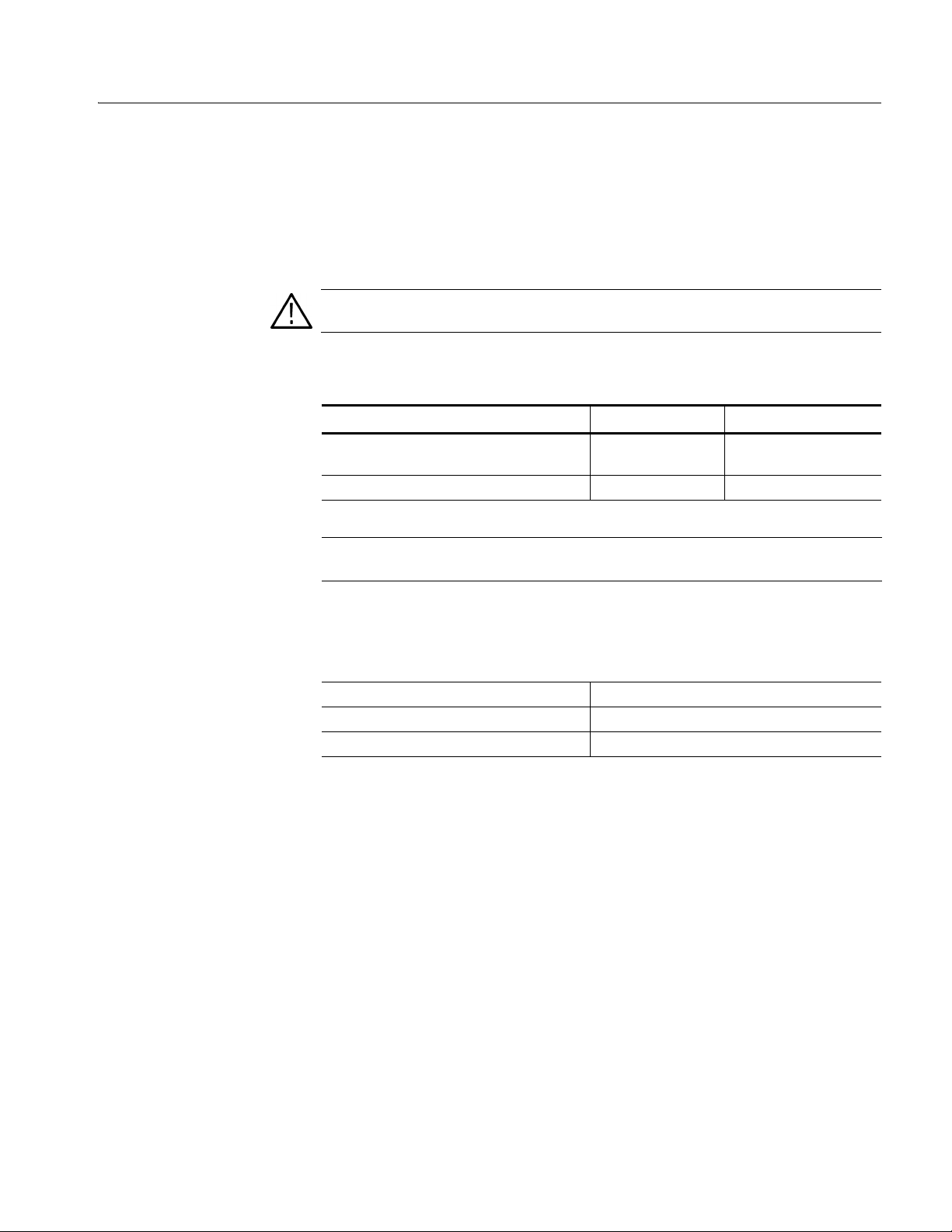
Getting Started
Check Fuse
Check Voltage Settings
Check the fuse that it is the proper type and rating.
Remove the fuse from the fuse holder on the rear panel and check the fuse. To
remove the fuse, turn it counterclockwise with a screwdriver while pushing it in.
There are two types of fuses provided. Table 1-6 lists the fuse types and ratings.
WARNING. To avoid electrical shock, make sure that the power cord is
disconne cted from the socket before checking t he line fuse.
Table 1-6: Fuse and fuse cap part numbers
Fuse Fuse part number Fuse cap part number
0.25 inch × 1.25 inch (UL 198G, 3AG) : 10A
FAST, 250 V
5 mm × 20 mm (IEC 127) : 5A (T), 250 V 159–0210–XX 200–2265–XX
NOTE. The second fuse listed in the table above is approved under the IEC
159–0407–XX 200–2264–XX
standards. This fuse is used in equipment sold in the European market.
Check that you hav e the proper electric al connecti ons. The AWG710&A WG710B
Arbitrary Waveform Generator operates within the following power supply
voltage and frequency ranges:
Connect Power Cord
Line voltage range 100 - 240 V AC
Line frequency 48 - 63 Hz (100 - 240 V AC)
Maximum power 240 VA (220 VA:AWG710)
Connect the proper power cord from the rear panel power connector to the power
system.
AWG710&AWG710B Arbitrary Waveform Generator User Manual 1-11
Page 40
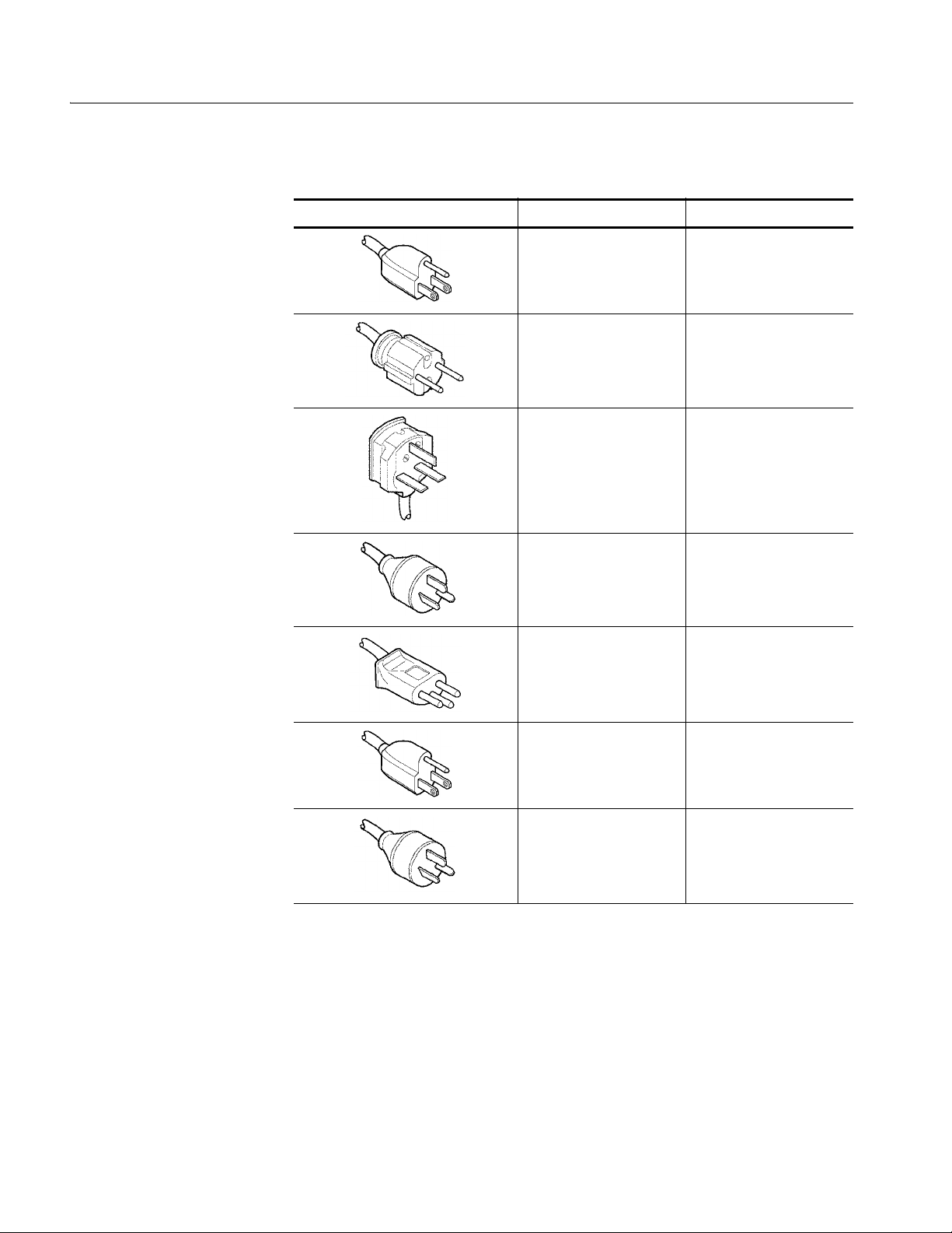
Getting Started
Table 1-7: Power cord identification
Plug configuration Normal usage Option number
North America A0
Europe A1
United Kingdom A2
Standby Power
Australia A3
Switzerland A5
Japan A6
China A10
Push the PRINCIP AL PO WER SWITCH (sho wn in Figure 1- 1) on the rear panel
of the instrument. Power is now applied to the instrument standby circuitry. Once
the instrument is installed, leave the PRINCIP AL PO WER SWITCH on and use
the ON/STBY switch, locate d on the front–panel , to turn the instrumen t on and off.
1-12 AWG710&AWG710B Arbitrary Waveform Generator User Manual
Page 41
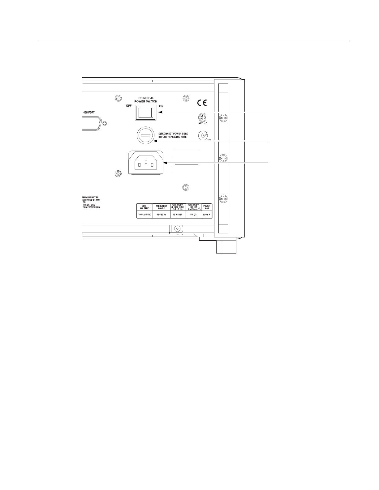
PRINCIPAL POWER
SWITCH
Fuse
Power connector
Getting Started
Figure 1-1: Rear panel power switch, fuse holder, and power connector
AWG710&AWG710B Arbitrary Waveform Generator User Manual 1-13
Page 42

Getting Started
Power On
Push the ON/STBY switch (shown in Figure 1-2) on the lower left side of the front
panel to power on the instrument. Check that the fan is blowing air out of the
instrument.
NOTE. The instrument ne eds to be warmed up f or at least 20 mi nutes and the cloc k
calibrated to operate at its optimum accuracy.
It will take 1 - several minutes to start up after pushing the ON/STBY switch. The
starting time depends on the data length of the waveform file loaded when power
0ff was executed last time.
In addition, AWG cannot start up when floppy disk other than a system disk is
inserted in the floppy disk drive. Please power on after ejecting a disk.
ON/STBY switch
Figure 1-2: Location of the ON/STBY switch
1-14 AWG710&AWG710B Arbitrary Waveform Generator User Manual
Page 43

Getting Started
Power-On Diagnostics
Power Off
The instrument automatically runs power–on self tests to check that the instrument
is operating normally.
Check the results of the po wer–on self tests. If all the di agnostic tests are comple ted
without error, the instrument displays Pass and then displays the SETUP menu
screen.
If the system detects an error, the instrument displays Fail and the error code
number on the screen. You can still operat e the instru ment if you e xit this sta te, but
the wav eform output accur acy is n ot guaranteed un til the error is corrected. To exit
the diagnosis mode, push a ny b utt on. The syste m goes t o the S ETUP menu scree n.
NOTE. Contact your local T ektronix Field Off ice or r epr esentat ive if the in strument
displays an error message. Be sure to record the error code number.
To power off the AWG710&AW G710B Arbitrary Waveform Generator, push the
ON/STBY switch on the front panel.
WARNING. To pr event el ectrical shoc k, remov e all power fr om the instrument, turn
the PRINCIPAL POWER SWITCH on the back pan el to OFF, and disconne ct the
power cord from the instrument. Some components in the AWG710&AWG710B
Arbitrary Waveform Generator are still connected to line voltage after turning off
the instrument from the front–panel ON/STBY button.
CAUTION. To prevent loss of data and/or damage to the hard drive, before the
power off, be sure to confirm the LED of hard drive at the lower right of the front
panel dose not light or blink.
AWG710&AWG710B Arbitrary Waveform Generator User Manual 1-15
Page 44

Getting Started
Repackaging for Shipment
If this instr ument is shipped by comme rcial transportation, use the original
packaging material. If the original packaging is unfit for use or is not available,
repackage the instrument as follows:
1. Obtain a corrugated cardboard shipping carton having inside dimensions at
2. If the instrument is being s hipped to a Tektronix Service Center fo r repair or
least 3 inches greater than the instrument dimensions and having a carton test
strength of at least 125 kg (275 lb.).
calibration, attach a tag to the instrument showing the following information:
The owner of the instrument (with address).
The name of a person at your firm who may be contacted if additional
information is needed.
The complete instrument type and serial number.
A description of the service required.
3. Wrap the instrument with polyethylene sheeting or equivalent to protect the
outside finish and prevent entry of packing materials into the instrument.
4. Cushion the instrument on all sides by tightly packing dunnage or urethane
foam between the carton and the instrument, allowing for 7.62 cm (3 in) of
padding on each side (including top and bottom).
5. Seal the carton with shipping tape or with an industrial stapler.
6. Mark the address of the Tektronix Service Center and your return address on
the carton i n one or more prominent lo cations.
NOTE. Do not ship the instrument with a diskette inside the flop py disk drive. When
a diskette is inside the drive, the disk release button sticks out. This makes the
button susceptible to damage.
1-16 AWG710&AWG710B Arbitrary Waveform Generator User Manual
Page 45

Operating Basics
Page 46

Page 47

Operating Basics
This section provides the following inform ation:
The Controls and Connector s subsection describes the instrument buttons,
The Menu Operat ion s subsection describes how to operate menus and enter
The File Managem e nt subsection describes the overview of the instrument
The Editor Overview subsection introduces th e wav eform edit or functions a nd
The Setup Overview subsection describes the SETUP screen, and simple
The Theory of Operation subsection describes the electrical operation of the
Controls and Connectors
controls, connectors, and typical screen displays.
numeric and text values.
commands and operations for file management tasks.
operations.
operations.
AWG710&AWG710B Arbitrar y Waveform Generator
Front Panel
Figures 2-1, 2-3, and 2-4 show the locations of the front–panel controls and
connectors.
CAUTION. To pre vent data corr uption , do not pu sh the ej ect b utt on while the LED
is on. Doing so can cause data corruption on the floppy disk and cause the
instrument to hang up. If this happens, turn power off then back on again.
To prevent damage to the instrument, do not apply any external voltage to the
output connector or marker connector.
AWG710&AWG710B Arbitrary Waveform Generator User Manual 2-1
Page 48
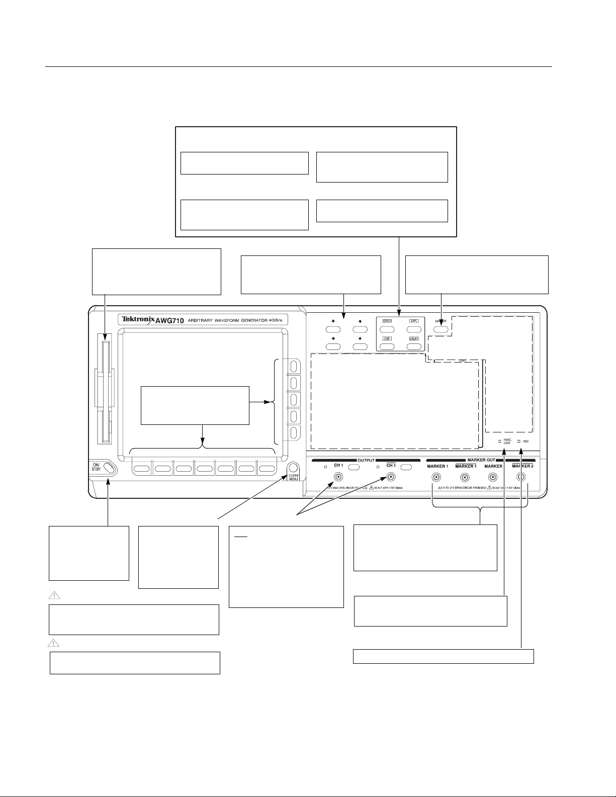
Operating Basics
SETUP menu button
Displays the SETUP Main Menu for
setting the waveform output parameters.
EDIT menu button
Displays the EDIT Main Menu for
creating or editing waveforms, as well as
performing director y and file tasks.
Floppy disk drive
Save or load the various types of data
created or used in the instrument to/from
the 3.5 inch 2HD floppy disk with
MS-DOS format. You can also format a
floppy disk with this instrument.
Bottom and side
bezel menu buttons
The bottom buttons call up
submenus, and the side buttons
execute more detailed operations
within the submenus.
APPL menu button
Displays the APPL Main Menu for running
a specific application program to create
waveforms.
UTILITY menu button
Displays the UTILITY Main Menu for
setting the instrument parameters.
Arrow buttons
Controls up, down, right, and left
movements of the cursor or a selected item;
for example, movements of a selected item
in a dialog box or pop-up menu.
See Figure 2-4
HARDCOPY button
Produces a hardcopy of the screen display,
which can be transferred, as a file, to the hard
disk, a floppy disk, and/or a networked
device.
See Figure 2-3
ON/STBY button
This button is the power
switch in normal
operation. The
PRINCIPAL POWER
SWITCH on the rear
panel must be on.
CLEAR MENU button
Cancels the current
operation and closes
side and submenus.
The display can be
returned to the top level
by pushing this button
repeatedly.
CAUTION
To prevent loss of data and/or damage to the hard
drive, before the power off, be sure to confirm the
floppy disk or hard drive LED is not on or blinking.
CAUTION
To prevent damage to the instrument, do not apply the
voltage to OUTPUT or MARKER connectors.
Output connectors
Provides normal (CH1) and inverted
) waveforms.
(CH1
The maximum output level is 2 V
into a 50 Ω load in Normal mode,
and 1 V
mode and option02. If you use only
one output connector, you must
terminate the other connector using
a 50 Ω termination.
into a 50 Ω load in Direct
p-p
MARKER OUT connectors
Outputs marker signals. Each channel is
equipped with two MARKER OUT connectors.
If you use only one output connector for each
p-p
marker, you must terminate the other
connector using a SMA termination.
PANEL LOCK LED indicator
The LED indicator is on when the front panel
control is locked. You can lock the front panel
controls only through GPIB interface.
HDD LED indicator
The LED indicator is on when the disk drive is in operation.
Figure 2-1: Front panel controls (AWG710)
2-2 AWG710&AWG710B Arbitrary Waveform Generator User Manual
Page 49
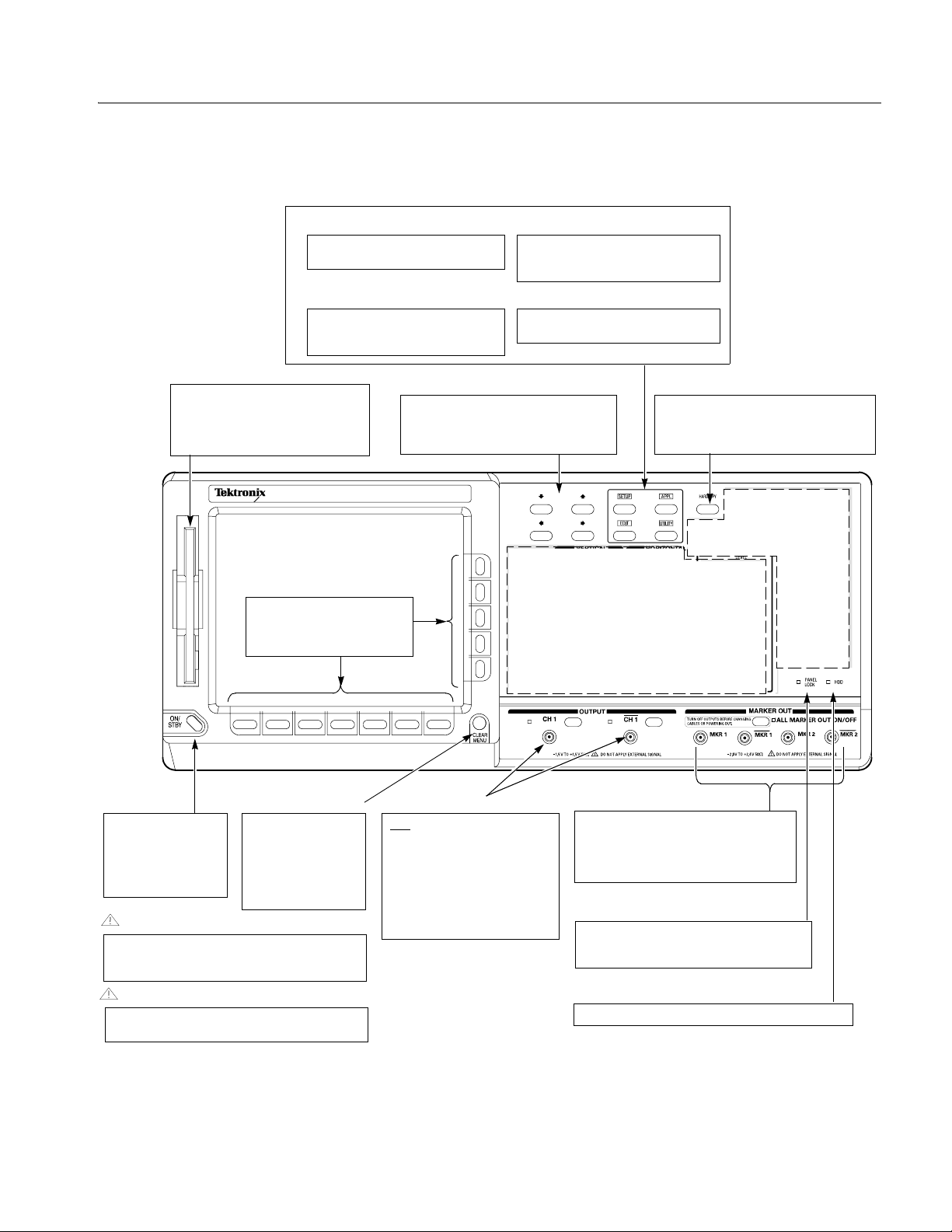
Operating Basics
SETUP menu button
Displays the SETUP Main Menu for
setting the waveform output parameters.
EDIT menu button
Displays the EDIT Main Menu for
creating or editing waveforms, as well as
performing director y and file tasks.
Floppy disk drive
Save or load the various types of data
created or used in the instrument to/from
the 3.5 inch 2HD floppy disk with
MS-DOS format. You can also format a
floppy disk with this instrument.
AWG710B
ARBITRARY WAVEFORM GENERATOR 4.2GS/s
Bottom and side
bezel menu buttons
The bottom buttons call up
submenus, and the side buttons
execute more detailed operations
within the submenus.
APPL menu button
Displays the APPL Main Menu for running
a specific application program to create
waveforms.
UTILITY menu button
Displays the UTILITY Main Menu for
setting the instrument parameters.
Arrow buttons
Controls up, down, right, and left
movements of the cursor or a selected item;
for example, movements of a selected item
in a dialog box or pop-up menu.
See Figure 2-4
HARDCOPY button
Produces a hardcopy of the screen display,
which can be transferred, as a file, to the hard
disk, a floppy disk, and/or a networked
device.
See Figure 2-3
ON/STBY button
This button is the power
switch in normal
operation. The
PRINCIPAL POWER
SWITCH on the rear
panel must be on.
CLEAR MENU button
Cancels the current
operation and closes
side and submenus.
The display can be
returned to the top level
by pushing this button
repeatedly.
CAUTION
To prevent loss of data and/or damage to the hard
drive, before the power off, be sure to confirm the
floppy disk or hard drive LED is not on or blinking.
CAUTION
To prevent damage to the instrument, do not apply the
voltage to OUTPUT or MARKER connectors.
Output connectors
Provides normal (CH1) and inverted
) waveforms.
(CH1
The maximum output level is 2 V
into a 50 Ω load in Normal mode,
and 1 V
mode and option02. If you use only
one output connector, you must
terminate the other connector using
a 50 Ω termination.
into a 50 Ω load in Direct
p-p
MARKER OUT connectors
Outputs marker signals. Each channel is
equipped with two MARKER OUT connectors.
If you use only one output connector for each
p-p
marker, you must terminate the other
connector using a SMA termination.
PANEL LOCK LED indicator
The LED indicator is on when the front panel
control is locked. You can lock the front panel
controls only through GPIB interface.
HDD LED indicator
The LED indicator is on when the disk drive is in operation.
Figure 2-2: Front panel controls (AWG710B)
AWG710&AWG710B Arbitrary Waveform Generator User Manual 2-3
Page 50
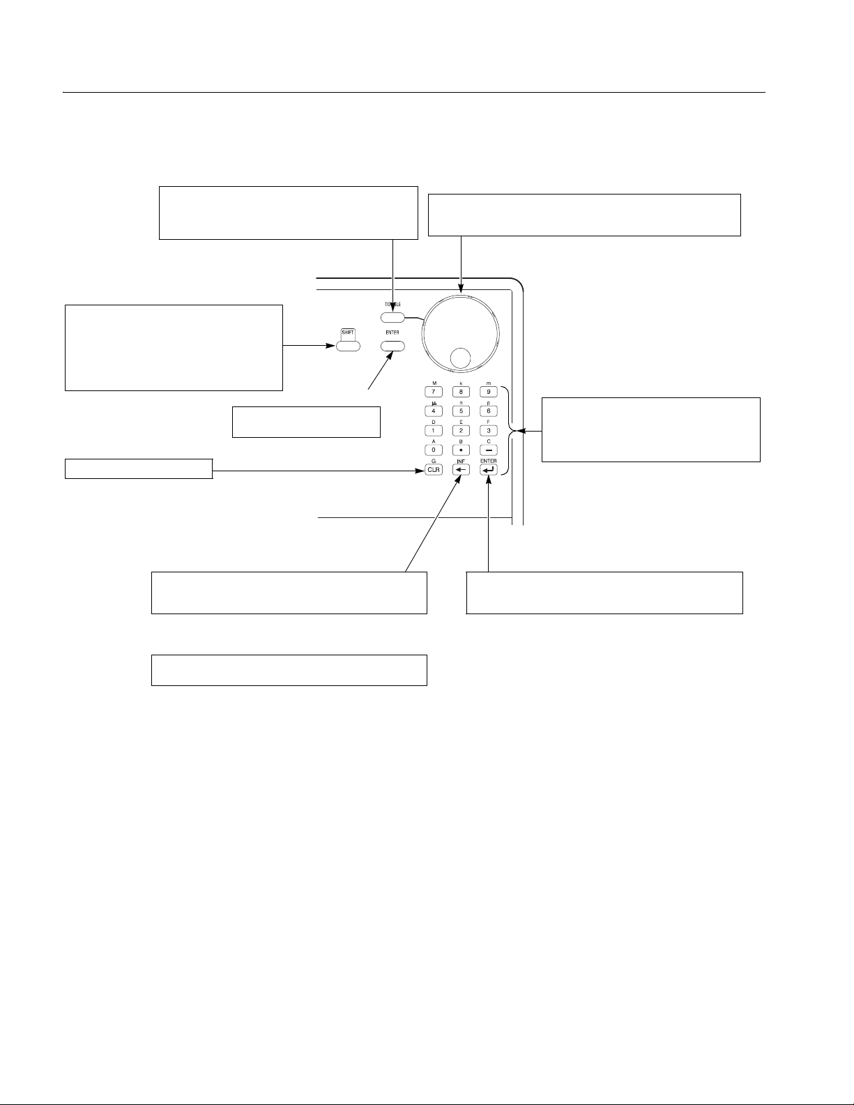
Operating Basics
TOGGLE button
Switches the active cursor on the waveform and pattern
editor. In the sequence editor, this button can be used to
cancel the numeric input mode and make the left and right
arrows available to move the highlight cursor.
SHIFT button
When you push a numeric or unit button while the
SHIFT LED is on, the function shown in blue above
a key is executed. The SHIFT button toggles on
and off. When the instrument displays the File
Name Input dialog box, you can input upper case
characters when the SHIFT LED is on. When you
exit the dialog box, the SHIFT LED also goes off.
This ENTER key has the same
function as that found in keypad.
CLR button
Clears text in an active text field.
Delete button
Deletes a character positioned just left of the text cursor and
moves the cursor to the left by one character. This button does
not function when the text cursor is at the left-most position.
ENTER key
General Purpose knob
Selects a menu item or adjusts a numeric value on the instrument. When
the knob icon is displayed on the screen next to an item, it indicates that
that item can be controlled with the general purpose knob.
Keypad
Enters numeric values. The keys G, M, k, m, µ, n
and p are unit keys. The keys A, B, C, D, E and F
are used to enter a hexadecimal value. These keys
are accessed with the SHIFT button. The unit keys
also work like the ENTER key.
Confirms the numeric or character string you typed and enters it
in the instrument. When using the general purpose knob, push
ENTER to confirm the settings.
INF button
Sets the Repeat Count to Inf. in the sequence editor. This button
can be used only for this purpose.
Figure 2-3: Front panel keypad area
2-4 AWG710&AWG710B Arbitrary Waveform Generator User Manual
Page 51
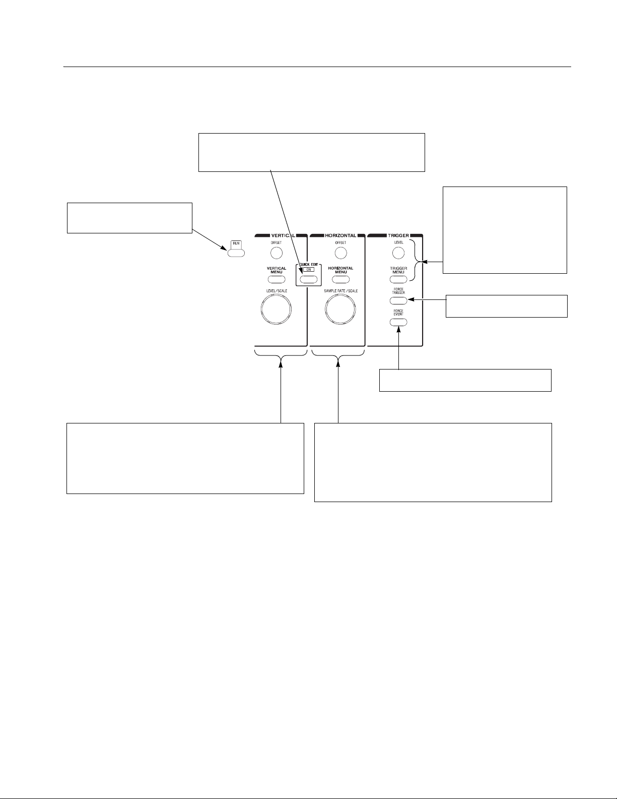
RUN button
Enables waveform output. The signal
output depends on the RUN mode
settings.
QUICK EDIT button
Enters the QUICK EDIT mode from the waveform editor. This button
allows you to edit waveforms that have immediate effect on the output
signal. Use together with the VERTICAL and HORIZONTAL controls for
quick edit.
Operating Basics
TRIGGER controls
Controls the trigger parameters.
Pushing the TRIGGER MENU button
displays the Trigger side menu. This
has the same effect as pushing
SETUP (front)→Tr ig g er (bottom).
The LEVEL knob adjusts the trigger
level.
FORCE TRIGGER button
Pushing the FORCE TRIGGER button
generates an internal trigger event.
VERTICAL controls
Used to control the output vertical axis parameters.
Pushing the VERTICAL MENU button displays the VERTICAL side menu.
This is the same as selecting SETUP (front)→Vertical (bottom).
The OFFSET knob, adjusts the vertical offset.
The LEVEL/SCALE knob adjusts the amplitude.
Figure 2-4: Front panel trigger and output controls
FORCE EVENT button
Pushing the FORCE EVENT button generates an
internal event signal.
HORIZONTAL controls
Used to control the output horizontal axis parameters.
Pushing the HORIZONTAL MENU button displays the Horizontal side menu.
This is the same as selecting SETUP (front)→Horizontal (bottom).
The OFFSET knob adjusts the horizontal position.
The SAMPLE RATE/SCALE knob adjusts the clock frequency.
AWG710&AWG710B Arbitrary Waveform Generator User Manual 2-5
Page 52
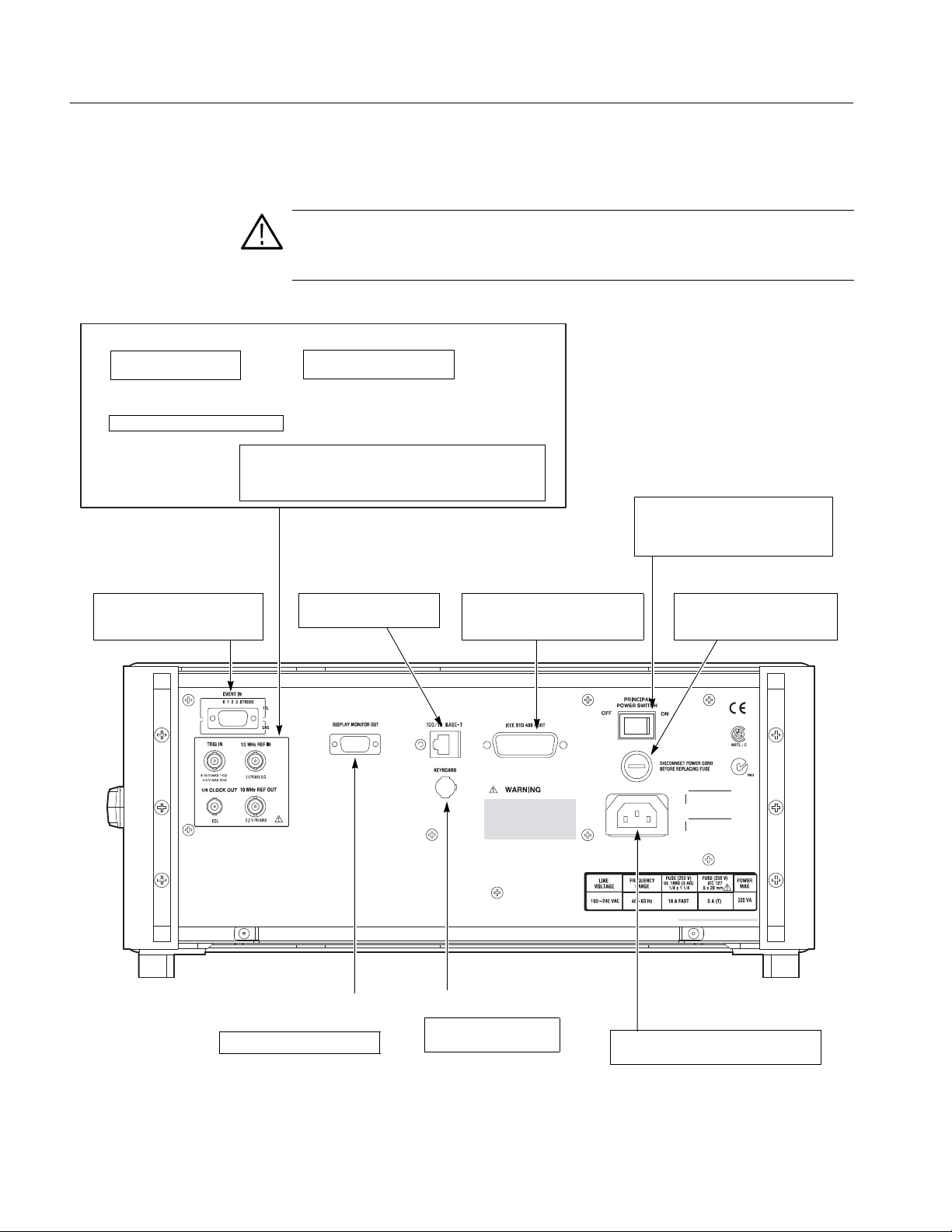
Operating Basics
Rear Panel
TRIG IN connector
External trigger signal
input.
1/4 CLOCK OUT connector
1/4 Sampling clock signal output.
EVENT IN connector
Inputs external event signals. This
signal can be used for sequence
control in Enhanced mode
Figure 2-5 and 2-6 show the rear panel signal and power connectors.
CAUTION. To prevent damage to the instrument, only apply signals within the
stipulated range to the INPUT connector.
Do not apply any external voltage to the OUTPUT connector.
10 MHz REF IN connector
External 10 MHz reference
clock signal input.
10 MHz REF OUT connector
The internal 10 MHz clock reference signal is output when the
internal clock reference is selected. The external clock reference
signal is output when the external clock reference is selected.
The maximum output level is 1 V
100/10BASE-T connector
Connect to the Ethernet
network.
±0.1V into 50 Ω load
p-p
IEEE STD 488 connector
A GPIB connector for remote
computer control through an
IEEE 488 standard parallel interface.
PRINCIPAL POWER SWITCH
Applies power to the standby circuit. In
addition to this switch being on, the front
panel ON/STBY switch must also be
turned on.
Power supply fuse holder
The 10 A fast blow and 5 A (T)
fuse are used for 115 V and
230 V systems, respectively
DISPLAY MONITOR OUT
connector
Connect to an external monitor.
KEYBOARD connector
Connect to a standard PC
101-key keyboard.
Power connector
Connect the provided power cable to this
connector.
Figure 2-5: Rear panel signal and power connectors (AWG710)
2-6 AWG710&AWG710B Arbitrary Waveform Generator User Manual
Page 53

Operating Basics
TRIG IN connector
External trigger signal
input.
10 MHz REF IN connector
External 10 MHz reference
clock signal input.
10 MHz REF OUT connector
The internal 10 MHz clock reference signal is output when the
internal clock reference is selected. The external clock reference
signal is output when the external clock reference is selected.
The maximum output level is 1.2 V
EVENT IN connector
Inputs external event signals. This
signal can be used for sequence
control in Enhanced mode
into 50 Ω load
p-p
DISPLAY MONITOR OUT
connector
Connect to an external monitor.
AWG615
AWG615
100/10BASE-T connector
Connect to the Ethernet
network.
KEYBOARD connector
Connect to a standard PC
101-key keyboard.
IEEE STD 488 connector
A GPIB connector for remote
computer control through an
IEEE 488 standard parallel interface.
PRINCIPAL POWER SWITCH
Applies power to the standby circuit. In
addition to this switch being on, the front
panel ON/STBY switch must also be
turned on.
Power supply fuse holder
The 10 A fast blow and 5 A (T)
fuse are used for 115 V and
230 V systems, respectively
MASTER/SLAVE CONNECTION
These C (clock) and T (trigger) signals are used for only Synchronous
operation between Master unit and Slave unit.
The C OUT n clock signals supplied by Master are inputted into C IN
of Master and Slave.
Similarly, the T OUT n trigger signals supplied by Master are inputted
into T IN of Master and Slave.
VCO OUT connector
Sampling clock signal output.
The maximum output level is
into 50 Ω load
0.4 V
p-p
EXT CLOCK IN connector
External clock signal input.
An acceptable external clock
signal is
0.4 to 2.0 V
50±5 % duty cycle, and
125 MHz to 4.2 GHz frequency
range.
input voltage,
p-p
Power connector
Connect the provided power
cable to this connector.
Figure 2-6: Rear panel signal and power connectors (AWG710B)
AWG710&AWG710B Arbitrary Waveform Generator User Manual 2-7
Page 54
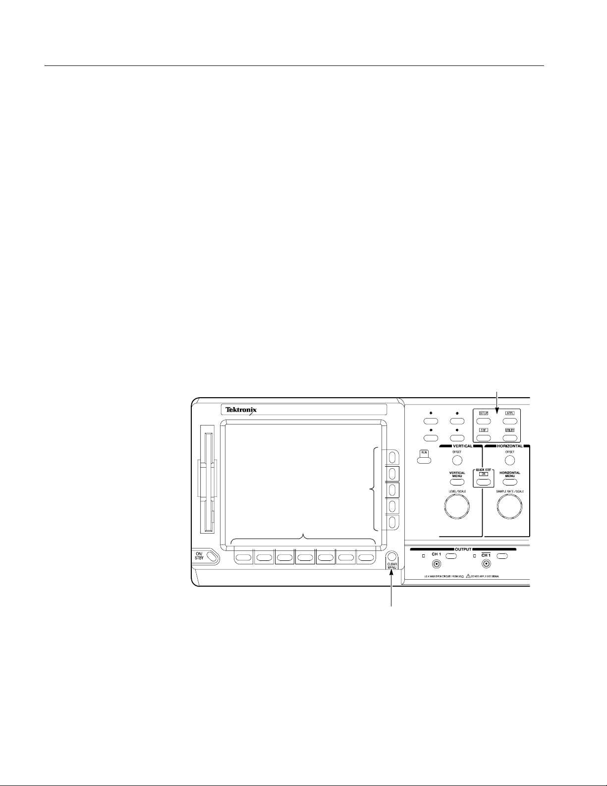
Operating Basics
Menu Operations
This section describes the AWG710&AWG710B Arbitrary Waveform Generator
menu system and numeric and text input metho ds.
Menu System
The AWG710&AWG710B Arbitrary Waveform Generator uses menus to make
selections. There are four menu buttons, labeled EDIT, SETUP, APPL, and
UTILITY, as shown in Figure 2-7. Pushing a menu button displays the
corresponding screen and menu buttons. These menus let you edit waveforms,
initialize instrument settings, define instrument operation, and specify waveform
output parameters.
You select items within the displayed menu by pushing the bottom or side bezel
button nearest t o the menu item. These buttons consist of sev en bottom butt ons and
fiv e side butt ons, as sho wn in Figure 2 -7. These menu be zel b uttons ar e referr ed to
as bottom menu buttons (or bottom buttons) and side menu buttons (or side
buttons).
The CLEAR MENU b utton cancel s the current menu operation , clears t he current
menus from the screen, and exits to the previous instrument state.
Menu buttons
AWG710B
ARBITRARY WAVEFORM GENERATOR 4.2 GS/s
Side menu bezel buttons
Bottom menu bezel buttons
(bottom buttons)
(side buttons)
CLEAR MENU button
Figure 2-7: Menu buttons, bezel menu buttons, and the CLEAR MENU button
2-8 AWG710&AWG710B Arbitrary Waveform Generator User Manual
Page 55
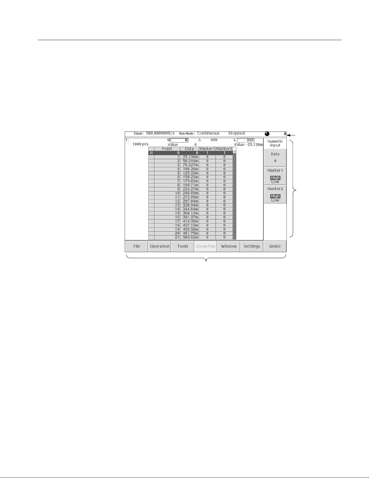
Operating Basics
Menu Elements
Pushing a front–panel menu button displays the screen and bottom menu items
associated with the button. You select a bottom menu item by pushing the button
directly below that menu item.
Pushing a bottom button displays a side menu, pop–up menu, list, or dialog box.
Figures 2-8 through 2-10 show examples of the side menu, pop–up menu and
dialog box, respectively.
Status display
Side menu
Bottom menu
Figure 2-8: Bottom and side menus
You use a side menu button to display a side submenu, set a parameter, perform a
task, or cancel an operation. Table 2-1 describes the side menu button types.
AWG710&AWG710B Arbitrary Waveform Generator User Manual 2-9
Page 56

Operating Basics
Table 2-1: Side menu elements
Menu items Description Menu items Description
Executes the displayed function
immediately.
Switches between two
parameters each time the side
button is pushed.
Allows entering numeric values
using the numeric buttons or the
general purpose knob.
Cannot be used in the current
instrument state (menu item is
grayed out).
Allows making selections by
using the general purpose
knob.
Displays submenus. Note that
the label on the item is followed
by an ellipsis (...).
The pop–up menu example, shown in Figure 2-9, displays a list of choices from
which you make a se lection. Use the ge neral purpose knob or the front–panel arrow
buttons to move up or down in the list. Push the OK side button or the ENTER
front–panel button to confirm the selected item.
Figure 2-9: Pop–up menu example
2-10 AWG710&AWG710B Arbitrary Waveform Generator User Manual
Page 57
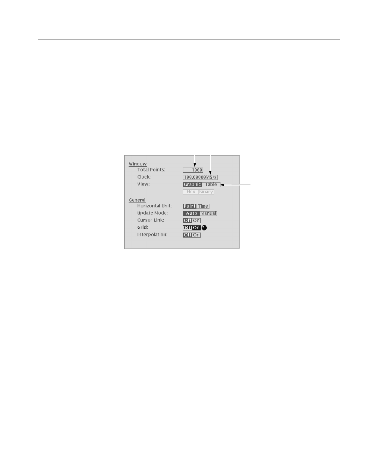
Operating Basics
The dialog box example, sh own in Figu re 2-10, displays a fo rm in which you make
selections or enter values. Use the front–panel arrow buttons to select items or
fields. A sele cted fie ld or item is hi ghlighted. Use the k eypad buttons or the general
purpose knob to change values in selected text/numeric fields or change 1–of–N
fields. A 1–of–N field contains two or more choices of which only one can be
selected at a time.
Push the OK side butt on to con fir m the di alog box. Push the Cancel side button or
the CLEAR MENU button to exit the dialog box without making any changes.
Text/Numeric fields
1-of-N choice
Figure 2-10: Dialog box example
Refer to Numeric Input on page 2-12 and Text Input on page 2-14 for more
information on selecting and entering values in menus and dialog boxes.
Refer to Menu Structures on page 3-3 for information on the menu system.
AWG710&AWG710B Arbitrary Waveform Generator User Manual 2-11
Page 58

Operating Basics
Numeric Input
You can enter numeric values by using either the numeric keypad or the general
purpose knob . If the side menu item displays a v alue, you can alter this v alue usi ng
the general purpose knob or numeric buttons.
Pushing the type of side menu button or selecting a parameter in a pop–up menu
causes the current setting to appear on the right end of the Status Display area as
shown in Figure 2-11.
Knob icon
Underscore
The General Purpose Knob
The Numeric Keypad
Figure 2-11: Knob icon displayed in Status Display area
A knob icon with a numeric value that includes an underscore character indicates
that you can change the value at the underscore location by using the general
purpose knob or k eypad b uttons . By defaul t, the un derscore ch aracter is positioned
under the digit specified depending on the parameters. You can only change the
value repre sented by the digi ts at and to the le ft of the unders core. Use the a and '
arrow buttons to move the underscore to the desir ed position, and then turn the
general purpose knob to change the value.
If the numeric value has the knob icon, but does not have the underscore, then
turning the general purpose knob cycles through a predefined set of values.
When using the general purpose knob, v alues you chan ge in side me nus and menu
screens take effect immediately. Values in pop–up menus are not effective until
you push the OK side button or the ENTER front–panel button.
Figure 2-12 shows the numeric k eypad, with desc ri pt ions of the button operations.
2-12 AWG710&AWG710B Arbitrary Waveform Generator User Manual
Page 59
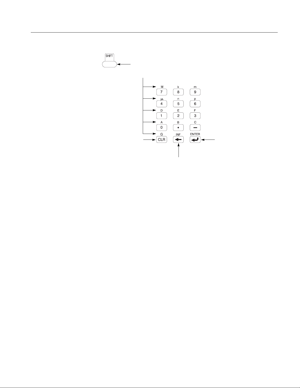
The SHIFT button enters a character
labeled in blue. Push the SHIFT button
and then push the keypad button.
Operating Basics
The CLR button
deletes all characters
in the current field.
The DELETE button deletes the
character to the left of the caret.
The ENTER button
enters the current value
into the instrument.
Figure 2-12: Keypad buttons
The G, M, k, m, µ, n, and p are unit buttons. The A, B, C, D, E, and F buttons are
used for entering hexadecimal values.
To use the numeric keypad to enter a value, position the caret to where you want
to change a val ue, and t hen push a k ey pad b utt on. If you wa nt to ent er a uni t v al ue
labeled in blue just above each numeric button, push or hold down the SHIFT
button, and then push the corresponding numeric button.
To enter or change more than one character, move the care t to the next position to
change. When you are done entering values, push the ENTER button to confirm
the changes and enter them into the instrument. For example, to enter 200.5 µs,
push 2, 0, 0, ., 5, SHIFT and 4 (µ) buttons in this order.
When you enter a value larger than the maximum value in the range for the
parameter , the parameter wil l be set to the maximum val ue. When you enter a v alue
smaller than the minimum value, the min imum value will be set in the pa rameter.
To set to the maximum or minimum value, enter a larger value or smaller value.
This is useful when you do not know the range that can be set.
Note that the current unit is always kept when you just use the ENTER after
entering digits. F or exa mple, suppo se that the Cloc k is currentl y set to100.0 MS /s.
When you press the 5, 0 and ENTER butt ons i n this orde r, the Clock will b e set to
50.0 MS/s. To set the Clock to 500 kS/s, press 0, ., 5 and ENTER buttons, or 5, 0,
0, SHIFT, and 8 (k) buttons in this order.
AWG710&AWG710B Arbitrary Waveform Generator User Manual 2-13
Page 60

Operating Basics
Text Input
Character palette
When you need to assi gn a name to a w a v ef orm f il e or e quatio n, or a IP addr ess t o
the instrument, the i nstrument displ ays a te xt dialog box. See Figure 2-1 3. The text
field is where you ent er or change an existing cha racter string. The charac ter palette
is where you select alphanumeric characters to insert into the text field. You can
also select equation or file names from the name list to insert into the text field.
Caret
Text field
Name list
Text field
Character palette
Text field
Figure 2-13: Three type of Input text dialog boxes
To select a character from the character palette, use the general purpose knob to
highlight a characte r , and then push the ENTER to insert the character into the text
field. Repeat this step until you have entered all characters in the text field. By
default, the character palette is selected. To select text from a file name list, use the
y and b arrow buttons to move the knob icon to the file name list. Table 2-2
describes all the controls you can use for entering and editing text.
2-14 AWG710&AWG710B Arbitrary Waveform Generator User Manual
Page 61

Shortcut Controls
Operating Basics
Table 2-2: Text input button functions
Control Description
General purpose knob Selects the character to insert into the text field.
a and ' arrow buttons Moves the character insertion caret left or right in the text field.
ENTER button Inserts the selected character or character string into the text field.
button Deletes one character to the left of the caret.
CLR button Clears the entire text field.
Numeric buttons Enters numeric characters into the text field.
SHIFT button Enters a selected character in upper case. When you push the SHIFT
button, the SHIFT LED lights. When the dialog box disappears, the
SHIFT LED also goes off.
Figure 2-14 shows the shortcut buttons and knobs that control specific instrument
setup parameters. Using the shortcut controls lets you adjust the output setup
parameters even while you are displaying another menu. Table 2-3 describes the
shortcut controls.
Figure 2-14: Shortcut controls
AWG710&AWG710B Arbitrary Waveform Generator User Manual 2-15
Page 62

Operating Basics
Table 2-3: Shortcut controls
Controls Description
VERTICAL
Displays the Vertical side menu. This is the same operation as selecting
SETUP (front)!Vertical (bottom).
Adjusts the vertical offset parameters. This is the same as selecting
SETUP (front)!Vertical (bottom)!Offset (side), and then turning the
general purpose knob. (except option 02)
Adjusts the amplitude parameters. This is the same as selecting SETUP
(front)!Vertical (bottom)!Amplitude (side), and then turning the
general purpose knob.
HORIZONTAL
mp
Displays the Horizontal side menu. This is the same as selecting SETUP
(front)!Horizontal (bottom).
Adjusts the clock setting. This is the same as selecting SETUP
(front)!Horizontal (bottom)!Clock (side), and then turning the
general purpose knob.
TRIGGER
Displays the Trigger side menu. This is the same as selecting
SETUP (front)!Tri gg e r (bottom).
Adjusts the trigger level setting. This is the same as selecting
SETUP (front)!Tri gg e r (bottom)!Level (side), and then turning the
general purpose knob.
2-16 AWG710&AWG710B Arbitrary Waveform Generator User Manual
Page 63

File Management
Operating Basics
This section is an o verview of t he instrument commands an d oper at io ns for doing
file manageme nt tasks. Ref er to File Management on page 3-225 for more
information.
File Type Extensions
The AWG710&AWG710B Arbitrary Waveform Generator uses numerous file
formats to hold dif ferent types of data. These fil e types are listed i n T able 2-4. Note
that the instrument checks the file format and processes the file based on its
content, regardless of the file extension.
Table 2-4: AWG710&AWG710B Arbitrary Waveform Generator file types
Files Description
Waveform file Use .wfm or .WFM suffix for identification.
Contains waveform data. All signal data must be in waveform format before it
can be output. Created with the waveform editor, by compiling an equation file,
or by converting to waveform format when importing waveforms from external
equipment.
Pattern file Use .pat or .PAT suffix for identification.
Contains pattern data. Created with the pattern editor.
Sequence file Use .seq or .SEQ suffix for identification.
Contains waveform sequence and trigger data. Created with the sequence
editor.
Equation file Use .equ or .EQU suffix for identification.
Contains equations or functions that describe a waveform. Created with the
equation/text editor. Both text editor and equation editor assign .txt suffix by
default, but use .equ suffix to avoid confusion with normal text file.
Text file Use .txt or .TXT suffix for identification.
Contains ASCII text. Created with the equation/text editor.
Setup file Use .set or .SET suffix for identification.
Contains instrument setup and configuration data of both AWG and FG mode.
Created from the SETUP menu.
AWG710&AWG710B Arbitrary Waveform Generator User Manual 2-17
Page 64

Operating Basics
Locating Files
There are three locations for storing waveform data on the AWG710&AWG710B
Arbitrary Waveform Generator. Data can be stored on the instrument hard disk
drive, the instrument floppy disk drive, or a remote storage device accessible
through the Ethernet interface. If the file you want to load is not on the current
drive, use the EDIT menu main screen Drive and Directory bottom menu butto ns
to open side menus that let you change the current drive location. Table 2-5
describes the Drive and Directory bottom buttons.
Table 2-5: Drive and Directory menus
Bottom
menu
Drive Main
Directory Up Level
Side menu Description
Changes the instrument current drive. To select a drive, push
Floppy
Net1
Net2
Net3
Down Level
the appropriate side menu button. Note that there must be a
floppy disk inserted in the instrument floppy disk drive to select
the floppy drive.
Note that the label Net1, Net2 and Net3 vary depending on the
net name settings in the UTILITY menu.
Moves up a directory level.
Moves down a directory level. To move down a directory level,
select a directory name in the pop–up list, and then push the
Down Level side button. The filename list changes to show the
contents of the directory.
Make Directory
Archive
Extract
NOTE. In the following procedures, you may have to push the EDIT button twice
Creates a directory at the current level. To create a directory,
push the Make Directory side button to display the Input New
Directory Name dialog box. Enter the directory name in the
name field, then push the OK side button. The instrument
creates the new directory.
Creates a new file (.tar format) for archive from selected
directory. The archived file keeps hierarchic structure.
Restore the archived file (.tar) to the current directory.
to quit the editor. When the instrument doe s not di splay t he f il e list, pu sh the EDI T
button again. Refer to Saving Files on page 2-21.
2-18 AWG710&AWG710B Arbitrary Waveform Generator User Manual
Page 65

Operating Basics
Copying Files
Renaming Files
Do the following steps to copy a file (single window):
1. Push EDIT (fro nt).
The instrument displays the file list.
2. Select the file to copy.
3. Push File (bottom)!Copy (side)
4. E nter the new name f or the copied file in the file name field
5. Push OK (side).
The file is copi ed and renamed. Also ref er to page 3 -230 for more inf ormation
on the double windows.
NOTE. You can copy a file or all files in another way. Refer to Copying Files on
page 3-227 for those methods.
You can also move a file or all files . Refer t o Movin g F iles on pag e 3-228 for t hose
methods.
Renaming files is similar to Copying files, but the original files are deleted. Do the
following steps to rename a file:
1. Push EDIT (fro nt).
The instrument displays the file list.
2. Select the file to rename.
3. Push File (bottom)!Rename (side).
4. E nter the new name f or the file in the file nam e field.
5. Push OK (side).
The file is renamed.
AWG710&AWG710B Arbitrary Waveform Generator User Manual 2-19
Page 66

Operating Basics
Deleting Files
Read Only Attribute
Do the following steps to dele te a file:
1. Push EDIT (fro nt). The instrument displa ys the file list.
2. Select the file to delete.
3. Push File (bottom)!Delete (side). The instrument displays a message box
asking you to confirm deleting the file.
4. Push OK (side) to delete the file, or Cancel to cancel the operation and keep
the file.
You can also delete all files on the current drive and directory by doing the
following ste p s:
1. Push EDIT (fro nt)!File (bottom)!Delete All (side).
The instrument disp lays a message box asking you t o confi rm deleting all file s.
2. Push OK (side) to delete all files, or Cancel to cancel the operation and keep
all files.
You can change the read only or read/write attributes on a file. Do the following
steps to change the file attribute:
1. Push EDIT (fro nt).
The instrument displays the file list.
2. Select the file to change the attribute.
3. Push File (bottom)!Attribute xxxx (side).
The xxxx is the Read/Write or Read Only attribute of the selected file. Pushing
this side button immediately changes the file attribute.
The file wit h a read onl y attrib ute is marked by , and the directory by . See
Figure 2-15.
2-20 AWG710&AWG710B Arbitrary Waveform Generator User Manual
Page 67
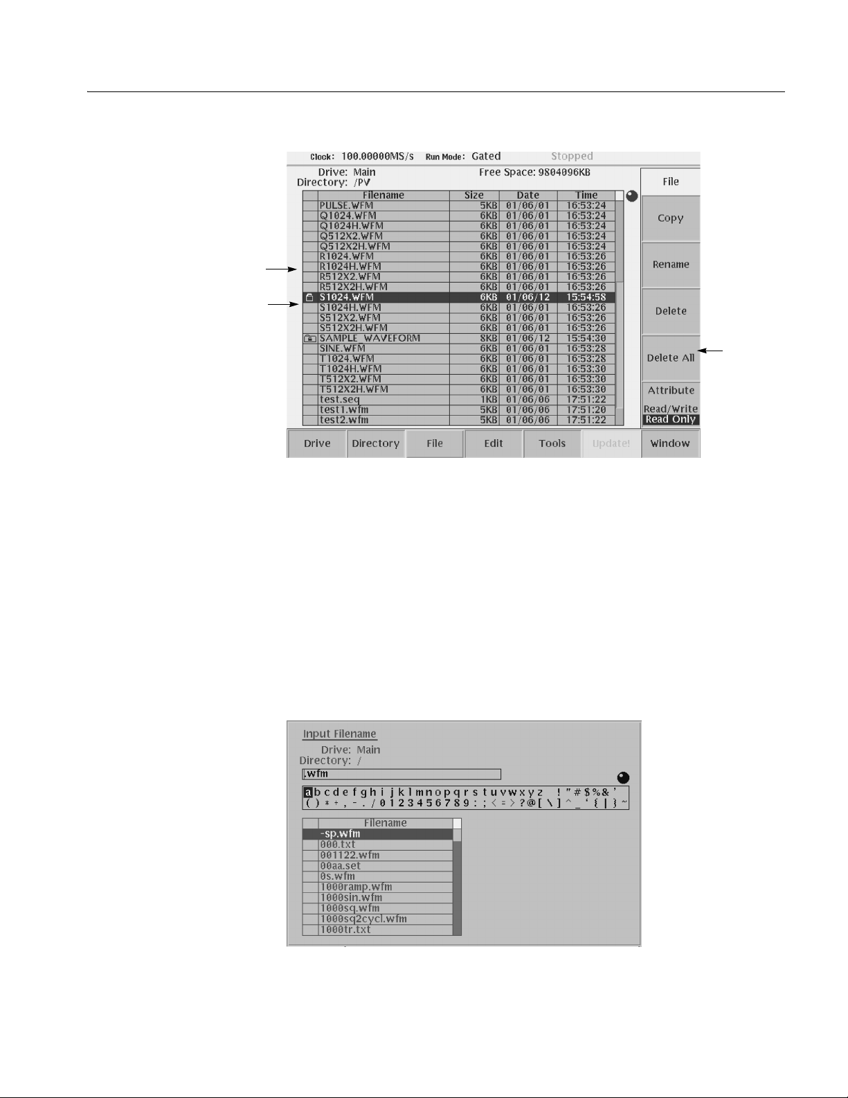
File with read only
Directory with read only
Operating Basics
Attribute
side button
Saving Files
Figure 2-15: Files and directories with read only attribute
You can save files from each editor screen. You have the choice of saving your
waveform data to the current file name or to a new file name. To save a waveform
to its curren t file name, pus h File (bottom)!Save (pop–up)! OK (side).
If you are savin g a waveform for the firs t time, the in strument op ens the Input
Filename dialog box, shown in Figure 2-16. Use this dialog box to enter a file
name. If necessary , you can select a diff erent storage media or di rectory by pushing
the Drive... side menu button. Enter the file name, then push the OK side b utton or
the ENTER front–panel button to close the dialog box and save the file.
Figure 2-16: Input Filename dialog box
AWG710&AWG710B Arbitrary Waveform Generator User Manual 2-21
Page 68

Operating Basics
NOTE. When you e xit an editor wi thout saving edited data, the i nstrument di splays
the message Save the changes you made? Push the Yes side button to save the
waveform data.
To save waveform data to a new file name, push File (bottom)!Save As
(pop–up)!OK (side). The instrument opens the Input Filename dia log box, shown
in Figure 2-16. Use this dialog box to ent er a file name. If neces sary , you can sele ct
a storage media or directory by pushi ng the Drive... side menu button. Enter the file
name, then push the ENTER front–panel button to close the dialog box and save
the file.
If you are saving a file with a record length larger than 960 data points and the
record is not evenly divisible by four, the instrument needs to adj ust the record
length to me et internal me mory record length requirements. The instrument
displays one of the messages show n in Table 2-6. You can push the OK side b utton
to accept the recommended change, or cancel the save and then edit the file to
satisfy the data record length requirements.
Archive, Extract
Table 2-6: Waveform record length adjustment messages
Message Description
Leave as it is The data is saved, as it is, without making changes. The instrument will
display an error message if you try to load a file that does not meet the
instrument waveform constraints.
Append 0 With Level–0 data added after the data, a file with a data length meeting
the requirements is created.
Expand With the waveform data expanded, a file with a data length meeting the
requirements is created.
Expand with Clock With the waveform data expanded, a file with a data length meeting the
requirements is created. In addition, the clock frequency increases without
change in scaling factor. The settings are saved in the file.
Repeat With repetitions of the original data linked, a file with a data length meeting
the requirements is created. If the total length of the linked data exceeds
16M/32M (option 01) points, this will cause an error.
To archive or extract files, do the following steps.
Archive. When you select Directory in the file list, you can make archives for all
the files in the directory and subdirectory.
1. Push EDIT (fro nt).
The instrument displays the file list.
2. Select the file to make archive files.
2-22 AWG710&AWG710B Arbitrary Waveform Generator User Manual
Page 69

Operating Basics
3. Push Directory (bottom)!Archive (side).
The instrument displays the Input archive name dialog box. By default, the
name of <directory na me>.tar is a uto matica lly as signe d. If n ecess ary, you can
change the name.
4. Push OK button, and the archive file will be created in the current directory.
Extract. The archived file is extracted (restored) to the current directory. If the
directory already exists, the existing file will be overwritten.
1. Push EDIT (fro nt).
The instrument displays the file list.
2. Select the file to extract.
3. Push Directory (bottom)!Extract (side).
The instru ment extracts the archived files and directories to current directory.
Remote computer archive operation. AWG710&AWG710B Arbitr ar y Waveform
Generator uses .tar format files. Use th e tar command when you archive with a
remote computer environment. If you are PC user, use tar format archive tool.
The following list describes some restrictions on archive and extract operation.
Blocking factor is 20.
The file name including the file path in the directory is up to 100.
The depth of directory hierarchy is up to 16.
Use the followin g command to make archive file:
tar [–] cvf <tar file name> <file name or directory name>
Use the followin g command to extract archive file:
tar [–] xvf <tar file name>
AWG710&AWG710B Arbitrary Waveform Generator User Manual 2-23
Page 70
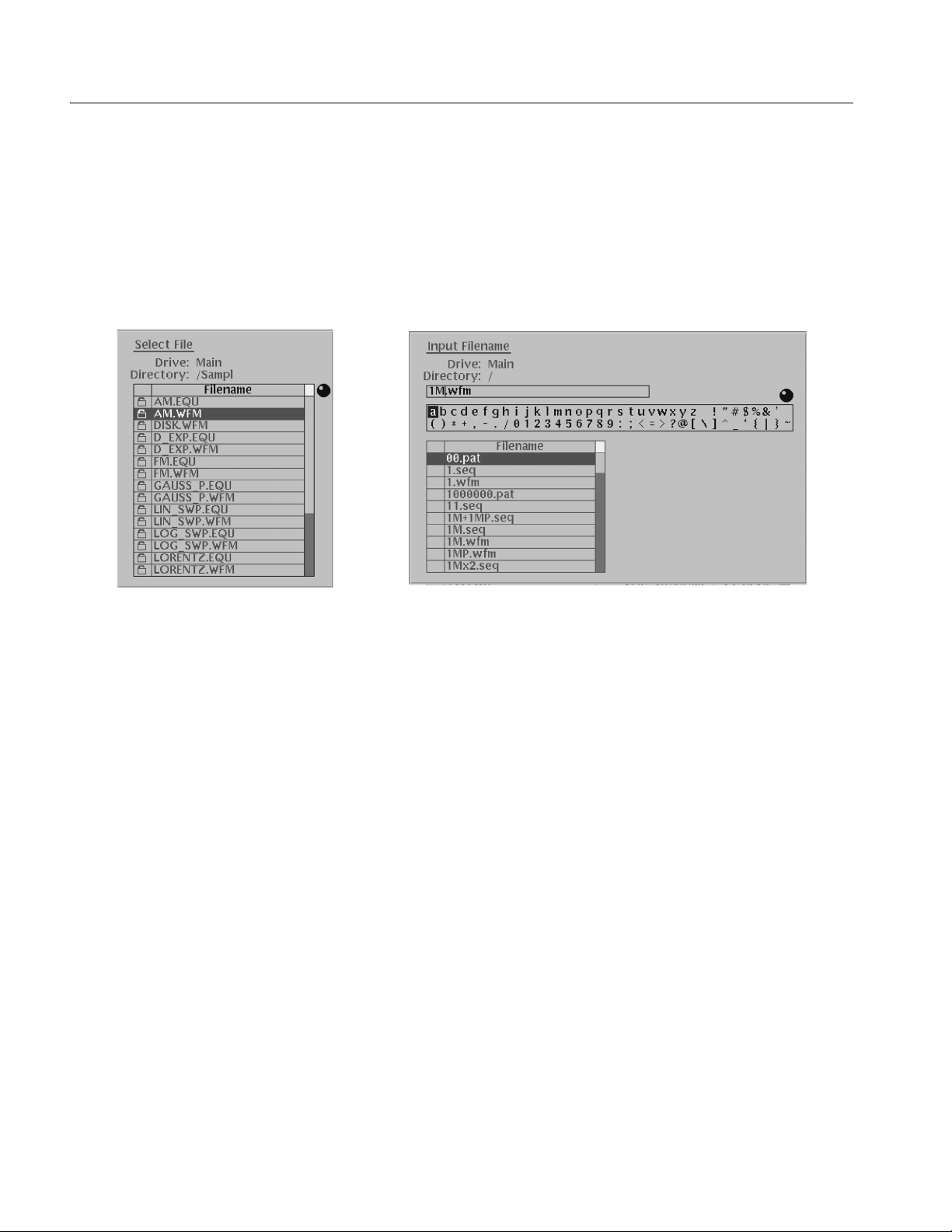
Operating Basics
Quick View
Before loading or handling a file, you sometimes want to look at the content of a
file to confirm the operation. The quick view function displays the view window
and allows you to view a waveform or pattern file selected in a file list. T his
function is always available when a file list is displayed on the screen. See Figure
2-17.
Figure 2-17: File list window examples in which Quick View is available
Select a file from the file list window using the general purpose knob. Press the
SHIFT and ENTER front–panel buttons simultaneously. The view window
displaying the waveform or pattern appears as shown in Figure 2-18.
2-24 AWG710&AWG710B Arbitrary Waveform Generator User Manual
Page 71
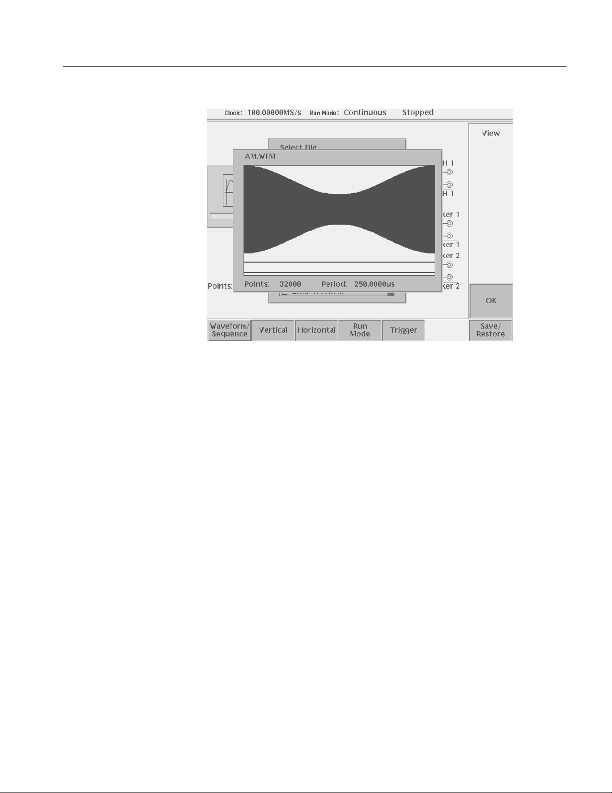
Operating Basics
Figure 2-18: Viewing a file by Quick View function
Push the OK side menu button to close the view window. You cannot view files
other than waveform or pattern in this function.
This function is always available when a file list window or file list dialog box is
displayed on the screen.
AWG710&AWG710B Arbitrary Waveform Generator User Manual 2-25
Page 72

Operating Basics
Editor Overview
This section introduces the editor s creen, desc ribes the screen element s, and
discusses concepts common to most of the editors. Refer to the Reference section
for more detailed information about each waveform editor.
This section also provides an overview of the AWG710&AWG710B Arbitrary
Waveform Generator waveform editors. There are five editors that provide the
tools for creating simple or complicated waveforms. Having more than one edit or
allows you to creat e wa veforms us ing your prefer red method or the one be st suited
to the waveform type.
The Edit menu, displayed by pushi ng the EDIT front–panel b utton, is the main w ay
to open editors. Most of the editor screens have common elements except for the
Sequence and Equation editors.
Editor Modes
The AWG710&AWG710B Arbitrary Waveform Generator provides five editor
modes, as listed in Table 2-7. These editors let you create, edit, and sequence
wavef orms using the techniqu e best suited to your w avefor m. You can access these
editors through the main Edit screen, which is described on page 2-27.
Table 2-7: Editors
Editors Description
Waveform Editor Creates and edits analog waveforms.
Quick Editor Lets you modify and/or output, in real time, any part of a waveform you are
currently editing with the Waveform Editor.
Pattern Editor Creates and edits digital waveform patterns.
Sequence Editor Creates and edits tables that define the sequence and control conditions for
outputting one or more waveforms.
Text/Equation
Editor
Creates, edits, and compiles equation waveform definitions into a waveform
file. You can also use this editor to edit ASCII–format waveform data files
created by other equipment (such as Tektronix Digital Sampling
oscilloscopes).
2-26 AWG710&AWG710B Arbitrary Waveform Generator User Manual
Page 73

Operating Basics
Main Edit Screen
To display the main Edit screen, push the EDIT front–panel button. If there is no
waveform file currently loaded into the edit buffer, the instrument displays the
main Edit screen and a list of files in the current drive, as shown in Figure 2-19.
T abl e 2-8 li sts the bottom menu b utton function s. If the re is a wa vefo rm load ed for
editing, the screen will show the loaded waveform in the appropriate editor.
File list
Figure 2-19: Main Edit screen
Table 2-8: Edit screen bottom menu buttons
Button Description
Drive Specifies the current drive to use for loading or storing waveform files
Directory Lets you navigate and create directories on the current drive
File Lets you copy, rename, delete, and assign attributes to files on the current
drive
Edit Displays the Edit side menu for editing existing or new waveform files
Tools Displays the Tools side menu for importing and converting file data
Update! Updates the waveform file name list. Becomes available during the file lists on
the Net Drive are displayed.
Window Lets you open a single window or double window that displays a file list of a
specified directory or drive. Refer to page 3-230 for information about double
windows.
AWG710&AWG710B Arbitrary Waveform Generator User Manual 2-27
Page 74

Operating Basics
Loading a Waveform File
to Edit
Creating a New Waveform
The default Edit screen displays a list of files in the current drive. T o load a file and
open an editor window, use the general purpose knob or the front–panel arrow
buttons to highlight a file name. Then push the ENTER front–panel button. The
instrument loads th e selected f ile and opens th e editor appropri ate for that f ile type.
You can also edit an existing file by selecting the file in the list, pushing the Edit
bottom button, then pushing the Edit side button. This process takes two more
steps than that described previously. If the file you want to edit is located in a
different directory of the hard disk drive, on a floppy disk, or on a network drive,
use the bottom menu Drive, Directory, and File buttons to change the current dri ve
and load a file from another location. Refer to Fi le Management on page 2-17 for
information on locating and saving fi les.
To create a new waveform file, push the Edit bottom menu button. This displays
the Edit side menu i tems as shown in Figure 2-20. Table 2-9 provides an ov er view
of the Edit side menu button functions.
Edit
selected
file
Figure 2-20: Edit top level menu screen with Edit side menu
Create
a new
waveform
2-28 AWG710&AWG710B Arbitrary Waveform Generator User Manual
Page 75

Operating Basics
Table 2-9: Edit side menu buttons
Button Description
Edit Loads the selected waveform file and opens the appropriate editor screen
New Waveform Opens a new Waveform Editor screen
New Pattern Opens a new Pattern Editor screen
New Sequence Opens a new Sequence Editor screen
New
Text/Equation Opens a new Equation Editor screen
Editor Screen Elements
Window number
Wavefor m
record length
Data edit/display area
Figure 2-21 shows elements that are common to many of the editor screens. W hat
elements are in an editor depends on which editor is open. The Reference section
describes each editor in detail. Refer to Figure 2-21 to familiarize yourself with the
common screen elements of most of the editors.
Right cursor
position
field and
data value
Status
Knob icon
Side
menu
Wavefo rm
file name
Clock
frequency
Left cursor
position
field and
data value
Cursor-to-cursor
distance
(edit area)
Run
mode
Position of data
viewed in overall
waveform record
display area
Active
cursor
position
Marker display
Bottom menu
Figure 2-21: Editor screen elements
AWG710&AWG710B Arbitrary Waveform Generator User Manual 2-29
Page 76

Operating Basics
Cursors and Editing
The edit window cursors define the data affected by all edit operations except the
T ools menu commands. Most of the edit commands affe ct the data located bet ween
the left and right cursor positions. This region is called the edit area or scope.
Figure 2-22 shows an example of an edit area. In this example, all data is located
from left cursor position 300 to right cursor position 779.
Other edit operations use the active (selected) cursor position for inserting
waveform data. The active cursor is shown as a solid vertical line. The inactive
cursor is shown as a dashed vertical line.
Left cursor, (active)
selected
Edit
area
Edit area
Left cursor, 300
position (active)
Right cursor, 779
position
(inactive)
Figure 2-22: Cursors and edit area
When you edit a waveform, you must first specify the edit area or a single cursor
position, depending on the operation you want to do. To select the active cursor,
push the TOGGLE front–panel b utton t o switch betwee n the left an d right curs or.
To move a cursor, turn the general purpose knob, use the left or right arrow keys,
or use the keypad or keyboard to enter a position in the cursor position field. The
cursor position field is active when the corresponding cursor is active.
2-30 AWG710&AWG710B Arbitrary Waveform Generator User Manual
Page 77

Operating Basics
Followi ngs are more cursor operations that are av ailable by using the SHIFT button
on the front–panel:
Push the SHIFT front–panel button then turn the general purpose knob to
accelerate the cursor transfer speed.
Push the SHIFT front–panel button then push the TOGGLE front–panel
button to mo ve the ina ctiv e cursor to the ac tiv e cursor positio n (the two cur sors
overlap).
Push the SHIFT front–pa nel b utton the n push the ENTER front–p anel b utt on
to move left curso r to 0 point and to move the right cursor to the maximum
point.
Multiple Editor Windows
The AWG710&AWG710B Arbitrary Waveform Generator can open and edit up
to three waveform and/or pattern files, in any combination. The waveform data is
displayed in sepa rate windo ws, wit h each windo w stack ed ve rtically on the scree n.
Multiple editor windows are very useful for creating a new waveform by c utting
and pasting wa veform dat a from other f iles. Figure 2-2 3 shows a n example of t hree
opened editor windows (one pattern and two waveform files).
Figure 2-23: Multiple editor windows
AWG710&AWG710B Arbitrary Waveform Generator User Manual 2-31
Page 78

Operating Basics
NOTE. You cannot open a sequence, text, or equation file from the Waveform or
Pattern Editor. If you are in the Waveform or Pattern Ed itor, you must exit to the
EDIT menu main screen and then load the sequence, text, or equation file.
Some editor informatio n is not di splayed when three Wav eform editor wi ndows ar e
open.
Opening Multiple Editor Windows. Do the following steps to load waveform data
file into an edit or window:
1. From the editor screen, push File (bottom)!Open... (pop–up)!OK (side).
The Select File dialog bo x appears. If you cannot s elect the Open... menu it em,
you already have three windows opened.
2. Select a waveform or pattern file from the Select File list.
If necessary, use the Drive..., Up Level, or Down Le vel side menu to select
the location where the file to lo ad is located .
3. Push the OK side button.
The instrument opens a ne w window for the wavefor m or pattern data, stacking
the windows vertically to fit on the screen. If you attempt to load a sequence,
text, or equa tion file, you will receive an error message.
Creating a New Waveform or Pattern in a Multiple Editor Window. To create a new
empty W a vef orm or Patt ern Editor windo w, push File (bottom)! New W av eform
or New Pattern (pop–up)!OK (side). The instrument opens a new window for
the wav eform or pattern editor , stacking the windo ws vert ically to f it on the screen.
If you cannot select the New Waveform or New Pattern pop–up menu item, you
already have three editor windows opened.
Selecting the Active Edit Window. Although you can have up to three open editor
windows, you can only do editing tasks in one window at a time. To select the
active window, push Window (bottom)!Window1, W indow2, or Window3
(side). All editing operations will affect the waveform data in that window until
you change to another editor window.
2-32 AWG710&AWG710B Arbitrary Waveform Generator User Manual
Page 79

Operating Basics
Quitting Editors
There are three methods to quit an editor.
Using the File Bottom Menu.
1. Push File (bottom)!Close (pop–up) to quit the waveform and pattern editors
or
push File (bottom)!Close (side) to quit the sequence and text/equation
editors.
2. If you have made no modifications to t he data, the editor is immedi ately exited.
If you have made modif ications, the message box Save the ch anges you made?
appears. Push the Yes, No, or Cancel side button.
Using the Window Bottom Menu.
You can close the window by using Window (bottom) menu for waveform editor
and pattern editor.
1. Push Window (bottom) ! Close Selected Window or Close Unselected
Window (side).
Close Selected Window closes current window and Close Unselected
Window closes the window which is currently unselected.
2. If you have made no modifications to t he data, the editor is immedi ately exited.
If you have not saved the data after modifications, the message box Save the
changes you made? appears. Push Yes, No, or Cancel side button.
Using the EDIT Button.
1. Push EDIT button on the front–panel.
2. If you have made no modifications to t he data, the editor is immedi ately exited.
If you have not saved the data after modifications, the message box Save the
changes you made? appears. Push Yes, No, or Cancel side button.
Refer to page 2-21 for saving files.
AWG710&AWG710B Arbitrary Waveform Generator User Manual 2-33
Page 80
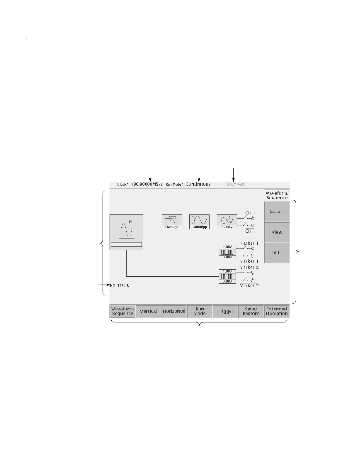
Operating Basics
Setup Overview
The Setup screen is where you load and set up the waveform for output. This
section gives you an overview of the Setup screen, how to load a file, how to set
the signal output parameters, and how to enable signal output. Refer to The Setup
Menu on page 3-33 in the Reference section for more information.
Main Setup Screen
Wavefo rm
parameter icons
Number of points for
loaded waveform
To display the main Setup screen, push the SETUP front–pane l button. The
instrument displays the main Setup screen as shown in Figure 2-24. Table 2-10
describes t he screen waveform parameter icons. Table 2-11 lists the bottom menu
functions.
Clock frequency Run mode Instrument status
Side
menu
area
Bottom menu
Figure 2-24: Main Setup screen (except option02)
2-34 AWG710&AWG710B Arbitrary Waveform Generator User Manual
Page 81
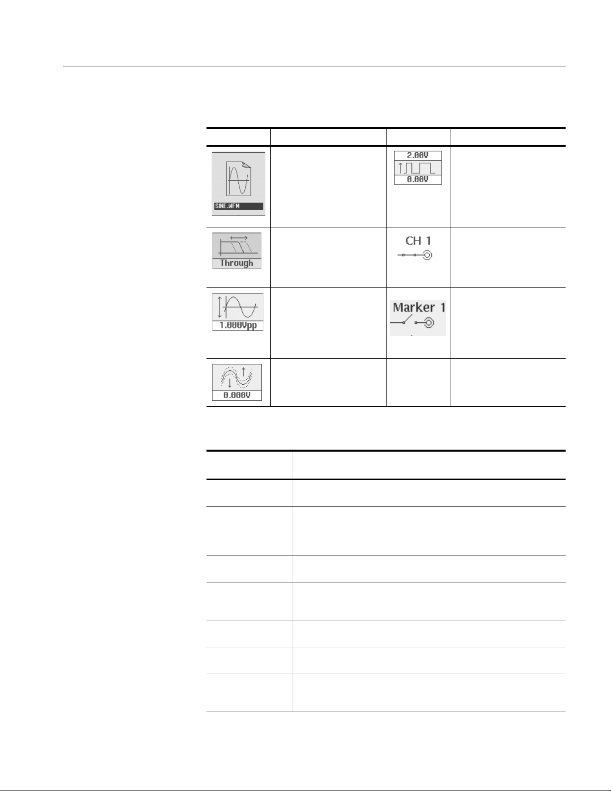
Table 2-10: Setup screen parameter icons
Icon Description Icon Description
Displays the file name of the
waveform, pattern, or
sequence file loaded for
output.
Note: use the View button to
display the loaded waveform.
Displays the lowpass filter
setting through which the
waveform is passed.
(except option 02)
Displays the peak–to–peak
signal amplitude setting.
Displays the signal offset
setting.
(except option 02)
Displays the digital output and
marker signal minimum and
maximum voltage settings.
Indicates that the channel
output is enabled or disabled.
If the switch is shown open,
that channel output is
disabled.
Indicates that the marker
output is enabled or disabled.
All Marker outputs are
controled by the ALL
MARKER OUT ON/OFF
button.
Operating Basics
Table 2-11: Setup bottom menu buttons
Bottom menu
button
Waveform/Sequence Displays the side menu for loading, viewing, editing waveform files, and for
Vertical Displays the Vertical side menu for setting waveform peak–to–peak
Horizontal Displays the Horizontal side menu for setting the clock source, clock
Run Mode Displays the Run Mode side menu for setting the instrument run mode.
Trigger Displays the Trigger side menu for setting trigger source, slope, level,
Save/Restore Displays the Save/Restore side menu to save and restore setup output
Extended Operation Displays the Extended Operation side menu to change the operation mode
Description
entering the FG mode main screen.
amplitude, offset, lowpass filter, marker, and other output parameters.
The product which has option 02 doesn’t have offset and lowpass filter
function.
frequency, and marker signal delay parameters.
Refer to Run Modes in the Reference section for an explanation of the
different run modes.
external trigger impedance, and interval parameters.
parameters.
such as FG mode, Waveform Mixing mode and Synchronous Operation
(AWG710B only) mode.
AWG710&AWG710B Arbitrary Waveform Generator User Manual 2-35
Page 82
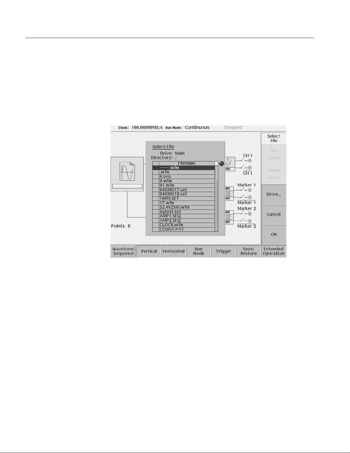
Operating Basics
Loading a Waveform File
to Output
Do the following steps to load a waveform file into the Setup screen:
1. Push the Waveform/Sequence bottom menu button.
This opens the Waveform/Sequence side men u.
2. Push the Load... side button. The instrument opens the Select Fil e list as shown
in Figure 2-25.
Figure 2-25: Select File dialog on the Load menu
3. Use the general purpose knob or y an d b arrow b uttons to select the f ile name
to load. If the file you want to load is located in a different drive or directory,
use the side menu buttons to change the current drive.
4. Push the ENTER front–panel button or OK side button. The instrument loads
the file and displays the file nam e in the selected channel file icon. Push the
Cancel side button to exit the file load process.
The procedures above explains how to load a waveform or pattern into the
wavef orm memory, and/or sequence file into the sequence memory, which will be
scanned to output. The waveform memory, sequence memory and the edit buffer
are completely independent. So, you can edit a waveform, pattern, sequence or
equation/text while outputting an another waveform or sequence.
However, when you push SETUP (front–panel)!Waveform/Sequence
(bottom)!Edit (side) to copy the waveform in the waveform memory to the edit
2-36 AWG710&AWG710B Arbitrary Waveform Generator User Manual
Page 83
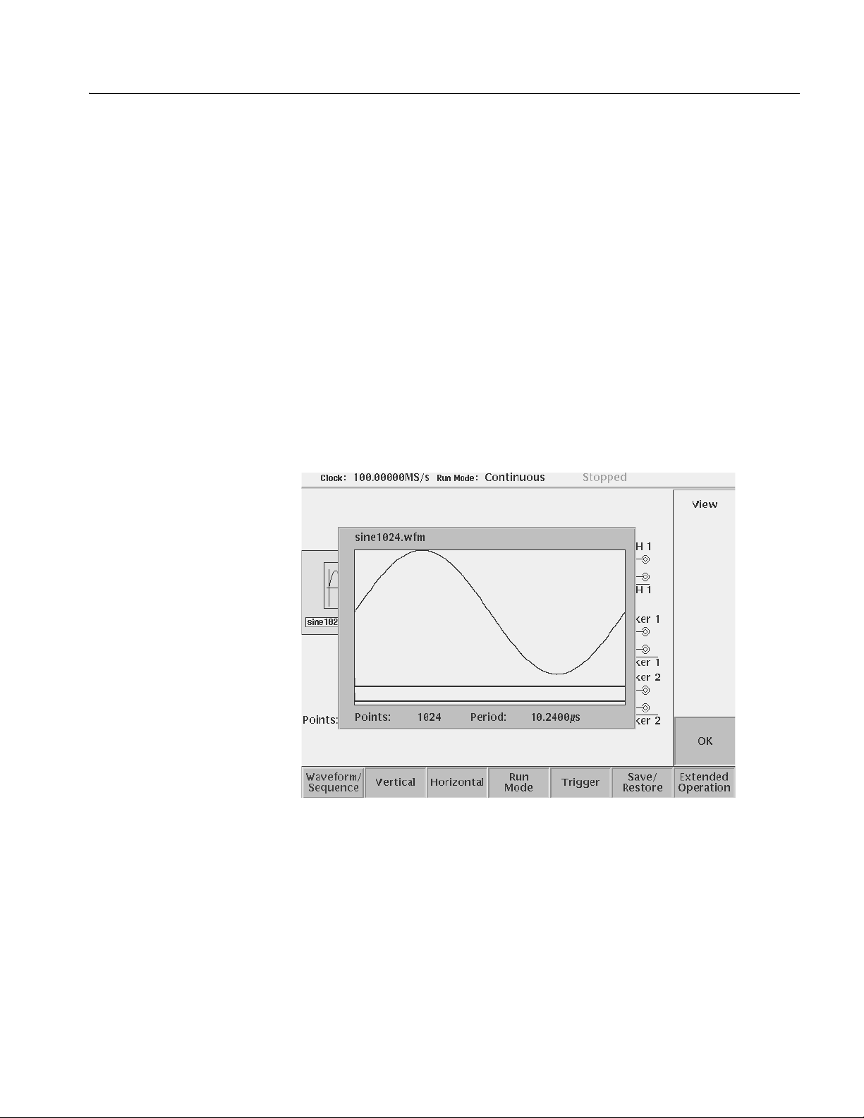
Operating Basics
buffer, you must save the currently edited waveform, pattern, sequence or
equation/text into a file.
You can enter into the QUICK EDIT mode only from the waveform editor. When
you enter into the quick edit mode, the instrument copies the data in the edit buffer
into the undo buffer. All the changes you make immediately reflect to the data in
the edit buffer, and also to the data in the waveform memory if that data is being
loaded to output.
Before loading, you can vie w a wa v eform or pa tter n. Refer to Qui c k View on page
2-24 for more detail.
Viewing a Waveform
T o view the loaded waveform file, push the View side menu button. The inst rument
opens a window on the scr een that displays the wa veform, as sho wn in Figure 2-26.
Push the OK side menu button or ENTER front–panel button to close the view
window.
Figure 2-26: Viewing a file in the Setup screen
Note that the View function does not display the waveform in the waveform
memory , b ut dis plays the wa v eform in t he f ile th at you spe cif ied. Ev en thoug h you
change the waveform with the editor and update the waveform memory, the View
function still displays the waveform before the update unless you save the file.
AWG710&AWG710B Arbitrary Waveform Generator User Manual 2-37
Page 84

Operating Basics
Editing a Waveform
Setting Waveform Output
Parameters
T o edit the loaded waveform file, push the Edit... side menu button. The inst rument
opens the appropriate edit window for the previously loaded file type.
If you have not loaded a file in the Setup screen, the instrument displays the
message No output data, and you cannot enter into the editor.
The editors are described in m ore detail in the Reference section be ginning on page
3-55.
The Setup side menus provide commands for setting and adjusting waveform
output parameters. The steps for setting output parameters are discussed in detail
in the Reference sect ion beginning on page 3 -33. Table 2-12 provides an o v er vie w
of the Setup side menu operations.
Table 2-12: Setup output parameter operations
Bottom
button
Wavefor m/Seq
uence
Side
button Description
Load...
View
Displays the Select File dialog box that lists files in the current
drive and directory. Select a file to load or use the side menu
buttons to change drives and/or directories.
Displays the loaded file in a window. Push the OK side menu
button to close the view window.
Edit...
Vertical Filter
Amplitude
Offset
Marker...
Output...
Opens the appropriate editor for the loaded file.
Selects lowpass filter to insert into signal path. Filter values
are Through (no filter), 20 MHz, 50 MHz, 100 MHz, and 200
MHz. Use the general purpose knob to enter new
values.(except option 02)
Sets the signal peak–to–peak amplitude in increments of
0.001 V. The maximum value is 2 V
V
in direct mode. Use the general purpose knob or the
p–p
keypad to enter new values.
Sets the signal offset value in increments of 0.001 V. The
offset voltage range is ±0.5 V. Use the general purpose knob
or the keypad to enter new values.(except option 02)
Displays a side menu to set Marker 1 and Marker 2 signal high
and low values. The marker signal voltage range is -2.0 V to
2.45 V (-1.1 V to 3.0 V :AWG710) and maximum amplitude is
1.25 V
general purpose knob or the keypad to enter new values.
Toggles normal output to direct output.(except option 02)
into 50 Ω ( 2.5 V
p–p
into 50 Ω : ΑΩΓ710). Use the
p–p
in normal mode and 1
p–p
2-38 AWG710&AWG710B Arbitrary Waveform Generator User Manual
Page 85

Table 2-12: Setup output parameter operations (cont.)
Operating Basics
Bottom
button
Horizontal Clock
Run Mode Continuous
Trigger Source
Side
button Description
Clock Ref
Clock Src
(AWG710B only)
Triggered
Gated
Enhanced
Slope
(or Polarity)
Level
Impedance
Sets the clock sample rate from 50 kS/s to 4.0 GS/s.
Sets the reference clock source to either Internal or External.
A valid external clock signal is 10 MHz ±0.1 MHz with a
voltage level of 0.2 to 3.0 V
Sets the clock source to either Internal or External. A valid
external clock signal is 125 MHz to 4.2 GHz with a voltage
level of 0.4 to 2.0 V
Displays the Run Mode side menu for setting the instrument
run mode. Refer to The Run Mode Menu section on page 3-44
for an explanation of the different run modes.
Sets trigger source to Internal or External. If External selected,
all other side menu items are not selectable except Interval.
Sets the trigger slope or gate polarity to Positive or Negative.
Sets the trigger signal level. The trigger level range is ±5.0 V
in 0.1 V increments.
Sets the external trigger input line impedance to either 50 Ω
or 1 kΩ.
p–p
.
p–p
.
Outputting a Waveform
Interval
Save/Restore Save Setup
Restore Setup
Extended
Operation
FG...
Wavefor m
Mixing...
Sync Master...
(AWG710B only)
Sync Slave...
(AWG710B only)
Sets trigger interval from 1.0 µs to 10.0 s.
Save the setup parameters set by SETUP window and
Extended Operation mode window as a setup file.
Restore a setup file.
Enters the FG mode for easy generate of standard functional
waveform.
Enter the Waveform Mixing mode.
Enter the Sync-Master of the Synchronous Operation mode.
Enter the Sync-Slave of the Synchronous Operation mode.
T o output a loaded waveform, push the CH 1 OUT and/or CH 1 OUT and/or ALL
MARKER OUTPUT ON/OFF front–panel button(s), th en the RUN front–panel
button. The LEDs near each button light up to indicate th ey are enabled. The
instrument outpu ts t he w a v efor m de pendin g on t he Run mode . You can turn eith er
or both channel outputs and marker outputs on or off while the instrument is
running by pushing the CH 1 OUT or CH 1
OUT or ALL MARKER OUTPUT
AWG710&AWG710B Arbitrary Waveform Generator User Manual 2-39
Page 86

Operating Basics
ON/OFF buttons. To stop the waveform output, push the RUN button so that the
LED turns off.
Saving and Restoring
Setup Parameters
The waveform or pattern file contains only the waveform and clock information.
When you load a waveform or pattern file, the output signal will use the current
instrument setup parameters.
T o save you from doing a manual setup proced ure each t ime you loa d a wa ve form,
the AWG710&AWG710B Arbitrary Waveform Generator lets you save setup
parameters into a setup file. You can then restore the saved settings for use with
waveforms.
The setup parameters of the AWG mode and the Extended Operation mode are
saved in a setup file . When a s etup f ile is restore d, settings in both AWG mode and
Extended Operation mode will replace the contents of a setup file.
Do the following steps to save the current setup parameters:
1. Push SETUP (front)!Save/Restore (bottom)!Save Setup (side).
The Input Filename dialog box appears.
2. E nter a setup file name.
The setup file name must have the extension .set.
3. Push the OK side button.
The setup information is saved to the designated file.
Do the following steps to restore setup pa rameters fro m a file:
1. Select SETUP (front)!Save/Restore (bottom)!Restore Setup (side).
The message box displaying Restoring setup destroys current settings.
appears. The instrument then opens the Select Setup Filename dialog box.
2. E nter or select the setup file na me to load.
3. Push the OK side button to load the file and restore the setup parameters, or
push the Cancel side button to exit the restore process without loading the
setup file.
2-40 AWG710&AWG710B Arbitrary Waveform Generator User Manual
Page 87

Theory of Operation
Operating Basics
This section presents an overview of the AWG710&AWG710B Arbitrary
Waveform Generator hardware, data struct ures, and operating mo des.
Block Diagram
Figure 2-27 and Figure 2-28 show the main hardware blocks that make up the
AWG710& AWG710B Arbitrary Waveform Generator.
CPU. The CPU controls the whole instrument using the GPIB interface, fl oppy disk
connection, 100/10BASE–T Ethernet connection, user interface through the
display screen and the front–panel, and so forth.
Clock Oscillator. You can select either the internal or external reference clock
source by using the SETUP horizontal menu.
If you select th e external source , the reference si gnal connected to t he 10 MHz REF
In connector on the rear panel will be used.
The internal clock is from the reference clock oscillator, which uses direct digital
synthesis (DDS). Figure 2-27 shows the clock oscillator configuration.
Trigger Control. The Trigger Control block controls the Memory Address Control
in the operation mode that you specified fro m the RUN MODE menu.
Waveform Memory and Shift Register. The Waveform Memory block has 8 bits for
waveform data and 2 bits per channel for markers, thus a total length of 32.4 M
/64.8 M (option 01) (16.2 M /32.4 M (option 01) :AWG710) points. You can set
any valu e from 960 poin ts to 32.4 M/64. 8 M (opti on 01) (16.2 M /32.4 M (o ption
01) :AWG710) points for the length of w a v efo rm data. It mu st be i n incr ements o f
4.
The Shift Register bloc k is use d to provide waveform data fr om the DAC at a rate
up to 4.2 GS/s (4.0 GS/s : AWG710).
RUN modes. Selecting a RUN mode from the SETUP menu causes one of the
following to operate the AWG710&AWG710B Arbitrary Waveform Generator:
Table 2-13: Run modes
Modes Descriptions
Continuous Consecutively output regardless of existence of a trigger signal.
Triggered The output signal is obtained only once when one of the following is input:
An external trigger signal from the rear panel’s TRIG IN connector.
A trigger signal generated with the front–panel’s FORCE TRIGGER button.
A trigger command from remote device.
AWG710&AWG710B Arbitrary Waveform Generator User Manual 2-41
Page 88

Operating Basics
Table 2-13: Run modes (cont.)
Modes Descriptions
Gated The waveform is output only while:
An external trigger signal from the rear panel’s TRIG IN connector.
A gate signal through the front–panel’s FORCE TRIGGER button is TRUE.
A control command such as trigger or event from remote device. (Except
the Synchronous operation mode)
Enhanced The waveform is obtained, in the order defined with the sequence, based on:
A trigger signal (for example, an external trigger signal from the rear panel’s
TRIG IN connector).
An event signal from the rear panel’s EVENT IN connector.
An trigger signal from the front panel’s FORCE TRIGGER button.
An event signal from the front panel’s FORCE EVENT button.
A control command such as trigger, event or jump from remote device.
(Except the Synchronous operation mode)
Extended operation. Selecting a Extended operation from the Extended Operation
menu causes one of the following to operate the AWG710&AWG710B Arbitrary
Waveform Generator:
Table 2-14: Extended operation
Modes Descriptions
FG Enter the FG mode for easy generate of a standard functional waveform.
Wavefor m
Mixing
Synchronous
Operation
(AWG710B only)
Create and output a mixed waveform. Waveform mixing
generates the waveform which added the value for every point of
two waveforms, A and B, at a rate of a mixing ratio.
Synchronous Operation is a feature that outputs synchronized
two channels of signal using two units of AWG710B. A word
synchronous called here means that two units of the AWG710B
operate with the same clock and that start and stop of output
signals of two units are corresponding.
In the Synchronous Operation mode, the Clock and the Trigger
signals of two units are provided directly from the master unit. For
other signals, the master controls the slave through a LAN.
Analog Circuit. The Analog Circuit block contains the Filter, Attenuator, Output
Amplifier, Calibration and Offset Circuits. These circuits are used to process
signals generated from the DAC. Option02 has Calibration Circuits only.
2-42 AWG710&AWG710B Arbitrary Waveform Generator User Manual
Page 89
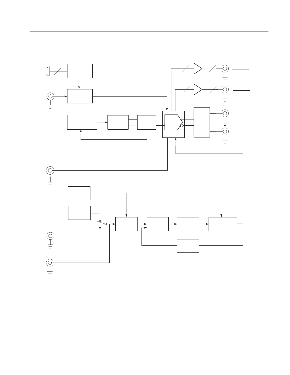
Operating Basics
EXT
EVENT
IN
EXT
TRIG
IN
1/4
CLOCK
OUT
EXT REF
CLOCK
(10 MHz)
4
Event
Control
Tr i g g e r
Control
Memory
Address Control
Frequency
Control
Reference
Oscillator
Wave form
Memory
DDS
Shift
Register
Phase
Comparator
DAC
DAC ASIC
22
22
Analog
Output
Circuit
Loop
Filter
1/2048
Divider
VCO
(Hi/Lo band)
MARKER1
MARKER1
MARKER2
MARKER2
CH1
CH1
Clock
Output
REF
CLOCK
OUT
(10 MHz)
Figure 2-27: AWG710 block diagram
AWG710&AWG710B Arbitrary Waveform Generator User Manual 2-43
Page 90

Operating Basics
Trigger
Control
Event
Control
Address Control
Frequency
Control
Reference
Oscillator
Memory
Wavefor m
Memory
Phase
Comparator
Shift
Register
Analog
Output
Circuit
Clock
Output
Loop
Filter
1/2048
Divider
Figure 2-28: AWG710B block diagram
2-44 AWG710&AWG710B Arbitrary Waveform Generator User Manual
Page 91
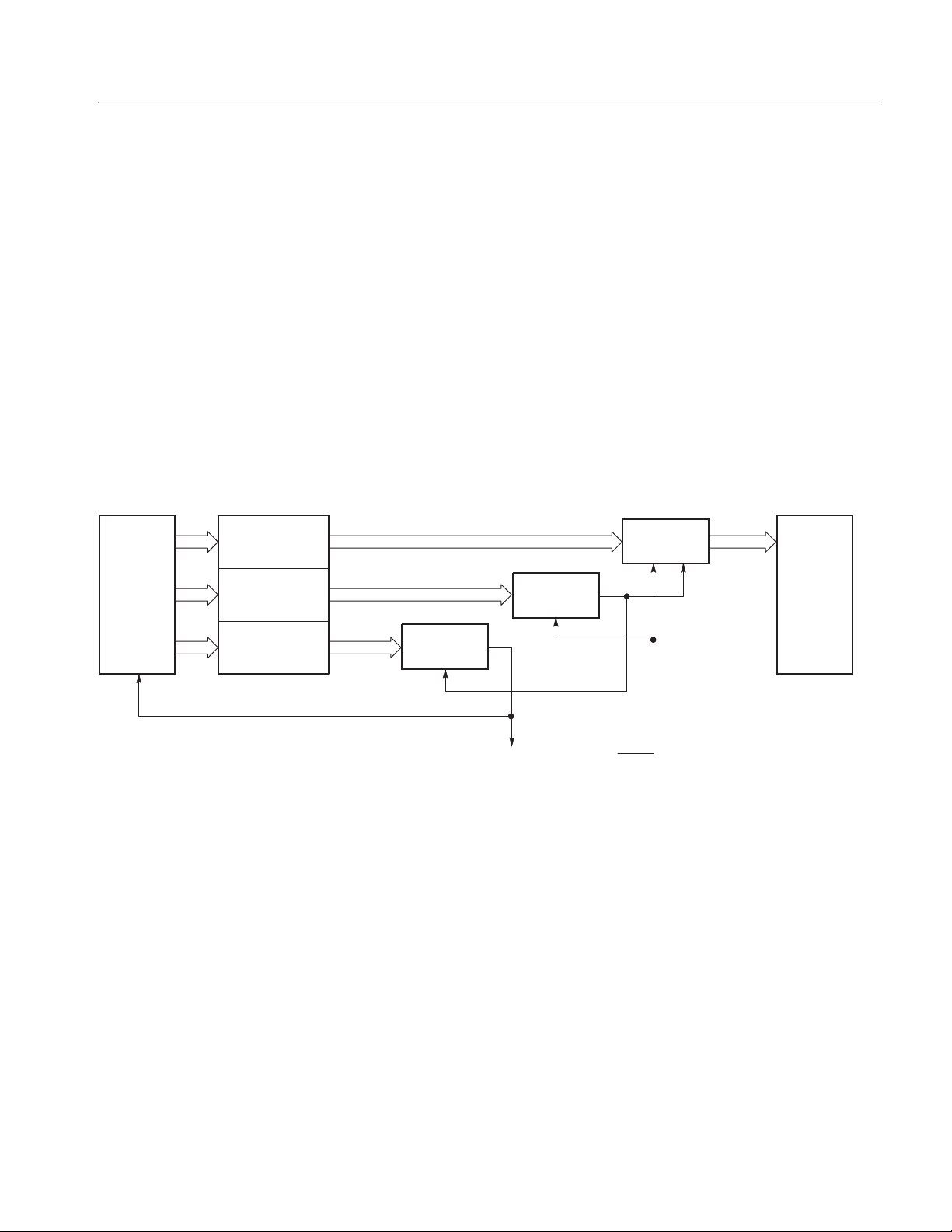
Operating Basics
Memory Address Control. The Memory Address Control controls the addresses
used to read wavef orm memory d ata.
This block loads the first ad dress of the waveform into the Ad dress Counter that
was loaded into the waveform memory. It loads the waveform data length to the
Length Counter. The Address Counter specifies the point from which the
waveform was generated, and the Length Counter waveform ending position.
The Address and Length Counters operate with clocks produced by quarter
frequency–division for the clocks from the clock oscillator.
If the repeat count value has been loaded in the Repeat Counter, the waveform is
generated the specified number of times.
This block controls the sequen ce to the e vent sign als generated in Enhanced Mode.
Start
Address
Sequencer
Wavefor m
length
Repeat
Count
Repeat
Counter
End of Waveform Clock
Length
Counter
Figure 2-29: Relationship between memory address control and waveform memory
Figure 2-29 shows the relationship between the memory address control and the
waveform memory.
Address
Counter
Waveform
Memory
AWG710&AWG710B Arbitrary Waveform Generator User Manual 2-45
Page 92

Operating Basics
Signal Edit Process
This subsection describes the signal edit process.
Load the de sired waveform data to be output into the waveform memory. New
waveform data can be created using waveform editors incorporated in the
AWG710&AWG710B Arbitrary Waveform Generator. New data can also be
created by combining the following:
A sample waveform data distributed with floppy disks.
Previously created waveform data on the built–in hard disk.
Waveform data measured or cr ea ted by other equip ment, which has been read
through the network.
Digital waveform data is loaded to the waveform memory location. The memory
address co ntrol extracts the waveform data from memory, including the clock
speed and the specified order of waveforms relative to the trigger event control.
Waveform Data Structure
When the AWG is in the Running mode, the digital output is processed through a
high speed digital to analog converter (DAC). The output then goes through the
analog output amplifier, to the offset and filter circuitry and to the output
connector.
The waveform data structure consists of analog waveform and digital pattern file
formats. The waveform file format includes 8–bits of resolution for the DAC
output and 2–bits for the digital marker output. The pattern file format includes
10–bits for digital output (The AWG710&AWG710B supports 2 digital marker
outputs). The full –scal e res oluti on of t he 8–bi t DAC is represented by -1 .0 to +1 .0.
Waveform and pattern files use different internal for mats and edi tors. The
wavef orm file format is compo sed of 4–byte litt le en dia n and 1 –byte f or ea ch d ata
point and markers. The 4–bytes point data is expressed as an IEEE floating point
number. The pattern data file is composed of 2–bytes including data and markers.
Waveform files contain floating–point numbers that maintain the mathematical
data precision necessary for waveform math operations such as multiplying,
dividing, adding, subtracting and so forth. Waveform files may be edited, but are
much larger for an equivalent record length compared to pattern files.
Pattern fi les are mos t useful for minimizing f il e size and f ile tr ansfer t ime between
the AWG and a PC.
For more details about file format, refer to Data Transfer section in
AWG710&AWG710B Arbitrary Waveform Generator Programmer Manual.
2-46 AWG710&AWG710B Arbitrary Waveform Generator User Manual
Page 93

Operating Basics
Waveform Edit
To enable editing, the AWG710&AWG710B Arbitrary Waveform Generator
provides you with Waveform, Pattern, Sequence, Equation, and Text Editors. See
Ta ble 2-15 for the explanations of those editors.
Table 2-15: Editors
Editors Descriptions
Waveform Editor The Waveform Editor lets you create or edit a waveform that is being displayed
on the screen. It enables you to create any waveform by an operation such as
cut and paste, partial inversion about the horizontal or vertical axis, shift, or
scaling. This operation can be based on a standard waveform, such as a sine
or rectangular wave, or the previously created waveform.
The Waveform Editor also has a unique feature that is capable of editing a
waveform with waveform calculation functions (absolute value of waveform,
differentiation/integration, convolution, correlation,
addition/subtraction/multiplication between waveforms and so on).
Pattern Editor The Pattern Editor displays a digital signal pattern with a pattern data placed in
8–bit creation waveform memory; it creates a digital signal pattern according to
the High/Low settings you made for the individual bits.
In addition to the functions supported by the Waveform Editor, the Pattern
Editor is capable of generating frequently used digital signals unique to digital
signals and pseudo random patterns.
Sequence Editor The Sequence Editor lets you create a more complex waveform by combining
a few types of the waveform data that you have created using Waveform and/or
Pattern Editors. This editor also enables a Waveform listing jump and output
stop to take place. They follow the external event information from the EVENT
IN connector as well as the number of repetitions and the order for the
individual pieces of waveform data.
Text Editor The Text Editor creates an equation, more exactly, a waveform by a method of
equations. When a equation has been created using this editor, you need to
perform compiling.
The Text Editor also enables you to edit a plain ASCII file. It should be used to
edit ASCII–format waveform data created with another equipment as well as
this instrument itself.
Quick Edit
The Quick Editor lets you modify and/or output any part of a waveform you are
currently editing with the Waveform Editor. This is done in real time. The data
between cursors can be scaled or shifted vertically and/or horizontally
(Expand/Shift).
AWG710&AWG710B Arbitrary Waveform Generator User Manual 2-47
Page 94

Operating Basics
2-48 AWG710&AWG710B Arbitrary Waveform Generator User Manual
Page 95

Tut o rials
This section contains tutorials to help you learn how to operate the
AWG710&AWG710B Arbitrary Waveform Generator. These tutorials provide a
good introduction to the following basic features of the instrument:
Setting up the instrument
Loading and outputting a sample waveform
Creating and editing standard function waveforms
Editing a waveform using quick editor
Using the equation editor
Creating and executing sequences
NOTE. These tutorials do not cover all the features and functions of the
AWG710&AWG710B Arbitrary Waveform Generator. They are intended only to
introduce the basic instrument functions.
By connecting an oscilloscope to the AWG710&AWG710B Arbitrary Waveform
Generator and observing the waveforms output, you will understand how the
AWG710&AWG710B Arbitrary Waveform Generator works. The following
equipment and accessories are needed:
A digital storage oscilloscope
(A Tektronix TDS–Series oscilloscope or equivalent)
One 50 Ω SMA cable
One 50 Ω SMA terminator
One SMA (Fe)–BNC (Ma) adapter
Connect the digital storage oscilloscope to the AWG710&AWG710B Arbitrary
Waveform Generator as shown in Figure 2-30.
NOTE. The CH1 LED is off when a signal is being output from CH1.
If the CH1
LED is on, turn off the output by pushing the CH1 OUT button.
AWG710&AWG710B Arbitrary Waveform Generator User Manual 2-49
Page 96
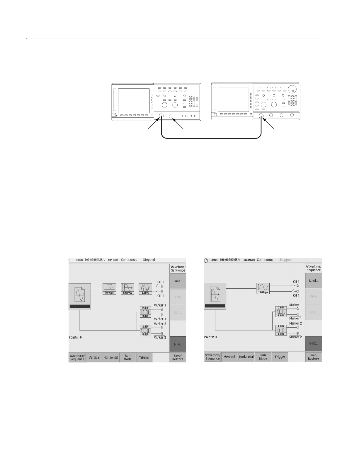
Tutorials
AWG710&AWG710B Arbitrary Waveform Generator TDS-series oscilloscope
CH 1
50Ω SMA Terminator
50Ω SMA coaxial cable
SMA
(Female)-BNC
(Male) adapter
Figure 2-30: Cable connection between AWG710&AWG710B Arbitrary Waveform
Generator and digital storage oscilloscope
Before beginning the tuto rials, confirm that the instr ument is installed correctly.
Refer to Installation on page 1-9.
Push the ON/STBY button to power on the instrument. Refer to Power On on page
1-14. The startup diagn ostic routi nes will run and the instr ument display s an initial
screen similar to that shown in Figure 2-31. You are now ready to perform the
tutorials.
Figure 2-31: Initial screen (Right Figure: option02)
If the instrument does not power on correctly or does not pass the power–on
diagnostics, contact the nearest Tektronix service center for help.
2-50 AWG710&AWG710B Arbitrary Waveform Generator User Manual
Page 97
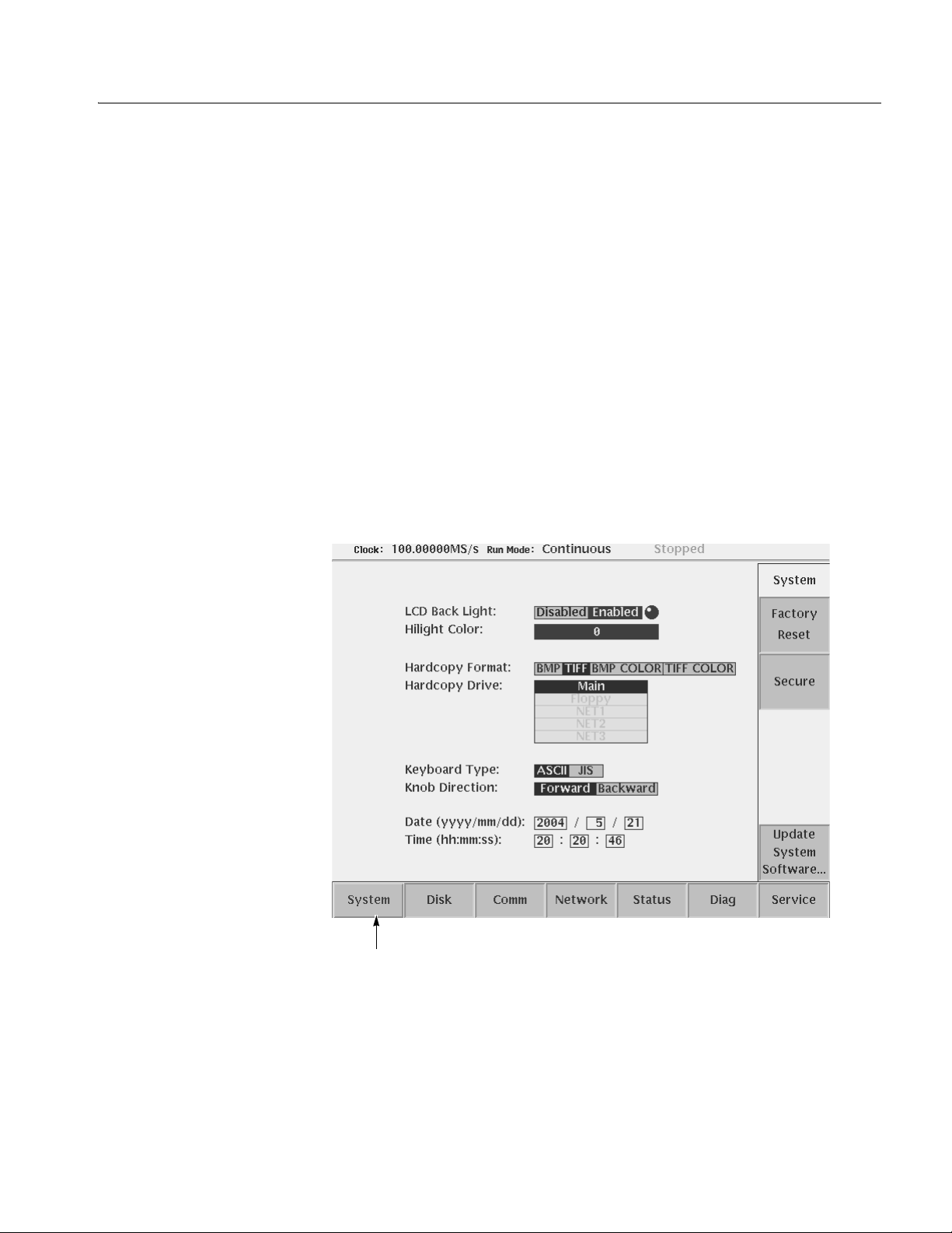
Tutorial 1: Instrument Setup
This tutorial shows you how to do some instrument setups.
In this tutorial you will learn the following:
How to use the arrow button and general purpose knob
How to set the date and time
How to adjust the foc used color
Tutorials
Display the UTILITY Menu
Do the following steps to display the syst em utility screen:
1. Press the UTILITY button on the front–panel to display the UTILITY menu.
2. Press the System bottom button (lower most–left button) on the bezel.
The instrument displays the system utility screen as shown in Figure 2-32.
System is
currently selected
Figure 2-32: System utility screen
AWG710&AWG710B Arbitrary Waveform Generator User Manual 2-51
Page 98

Tutorials
Set the Date and Time
Set the Focused Color
Do the following steps to set the year:
1. Repeatedly press the b button in th e upper middle par t of the f ront panel until
the Year: field is highlighted on the screen.
2. Turn the general purpose knob in the right upper corner of the front panel,
clockwise or counterclockwise until the word year is displayed.
When using the general pur pose knob, note that the cur rent displayed ye ar in the
Year: f ield, is displayed in the upper right corner of the screen with the knob icon.
This means that you can adjust t he value using the gener al purpose knob.
Do the following steps to set the month and day:
1. Press the b button once to highlight the Month:.
2. Use the general purpose knob to set the month.
3. Set the date in the Day: as was done in step 1 and 2 above.
4. Using the b button and the general purpose knob, set the hour, minute and
second in the Hour:, Min : and Sec:, respectively , as were done in step 1 above.
Do the following steps to set th e focused color:
1. Repeatedly press the b button until the Hilight Color: is selected.
LCD Back Light
2. Turn the general purpose kn ob clockwise or counterc lockwise while looking at
the screen until you get the color what you want.
The changes made during this t uto ria l take effect immediately. You can display the
system utility sc reen and a djust the focuse d color at any time without ex iting curr ent
tasks.
You have completed the Instrument Setup tutorial.
The default for the LCD back light is the on state.
Do the following steps to disable the LCD back light:
1. Repeatedly press the b button until the LCD Back Light is highlighted.
2. Press the a button or turn the general purpose knob to the left.
NOTE. The LED display state is saved when you t urn the instrume nt off by p ress ing
the ON / STBY button.
Do the following to turn on the instrument display:
1. Press the ON/STBY button to power on.
2. Press the CLEAR MENU button on the front–panel twice.
You have completed the Instrument Setup tutorial.
2-52 AWG710&AWG710B Arbitrary Waveform Generator User Manual
Page 99

Tutorial 2: Loading and Outputting a Sample Waveform
This tutorial shows you how to load and output a waveform from the sample
waveform floppy disk provided with the AWG710&AWG710B Arbitrary
Waveform Generator.
In this tutorial you will learn the following:
How to select a drive
How to select and load a file
How to view a loaded file
How to output the loaded waveform file
Tutorials
Display the SETUP Menu
Do the following to display the SETUP menu:
Push the SETUP front–panel button to display the SETUP menu screen.
The SETUP menu screen is the initial power–on screen shown in Figure 2-31 on
page 2-50.
Do the following to select a drive:
1. Insert the sample waveform flop py disk into the drive unit to the le ft of the
screen.
2. Push the Waveform/Sequence bottom button to display the
waveform/sequence side menu.
This side menu contains three items: Load..., View, and Edit....
NOTE. The el lipsis (...) means that this menu item will display a submenu (side or
pop–up) when selected.
3. Push the Load... side butt on to display the Select F ile list, shown in
Figure 2-33.
Make sure that the subside menu displays Drive..., Cancel and OK items.
AWG710&AWG710B Arbitrary Waveform Generator User Manual 2-53
Page 100
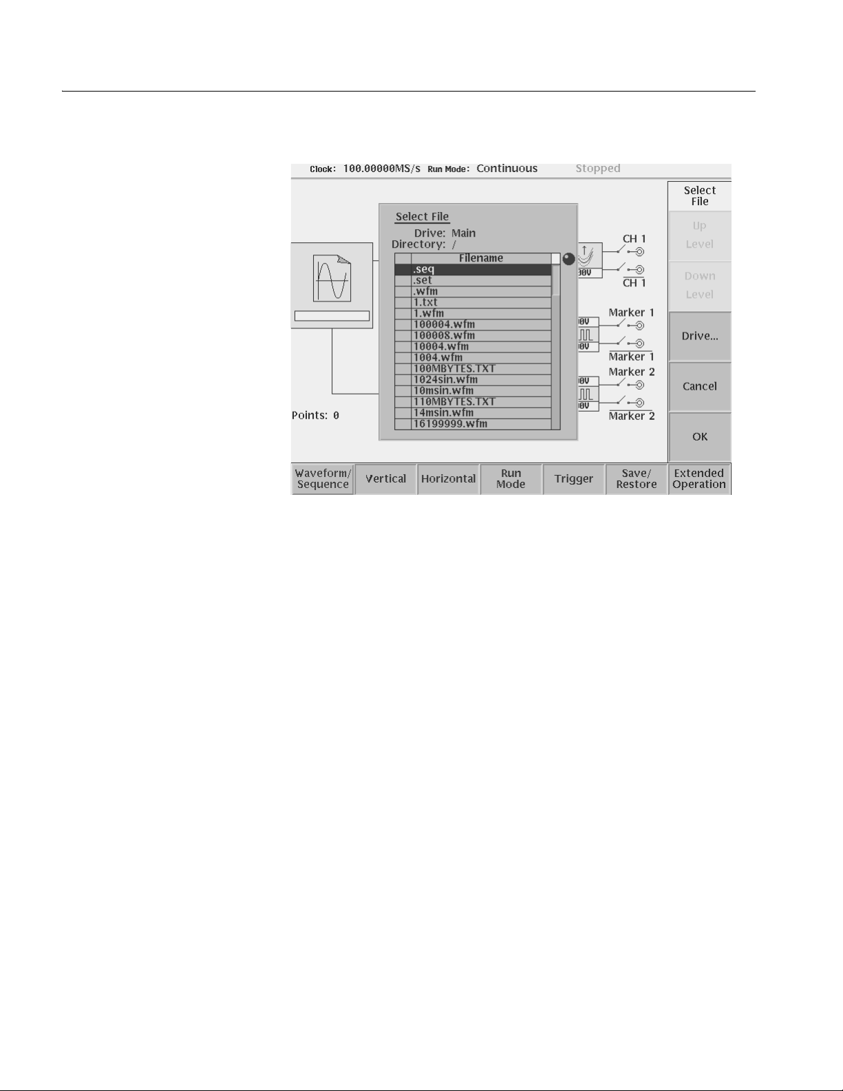
Tutorials
Load a Sample Waveform
Figure 2-33: The Select File list
4. Push the Drive... side menu button.
The Select Drive dialog box appears at the corner of the screen and the Drive...
side menu also appears . Note that the knob icon appears in the dialog box. This
means that you ca n use the ge neral purpo se knob t o sel ect a drive from t he li st.
5. Turn the general purpos e knob or use th e na vigation ar row b uttons to highlight
the word Floppy and then push the OK side button.
The dialog box now lists the files on the sample waveform floppy disk.
Do the following steps to load a sample waveform:
1. Turn the general purpos e knob to sele ct LIN_SWP.WFM from the file listing in
the dialog box.
2. Push the OK side menu button, and wait unti l the LED of the floppy di sk dri ve
goes off.
This operation loads the selected waveform file into the instrument waveform
memory . Confirm that 8000 is displayed in the Points: display f ield at the lo wer left
of the screen and that LIN_SWP.WFM is displayed in the WFM File: di splay field.
2-54 AWG710&AWG710B Arbitrary Waveform Generator User Manual
 Loading...