


xx
AWG7000B and AWG7000C Series
ZZZ
Arbitrary Waveform Generators
Service Manual
www.tektronix.com
P077030503*
*
077-0305-03

Copyright © Tektronix. All rights reserved. Licensed software products are owned by Tektronix or its subsidiaries
or suppliers, and are protected by national copyright laws and international treaty provisions.
Tektronix products are covered by U.S. and foreign patents, issued and pending. Information in this publication
supersedes that in all previously published material. Specifications and price change privileges r eserved.
TEKTRONIX and TEK are registered trademarks of Tektronix, Inc.
Contacting Tektronix
Tektronix, Inc.
14150 SW Karl Braun Drive
P.O . Bo x 50 0
Beaverto
USA
For product information, sales, service, and technical support:
n, OR 97077
In North America, call 1-800-833-9200.
Worl d wide , vis i t www.tektronix.com to find contacts in your area.

Warranty
Tektronix warrants that this product will be free from defects in materials and workmanship for a period of one (1)
year from the date of shipment. If any such product proves defective during this warranty period, Tektronix, at its
option, either will repair the defective product without charge for parts and labor, or will provide a replacement
in exchange for the defective product. Parts, modules and replacement products used by Tektronix for warranty
work may be n
the property of Tektronix.
ew or reconditioned to like new performance. All replaced parts, modules and products become
In order to o
the warranty period and make suitable arrangements for the performance of service. Customer shall be responsible
for packaging and shipping the defective product to the service center designated by Tektronix, with shipping
charges prepaid. Tektronix shall pay for the return of the product to Customer if the shipment is to a location within
the country in which the Tektronix service center is located. Customer shall be responsible for paying all shipping
charges, duties, taxes, and any other charges for products returned to any other locations.
This warranty shall not apply to any defect, failure or damage caused by improper use or improper or inadequate
maintenance and care. Tektronix shall not be obligated to furnish service under this warranty a) to repair damage
result
b) to repair damage resulting from improper use or connection to incompatible equipment; c) to repair any damage
or malfunction caused by the use of non-Tektronix supplies; or d) to service a product that has been modified or
integrated with other products when the effect of such modification or integration increases the time or difficulty
of servicing the product.
THIS WARRANTY IS GIVEN BY TEKTRONIX WITH RESPECT TO THE PRODUCT IN LIEU OF ANY
OTHER WARRANTIES, EXPRESS OR IMPLIED. TEKTRONIX AND ITS VENDORS DISCLAIM ANY
IMPLIED WARRANTIES OF MERCHANTABILITY OR FITNESS FOR A PARTICULAR PURPOSE.
TRONIX' RESPONSIBILITY TO REPAIR OR REPLACE DEFECTIVE PRODUCTS IS THE SOLE
TEK
AND EXCLUSIVE REMEDY PROVIDED TO THE CUSTOMER FOR BREACH OF THIS WARRANTY.
TEKTRONIX AND ITS VENDORS WILL NOT BE LIABLE FOR ANY INDIRECT, SPECIAL, INCIDENTAL,
OR CONSEQUENTIAL DAMAGES IRRESPECTIVE OF WHETHER TEKTRONIX OR THE VENDOR HAS
ADVANCE NOTICE OF THE POSSIBILITY OF SUCH DAMAGES.
[W2 – 15AUG04]
btain service under this warranty, Customer must notify Tektronix of the defect before the expiration of
ing from attempts by personnel other than Tektronix representatives to install, repair or service the product;


Table of Contents
General Safety Summary .......................................................................................... v
Service Safety Summary.................................. ................................ ....................... vii
Environmental Considerations .................................................................................. viii
Preface .............................................................................................................. ix
Manual Conventions........................ ................................ ................................ .. ix
Operating Information ............................................................................................. 1
Theory of Operation............................... ................................ ................................ . 3
Overview .............. .................................. ................................ ....................... 3
Module Overviews ............................................................................................ 6
Adjustment Procedures ........................................................................................... 11
Adjustment Interval........................................................................................... 11
Adjustment After Repair................... .................................. ................................ 11
Required Equipment...................... ................................ .................................. .. 12
Adjustment Overview .............. ................................ ................................ .......... 12
Calibration Procedure .......... ................................ .................................. ............ 15
Maintenance........................................................................................................ 29
Preparation............. .................................. ................................ ...................... 29
Preventing ESD ............................................................................................... 29
Inspection and Cleaning.............................. .................................. ...................... 30
Removal and Installation Procedures.................................... ................................ ........ 34
Preparation............. .................................. ................................ ...................... 34
Summary of Procedures.............................. .................................. ...................... 35
Required Equipment...................... ................................ .................................. .. 36
Disconnecting and Connecting the SMP Cable ........................................................... 37
Procedures for External Modules ........................................................................... 38
Procedures for Internal Modules (Upper) (AWG7000C Series)......................................... 49
Procedures for Internal Modules (Upper) (AWG7000B Series)......................................... 57
Procedures for Internal Modules (Lower).................................................................. 67
Troubleshooting.................................................................................................... 80
Required Equipment...................... ................................ .................................. .. 80
Fault Isolation Procedure .................................................................................... 80
Instrument Diagnostics..................... ................................ ................................ .. 85
Calibration Error .............................................................................................. 92
Hardware Error.............................................................................................. 101
After Repair ..................... ................................ .................................. .......... 103
Returning the Instrument for Service..................................................................... 103
Replaceable Parts................................................................................................ 105
Parts Ordering Information ................................................................................ 105
Using the Replaceable Parts List.......................................................................... 106
AWG7000B and AWG7000C Series Service Manual i

Table of Contents
List of Figure
Figure 1: AWG7000C Series block diagram .................................................................... 4
Figure 2: AWG7000B Series block diagram .................................................................... 5
Figure 3: AwgService UI window ............................................................................... 13
Figure 4: 10 MHz Reference calibration initial test hookup. ... ... . .. . ... ... ... . ... ... ... .. .. . ... ... ... . ... .. 15
Figure 5: 10 MHz Reference Calibration setup window...................... ................................ 16
Figure 6: Inter-channel skew calibration initial hookup .. . ... ... ... ... . ... ... ... . .. . ... ... ... . ... ... ... . ... .. 18
Figure 7: Inter-Channel Skew Calibration setup window..................................................... 19
Figure 8: Interleave calibration ini
Figure 9: Interleave Calibration window ....... .................................. .............................. 23
Figure 10: Magic timing margin check hookup................................................................ 26
Figure 11: Magic Timing Check dialog box.................................................................... 26
Figure 12: Example of good margin and proper timing..................... ................................ .. 27
Figure 13: Example of bad waveform in magic timing margin check....................................... 27
Figure 14: Disassembly procedures for external modules and internal modules (top) ... ... . . .. . ... ... . .. 35
Figure 15: Disassembly procedures for internal modules (bottom).. .................................. ...... 36
Figure 16: Disconnecting and connecting the SMP cable .............................. ...................... 37
Figure 17: Handle, snaps, cosmetic covers, and front-trim unit removal ................................... 39
Figure 18: EMI cover removal....... ................................ .................................. .......... 42
Figure 19: Fan tray unit removal .......................... ................................ ...................... 44
Figure 20: Disassembly of front-panel assembly (AWG7000C Series) ........................... .......... 46
Figure 21: Disassembly of front-panel assembly (AWG7000B Series) ........................... .......... 48
Figure 22: Drive module removal (AWG7000C Series) .......... ................................ ............ 50
Figure 23: Multi-Input/Output board removal (AWG7000C Series) .............. .......................... 51
Figure 24: Processor module removal (AWG7000C Series) ............................... .................. 53
Figure 25: Power Supply and RFI filter removal (AWG7000C Series) ................. .................... 55
Figure 26: Power board removal (AWG7000C Series) ......................... .............................. 56
Figure 27: Drive mo
Figure 28: Multi-Input/Output and Display Adapter board removal (AWG7000B Series) . ... ... . ... ... . 60
Figure 29: Processor module removal (AWG7000B Series) ............................... .................. 63
Figure 30: Power Supply and RFI filter removal (AWG7000B Series) ................. .................... 65
Figure 31: Power board removal (AWG7000B Series) ......................... .............................. 66
Figure 32: Front Connector board, CLK12G module, relay unit, and AWG12G board removal ... ... .. 68
Figure 33: Disassembly of the CLK12G module .............................................................. 70
Figure 34: Relay unit cable connection for option 02 . ................................ ........................ 71
Figure 35: Relay unit cable connection for option 06 . ................................ ........................ 72
Figure 36: Cable ties .............................................................................................. 73
Figure 37: Tie mount clip......................................................................................... 73
Figure 38: Primary troubleshooting tree (1).............................. ................................ ...... 81
s
tial hookup ................................................................. 22
dule removal (AWG7000B Series) .......... ................................ ............ 58
ii AW G7000B and AWG7000C Series Service Manual

Table of Contents
Figure 39: Prim
Figure 40: PWR board test points ....... ................................ .................................. ...... 83
Figure 41: AWG12G board test points.............................. ................................ ............ 84
Figure 42: Diagnostics dialog box............................................................................... 85
Figure 43: Calibration dialog box ............................................................................... 92
Figure 44: Cosmetics............................................................................................ 108
Figure 45: E
Figure 46: AWG7000C Series chassis assembly............. ................................ ................ 110
Figure 47: AWG7000B Series chassis assembly............. ................................ ................ 111
Figure 48: AWG7000C Series front-panel assembly........................................................ 113
Figure 49: AWG7000B Series front-panel assembly........................................................ 115
Figure 50: AWG7000C Series drive modules.............. ................................ .................. 117
Figure 5
Figure 52: AWG7000C Series Processor module............................................................ 121
Figure 53: AWG7000B Series processor module.......................................... .................. 123
Figure 54: AWG7000C Series power supply assembly..................................................... 125
Figure 55: AWG7000B Series power supply assembly..................................................... 127
Figure 56: AWG7000C Series PCI/power interface module ............................................... 129
Figu
Figure 58: Fan tray assembly .............. ................................ .................................. .. 132
Figure 59: USB module......................................................................................... 133
Figure 60: AWG12G/CLK12G/OUT10G modules................................ .......................... 136
Figure 61: CLK12G module ................................................................................... 138
Figure 62: AWG12G module ................................ .................................. ................ 140
Fi
Figure 64: Relay unit............................................................................................ 144
Figure 65: Rear connectors................. .................................. .................................. 146
1: AWG7000B Series drive module. .................................. .............................. 119
re 57: AWG7000B Series PCI/power interface module ............................................... 131
gure 63: SMA bracket .................... ................................ .................................. .. 142
ary troubleshooting tree (2).............. ................................ ...................... 82
MI Covers ......................................................................................... 109
AWG7000B and AWG7000C Series Service Manual iii

Table of Contents
List of Tables
Table 1: Adjustments required for module replaced........... .................................. .............. 11
Table 2: Tes
Table 3: External inspection checklist........................... ................................ ................ 31
Table 4: Internal inspection checklist ....... ................................ ................................ .... 33
Table 5: Tools required for module removal and reinstall .. ................................ .................. 36
Table 6: Power supply voltages.................................................................................. 83
Table 7: PWR board voltages .................................................................................... 84
Table 8: D
Table 9: Calibration error codes ................. ................................ ................................ 92
Table 10: Hardware error codes........................ ................................ ........................ 101
Table 11: Replaceable parts list – cosmetics ........... ................................ ...................... 107
Table 12: Replaceable parts list – EMI covers ......... .................................. .................... 109
Table 13: Replaceable parts list – AWG7000C Series chassis assembly.......... ........................ 110
Table
Table 15: Replaceable parts list – AWG7000C Series front-panel assembly ......... .................... 112
Table 16: Replaceable parts list – AWG7000B Series front-panel assembly ......... .................... 114
Table 17: Replaceable parts list – AWG7000C Series drive modules ....................... .............. 116
Table 18: Replaceable parts list – AWG7000B Series drive module .......................... ............ 118
Table 19: Replaceable parts list – AWG7000C Series Processor module................................. 120
ble 20: Replaceable parts list – AWG7000B Series processor module ................................. 122
Ta
Table 21: Replaceable parts list – AWG7000C series power supply assembly........................... 124
Table 22: Replaceable parts list – AWG7000B series power supply assembly........................... 126
Table 23: Replaceable parts list – AWG7000C Series PCI/power interface module ...... .............. 128
Table 24: Replaceable parts list – AWG7000B Series PCI/power interface module ...... .............. 130
Table 25: Replaceable parts list – fan tray assembly .. ................................ ...................... 132
Table 26: Replaceable parts list – USB module.................................... .......................... 133
Table 27: Replaceable Parts List – AWG12G/CLK12G/OUT10G modules........................ ...... 134
Table 28: Replaceable parts list – CLK12G module .................... ................................ .... 137
Table 29: Replaceable parts list – AWG12G module........................................................ 139
Table 30: Replaceable parts list – SMA bracket ............................................................. 141
Table 31: Replaceable parts list – relay unit.................................................................. 143
Table 32: Replaceable parts list – rear connectors........................................................... 145
t equipment .......................................................................................... 12
iagnostics error codes................................................................................. 86
14: Replaceable parts list – AWG7000B Series chassis assembly.................... .............. 111
iv AW G7000B and AWG7000C Series Service Manual

General Safety Summary
General Safet
To Avoid Fi
re or Personal
Injury
ySummary
Review the fo
this product or any products connected to it.
To avoid pot
Only qualified personnel should perform service procedures.
Use proper
certified for the country of use.
Ground th
of the power cord. To avoid electric shock, the grounding conductor must be
connected to earth ground. Before making connections to the input or output
terminals of the product, ensure that the product is properly grounded.
Observe all terminal ratings. To avoid fire or shock hazard, observe all ratings
and markings on the product. Consult the product manual for further ratings
information before making connections to the product.
Do not apply a potential to any terminal, including the common terminal, that
exceeds the maximum rating of that terminal.
llowing safety precautions to avoid injury and prevent damage to
ential hazards, use this product only as specified.
power cord. Use only the power cord specified for this product and
e product. This product is grounded through the grounding conductor
Power disconnect. The power cord disconnects the product from the power source.
Do not block the power cord; it must remain accessible to the user at all times.
Do not operate without covers. Do not operate this product with covers or panels
removed.
Do not operate with suspected failures. If you suspect that there is damage to this
product, have it inspected by qualified service personnel.
Avoid exposed circuitry. Do not touch exposed connections and components when
power is present.
Do not operate in wet/damp conditions.
Do not operate in an explosive atmosphere.
Keep product surfaces clean and dry.
Provide proper ventilation. Refer to the manual's installation instructions for details
on installing the product so it has proper ventilation.
AWG7000B and AWG7000C Series Service Manual v

General Safety Summary
TermsinThisManual
Symbols and Terms on the
Product
These terms may
WARNING. Warning statements identify conditions or practices that could result
in injury or loss of life.
CAUTION. Caution statements identify conditions or practices that could result in
damage to this product or other property.
These terms may appear on the product:
DANGER in
the marking.
WAR NI NG
read the marking.
CAUTIO
The following symbol(s) may appear on the product:
appear in this manual:
dicates an injury hazard immediately accessible as you read
indicates an injury hazard not immediately accessible as you
N indicates a hazard to property including the product.
vi AWG7000B and AWG7000C Series Service Manual

Service Safety Summary
Service Safet
y Summary
Only qualifie
Safety Summary and the General Safety Summary before performing any service
procedures.
Do Not Service Alone. Do not perform internal service or adjustments of this
product unless another person capable of rendering first aid and resuscitation is
present.
Disconnect Power. To avoid electric shock, switch off the instrument power, then
disconnect the power cord from the mains power.
UseCareWhenServicingWithPowerOn. Dangerousvoltagesorcurrentsmay
exist in
disconnect test leads before removing protective panels, soldering, or replacing
components.
To avoid electric shock, do not touch exposed connections.
d personnel should perform service procedures. Read this Service
this product. Disconnect power, remove battery (if applicable), and
AWG7000B and AWG7000C Series Service Manual vii

Environmental Considerations
Environmenta
Product End-of-Life
Handling
l Considerations
This section
Observe the following guidelines when recycling an instrument or component:
Equipment R
use of natural resources. The equipment may contain substances that could be
harmful to the environment or human health if improperly handled at the product’s
end of life. In order to avoid release of such substances into the environment and
to reduce the use of natural resources, we encourage you to recycle this product
in an appropriate system that will ensure that most of the materials are reused or
recycle
Mercur
mercury. Disposal may b e regulated due to environmental considerations.
Please contact your local a uthorities or, within the United States, the Electronics
Industries Alliance (www.eiae.org) for disposal or recycling information.
provides information about the environmental impact of the product.
ecycling. Production of this equipment required the extraction and
d appropriately.
This symbol indicates that this product complies with the European Union’s
requirements according to Directive 2002/96/EC on waste electrical and
nic equipment (WEEE). For information about recycling options, check
electro
the S upport/Service section of the Tektronix Web site (www.tektronix.com).
yNotification. This product uses an LCD backlight lamp that contains
1
Restriction of Hazardous
bstances
Su
Perchlorate Materials. This product contains one or more type CR lithium
n cell batteries. According to the state of California, CR lithium coin
coi
cells are classified as perchlorate materials and require special handling. See
www.dtsc.ca.gov/hazardouswaste/perchlorate for additional information.
1
The mercury notification applies only to the AWG7000B Series instruments.
This product has been classified as Monitoring and Control equipment, and is
tside the scope of the 2002/95/EC RoHS Directive.
ou
viii AW G7000B and AWG7000C Series Service Manual

Preface
Manual Conventions
This manual contains service information for your instrument. Read this preface
to learn how this manual is structured, the conventions it uses, and where to find
additional s
YoushouldalsoreadtheGeneralandService safety summaries before servicing
the product
upplemental information related to servicing this product.
.
Modules
Replaceable Parts
Safety
This manu
before starting service.
Throughout this manual, any replaceable component, assembly, or part is referred
to by the
assemblies, circuit boards, interconnecting cables, and user-accessible controls.
This manual refers to any field-replaceable assembly or mechanical part
speci
replaceable part is any circuit board or assembly, such as the hard disk drive, or a
mechanical part, such as the I/O port connectors, that is listed in the replaceable
parts list of this manual.
Symbols and terms related to safety appear in the Service Safety Summary at
the beginning of this manual.
al uses certain conventions that you should become familiar with
term module. A module is composed of electrical and mechanical
fically by its name or generically as a replaceable part. In general, a
AWG7000B and AWG7000C Series Service Manual ix

Preface
x AWG7000B and AWG7000C Series Service Manual

Operating Information
For information on installing, operating, and networking the instrument, refer to
the AWG5000 and AWG7000 Series Arbitrary Waveform Generators Quick Start
User Manual.
instrument, and on the Tektronix Web site (www.tektronix.com/manuals).
This manual is available on the Document CD that came with your
AWG7000B and AWG7000C Series Service Manual 1

Operating Information
2 AWG7000B and AWG7000C Series Service Manual

Theory of Operation
This section describes the electrical operation of the AWG7000B and AWG7000C
Series Arbitrary Waveform Generators.
Overview
The Arbitrary Waveform Generators provide various models with different
frequency
the platform and generator. The platform is common to each model.
and numbers of channels. Each model consists of two major sections:
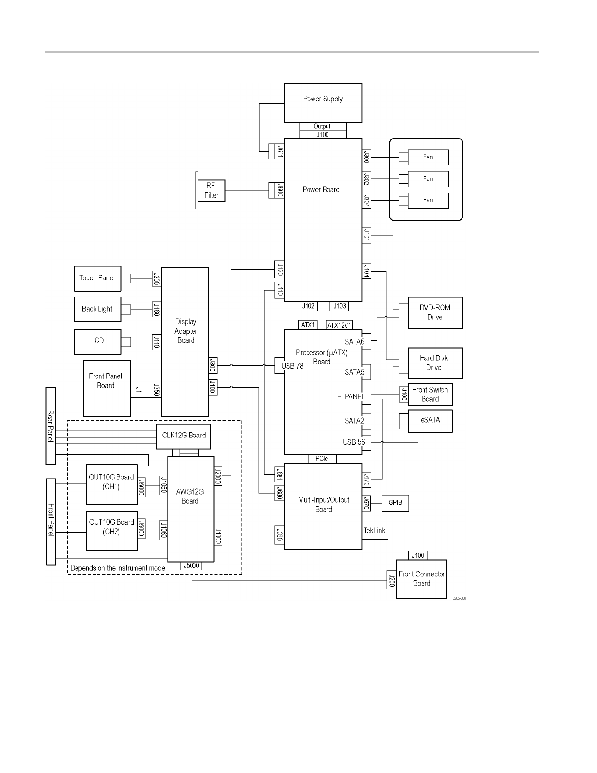
Block Diagram of the
System
The Arbitrary Waveform Generators are based on the μATX CPU board and
componen
operating system. The following figures shows the system-level block diagrams.
ts for a PC. The instrument operates with the Microsoft Window
AWG7000B and AWG7000C Series Service Manual 3
Theory of Operation
Figure 1: AWG7000C Series block diagram
4 AWG7000B and AWG7000C Series Service Manual

Theory of Operation
Figure 2: AWG7000B Series block diagram
AWG7000B and AWG7000C Series Service Manual 5
Theory of Operation
Module Overvi
Front Panel (FP) Board
Display Board
ews
A Microsoft Windows processor system is the primary controller of the
instrument. The instrument features an XGA resolution flat-panel display, a
transparent
instrument functions. You can also make complete use of the instrument with a
mouse and a keyboard.
Push-butt
microcontroller, which sends the button and knob change information to the μAT X
board via a USB path. The FP board consists of the following blocks:
USB controller (Cypress EZ-USB FX1)
FPGA (Al
Key switch matrix
LED indicators (Tri-Color and Mono-Color)
The Display board supports interconnection between the μATX bo a r d a n d F P
board. Two internal USB ports come from the μATX board. One USB connects to
a touch panel controller. The other connects to a microcontroller on the FP board.
Connectors related to the LCD are also included. The Display board consists of
ollowing blocks:
the f
touch screen, and a front panel with direct access to commonly used
on switches on the Front Panel (FP) board are read by an embedded
tera Cyclone)
Touch-panel controller
Rotary encoder (signal goes to the FP board)
Back light controller
Connector to LCD
6 AWG7000B and AWG7000C Series Service Manual
Theory of Operation
Multi-Input/Output (MIO)
Board
The MIO board co
port for AWG7000B series) from various devices that communicate with the
μATX system. The devices include the display system, GPIB, TekLink, and data
flow (PCIF) path to the waveform generator system. An EEROM on this board
stores the instrument settings and calibration data. The MIO board consists of
the following blocks:
PCI controller
GPIB controller
Display controller
NOTE. For AWG7000B Series instruments with serial numbers below B020000,
the ATI Mobility-MI circuit was included in the MIO board. For AWG7000B
Series instruments with serial numbers B020000 and above, a separate display
adapter
For AWG7000C Series instruments, the Processor board provides the video
displa
board (ADD2) performs this function.)
y output.
PCI target adapter
PLD140 (Xilinx FPGA)
ordinates the flow of data through the Windows PCIe port (PCI
Display Adapter (ADD2)
Board (AWG7000B Series)
Front Switch (FSW) Board
Front Connector (FCON)
Board
EEPROM for calibration data storage
TekLink interface
ADD2 board contains LCD display control circuitry that processes video
The
signals from the MIO board.
e Display Adapter board is used with AWG7000B Series instruments serial
Th
numbered B020000 and above. This circuitry formerly resided on the MIO board.
The FSW board provides interconnection between the Standby switch and μAT X
oard. It includes an LED driver.
b
The FCON board provides front-panel connections of the USB ports and the
DC output. It includes common mode filters that suppress EMI radiation on the
USB signal.
AWG7000B and AWG7000C Series Service Manual 7

Theory of Operation
Display Panel
Touch Panel
Processor (μATX) Board
The active-mat
display has a 1024 x 768 resolution and brightness is set to full intensity.
For AWG7000C S
board. For AWG7000B Series instruments, the display is controlled by the MIO
board (or the display adapter board on AWG7000B Series instruments with serial
numbers B020000 and above).
The touch information from the touch screen is processed by Windows drivers,
actively placing the pointer at the touched location. Actions from the mouse
and the touch panel are interchangeable, and treated alike by the user interface
software. The AccuTouch resistive touch screen uses a glass panel with a uniform
resistive coating. A thick polyester coversheet is tightly suspended over the top o f
aglasss
has a hard, durable coating on the outer side and a conductive coating on the inner
side. The controller is located on the LCDA board.
The μAT
on the rear panel. This includes RS-232, Parallel, and Ethernet ports, as well as
four USB ports, plus two USB2.0 ports located in the lower right front corner
of the instrument. The μATX board receives input from the front panel and
touch panel, and implements the appropriate changes. For AWG7000C Series
instruments, video display data is transferred through the LVDS connector. For
7000B Series instruments, video display data is transferred through PCI bus
AWG
interface. The hard drive is connected to the μATX board through the SATA
interface, and the CD/DVD is connected to the Windows system through the
IDE parallel interface.
rix LCD display is fully controlled by Windows drivers. The
eries instruments, t he display is controlled by the Processor
ubstrate, separated by small, transparent insulating dots. The coversheet
X board provides standard Windows functionality and I/O port interfaces
Power Supply
Fans
The CD/DVD drive is connected to the Windows via an interface connector on
the μATX board. AWG7000C Series models connect using the SATA interface.
AWG7000B Series models connect using the IDE parallel interface.
The power supply CVR460 is a switching AC to DC converter. It automatically
detects the line voltage over the range of 90 to 264 VAC. It supplies power to all
the circuitry in the instrument. No switch completely disconnects the line power
from the instrument. The ON/STBY switch controls the power to the instrument
through the μATX board circuitry. When in the “power off” condition, there is still
a low power standby current to allow the system to monitor the ON/STBY switch.
Three fans on the side of the instrument provide forced air cooling. The fans are
controlled by the fan speed control circuit on the PWR board and are regulated by
monitoring the temperature at the circuitry.
8 AWG7000B and AWG7000C Series Service Manual
Theory of Operation
Power (PWR) Board
CLK12G Board
AWG12G
Board
The PWR board pr
MIO board, and AWG12G board. All the power c omes from the CVR460 module.
The fan control circuit ha s a thermal sensor on this board. DC voltage to the fans
is controlled relative to the sensed temperature. DC-DC converters are included
for generating different DC voltages.
The CLK12G board provides a 6 GHz to 12 GHz clock to the AWG12G board.
Two clock outputs go to the CH1 and CH2 DAC. The clock output to CH2 s hould
be terminated for 1 channel models. The clock input accepts 6 GHz to 12 GHz
clock signals from an external signal source. The reference clock input accepts
10 MHz to 8
10 MHz reference output can be used for synchronizing frequency between two or
more instruments. The CLK12G board consists of the following blocks:
YIG oscillator (6 GHz to 12 GHz)
Fractio
10.0 MHz TCXO (reference oscillator)
The AWG12G board generates arbitrary waveforms based on the waveform
memory and the sequence memory. There are two types of PLDs (Xilinx FPGA)
on the board. One is an AWG controller called PLD131, which interfaces to/from
the M
waveform patterns. Waveform data is stored in ZBT type SRAMs. The sequence
memory is included in the memory controller PLD. The AWG12G board consists
of the following blocks:
nal-N PLL
IO board. The other is a memory controller called PLD130 which generates
ovides DC power to the fans, HDD, CD Drive, μATX board,
00 MHz reference clock signals from a n external signal source. The
12 GS/s DAC (HFD205 ASIC)
8 channels 8:1 MUX (TEK0015 ASIC)
D230 (Xilinx Virtex-4 FPGA) as a memory controller
PL
PLD231 (Xilinx Virtex-4 FPGA) as an AWG controller
ZBT type SRAM for the waveform m emory
Inter-channel phase detector
Trigger and event inputs
DC Output
DC-DC converter (1.2 V and 2.5 V power supply)
Dynamic Jump input (AWG7000C Series)
AWG7000B and AWG7000C Series Service Manual 9
Theory of Operation
OUT10G1 Board for
Standard Models
OUT10G2 Board for Option
06 (and Option 02 for
AWG7000
B Series)
The OUT10G1 boa
connector. Amplitude, filter, offset, and On/Off controls are added to the analog
outputs. High/Low voltage and On/Off controls are added to the marker outputs.
The OUT10G1 board consists of the following blocks:
Analog output amplifier
Marker output driver
Selectable
Selectable attenuator
Voltage monitor
Controller PLD
The OUT10G2 board uses the same raw board as the OUT10G1 board. The
difference is that the OUT10G2 board has no analog output circuitry. The analog
signal path is on the relay module. The OUT10G2 board has an analog voltage
monitor. The OUT10G2 board consists of the following blocks:
Marker output driver
Voltage monitor
rd provides analog and marker outputs to the front-panel
low-pass filter
Relay Module (Option
06)(andOption02for
AWG7000B Series)
Coax switch driver
roller PLD
Cont
The relay module provides switches for analog outputs. With Option 06, the
relays switch the interleaving and the analog outputs on and off. An RF power
mbiner is used for mixing channel 1 and 2 signals. The output of the power
co
combiner goes to the Interleave output.
r Option 02, the relays switch the analog outputs on and off.
Fo
10 AW G7000B and AWG7000C Series Service Manual
Adjustment Procedures
This section contains information about instrument adjustment. Only qualified
personnel should perform adjustment procedures. Read the Service Safety
Summary and the General Safety Summary before p erforming any service
procedures.
Adjustment Interval
Adjustment After Repair
NOTE. Befor
e performing adjustment procedures, you must warm up the arbitrary
waveform generator at least 20 minutes in an ambient temperature between 20 °C
and 30 °C. Adjustments performed before warm-up or outside this temperature
range may result in poor performance.
If the instrument fails performance tests (refer to the AWG7000 Series Arbitrary
Wav e for
m Generators Technical Reference Manual), adjustment may be required.
If periodic calibration is one of your requirements, a general rule is to verify
mance and make adjustments (if needed) every 2000 hours of operation (or
perfor
once a y ear if the instrument is used infrequently).
After removal and replacement of a module due to electrical failure, you must
perform the adjustment procedure if the module you replaced is marked “yes”
in the following table. (See Table 1.)
Table 1: Adjustments required for module replaced
Module replaced Adjustment required
Hard disk assembly No
n tray unit
Fa
Front panel assembly No
Drive bay module No
MIO board
isplay Adapter board
D
Processor module No
Power supply No
Power board No
CLK12G module
AWG12G board
OUT10G board
No
Y
N
Yes
Yes
Yes
es
o
AWG7000B and AWG7000C Series Service Manual 11

Adjustment Procedures
Required Equipment
You will need the following equipment:
Table 2: Test equipment
Description Minimum requirements Examples Quantity
Sampling oscilloscope Bandwidth: 20 GHz or higher Tektronix DSA8200 with 80E03
Oscilloscope Bandwidth: 1 GHz or higher Tektronix TDS5104B
Frequency counter Accuracy: within ± 0.01 ppm Agilent 53181A 1 ea
50 Ω BNC cable DC to 2 GHz
50 Ω SMA cable DC to 20 GHz
50 Ω SMA Termination DC to 18 GHz
SMA-BNC adapter SMA female to BNC male
50 Ω SMA Attenuator DC to 18 GHz, 12 dB
Tektronix part number
012-0482-00
Tensolite 1-3636-465-5236 2 ea
Tektronix part number
015-1022-01
Tektronix part number
015-0572-00
Hirose AT-112 2 ea
1ea
1ea
1ea
3ea
2ea
Adjustment Overview
Enable the Service Menu
The adjustment procedure contains up to ten adjustment items, depending on the
ument type and options. Before performing adjustment procedures, you must
instr
warm up the arbitrary waveform generator at least 20 minutes in an ambient
temperature between 20 °C and 30 °C.
You must enable the Service menu to perform the adjustment procedure. To do
this:
1. Power on the instrument.
lect the System menu from the menu bar, and then select Service Mode...
2. Se
3. The following dialog box is displayed. Enter the password “1185”.
12 AW G7000B and AWG7000C Series Service Manual

Adjustment Procedures
4. The AwgService
UI window appears. (See Figure 3.)
Figure 3: AwgService UI window
The left half of the window with the title Calibration is the calibration part of the
window. You can perform the calibrations either all in one step or individually.
ever, since the calibration sequence is predefined, follow the sequence from
How
the top. You must finish a calibration item listed on the upper part of the screen
before performing the lower part of the items. Some items may be grayed out,
depending on your instrument option configurations.
The Data Timing-Magic button is alw ays grayed out because it can be used only
in Factory Mode.
AWG7000B and AWG7000C Series Service Manual 13

Adjustment Procedures
Individual Calibrations
Execute All Calibrations
Saving the Calibration
Results to EEPROM
To perform indi
10MHz Reference..., and the corresponding calibrations are executed.
To perform all calibrations in one step, click Execute All Calibrations and all
calibration
the steps in the data timing calibration, restore and use the calibration constants
obtained by the ATS (Auto Test System) at the factory or during servicing. The
following procedures assume that this method will be used.
When the calibration has been performed and the results are saved to the EEPROM
(regardless of the item, all results are saved to the EEPROM on the MIO board),
the flag under Is Calibrated will be set to TRUE. If the calibration was successful,
the Status field will display PASS. If the calibration failed, FAIL will be displayed.
There are two types of calibration: Self calibration and Manual calibration.
Self calibration - The instrument performs the calibration item and ends
automatically.
Manual calibration - This calibration item requires external test equipment
and manual d ata input. (See Table 2 on page 12.)
A warning message is displayed if you click a calibration button without waiting
for 20 minutes after the instrument powered on. Click the Cancel button and
allow at least 20 minutes for the instrument to warm up.
vidual calibrations, click the calibration buttons, starting with
s are executed in order starting from the top. Instead of performing all
14 AW G7000B and AWG7000C Series Service Manual
Adjustment Procedures
Calibration P
rocedure
Restoring the Calibration
Constants
10 MHz Reference
Calibration
Before starting the calibration procedure, you need to restore the calibration
constants that were obtained by ATS (Automatic Test System) at the factory or
the service c
Click the Copy Calibration Data from AWG12G to MIO button in the middle
right of the Service UI window.
The calibration data saved to the EEPROM on the AWG12G board during the ATS
calibration is restored to the EEPROM on the MIO board. The calibration data on
the MIO bo
This procedure adjusts the built-in TCXO oscillator frequency for the 10 MHz
Referen
Equipment required Prerequisites
One frequency counter
One 50 Ω BNC cable
1. Install the test hookup and preset the instrument controls:
enter.
ard EEPROM is used during the following calibration procedure.
ce Output.
20 minute warm-up at 20 °C to 30 °C
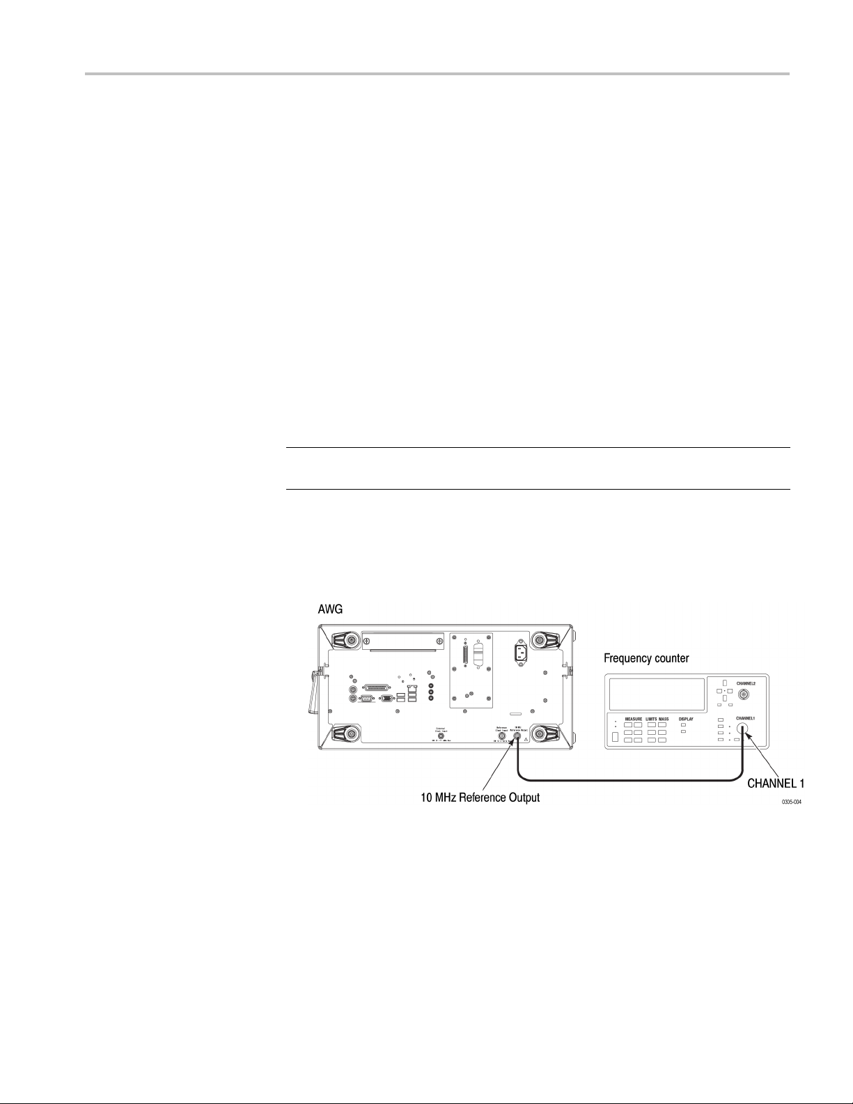
a. Connect a BNC cable from the 10 MHz Reference Output on the rear
panel of the arbitrary waveform generator to the CHANNEL 1 of the
uency counter. (See Figure 4.)
freq
Figure 4: 10 MHz Reference calibration initial test hookup
2. Set the frequency counter CHANNEL 1 Impedance to 50 Ω.
AWG7000B and AWG7000C Series Service Manual 15
Adjustment Procedures
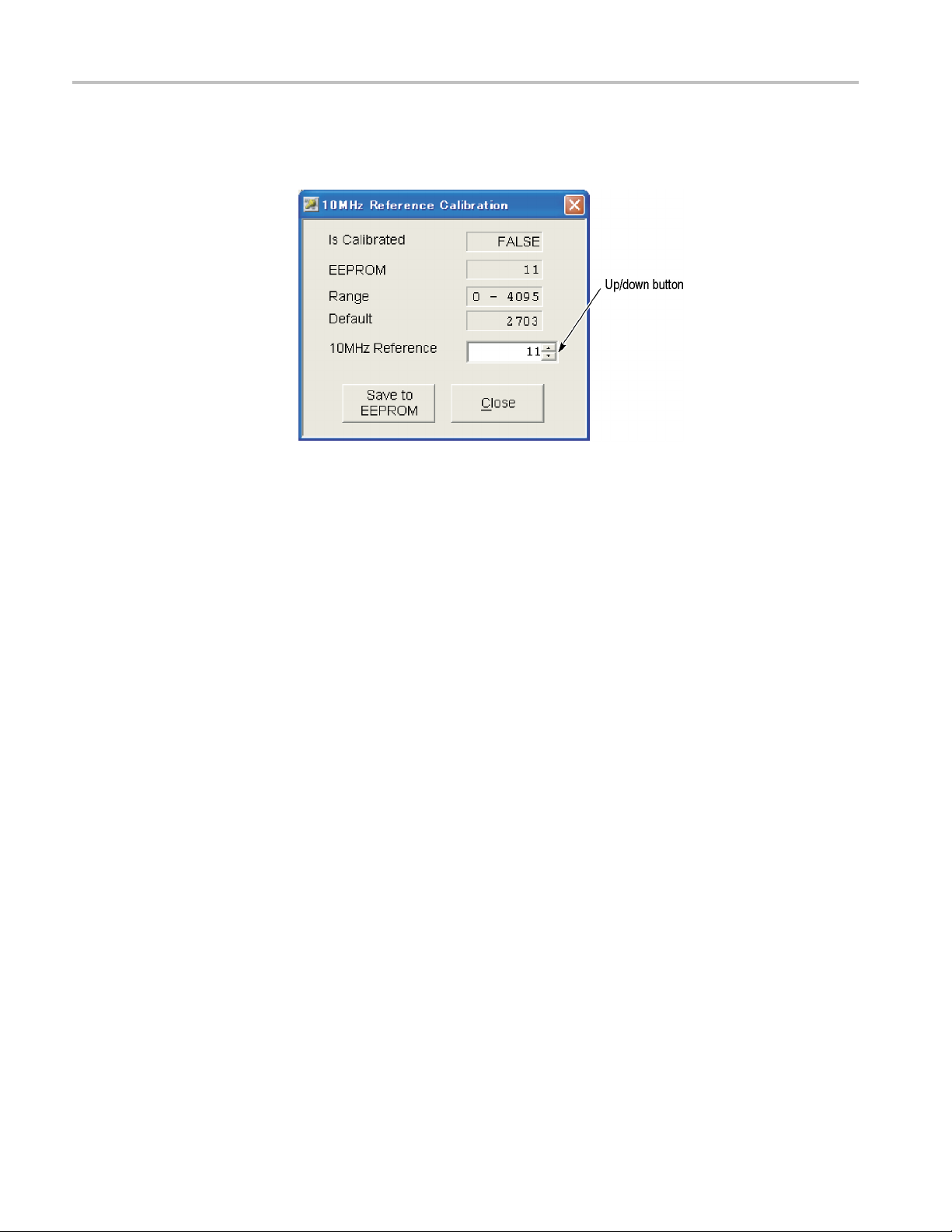
3. Click the 10MHz
display the following setup window:
Figure 5: 10 MHz Reference Calibration setup window
4. Change the 10 MHz Reference value using the up/down button or the
front-panel rotary knob so that the frequency counter reading is within the
range of 10 MHz ±1 Hz.
5. Click Save to EEPROM to save the data to the EEPROM.
Reference... button in the AwgService UI window to
YIG Drive Current
Calibration
Clock Power Calibration
IPC Timing Calibration
6. Click Close to close the window.
This is a self calibration. The YIG for the internal clock source controls the
frequency by the main coil (tuning coil) and the FM coil currents. The sensitivity
differs between individual YIGs, this calibration is required to set the precise
frequency.
This is a s elf calibration. In the instrument, the clock power is need to be
controlled depending on the frequency so that the clock amplitude supplied from
the CLK12G board to the DAC has always the proper value. If you fail to perform
the calibration, the DAC does not work properly, and the AWG12G board may
t work properly.
no
This is a self calibration. The instrument features high-speed communication
called IPC (Inter PLD Communication) between the internal Memory Controller
and the Awg Controller. This calibration ensures the optimum timing to enable
the IPC in all frequency settings. Failing to perform this calibration may disable
access to the waveform memory and/or make the AWG board diagnostics cause
an error.
16 AW G7000B and AWG7000C Series Service Manual

Adjustment Procedures
Data Timing-RAM Timing
Calibration
Data Timing-PLD Timing
Calibration
Analog Output Level
Calibration
Marker O
utput Level
Calibration
Marker Delay Calibration
This is a self ca
the waveform data from the internal RAM to the Memory Controller PLD.
This calibration ensures the optimum timing to enable waveform outputs in all
frequency settings. If you fail to perform the calibration, a waveform data may
not be read from the waveform memory correctly.
This is a self calibration. The instrument outputs a waveform while transferring a
waveform data from the Memory Controller PLD to the ASIC of the following
stage. This calibration ensures the optimum timing to enable waveform outputs
in all frequency settings. If you fail to perform the calibration, a waveform data
cannot be
This is a self calibration. This calibration ensures that the analog output levels
are within the specified range.
This is a self calibration. This calibration ensures that the marker output levels
are within the specified range.
This is a self calibration. This calibration ensures that the marker delay is within
the specified range.
libration. The instrument outputs a waveform while reading
transferred properly, and the waveform may not be output norm ally.
Marker Output Cross Point
Calibration
Inter-Channel Skew
Calibration (AWG7122C,
AWG7082C, AWG7122B,
and AWG7062B)
This is a self calibration. This calibration ensures that the marker output cross
point is within the specified range.
calibration ensures that the Ch 1 and Ch 2 output skews are set within the
This
specified range. This calibration is applied to both analog and marker outputs.
Equipment required Prerequisites
One sampling oscilloscope
Two 50 Ω SMA 12 dB attenuators
Two 50 Ω SMA cables
Three 50 Ω SMA terminations
20 minute warm-up at 20 °C to 30 °C
AWG7000B and AWG7000C Series Service Manual 17

Adjustment Procedures
1. Install the tes
a. Hook up the sampling oscilloscope:
b. Set the sampling oscilloscope as follows:
t hookup and preset the instrument controls:
Attach the SMA terminations to the Channel 1 Analog (–) Output,
Channel 2 Analog (–) Output, and Marker 1 (–) Output on the front
panel of the arbitrary waveform generator.
Connect an SMA cable from the Channel 1 Analog (+) Output on the
front panel of the arbitrary waveform generator to the CH 1 Input of
the sampling oscilloscope using the 12 dB SMA attenuator.
Connect an SMA cable from the Channel 1 Marker 1 (+) Output on
the front panel of the arbitrary waveform generator to the TRIGGER
DIRECT INPUT of the sampling oscilloscope using the 12 dB SMA
attenua
Vertical External Attenuation: 12 dB
Vertical Scale: 200 mV/div
Horizontal Scale: 50 ps/div
Horizontal Timebase Mode: Lock to INT. 10 MHz
tor. (See Figure 6.)
ger: External Direct Input, Level 50%
Trig
Acquisition: Average 64, Stop After Condition: Average Complete
Measurement: R1 to C1 Delay (R1/C1 Reference Level: Absolute
0.0 V)
Figure 6: Inter-channel skew calibration initial hookup
18 AW G7000B and AWG7000C Series Service Manual

Adjustment Procedures
3. Click the Inter
the following setup window:
-Channel Skew... buttonintheServiceUImenutodisplay
Figure 7: Inter-Channel Skew Calibration setup window
4. Perform the following measurements:
a. Adj
b. Disconnect the SMA cable from the Ch 1 Analog (+) Output, and then
c. Push CLEAR DATA and then RUN/STOP on the sampling oscilloscope
AWG7000B and AWG7000C Series Service Manual 19
ust the horizontal position of sampling oscilloscope so that the
rising edge of the arbitrary waveform generator Ch 1 Analog (+) Output
waveform is visible near the center of the oscilloscope screen, and then
select File Menu > Save Waveform... to save the waveform data to R1.
connect it to the Ch 2 Analog (+) Output. Do not use a different cable for
the Ch 1 and Ch 2 connectors. Always use the same SMA cable.
front panel control.

Adjustment Procedures
d. Measure R1 to C1
oscilloscope. Select the following parameters in the Inter-Channel Skew
Calibration window:
SamplingRate:6.0GHz
Ch 2 Phase: 0 °
e. If the delay value measured in step d is outside ±83 ps range, change
the Sampling Rate to 12.0 GHz and then return the setting to 6.0 GHz.
Measure R1 to C1 Delay again. Repeat this measurement until the R1
to C1 Delay value is within the ±83 ps range.
f. Change the parameters as follows in the Inter-Channel Skew Calibration
window:
SamplingRate:6.0GHz
Ch 2 Phase: +180 °
g. Enter the measurement values of R1 to C1 Delay for each setting to the
first place after the decimal point while changing the Ch 2 Phase settings
from +180 degrees to -180 degrees using either the mouse or the Tab key.
Adjust the horizontal position of the sampling oscilloscope as necessary
so that the rising edge of the waveform is displayed at the center of the
screen.
Delay using the Measurement function of the sampling
h. After you complete all the measurements for SamplingRate: 6.0GHz,
click Calc (Delay to Phase). This will display the calculated phase values
in the Ch1– Ch2 Phase (degree) field.
i. Select Sampling Rate: 12.0 GHz.
j. Disconnect the SMA cable from the Ch 2 Analog (+) Output, and then
connectittotheCh1Analog(+)Output.
k. Adjust the horizontal position of the sampling oscilloscope so that the
rising edge of the arbitrary waveform generator Ch 1 Analog (+) Output
waveform is visible near the center of the oscilloscope screen, and
select File Menu > Save Waveform... to save the waveform data to R1.
l. Disconnect the SMA cable from the Ch 1 Analog (+) Output, and then
connectittotheCh2Analog(+)Output.
m. Change the parameters as follows in the Inter-Channel Skew Calibration
window:
Sampling Rate: 12.0 GHz
Ch 2 Phase: +180 degree
n. Enter the measurement values of R1 to C1 Delay for each setting to the
first place after the decimal point while changing the Ch 2 Phase settings
in the order from +180 degrees to -180 degrees using either the mouse or
the Tab key. Adjust the horizontal position of the sampling oscilloscope
then
20 AW G7000B and AWG7000C Series Service Manual

Adjustment Procedures
Interleave Calibration
(AWG7122C, AWG7082C,
and AWG7122B, Option 06
only)
as necessary so
that the rising edge of the waveform is displayed at the
center of the screen.
o. After you comp
lete all the measurements for Sampling Rate: 12.0 GHz,
click Calc (Delay to Phase). This will display the calculated phase values
in the Ch1–Ch2 Phase (degree) field.
5. Click Save to EEPROM.
6. Click Close
. The Inter-Channel Skew Calibration window closes.
This calibration ensures that the phase shift between the Ch 1 analog output and
Ch 2 analog output is exactly 180 degrees at the coupler inputs.
Equipment required Prerequisites
One sampling oscilloscope
One 50 Ω SMA 12 dB attenuator
Two 50 Ω SMA cables
Two 50 Ω SMA terminations
20 minute warm-up at 20 °C to 30 °C
1. Install the test hookup and preset the instrument controls:
a. Hook up the sampling oscilloscope:
Connect an SMA cable from the Interleave (+) Output on the front
panel of the arbitrary waveform generator to the CH 1 Input of the
sampling oscilloscope using the 12 dB SMA attenuator.
Connect an SMA cable from the Channel 1 Marker 1 (+) Output on
the front panel of the arbitrary waveform generator to the TRIGGER
ECT INPUT of the sampling oscilloscope using the 12 dB SMA
DIR
attenuator.
tach the SMA terminations to the Interleave (–) Output and the
At
Channel 1 Marker 1 (–) Output on the front panel of the arbitrary
waveform generator. (See Figure 8 on page 22.)
AWG7000B and AWG7000C Series Service Manual 21

Adjustment Procedures
Figure 8: Interleave calibration initial hookup
b. Set the sampling oscilloscope as follows:
Vertical External Attenuation: 12 dB
Vertical Scale: 100 mV/div
Horizontal Scale: 1 ns/div
Horizontal Timebase Mode: Lock to INT. 10 MHz
er: External Direct Input, Level 50%
Trigg
Acquisition: Average 64
Measurement: C1 High Level, C1 Low Level, R1-Rise to C1-Rise
Delay
2. Click the Interleave... button in the AwgService UI window to display the
Interleave Calibration window. (See Figure 9.)
22 AW G7000B and AWG7000C Series Service Manual

Adjustment Procedures
Figure 9: Interleave Calibration window
3. Click Load Waveform for CH1 PATH in the Interleave Calibration window.
4. On the sampling o scilloscope, use the vertical offset and horizontal position
controls to disp
5. Use the sampling oscilloscope to measure High Level and Low Level for the
signal path from CH1 to Interleave Out. Note the values.
6. Click Load Waveform for CH2 PATH in the Interleave Calibration window.
7. Use the sampling oscilloscope to measure High Level and Low Level for the
signal path from CH2 to Interleave Out. Note the values.
8. On the arbitrary waveform generator, select 12.0 GHz in the Sampling Rate
field, and then click Load Waveform for CH1 PATH in the Interleave
Calibration window.
9. Change the horizontal scale setting on the sampling oscilloscope to 50 ps/div.
10. On the sampling oscilloscope, use the vertical offset and horizontal position
controls to display the waveform at the center of the screen.
11. Save the C1 waveform as R1.
12. Click Load Waveform for CH2 PATH in the Interleave Calibration window.
lay the waveform at the center of the screen.
AWG7000B and AWG7000C Series Service Manual 23

Adjustment Procedures
13. Use the samplin
R1 is the intermediate value between High Level and Low Level values
measured in st
Low Level values measured in step 7.
14. Enter the de
the Interleave Calibration window, and then click Set.
15. Use the up/d
Clock Phase value so that the R1-Rise to C1-Rise Delay value on the
sampling oscilloscope is 41.7 ps ± 2 ps. The target value is displayed on the
middle right of the Interleave Calibration window.
16. In the same way, select the Sampling Rate 11.0 GHz, 10.0 GHz, 9.0 GHz,
8.0GHz,7.0GHz,6.0GHz,andrepeatthemeasurementsdescribedinstep8
through step 15. The target value varies depending on the selected Sampling
Rate.
a. Select 11.0 GHz in the Sampling Rate field, and then repeat the
measurement. The target value is 45.5 ps ± 2 ps.
b. Select 10.0 GHz in the Sampling Rate field, and then repeat the
measurement. The target value is 50.0 ps ± 2 ps.
c. Select 9.0 GHz in the Sampling Rate field, and then repeat the
measurement. The target value is 55.6 ps ± 2 ps.
g oscilloscope to measure R1-Rise to C1-Rise Delay.
ep 5, and C1 is the intermediate value between High Level and
lay value in pico second to the Cal. Value (Skew) entry field in
own button or the front-panel rotary knob to adjust the Ch2
d. Select 8.0 GHz in the Sampling Rate field, and then repeat the
measurement. The target value is 62.5 ps ± 2 ps.
e. Select 7.0 GHz in the Sampling Rate field, and then repeat the
measurement. The target value is 71.4 ps ± 2 ps.
f. Select 6.0 GHz in the Sampling Rate field, and then repeat the
measurement. The target value is 83.3 ps ± 2 ps.
17. Click Update Cal Values.
18. Click Save to EEPROM.
19. Click Close to close the Interleave Calibration window.
24 AW G7000B and AWG7000C Series Service Manual

Adjustment Procedures
Magic Timing Margin
Check
This calibrati
on ensures that high-speed data acquired by DAC (HFD205) have
enough margin and proper timing setting.
NOTE. If any abnormal output waveform is displayed, the instrument must be
returned to Tektronix for calibration. See Contacting Tektronix, following the title
page in this manual, for information on contacting Tektronix Service Support.
Equipment r
One oscillo
Two SMA-BNC adapters
Two 50 Ω SMA cables
Three 50 Ω S
equired
scope
MA terminations
Prerequisi
20 minute wa
tes
rm-upat20°Cto30°C
1. Install the test hookup and preset the instrument controls:
NOTE. The AWG7121B and AWG7061B are single-channel instruments and do
not have a channel 2 output.
a. Hook up the oscilloscope:
Connec
t the SMA cable from the Channel 1 Analog (+) Output on the
front panel of the arbitrary waveform generator to the CH1 Input of
the oscilloscope using the SMA-BNC adapter.
Attach the SMA termination to the Channel 1 Analog (–) Output on
the front panel of the arbitrary waveform generator.
Connect the SMA cable from the Channel 2 Analog (+) Output on the
front panel of the arbitrary waveform generator to the CH2 Input of
the oscilloscope using the SMA-BNC adapter.
Attach the SMA termination to the Channel 2 Analog (–) Output on
the front panel of the arbitrary waveform generator. (See Figure 10.)
b. Set the oscilloscope as follows:
CH1 and CH2 Vertical Scale: 200 mV/div
H1 and CH2 Impedance: 50 Ω
C
Horizontal Scale: 25.0 ns/div
Trigger: Edge Trigger, CH1 Rising, Set Level to 50% (for Ch 1
Analog (+) output)
AWG7000B and AWG7000C Series Service Manual 25

Adjustment Procedures
Trigger: Edge T
Analog (+) output)
Display: Vari
Figure 10: Magic timing margin check hookup
2. Click Magic Timing Margin Check... in the AwgServiceUI window to
display
the Magic Timing Check dialog box.
rigger, CH2 Rising, Set Level to 50% (for Ch 2
able Persistence 500 ms
Figure 11: Magic Timing Check dialog box
3. Set TEK0015 Data Delay Offset to 0 ps, and then verify that a sine wave is
properly displayed on the oscilloscope screen (approximately 1.0 V amplitude
and 85 ns period). Check waveforms for both Channel 1 and Channel 2
Analog outputs.
4. Set TEK0015 Data Delay Offset to 60 ps, and then check that a sine wave is
properly displayed on the oscilloscope screen. Check waveforms for both
Channel 1 and Channel 2 Analog outputs.
5. Set TEK0015 Data Delay Offset to –60 ps, and then check that a sine wave
is properly displayed on the oscilloscope screen. Check waveforms for both
hannel 1 and Channel 2 Analog outputs.
C
26 AW G7000B and AWG7000C Series Service Manual

Figure 12: Example of good margin and proper timing
Adjustment Procedures
Figure 13: Example of bad waveform in magic timing margin check
6. Click Close in the Magic Timing Margin Check dialog box.
ick Exit in the AwgServiceUI window.
7. Cl
This completes the adjustment procedures. Disconnect the equipment from the
nstrument.
i
AWG7000B and AWG7000C Series Service Manual 27

Adjustment Procedures
28 AW G7000B and AWG7000C Series Service Manual

Maintenance
Preparation
This section contains information needed to do periodic and corrective
maintenance on the instrument. The following subsections are included:
Preparation – Tells you how to prepare for arbitrary waveform generator
maintenance.
Preparation Preventing ESD – Provides general information on preventing
damage to internal modules when doing maintenance.
Inspection and Cleaning – Information and procedures for inspecting the
instrument and cleaning its external and internal modules.
Removal and Installation Procedures – Procedures for the removal of
defective modules an
Troubleshooting – Information for isolating failed modules. Included
are instructions for operating the instrument diagnostic routines and
troubleshooting trees. Most of the trees make use of the internal diagnostic
routines to speed fault isolation to a module.
d installation of n ew or repaired modules.
Preventing ESD
Only qualified persons should perform service procedures. Before performing any
service procedures, read the Service Safety Summary and General Safety Summary
at the front of this manual and the ESD information below. Also refer to the
Operating Information section and your arbitrary waveform generator quick start
user manual for information about using the arbitrary waveform generator.
When performing any service that requires internal access to this instrument,
adhere to the following precautions to avoid damaging internal modules and their
components due to electrostatic disch
CAUTION. Static discharge can damage any semiconductor component in this
instrument.
Minimize handling of static-sensitive modules.
Transport and store static-sensitive modules in their static protected containers
or on a metal rail. Label any package that contains static-sensitive modules.
Discharge the static voltage from your body by wearing a grounded antistatic
wrist strap while handling these modules. Service static-sensitive m odules
only at a static-free work station.
arge (ESD).
AWG7000B and AWG7000C Series Service Manual 29

Maintenance
Inspection and Cleaning
Inspection and Cleaning describes h ow to inspect for dirt and damage, and how to
clean the
as preventive maintenance. Preventive maintenance, when done regularly, may
prevent instrument malfunction and enhance its reliability.
Preventive maintenance consists of visually inspecting and cleaning the
instrument and using general care when operating it.
How often to do maintenance depends on the severity of the environment in which
the instrument is used. A proper time to perform preventive maintenance is just
before instrument adjustment.
Do not allow any
work station surface.
Handle circui
Do not slide the modules over any surface.
Avoid handling modules in areas that have a floor or work-surface covering
capable of generating a static charge.
exterior and interior of the instrument. Inspection and cleaning are done
thing capable of generating or holding a static charge on the
t boards by the edges when possible.
General Care
For optimum performance, follow these recommendations:
ect the instrument from adverse weather conditions. The instrument is
Prot
not waterproof.
ot store or leave the instrument where the liquid crystal display (LCD)
Do n
will be exposed to direct sunlight or high humidity for long periods of time.
e cabinet helps keep dust out of the instrument and must be in place during
Th
normal operation.
avoid damage t o the instrument, do not expose it to any sprays, liquids,
To
or solvents.
30 AW G7000B and AWG7000C Series Service Manual

Maintenance
Inspection and Cleaning
procedures
The collection
of dirt on internal components can cause them to overheat and fail.
Dirt also provides an electrical conduction path that could cause an instrument
failure, especially under high-humidity conditions. Inspect the instrument as
often as operating conditions require.
WAR N ING. Before performing any of the following procedures, power down the
instrument and disconnect it from line voltage.
CAUTION. Avoid the use of chemical cleaning agents, which might damage the
plastics used in this instrument. Use only deionized water when cleaning the
front-pa
nel buttons. Use an ethyl alcohol solution as a cleaner and rinse with
deionized water.
Inspection – Exterior. Inspect the outside of the instrument for damage, wear, and
missing parts, using the following table as a guide. An instrument that appears to
have been dropped or otherwise abused should be checked thoroughly to verify
t operation and performance. Immediately repair defects that could cause
correc
personal injury or further damage to the instrument.
Table 3: External inspection checklist
Item Inspect for Repair action
Cabinet, front-panel, and
r
cove
nt-panel knob
Fro
Connectors
rrying handle and cabinet
Ca
feet
ccessories
A
Cracks, scratches,
rmations, damaged
defo
hardware or gaskets.
sing, damaged, or loose
Mis
knob.
ken shells, cracked
Bro
insulation, and deformed
contacts. Dirt in connectors.
rrect operation.
Co
Missing items or parts of
items, bent pins, broken or
rayed cables, and damaged
f
connectors.
Repair or replace defective
le.
modu
air or replace missing or
Rep
defective knob.
Repair or replace defective
modules. Clear or wash out
rt.
di
pair or replace defective
Re
module.
epair or replace damaged
R
or missing items, frayed
cables, and defective
odules.
m
AWG7000B and AWG7000C Series Service Manual 31

Maintenance
Cleaning Proce
exterior:
1. Remove loose d
care to avoid scratching the clear glass display shield.
2. Remove rema
detergent-and-water solution. Do not use abrasive cleaners.
CAUTION. To prevent getting moisture inside the instrument during external
cleaning, use only enough liquid to dampen the cloth or applicator.
NOTE. To avoid damage to the surface of the instrument, do not use any abrasive
or chemical cleaning agents.
Flat Panel Display Cleaning. The display is a soft plastic display and must be
treated with care during cleaning.
CAUTION. Improper cleaning agents or methods can damage the flat panel
display.
dure – Exterior. Do the following steps to clean the instrument
ust on the outside of the instrument with a lint-free cloth. Use
ining dirt with a lint-free cloth dampened in a general purpose
using abrasive cleaners or commercial cleaners to clean the display surface.
Avoid
Avoid spraying liquids on the display surface.
Avoid scrubbing the display with excessive force.
1. Clean the flat panel display surface by gently rubbing the display with a
clean-room wipe (such as Wypall Medium Duty Wipes, #05701, available
from Kimberly-Clark Corporation).
2. If the display is very dirty, moisten the wipe with distilled water or a 75%
isopropyl alcohol solution and gently rub the display surface. Avoid using
xcess force or you may damage the plastic display surface.
e
CAUTION. To prevent getting moisture inside the instrument during external
cleaning, use only enough liquid to dampen the cloth or applicator.
Inspection – Interior. Inspect and clean the interior if it appears that the instrument
may have been damaged or exposed to an unusually dirty environment.
To access the inside of the instrument for inspection and cleaning, refer to the
Removal and Installation Procedures in this section.
32 AW G7000B and AWG7000C Series Service Manual

Maintenance
Inspect the int
ernal portions of the instrument for damage and wear, using the
following table as a guide. Defects should be repaired immediately.
CAUTION. To prevent damage from electrical arcing, ensure that circuit boards
and components are dry before applying power to the instrument.
Table 4: Internal inspection checklist
Item Inspect for Repair action
Front and Rear
Case
Circuit boards
Solder c
Wiring and cables Loose plugs or connectors. Burned,
Chassis Dents, deformations, and damaged
onnections
Cracks or deformations. Scratched
lettering
connectors or labels.
Loose, br
connections. Burned circuit boards.
Burned, broken, or cracked circuit-run
plating.
Cold sol
broken
hardw
or display filter. Loose
oken, or corroded solder
der or rosin joints.
, or frayed wiring.
are.
Repair or replace
defective hardware.
Remove failed module
and replace with a new
module.
Resolder joint and clean
yl alcohol.
with eth
Firmly seat connectors.
or replace
Repair
modules with defective
wires or cables.
Straighten, repair,
lace defective
or rep
hardware.
ning Procedure – Interior. Do the following steps to clean the instrument
Clea
interior:
1. Blo
w off dust with dry, low-pressure, deionized air (approximately 9 p si).
2. Remove any remaining dust with a lint-free cloth dampened in isopropyl
ohol (75% solution) and rinse with warm deionized water. (A cotton-tipped
alc
applicator is useful for cleaning in narrow spaces and on circuit boards.)
NOTE. If steps 1 and 2 do not remove all the dust or dirt, please contact Tektronix.
(See Contacting Tektronix at the front of this manual.)
Lubrication. There is no periodic lubrication required for the instrument.
AWG7000B and AWG7000C Series Service Manual 33

Removal and Installation Procedures
Removal and Installation Procedures
This section contains procedures for removal and installation of all mechanical
and electrical modules.
Preparation
WARNING. Only qualified personnel should perform service procedures.
Before performing this or any other procedure in this manual, read the General
Safety Summary and Service Safety Summary found at the beginning of this
manual. To prevent possible injury to service personnel or damage to the
instrument components, read Preventing ESD in this section.
This section contains the following items:
This preparatory information that you need to properly do the following
procedures.
justment After Repair
Ad
List of Modules
List of tools required to remove and disassemble all modules.
Procedures for removal and reinstallation of the modules.
WARNING. Before doing any procedure in this section, disconnect the power cord
from the line voltage source. Failure to do so could cause serious injury or death.
NOTE. Read Equipment Required for a list of the tools needed to remove and
install modules in this instrument. (See page 36, Required Equipment.) Read the
cleaning procedure before disassembling the instrument for cleaning.
After the removal and replacement of a module due to electrical failure, perform
the adjustment procedures. (See page 11, Adjustment Procedures.)
The Replaceable Parts section provides a list of all replaceable modules.
34 AW G7000B and AWG7000C Series Service Manual

Removal and Installation Procedures
Summary of Pro
cedures
Disassembly for replacement is b est achieved by removing and replacing the
modules in a specific order. Complete disassembly is best achieved by the
following pr
ocedures in the order given in the following figures.
ure 14: Disassembly procedures for external modules and internal modules (top)
Fig
AWG7000B and AWG7000C Series Service Manual 35

Removal and Installation Procedures
Requir
ed Equipment
Figure 15: Disassembly procedures for internal modules (bottom)
Most modules in the instrument can be removed with a screwdriver handle
mounted with a size T-15, Torx screwdriver tip. All equipment required to remove
install the modules is listed in the following table.
and re
Table 5: Tools required for module removal and reinstall
Item # Name Description General Tool #
1.
2. T-15 Torx tip
3. T-10 Torx tip
4. T-20 Torx tip
5.
6.
Screwdriver handle
#1 Phillips screwdriver Screwdriver for removing
#2 Phillips screwdriver Screwdriver for removing
Accepts Torx-driver bits 620-440
Torx-driver bit for T-15 size
screw heads
Torx-driver bit for T-10 size
screw heads
Torx-driver bit for T-20 size
screw heads
#1 size Phillips screws
#2 size Phillips screws
640-247
Standard tool
Standard tool
36 AW G7000B and AWG7000C Series Service Manual

Table 5: Tools required for module removal and reinstall (cont.)
Item # Name Description General Tool #
7.
8. Pliers
9.
10. Angle-Tip Tweezers
11. Wire cutter Used to remove cable ties
3/16 inch open-end
wrench
5/16 inch torque
wrench ( 8.0 in-lbs)
Disconnecting and Connecting the SMP Cable
When you disconnect or connect the SMP cable, use the pliers specified in the
required equipment table and keep the connector vertical. If excessive sideways
force is applied, the connector is damaged.
Removal and Installation Procedures
Used to remove nut posts
Pliers modified for use in SMP
cable insertion/extraction
Used to remove SMA cables
Used to remove the front-panel
knob
Standard tool
003-1895-00
Standard tool
Standard tool
Figure 16: Disconnecting and connecting the SMP cable
AWG7000B and AWG7000C Series Service Manual 37

Removal and Installation Procedures
Procedures fo
Handle Unit
r External Modules
You need a screwdriver with a T-20 Torx tip (items 1 and 4).
Removal. To r
page 39.)
1. Remove the t
cover.
2. Grasp the b
Installation. To install, reverse this procedure.
Snaps
You n eed
Removal. To remove the snaps, follow these steps: (See Figure 17 on page 39.)
1. Remove the four screws securing the snaps to the cosmetic cover.
2. Lift the snaps away from the cosmetic cover.
Installation. To install, reverse this procedure.
a screwdriver with a T-15 Torx tip (items 1 and 2).
emove the handle unit, follow these steps: (See Figure 17 on
wo screws securing the handle base bracket to the cosmetic
racket and handle away from the cosmetic cover.
38 AW G7000B and AWG7000C Series Service Manual

Removal and Installation Procedures
Figure 17: Handle, snaps, cosmetic covers, and front-trim unit removal
AWG7000B and AWG7000C Series Service Manual 39

Removal and Installation Procedures
Cosmetic Cover (Top)
Cosmetic Cover (Bottom)
You n eed a sc rew
Removal. To remove the top cosmetic cover, follow these steps: (See Figure 17
on page 39.)
1. Remove the snaps.
2. Remove the two screws (side) and three screws (top) securing the cosmetic
cover to the chassis.
3. Loosen the cover with a detaching tool, such as a flat-blade screwdriver.
4. Tilt the rear side of the cover up, and then pull it off the chassis.
Installation. To install, reverse this procedure.
You need a screwdriver with a T-15 Torx tip (items 1 and 2).
Removal. To remove the bottom cosmetic cover, follow these steps: (See
Figure 17 on page 39.)
1. Removethehandleunit.
2. Orient the instrument so its top is down on the work surface and its rear is
facing you.
driver with a T-15 Torx tip (items 1 and 2).
3. Remove the two screws (side) and three screws (bottom) securing the
cosmetic cover to the chassis.
4. Loosen the cover with a detaching tool, such as a flat-blade screwdriver.
5. Tilt the rear side of the cover up, and then pull it off the chassis.
Installation. To install, reverse this procedure.
40 AW G7000B and AWG7000C Series Service Manual

Removal and Installation Procedures
Front-Trim Unit
Youneedascrew
and 10).
Removal. To remove the front-trim unit, follow these steps: (See Figure 17 on
page 39.)
1. Remove the handle unit, snaps, and cosmetic covers.
2. Orient the instrument so that the rear is on the work surface.
3. Tape the power switch button down so that it will not come off the front trim.
4. Remove the
angle-tip tweezers.
5. Remove th
6. Grasp the bottom side of the front trim, and pull off the bottom side of it by
looseni
7. The upper part of the chassis has three projections. The front trim fits in
these p
it upward before pulling it forward.
Installation. To install, reverse this procedure.
driver with a T-15 Torx tip, and angle-tip tweezers (items 1, 2,
knob by pulling it straight out from the front panel with the
e three screws at the bottom of the front trim.
ng the DVD drive part.
rojections. When removing the front trim, grasp its back edge and flex
EMI Covers
You need a screwdriver with a T-15 Torx tip (items 1 and 2).
Removal. To remove the EMI covers, follow these steps: (See Figure 18 on
page 42.)
1. Remove the handle unit, snaps, cosmetic covers, and front-trim unit.
2. Remove the top cover:
a. Orient the instrument so that the bottom is on the work surface.
emove the 14 screws securing the top EMI cover to the chassis.
b.R
c. Lift the cover off the chassis.
3. Remove the bottom cover:
a. Orient the instrument so that the top is on the work surface.
b. Remove the 12 screws securing the bottom EMI cover to the chassis.
c. Lift the cover off the chassis.
Installation. To install, reverse this procedure.
AWG7000B and AWG7000C Series Service Manual 41

Removal and Installation Procedures
Figure 18: EMI cover removal
Hard Disk Assembly
42 AW G7000B and AWG7000C Series Service Manual
Removal. To remove the removable hard disk assembly, follow these steps:
1. Orie
2. Loo
3. Ho
nt the instrument so that its bottom is down on the work surface and
its rear is facing you.
sen the two thumb screws securing the hard disk assembly to the
instrument.
lding the screw heads, pull out the removable hard disk assembly carefully.

Removal and Installation Procedures
Fan Tray Unit
Installation.
CAUTION. The hard disk drive is extremely susceptible to static-discharge
damage, shock, dust and so on. When you store a removable hard disk assembly,
put it into an anti-static plastic bag to protect it.
You n eed a screwdriver with a T-15 Torx tip and a #2 Phillips screwdriver (items
1, 2, and 6).
Removal. To remove the fan tray unit, follow these steps: (See Figure 19.)
1. Remove the handle unit, snaps, cosmetic covers, front-trim unit, and EMI
covers.
2. Disconnect the fan cables from J300, J302, and J304 on the Power board.
3. Removethefourscrewssecuringthefantrayunittothechassis.
4. Lift the fan tray unit away from the chassis.
5. Use a #2 Phillips screwdriver to remove the 12 screws securing the fans to
the fan bracket.
To install, reverse this procedure.
Install. To install, reverse this procedure.
AWG7000B and AWG7000C Series Service Manual 43

Removal and Installation Procedures
Front-Panel Unit
Figure 19: Fan tray unit removal
You need a screwdriver with a T-15 Torx tip (items 1 and 2).
Removal. To remove the front-panel unit, follow these steps: (See Figure 20
on page 46.)
1. Remove the handle unit, snaps, cosmetic covers, front-trim unit, and EMI
covers.
2. Orient the instrument so that the rear is on the work surface.
3. Remove the seven screws se curing the front-panel bracket to the chassis.
4. Grasp the front-panel assembly and pull it forward.
5. Disconnect the cable from J100 on the LCDA board.
sconnect the cable from J300 on the LCDA board.
6. Di
Installation. To install, reverse this procedure.
44 AW G7000B and AWG7000C Series Service Manual

Removal and Installation Procedures
Front-Panel Assembly
(AWG7000C Series)
Youneedascrew
Removal. To remove the front-panel assembly, follow these steps: (See Figure 20
on page 46.)
1. Remove the cosmetic covers, front-trim unit, and EMI covers.
2. Remove the Display Adapter board and Front Panel board:
a. Remove the f
Panel board to the front-panel bracket.
b. Remove the
c. Lift the boards away from the front-panel bracket.
3. Remove the display module:
a. Remove the two screws from the touch screen bracket and lift the bracket
away.
b. Remove the four screws securing the display module (touch screen and
LCD) to the front-panel bracket.
c. Disconnect the cable from the FSW board.
d. Disconnect the cable from J200 on the Display Adapter board.
driver with a T-15 Torx tip (items 1 and 2).
our screws securing the Display Adapter board and Front
cables from J110, 500, and J200.
e. Disconnect the cable from J110 on the Display Adapter board.
f. Lift
4. Disassemble the front-panel assembly components, using the following figure
as a
Installation. To install, reverse this procedure.
the display module away from the front-panel bracket.
guide.
AWG7000B and AWG7000C Series Service Manual 45

Removal and Installation Procedures
Figure
20: Disassembly of front-panel assembly (AWG7000C Series)
Front-Panel Assembly
(AWG7
000B Series)
You need a screwdriver with a T-15 Torx tip (items 1 and 2).
Removal. To remove the front-panel assembly, follow these steps: (See Figure 21
on page 48.)
1. Remove the cosmetic covers, front-trim unit, and EMI covers.
2. Rem
ove the LCDA board and Front Panel board:
a. Remove the four screws securing the LCDA board and Front Panel board
the front-panel bracket.
to
b. Remove the cables from J110, J160, and J200.
c. Lift the boards away from the front-panel bracket.
46 AW G7000B and AWG7000C Series Service Manual

Removal and Installation Procedures
3. Remove the touc
a. Remove the two screws securing the touch screen module to the
front-panel b
b. Disconnect the cable from J200 on the LCDA board.
c. Lift the touch screen module away from the front-panel bracket.
4. Remove the LCD module:
a. Remove the four screws securing the LCD module to the front-panel
bracket.
b. Disconnect the cable from J110 on the LCDA board.
c. Disconnect the cable from CN2 on the Inverter board.
d. Lift the
5. Disassemble the front-panel assembly components, using the following figure
as a gui
Installation. To install, reverse this procedure.
de.
h screen module:
racket.
LCD module away from the front-panel bracket.
AWG7000B and AWG7000C Series Service Manual 47

Removal and Installation Procedures
Figure 21: Disassembly of front-panel assembly (AWG7000B Series)
48 AW G7000B and AWG7000C Series Service Manual

Removal and Installation Procedures
Procedures fo
Drive-Bay Module
DVD-R
r Internal Modules (Upper) (AWG7000C Series)
You need a screwdriver with a T-15 Torx tip (items 1 and 2).
emove the drive-bay module, follow these steps: (See Figure 22
e eight screws securing the drive-bay module to the chassis.
OM Drive
Removal. To r
on page 50.)
1. Remove the handle unit, snaps, cosmetic covers, front-trim u nit, EMI covers,
and hard disk assembly.
2. Orient the instrument so that the bottom is on the work surface.
3. Remove th
4. Disconnect the cables from J101 and J104 on the Power board.
5. Disconnect the cables from J5J1 and J7J1 on the Processor board.
6. Lift the drive-bay module away from the chassis.
Installation. To install, reverse this procedure.
You n eed a screwdriver with a T-15 Torx tip and a #1 Phillips screwdriver (items
1, 2, and 5).
val. To remove the DVD-ROM drive, follow these steps: (See Figure 22
Remo
on page 50.)
1. Rem
2. Re
3.S
4. Remove the four screws securing the DVD-ROM drive to the bracket.
Installation. To install, reverse this procedure.
ove the handle unit, snaps, cosmetic covers, front-trim unit, EMI covers,
hard disk assembly, and drive-bay module.
move the two screws securing the DVD-ROM bracket to the drive-bay
chassis.
lide the DVD-ROM drive with bracket out from the drive-bay chassis.
AWG7000B and AWG7000C Series Service Manual 49

Removal and Installation Procedures
Figure 22: Drive module removal (AWG7000C Series)
50 AW G7000B and AWG7000C Series Service Manual

Removal and Installation Procedures
Multi-Input/Output Board
Youneedascrew
Removal. To remove the Multi-Input/Output (MIO) board, follow these steps:
(See Figure 28.)
1. Remove the handle unit, snaps, cosmetic covers, front-trim u nit, EMI covers,
hard disk assembly, and drive-bay module.
2. Orient the instrument so that the bottom is on the work surface and the rear is
facing you.
3. Disconnect the cables from J360, J600, J670, and J680 on the MIO board.
4. Remove the six screws securing the MIO board to the chassis.
5. Carefully pull up on the board to loosen it from the Processor board.
6. Lift the
7. Remove the rear bracket and hardware from the circuit board.
Installation. To install, reverse this procedure.
driver with a T-15 Torx tip (items 1 and 2).
circuit board and pull it through the rear of the chassis.
gure 23: Multi-Input/Output board removal (AWG7000C Series)
Fi
AWG7000B and AWG7000C Series Service Manual 51

Removal and Installation Procedures
Processor Module
You n ee d a s cre w
(items 1, 2, and 7).
NOTE. Before you remove the processor module, you need to disconnect the
ribbon cable at J1000 from the AWG12G board. (See page 73, AWG12G 1 CH
Board (AWG7000B Series Only).) (See page 74, AWG12G 2 CH Board.).
Removal. To remove the processor module, follow these steps: (See Figure 24
on page 53.)
1. Remove the handle unit, snaps, cosmetic covers, front-trim unit, EMI covers,
hard disk assembly, drive-bay module, and Multi-Input/Output board.
2. Orient the instrument so that the bottom is on the work surface.
3. Remove the two screws securing the drive-bay bracket to the processor tray.
4. Lift the drive-bay bracket away from the processor tray. (If necessary, remove
the ribbon cable through the hole on the drive-bay bracket.)
5. Remove the six mounting posts securing the VIDEO connector, COM 1
connector, and PARALLEL PORT connector to the chassis.
6. Remove the eight screws securing the Processor tray to the chassis.
driver with a T-15 Torx tip and a 3/16 inch open-end wrench
7. Disc
8. Carefully lift up and slide the processor module away from the chassis.
Installation. To install, reverse this procedure.
onnect these cables:
The cable from the Power board at ATX1 and ATX12V1.
The cable from the Display Adapter board at USB78.
The cable from the Front Connector board at USB56.
The cable from the Front Switch board and Multi-Input/Output board at
F_PANEL.
The cable from the CD/DVD ROM Drive at SATA6.
The cable from the hard drive at SATA5.
he cable from the eSATA connector at SATA2.
T
The cable from the Synchronization Clock Out connector at J1.
52 AW G7000B and AWG7000C Series Service Manual

Removal and Installation Procedures
Figure 24: Processor module removal (AWG7000C Series)
AWG7000B and AWG7000C Series Service Manual 53

Removal and Installation Procedures
Power Supply
lter
RFI Fi
You n eed a sc rew
Removal. To remove the power supply, follow these steps: (See Figure 25 on
page 55.)
1. Remove the handle unit, snaps, cosmetic covers, front-trim unit, EMI covers,
hard disk assembly, drive-bay module, and Multi-Input/Output board.
2. Orient the instrument so that the bottom is on the work surface.
3. Remove the six screws securing the power supply bracket to the chassis.
4. Disconnect the cable from J611 on the Power board.
5. Remove th
6. Carefully slide the module to loosen it from the Power board.
7. Lift the power supply up out of the chassis.
8. Lift the bracket up out of the chassis.
Installation. To install, reverse this procedure.
You need a screwdriver with a T-15 Torx tip (items 1 and 2).
driver with a T-15 Torx tip (items 1 and 2).
e three screws securing the bracket to the power supply.
Removal. To re m o v e the RFI filter, follow these steps: (See Figure 25 on page 55.)
1. Remove the handle unit, snaps, cosmetic covers, and EMI cove rs.
2. Orient the instrument so that the bottom is on the work surface.
3. Disconnect the cable from J600 on the Power board.
4. Remove the two scre ws securing the ground leads to the chassis.
5. Re
6. Pull the RFI filter away from the chassis.
Installation. To install, reverse this procedure.
move the two screws securing the RFI filter to the chassis.
54 AW G7000B and AWG7000C Series Service Manual

Removal and Installation Procedures
e 25: Power Supply and RFI filter removal (AWG7000C Series)
Figur
AWG7000B and AWG7000C Series Service Manual 55

Removal and Installation Procedures
Power Board
You n eed a sc rew
Removal. To remove the Power board, follow these steps: (See Figure 26 on
page 56.)
1. Remove the handle unit, snaps, cosmetic covers, front-trim unit, EMI covers,
hard disk assembly, drive- bay module, power supply, Multi-Input/Output
board, and Processor board.
2. Orient the instrument so that the bottom is on the work surface.
3. Disconnect the cables from J102, J103, J120, J300, J302, J304, J600, and
J611 on the Power board.
4. Remove the 10 screws securing the Power board to the chassis.
5. Lift the board away from the chassis.
Installation. To install, reverse this procedure.
driver with a T-15 Torx tip (items 1 and 2).
Figure 26: Power board removal (AWG7000C Series)
56 AW G7000B and AWG7000C Series Service Manual

Removal and Installation Procedures
Procedures fo
Drive-Bay Module
DVD-R
r Internal Modules (Upper) (AWG7000B Series)
You need a screwdriver with a T-15 Torx tip (items 1 and 2).
emove the drive-bay module, follow these steps: (See Figure 27
e eight screws securing the drive-bay module to the chassis.
OM Drive
Removal. To r
on page 58.)
1. Remove the handle unit, snaps, cosmetic covers, front-trim u nit, EMI covers,
MIO board enforcement bracket, and hard disk assembly.
2. Orient the instrument so that the bottom is on the work surface.
3. Remove th
4. Disconnect the cables from J101 and J104 on the Power board.
5. Disconnect the cables from J5J1 and J7J1 on the Processor board.
6. Lift the drive-bay module away from the chassis.
Installation. To install, reverse this procedure.
You n eed a screwdriver with a T-15 Torx tip and a #1 Phillips screwdriver (items
1, 2, and 5).
val. To remove the DVD-ROM drive, follow these steps: (See Figure 27
Remo
on page 58.)
1. Rem
2. Re
3.S
4. Remove the four screws securing the DVD-ROM drive to the bracket.
Installation. To install, reverse this procedure.
ove the handle unit, snaps, cosmetic covers, front-trim unit, EMI covers,
MIO board enforcement bracket, hard disk assembly, and drive-bay module.
move the two screws securing the DVD-ROM bracket to the drive-bay
chassis.
lide the DVD-ROM drive with bracket out from the drive-bay chassis.
AWG7000B and AWG7000C Series Service Manual 57

Removal and Installation Procedures
Figure 27: Drive module removal (AWG7000B Series)
58 AW G7000B and AWG7000C Series Service Manual

Removal and Installation Procedures
DVD-ROM Board
Multi-Input/Output Board
(Serial Numbers B010000
to B019999)
Youneeda#1Phi
Removal. To remove the DVD-ROM board, follow these steps: (See Figure 27
on page 58.)
1. Remove the handle unit, snaps, cosmetic cover, front-trim unit, EMI covers,
MIO board enforcement bracket, hard disk assembly, and drive-bay module.
2. Remove the two screws securing the DVD-ROM board to the DVD-ROM
drive.
3. Disconnect the cable from J1 on the DVD-ROM board.
4. Disconnect the interface cable on the DVD-ROM board.
5. Lift the b
Installation. To install, reverse this procedure.
You n ee
Removal. To remove the Multi-Input/Output board, follow these steps: (See
Figure 28 on page 60.)
d a screwdriver with a T-15 Torx tip (items 1 and 2).
llips screwdriver (item 5).
oard away from the DVD-ROM drive.
1. Remove the handle unit, snaps, cosmetic covers, front-trim u nit, EMI covers,
MIO board enforcement bracket, hard disk assembly, and drive-bay module.
2. Orient the instrument so that the bottom is on the work surface and the rear is
facing you.
3. Disconnect the cables from J360, J670, J680, and J681 on the
Multi-Input/Output board.
4. Remove the screws securing the Multi-Input/Output board to the chassis.
5. Carefully pull up on the board to loosen it from the Processor board.
ift the circuit board and pull it through the rear of the chassis.
6.L
7. Remove the rear bracket and hardware from the circuit board.
Installation. To install, reverse this procedure.
AWG7000B and AWG7000C Series Service Manual 59

Removal and Installation Procedures
Multi-Input/Output Board
al Numbers B020000
(Seri
and Higher)
Figure 28: Multi-Input/Output and Display Adapter board removal (AWG7000B
s)
Serie
You need a screwdriver with a T-15 Torx tip (items 1 and 2).
Removal. To remove the Multi-Input/Output board, follow these steps: (See
Figure 28.)
1. Remove the handle unit, snaps, cosmetic covers, front-trim unit, EMI covers,
MIO board enforcement bracket, hard disk assembly, and drive-bay module.
2. Orient the instrument so that the bottom is on the work surface and the rear is
facing you.
3. Disconnect the cables from J360, J600, J610, and J680 on the
Multi-Input/Output board.
4. Remove the screws securing the Multi-Input/Output board to the chassis.
5. Carefully pull up on the board to loosen it from the Processor board.
60 AW G7000B and AWG7000C Series Service Manual

Removal and Installation Procedures
Display Adapter (Serial
Numbers B02
0000 and
Higher)
6. Lift the circui
7. Remove the rear bracket and hardware from the circuit board.
Installation. To install, reverse this procedure.
You need a screwdriver with a T-15 Torx tip (items 1 and 2).
Removal. To remove the Display Adapter board (ADD2 board), follow these
steps: (See Figure 28 on page 60.)
1. Remove the handle unit, snaps, cosmetic covers, front-trim u nit, EMI covers,
MIO board enforcement bracket, hard disk assembly, and drive-bay module.
2. Orient the instrument so that the bottom is on the work surface and the rear is
facing you.
3. Remove the two T-15 screws from the support bracket on the ADD2 board.
4. Discon
5. Carefully pull up on the board to loosen it from the Processor board.
6. Lift the circuit board out of the chassis.
t board and pull it through the rear of the chassis.
nect the two cables from the ADD2 board.
allation. To install, reverse this procedure.
Inst
AWG7000B and AWG7000C Series Service Manual 61

Removal and Installation Procedures
Processor Module
You n ee d a s cre w
(items 1, 2, and 7).
NOTE. Before you remove the processor module, you need to disconnect the
ribbon cable at J1000 from the AWG12G board. (See page 73, AWG12G 1 CH
Board (AWG7000B Series Only).) (See page 74, AWG12G 2 CH Board.).
Removal. To remove the processor module, follow these steps: (See Figure 29
on page 63.)
1. Remove the handle unit, snaps, cosmetic covers, front-trim unit, EMI covers,
MIO board enforcement bracket, hard disk a ssembly, drive-bay module, and
Multi-Input/Output board.
2. Orient the instrument so that the bottom is on the work surface.
3. Remove the two screws securing the drive-bay bracket to the processor tray.
4. Lift the drive-bay bracket away from the proc essor tray.
5. Remove the three screws securing the connector bracket to the rear pane l .
6. Lift t
he connector bracket away from the rear panel.
driver with a T-15 Torx tip and a 3/16 inch open-end wrench
7. Remove the six mounting posts securing the VIDEO connector, COM 1
ector, and PARALLEL PORT connector to the chassis.
conn
8. Remove the eight screws securing the Processor tray to the chassis.
9. Disconnect these cables:
The cable from the Power board at J2A1, J2A2, and J2J1.
The cable from the LCDA board at J8H1.
The cable from the Front Connector board at J8G2.
he cable from the Front Switch board and Multi-Input/Output board
T
at J8J3.
arefully lift up and slide the processor module away from the chassis.
10.C
Installation. To install, reverse this procedure.
62 AW G7000B and AWG7000C Series Service Manual

Removal and Installation Procedures
Figure 29: Processor module removal (AWG7000B Series)
AWG7000B and AWG7000C Series Service Manual 63

Removal and Installation Procedures
Power Supply
You n eed a sc rew
Removal. To remove the power supply, follow these steps: (See Figure 30 on
page 65.)
1. Remove the handle unit, snaps, cosmetic covers, front-trim unit, EMI covers,
MIO board enforcement bracket, hard disk a ssembly, drive-bay module, and
Multi-Input/Output board.
2. Orient the instrument so that the bottom is on the work surface.
3. Remove the four screws securing the power supply support bracket.
4. Remove the power supply support bracket from the power supply bracket.
5. Remove the six screws securing the power supply bracket to the chassis.
6. Disconn
7. Remove the three screws securing the bracket to the power supply.
8. Carefully slide the module to loosen it from the Power board.
9. Lift the power supply up out of the chassis.
10. Lift the bracket up out of the chassis.
driver with a T-15 Torx tip (items 1 and 2).
ect the cable from J611 on the Power board.
RFI Filter
Installation. To install, reverse this procedure.
You need a screwdriver with a T-15 Torx tip (items 1 and 2).
Removal. To re m o v e the RFI filter, follow these steps: (See Figure 30 on page 65.)
1. Remove the handle unit, snaps, cosmetic covers, and EMI cove rs.
2. Orient the instrument so that the bottom is on the work surface.
3. Disconnect the cable from J600 on the Power board.
emove the two screws securing the ground leads to the chassis.
4.R
5. Remove the two screws securing the RFI filter to the chassis.
6. Pull the RFI filter away from the chassis.
Installation. To install, reverse this procedure.
64 AW G7000B and AWG7000C Series Service Manual

Removal and Installation Procedures
Figure 30: Power Supply and RFI filter removal (AWG7000B Series)
AWG7000B and AWG7000C Series Service Manual 65

Removal and Installation Procedures
Power Board
You n eed a sc rew
Removal. To remove the Power board, follow these steps: (See Figure 31 on
page 66.)
1. Remove the handle unit, snaps, cosmetic covers, front-trim unit, EMI covers,
MIO board enforcement bracket, h ard disk assembly, drive- bay module,
power supply, Multi-Input/Output board, and Processor board.
2. Orient the instrument so that the bottom is on the work surface.
3. Disconnect the cables from J102, J103, J120, J300, J302, J304, J600, and
J611 on the Power board.
4. Remove the 10 screws securing the Power board to the chassis.
5. Lift the board away from the chassis.
Installation. To install, reverse this procedure.
driver with a T-15 Torx tip (items 1 and 2).
Figure 31: Power board removal (AWG7000B Series)
66 AW G7000B and AWG7000C Series Service Manual

Removal and Installation Procedures
Procedures fo
Front Connector Board
r Internal Modules (Lower)
You need a screwdriver with a T-15 Torx tip (items 1 and 2).
Removal. To r
Figure 32 on page 68.)
1. Remove the h
covers.
2. Orient the
3. Disconnect the cables from J100 and J200 on the Front Connector board.
4. Remove the screw securing the Front Connector board to the chassis.
5. Grasp the board and pull it gently away from the chassis.
Installation. To install, reverse this procedure.
emove the Front Connector board, follow these steps: (See
andle unit, snaps, cosmetic covers, front-trim unit, and EMI
instrument so that the top is on the work surface.
AWG7000B and AWG7000C Series Service Manual 67

Removal and Installation Procedures
Figure 32: Front Connector board, C LK12G module, relay unit, and AWG12G board removal
68 AW G7000B and AWG7000C Series Service Manual

Removal and Installation Procedures
CLK12G Module
Youneedascrew
(items 1, 2, 8, and 9).
Removal. To remove the CLK12G module, follow these steps: (See Figure 32
on page 68.)
1. Remove the handle unit, snaps, cosmetic covers, front-trim unit, and EMI
covers.
2. Orient the instrument so that the top is on the work surface.
3. Disconnect the cable from J150A (and J150B for 2 channel models) on the
AWG12G board.
4. Disconnect the cables from the 10 MHz Reference Output connector and
the Reference Clock Input connector.
5. Use a 5/16 inch torque wrench to remove the External Clock Input connector
from the rear panel.
6. Remove the four screws securing the CLK12G module to the chassis.
7. Carefully pull up on the module to loosen it from the AWG board.
8. Lift t
he module away from the chassis.
driver with a T-15 Torx tip, pliers, and a 5/16 inch torque wrench
CLK12G Board
Installation. To install, reverse this procedure.
eed a #1 Phillips screwdriver and a 5/16 inch torque wrench (items 5 and 9).
You n
Removal. To remove the CLK12G board, follow these steps: (See Figure 33
on page 70.)
1. Remove the five screws securing the shield cover to the top shield cas e.
2. Lift the shield cover away from the top shield case.
isconnect the cables from J3320 and J3350 (and J3351 for 2 channel
3.D
models) on the CLK12G board.
4. Use a 5/16 inch torque wrench to remove the two SMA cables from J3110 and
J3120 on the CLK12G board.
5. Remove the 10 screws securing the top shield case to the bottom shield case.
6. Lift the top shield case away from the bottom shield case.
7. Lift the CLK12G board away from the bottom shield case.
Installation. To install, reverse this procedure.
AWG7000B and AWG7000C Series Service Manual 69

Removal and Installation Procedures
re 33: Disassembly of the CLK12G module
Figu
70 AW G7000B and AWG7000C Series Service Manual

Removal and Installation Procedures
Relay Unit (for Option 02)
(AWG7000B Series Only)
Youneedascrew
1, 2, and 9).
Removal. To remove the relay unit, follow these steps: (See Figure 32 on
page 68.)
1. Remove the handle unit, snaps, cosmetic covers, front-trim unit, and EMI
covers.
2. Orient the instrument so that the top is on the work surface.
3. Use a 5/16 inch torque wrench to remove the six SMA cables (or 12 SMA
cables for 2 channel models) from the relay units.
4. Disconnect the cable (or two cables for 2 channel models) from the relay units.
5. Remove the 10 screws securing the relay unit to the chassis.
6. Lift the relay unit away from the chassis.
Installation. To install, reverse this procedure. (See Figure 34.)
driver with a T-15 Torx tip and a 5/16 inch torque wrench (items
Figure 34: Relay unit cable connection for option 02
Relay Unit (for Option 06)
AWG7000B and AWG7000C Series Service Manual 71
You need a screwdriver with a T-15 Torx tip and a 5/16 inch torque wrench (items
1, 2, and 9).
Removal. To remove the relay unit, follow these steps: (See Figure 32 on
page 68.)
1. Remove the handle unit, snaps, cosmetic covers, front-trim unit, EMI covers.
2. Orient the instrument so that the top is on the work surface.

Removal and Installation Procedures
3. Use a 5/16 inch t
units.
4. Disconnect th
5. Remove the 10 screws securing the relay unit to the chassis.
6. Lift the relay unit away from the chassis.
Installati
on. To install, reverse this procedure. (See Figure 36.)
orque wrench to remove the 14 SMA cables from the relay
e four c ables from the relay units.
Figure 35: Relay unit cable connection for option 06
72 AW G7000B and AWG7000C Series Service Manual

Removal and Installation Procedures
AWG12G1CHBoard
(AWG7000B Series Only)
Youneedascrew
Removal. To remove the AWG12G 1 channel board, follow these steps: (See
Figure 32 on page 68.)
1. Remove the handle unit, snaps, cosmetic covers, front-trim u nit, EMI covers,
CLK12G module, and relay unit (for Option 02).
2. Orient the instrument so that the top is on the work surface.
3. Use a wire cutter to remove the two cable ties.
driver with a T-15 Torx tip and pliers (items 1, 2, and 8).
Figure 36: Cable ties
4. Remove the two screws, and then remove the tie mount clips.
Figure 37: Tie mount clip
AWG7000B and AWG7000C Series Service Manual 73

Removal and Installation Procedures
5. Remove the two c
6. Disconnect the ribbon cables at J 1050, J2000, and J5000 from the AWG12G
board.
7. Disconnect these cables:
The cable at J115A from the AWG12G board to the CH1 OUT10G board
(J150).
The cable at J116A from the AWG12G board to the CH1 OUT10G board
(J170).
The cable at J1430 from the AWG12G board to the Trigger Input
connector.
The cable at J1440 from the AWG12G board to the Event Input connector.
The cables from J100, J110, J600, and J700 on the CH1 OUT10G board.
8. Remove the 9 screws securing the AWG12G board to the chassis.
9. Cut two zip-ties to expose the screws.
10. Remove the two screws, and then remove the hexagon post.
11. Lift th
e board away from the chassis.
able posts.
AWG12G 2 CH Board
12. Disconnect the ribbon cable at J1000 on the AWG12G board.
13. Disconnect these cables:
The cable at J110A from the AWG12G board to the CH1 OUT10G board
(J100).
The cable at J111A from the AWG12G board to the CH1 OUT10G board
(J110).
The cable at J100A from the AWG12G board to the CH1 OUT10G board
(J600).
The cable at J101A from the AWG12G board to the CH1 OUT10G board
(J700).
Installation. To install, reverse this procedure.
You n eed a screwdriver with a T-15 Torx tip and pliers (items 1, 2, and 8).
Removal. To remove the AWG12G 2 channel board, follow these steps: (See
Figure 32 on page 68.)
1. Remove the handle unit, snaps, cosmetic covers, front-trim unit, EMI covers,
CLK12G module, and relay unit (for Option 02 or 06).
2. Orient the instrument so that the top is on the work surface.
74 AW G7000B and AWG7000C Series Service Manual

Removal and Installation Procedures
3. Use a wire cutte
4. Remove the two screws, tie mount clips, and cable posts. (See Figure 37
on page 73.)
5. Disconnect the ribbon cables at J1050, J2000, and J5000 from the AWG12G
board.
6. Disconnect these cables:
The cable at J115A from the AWG12G board to the CH1 OUT10G board
(J150).
The cable at J116A from the AWG12G board to the CH1 OUT10G board
(J170).
The cable at J115B from the AWG12G board to the CH2 OUT10G board
(J150).
The cable at J116B from the AWG12G board to the CH2 OUT10G board
(J170).
The cable at J1430 from the AWG12G board to the Trigger Input
connector.
The cable at J1440 from the AWG12G board to the Event Input connector.
The cables from J100, J110, J600, and J700 on the CH1 OUT10G board.
r to remove the two cable ties. (See Figure 36 on page 73.)
The cables from J100, J110, J600, and J700 on the CH2 OUT10G board.
7. Use a wire cutter to remove the cable tie securing the Dynamic Jump In
cable and disconnect it from J1600. The Dynamic Jump In is only available
on the AWG7000C Series.
8. Remove the 11 screws securing the AWG12G board to the chassis.
9. Lift the board away from the chassis.
10. Disconnect the ribbon cable at J1000 on the AWG12G board.
11. Disconnect these cables:
The cable at J110A from the AWG1
(J100).
The cable at J111A from the AWG12G board to the CH1 OUT10G board
(J110).
The cable at J100A from the AWG12G board to the CH1 OUT10G board
(J600).
The cable at J101A from the AWG12G board to the CH1 OUT10G board
(J700).
The cable at J110B from the AWG12G board to the CH2 OUT10G board
(J100).
2G board to the CH1 OUT10G board
AWG7000B and AWG7000C Series Service Manual 75

Removal and Installation Procedures
CH1 OUT10G Board
The cable at J11
(J110).
The cable at J100B from the AWG12G board to the CH2 OUT10G board
(J600).
The cable at J101B from the AWG12G board to the CH2 OUT10G board
(J700).
Installation. To install, reverse this procedure.
You n eed a screwdriver with a T-15 Torx tip and pliers (items 1, 2, and 8).
Removal. To remove the CH1 OUT10G board, follow these steps: (See Figure 32
on page 68.)
1. Remove the handle unit, snaps, cosmetic covers, front-trim unit, EMI covers,
relay unit (for Option 02 or 06), and AWG12G board.
2. Orient the instrument so that the top is on the work surface.
3. Remove the five screws securing the shield bracket to the chassis.
4. Lift the bracket away from the chassis.
5. Disconnect the ribbon cable at J500 from the CH1 OUT10G board.
1B from the AWG12G board to the CH 2 OUT10G board
6. Disconnect these cables:
NOTE. For Option 02 or 06, there are no cable connections at J600 and J700
on the CH1 OUT10G board.
The cable at J600 from the CH1 OUT10G board to the AWG12G board
(J100A).
The cable at J700 from the CH1 OUT10G board to the AWG12G board
(J101A).
The cable at J100 from the CH1 OUT10G board to the AWG12G board
(J110A).
The cable at J110 from the CH1 OUT10G board to the AWG12G bo
(J111A).
The cable at J150 from the CH1 OUT10G board to the AWG12G board
(J115A).
The cable at J170 from the CH1 OUT10G board to the AWG12G board
(J116A).
The cable at J690 from the CH1 OUT10G board to the Channel 1 Analog
connector.
ard
76 AW G7000B and AWG7000C Series Service Manual

Removal and Installation Procedures
The cable at J79
connector.
The cable at J1
1 connector.
The cable at
1 connector.
The cable at
2 connector.
The cable a
2 connector.
7. Remove th
8. Lift the board away from the chassis.
Installation. To install, reverse this procedure.
e four screws securing the CH1 OUT10G board to the chassis.
0 from the CH1 OUT10G board to the Channel 1 Analog
20 from the CH1 OUT10G board to the Channel 1 Mkr
J130 from the CH1 OUT10G board to the Channel 1 Mkr
J160 from the CH1 OUT10G board to the Channel 1 Mkr
t J190 from the CH1 OUT10G board to the Channel 1 Mkr
AWG7000B and AWG7000C Series Service Manual 77

Removal and Installation Procedures
CH2 OUT10G Board
You need a screw
Removal. To remove the CH2 OUT10G board, follow these steps: (See Figure 32
on page 68.)
1. Remove the handle unit, snaps, cosmetic covers, front-trim unit, EMI covers,
relay unit (for Option 02 or 06), and AWG12G board.
2. Orient the instrument so that the top is on the work surface.
3. Remove the five screws securing the shield bracket to the chassis.
4. Lift the br
5. Disconnect the ribbon cable at J500 from the CH2 OUT10G board.
6. Disconnect these cables:
NOTE. For Option 02 or 06, there are no cable connections at J600 and J700
on the C
H2 OUT10G board.
The cable at J600 from the CH2 OUT10G board to the AWG12G board
(J100B).
The cable at J700 from the CH2 OUT10G board to the AWG12G board
(J101B).
driver with a T-15 Torx tip and pliers (items 1, 2, and 8).
acket away from the chassis.
The cable at J100 from the CH2 OUT10G board to the AWG12G board
(J110B).
The cable at J110 from the CH2 OUT10G board to the AWG12G board
(J111B).
The cable at J150 from the CH2 OUT10G board to the AWG12G board
(J115B).
The cable at J170 from the CH2 OUT10G board to the AWG12G board
(J116B).
The cable at J690 from the CH2 OUT10G board to the Channel 2 Analog
connector.
The cable at J790 from the CH2 OUT10G board to the Channel 2 Analog
connector.
78 AW G7000B and AWG7000C Series Service Manual

Removal and Installation Procedures
The cable at J12
1 connector.
The cable at J1
1 connector.
The cable at
1 connector.
The cable at
1 connector.
7. Remove the
8. Lift the board away from the chassis.
Installation. To install, reverse this procedure.
four screws securing the CH2 OUT10G board to the chassis.
0 from the CH2 OUT10G board to the Channel 2 Mkr
30 from the CH2 OUT10G board to the Channel 2 Mkr
J160 from the CH2 OUT10G board to the Channel 2 Mkr
J190 from the CH2 OUT10G board to the Channel 2 Mkr
AWG7000B and AWG7000C Series Service Manual 79

Troubleshooting
Troubleshooting
WARNING. To prevent possible injury to service personnel or damage to electrical
components,
WARNING. Before performing this or any other procedure in this manual, read the
General Saf
this manual.
This section contains information and procedures designed to help you isolate
faults to a module.
This section requires that service personnel have the appropriate skills to work on
this instrument, including PC troubleshooting and Microsoft Windows operating
system skills. Details of PC and Windows operation and service are not in this
manual
For assistance, contact your local Tektronix Service Center.
please read Preventing ESD on (See page 29, Preventing ESD.).
ety Summary and Service Safety Summary found at the beginning of
.
Required Equipment
You will need a digital multimeter to check power supply voltages, as described
on (S
Fault Isolation Procedure
Fol
isolation.
ee page 83, Checking the Power Supply Voltages.).
low the primary troubleshooting tree on the following two pages for fault
80 AW G7000B and AWG7000C Series Service Manual

Troubleshooting
Figure 38: Primary troubleshooting tree (1)
AWG7000B and AWG7000C Series Service Manual 81

Troubleshooting
Figure 39: Primary troubleshooting tree (2)
82 AW G7000B and AWG7000C Series Service Manual

Troubleshooting
Checking the Power
Supply Voltages
To check the pow
er supply voltages, power on the instrument and connect the (–)
lead of a multimeter to chassis ground.
To measure the
output voltages of the power supply, check the voltages at J104
on the PWR board with the multimeter and compare each reading to the values
listed in the following table. If the voltages are within the allowance, your power
supply is functional.
Figure 40: PWR board test points
Table 6: Power supply voltages
PWR board (J104) Voltage Allowance
Pin1 +3.3 V +3.1 V to +3.5 V
Pin 3 +5 V +4.7 V to 5.3 V
Pin 5 +12 V +11.4 V to +12.6 V
AWG7000B and AWG7000C Series Service Manual 83

Troubleshooting
Checking the PWR Board
Voltages
To measure the o
utput voltages of the PWR board, check the voltages at J2000
on the AWG12G board with the multimeter and compare each reading to the
values listed in the following table. If the voltages are within the allowance,
your PWR board is functional.
Figure 41: AWG12G board test points
7: PWR board voltages
Table
AWG12G board (J2000) Voltage Allowance
Pin 1 +12 V +11.
Pin 5 +3.3 V +3.1 V to +3.5 V
Pin 12 -5 V -4.7 to -5.4 V
13
Pin
Pin 14 +8 V +7.6 V to +8.4 V
Pin 17 +5 V +4.7 V to +5.3 V
n23
Pi
+15
-8
V
V
4Vto+12.6V
.2 V to +15.8 V
+14
.6 to -8.4 V
-7
84 AW G7000B and AWG7000C Series Service Manual

Instrument Diagnostics
Troubleshooting
The primary diagnostics for the instrument are accessible through the AWG
application software. The Instrument diagnostics check the basic functionality
of analog and marker output at every power on. The Instrument Diagnostics run
after Windows has booted up and run its own set of system checks. If any failures
occur at pow
provides an error code:
Diagnostics error codes (See Table 8 on page 86.)
Calibration error codes (See Table 9 on page 92.)
Hardware error codes (See Table 10 on page 101.)
The power-on tests ensure that the hardware is installed and can be accessed
by the software. The tests provide limited diagnostic information, and provide
no performance information.
To run the instrument Diagnostics manually, do these steps:
1. Turn off all other applications.
er on, a pop-up message indicates that a failure has occurred and
2. From the menu bar, select System andthenselectDiagnostics...;the
Diagnostics dialog box appears. (See Figure 42.)
Figure 42: Diagnostics dialog box
AWG7000B and AWG7000C Series Service Manual 85

Troubleshooting
Table 8: Diagno
Error code Error log message
120000000
120000001
120000002
120000003
120000004
1200000
120000006
120000007
120000008
1200
120
12
120000012
121000000
05
00009
000010
0000011
stics error codes
HwDiagAwgRegister AwgController address_0x21
register dia
HwDiagAwgR
register diag. Fail expected data=xxxx actual data=xxxx
HwDiagAwgRegister AwgController address_0x30
register diag. Fail expected data=xxxx actual data=xxxx
HwDiagAwgRegister AwgController address_0x40
register
HwDiagAw
register diag. Fail expected data=xxxx actual data=xxxx
HwDiagAwgRegister AwgController address_0x42
register diag. Fail expected data=xxxx actual data=xxxx
HwDiagAwgRegister AwgController address_0x50
regist
HwDiag
Communication Fail expected data=xxxx actual
data=xxxx -N:PLD no
HwDiagAwgRegister Ch2 MemoryController-N
Comm
data=xxxx -N:PLD no
HwDiagAwgRegister Ch1 TEK0015-TNO address_REG
register diag. Fail expected data=xxxx actual data=xxxx
TNO
HwDiagAwgRegister Ch2TEK0015-TNO address_REG
register diag. Fail expected data=xxxx actual data=xxxx
O: TEK0015 number REG: Register number
TN
HwDiagAwgRegister Ch1 HFD205 address_REG
register diag. Fail expected data=xxxx actual data=xxxx
EG: Register number
R
wDiagAwgRegister Ch2 HFD205 address_REG
H
register diag. Fail expected data=xxxx actual data=xxxx
REG: Register number
HwDiagWaveformMemory channel=1,
MemoryController-P Data bus Error RAM/PLD-pinName
expected data=xxxxxxxx actual data=xxxxxxxx
P:PLD number RAM/PLD-pinName:U5x0–yy-pinRam /
U400zz-pinPld
g. Fail expected data=xxxx actual data=xxxx
egister AwgController address_0x23
diag. Fail expected data=xxxx actual data=xxxx
gRegister AwgController address_0x41
er diag. Fail expected data=xxxx actual data=xxxx
AwgRegister Ch1 MemoryController-N
unication Fail expected data=xxxx actual
: TEK0015 number REG: Register number
Possible defect
on board Note
AWG12G AWG12G: U1000
AWG12G AWG12G: U10
AWG12G AWG12G: U1000
AWG12G AWG12G: U1000
AWG12G AWG12G: U
AWG12G AWG12G: U1000
AWG12G AWG12G: U1000
AWG12G
U1000
AWG12G:
U100
AWG12G:
U1000
AWG12G:
U1000
AWG12G AWG12G: U1000, U100A
A
AWG12G
:
0
WG12G
N=0 -> U
N=2 -> U400RA N =3 -> U400SA
N=4 -> U400TA
N=0 -> U400PB N=1 -> U400QB
> U400RB N=3 -> U400SB
N=2 N=4 -> U400TB
TNO=0 -> U300PA TNO=1 ->
U300QA TNO=2 -> U300RA
=3 -> U300SA TNO=4 ->
TNO
U300TA
TNO=0 -> U300PB TNO=1 ->
U300QB TNO=2 -> U300RB
O=3 -> U300SB TNO=4 ->
TN
U300TB
WG12G: U1000, U100B
A
P=0 -> U400PA, U500PA, U510PA
P=1 -> U400QA, U500QA, U510QA
P=2 -> U400RA , U500RA, U510RA
P=3 -> U400SA, U500SA, U510SA
P=4 -> U400TA, U500TA, U510TA
00
1000
400PA N=1 -> U400QA
86 AW G7000B and AWG7000C Series Service Manual
 Loading...