

Page 1

xx
AWG5000B and AWG7000B Series
Arbitrary Waveform Generators
ZZZ
Quick Start User Manual
www.tektronix.com
071-2481-00
Page 2

Copyright © Tektronix. All rights reserved. Licensed software products are owned by Tektronix or its subsidiaries or suppliers, and are
protected by na
tional copyright laws and international treaty provisions.
Tektronix prod
previously published material. Specifications and price change privileges reserved.
TEKTRONIX and TEK are registered trademarks of Tektronix, Inc.
ucts are covered by U.S. and foreign patents, issued and pending. Information in this publication supersedes that in all
Contacting Tektronix
Tektronix, Inc.
14200 SW Karl Braun Drive
P.O. Box 500
Beaverton, OR 97077
USA
For product information, sales, service, and technical support:
In North America, call 1-800-833-9200.
Worldwide, visit www.tektronix.com to find contacts in your area.
Page 3

Warranty 2
Tektronix warrants that this product will be free from defects in materials and workmanship for a period of one (1) year from the date of
shipment. If any such product proves defective during this warranty period, Tektronix, at its option, either will repair the defective
product without charge for parts and labor, or will provide a replacement in exchange for the defective product. Parts, modules and
replacement products used by Tektronix for warranty work may be new or reconditioned to like new performance. All replaced
parts, modules and products become the property of Tektronix.
In order to obtain service under this warranty, Customer must notify Tektronix of the defect before the expiration of the warranty period
and make suitable arrangements for the performance of service. Customer shall be responsible for packaging and shipping the
defective product to the service center designated by Tektronix, with shipping charges prepaid. Tektronix shall pay for the return of the
product to Customer if the shipment is to a location within the country in which the Tektronix service center is located. Customer shall
be responsible for paying all shipping charges, duties, taxes, and any other charges for products returned to any other locations.
This warranty shall not apply to any defect, failure or damage caused by improper use or improper or inadequate m aintenance and
care. Tektronix shall not be obligated to furnish service under this warranty a) to repair damage resulting from attempts by personnel
other than Tektronix representatives to install, repair or service the product; b) to repair damage resulting from improper use or
connection to incompatible equipment; c) to repair any damage or malfunction caused by the use of non-Tektronix supplies; or
d) to service a product that has been modified or integrated with other products when the effect of such modification or integration
increases the time or difficulty of servicing the product.
THIS WARRANTY IS GIVEN BY TEKTRONIX WITH RESPECT TO THE PRODUCT IN LIEU OF ANY OTHER WARRANTIES,
EXPRESS OR IMPLIED. TEKTRONIX AND ITS VENDORS DISCLAIM ANY IMPLIED WARRANTIES OF MERCHANTABILITY OR
FITNESS FOR A PARTICULAR PURPOSE. TEKTRONIX’ RESPONSIBILITY TO REPAIR OR REPLACE DEFECTIVE PRODUCTS
IS THE SOLE AND E XCLU S IVE REMEDY PROVIDED TO THE CUSTOMER FOR BREACH OF THIS WARRANTY. TEKT RONIX
AND ITS VENDORS WILL NOT BE LIABLE FOR ANY INDIRECT, SPECIAL, INCIDENTAL, OR CONSEQUENTIAL DAMAGES
IRRESPECTIVE OF WHETHER TEKTRONIX OR THE VENDOR HAS ADVANCE NOTICE OF THE POSSIBILITY OF SUCH
DAMAGES.
Page 4

Page 5

Table of Contents
General Safety Summary .. . ... . .. . ... . . .. . ... ... . .. . ... . .. . ... . .. . ... ... . ... . . .. . ... ... . .. . ... . .. . ... . .. . ... ... . ... ... . .. . ... . .. . .... iii
Environmental Considerations........................................................................................................ v
Preface................................................................................................................................. vi
Key Features .....................................................................................................................vi
Documentation .................................................................................................................. vii
Conventions Used in this Manual . ... . .. . ... . .. . ... . .. . ... . .. . ... . .. . ... . .. . ... . .. . ... . .. . ... . .. . ... . .. . ... . .. . ... . .. . ... . .. . .. vii
Installing YourInstrument ............................................................................................................. 1
Standard Accessories. ... . ... ... . .. . ... . .. . ... . .. . ... . .. . ... .. .. . ... ... . ... ... . .. . ... . ... ... . .. . ... . .. . ... . .. . ... . .. . ... . . .. . ... . 1
Operating Requirements . . .. . ... ... . ... ... . .. . ... . ... ... . .. . ... . .. . ... . .. . ... . .. . ... . . .. . ... ... . ... . . .. . ... ... . ... ... . .. . ... . ... . 2
Powering On the Instrument..................................................................................................... 3
Powering Off the Instrument..................................................................................................... 3
Windows Interface Guidelines . . ... . .. . ... . .. . ... . .. . ... . .. . ... . . .. . ... . .. . ... . . .. . ... . .. . ... . . .. . ... . .. . ... . . .. . ... . .. . ... . . .. . . 4
Connecting to a Network. . ... . .. . ... . . .. . ... ... . ... ... . .. . ... . .. . ... . .. . ... . . .. . ... ... . ... ... . .. . ... . .. . ... . .. . ... . . .. . ... ... . .. . 4
Setting GPIB/LAN ................................................................................................................ 5
Controlling the InstrumentUsing a Remote PC................................................................................. 6
Offline Mode...................................................................................................................... 6
Inspecting YourInstrument ...................................................................................................... 7
Self Calibration ................................................................................................................... 8
Preventing Instrument Damage ................................................................................................. 9
OptionInstallation............................................................................................................... 10
Creating Operating System Restore CD-ROMs..................................................................................... 11
Creating Restore CD-ROMs.................................................................................................... 11
Restoring the Instrument Operating System................................................................................... 12
Front Panel.. . .. . ... . .. . ... . .. . ... . .. . ... . ... ... . ... ... . .. . ... . ... ... . ... . . .. . ... . .. . ... . .. . ... . .. . ... . .. . ... . .. . ... . ... ... . ... ........ 13
Rear Panel (AWG7000 Series) .. . ... ... . ... . .. . ... . ... ... . ... . .. . ... . ... ... . ... . .. . ... . ... ... . ... . .. . ... . ... ... . ... . .. . ... . ... ... . .. 14
Rear Panel (AWG5000 Series) .. . ... ... . ... . .. . ... . ... ... . ... . .. . ... . ... ... . ... . .. . ... . ... ... . ... . .. . ... . ... ... . ... . .. . ... . ... ... . .. 15
Getting Acquainted with Your Instrument ... ... . .. . ... . .. . ... . .. . ... . . .. . ... ... . ... ... . .. . ... . .. . ... . .. . ... . . .. . ... ... . .. . ... . .. . ... . 16
Control Panel .. . ... . . .. . ... . .. . ... . . .. . ... . .. . ... . .. . ... . .. . ... . .. . ... . .. . ... . .. . ... . .. . ... .. .. . ... ... . ... . . .. . ... ... . ... . . .. . ...16
Locking and Unlocking the Front Panel Controls . .. .. . ... ... . ... . . .. . ... . . .. . ... . .. . ... . .. . ... .. .. . ... ... . ... . . .. . ... ... . ... . . 17
Touch Screen Interface ......................................................................................................... 18
Accessing Online He
Screen Interface.................................................................................................................20
Basic Steps for Using the Arbitrary Waveform Generator ... . .. . ... ... . .. . ... . .. . ... ... . .. . ... ... . .. . ... ... . .. . ... ... . .. . ... . . 21
Run Mode ....................................................................................................................... 22
Accessing Menus and Control Windows . . .. . ... . ... ... . .. . ... . .. . ... . .. . ... . .. . ... . .. . ... . .. . ... . .. . ... . . .. . ... . .. . ... . . .. . ... 23
Changing Control Settings ... . .. . ... . .. . ... . .. . ... . .. . ... . . .. . ... . .. . ... . . .. . ... . .. . ... . . .. . ... . .. . ... . . .. . ... . .. . ... . . .. . ... . .. 24
Display/Hide Control Windows . ... . ... . . .. . ... ... . ... ... . .. . ... . .. . ... . .. . ... . . .. . ... ... . ... . . .. . ... ... . .. . ... . .. . ... . .. . ... . .. 25
StatusBar .......................................................................................................................26
Setting the User Preferences................................................................................................... 27
Changing the Windows Display Style . . ... . .. . ... ... . ... ... . .. . ... . .. . ... . .. . ... . . .. . ... ... . ... . . .. . ... ... . .. . ... . .. . ... . .. . ... 28
Run State Control and Output On/Off.......................................................................................... 30
Setting Output Signals . . ... ... . .. . ... . .. . ... ... . .. . ... . .. . ... . .. . ... ... . .. . ... . . .. . ... ... . .. . ... . . .. . ... ... . .. . ... . .. . ... . .. . ... 3 1
lp.......................................................................................................... 19
Table of Content
s
AWG5000B and AWG7000B Series Quick Start User Manual i
Page 6

Table of Content
Savingand Recalling Setups......................................................................................................... 39
Waveform Displa
Sequence .. . .. . ... . .. . ... . .. . ... . .. . ... . .. . ... . .. . ... . .. . ... . . .. . ... . .. . ... . . .. . ... . .. . ... . . .. . ... . .. . ... . . .. . ... . .. . ... . . .. . ... ...... 66
Tutorials ............................................................................................................................... 75
Index
s
Interleave (AWG7122B Option 06) . . .. . ... . .. . ... ... . .. . ... . . .. . ... ... . .. . ... . . .. . ... ... . .. . ... . . .. . ... ... . .. . ... . . .. . ... ... . .. 36
Digital Output
File Menu ........................................................................................................................39
Saving an Instr
Recalling an Instrument Setup ................................................................................................. 41
Default Setup....................................................................................................................42
Changing Settin
Importing Waveform Data....................................................................................................... 43
Exporting Waveform Data ...................................................................................................... 47
Waveform Window .. . ... . . .. . ... ... . ... . . .. . ... . .. . ... .. .. . ... ... . ... . . .. . ... ... . ... . . .. . ... . .. . ... .. .. . ... ... . ... . . .. . ... ... . .. 49
Using Zoom ..................................................................................................................... 50
Creating or Modi
Creating a Standard Waveform. .. . ... ... . ... ... . .. . ... . .. . ... . .. . ... . . .. . ... ... . .. . ... . .. . ... . .. . ... ... . ... . . .. . ... ... . .. . ... . . 52
AccessingWaveform in a SetupFile ........................................................................................... 54
Changing Wavefo
Confirming Waveform Properties ... ... . .. . ... . .. . ... ... . .. . ... . . .. . ... ... . .. . ... . . .. . ... ... . .. . ... . . .. . ... ... . .. . ... . . .. . ... ... 55
Editing a Waveform ............................................................................................................. 56
Math Waveforms ................................................................................................................ 59
NormalizeOption................................................................................................................ 60
Using Other Edit Menu Commands . ... . ... ... . .. . ... . .. . ... . ... ... . ... . . .. . ... . .. . ... . .. . ... . .. . ... . .. . ... . .. . ... . ... ... . ... . . 61
Sequence Window . . .. . ... . .. . ... . .. . ... . .. . ... . .. . ... . .. . ... . ... ... . ... . . .. . ... . . .. . ... . .. . ... . .. . ... . .. . ... . ... ... . ... ... . ... . 66
Creating a Sequence .. . .. . ... . .. . ... . .. . ... . .. . ... . . .. . ... . .. . ... . . .. . ... . .. . ... . . .. . ... . .. . ... . . .. . ... . .. . ... .. .. . ... ... . ... . . 68
Editing a Sequenc
Event Jump...................................................................................................................... 72
Force Jump To .................................................................................................................. 73
Accessing Sequen
Creating and Editinga Waveform .............................................................................................. 75
Creating and Editi
(AWG5002B/AWG5012B Option 03) .. . .. . ... ... . ... . . .. . ... ... . ... . . .. . ... ... . ... . . .. . ... ... . ... . . .. . ... ... . .. 38
ument Setup .................................................................................................... 40
gs at Power-on ................................................................................................ 42
y and Edit .......................................................................................................... 49
fying a Waveform ............................................................................................. 51
rm Name..................................................................................................... 55
e ............................................................................................................. 70
ce Elements Outside the Display Area .................................................................... 74
ng a Sequence .. . .. . ... . ... ... . ... .. .. . ... . .. . ... . ... . . .. . ... . .. . ... . ... . . .. . ... . ... ... . ... .. .. . ... . .. . ... . . 77
ii AWG5000B and AWG7000B Series Quick Start User Manual
Page 7

General Safety S
ummary
General Safet
Review the following safety precautions to avoid injury and prevent damage to this product or any products connected to it.
To avoid potential hazards, use this product only as specified.
Only qualified personnel should perform service procedures.
To Avoid Fire or Personal Injury
Use Proper Power Cord. Use only the power cord specified for this product and certified for the country of use.
Ground the Product. This product is grounded through the grounding conductor of the power cord. To avoid electric
shock, the grounding conductor must be connected to earth ground. Before making connections to the input or output
terminals of
Observe All Te
the product manual for further ratings information before making connections to the product.
Power Disconnect. The power cord disconnects the product from the power source. Do not block the power cord; it
must remain accessible to the user at all times.
Do Not Operate Without Covers. Do not operate this product with covers or panels removed.
Do Not Operate With Suspected Failures. If you suspect that there is damage to this product, have it inspected by
qualified ser
the product, ensure that the product is properly grounded.
rminal Ratings.
vice personnel.
y Summary
To avoid fire or shock hazard, observe all ratings and markings on the product. Consult
Avoid Expose
Do Not Operate in Wet/Damp Conditions.
Do Not Operate in an Explosive Atmosphere.
Keep Product Surfaces Clean and Dry.
Provide Pro
proper ventilation.
d Circuitry.
per Ventilation.
Do not touch exposed connections and components when power is present.
Refer to the manual’s installation instructions for details on installing the product so it has
AWG5000B and AWG7000B Series Quick Start User Manual iii
Page 8

General Safety S
TermsinthisManual
These terms may appear in this manual:
WARNING. Warning statements identify conditions or practices that could result in injury or loss of l ife.
CAUTION. Caution statements identify c onditions or practices that could result in damage to this product or other property.
Symbols and Terms on the Product
These terms may appear on the product:
DANGER indicates an injury hazard immediately accessible as you read the marking.
WARNING indicates an injury hazard not immediately accessible as you read the marking.
CAUTION indicates a hazard to property including the product.
The following symbol(s) may appear on the product:
ummary
iv AWG5000B and AWG7000B Series Quick Start User Manual
Page 9
Environmental C
onsiderations
Environmenta
This section provides information about the environmental impact of the product.
Product End-of-Life Handling
Observe the following guidelines when recycling an instrument or component:
Equipment Recycling. Production of this equipment required the extraction and use of natural resources. The
equipment may contain substances that could be harmful to the environment or human health if improperly handled at the
product’s end of life. In order to avoid release of such substances into the environment and to reduce the use of natural
resources, we encourage you to recycle this product in an appropriate system that will ensure that most of the materials are
reused or recycled appropriately.
This symbol indicates that this product c omplies with the European Union’s requirements according to
Directive 2002/96/EC on waste electrical and electronic equipment (WEEE). For information about recycling
options, check the Support/Service section of the Tektronix Web site (www.tektronix.com).
Mercury Notification. This product uses an LCD backlight lamp that contains mercury. Disposal may be regulated due
to environmental considerations. Please contact your local authorities o r, within the United States, the Electronics Industries
Alliance (
www.eiae.org) for disposal or recycling information.
l Considerations
Perchlorate Materials. This product contains one or more type CR lithium coin c ell batteries. According to the
state of California, CR lithium coin cells are classified as perchlorate materials and require special handling. See
www.dtsc.ca.gov/hazardouswaste/perchlorate for additional information.
Restriction of Hazardous Substances
This product has been classified as Monitoring and Control equipment, and is outside the scope of the 2002/95/EC RoHS
Directive.
AWG5000B and AWG7000B Series Quick Start User Manual v
Page 10

Preface
Preface
This manual describes the installation and operation of AWG5000 and AWG7000 series instruments. Basic operations and
concepts are presented in this manual. For more detailed information, see the online help on your instrument. The following
instruments are supported by this manual:
AWG7121B AWG7122B AWG7061B AWG7062B
AWG5012B AWG5014B AWG5002B AWG5004B
Key Features
The following table and list describe the key features of the AWG5000 and AWG7000 series instruments.
AWG7121B/
Model
Maximum Sampling
Rate
D/A Resolution 8 bits or 10 bits (selectable)
Waveform Length 32,400,000 or 64,800,000 (Option 01) 16,200,000 or 32,400,000 (Option 01)
Analog Output
Maximum Amplitude
and Analog
Bandwidth
Marker Output
Digital D ata O utput N/A 28 bits (Option 03)
1
When 1
Windo
Exten
28 bit
Inter
Fast s
1
0 bits DAC resolution is selected in the AWG7000 series, Marker Output is disabled.
ws XP Professional operation system
ded analog output bandwidth (Option 02), AWG7000 series
s digital data output (Option 03), AWG5012B and AWG5002B only
leave and extended analog output bandwidth (Option 06), AWG7122B only
equence switching (Option 08)
AWG7122B
12 GS/s (24 GS/s by
interleave)
1or2 2or4
2 Vp-p, 750 MHz (Direct Output: off)
1 Vp-p, 3.5 GHz (Direct Output: on)
1 Vp-p, 7.5 GHz (Option 02 or Option 06)
2or4 4or8
AWG7061B/
AWG7062B
6 GS/s 1.2 GS/s 600 MS/s
AWG5012B/
AWG5014B
14 bits
4.5 Vp-p, 230 MHz (Direct Output: off)
2 Vp-p, 250 MHz (Direct Output: off)
0.6 Vp-p, 370 MHz (Direct Output: on)
AWG5002B/
AWG5004B
e 10.4 inch (264.2 mm) high resolution XGA color display
Alarg
uitive, graphical user interface (UI), with built-in online help
An int
able hard disk drive
Remov
rts USB 2.0 interface
Suppo
LAN (10
Touch s
vi AWG5000B and AWG7000B Series Quick Start User Manual
00/100/10 Base-T)
creen user interface
Page 11
Documentation
Review the following table to locate more information about this product.
To read about Use these documents
Installation and Operation (overviews) Read the Quick Start User Manual for general information about how to
In-depth O peration and User Interface Help Access the user online help from the Help menu for information on
Programmer Commands Access the programmer online guide from the Help menu. The
Specifications and Performance Verification
Procedures
Conventions Used in this M anual
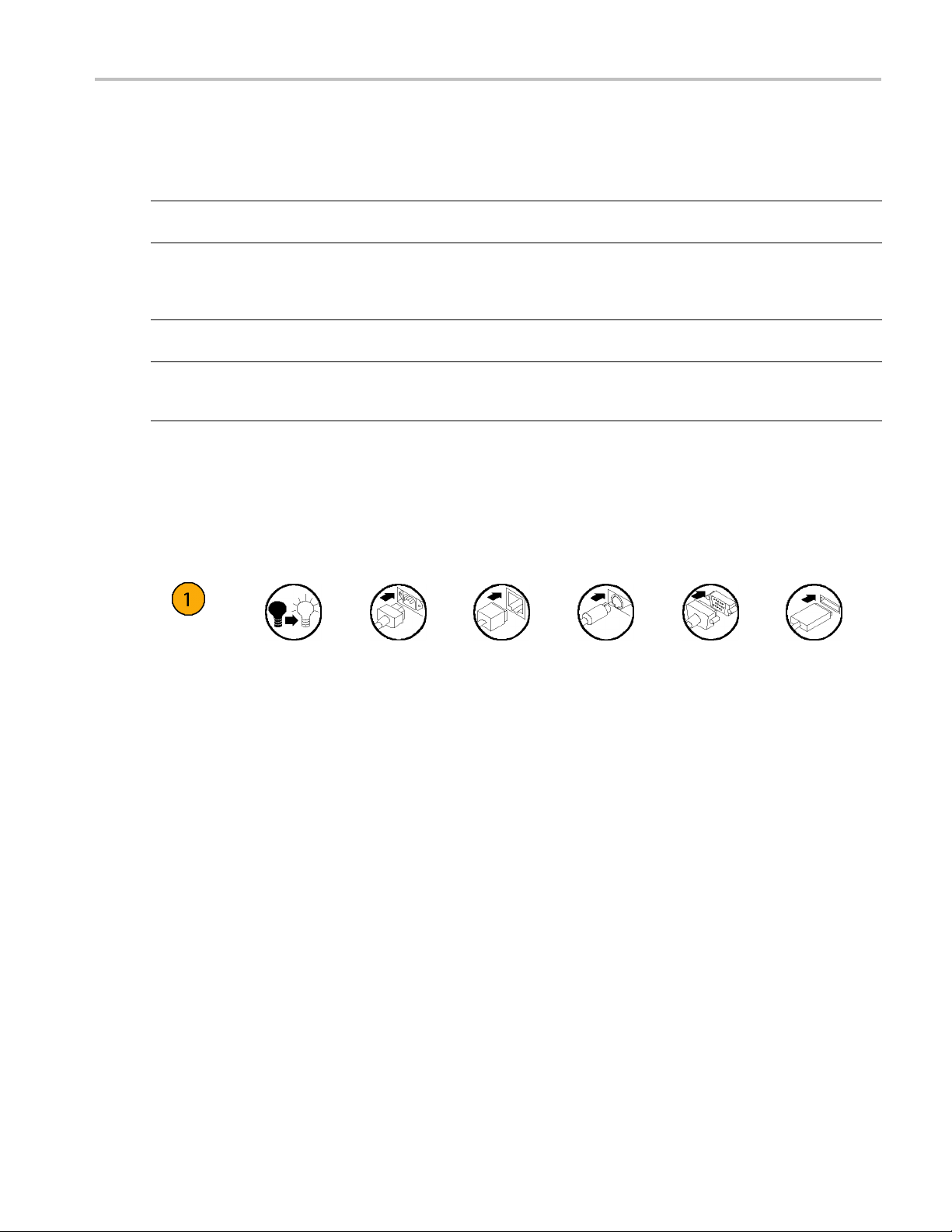
The following icons are used throughout this manual.
Preface
use your instrument.
virtually all controls and elements on screen. Online help includes detailed
instructions for using instrument functions. (See page 19, Accessing
Online Help.)
programmer guide includes the syntax of remote commands.
Read the Technical Reference for specifications and the performance
verification procedure. The Technical Reference PDF file is on the
Document CD.
Sequence
Step
Front panel
power
Connect
power
Network
PS2 SVGA USB
AWG5000B and AWG7000B Series Quick Start User Manual vii
Page 12

Preface
viii AWG5000B and AWG7000B Series Quick Start User Manual
Page 13

Installing Your Instrument
Unpack the instrument and check that you received all items listed as Standard Accessories. Recommended accessories
and instrument options are listed in the online help. Check the Tektronix Web site (www.tektronix.com) for the most current
information.
Standard Accessories
Accessory Tektronix part number
AWG5000B and AWG7000B Series Quick Start User Manual
English (Option L0)
Japanese (Option L5)
Simplified Chinese (Option L7)
Traditional Chinese (Option L8)
Russian (Option L10)
Product Software CD
Document CD
User Online Help (part of the product software)
Programmer Online Help (part of the product software)
1 Windows compatible keyboard 119-7083-00
1 Windows compatible mouse 119-7054-00
2 Stylus pens
Lead Set for DC Output
Front Protect C over
Accessory Pouch 016-1441-01
50 Ω SMA Termination, Male, DC to 18 GHz, 3 each/channel
(AWG7000 series only)
Power cord – one of the following:
North A merica (Option A0)
Universal Euro (Option A1)
United Kingdom (Option A2)
Australia (Option A3)
Switzerland (Option A5)
Japan (Option A6)
China (Option A10)
India (Option A11)
No power cord or AC adapter
(Option A99)
071-2481-xx
071-2482-xx
071-2483-xx
071-2484-xx
020-2971-xx
020-2945-xx
063-4134-xx
---
---
119-6107-00
012-1697-00
200-4963-00
015-1022-01
161-0104-00
161-0104-06
161-0104-07
161-0104-14
161-0167-00
161-A005-00
161-0306-00
161-0324-00
---
Installing Your
Instrument
AWG5000B and AWG7000B Series Quick Start User Manual 1
Page 14

Installing Your
Instrument
Operating Requirements
1. Place the instrument on a cart or bench,
observing cle
arance requirements:
Top: 20 m m (0 . 8
Left and right
Bottom: 20 mm (
Rear:75mm(3i
2. Before operat
ambient temperature is between 10 °C
and 40 °C (+50 °F to +104 °F), and
warm up the in
CAUTION. To ensure proper cooling, keep sides of the instrument clear of obstructions.
in)
side: 150 mm (5.9 in)
0.8 in)
n)
ing, ensure that the
strument for 20 minutes.
Power Supply Requirements
Source Voltage and Frequency Power Consumption
100 VAC to 240 VAC, 47 Hz to 63 Hz Less than 450 W (AWG7000 series)
Less than 560 W (AWG5000 series)
Cleaning
WARNING. To avoid personal injury, power down the instrument and disconnect it from line voltage before performing
any of the following procedures.
Inspect the arbitrary waveform generator as often as operating conditions require. To clean the exterior surface, perform
the following steps:
1. Remove loose dust on the outside of the instrument with a lint-free cloth. Use care to avoid scratching the front panel
display.
2. Use a soft cloth dampened with water to clean the instrument. Use a 75% isopropyl alcohol solution as a cleaner.
CAUTION. To avoid damage to the surface of the arbitrary waveform generator, do not use any abrasive or chemical
cleaning agents.
2 AWG5000B and AWG7000B Series Q uick Start User Manual
Page 15
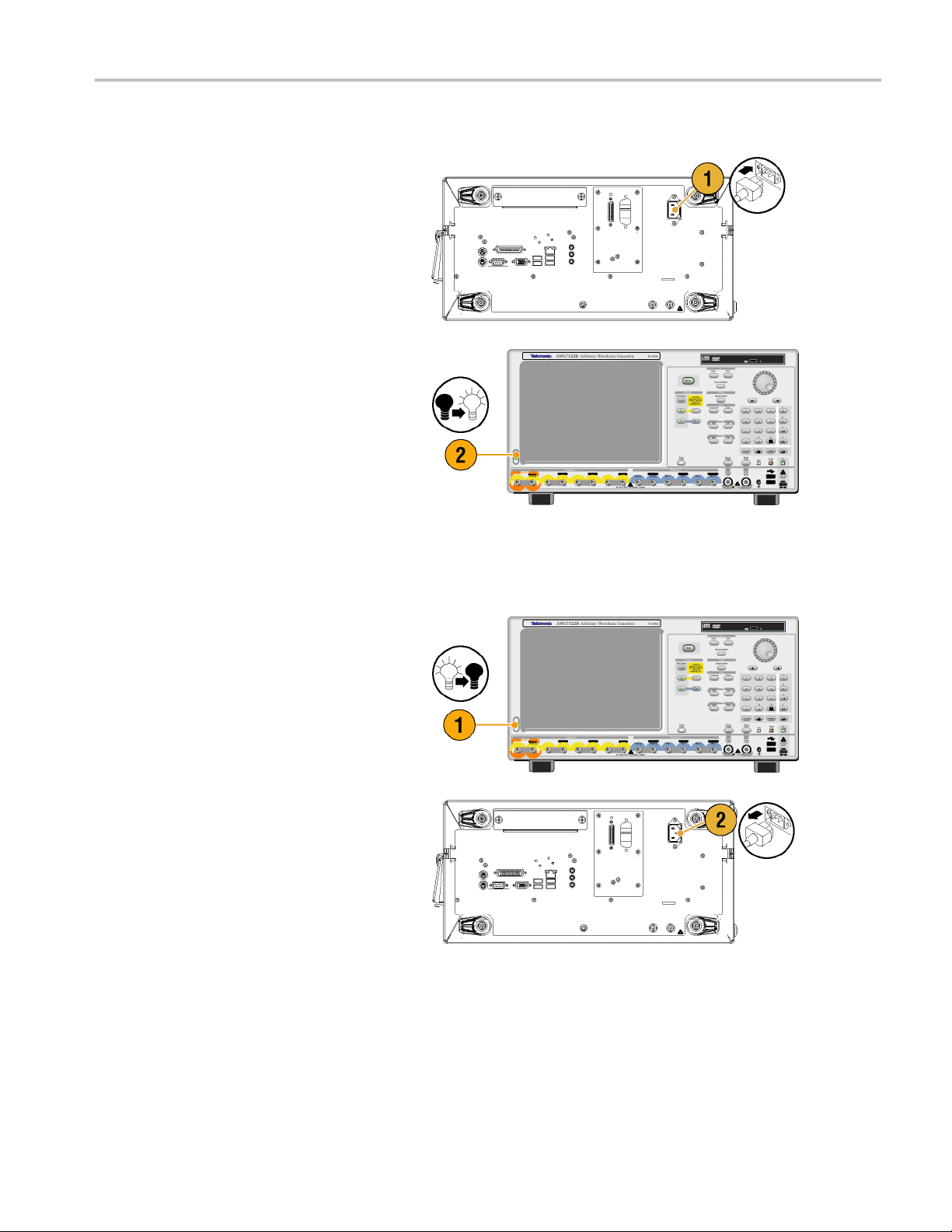
Powering On the Instrument
Installing Your
Instrument
1. Connect the AC
the instrument.
2. Use the fron
switch the instrument on.
power cord to the rear of
t-panel power button to
Powering Off the Instrument
1. Use the f
the shutdown process.
Wait approximately 30 seconds for the
instrum
2. To co m p
instrument, perform the shutdown just
described, and then remove the power
cord f
ront-panel power button to start
ent to power off.
letely remove power to the
rom the instrument.
AWG5000B and AWG7000B Series Quick Start User Manual 3
Page 16

Installing Your
Instrument
Windows Interface Guidelines
Because the instrument uses the Microsoft Windows interface, you have open access to the Windows operating system. You
can access the Windows desktop to load and run other Windows-based applications such as Microsoft Excel, WordPad, and
Paint.
Follow these guidelines to avoid making operating system changes that might cause problems or annoyances while trying to
use the instrument:
Be careful when making changes in the Control Panel. Avoid making changes to any controls with which you are
unfamiliar.
Do not delete or change any system fonts; this can affect the quality of the display.
Do not change the system Display Properties, such as the Background, Appearance, Effects, or S ettings. Making such
changes can affect the usability of the instrument and the touch screen.
Do not change the contents of the Windows folder or the Program Files\Tektronix\AWG\ System folder.
Do not change the BIOS settings; this can affect the overall operation of the instrument.
If you think that your Windows interface might cause problems with the instrument, contact your local Tektronix support
center for assistance.
Connecting to a Network
You can connect your instrument to a network for printing, file sharing, Internet access, and other functions. Consult with
your network
GPIB or LAN configuration, use the GPIB/LAN Configuration dialog box from System menu.
administrator and use the standard Windows utilities to configure the instrument for your network. For setting
4 AWG5000B and AWG7000B Series Q uick Start User Manual
Page 17
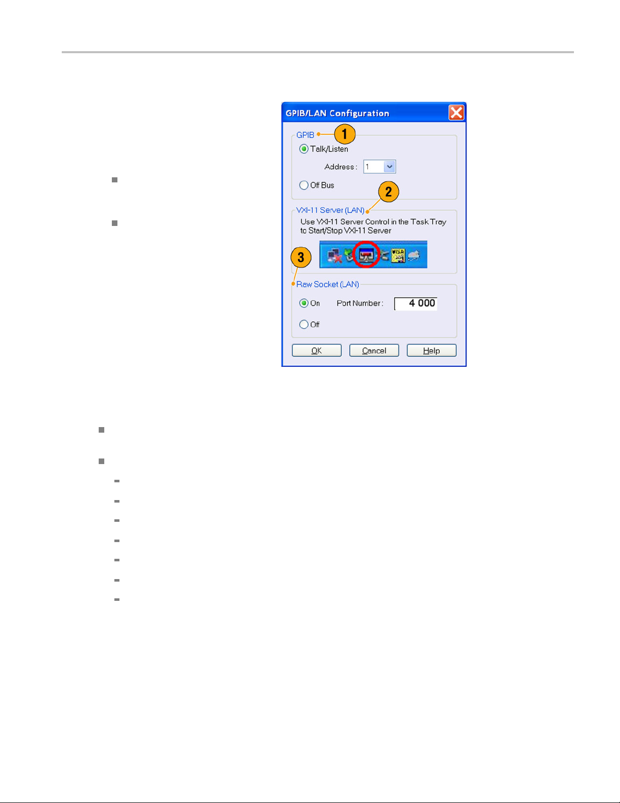
Setting GPIB/LAN
Installing Your
Instrument
Select System
to open the GPIB/LAN Configuration dialog
box.
1. Set the instrument GPIB bus
communicati
2. The instrument supports the VXI-11
Server (LAN). Use VXI-11 Server Control
in the Task T
Server.
3. TCP/IP protocol is also supported. On
and Off of socket communication are
controlled
to 4000.
> GPIB/LAN Configuration
on:
Talk/Listen
remotely control the instrument from
an external host computer.
Off Bus – Select this mode to
disconnect t
GPIB bus.
– Select this mode to
he instrument from the
ray to Start/Stop VXI-11
here. The port number is fixed
Quick Tip
If you want to start the VXI-11 Server automatically at power-on, check the "Start server automatically at system power
up" check box in the VXI-11 Server Control.
The following operations cannot be performed through a GPIB or LAN connection:
Editing a waveform
Changing size or name of waveform
Converting the w aveform format
Importing waveform data from the AWG5000 series and AWG7000 series setup (*.AWG) file
Importing a Tektronix DTG5000 series file (*.DTG)
Importing a Tektronix AWG400/500/600/700 series SEQ file
Exporting waveform data
AWG5000B and AWG7000B Series Quick Start User Manual 5
Page 18
Installing Your
Instrument
Controlling the Instrument Using a Remote PC
You can use your PC to control the arbitrary waveform generator through a LAN using the Windows Remote Desktop
function. If your PC has a larger screen, you can edit waveforms easily using your keyboard and mouse. You can also use a
third party software installed on your PC to create a waveform and import it through a network.
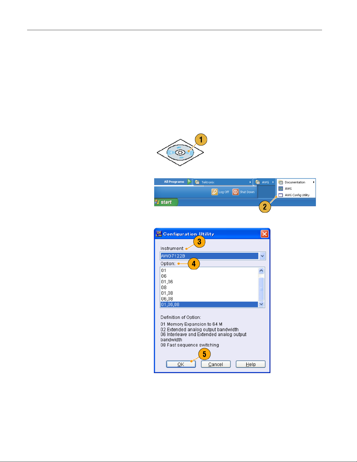
Offline Mode
The Offline Mode is a function that you can use to run the instrument application on your PC. Install the application on your
PC; the instrument hardware is not required. You can create and edit the instrument setups. The setup files that you create
can be used la
1. Use the Product Software CD provided
with the instrument to install the AWG
applicatio
2. Before using the offline mode, you must
set up the instrument confi guration.
From the Win
Programs > Tektronix > AWG > Config
Utility.TheConfiguration Utility dialog
box appear
ter with your arbitrary waveform generator.
n to your PC.
dows Start menu, select All
s.
3. Select you
4. Select you
configuration.
5. Click OK.
Run the instrument application from the
Start men
have made using the Configuration Utility
will be reflected in the application.
r instrument type.
r instrument option
u. The setup configuration you
6 AWG5000B and AWG7000B Series Q uick Start User Manual
Page 19
Inspecting Your Instrument
Two types of diagnostics are provided to verify the functionality of your instrument:
Power-on self test – Every time you power on the instrument, the instrument automatically performs the internal
diagnostics.
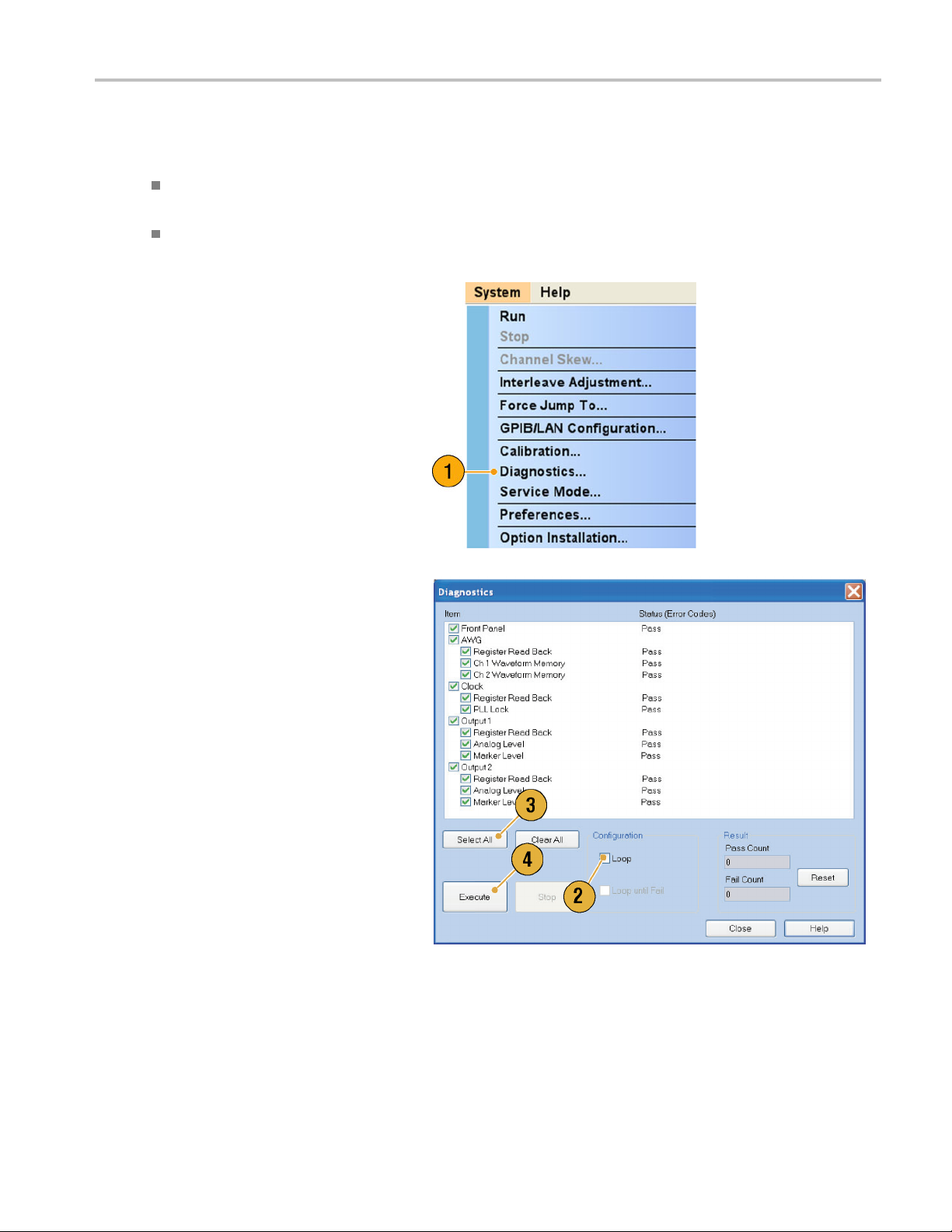
Diagnostics from the System menu – You can also run the internal diagnostics using the System menu. Use the
following procedures:
1. Select System > Diagnostics... from
the menu bar.
The Diagnostics dialog box appears.
Installing Your
Instrument
2. Confirm that the Loop box is not
checked.
If Loop is checked, the diagnostics runs
until it is manually stopped.
3. If you click Select All, all diagnostic
items are checked.
You can execute all items together or you
can execute only the selected item(s).
4. Click Execute to start the diagnostics.
Verify that the instrument passes all
tests. If diagnostic failures occur, contact
your local Tektronix service personnel.
AWG5000B and AWG7000B Series Quick Start User Manual 7
Page 20
Installing Your
Instrument
Self Calibration
The self calibration uses internal calibration routines that check electrical characteristics such as analog level and marker
level, and then adjust the internal calibration constants as necessary. Marker level is checked only in the AWG7000 series
instruments.
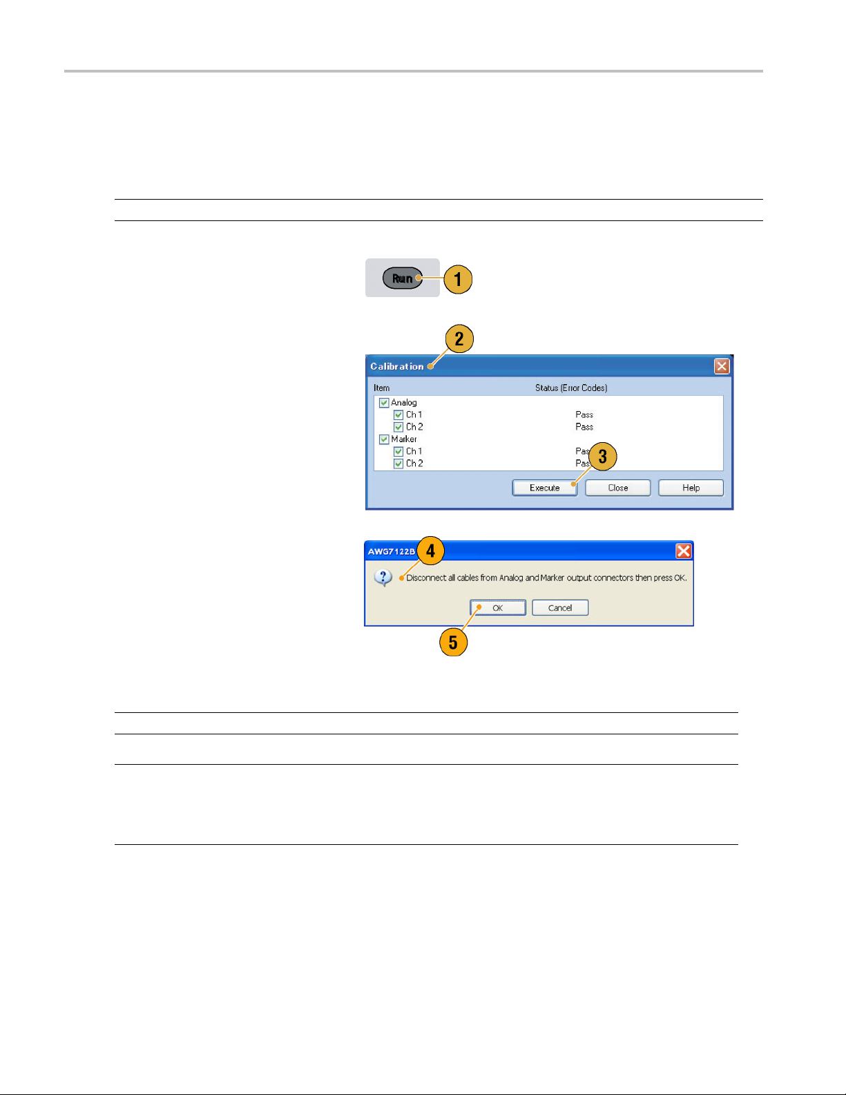
NOTE. Power on the instrument and allow a 20 minute warm-up period before performing this procedure.
1. Confirm that there is no output signal by
verifying that the front-panel Run button
indicator is off.
2. To perform the calibration suite, select
System > Calibration... from the menu
bar.
The Calibration dialog box appears.
3. Select Execute.
4. A pop-up m
all the cables from output connectors.
5. Remove the cables and then select OK.
Wait until the calibration completes.
For all ca
control should indicate Pass. If it does
not, contact your local Tektronix service
personn
NOTE. Self calibration is not valid until the instrument reaches a valid temperature. (See page 2, Operating Requirements.)
NOTE. If your instrument is an AWG7000 series, perform self calibration once a month to maintain the analog and marker
level accuracy. Failure to d o so can prevent the instrument from meeting warranted performance levels for analog
output
and marker output.
If your instrument is an AWG5000 series, perform self calibration once a year to maintain the analog output level accuracy.
essage asks you to remove
libration items, the Status
el.
8 AWG5000B and AWG7000B Series Q uick Start User Manual
Page 21
Preventing Instrument Damage
Overheat Protection
The internal instrument temperature is monitored and the instrument is protected against overheating damage by the
following actions:
A warning message will appear if the internal temperature reaches the first threshold level.
The instrument will shut down if its temperature reaches the second threshold level.
If the warning message appears or the instrument shuts down, check for the following conditions. (See page 2, Operating
Requirements
.)
Installing Your
Instrument
The ambient te
The required c
The instrumen
mperature requirement is not being met.
ooling clearance is not being met.
t fan is not working p roperly.
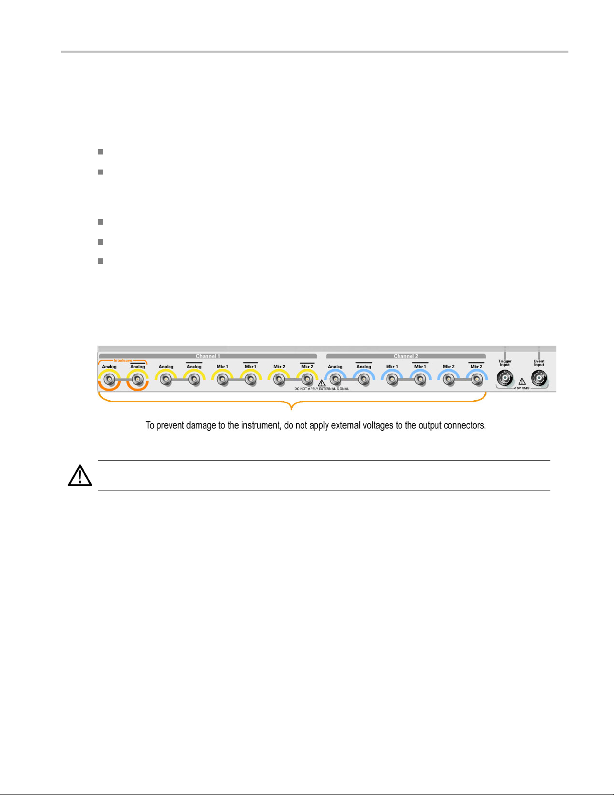
Output Connectors
The arbitrary waveform generator has both output and input connectors on the front panel. Do not apply external voltage
to the output connectors.
CAUTION. Always turn off the signal outputs when you connect or disconnect cables to/from the signal outputs connectors.
If you connect a DUT while the instrument signal outputs are in the On state, it may cause damage to the instrument or DUT.
AWG5000B and AWG7000B Series Quick Start User Manual 9
Page 22
Installing Your
Instrument
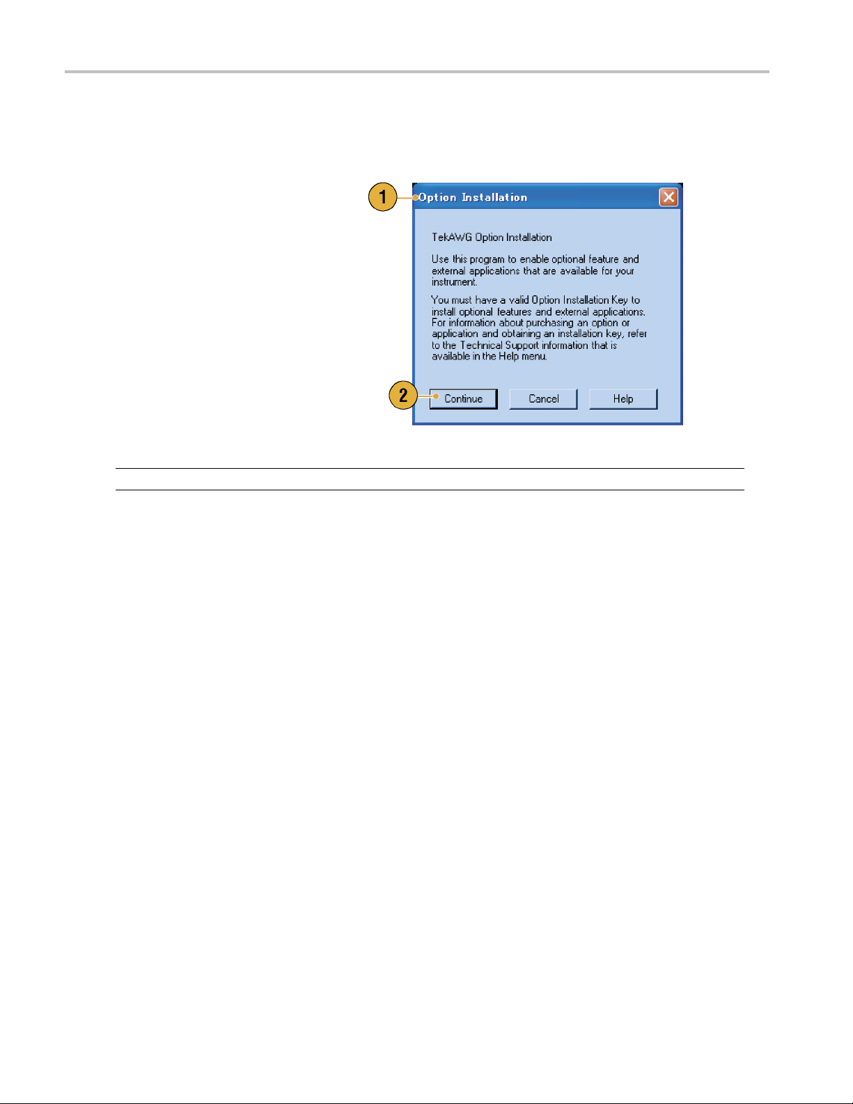
Option Installation
Use the Option Installation dialog box to enable the upgrades that you purchased from Tektronix for your instrument. For the
most current l ist of upgrades, go to www.tektronix.com or contact your local Tektronix representative.
1. Select System > Option Installation...
to open the Option Installation dialog
box.
2. Click Continu e to open the s econd
dialog box.
Enter the Option Installation Key
provided by Tektronix, and follow the
on-screen instructions to install the
option.
NOTE. After entering the option key, you must restart the instrument application to activate the option.
10 AWG5000B and AWG7000B Series Quick Start User Manual
Page 23

Creating Operat
ing System Restore CD-ROMs
Creating Oper
The instrument does not ship with operating system restore DVD. Use the following procedure to create a set of CD-ROMs
that enable you to restore the operating system if the need arises.
NOTE. This procedure creates a set of restore CD-ROMs for the Microsoft W indows operating system. After restoring
the operating system, use the Product Software CD to reinstall the instrument application software. Follow the instructions
supplied with the Product Software CD to reinstall the instrument application software.
ating System Restore CD-ROMs
Creating Restore CD-ROMs
es.
Prerequisit
A separate PC
USB flash driv
CD burner.
Blank CD-R discs (about 5; the exact number depends on the number of backup files).
To create a set of restore CD-ROMs:
1. On the instrument, navigate to C:\Tektronix\BackupImages\.
2. Using the USB flash drive (or through your LAN), transfer each of the files labeled AwgBackupN to the PC with the
CD burner.
You will need:
with a CD-R/W or DVD±R/Wdrive and CD burning software.
e (1 GB or larger) or a local area network to transfer ISO image files from the instrument to the PC with
3. Using the CD burning software, burn each of the backup ISO image files (AwgBackup1.iso to AwgBackupN.iso) to a CD.
Label each o
4. After you ha
separate hard disk, or on optical media for backup purposes. (If you ever restore the instrument OS, the ISO images
on the instrument hard disk will be erased.)
5. Store the backup CDs as defined by your company policy.
NOTE. Yo u ca
f the CDs with the backup file name, instrument name, instrument serial number, and date.
ve burned the OS restore CDs, also place copies of the disk image files (*.iso) in a network location, on a
n use restore discs only on the instrument with which they were created.
AWG5000B and AWG7000B Series Quick Start User Manual 11
Page 24

Creating Operat
ing System Restore CD-ROMs
Restoring the Instrument Operating System
You can restore the instrument operating system from either a file on the instrument hard disk drive, or from the set of
instrument restore CD-ROMs (see Creating Restore CD-ROMs). The preferred restore method is to use the hard disk
restore file.
CAUTION. Using the restore process reformats the hard drive and reinstalls the operating system. All saved data w ill be
lost. If possible, save important files to external media before performing a system restore.
Restoring the Operating System from the Instrume nt Hard Disk
The instrument contains an operating system restore file on a separate partition of the hard drive.
1. Restart the instrument. During the boot-up process you will see the following message at the top of the screen:
Starting Acronis Loader… press F5 for Acronis Startup Recovery Manager
2. Repeatedly press the F5 key until the Acronis True Image Tool opens. There is a three-second time period from when
the message appears until the instrument proceeds with the normal instrument startup. If the instrument does not open
the Acronis applica
3. Click Restore.
tion, power off the instrument, then power on the instrument and try again.
4. In the Confirmation d
The restore process takes approximately 30 minutes; the actual time depends on the instrument configuration.
ialog box, click Yes to restore the instrument operating system, or No to exit the restore process.
Restoring the Op erating System from the Restore CD-ROMs
NOTE. This procedu
NOTE. You can use restore discs only on the instrument with which they were created.
1. Insert restore CD disc 1 in the instrument CD/DVD drive.
2. Restart the instrument. The restore software opens automatically if the CD/DVD drive is the first bootable device. If
the CD/DVD drive i
restore from the CD-ROMs.
3. Click Restore.
4. In the Confirmation dialog box, click Yes to restore the operating system, or No to exit the restore process.
5. When prompted, remove the current restore CD and insert the next restore CD. Continue until the restore process
is complete.
6. When the restore process is completed, remove the last restore CD and restart the instrument. The instrument will open
into the operati
re requires that the CD/DVD drive is set as the first boot device (this is the default setting).
s not the first bootable device you must enable it as the first bootable device before performing a
ng system, settings, and appearance as shipped from the factory.
12 AWG5000B and AWG7000B Series Quick Start User Manual
Page 25
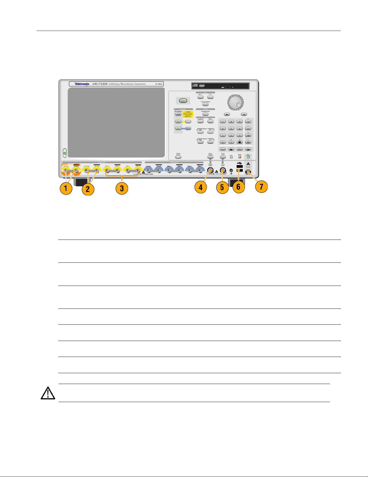
Front Panel
The following figure shows the front panel of the AWG7122B Option 06:
Front Panel
Front Panel Connectors
Connector Description
1. Interleave Output (AWG7122B Option 06 only) The interleave connectors supply analog
signals with 12 GS/s through 24 GS/s range.
Connector type: SMA
2. Analog Output
3. Marker Output
4. Trigger Input External trigger signal is applied to this connector.
5. Event Input Event signal is applied to this connector.
6. USB Two USB connectors are present on the front panel.
7. DC Output This connector supplies four channel DC voltage.
CAUTION. Always turn off the signal outputs when you connect or disconnect cables to/from the signal outputs connectors.
If you connect a DUT while the instrument signal outputs are in the On state, it might cause damage to the instrument or DUT.
These connectors supply analog signals.
Connector type: SMA (AWG7000 series)
Connector type: BNC (AWG5000 series)
These connectors supply marker signals.
Connector type: SMA (AWG7000 series)
Connector type: BNC (AWG5000 series)
Connector type: BNC
Connector type: BNC
Connect a USB device.
Connector type: 2.54 mm 2 x 4 pin header (female)
AWG5000B and AWG7000B Series Quick Start User Manual 13
Page 26

Rear Panel (AWG7
000 Series)
Rear Panel (AW
Connector Description
1. 10 MHz Reference Output Output connector for 10 MHz reference clock signal
2. Reference Clock Input Input connector for external reference clock
3. External Clock Input Input connector for oscillator input
4. GPIB Use the GPIB connector to connect the instrument to a GPIB controller
5. LAN Use the RJ-45 connector to connect the instrument to a network.
6. Parallel Port
7. USB Use the USB connectors to connect a USB mouse, keyboard, or other
8. Video
9. COM1 Use the COM1 serial port to c onnect to other devices through the serial
10. PS-2 connector Use the PS-2 connectors to connect a PS-2 keyboard or mouse to the
11. Removable HDD
12. This connector is not supported.
G7000 Series)
Connector Type: BNC
Connector Type: BNC
Connector Type: SMA
for GPIB operation.
Use the parallel port (Centronics) to connect a printer or other device.
USB device to the instrument.
Use the Video port to connect a monitor for extended desktop operation.
port.
instrument.
Removable hard disk drive to secure data. If you remove the HDD, user
information such as setup files or waveform data does not remain within
the instrument.
14 AWG5000B and AWG7000B Series Quick Start User Manual
Page 27
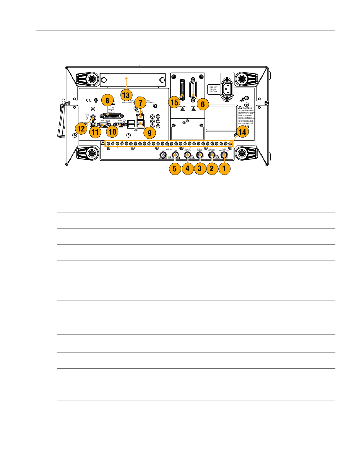
Rear Panel (AWG5
000 Series)
Rear Panel (AW
Connector Description
1. 10 MHz Reference Output Output connector for 10 MHz reference clock signal
2. Reference
3. Oscillator Output Output connector for internal oscillator
4. External Clock Input Input connector for oscillator input
5. Add Input
6. GPIB Use the GPIB connector to connect the instrument to a GPIB controller for GPIB
7. LAN Use the RJ-45 connector to connect the instrument to a network.
8. Parallel
9. USB Use the USB connectors to connect a USB mouse, keyboard, or other USB device
10. Video
11. COM1 Use the COM1 serial port to connect to other devices through the serial port.
12. PS-2 connector Use the PS-2 connectors to connect a PS-2 keyboard or mouse to the instrument.
13. Removable HDD
14. Digital
15. This con
Clock Input
Port
Data Out
nector is not supported.
G5000 Series)
Connector
Input conn
Connector Type: BNC
Connector Type: BNC
Connector
Add extern
Connector Type: BNC
operation.
Use the parallel port (Centronics) to connect a printer or other device.
to the instrument.
Use the Video port to connect a monitor for extended desktop operation.
Removable hard disk drive to secure data. If you remove the HDD, user information
such as s
Use these connectors to output digital data. To enable digital data output, option
03 must b
Connector Type: SMB
Type: BNC
ector for external reference clock
Type: BNC
al signal to the output signal of arbitrary waveform generator
etup files or waveform data does not remain within the instrument.
e installed in the AWG5002B or AWG5012B.
AWG5000B and AWG7000B Series Quick Start User Manual 15
Page 28

Getting Acquain
ted with Your Instrument
Getting Acqua
Control Panel
inted with Your Instrument
Buttons/Keys Description
1. Run
2. All Outputs On/Off If one or more Outputs are on, they will all be turned off when you push the
3. Channel Output On These buttons are used to enable/disable the channel output. If the output
4. Channel Select These buttons are used to select a channel that you w ant to interact with. If
5. File – O pen/Save When the Open or Save button is pushed, the corresponding dialog box is
6. Factory Default When this button is pushed, the specified default setups are recalled. (See
7. Sampling Rate When you push this button, the sampling rate parameter in the Settings
The Run button is used to start and stop the signal generation. If the signal
is being generated, the LED indicator lights up.
To output the signal through the output connectors, you must push the
front-panel All Outputs On/O ff button or the Channel Output On button.
All Outputs On/Off button. If all Outputs are off, they will all be turned on
when you push the All Outputs On/Off button.
is in the On state, the LED is turned on.
a channel select button on the front panel is pushed, the selected channel
page in the Settings Window will be activated.
displayed. You can load or save a setup (*.AWG) file using this dialog box.
page 42, Default Setup.)
window is selected. Sampling Rate is common to each channel.
16 AWG5000B and AWG7000B Series Quick Start User Manual
Page 29

Getting Acquain
Buttons/Keys Description
8. Level – Amplitu
9. Marker 1 and Marker 2 – High/Low When you push one of these buttons, the Marker High or Marker Low
10. Touch Screen Off When the Touch Screen is On state, you can use your finger or stylus to
11. Force Trigger When you push this button, the instrument generates an internal trigger
12. Force Event When you push this button, the instrument generates an internal event
13. General Purp
14. Digit Selec
15. Numeric Keypad
de/Offset
ose Knob
t Arrow Keys
When you push th
corresponding channel in the Settings window is selected.
Amplitude and offset can be set independently for each channel.
parameter of t
Marker High and Marker Low can be set independently for each channel.
control the screen interface. The LED is lit while the Touch Screen interface
is disabled.
signal.
signal.
The knob is us
a pop-up menu, pull-down menu, or dialog box. Turn the knob clockwise
to increase the value, and turn the knob counterclockwise to decrease
the value.
The digit se
field that contains an editable number. After you specify the digit, you can
change the number with the knob.
Units prefix buttons (T/p, G/n, M/μ, and k/m) are used to complete an input
with the nu
these prefix buttons without pressing the Enter key.
If you push the units prefix buttons for frequency, the units are interpreted
as T (teratime, the units are interpreted as p (pico-), n (nano-), μ (micro-), or m (milli-).
ese buttons, the amplitude or offset parameter of the
he corresponding channel in the Settings window is selected.
ed to increase or decrease a set value or select an item from
lect arrow keys are used to move the under bar (cursor) to a
meric keypad. You can determine the units by pushing one of
), G (giga-), M (mega-), or k (kiro-). If you push the buttons for
tedwithYourInstrument
CAUTION.
signal outputs are on.
Do not power on or off the DUT when the arbitrary waveform generator signal outputs are on.
Do not connect a DUT (Device Under Test) to the front-panel signal output connectors when the instrument
Locking and Unlocking the Front Panel Controls
The front panel may be locked by a remote user while the arbitrary waveform generator is being remotely controlled via GPIB
or Ethernet. When the front panel is locked, all keys and buttons are disabled except the power switch. You cannot use your
mouse or keyboard. However, the Windows operations are available even if the instrument front panel is locked.
To unlock the front-panel controls, use a remote command or push the front-panel Cancel button twice. If you exit the
application, the lock state is cleared. When you restart the application, the front-panel controls are unlocked.
AWG5000B and AWG7000B Series Quick Start User Manual 17
Page 30

Getting Acquain
ted with Your Instrument
Touch Screen Interface
The arbitrary waveform generator offers two methods of making menu selections:
Front-panel controls, keyboard, and mouse (keyboard and mouse are standard accessories)
Front-panel controls and touch screen interface
1. You can enable or disable the touch
screen interface by pushing the
front-panel Touch Screen button.
When the touch screen is in the Off state,
the LED is lighted. You can still access
the on-screen menus with a mouse or
keyboard.
Quick Tip
You need to adjust the touch screen when one of the following occurs:
The operating system is restored
The hard d isk drive is exchanged
The touch screen is not responding correctly
Run the touch screen program from the shortcut on the Windows desktop to adjust the touch screen.
18 AWG5000B and AWG7000B Series Quick Start User Manual
Page 31
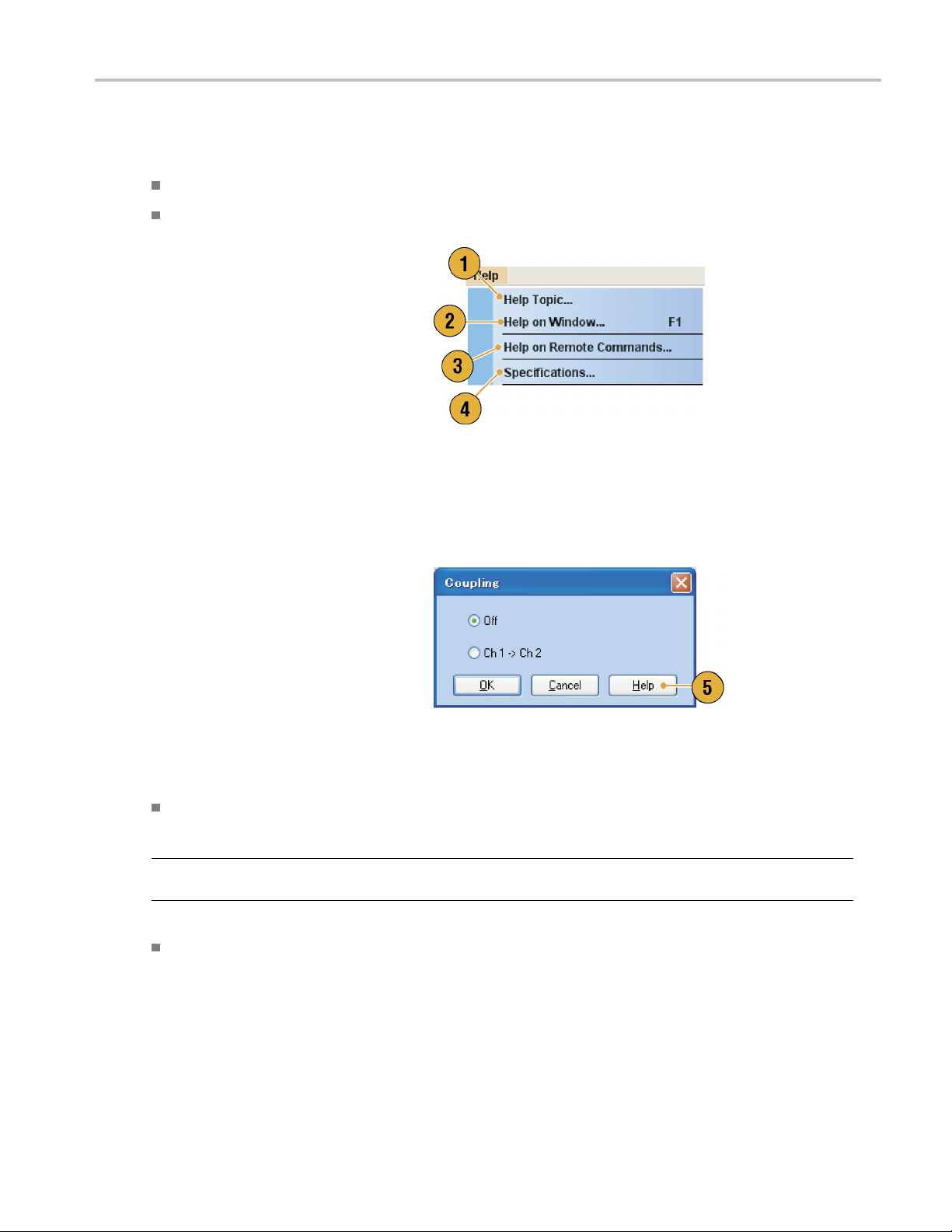
Accessing Online Help
The arbitrary waveform generator provides two types of online help:
User online help – In-depth information is available in the online help on all the features of your instrument.
Programmer online help – The instrument offers programmer online help about remote commands.
To access the Help system, select Help from
the menu bar.
1. To access the user online help, select
Help > Help Topic....
2. To use context-sensitive help on the
current setup, select Help > Help on
Window... or press F1.
3. To access Programmer Online Help,
select Help > Help on Remote
Commands....
4. To acces s specifications and
performance verification, select
Specifications to open the PDF
Technical Reference Manual.
Getting Acquain
tedwithYourInstrument
5. Most dialog boxes have a Help button.
For contextual overviews of the dialog
box, click the button to open the help
system with an overview of the dialog
box that is displayed.
Quick Tips
You can s
use the System menu > Preferences dialog box. (Se e page 27, Setting the User Preferences.)
NOTE. When you fi rst open the Japanese user online help, a pop-up message is displayed to prompt you to install the
Japanes
The programmer online help is available only in English.
elect English or Japanese for the user online help. By default, English is selected. To change the language,
e language pack. Click Install to install the language pack.
AWG5000B and AWG7000B Series Quick Start User Manual 19
Page 32

Getting Acquain
ted with Your Instrument
Screen Interface
Screen element Description
1. Menu bar
2. Status bar The status bar shows information about the instrument, such as sampling
3. Waveform List window User-defined waveforms and predefined waveforms are listed in this
4. Sequence window This window mainly provides information on output sequence.
5. Waveform window This window displays the waveform that you selected in the Settings
6. Settings window This window is provided for quick access to the parameter settings.
7. Window tag
8. Remote command bar Displays a remote command corresponding to current instrument operation.
The menu bar provides access to all of the instrument functions.
rate, run mode status, or output status
window.
window or in the Sequence window.
Click these tags to toggle display of corresponding windows on or off.
20 AWG5000B and AWG7000B Series Quick Start User Manual
Page 33

Basic Steps for Using the Arbitrary Waveform Generator
After y ou have powered on the instrument, use the application’s menu bar or control windows to create and edit a waveform.
(See page 23, Accessing Menus and Control Windows.) Do the following steps to output a waveform or a sequence:
1. To create a new waveform, select Edit
> Standard Waveform.... The created
waveform is displayed in the Waveform
List window.
2. To use an existing waveform, select File
> Open File... to open a setup file, and
then select a waveform in the Waveform
List window.
3. Confirm the Run mode. Check that the
desired run m ode is selected on the Run
Mode tab of the Settings window.
Getting Acquain
tedwithYourInstrument
4. Togenerate a signal, push the front-panel
Run button or the Run button on the
Status Bar.
5. Use one of the following methods to set
the channel output On:
Front-panel Channel Output On
button or All Outputs On/Off button
Output On button of the Ch page of
Settings window
AWG5000B and AWG7000B Series Quick Start User Manual 21
Page 34

Getting Acquain
Run Mode
The arbitrary waveform generator supports the following four types of Run mode:
Continuous. A continuous waveform is output.
Triggered. A waveform is output once when the instrument receives a trigger signal. The instrument will wait for the next
trigger signal after outputting the waveform.
Gated. A waveform is output only when a gate signal is asserted. A c ontinuous waveform is output while the gate
signal stays asserted.
Sequence. Multiple waveforms can be output in the order specified in the sequence.
You can select a run mode using the Run Mode page of Settings window.
1. Select a Run mode.
2. In the Triggered or Gated mode, you
can select the output value while the
instrument is in the waiting-for-trigger
state.
ted with Your Instrument
First – Sets the output level to the
first value of the waveform
Last – Sets the output level to the
last value of the waveform
Trigger Control
Trigger controls waveform output when the Run mode is Triggered, Gated or Sequence. Use the Trigger page of Settings
window to set Trigger parameters.
1. You can select Trigger Source (Inter
or External). The default is External.
2. If External is selected, Trigger Level,
Trigger Slope, and Trigger Impedance
canbeset.
Level – S ets external trigger level
Slope – Determines whether the
instrument finds trigger point on the
rising edge or the falling edge of the
signal.
nal
.
Impedance – Specifies external
trigger impedance (1 kΩ or 50 Ω).
3. If Internal is selected, internal trigger
Interval can be set.
22 AWG5000B and AWG7000B Series Quick Start User Manual
Page 35

Quick Tips
Trigger parameters control the signal outputs of the instrument. Trigger parameters cannot be set if Continuous is
selected in the Run Mode.
You can also control the trigger by pushing the front-panel Force Trigger button in addition to specifying a signal as
the trigger source.
Accessing Menus and Control Windows
You can access menu commands and control windows using the following techniques:
1. Click Settings from the menu bar, and
then select a
The selected item in the Settings window
will become active.
command.
Getting Acquain
tedwithYourInstrument
2. For a shortcut to settings menus, you
can use the Settings window.
Clicking a tab, such as Ch 1 or Timing,
on the Settings window opens the
corresponding page that you can use to
select the instrument settings.
3. From the front panel, you can quickly
access the parameters for sampling rate,
amplitude level, offset level, and marker
level.
If you push one of these buttons, the
corresponding parameter in the Settings
window will be selected.
AWG5000B and AWG7000B Series Quick Start User Manual 23
Page 36

Getting Acquain
ted with Your Instrument
4. You can right-c
to associated menu commands.
For example, right-click on the Waveform
List window to d
commands.
lick to gain quick access
isplay the related menu
Changing Control Settings
As you configure the instrument, you might need to set a numerical parameter such as an amplitude level or offset. To set
these parameters in a screen window, touch or click the parameter to select it. Once the parameter is selected, the general
purpose kn
You can use
ob is assigned to the parameter.
the general purpose knob to change parameters, although the following methods are generally available.
1. Some parameters have increase/
decrease buttons. These buttons are
ed spin buttons. Touch or click
also call
the spin buttons to change to the next
available value.
To m ove th
contains an editable number, use the digit
select arrow keys. (See page 16, Getting
Acquain
2. Some par
keypad or keyboard that you can use to
enter a new value.
Touch o
icon to display the keypad (or keyboard).
e underbar to a field that
ted with Your Instrument.)
ameters supply a pop-up
r click the keypad (or keyboard)
24 AWG5000B and AWG7000B Series Quick Start User Manual
Page 37

Display/Hide Control Windows
The arbitrary waveform generator displays four control windows by default. You can quickly hide or display each window
using the window tag.
1. By default, four windows are displayed if
the Run mode is Sequence.
2. Click the Settings tag.
Getting Acquain
tedwithYourInstrument
3. The Settings window is hidden.
AWG5000B and AWG7000B Series Quick Start User Manual 25
Page 38

Getting Acquain
Status Bar
The Status Bar has two functions. It displays the status of the instrument, such as Sampling Rate, Run State, and Run Mode.
It also has action buttons, such as Force Trigger, Force Event, All Outputs On/Off, and Run.
1. Sampling Rate Sampling rate setting is displayed.
2. Run Status Instrument status (Running or Stopped) is displayed.
3. Run Mode Run Mode is displayed.
4. Force Trigge
5. Force Event
6. All Outputs On/Off button Same function as the front-panel All Outputs On/Off button.
7. Run button
ted with Your Instrument
r button
button
Same function as the front-panel Force Trigger button.
Same function as the front-panel Force Event button.
Same function as the front-panel Run button.
26 AWG5000B and AWG7000B Series Quick Start User Manual
Page 39
Setting the User Preferences
Getting Acquain
tedwithYourInstrument
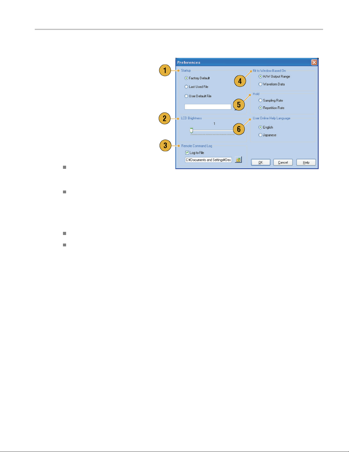
Select System
Preferences dialog box.
1. Startup – Select a power-on setting.
(See page 42, Changing Settings at
Power-on.)
2. LCD Brightne
brightness.
3. Remote Command Log – You can r ecord
the sequence of GPIB commands you
used with you
4. Fit to Window
vertical scale setting when you use the
Zoom Fit function.
5. Hold – Select which parameter is held
when the eff
modified.
> Preferences... to open the
ss – Set the LCD
r instrument.
Based On – Select the
H/W Output Range – Vertical scale
is set based
hardware limitation.
Waveform Data – Vertical scale is
set based on the waveform data.
on the instrument
ective waveform length is
Sampling Rate
Repetition Rate
6. User Online Help Language – Select a
language in which to display on the User
Online Hel
p.
AWG5000B and AWG7000B Series Quick Start User Manual 27
Page 40

Getting Acquain
ted with Your Instrument
Changing the Windows Display Style
You can c o n figure the appearance of Waveform and Sequence windows for your arbitrary waveform generator.
Waveform Window
1. Select View > Display Properties... to
display the Display Properties dialog box.
Click the Waveform Window tab.
2. You can select the Waveform window
display format (Graphic or Table).
3. This example shows Graphic display.
The view is fixed to Analog. You can
select on and off for Overlay and Grid.
4. When Overlay is specified, analog data
from multiple channels can be displayed
overlaid.
5. Select waveform thickness.
6. You can select vertical units. Select
Voltage or Normalized in the View data
as box.
7. You can select horizontal units. Select
Points or Time in the Scale box.
8. Click Tab le to set the Waveform window
to Table display.
9. You need to select Analog or Digital
when Table is specified.
10. When Digital is selected, you can select
Binary or HEX.
11. You can select the vertical and horizontal
units. If Digital is selected in the Table
display, vertical units selection (Voltage
or Normalized) is disabled.
12. You can select displayed items for each
channel in the Waveform window.
28 AWG5000B and AWG7000B Series Quick Start User Manual
Page 41
Sequence Window
Getting Acquain
tedwithYourInstrument
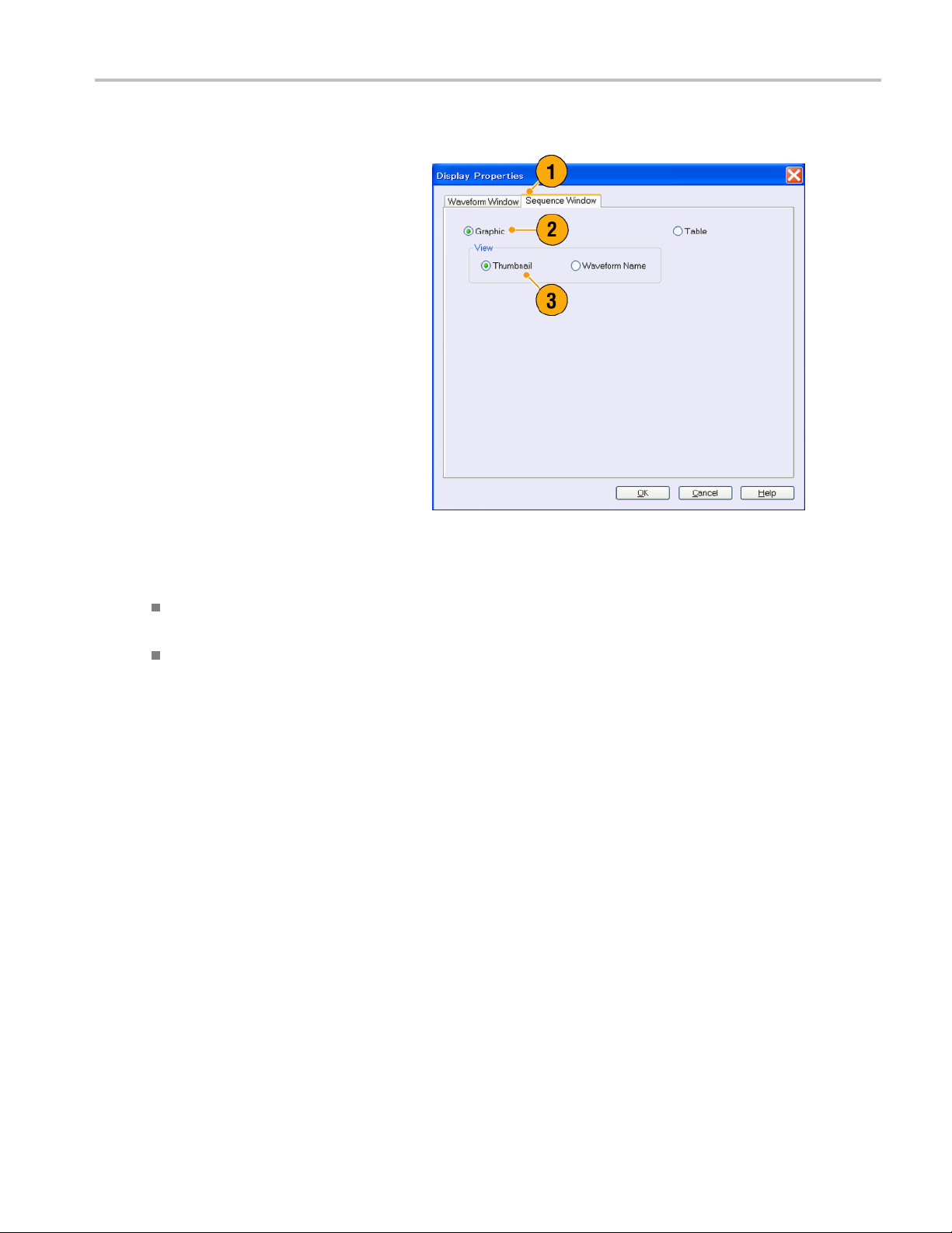
1. Select View > D
display the Display Properties dialog box.
Click the Sequence Window tab.
2. You can select the display format
(Graphic or Ta
3. When Graphic i
either Thumbnail or Waveform Name.
isplay Properties... to
ble).
s selected, you can select
Quick Tips
(AWG7000 series only) When the DAC resolution of a channel is set to 10 bits, the marker data of the channel cannot
ayed.
be displ
You can a
lso access the Display Properties dialog box by right-clicking o n the Waveform or Sequence window.
AWG5000B and AWG7000B Series Quick Start User Manual 29
Page 42

Getting Acquain
ted with Your Instrument
Run State Control and Output On/Off
Do the following steps to control the start and stop of signal generation for the arbitrary waveform generator.
1. Use the front-panel Run button to start
and stop signal generation.
Switching signal generation on or off is
called Run State control.
If a signal is being generated, the LED
indicator lights up.
2. To output the signal through the output
connectors, push the front-panel All
Outputs On/Off button or the Channel
Output On button.
3. Alternatively, you can use the Ch n
(Channel)
enable the signal output.
tab on the Settings window to
30 AWG5000B and AWG7000B Series Quick Start User Manual
Page 43
Setting Output Signals
Analog and Marker Output
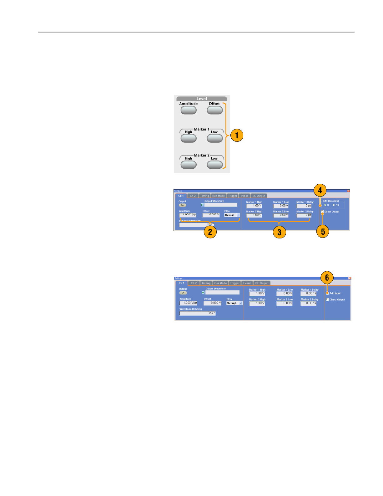
You can set the parameters for analog and marker output signals using the front panel buttons or the Channel page
of Settings wi
1. Use the front-panel Level buttons to
set the Amplitude, Offset, and Marker
High/Low for
ndow.
each channel.
Getting Acquain
tedwithYourInstrument
2. In the same w
for Amplitude, Offset, and Filter using the
Ch n page of Settings window.
3. You can set parameters for marker high,
low and del
4. (AWG7000 s
Resolution is selected, Marker Outputs
will be disabled.
5. Select Direct Output On and Off.
6. (AWG5000 series) You can add an
external
output.
ay, you can set parameters
ay.
eries) When 10 bits DAC
signal to each channel analog
AWG5000B and AWG7000B Series Quick Start User Manual 31
Page 44

Getting Acquain
ted with Your Instrument
7. When the instru
non-sequence mode, you can select the
output waveform data using the Output
Waveform field.
icon to display the Waveform List dialog
box.
8. You can set phase shift or delay for each
analog output
is in the non-sequence mode.
ment is in the
Click the waveform list
signal when the instrument
Quick Tips
Each channel has independent output on and off control. When the output status of Ch n is set to On, both analog output
and marker output are enabled.
When Direct Output is set to On, filter and offset settings become inactive. The analog bandwidth setting range will
change.
(AWG7000 series) The Option 02 (Extended analog output bandwidth) and Option 06 (Interleave and wide bandwidth
direct output) models do not have the control settings for Filter, Offset, and Direct Output.
(AWG5000 series) You can use Add Input when Direct Output is set to off. If Direct Output is selected, Add Input
is disabled.
The Waveform Rotation can be set independently for each channel.
Analog Phase – Can be set by degree (°).
Analog Delay – Can be set by time or points.
The Waveform Rotation setting does not affect the Waveform window display.
DC Output Page
1. The arbitrary waveform generator has
four lines of DC output.
The level of each output can be set
independently.
2. The output state (On or Off) of the
DC output is common to all DC output
channels.
32 AWG5000B and AWG7000B Series Quick Start User Manual
Page 45

Getting Acquain
Timing Control
You can set parameters for sampling rate or clock using the Timing page of Settings window.
1. Sets Sampling Rate.
2. You can set Repetition Rate when the
Run mode is not set to Sequence.
3. You can select Clock Source (Internal
or External).
If External is selected, the clock
signal from External Oscillator Input
is used.
If Internal is selected, the clock signal
is generated internally.
4. Divider Rate can be set when the Clock
Source is set to External.
5. You can select the Reference Source
(Internal or External).
Reference Source is selectable only
when the Clock Source is set to Internal.
tedwithYourInstrument
6. You can select the External Reference
Type (Variable or Fixed).
This parameter is selectable only w hen
the Clock Source is set to Internal and
the R eference Source is set to External.
Quick Tips
The S ampling Rate can be set when the internal clock source is selected and one of the following conditions is met:
Internal is selected as the reference source.
External is selected as the reference source and Fixed is selected as the external reference type.
The arbitrary waveform generator accepts a 10 MHz, 20 MHz, or 100 MHz frequency signal as a Fixed external
reference source.
You can set the Multiplier Rate when the Clock Source is set to Internal, the Reference Source is set to External, and
the Extern
al Reference Type is set to Variable.
AWG5000B and AWG7000B Series Quick Start User Manual 33
Page 46

Getting Acquain
Channel Coupling
You c an change the parameter values for multiple channels at a time. This function is called Channel Coupling.
1. Select Settings > Coupling... to open
the Coupling dialog box.
You can also open this dialog box
from the pop-up menu displayed by
right-clicking on the Channel page of the
Settings window.
2. Select a coupling method.
Ch1–>Ch2andCh3–>Ch4means
that Ch 1 and
are coupled, respectively.
3. Select Ch1->Ch2,Ch3,Ch4to
couple the Ch 1 parameters with Ch 2,
Ch 3, and Ch
ted with Your Instrument
Ch 2, and Ch 3 and Ch 4
4 parameters.
Quick Tips
Ch 1-> Ch
Channel Coupling in the On state, the Ch 1 parameters are applied to the instrument hardware settings of the other
three channels. You cannot select parameters for channel coupling in the Channel page of the Settings window. The
disable
The foll
2, Ch 3, Ch 4 means that Ch 1 parameters are coupled with Ch 2, Ch 3 and Ch 4 parameters. With the
d parameters are grayed out.
owing parameters are excluded from channel coupling:
Channel
Output w
Sequenc
Externa
Wavefor
Marker d
Paramet
skew
aveform
e waveform
l signal add function
m rotation
elay
ers that are not related to the output signal, such as marker display on/off
34 AWG5000B and AWG7000B Series Quick Start User Manual
Page 47

Getting Acquain
Channel Skew Adjustment
The channel skew adjusts the skew (delay) of each channel output.
Select System > Channel Skew... to open
the Channel Skew dialog box.
1. You can adjust the skew for each channel
independently. This adjustment applies
to analog output and marker output.
2. Adjusting the skew value will update the
dialog box display.
NOTE. If your instrument is a single channel model, the channel skew function is not supported.
tedwithYourInstrument
AWG5000B and AWG7000B Series Quick Start User Manual 35
Page 48
Getting Acquain
ted with Your Instrument
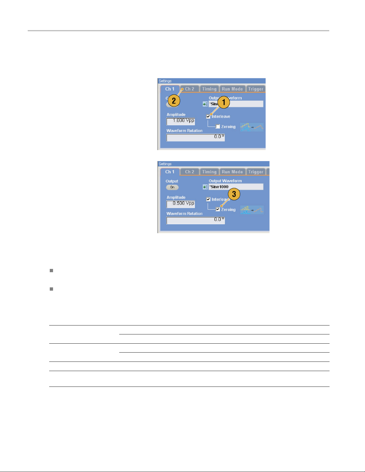
Interleave (AWG7122B Option 06)
The AWG7122B Option 06 offers interleave capability. The instrument can interleave two channels to attain higher sampling
rates and longer waveform length.
1. To activate Interleave, select the Ch 1
page of Settings window, and then check
the Interleave check box.
2. When Interleave is set to On, the Ch 2
tab is grayed out. You cannot access the
Ch 2 parameters.
3. When Interleave is in the On state, you
can select Zeroing On/Off.
The bandwid
amplitude range is changed with Zeroing
On. The default is Zeroing Off.
th becomes wider but the
Quick Tips
Interleaving is applied to analog output. When interleaving is on, marker data with even numbers will be output, such
as 0,0,2,2,4,4,6,6.
When output is on, changing the Interleave mode on and off will turn the output off.
The following table lists how interleaving extends the maximum sampling rate and waveform length:
Instrument type and
option Interleave Sampling rate Waveform length
AWG7122B Option 01,
Option 06
AWG7122B Option 06
AWG7122B Option 01
AWG7122B Standard
model
On 12 GS/s to 24 GS/s
Off 10MS/sto12GS/s
On 12 GS/s to 24 GS/s
Off 10MS/sto12GS/s
Not available
Not available
10 MS/s to 12 GS/s
10 MS/s to 12 GS/s
1 to 129,600,000 points
1 to 64,800,000 points
1 to 64,800,000 points
1 to 32,400,000 points
1 to 64,800,000 points
1 to 32,400,000 points
36 AWG5000B and AWG7000B Series Quick Start User Manual
Page 49

Getting Acquain
tedwithYourInstrument
Interleave Adjustment
Interleaving is a function to attain twice the sampling rate of single channel by combining the Ch 1 and Ch 2 outputs. When
the interleaving is set to On, you can adjust the relative values for Phase and Amplitude between the channels.
1. In this example, Ch 1 amplitude is set to
0.75 Vp-p. Use the Settings window to
enter Ch 1 amplitude value.
2. Select System > Interleave
Adjustment... to open the Interleave
Adjustment
Enter 0.100 Vp-p in this example as an
adjustment value of relative amplitude.
3. Both Ch 1 and Ch 2 amplitude values
are adjuste
Tip below for calculation formula.
dialog box.
d internally. See the Quick
4. The phase adjustment will be done by
fixing Ch 1 and changing Ch 2. The
adjustmen
setting range is as follows:
Quick
Both Ch 1 and Ch 2 will be adjusted internally in the amplitude adjustment. The internal amplitude values for each
channel will be calculated as follows:
NOTE. You can set the amplitude adjustment value within the range of Ch 1 amplitude setting. The adjustment value may
be clipped to maximum or minimum value depending on the Ch 1 amplitude setting. The clipped value will be applied to
the instrument hardware.
t units are degrees. The
-180.0 to +180.0 degrees
Tip
Internal Ch 1 Amplitude = Ch 1 Amplitude Value – Adjustment Value
Internal Ch 2 Amplitude = Ch 1 Amplitude Value + Adjustment Value
AWG5000B and AWG7000B Series Quick Start User Manual 37
Page 50
Getting Acquain
ted with Your Instrument
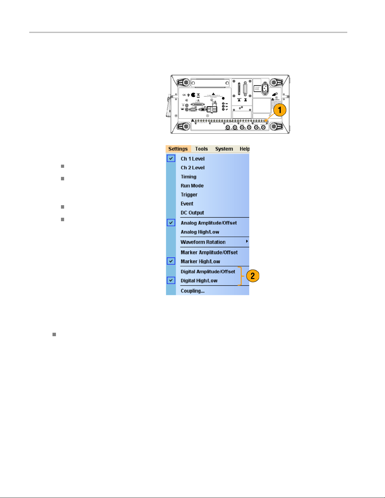
Digital Output (AWG5002B/AWG5012B Option 03)
The AWG5002B/AWG5012B Option 03 supports digital data output.
1. The SMB connectors for 14 bit digital
data output are present for Ch 1 and
Ch 2 on the rear panel.
2. You can set the output parameters as
follows:
Digital Amplitude/Offset
Digital High/Low
The digital
follows:
output levels are fixed as
–1.0 V to +2.7 V, into 50 Ω
0.01 V resolution
Quick Tip
Each channel has independent output on and off control. When the output status of Ch n is set to On, both analog
t and digital output are enabled.
outpu
38 AWG5000B and AWG7000B Series Quick Start User Manual
Page 51

Saving and Recal
ling Setups
Saving and Rec
Use the File menu for basic fi le operations such as saving or recalling instrument setups or importing or exporting waveform
data. You can also use the File menu for standard Windows operations such as loading the most recent setup files.
File Menu
The following menu items are provided in the File menu. For a complete description of each m enu command, refer to
the instrumen
1. Recalls factory default setups. (See
page 42, Default Setup.)
2. Opens a dialog box to load an instrument
setup.
3. Saves (Overw
4. Saves an inst
new setup file name.
5. Use these commands to import
waveform data.
6. Exports waveform data to a file for use
with other a
t online help system.
rites) an instrument setup.
rument setup assigning a
pplications.
alling Setups
7. Alistofset
is displayed here.
8. The application closes.
9. The application closes and then the
instrument shuts down.
up files you accessed recently
Quick Tip
You can also shut down the instrument by pushing the front-panel power button (On/Standby switch) while the application
is running. When the power button is pushed, a dialog box asks you whether to save current setups. If you select Yes,
the current setups are preserved and then the instrument will start the shutdown process.
AWG5000B and AWG7000B Series Quick Start User Manual 39
Page 52
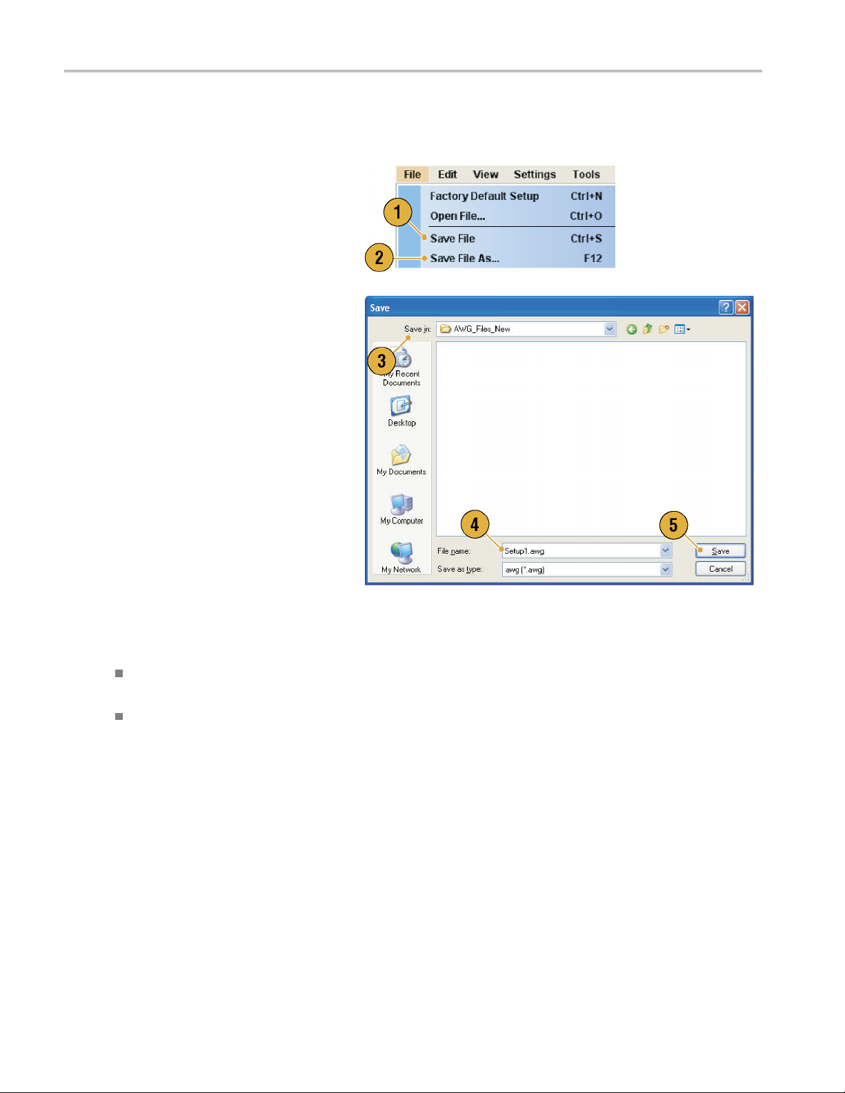
Saving and Recal
ling Setups
Saving an Instrument Setup
Use the following steps to save an instrument setup:
1. Select File > Save File to overwrite
theexistinginstrumentsetupwithan
updated setup file.
2. To save the current setup to a new setup
file, select File > Save File As... or push
the front-panel Save button.
3. Select a location w here you want to save
the setup.
4. Type a file na
5. Click Save.
me or use the default name.
Quick Tips
If a setup file contains Integer format waveform(s), the file size is reduced. For more information about waveform
data format (Real or Integer), refer to the online help.
To change the waveform format in the Waveform, Waveform List, or Settings window, you can use the Waveform
ties dialog box. (See page 55, Confirming Waveform Properties.)
Proper
40 AWG5000B and AWG7000B Series Quick Start User Manual
Page 53

Recalling an Instrument Setup
You can recall an instrument setup from the File menu or from Windows Explorer.
1. Select File > Open F ile... to open the
Open File dialog box.
2. Select a setup file.
3. Click Open.
Saving and Recal
ling Setups
Quick Tips
The arbitrary waveform generator uses a setup file that has an extension AWG. Only *.AWG files are displayed on the
Open File dialog box by default.
Once you recall a setup, the instrument retains the setup until you execute Save File or Save File As.... If you select
Save File after changing the instrument parameters, the instrument setup file will be automatically overwritten.
Output status including DC O utput becomes Off when a setup file is recalled.
NOTE. The AWG5000 series and AWG7000 series setup files are compatible each other. However, if the parameter
value(s) of an instrument setup file are out of range, a warning message is displayed. In this case, out of range parameter
values are set to the default values.
AWG5000B and AWG7000B Series Quick Start User Manual 41
Page 54

Saving and Recal
ling Setups
Default Setup
Push the front-panel Factory Default button to recall the factory default settings.
1. To quickly return to the factory default
settings, push the front-panel Factory
Default button.
2. When the instrument setups are
modified, a confi rmation dialog box
appears.
3. You can also recall the factory default
settings from the File menu.
Changing Settings at Power-on
You can select the instrument settings that are restored when you power on the instrument.
Select System > Preferences... to display
the Preferences dialog box. You can select
the power-on setups from the following:
1. Factory Default – The factory default
settings are always restored when the
instrument is powered on.
2. Last Used File – Restores the setups
that were saved or recalled last time.
3. User Default File – A specified setup file
is always restored when the instrument
is powered on.
4. Click the icon to display a dialog box to
select the setup file.
This icon is enabled when User Default
File is selec ted.
42 AWG5000B and AWG7000B Series Quick Start User Manual
Page 55
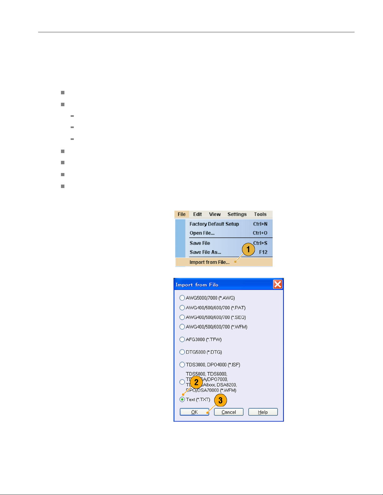
Importing Waveform Data
Data import functions allow you to use waveform data created outside the arbitrary waveform generator. You can import data
to create a new waveform or to replace existing waveform data.
The arbitrary waveform generator supports the following file formats:
*.AWG file created by Tektronix AWG5000 series or AWG7000 series
The following file formats created by Tektronix arbitrary waveform generators such as AWG400/500/600/700 series:
*.PAT
*.SEQ
*.WFM
*.TFW file created by Tektronix AFG3000 series arbitrary/function generator
*.DTG file created by Tektronix DTG5000 series data timing generator
*.WFM or *.ISF file created by Tektronix TDS/DPO series oscilloscope
Text file (*.TXT)
Refer to the online help system for more information about file import.
Saving and Recal
ling Setups
1. Select File > Import from File... to
display the Import from File dialog box.
2. Select the file format that you want to
import.
3. Click OK. The File Import dialog box,
such as shown in step 4, is displayed.
AWG5000B and AWG7000B Series Quick Start User Manual 43
Page 56

Saving and Recal
4. Select a file to import.
5. Select an import action in the Operation
frame.
ling Setups
Set to – Select the channel and index
number. The imp
data will be assigned to the specified
position.
Insert before – The imported
waveform data
before the specified cell of the
sequence. When the run mode is
non-sequenc
disabled.
Create Only – The imported
waveform will be added to the
Waveform Lis
orted waveform
will be inserted
e, this parameter is
t window.
Overwrite –
waveform data is overwritten.
6. If the imported w aveform data contains
information on sampling rate, amplitude,
or offset, you can select the attribute for
the waveform using the Change H/W
Setup.
For example, if you check the Sampling
Rate check box, the sampling rate will be
modified to reproduce the same signal
as the imported data.
7. Click Open.
When the import file format is *.AWG,
*.DTG, or *.TXT, a corresponding dialog
box is displayed.
When the import file format is other than
*.AWG, *.DTG, or *.TXT, the selected file
is imported and the waveform name(s)
are listed in the Waveform List window.
Specified existing
44 AWG5000B and AWG7000B Series Quick Start User Manual
Page 57

8. If the file format is Tektronix
AWG5000 series or AWG7000 series,
the AWG File Im
displayed.
Select a waveform to import.
9. Click OK. The selected waveform is
imported.
You can select multiple waveforms.
10. If the file format is Tektronix
DTG5000 se
lmport dialog box is displayed.
port dialog box is
ries, the DTG File
Saving and Recal
ling Setups
11. Assign each bit of imported
DTG5000 series block data (DTG
bits) to AW
Gbits.
AWG5000B and AWG7000B Series Quick Start User Manual 45
Page 58
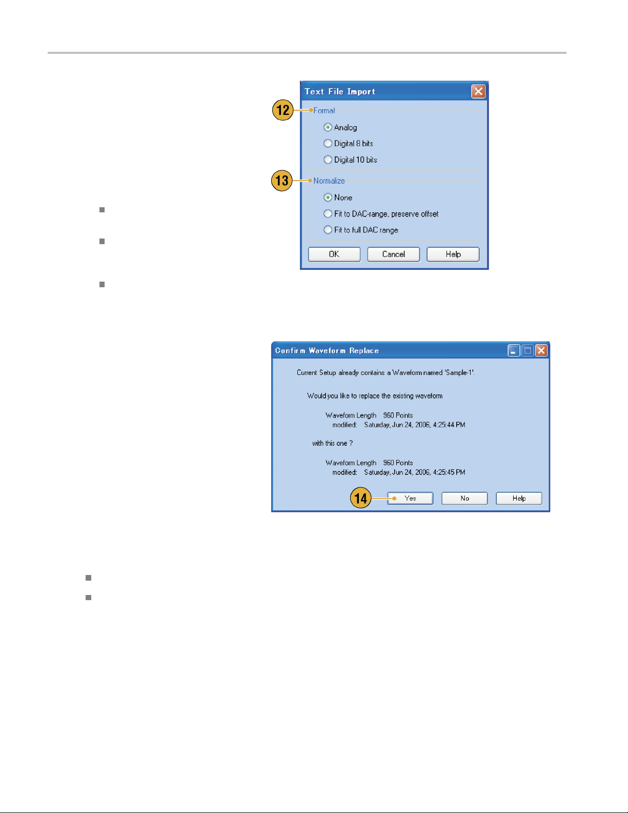
Saving and Recal
12. If text file format is selected, the Text File
Import dialog box is displayed. Select
the file format
Select Digital if you want to specify each
bit for DAC. If your instrument is an
AWG5000 serie
to 14 bits.
13. Select the normalize option using the
Normalize frame.
ling Setups
using the Format frame.
s, Digital format is fixed
None – The waveform data is not
normalized.
Fit to DAC Ran
– T he waveform data is scaled
relative to 0 (zero).
Fit to Full DAC Range –Minimum
value goes to
value and the maximum value goes
to +1.0 in normalized value.
14. This dialog box is displayed when you
execute import and the same name
waveforms a
or Yes to All if you want to replace the
waveform(s).
ge, Preserve Offset
-1.0 in normalized
lready exist. Select Yes
Quick Tips
When cr
By exec
46 AWG5000B and AWG7000B Series Quick Start User Manual
eating a new waveform, the name of the imported file will be the name of created waveform.
uting the file import function, the existing waveform is changed to be the same length as the imported file.
Page 59
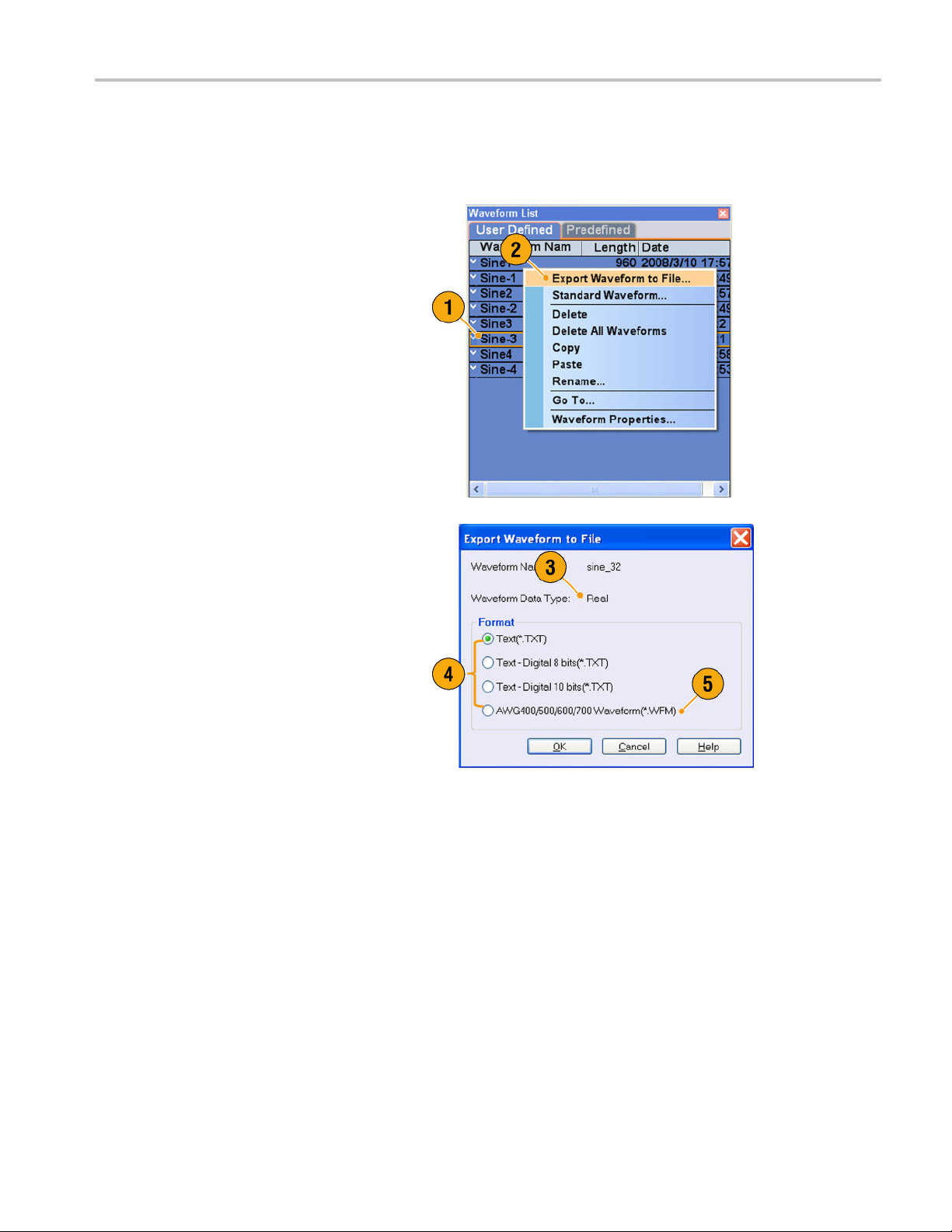
Exporting Waveform Data
The arbitrary waveform generator can export waveform data to a text file for use with other applications. You can also select
a pattern file or wave form file for use in AWG400/500/600/700 series instruments.
1. Select the waveform data for export.
You can select a waveform from the
Waveform List window.
2. Right click to display the popup menu.
Select Export Waveform to File... to
open the dialog box.
You can also select the Export Waveform
to File dialog box by right-clicking in the
Sequence or Waveform window.
Saving and Recal
ling Setups
3. This is an
you export a Real format waveform in an
AWG7000 series instrument.
4. Select a file format.
5. You can export a Real format
waveform
for AWG400/500/600/700 series
instruments.
example of a dialog box when
intoa*.WFMfile
AWG5000B and AWG7000B Series Quick Start User Manual 47
Page 60

Saving and Recal
6. This is an example of a dialog box when
you export an Integer format waveform
in an AWG7000 s
ling Setups
eries i nstrument.
7. You can select A
you select a *.TXT format. Select Digital
if you want to specify each bit for DAC.
8. You can export an Integer format
waveform into
AWG400/500/600/700 series
instruments.
9. Click OK. The Export dialog box shown
in step 10 is d
10. Select a location to save the waveform
data in Save in box.
11. The waveform name you selected in the
Waveform List window is displayed.
12. Click Save. You can export the selected
waveform data as a specified file format.
nalog or Digital when
a*.PATfile for
isplayed.
Quick Tips
Analog data is exported as normalized value.
You can select DAC resolution when an Integer waveform is exported. The selected DAC resolution is used to convert
integer data to normalized value.
To change waveform format (Real or Integer), use the Waveform Properties dialog box. (See page 55, Confirming
orm Properties.)
Wavef
48 AWG5000B and AWG7000B Series Quick Start User Manual
Page 61

Waveform Displa
y and Edit
Waveform Disp
Waveform Window
You can use the Waveform window to edit a newly created waveform or user-defined waveform listed in the Waveform List
window. A selected element in the Sequence window or a selected w aveform on the Ch n page of the Settings window is
displayed in the Waveform window.
1. This is an example of Graphic display.
Analog data and markers for Ch 1 and
Ch 2 are displayed.
2. Click this icon to toggle graphic display
and table display.
3. Click this icon (Vertical Best Fit) to adjust
analog channel height so that all the
elements a re contained in the Waveform
window.
lay and Edit
4. This is an example of Table display.
You can select either A nalog or Digital in
the Table display. This example shows
Digital display with binary format.
Quick Tips
You can select displayed items in the Waveform window from analog data only, marker data only, or analog and
marker data.
To remove waveform data from the Waveform window, select Edit > Clear from the menu bar.
You can select the vertical and horizontal units from the following using the Display Properties dialog box.
Vertical units – Voltage or Normalized Value
Horizontal units – Points or Time
AWG5000B and AWG7000B Series Quick Start User Manual 49
Page 62
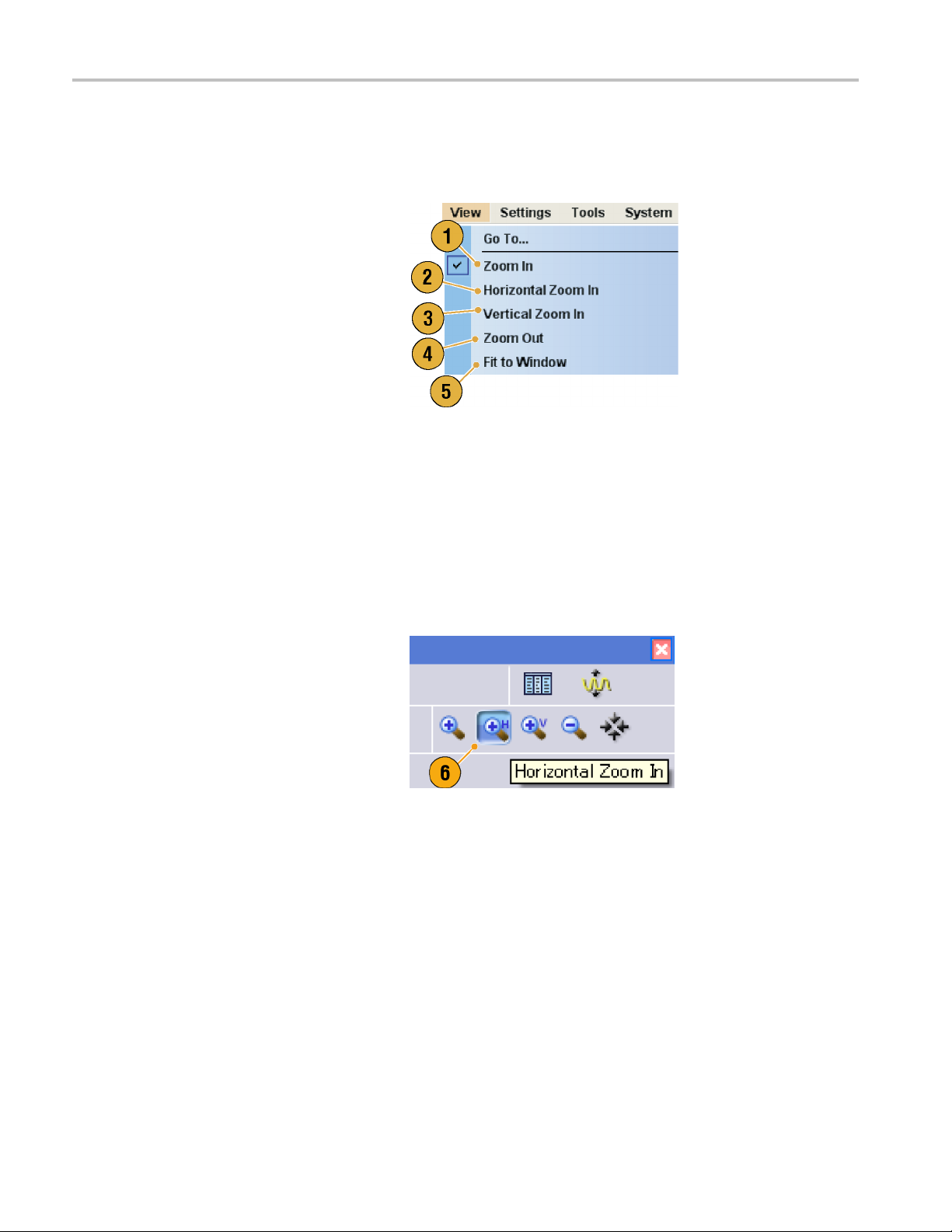
Waveform Displa
y and Edit
Using Zoom
Use Zoom when you want to temporarily look at details of a waveform. To magnify a waveform, select Zoom commands from
the View menu, or use the Zoom icons. The choices are as follows:
1. Zoom In –UseZoom In to magnify a
waveform horizontally and vertically at
the same time.
2. Horizontal Zoom In –UseHorizontal
Zoom In to magnify a waveform
horizontally.
3. Vertical Zoom In –UseVertical Zoom
In to magnify a waveform vertically.
You can select the vertica l scale
definition when zooming vertically.
Use the Preferences dialog box. (See
page 27, Setting the User Preferences.)
4. Zoom Out –UseZoom Out to return the
previous zoom factor. You can use Zoom
Out only after the waveform is magnified.
5. Fit to Window –UseFit to Window to fit
the waveform in the window and restore
the waveform to its state before the first
zoom in. You can use Fit to Window only
after the waveform is magnified.
6. The fastest way to set up a zoom display
is to use Zoom icons on the Waveform
window.
Select one of the Zoom icons, and then
click a nd drag across the segment of the
waveform to create a box for zooming, or
just click on a point in the waveform.
50 AWG5000B and AWG7000B Series Quick Start User Manual
Page 63
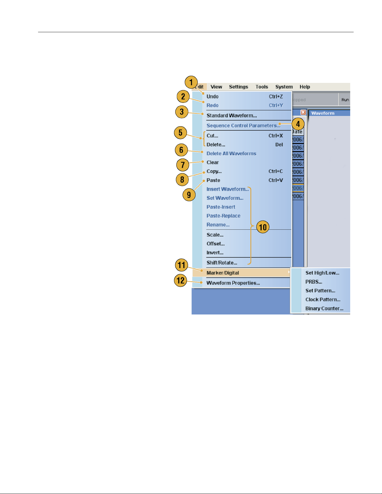
Creating or Modifying a Waveform
Use the Edit menu to create a new waveform or modify an existing waveform.
1. Select Undo to cancel the last process.
Undo does not apply to cursor position,
zoom, and scroll functions.
2. Select Redo to repeat the last process.
3. Opens the Standard Waveform dialog
box.
4. Opens the Sequence Control Parameters
dialog box.
5. Opens the Cut or Delete dialog box.
In the sequence, Cut or Delete causes
an immediate action.
6. Select Delete All... to delete all the
waveform data in the setup file.
7. Clear removes contents of selected
element(s) in the Sequence window.
Remaining elements do not shift.
In the Waveform window, Clear removes
the selected waveform data.
Waveform Displa
y and Edit
8. Opens the Copy dialog box.
In the sequence, Copy causes an
immediate action.
9. Select Paste to copy the content of
clipboard.
10. Opens edit-related dialog boxes.
11. Opens the Marker related submenu.
12. Opens Waveform Properties dialog box.
AWG5000B and AWG7000B Series Quick Start User Manual 51
Page 64
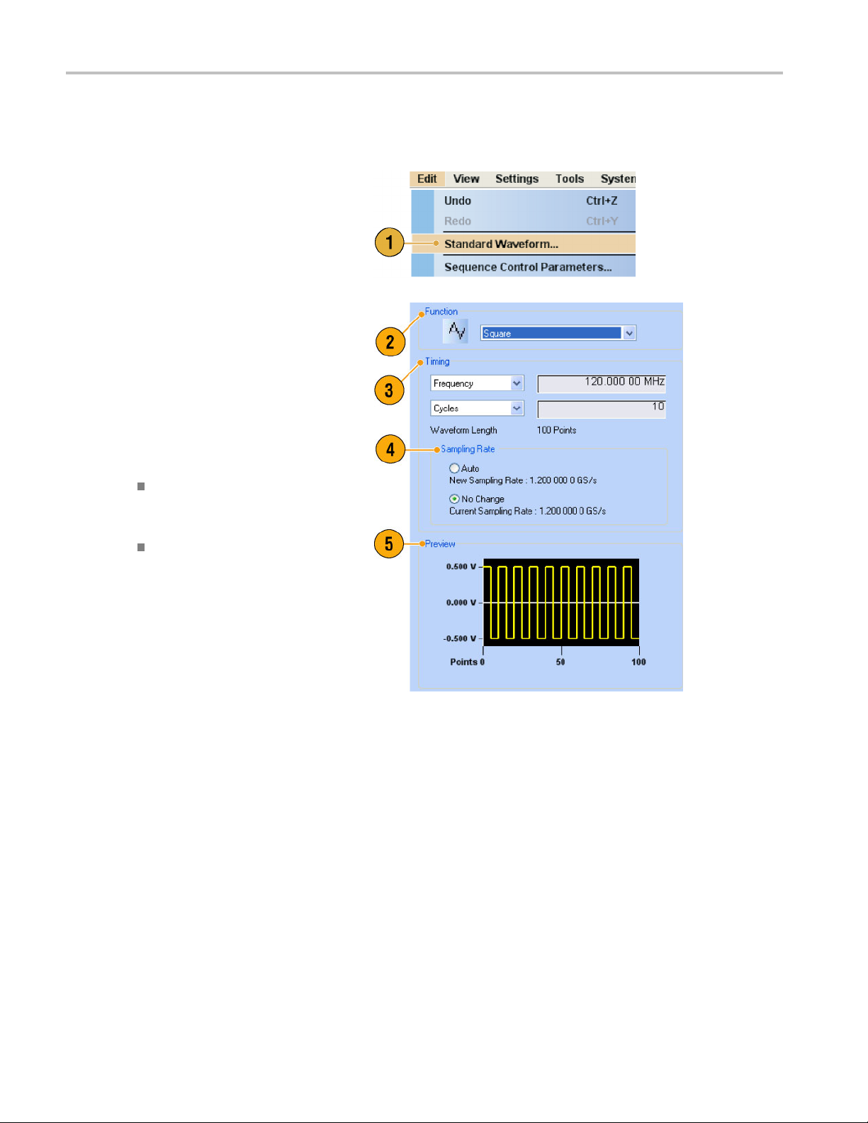
Waveform Displa
y and Edit
Creating a Standard Waveform
You can create a new waveform using the standard waveform dialog box.
1. Select Edit > Standard Waveform... to
open the Standard Waveform dialog box.
2. Use Function to select a waveform
type. You ca
Sine, Triangle, Square, Ramp, Gaussian
Noise, and DC.
3. Use Timing to set parameters for
Frequency,
Cycle.
4. Select Auto or No Change in Sampling
Rate.
n select a waveform from
Waveform Length, and
Auto Sampling rate and waveform
length are
appropriate values.
No Change Sampling rate is not
changed. You can select any
two param
waveform length, and cycle.
The remaining parameter will be
calculat
5. A wavefor
screen.
automatically set to
eters from frequency,
ed automatically.
m is displayed on the Preview
52 AWG5000B and AWG7000B Series Quick Start User Manual
Page 65

6. Use Level to set parameters for
Amplitude/Offset or High/Low.
7. Use Option to select the amplitude/
offset setting
when you set the vertical units to Voltage.
If you set the vertical units to Normalized
Value, this fr
page 28, Changing the Windows Display
Style.)
8. Select an edit action in the Operation
frame.
s. This frame is displayed
ame is disabled. (See
Waveform Displa
y and Edit
Set to – Speci
and index number. The created
waveform is assigned to the specified
position.
Insert befor
waveform is inserted before the
specified cell of the sequence. When
this comman
remaining data is shifted. When the
Run mode is non-sequence, this
parameter i
Create Only
waveform, but the waveform is not
loaded. Enter the waveform name
in the Wave
created waveform is listed in the
Waveform List window.
Overwrite – Specified existing
waveform
you select Overwrite, a waveform
currently being loaded is displayed in
the Targe
Waveform Name box is disabled.
fies the channel
e – The created
d is executed, the
s disabled.
– Creates a new
form Name box. The
data is overwritten. When
t Waveform Name box. The
9. Click Execute to create a waveform.
AWG5000B and AWG7000B Series Quick Start User Manual 53
Page 66
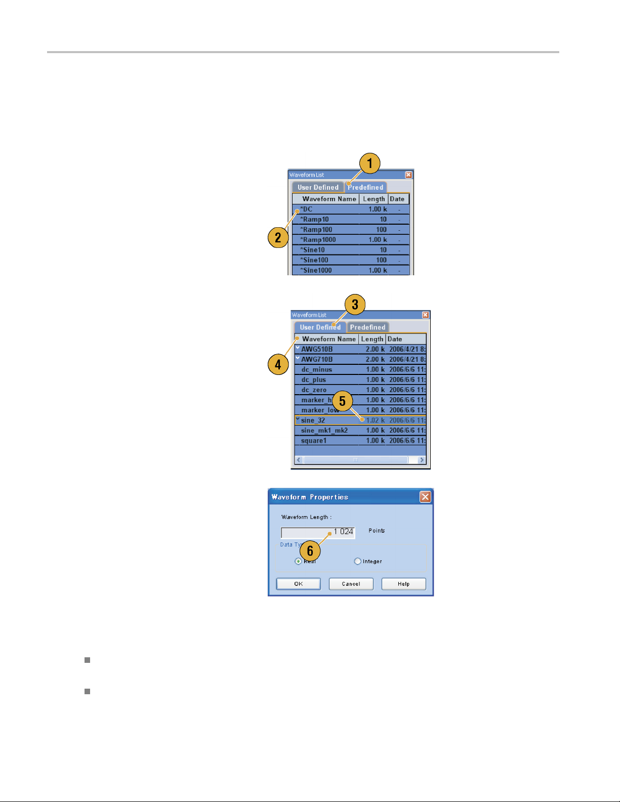
Waveform Displa
y and Edit
Accessing Waveform in a Setup File
A c reated waveform is registered as a user-defined waveform in the Waveform List window. The Waveform List window lists
the waveforms that are saved in the setup files (*.AWG). The instrument provides two types of waveform list (predefined
and user-defined).
1. To select a predefined waveform, click
the Predefined tab.
2. Predefined waveforms have an asterisk
sign (*) to the left of the waveform name.
NOTE. You cannot edit, delete, or rename
the predefined waveforms.
3. To select a user-defined waveform, click
the User Defined tab.
To edit a user-defined waveform,
select the waveform and drag it to the
Waveform window.
4. You can sort the waveform list by the
order of Waveform Name, Length, or
Date.
5. Each waveform length is displayed as a
three-digit number in the Waveform List
window.
6. If you want to know the exact waveform
length, select the waveform and then
right-click to display the pop-up menu.
Select Waveform Properties... to
display the Waveform Properties dialog
box. You can confirm the waveform
length with this dialog box.
Quick Tips
If you right-click on this window, a pop-up menu is display ed. You can access the commands, such as Delete, Copy, and
Paste.
When you create a waveform, you cannot use the same name as a predefined waveform.
54 AWG5000B and AWG7000B Series Quick Start User Manual
Page 67
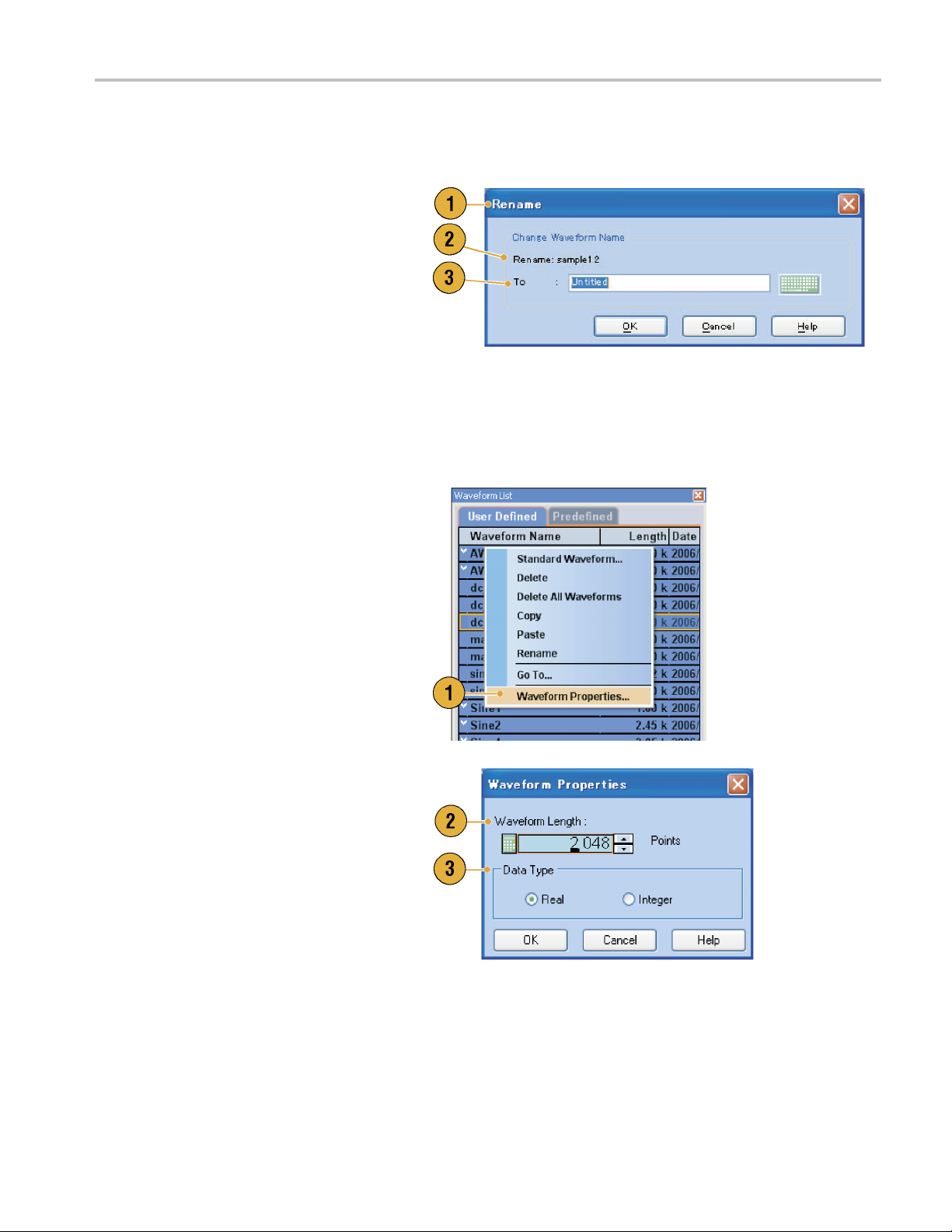
Changing Waveform Name
You can change a waveform name in the Waveform List window.
1. Select a waveform in the Waveform
List window, and then select Edit >
Rename... from the m enu bar to open
the Rename dialog box.
2. The waveform name is displayed.
3. Enter the new waveform name in the To
field.
Confirming Waveform Properties
You can confirm or change properties of waveform data using the Waveform Properties dialog box.
1. Select a waveform in the Waveform
List window, and then select Waveform
Properties... from the popup menu to
display the dialog box.
You can access the Waveform Properties
dialog box by right-clicking in the
Waveform window or the Ch n page of
Settings window.
Waveform Displa
y and Edit
2. You can c
length.
3. You can confirm or change the waveform
data type (Real or Integer).
AWG5000B and AWG7000B Series Quick Start User Manual 55
onfirm or change the waveform
Page 68

Waveform Displa
y and Edit
Editing a Waveform
You can edit a waveform which is created using the Standard Waveform dialog box, imported w aveform, or a user-defined
waveform listed in the Waveform List window.
Item and Range
When you edit a
1. To edit a waveform, y ou can use these
menu items.
2. You can select edit item(s) from the
following:
Ch n Analog da
Ch n Marker 1 d
All - Edit is a
can be target of an edit operation
such as Cut or Copy.
All Analog - Edit is applied to all
analog data
selected when Scale or Offset is
selected.
All Markers - Edit is applied to all
marker data
3. You can sel
following:
All - Edit is applied to all the range of
selected item(s).
waveform, items and range are usually specified as an edit target.
ta
ata/Marker 2 data
pplied to all items. All
. All Analog can be
.
ect edit range from the
Between Cursors - Edit is applied to
the range b
Selected -
range. This selection i s available
only in the Table display
NOTE. The internal clipboard resides in the instrument application software. It is different from Windows clipboard. You
cannot transfer data from other applications like Microsoft Excel i nto the instrument clipboard. Data transfer from other
applications is possible using the import/export functions.
56 AWG5000B and AWG7000B Series Quick Start User Manual
etween cursors.
Edit is applied to selected
Page 69

Waveform Displa
y and Edit
Cut and Paste Example
The following procedure shows Cut and Paste example in the Waveform window (Graphic display). You can also execute
Cut or Paste in the Table display.
1. Select the item(s) you want to edit. This
example shows cut and paste operation
using two channels.
2. Specify the range using cursors.
3. Select Edit > Cut... to open the Cut
dialog box. Select the following:
Items – Selected
Range – Between Cursors
If you need to change the Items or Range
settings, use this dialog box.
4. Click OK.
5. The selected portion of the waveform is
cut.
NOTE. If a part o f items are cut or deleted,
the waveform length will not be shortened.
The data is shifted. The portion after the
shifted area will be filled with default value.
NOTE. If all items are cut or deleted, the
waveform length is shortened accordingly.
AWG5000B and AWG7000B Series Quick Start User Manual 57
Page 70
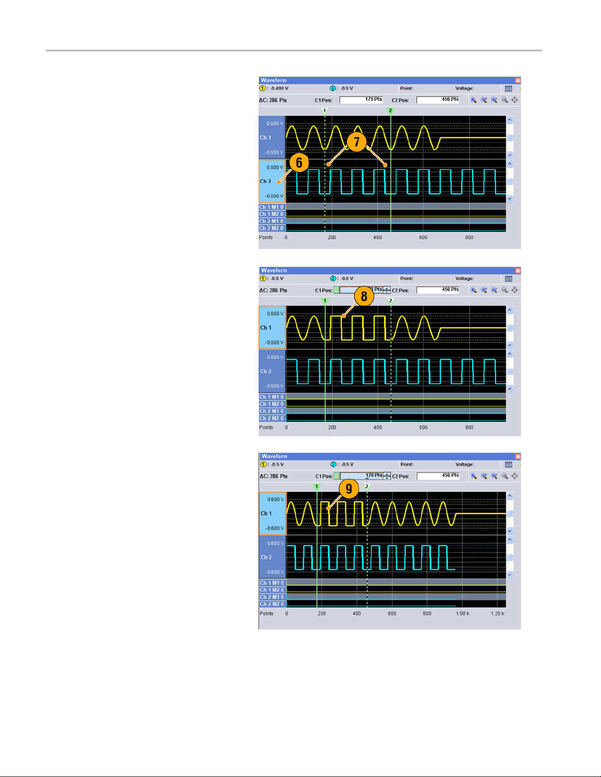
Waveform Displa
6. Select Ch 2.
7. Specify the edit target using the cursors.
From the Edit menu, select Copy.
y and Edit
8. This is an ex
ample of Paste-Replace.
The specified range of Ch 2 waveform is
pasted and replaces the Ch 1 waveform.
TheCh1wav
eform length is not
changed.
9. This is an example of Paste-Insert.The
specified range of Ch 2 waveform is
inserted on the Ch 1 waveform. The C h
1 waveform length is changed.
58 AWG5000B and AWG7000B Series Quick Start User Manual
Page 71

Math Waveforms
You can use the Math dialog box to perform mathematical operations on the waveform you are editing. The analog data of
two waveforms can be added, subtracted, or multiplied. The created waveform data can be added to the Waveform List.
1. Select Tools > Math... to display the
Math dialog box.
2. You can enter a waveform name in the
New Waveform field.
3. Select a waveform from the waveform
list. Click the icon to display the
Waveform List dialog box.
4. Select a math operator.
5. (AWG7000 series) Select the resolution.
6. If you click Show Preview,the
calculation results will appear on the
Preview screen.
Waveform Displa
y and Edit
7. Click OK to add the new waveform to the
Waveform List window.
Quick T
ips
A new waveform will be created as the result of waveform math operation. For the marker data, the data of the first
operand waveform will be copied to the new waveform.
The math operation is executed for all analog waveform data.
If the length of two waveforms is not the same, the length of the result is the same as the length of the shorter waveform.
The beginning part of the longer waveform is used for the calculation.
AWG5000B and AWG7000B Series Quick Start User Manual 59
Page 72

Waveform Displa
y and Edit
Normalize Option
You can select normalize options when analog data is normalized. Normalize is executed for the entire analog waveform data.
Select one of the following options from the
Tools menu:
1. Fit to DAC Range, Preserve Offset
The waveform data is scaled relative to
0(zero).
2. Fit to Full DAC Range
Minimum value goes to -1.0 in normalized
value and the m aximum value goes to
+1.0 in normalized value.
60 AWG5000B and AWG7000B Series Quick Start User Manual
Page 73

Using Other Edit Menu Commands
Scale. You can scale the specified range of analog data using Scale... from the Edit menu.
1. Vertical scale origin and scale factor can
be set. The scale factor does not have
the units.
2. Use this dialog box to change the Item or
Range. (See page 56, Item and Range.)
Waveform Displa
y and Edit
Offset. You c an add constants to the specified range of analog data using Offset... from the Edit menu.
1. Offset can be set by voltage or
zed value.
normali
2. Use this
Range. (See page 56, Item and Range.)
dialog box to change the Item or
AWG5000B and AWG7000B Series Quick Start User Manual 61
Page 74
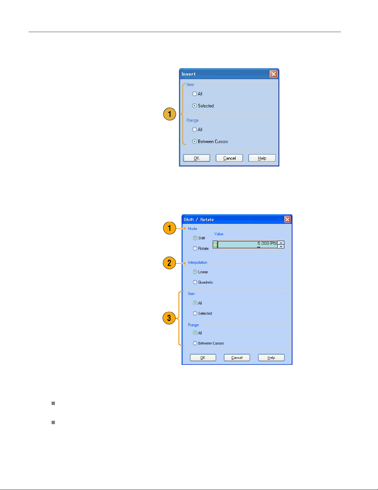
Waveform Displa
Invert. Data values in the specified range can be inverted using Invert... from the Edit menu.
1. For analog data, a positive value will
become negative. For m arker data, low
(0) becomes high (1).
Use this dialog box to change the Item or
Range. (See page 56, Item and Range.)
Horizontal Shift/Rotate. You can shift or rotate the specified range of waveform data horizontally using Shift/Rotate...
from the Edit menu.
y and Edit
1. Select Mode (
You can set the shift or rotate values
(time or points).
2. Linear or Quadratic interpolation can be
selected for
3. Use this dial
Range. (See page 56, Item and Range.)
Shift or Rotate).
fractional shift or rotation.
og box to change the Item or
Quick Tips
Horizontal Rotate is used to check if the waveform data is connected smoothly from the end of the first waveform to the
ing of the second waveform. This is especially useful when the w aveform is looped by the s equencer.
beginn
tal Shift/Rotate is applied for analog data and marker.
Horizon
62 AWG5000B and AWG7000B Series Quick Start User Manual
Page 75
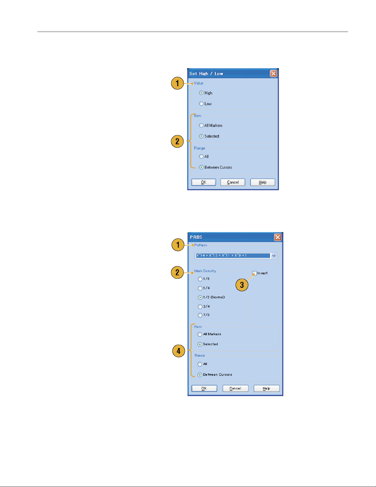
Waveform Displa
Set High/Low. You can set the specified range of marker data to high or low using Set High/Low... from the Edit >
Marker/Digita
1. Select High or Low.
2. Use this dialog box to change the Item or
Range. (See page 56, Item and Range.)
l menu.
y and Edit
PRBS. You
Marker/Digital menu.
1. Select a PRBS pattern.
2. Select a Mark Density.
3. Invert can be s et to On or Off.
4. Use this dialog box to change the Item or
Range. (
can replace a specified range of waveform data with a PRBS pattern using PRBS... from the Edit >
See page 56, Item and Range.)
AWG5000B and AWG7000B Series Quick Start User Manual 63
Page 76

Waveform Displa
Set Pattern. You can fill the specified area of marker data with a selected digital pattern using Set Pattern... from the
Edit > Marker/D
y and Edit
igital menu.
1. You can enter a
atextfile from the internal hard drive or
an external memory device.
The maximum le
1000.
2. If multiple items are specified as a target
for Set Pattern, the same data will be
filled in for a
and Range.)
pattern directly, or load
ngth of a bit pattern is
ll items. (See page 56, Item
Clock Pattern. You can fill a specified area of marker data with the 1010 clock pattern using Clock Pattern... from the
Edit > Marker/Digital menu.
1. Use this dialog box to change the Item or
Range. (See page 56, Item and Range.)
64 AWG5000B and AWG7000B Series Quick Start User Manual
Page 77
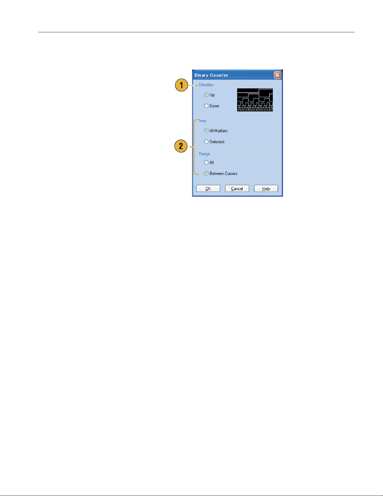
Waveform Displa
Binary Counter. You c a n fill the specified area of marker data with a binary counter pattern using Bina ry Counter...
from the Edit > M
1. You can select the direction (Up counter
or Down counter).
The up counter
down counter begins from all 1.
2. Use this dialog box to change the Item or
Range. (See page 56, Item and Range.)
arker/Digital menu.
begins from all 0, and the
y and Edit
AWG5000B and AWG7000B Series Quick Start User Manual 65
Page 78
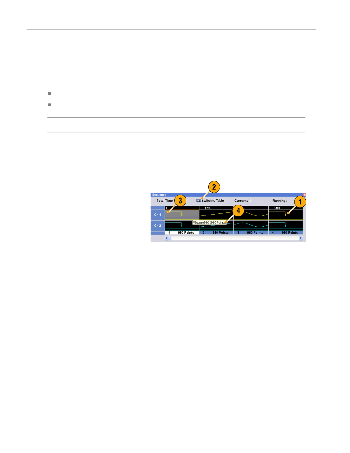
Sequence
Sequence
It is sometimes necessary to create long waveform files to fully implement a DUT test. Where portions of the waveforms are
repeated, a waveform sequencing function can save you a lot of memory-intensive waveform programming.
Sequence is used for mainly the following two purposes:
Output longer waveform than hardware m emory
Change the output waveform quickly (such as ATE applications)
NOTE. Wait Trigger is set to On in an instrument without option 08. To set Wait Trigger Off, option 08 must be installed in
the instrument.
Sequence Window
When Sequence is selected in the Run Mode, this window shows information on the status of the sequence settings.
(See page 22, Run Mode.)
1. This is an ex
window Thumbnail display.
2. Click Switch to Table to change the
display to Table display.
3. If you click on a cell, the selected
waveform is
window. The background color of the
selected cell changes.
4. If you hover the mouse over a sequence
cell, a too
waveform name and waveform length.
ample of the Sequence
displayed in the Waveform
ltip appears to show you the
66 AWG5000B and AWG7000B Series Quick Start User Manual
Page 79

5. This is an example of Table display.
6. You can directly enter a sequence
parameter value, such as Repeat count
or Go To target,
in the Table display.
Quick Tips
The following methods are available for applying an existing waveform to a sequence:
Drag a waveform from the Waveform List window to a cell of the Sequence window
After selecting a cell in the Sequence window, use Set Waveform... or Insert Waveform... from the Edit menu
When Continuous, Triggered, or Gated is selected in the Run mode, the Sequence window is hidden.
The following icons are used in the Sequence window:
Sequence
Display Icons Description
Wait Trigger
Repeat. (Repeat count is set to 26 in this example.)
Repeat (Infinite)
Event Jump. (Jump target is set to index number 26 in this example.)
Go To. (Go To target is set to index number 26 in this example.)
AWG5000B and AWG7000B Series Quick Start User Manual 67
Page 80

Sequence
Creating a Sequence
To create a sequence, waveforms must be assigned to Sequence w indow. The following example shows basic steps to
create a sequence.
1. Select a waveform in the Waveform List
window.
2. Drag and drop the waveform to a
sequence window cell.
As a quick access to the waveform list,
you can double-click or right-click on a
cell.
3. After assigning waveforms to sequence
cells, you can define the sequence
parameters.
Right-click on a c ell, or use the Edit
menu to open the Sequence Control
Parameters dialog box.
4. The sequencer will wait for the trigger
before generating a waveform if Wait
Trigger is checked.
5. A waveform can be repeated if the
Repeat Count is specified for each
element of the sequence.
6. Event Jump To changes the sequencing
of the waveform by the external event.
See the Quick Tips below for supported
event signals.
7. If you specify Go To target for each
sequence element, the sequencer
jumps to the element specified by Go
To target immediately after generating
the waveform specified in a sequence
element.
68 AWG5000B and AWG7000B Series Quick Start User Manual
Page 81
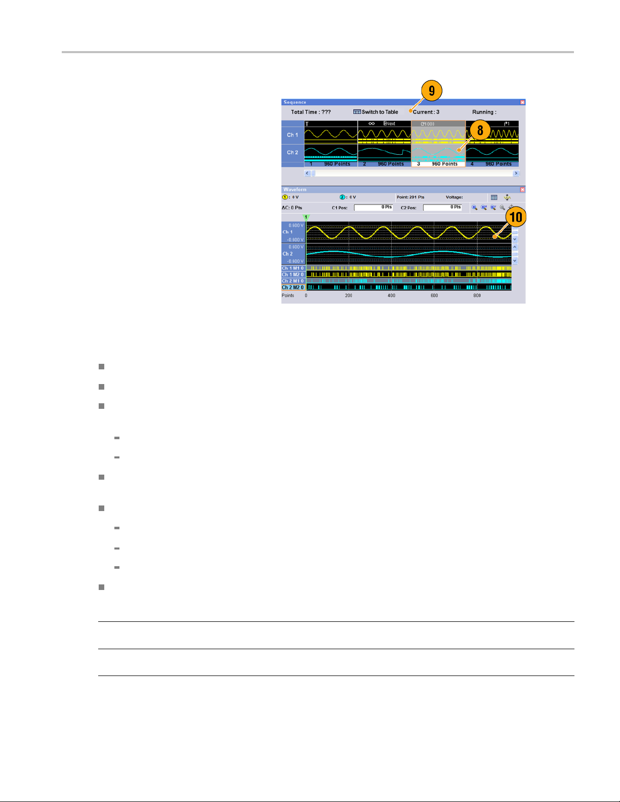
8. A sequence element consists of all
analog waveform data and marker data
with an index n
umber.
Sequence
9. A selected elem
element.
10. A selected element in the Sequence
window will be displayed i n the Waveform
window.
ent is called current
Quick Tips
You can use the Standard Waveform dialog box to create a waveform and set the waveform to Sequence window.
When importing waveform data, you can directly set the waveform to Sequence window.
If Sequence is selected in the Run mode, the sequencer executes the sequence definition. Sequence definition consists
of a series of sequence elements. Each sequence element has the following information:
References to the waveform for each channel
Sequence control parameters (Wait, Repeat, Event Jump To and G o To)
Sequence is executed in turn from the first element (Element Index = 1) to the last element. If an element has Jump To or
Go To, the
The follo
Maximum s
Instrument type Maximum sequence length
AWG7061B, AWG7062B, AWG7121B,
AWG7122B
AWG5002B, AWG5004B, AWG5012B,
AWG5014B
sequencer follows that definition.
wing signals are supported as an event:
A signal i
The front
Remote co
s applied to the front-panel Event Input connector
-panel Force Event button is pushed
mmand is received – EVENt[:IMMediate]
equence length is different depending on the instrument type.
1 to 16,000 steps
1 to 8,000 steps
AWG5000B and AWG7000B Series Quick Start User Manual 69
Page 82

Sequence
NOTE. There are two sequencer modes in the arbitrary waveform generator to execute the created sequence: the hardware
sequencer mode
hardware and software sequencer modes.
and the software sequencer mode. Refer to the online help for details about the difference between the
Editing a Sequ
The following commands are provided for sequence edit:
Set Waveform and Insert Waveform. Use these menus to set or insert a waveform to a Sequence window cell.
Clear. Clear removes the contents of selected element(s). You can clear multiple non-contiguous elements. Unselected
elements do not shift.
Cut and Delete. Cut and Delete can be done by the units of element. You can cut or delete multiple and continuous
elements at
Copy, Paste-Insert and Paste-Replace. You can copy or paste data on one or more contiguous elements. The
data in the clipboard will be inserted or replaced at the specified position of the sequence. If Paste-Insert is executed,
the existing data is shifted.
Edit Example
The following procedure shows Cut and Paste example in the Sequence window (Table display).
1. Create a sequence.
atime.
ence
2. Select t
NOTE. Y
of element level.
70 AWG5000B and AWG7000B Series Quick Start User Manual
he element(s) to cut. In this
example, Index number 3 is the target
of Cut.
ou can Cut and Delete at the units
Page 83

3. Cut is executed and the remaining data
in the sequence are shifted.
Sequence
NOTE. Cut data i
Deleted data is removed from the sequence
and cannot be recovered.
4. Clear initializes the data of selected
waveform(s
cell becomes Empty.
5. Use Insert
waveform from the Waveform List.
6. You can use Paste-Insert or
Paste-Replace when you want to
set a wave
waveform in the Sequence window.
s placed in the clipboard.
) or element(s). A cleared
Waveform... to insert a
form after copying any
AWG5000B and AWG7000B Series Quick Start User Manual 71
Page 84

Sequence
Event Jump
Use the Event page of Settings window to set parameters for event signal. You can use the Event page when the Run
mode is Sequence.
1. Sets external event input threshold level.
2. Selects the polarity of external event
input signal (Positive or Negative).
Positive – Jump will occur when the
instrument receives a positive pulse.
Negative – Jump will occur when
the instrument receives a negative
pulse.
3. Sets jump timing (Async or Sync).
Async – Jump will occur immediately.
Sync – Jump will occur after the
waveform is generated.
4. Sets event input impedance (1 kΩ or
50 Ω).
Quick Tips
Event Jump c
Jump timing
an change the sequence order using an event signal.
is applied to both Event Jump and Force Jump.
72 AWG5000B and AWG7000B Series Quick Start User Manual
Page 85

Force Jump To
Force Jump allows you to jump to a position that you choose while the instrument is outputting a sequence.
Select System > Force Jump To... to open
the Force Jump To dialog box.
1. Specify a jump target or select Index No.
2. When Index No is selected as jump
target, enter the index number using the
Value: field.
3. Click Jump Now to change the w aveform
output to the position specified by jump
target.
Quick Tips
The arbitrary waveform generator has an Event Jump function which changes the sequence using an event signal. Use
the Event page of the Settings window to set parameters for Event Jump.
Sequence
Force Jump is similar to Event Jump. In the case of Force Jump, you must specify the jump target explicitly by using the
ForceJumpTodialogbox.
Force Jump is independent from Event Jump. Force Jump can be executed regardless of the Event Jump setting.
AWG5000B and AWG7000B Series Quick Start User Manual 73
Page 86

Sequence
Accessing Sequence Elements Outside the Display Area
When you create a long sequence, the Sequence window cannot di splay the whole sequence elements. You can use the Go
To dialog box to move to a specified element that is not displayed in the window.
1. After creating a sequence, select View
> Go To... or select Go To... from the
popup menu.
Thedialogboxshowninstep2is
displayed.
2. Select Index No as a Go To target.
3. Enter a value.
4. Select OK intheGoTodialogbox.The
display will jump to the specified position.
Quick
Tip
You can also use the Go To dialog box in the Waveform or Waveform List window.
74 AWG5000B and AWG7000B Series Quick Start User Manual
Page 87

Tutorials
The examples in this section show how to use your instrument to do common arbitrary waveform generator tasks. These
examples use the dual-channel model.
Creating and Editing a Waveform
1. Recall the default s etup.
2. Select Continuous from the Run Mode
page of the Settings window.
Tutorials
3. Use the Standard Waveform dialog box
to create the following square waveform:
Waveform Length: 960 points
Cycles: 5
Amplitude: 1.0 V p-p
Offset: 0.5 V
4. Set the waveform created in step 3 to
Ch 1.
5. Assign the waveform name “Ch1-Square”
to the waveform.
AWG5000B and AWG7000B Series Quick Start User Manual 75
Page 88

Tutorials
6. Use the Standard Waveform dialog
box to create the sine waveform shown
below:
Waveform Lengt
Cycles: 3
Amplitude: 1.
Offset: -0.5 V
7. Set the wavefo
Ch 2.
8. Assign the waveform name “Ch2-Sine”
to the waveform.
9. To edit analog waveform data, hide the
Ch1andCh2Marker data using the
Display Properties dialog box.
h: 1024 points
0Vp-p
rm created in step 6 to
10. Delete points from the end of the Ch 2
waveform to make it the same length as
the Ch 1 waveform.
Use cursors to set the range.
76 AWG5000B and AWG7000B Series Quick Start User Manual
Page 89
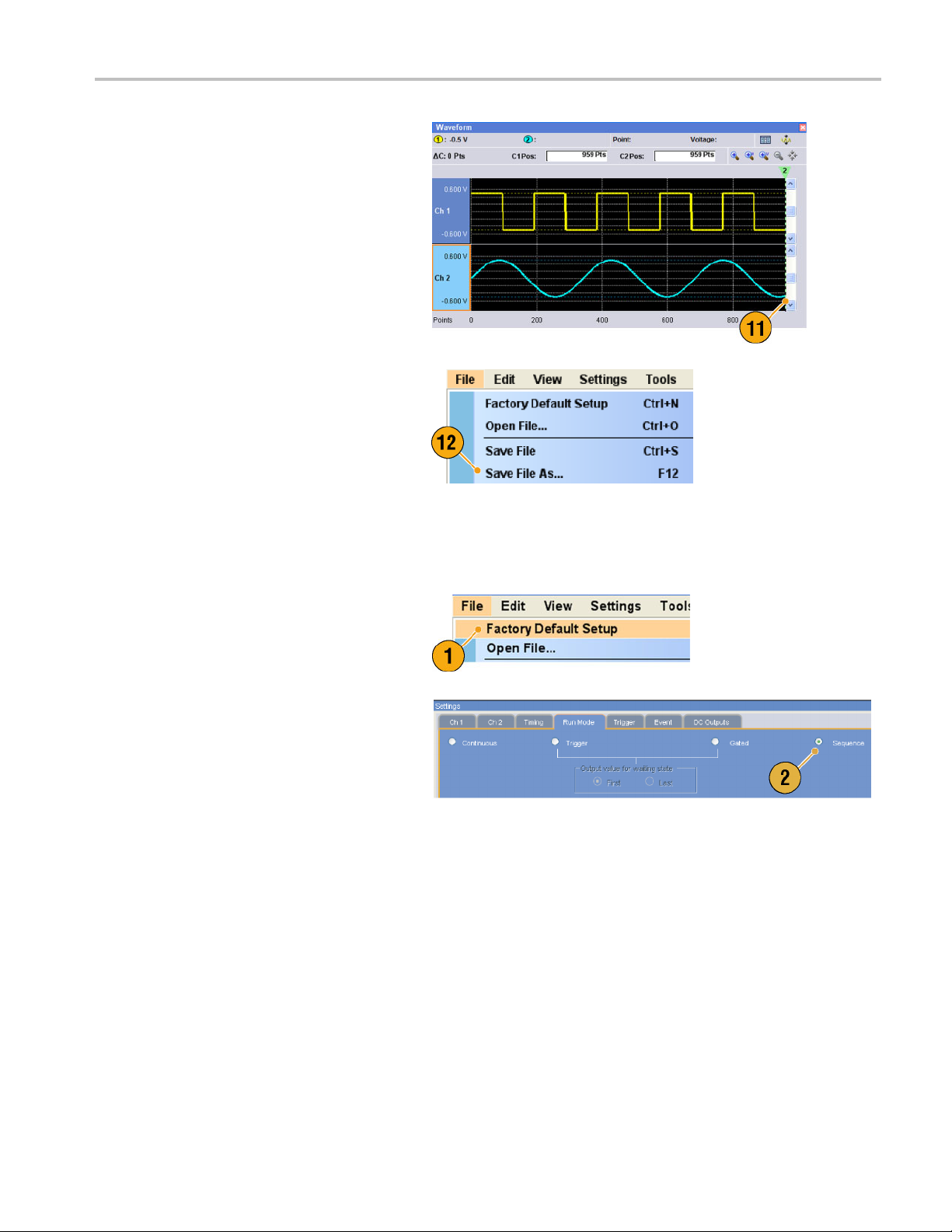
11. Ch 1 and Ch 2 waveforms have the
same waveform length. You can now
output the sig
12. Save the setup.
nal.
Tutorials
Creating and Editing a Sequence
1. Recall the default s etup.
2. Select Sequence from the Run Mode
page of the Settings window.
AWG5000B and AWG7000B Series Quick Start User Manual 77
Page 90
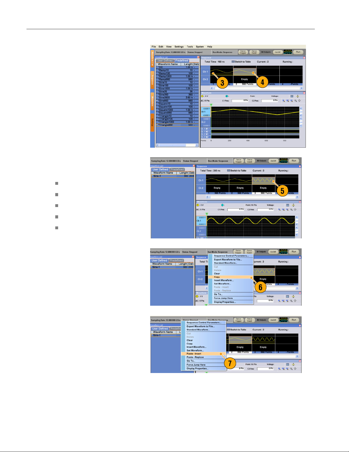
Tutorials
3. Select *Sine960 from the Predefined
page of the Waveform List window,
and drag and dr
Ch 1 sequence.
4. In the same way, select *Triangle960
from the Waveform List w indow, and
set the wavefo
Ch 1 sequence.
5. Create a sine waveform with the following
attributes and set the waveform to the
third cell of Ch 1 sequence.
Waveform Length: 960 points
op it to the first cell of
rm to the second cell of
Cycles: 5
Amplitude: 1.0 V p-p
Offset: 0.0 V
Waveform Name: Sine-1
6. Select third cell of sequence, and select
Copy fro
7. Selec
select Paste-Insert from the popup
menu.
m the popup menu.
t second cell of sequence, and
78 AWG5000B and AWG7000B Series Quick Start User Manual
Page 91
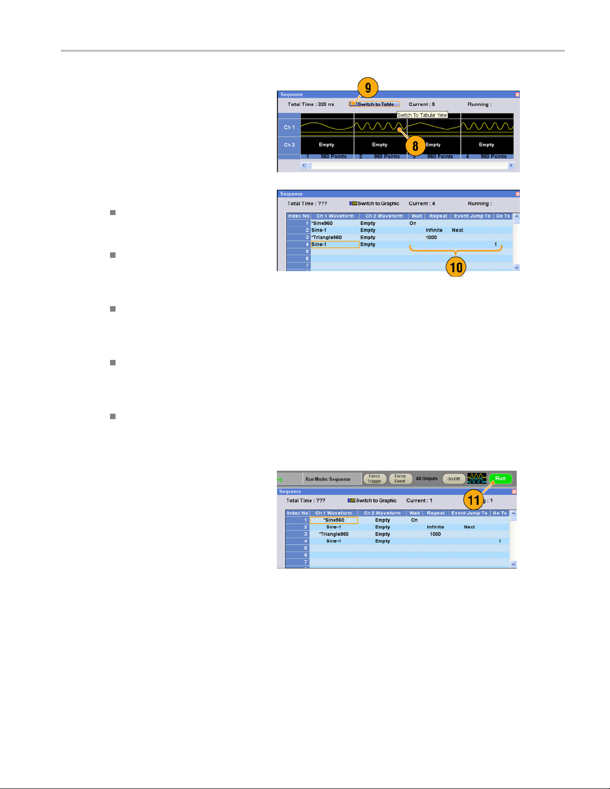
8. The copied waveform is pasted to
index 2.
9. Click the Switch to Table icon to change
the display to T
abular view.
Tutorials
10. Set the follo
Index 1: Wait
Index 2: Repeat count Infinite
Index 2: Event Jump To Next
Index 3: Repeat count 1000
Index 4: Go To 1
11. Click the Run button to confirm that the
sequence w
window next to the Run button will be
activated when the instrument is in the
running st
wing sequence parameters:
Trigger On
The sequence waits for a trigger
before generating the first element.
The sequence
the Sine-1 waveform until an event
occurs.
When the inst
event signal, the sequence jumps to
next element.
The sequence
*Triangle960 waveform 1000
times.
The sequenc
number 1 after generating index
number 4 waveform.
ate.
infinitely generates
rument receives an
repeats the
e jumps to index
orks properly. The animation
AWG5000B and AWG7000B Series Quick Start User Manual 79
Page 92

Tutorials
80 AWG5000B and AWG7000B Series Quick Start User Manual
Page 93

Index
Index
Symbols and Numbers
10 MHz Reference Output
Rear panel, 14, 15
A
Accessing con
Accessing menus, 23
Accessories, 1
Add Input
Rear panel, 15
All Outputs On/Off button
Front panel, 30
Status bar, 26
Analog Output connector
Front panel, 13
Arbitrary waveform generator
Basic steps, 21
trol windows, 23
B
Binary Counter
Edit menu, 65
C
Calibration, 8
Channel Coupli
Settings menu, 34
Channel page
Settings windo
Channel Skew
System menu, 35
Cleaning, 2
Clear
Edit menu, 51
Sequence window
Waveform window, 49
Clock Pattern
Edit menu, 64
Configuration Utility dialog box, 6
Continuous
Run mode, 22
Control panel, 16
Control settings
How to change, 24
Control windows
Display/Hide, 25
Creating O S restor
ng
w, 31
, 70, 71
eCD-ROMs, 11
Current element, 69
Cut example
Waveform wind
ow, 57
D
DAC Resolution
Export waveform data, 48
Settings wind
DC Output connector
Front panel, 13
DC Output page
Settings window, 32
Default setup, 42
Diagnostics, 7
Digital output, 38
Direct Output, Settings window, 32
Display Proper
Divider Rate, 33
Documentation, vii
ow, 31
ties dialog box, 28
E
Edit example
Sequence window, 70
Edit menu
Overview, 51
Sequence, 70
Element, Sequence, 69
Event Input conn
Front panel, 13, 69
Event Jump, 73
Event Jump To
Sequence control
Event page
Settings window, 72
Export waveform data, 47
External Clock In
Rear panel, 14, 15
ector
parameter, 68
put
F
Factory Default
Startup setting,
File menu
Overview, 39
42
Force Event button
Front panel, 69
Status bar, 26
ForceJumpTo
System menu, 73
Force Trigger b
Status bar, 26
Front panel, 13
Front panel con
Lock/unlock, 17
utton
trols
G
Gated
Run mode, 22
Go To
Sequence control
parameter, 68
Go To dialog box
View menu, 74
GPIB connector
Rear panel, 14, 15
GPIB/LAN Configuration
System menu, 5
H
Hardware sequencer, 69
Help Language
Preferences dia
Hold
Preferences dialog box, 27
log box, 27
I
Icons
Sequence window, 67
Zoom, 50
Import waveform
AWG file format, 45
DTG file format, 45
Text fi le format, 4
Incoming inspection, 7
Insert Waveform
Sequence window,
Integer
Waveform format, 40, 48
Integer format
Export waveform data, 48
data, 43
6
70
AWG5000B and AWG7000B Series Quick Start User Manual 81
Page 94

Index
Interleave adjustment
System menu, 37
Interleave Output connector
Front panel, 13
Interleaving, 36,
Invert
Edit menu, 62
Item, Edit menu,
37
56
L
LAN connector
Rear panel, 14, 15
Last Used File
Startup setting, 42
LCD Brightness
Preferences dial
Lock/unlock
Front panel controls, 17
og box, 27
M
Marker output
With interleave on, 36
Marker Output connector
Front panel, 13
Math
Tools menu, 59
Maximum sequence
Menu bar
Screen interface, 20
Multiplier Rate, 3
length, 69
3
N
Network connection, 4
Normalize
Tools menu, 60
O
Offline mode, 6
Offset
Edit menu, 61
Online help, 19
Operating requirements, 2
Option Installati
System menu, 10
OS restore CD-ROMs, 11
Oscillator Output
Rear panel, 15
Output on/off, 30
Overheat protectio
on
n, 9
P
Paste-Insert
Sequence window, 70
Waveform windo
Paste-Replace
Sequence window, 70
Waveform window
Pop-up keypad, 24
Power supply, 2
Power-on self te
Power-on settings, 42
PRBS
Edit menu, 63
Predefined waveforms
Waveform List window, 54
Preferences dial
Programmer online help, 19
w, 58
,58
st, 7
og box, 19, 27
R
Range, Edit menu, 56
Raw Socket
GPIB/LAN Configuration, 5
Real
Waveform format, 40,
Real format
Export waveform data, 47
Rear panel
AWG5000 series, 15
AWG7000 series, 14
Recalling instrume
Reference Clock Input
Rear panel, 14, 15
Remote command bar
Screen interface, 20
Remote Command Log
Preferences dialog
Remote PC
Controlling the i nstrument, 6
Rename
Edit menu, 55
Repeat
Sequence control
parameter, 68
Repetition Rate, 33
Restore Operating Sy
Run button
Front panel, 30
Status bar, 26
Run Mode page
Settings window, 22
Run state control, 30
nt setup, 41
box, 27
stem, 11
48
S
Safety Summary, iii
Saving instrum
Scale
Edit menu, 61
Screen interfac
Self calibration, 8
Sequence
Edit menu, 66
Run mode, 22
Tutorials, 77
Sequence Contro
box, 68
Sequence definition, 69
Sequence elemen
Sequence length, 69
Sequence window, 66
Screen interface
Set High/Low
Edit menu, 63
Set Pattern
Edit menu, 64
Set Waveform
Sequence menu, 68
Sequence window, 70
Settings window
Screen interface,
Shift/Rotate
Edit menu, 62
Software sequencer
Specifications, Help menu, 19
Spin buttons, 24
Standard accessori
Standard waveform
Edit menu, 52
Tutorials, 75
Status bar, 26
Screen interface, 20
ent setup, 40
e, 20
l Parameters dialog
t, 69
,20
20
,69
es, 1
T
Timing page
Settings window, 33
Tooltip, 66
Touch screen, 18
Trigger Input connector
Front panel, 13
Trigger page
Settings window, 22
Triggered
Run mode, 22
82 AWG5000B and AWG7000B Series Quick Start User Manual
Page 95

Index
Tutorials
Sequence, 77
Standard waveform, 75
U
USB connector
Front panel, 13
Rear panel, 14, 15
User Default File
Startup setting
User online help, 19
User Preferences
System menu, 27
User-defined waveforms
Waveform List window, 54
,42
V
VXI-11 Server
GPIB/LAN Configuration, 5
W
Wait Trigger
Sequence control
parameter, 68
Waveform data
Export, 47
Import, 43
Waveform data format
Saving an instrument setup, 40
Waveform proper
Waveform length
To change, 55
Waveform List win
Screen interface, 20
Waveform name
To change, 55
Waveform Properties
Confirming waveform
length, 54
Edit menu, 55
ties, 55
dow, 54
Waveform Rotation
Settings Windo
Waveform window, 49
Screen interface, 20
Window tag
Screen interface, 20
w, 32
Z
Zeroing, 36
Zoom, 50
AWG5000B and AWG7000B Series Quick Start User Manual 83
 Loading...