

Page 1

xx
AWG70000 Series
ZZZ
Arbitrary Waveform Generators
Printable Help Document
*P077144600*
077-1446-01
Page 2

Page 3

AWG70000 Series
Arbitrary Waveform Generators
ZZZ
Printable Help D ocument
w.tek.com
ww
077-1446-01
Page 4

Copyright © Tektronix. All rights reserved. Licensed software products are owned by Tektronix or its
subsidiaries or suppliers, and are protected by national copyright laws and international treaty provisions.
Tektronix products are covered by U.S. and foreign patents, issued and pending. Information in this
publication supersedes that in all previously published material. Specifications and price change privileges
reserved.
TEKTRONIX and TEK are registered trademarks of Tektronix, Inc.
Microsoft, Windows are registered trademarks of Microsoft Corporation.
MATLAB is a registered trademark of The Mathworks, Inc.
Supports Product Software Version 7.x and above.
Help part number: 076–0424–00
PDF of Help system part number: 077–1446–00
Contacting Tektronix
Tektronix, Inc.
14150 SW Karl Braun Drive
P. O . B o x 5 0 0
rton, OR 97077
Beave
USA
For product information, sales, service, and technical support:
In North America, call 1-800-833-9200.
Worldwide, visit www.tek.com to find contacts in your area.
Page 5

Table of Contents
Introduction
Introduction ......................................................................................................... 1
Product software .................................................................................................... 2
Documentation........... .................................. ................................ ......................... 2
Support information..... .................................. ................................ ......................... 3
Analysis and connectivity support ........................... .................................. ................... 4
WorkingwiththeAWG
AWG mode window
AWG mode general overview ......... ................................ ................................ ....... 5
AWG workspace tabs.......................................................................................... 6
Run state control .............................................................................................. 16
Screen interface features via touchscreen and mouse..................................................... 16
Toolbar ............. .................................. ................................ .......................... 20
Waveform list
Working with the waveform list..................................... ................................ ........ 22
Adding a waveform......................... ................................ ................................ .. 24
Saving a waveform ..................... ................................ ................................ ...... 29
Apply corrections............................................................................................. 30
Assign a waveform to a channel ............................................................................ 30
Modify waveform............................................................................................. 32
Modify markers . ................................ ................................ .............................. 36
Waveform properties ... ................................ ................................ ...................... 39
Applying waveform corrections
Applying Sin(x)/x corr
Applying correction file................................................................................. 41
Apply S-Parameters
Apply S-Parameters...................................................................................... 43
S-Parameter file descriptions....................................................................... 46
Aggressor signals ................................................................................... 48
Sequence list
Sequence list .................................................................................................. 48
Adding a sequence............................................................................................ 49
Saving a sequence ............................................................................................ 51
Assigning tracks to a channel................................................................................ 51
Edit a sequence................................................................................................ 54
Sequence properties ...................................... ................................ .................... 55
General setup
Table of Contents
ection ......... .................................. ................................ 41
AWG70000 Series Arbitrary Waveform Generators Printable Help Document i
Page 6

Table of Contents
General setup overview ...................................... ................................ ................ 56
Enable dynamic loading.......................................... ................................ ............ 56
Enable all channels on play.. ................................ ................................ ................ 57
Apply recommended settings on assignment .................................. .. .. . . . . . . . . . . . . . . . . . . . . . . . . 57
Channel setup
Channel setup introduction .................................................................................. 57
Enable outputs / relay state .................................. ................................ ................ 58
Channel output path .......................................................................................... 59
Amplitude ..................................................................................................... 62
Markers ........................................................................................................ 64
Resolution (bits) .............................................................................................. 65
Couple channel settings (AWG70002) ..................................................................... 65
Channel color.... ................................ .................................. ............................ 67
Filter and Range (Option AC only) ......................................................................... 68
Output Options
Option AC Advanced settings
Clock setup
Clock introduction ............................................................................................ 72
Sample Rate ................................................................................................... 73
Clock and Reference Sources ............................................................................... 73
Clock and sync outputs......................... ................................ .............................. 77
Trigger setup
Trigger control .................................. .................................. ............................ 77
Trigger input settings .. . . . . . . . . . . . . . . . . . . . . . . . . . .............................................................. 79
Trigger timi
Skew setup
Adjust skew ................................................................................................... 84
Aux Out setup
Aux Out setup ......................... ................................ .................................. ...... 89
Timer
Timer setup .. .................................. ................................ ................................ 90
Sync (Synchronization hub)
Using synchronization........................ .................................. .............................. 91
Sync hub connections ............ ................................ .................................. .......... 92
Enable and configure synchronization...................................................................... 95
Deskew calibration
Direct ................ .................................. ................................ .................... 60
AC ......................................................................................................... 60
DC Amplified............................................................................................. 61
Output Options........................................................................................... 68
AC Advanced amplitude adjustment (Option AC)......... .. . . . . . . . . . . . . . . . . . . . . . . . . . . . . . . . . . . . . . . . . 70
ng ................................................................................................. 82
Deskew calibration................................... .................................. .................. 98
ii AWG70000 Series Arbitrary Waveform Generators Printable Help Document
Page 7

Table of Contents
Calibration messages
Calibration recommended messages................................................................. 101
Streaming ID
Streaming ID ................................................................................................ 101
Protocols
Protocol description.................................................................................... 102
Configure status acknowledgements........... ................................ ...................... 103
Configure status messages ............................................................................ 103
Sequencer control messages .......................................................................... 105
Status messages .......... ................................ ................................ .............. 106
Reset..................................................................................................... 108
Sequence Editor
Sequence tab overview....................... .................................. ............................ 108
Sequences - creating and editing
Editing tools ............ ................................ .................................. .............. 109
Sequence create and edit toolbar ............. .................................. ...................... 111
Copy and paste guidelines .................. ................................ .......................... 115
Sequence settings
Sequence settings . . . . . . . . . . . . . . . . . . . . . . . . . . . . . . . . . . . . . . . . . . . . . . . . . . . . . . . . . . . . . . . . . . . . .................. 115
Forcing jumps
Forcing jumps introduction ... ................................ ................................ ........ 116
Force Jump To... button ............................... ................................ ................ 117
Force jump here........................................................................................ 119
Forcing a jump (with Synchronization Hub)........................................................ 119
Jump timing
Jump timing ............................................................................................ 120
Pattern jump
Creating a Pattern jump ............................................................................... 120
Jump priority
Jump executi
Flags
Sequence flags.......................................................................................... 123
Subsequence editing
Subsequence editing ............................... .. .. .. . . . . . . . . . . . . . . . . . . . . . . . . . . . . . . . . . . . . . . . . . . . . . . 125
Sequencer batch compiler
Sequencer batch compiler........................... ................................ .................. 126
Capture and Playback
Capture/Playback introduction ............................................................................ 133
Captured Signal List
Adding (importing) IQ data files ..................... ................................ ................ 134
Removing Signals...................................................................................... 136
Editing signals........................ ................................ .................................. 136
on order .................................................................................. 122
AWG70000 Series Arbitrary Waveform Generators Printable Help Document iii
Page 8

Table of Contents
Adding signals from files
Adding signals from waveform list
Capturing signals from instruments
Compiling I/Q signals
Waveform plug-ins
Waveform plug-ins introduction .......................................................................... 147
Basic waveform
Equation editor
Table editor
Precompensation plug-in
Precompensation plug-in................................................................................... 187
Waveform requirements
Waveform specifications and notes ....................................................................... 188
File formats (creating)
File formats (creating)...................................... ................................ ................ 188
Sequence file format
Adding signals from files ....... .................................. ................................ .... 138
Adding signals from waveform list .................................................................. 140
Capturing signals from instruments.. .................................. .............................. 141
Connecting to an oscilloscope . . . . . . . . . . . . . . . . . . . . . . . . . . . . . . . . . . . . . . . . . . . . . . . . . . . . . .............. 142
Connecting to a spectrum analyzer............................................ .................. 144
Compiling I/Q signals ....................... .. .. .. .. . . . . . . . . . . . . . . . . . . . . . . . . . . . . . . . . . . . . . . . . . . . . . . . . . . 145
Basic waveform ........................................................................................ 148
Equation editor overview ........... ................................ ................................ .. 151
Limitations.............. .................................. ................................ .............. 153
Tips on using the equation editor... .................................. ................................ 153
Basic keywords
Basic keywords.................................................................................... 155
Waveform functions
Waveform functions ...................... .................................. ...................... 156
Correlation . ................................ ................................ ........................ 162
Code conversion................................................................................... 164
Differentiation... .................................. ................................ ................ 168
Integration.......................................................................................... 170
Convolution........................................................................................ 171
Math functions
Math functions..................................................................................... 172
Math operato
Math operators............................... ................................ ...................... 173
Equation examples
Equation examples ................................................................................ 174
Table editor . .................................. ................................ .......................... 183
rs
iv AWG70000 Series Arbitrary Waveform Generators Printable Help Document
Page 9

Table of Contents
Sequence file format (.seq).......................................... ................................ .. 189
Waveform file format
Waveform file f
Matlab waveform file format
MATLAB waveform file format.................... .................................. ................ 196
MATLAB waveform file example ..................... ................................ .............. 199
MATLAB IQ file example ............................................................................ 200
ormat (.wfmx).................... ................................ .................... 191
Controls a
nd connectors
Front-panel controls and connectors
Front-panel controls .. .................................. ................................ .................... 203
Front-panel connectors..................................................................................... 204
Rear panel connectors
Rear-panel connectors........................ .................................. ............................ 206
Working with Functions
Functions home window overview ............................................................................ 209
Diagnostics
Diagnostics ... .................................. ................................ ................................ .. 211
nostics with synchronization.............................................................................. 213
Diag
Calibration
Calibration........................................................................................................ 215
Enhancements and plug-ins
hancements for your instrument ............................................................................ 217
En
Installanoptionkey
How to install an option key............................................................................... 219
Licensing
Licensing overview.............................................................................................. 221
How to purchase a license .................. ................................ ................................ .... 221
How to install a license ......................................................................................... 223
How to return a license ......................................................................................... 224
Index
AWG70000 Series Arbitrary Waveform Generators Printable Help Document v
Page 10

Table of Contents
vi AWG70000 Series Arbitrary Waveform Generators Printable Help Document
Page 11

Introduction Introduction
Introduction
Your Arbitrary Waveform Generator (AWG) combines world-class signal fidelity with ultra high-speed
mixed signal simulation and a graphical user interface. The easy-to-use interface is built on the Microsoft
Windows plat
such as networked instruments.
AWG and Functions mode selection
The generator has two modes of operation, the Arbitrary Waveform Generator (AWG) mode and the
Functions mode. Access to either mode of operation is from the Home tabs of your instrument by selecting
either the AWG or Functions button.
form and is fully compatible with a wide range of PC hardware and software accessories,
AWG displays the arbitrary waveform generator Home screen with access to all AWG controls,
playing any waveshape from a file.
Functions displays the Home screen with controls to generate basic waveshapes, such as sine waves,
square waves, and triangle waves.
The AWG and Functions modes work independently from each other, but they both use the Analog
Output connectors to play out their waveforms.
Controls
eral methods of controlling the instrument are provided.
Sev
Capacitive touchscreen interface.
Use the touchscreen to control all operations of the instrument. Or use in conjunction with a mouse,
keyboard, and front-panel controls. The front-panel Touchscreen button enables or disables the
ouchscreen. The capacitive touchscreen is designed to operate with direct skin contact or use of a
t
capacitive type stylus.
Keyboard and mouse
Front-panel controls
Remote control via the programmable interface
AWG70000 Series Arbitrary Waveform Generators Printable Help Document 1
Page 12

Introduction Product software
External display
Enhanced viewing of the AWG display is easily accomplished by attaching an external monitor to the
VGA connector provided on the rear of the instrument.
By default, the VGA output is set to duplicate the AWG’s display, but you can use the Windows display
controls to change how the instrument uses an external display.
Product software
The instrument includes the following software and related documents:
System software
The system software is a specially configured version of Microsoft Windows, which is preinstalled
and enables you to install other compatible applications. For instructions on how to restore Microsoft
Windows, refer to the Installation and Safety manual that is shipped with your instrument. Do not
attempt to substitute any version of Windows that is not specifically provided by Tektronix for use
with your instrument.
Product software
The product software is the instrument application and runs on Microsoft Windows. It provides the
user interface (UI) and all other instrument control functions.
Release notes
Thereleaseno
product documentation.
Documentation
The following table lists the primary documentation available for this product.
All listed documents are available on the Tektronix website (http://www.tek.com/manual/down
To read about Use these documents
Installation and Safety Read the Installation and Safety manual for general information about
Operation and user interface help Access the application help from the Help menu for information on all
tes c ontain information on updates and known issues that are not included in other
loads
how to prepare your instrument for use and basic operating instructions.
This manual is provided with the instrument.
AWG70000A: Tektronix part number 071-3110-xx.
AWG70000B: Tektronix part number 071-3597-xx.
controls and on-screen elements. The application help is part of the
product software.
A P DF of the help system is available, Tektronix part number
077-1446-xx.
).
2 AWG70000 Series Arbitrary Waveform Generators Printable Help Document
Page 13

Introduction Support information
To read about Use these documents
Programming commands
Specifications and performance verification
procedures
xxx
Access the programmer manual for the syntax of remote control
commands.
Tektronix part number 077-1452-xx.
This technical reference document provides the complete instrument
specifications. Procedures are provided to verify the instrument is
operating to
AWG70000A: Tektronix part number 077-0780-xx.
AWG70000B: Tektronix part number 077-1453-xx.
the warranted specifications.
Support in
Tektron ix
Technical Support. For application-related questions about a Tektronix product, see Contacting
Tekt roni
Service Support. For service-related questions about a Tektronix product, s ee Contacting Tektronix.
Tektronix also offers e xtended warranty and calibration programs as options on many products. Contact
your local Tektronix distributor or sales office.
formation
offers the following services in support of their products:
x
.
AWG70000 Series Arbitrary Waveform Generators Printable Help Document 3
Page 14

Introduction Analysis and connectivity support
Analysis and connectivity support
Tektronix Windows-based arbitrary waveform generators support industry-standard software tools,
applications and protocols. The integrated Windows desktop of these models enables popular commercial
programs or c
The instrument includes tools that you can install to support data import or export for use with data-analysis
tools. The f
TekV ISA
TekVISA is a library of industry-standard compliant software components, organized according to the
standard VISA model established by the VXIplug&play Systems Alliance. Use TekVISA in software
to write i
and your instrument.
ustom-written applications to run on the instrument.
ollowing tools are supported:
nteroperable instrument drivers to handle communicating between software applications
TekV ISA
connectivity will be impaired or disabled.
VXI-11
The VXI 11.2 LAN Server provides software connectivity between your instrument and remote PCs
over an
you must install another copy of TekVISA to make use of its client-side component.
IVI Dr
IVI drivers conform to specifications produced by the IVI Foundation. IVI drivers provide a standard
inte
Tektronix IVI-COM driver supports easy waveform transfer from third party software, such as
MAT
must be the only VISA type software installed. If other VISA software is installed,
.2 LAN Server
Ethernet LAN. This tool is a client-side component built-in with TekVISA on each remote PC;
ivers
rface to different classes of instruments, including oscilloscopes and spectrum analyzers.
LAB.
4 AWG70000 Series Arbitrary Waveform Generators Printable Help Document
Page 15

Working with the AWG AWG mode general overview
AWG mode general overview
Selecting the AWG mode button displays the controls for operating the arbitrary waveform generator.
Toolbar (see page 20): contains tools to access help, restore the interface layout, and work with
setups, open and save files.
Workspace tabs (see page 6): contain tabs to change the workspace view (which includes the
graphical waveform display area).
Home tab contains the waveform plot area and various controls for quick access.
Setup tab c
Waveform Plug-ins tab contains the selections for optional waveform creation applications.
Abasicwa
Sequence Editor tab contains the sequence editor to create and edit sequences. (Sequencing
option i
Sequence Editor tab contains the sequence editor to create and edit sequences. (Option SEQ
(Seque
Capture/Playback tab contains the controls to import baseband I/Q data files (captured from
an ins
for playout. You can also import files created with other tools such as MATLAB.
ities tab contains system, preferences settings, and instrument information.
Util
Precompensation tab contains the settings to create correction files to be used with a
eform file. The Precompensation plug-in must be installed to display this tab. To use the
wav
plug-in, it must be licensed.
y/Stop button (icon)
Pla
the same as the front-panel Play/Stop button.
G/Functions buttons: switches the instrument between the arbitrary waveform generator (AWG)
AW
mode and the basic waveshape generator (Functions) mode. The workspace tabs change in conjunction
with the selected instrument modes.
ontains the settings to control the channel outputs, clocks, and triggers.
veform creation application is included as a standard plug-in.
s required to display this tab.)
ncing) is required to display this tab.)
trument such as a spectrum analyzer or oscilloscope) and compile them into a waveform
(see page 16): starts and stops the playout of a waveform. This function is
Waveform List (see page 22) and Sequence List (see page 48): contains the waveforms and
sequences available for use.
Status area: displays user messages to indicate possible problems or status.
All outputs off button: provides you with an easy way to quickly disconnect all analog, marker, and
flag outputs. (The output connectors are electrically floating.)
AWG70000 Series Arbitrary Waveform Generators Printable Help Document 5
Page 16

Working with the AWG AWG workspace tabs
AWG workspace tabs
The AWG workspace panel is the main working area for setting up and controlling waveform playout.
s at the top of the screen display different views and settings.
Tab
Home tab (with waveforms) (see page 7)
Displays waveform, cursors, markers
Provides buttons for waveform output control
Provides quick access to triggering
6 AWG70000 Series Arbitrary Waveform Generators Printable Help Document
Page 17

Working with the AWG AWG workspace tabs
Home tab with waveforms
Home tab (with sequence) (see page 8)
Displays the sequence track assigned to the channel
Provides buttons for waveform output control
ides quick access to force a j ump to another location in the sequence
Prov
AWG70000 Series Arbitrary Waveform Generators Printable Help Document 7
Page 18

Working with the AWG AWG workspace tabs
Home tab with sequence
Setup tab (see page 9)
Adjust
Adjust Clock settings
Adjust Trigger settings
Adjust relative timing of output signals
Channel settings
8 AWG70000 Series Arbitrary Waveform Generators Printable Help Document
Page 19

Working with the AWG AWG workspace tabs
Setup tab
The Streaming tab is only available on the AWG70000B series.
Waveform plug-ins tab (see page 10)
Standard waveform plug-in applications are located here, which includes:
Basic Waveform editor
ion Editor
Equat
Table Editor
. The standard waveform plug-ins are documented in this help system. Optional waveform
NOTE
plug-ins have their own unique help systems.
ional waveform plug-in applications are added here.
Opt
NOTE. Optional waveform plug-ins have their own unique help systems are not documented in this
help system. Use the help button within the Waveform Plug-ins tab to access the Optional waveform
plug-in’s help system.
Create different types of waveforms based on selected waveform plug-in
AWG70000 Series Arbitrary Waveform Generators Printable Help Document 9
Page 20

Working with the AWG AWG workspace tabs
Waveform Plug-ins tab
Sequence Editor tab (see page 11)
encing option required)
(Sequ
Create sequences
Edit existing sequences
Enable Pattern Jump and specify the pattern jump table
10 AWG70000 Series Arbitrary Waveform Generators Printable Help Document
Page 21

Working with the AWG AWG workspace tabs
Sequence editor tab
Capture/Playback tab (see page 11)
Import baseband IQ waveforms and up-convert imported waveforms to RF wave forms.
Acquire
the acquired waveforms to RF waveforms.
live baseband IQ waveforms from an oscilloscope or spectrum analyzer and up-convert
Capture/Playback
AWG70000 Series Arbitrary Waveform Generators Printable Help Document 11
Page 22

Working with the AWG AWG workspace tabs
Utilities tab (see page 13)
12 AWG70000 Series Arbitrary Waveform Generators Printable Help Document
Page 23

Working with the AWG AWG workspace tabs
Utilities
AWG70000A series
AWG70000B series
AWG70000 Series Arbitrary Waveform Generators Printable Help Document 13
Page 24

Working with the AWG AWG workspace tabs
Diag & Cal button: Displays the dialog screen to show the current state of the diagnostics and
calibration. The instrument incorporates a temperature sensor that continuously monitors the
instrument’s
its previous calibration temperature, a status message appears requesting that you to perform
a self-calibration. You can run the calibration routine at any time if your application requires
optimum performance. See Calibration
See Diagnostics
NOTE. Diagnostics & Calibration is disabled when S ynchronization is Enabled and the instrument is
aslave(no
System button: System provides information about the instrument’s GPIB address and Security
controls
The GPIB Address setting lets you set the instrument’s identity when using a GPIB converter for
the prog
details about the programmable interface.
Securi
controls are disabled except for the power button. You can also disable the USB host ports located
on the front- and rear-panels.
internal temperature. If the internal temperature changes more than 5 °C from
(see page 215) for more information about self-calibration.
(see page 211) for more information about performing diagnostic routines.
t the master) in the synchronized system.
.
rammable interface. Refer to the AWG70000 Series Programmers manual for complete
ty controls allow you to lock the instrument’s display screen. When locked, all front-panel
You can also choose to disable the ability of the external SourceXpress application to connect and
control the instrument. SourceXpress has the ability to connect to, and control, the instrument
directly from it's interface.
Preferences button: Preferences provides access to (brightness controls, error m essage controls,
and text size).
Brightness Controls lets you adjust the intensity levels of the display screen and the front-panel
LEDs. (The status LEDs for Marker are not adjustable.)
Choose to hide the pop-up error messages, forcing the errors to only show in the Status bar at
the bottom of the screen.
Choose to reduce the size of the text and e lements of the user interface.
Help & Support button: Help & Support provides links to where you can obtain additional
product help and documentation.
About my AWG button: About my AWG provides you with detailed information about your
instrument, such as installed options, licenses, and the product’s software version. This information
is helpful when contacting Tektronix about your instrument. Use the Copy Instrument Info button
to copy and paste the instrument information into another application such as an email program.
The Install License(Install Options for the AWG70000A series) button is used to install a
product upgrade after your initial purchase. The Install License and Return License buttons are
used to manage optional plug-in application licensing. See Enhancements for your instrument
(see page 217).
Precompensation tab (see page 15)
14 AWG70000 Series Arbitrary Waveform Generators Printable Help Document
Page 25

Working with the AWG AWG workspace tabs
Precompensation
The Precompensation tab allows you to create correction files to be used with a waveform file.
NOTE. The Precompensation tab only appears if the Precompensation plug-in is installed. To use the
n, it must be licensed. Refer to Licensing
plug-i
The Precompensation tab has its own user help (and is not described here). Press the help button on
ecompensation tab to access its user manual.
the Pr
(see page 221).
AWG70000 Series Arbitrary Waveform Generators Printable Help Document 15
Page 26

Working with the AWG Run state control
Run state control
You start and stop the waveform playout using the Play button. For a waveform to be output through the
Analog Output connector, the Channel output must be enabled.
The condition of the outputs (output level or disconnected) when waveform playout has been stopped or is
waiting for a trigger event, is defined in the Output Options
Run state status indicators
(see page 68) dialog box.
The play bu
tton in the graphical interface changes appearance to indicate the waveform playout status.
Below are the various indicators.
Table 1:
Not light
Green wi
Green wi
Yellow with clock symbol – the instrument is busy and playout is temporarily inhibited.
Red – A
xxx
ed – stopped (or idle) with no waveforms being played.
th sinewave – currently playing a waveform.
th T symbol – waiting for a trigger event to begin waveform playout.
n error is preventing the waveform playout.
The front-panel Play button also indicates the playout status with various colors. See Front-panel controls
(see page 203) for a description of its status indicators.
Screen interface features via touchscreen and mouse
The graphical user interface (GUI) is designed with some features that are only accessible via the
touchscreen or right and left mouse clicks.
16 AWG70000 Series Arbitrary Waveform Generators Printable Help Document
Page 27

Working with the AWG Screen interface features via touchscreen and mouse
Left mouse clic
settings
Pull down list
Numerical
settings
control
s
kon
Touch (or left m
Selections with a triangle incorporate a pull-down list. Touch (or left mouse click) on the triangle to
display the list.
A setting t
(or right mouse click) the setting.
The s ettings menu allows you to quickly set the value to its default, minimum, or maximum values.
Cutting, c
setting the value to the nearest valid value.
Some settings allow you to change the units used for the setting. For instance, amplitude can be
set in Vpp
ouse click) on any control o r setting selects or activates that control.
hat requires a numerical value has an additional menu accessed by touching and holding
opying, and pasting values is allowed. Pasting an invalid value results with the instrument
or dBm. Phase adjustments can be set in degrees or time.
Drag and drop
Use the touchscreen (or left mouse) to drag a waveform or a sequence (from the waveform list or
ence list) onto the waveform display area. Existing waveforms or sequences are replaced.
sequ
If the previous waveform or sequence was currently playing, the new waveform or sequence
starts playing immediately.
AWG70000 Series Arbitrary Waveform Generators Printable Help Document 17
Page 28

Working with the AWG Screen interface features via touchscreen and mouse
Zooming
Use the touchs
you want to expand.
Zoom In: Drag the zoom box from left to right to zoom in on that section of the waveform.
The boxed por
Zoom Out: Dra
the graph.
You can also use the
creen (or left mouse click) to drag a zooming box over the portion of a waveform
tion is centered in the graph.
g the zoom box from right to left zoom out. The boxed portion is centered in
icon to quickly return the waveform to its full display.
When zoomed in, you can pan through the waveform using the scroll bar below the waveform.
18 AWG70000 Series Arbitrary Waveform Generators Printable Help Document
Page 29

Working with the AWG Screen interface features via touchscreen and mouse
Waveform menu The waveform g
Touch and hold the touchscreen (or right mouse click) anywhere in the waveform area to display
the waveform menu.
Show cursors toggles the measurement cursor display on or off (default is off). You can drag
the cursors i
cursor display control affects all channels.
Show Analog toggles the waveform display on or off (there is no default setting). If the
waveform display is off, it remains off until it is turned back on. The analog waveform display
control is i
Show Marker
default. See the Resolution (bits)
display control is independent for each channel.
Y Axis toggles the vertical graph axis between Volts and Normalized (default is Volts). The Y
Axis contr
X Axis togg
Axis control affects all channels.
Grid display (default is off). The grid display control affects all channels.
ndependent for each channel.
ol affects all channels.
raphical area contains a menu for various actions.
nto position or enter their position directly in the waveform display area. The
s lets you select which markers you want to display or hide. Markers are off by
(see page 65) setting to enable markers. The markers
les the horizontal axis between Seconds and Samples (default is Samples). The X
AWG70000 Series Arbitrary Waveform Generators Printable Help Document 19
Page 30

Working with the AWG Toolbar
Window panel
resizing
Undocking and
docking t
abs
The various window panels can be adjusted in size where-ever two panels are divided. Touch
and hold the to
or decrease the panel size.
Any tab ca
completely separate it from the main GUI. Touch and hold the touchscreen (or left mouse click) to
grab a tab and slide it to a new area. The docking icon displays that you can use to choose how
you want t
uchscreen (or right mouse click) to grab the 3 dot indicator and slide to increase
n be undocked from the GUI. This allows you to reposition a tab to a new location or
o dock (reposition) the tab.
e Reset Window Layout button
Use th
settings.
xxx
(in the Toolbar) to return the display to the factory
Toolbar
The toolbar (see page 22) provides access to various s etup actions.
NOTE. The AWG mode and Functions mode utilize the same Toolbar. Any action taken by the tools
ttons affects both modes. For example, restoring the default setup affects both the Functions mode
bu
and AWG mode.
20 AWG70000 Series Arbitrary Waveform Generators Printable Help Document
Page 31

Working with the AWG Toolbar
Table 2:
Open File allow
A windows Open dialog box opens to the most recent location accessed. Use this window to
navigate to saved files. In the Open dialog box, you can set the window to display all supported
file types or re
The action taken depends on the file type opened.
■ Setup files: Opening a saved setup file returns the instrument to the settings saved with the
setup file. Waveforms and/or sequences saved with the setup file are also restored, removing
all existing waveforms and sequences.
■ Waveform files: Opening a waveform file from the toolbar allows you to select one waveform
file at a time to load into the Waveform List. (Matlab files that contain more than one waveform
will have all waveforms loaded into the Waveform List. See Adding a waveform
for more information.
■ Sequence files: Opening a sequence file from the toolbar allows you to select one sequence
file at a time to load into the Sequence List. If the sequence file contains subsequences, these
are also p laced in the Sequence List. All waveforms used in the sequence are loaded into the
Waveform list. See Adding a sequence
A windows Open dialog box opens to most recent location accessed. Use this window to navigate
to your files.
The factory location is C:\Program Files\Tektronix\AWG70000\Samples.
For more advanced options to add waveforms or sequences, use the Open icons located within
the Waveform List and Sequence List panels.
Save Setup saves the current settings as a setup file, allowing you to easily return the instrument
to a known setup. A windows Save As dialog box opens to the most recent location accessed.
Use this window to navigate to where you want to save the setup file.
In the Save As window, you can choose to save the setup file (which includes all waveforms and
sequences) or save the setup file without the waveforms or sequences.
Choosing to save the setup file with waveforms and sequences also saves the waveforms listed
in the Capture/Playback signal list.
s you to open any of the supported file types.
strict the window to display a certain type of file.
(see page 24)
(see page 49) for more information.
The factory location is C:\Program Files\Tektronix\AWG70000\Samples.
The Play/Stop button starts and stops the playout of a waveform in both the AWG mode and the
Functions mode. This operates the same as the front-panel Play/Stop button.
button changes appearance to indicate the current playout status. Refer to Run state control
The
(see page 16).
AWG70000 Series Arbitrary Waveform Generators Printable Help Document 21
Page 32

Working with the AWG Working with the waveform list
Table 2: (cont.)
Reset to Default Setup returns all instrument settings to their factory settings.
NOTE. The contents of the Waveform List, Sequence List, and Captured Signal List are removed.
Restoring the default setup does not re-enable the graphical waveform display if Show Analog
(see page 16) is toggled off.
This control does not reset any installed Waveform Plug-in applications or the Precompensation
application (if installed).
Restore Last Setup returns the instrument to the most recent setup that was accessed.
Reset Window Layout returns all window panels (moved or undocked) to their original locations.
Toggle the font size (large or small) used in the user interface.
The User Manual button displays the instrument help system.
NOTE. Pl
display their User Manual.
xxx
ug-in applications have their own help system and display an additional help button to
Toolbar
Working with the waveform list
The Waveform List contains the waveforms available for playout.
You can drag and drop a waveform from the Waveform list onto the channel’s graph area, assigning that
waveform to play on the channel. See below when working with IQ waveforms.
Touch and hold or right-mouse click on a waveform to display a pop-up menu of tools to modify
waveforms, assign a waveform to a channel, save, remove waveforms, and view a waveform’s properties.
22 AWG70000 Series Arbitrary Waveform Generators Printable Help Document
Page 33

Working with the AWG Working with the waveform list
IQ waveforms (display)
IQ waveforms cannot directly be assigned to play on a channel, only the I or Q components can be
played out.
When adding an IQ waveform to the Waveforms List, the I and Q components are separated and a sublist
is created under the IQ waveform. Use the arrow next to the IQ waveform name to expand or collapse
the sublist.
Use the sublist to assign the I or Q components to a channel for playout.
IQ wav
If you have I and Q waveform files, you can use the Waveform list to combine them into an IQ waveform.
From within the Waveform List, select both the I and Q waveforms.
NOTE. The waveform selected fi rst becomes the I waveform. The waveform selected second becomes
the Q waveform.
eform (create)
With the selections made, display the right-click menu and select Make IQ Waveform. The I and Q
waveforms must be of equal length.
AWG70000 Series Arbitrary Waveform Generators Printable Help Document 23
Page 34

Working with the AWG Adding a waveform
A new IQ waveform is generated using the first selected waveform as the I component and the second
selected waveform as the Q component. Hovering over the menu displays a tool tip showing which
waveform is I a
The name of the IQ waveform generated uses the name of the I waveform (without suffix"_I"or"_Q")
andisappendedwith"_IQ".
nd which waveform is Q.
Adding a waveform
To add a waveform to the Waveform List, select the Open Waveform button. This opens a Windows dialog
box that allows you to navigate to a stored waveform, setup file, or sequence file. (You can load waveforms
contained in Setup files and sequence files without loading the setup or sequence.)
If the waveform is a valid waveform type, the waveform is added to the Waveform List. Once a waveform
is in the Waveform List, it can be assigned to a channel for playout. Click here to see the list of valid
waveform file types.
24 AWG70000 Series Arbitrary Waveform Generators Printable Help Document
Page 35

Working with the AWG Adding a waveform
Valid file types Description
.AWGX file form
at
Setup file crea
Setup files can contain m ultiple waveforms and multiple sequences.
ted by Tektronix AWG70000 Series instruments.
NOTE. Opening a setup file from the Waveform List does not restore the instrument
y the waveforms contained in the setup file are restored.
ated by Tektronix AWG5200/AWG70000 Series instruments,or
(see page 191) for information about the format of this type
file.
reated by Tektronix AWG5000 or AWG7000 Series instruments.
.WFMX file for
.AWG file fo
rmat
mat
settings, onl
Setup file cre
SourceXpress.
See Waveform file format
of waveform
Setup file c
NOTE. The Tektronix AWG5000 or AWG7000 Series instruments had predefined
waveforms available for use.
Saved setup files that used predefined waveforms did not save the actual waveform
data with
used predefined waveforms will not import the waveforms. To import these types of
waveforms, first copy and rename the predefined waveform, then save the setup file
before im
.WFM file
.ISF file format Created by Tektronix TDS/DPO/MSO/DSA Series instruments.
.PAT file format Created by Tektronix AWG400/500/600/700 Series instruments.
.IQT file format Created by Tektronix RSA3000 Series instruments.
.TIQ file format IQ waveforms created by Tektronix RSA6000/5000 Series, SPECMON Series
.TFW file format Created by Tektronix AFG3000 Series instruments.
.TXT file format Created by Tektronix AWG5000 or AWG7000 Series instruments.
.RFD file format Created by Tektronix RFX100 RFXpress Advanced RF/IF/IQ waveform software.
.SXD file format Created by Tektronix SDX100 SerialXpress high-speed serial data signals software.
.MAT file format Matlab file type (Level 5 or Level 7.3) for AWG70000 Series.
.TMP file format Midas BLUE file type. (Data Type 1000; Scalar and complex data; 8-,16-, 32-, 64-bit
.PRM file format Midas BLUE file type. (Data Type 1000; Scalar and complex data; 8-,16-, 32-, 64-bit
CDIF file format Midas BLUE file type. (Data Type 1000; Scalar and complex data; 8-,16-, 32-, 64-bit
With the Sequencing option, the following files types are also valid waveform sources.
format
Created
Created by Tektronix AWG400/500/600/700 Series instruments.
Created by Tektronix TDS/DPO/MSO/DSA Series instruments.
,MDO
IQ waveforms are split into their I and Q components when added to the Waveform
List.
M
See Matlab waveform file creation
requirements for the AWG.
integer and 32- and 64-bit float data format type.)
integer and 32- and 64-bit float data format type.)
integer and 32- and 64-bit float data format type.)
the setup, only the waveform name. Hence, importing setup files that
porting.
by Tektronix AWG5000/7000 S eries instruments.
4000 Series instruments or S ignalVu-PC.
atlab file type for RSA6000/5000 Series and SPECMON S eries.
(see page 196) for information on Matlab file
AWG70000 Series Arbitrary Waveform Generators Printable Help Document 25
Page 36

Working with the AWG Adding a waveform
Valid file types Description
.SEQX file form
.SEQ file format Sequence file created by Tektronix AWG400, AWG500, AWG600, or AWG700 Series
xxx
at
Sequence file c
a subsequence.)
instruments. (Also can be a subsequence.)
See Sequence
of sequence file.
reated by Tektronix AWG70000 Series instruments. (Also can be
file format
(see page 189) for information about the format of this type
If selecting a file type containing multiple waveforms (.AWGX, .MAT, .AWG, .SEQX), you are presented
with the Available Waveforms dialog box
can load al
l the waveforms or select a subset of the waveforms.
(see page 26) that lists all waveforms contained in the file. You
NOTE. When opening a setup file (.AWGX) from the Waveform List, only the waveforms are ex tracted;
instrument settings contained in the setup file are not restored. Use the Open File in the Toolbar
(see
page 20) to restore both the settings and waveforms from a .AWGX setup file.
If you want any of the waveforms (extracted from a setup file) to be available outside of the setup file,
select and save each individual waveform.
NOTE. If using the Channel workspace to load a waveform from a setup type file, you are only allowed to
choose one waveform since the waveform is directly assigned to the channel.
Available waveforms
26 AWG70000 Series Arbitrary Waveform Generators Printable Help Document
Page 37

Working with the AWG Adding a waveform
Non-navtive analog files
When adding analog waveform file types that are not native to the AWG, you are presented with the
Importing Waveform dialog screen
to normalize (rescale) the waveform while adding to the waveform list.
Import wavef
orm
Digital text waveform file
When a
displays to specify the digital bit resolution of the file before the waveform is added to the waveform list.
Choo
It’s important to know the details of your waveform before you import so you do not affect the integrity of
the waveform. For instance, selecting 10 bits for a waveform that is intended to use 8 bits for data a nd two
bits for markers will add the marker bits to the waveform data and markers will not be available.
dding a digital text (.TXT) waveform fi le, the Import Digital Waveform Text File
se from the following:
8 Bits (waveform + 2 markers): For 10 bit files that use 8 bits for data, and two bits for markers.
9 Bits (waveform + 1 marker): For 10 bit files that use 9 bits for data, and one bit for a marker.
10 bits: For 10 bit files without markers.
dialog box
AWG70000 Series Arbitrary Waveform Generators Printable Help Document 27
Page 38

Working with the AWG Adding a waveform
Import digital waveform text file
NOTE. With the optional Sequence feature, waveforms are also added to the waveform list when loading a
sequence file or setup file that contains a sequence.
IQ waveforms
When adding an IQ waveform, the waveform is added to the Waveform list but with a sublist of its I
and Q components. You cannot assign the IQ waveform directly to a channel on the home screen, only
the I or
NOTE. You can select to modify an IQ waveform. The modify dialog screen does support displaying an IQ
waveform. See the section Modify waveform dialog screen
Q components can be assigned.
(see page 33).
Multi-waveform select
Through the Open Waveform menu in the Waveform List, you can select multiple waveform files to load
into the waveform list at once.
To select a contiguous block of files, click the first fi le in the block. Then hold down the Shift k ey as you
click the last file in the block. This will select not only those two files, but everything in between.
To select multiple files that are not a contiguous block, click one file. Then hold down the Ctrl key while
you click each additional desired file.
If your selection includes sequence files or setup files, all waveforms saved with those file types are
loaded into the waveform list.
CAUTION. Loading groups of waveforms will overwrite any existing waveform of the same name in the
Waveform List without warning.
28 AWG70000 Series Arbitrary Waveform Generators Printable Help Document
Page 39

Working with the AWG Saving a waveform
NOTE. Multiple file selection is available via the Open Waveform menu. Loading waveforms from the
Open File menu (in the tool bar) or from the pull-down list in the graphical waveform area does not
support multi
ple file selection.
Saving a waveform
To save a waveform, touch and hold on a waveform (or right mouse click) and select Save or Save As.
This opens a
Click here to see the list of valid waveform file types.
Valid file types Description
.WFMX file format Native waveform file.
.WFM file format Tektronix AWG400/500/600/700 series waveform file.
.TXT file format Waveform file.
.TIQ Valid for IQ waveforms.
xxx
Windows dialog box that allows you to navigate to a location to save the waveform.
Maximum waveform size is limited to <200 M.
AWG70000 Series Arbitrary Waveform Generators Printable Help Document 29
Page 40

Working with the AWG Apply corrections
Apply corrections
Right click on any waveform (or two waveforms for I/Q correction) and select the Apply Corrections menu.
With the Apply Corrections dialog screen, you can choose to apply one of two types of correction:
Sin(x)/x distortion correction
Apply a correction file (coefficient file)
For information about the two types of correction, refer to these sections:
Apply Sin(x)/x correction (see page 41)
Apply correction file (see page 41)
Assign a waveform to a channel
To play a waveform, you need to assign it to a channel. This is true even for a single channel instrument.
There are several methods to assign a waveform to a channel.
30 AWG70000 Series Arbitrary Waveform Generators Printable Help Document
Page 41

Working with the AWG Assign a waveform to a channel
Drag a waveform from the Waveforms list onto a channel’s plot area.
Touch and hold (or right mouse click) on a waveform name in the Waveforms list and use the pop-up
window to assign it to a channel.
If working with an IQ waveform, only the I or Q components can be assigned. IQ waveforms display
the following menu for assigning the waveforms.
AWG70000 Series Arbitrary Waveform Generators Printable Help Document 31
Page 42

Working with the AWG Modify waveform
Use the drop-down list in the channel’s plot areatoassignthechanneltoplayawaveform.
Load a waveform from the Waveform list
Browse for a waveform file. (Opens a Windows browser screen to na vigate to saved files.)
Opening a sequence file while browsing for a waveform opens a d ialog box displaying the
waveforms available in the sequence.
Choose from previously loaded waveforms (maximum of two displayed)
See the section Assigning tracks to a channel
Modify waveform
You can select any waveform contained in the Waveform List to modify it or create a new waveform based
e existing waveform. But note the following conditions:
on th
(see page 51) about assigning sequences.
Any waveform can be modified by selecting Modify Waveform –> {Sample Rate/Length / Scale/Offset
tate/Shift / Invert/Reverse / Pattern}. Select one of these waveform modifiers displays the Modify
/Ro
Waveform (see page 33) dialog screen.
selecting a wavefor m that was created with a Waveform Plug-in, a menu choice is added to take
If
you directly to the specific Waveform Plug-in editor screen. Refer to the section about Waveform
Plug-ins (see page 147).
With an S-Parameter license, you also have the option to apply S-Parameters to the waveform. Refer
to the section about Applying S-Parameters
Select a waveform in the Waveform List, touch and hold (or right mouse click) to display the waveform
operations.
32 AWG70000 Series Arbitrary Waveform Generators Printable Help Document
(see page 43).
Page 43

Working with the AWG Modify waveform
Select one of the waveform modifiers to display the Modify waveform dialog screen (see page 33).
Modify waveform dialog screen
The Modify Waveform dialog screen provides you with the controls and settings to modify a waveform
and save it as a new waveform or overwrite the original waveform.
All operations that are available on the home screen waveform display (such as zooming, cursors, and
menu operations) are also available in the waveform display.
AWG70000 Series Arbitrary Waveform Generators Printable Help Document 33
Page 44

Working with the AWG Modify waveform
If modifying an IQ waveform, the I and Q waveforms are displayed. The I waveform color uses the color
assigned to the channel; the Q waveform is show in gray.
Here are tips and notes about using the Modify Waveform feature:
The waveform must be in the Waveform List.
ly one modification is allowed at a time, requiring you to compile the new waveform for each
On
modification. This avoids any uncertainty of modifications since some modifications can affect other
characteristics.
Some modifications may cause a reduction in fidelity to the new waveform.
34 AWG70000 Series Arbitrary Waveform Generators Printable Help Document
Page 45

Working with the AWG Modify waveform
The waveform displayed in the dialog screen represents the waveform being modified. After
compiling, the resulting waveform is displayed.
New or modified waveforms are placed in the Waveform List, but are not automatically saved to the
hard drive (or other location). They do become part of the setup file if the setup is saved. To make a
modified wave
form available for use in other setups, select the modified waveform and use Save or
Save As to save the waveform.
Sample Rate / Length tab
Resample, Multiply
By
Add or Subtract
Samples
Repeat Waveform Duplicates the waveform the defined number of times. You cannot enter a value less than one.
Scale / Offset tab
Scale
Multiplier
Maximum
amplitude
Add Offset Adds normalized offset to the waveform’s current DC offset.
Range
Enter a value to Increases the number of samples of the waveform.
You can also request a sample rate which will automatically enter the correct multiplication factor
to obtain the requested sample rate.
Adds or removes samples from the end of the waveform. Adding samples repeats the last sample
of the waveform.
You can also request a specific length (number of samples) which will automatically enter the
number of samples to add or remove.
You can also request a specific length (number of samples) which will automatically enter the
duplication factor.
The Multiplier box allows define a m ultiplication factor to modify the output amplitude and offsets.
Only the analog data is modified. Markers are not affected.
The Maximum amplitude adjusts all values to obtain the full scale amplitude of the instrument.
Select the Preserve offset setting If you wish to retain the existing offset value.
Scale is not adjustable when adding offset.
You can apply the modifications to the entire waveform (All Samples) or between the cursors.
If you select Between Cursors, position the two cursors on the displayed waveform in order to define
where the pattern is applied. (If cursors are not displayed, they are automatically enabled.
TE.
Range is not available when modifying an IQ waveform.
nter a value in degrees or number of samples to rotate the waveform horizontally. Rotating the
E
waveform takes the end of the waveform (defined by the degrees or samples) and moves it to
the front of the waveform.
Enter a value in degrees or number of samples to shift (or move) the waveform horizontally.
Shifting moves the waveform and repeats the first waveform sample value to fill in the waveform.
tate / Shift tab
Ro
otate waveform,
R
wrap samples
Shift waveform,
repeat sample to
fill
NO
AWG70000 Series Arbitrary Waveform Generators Printable Help Document 35
Page 46

Working with the AWG Modify markers
Rotate / Shift t
Apply Rotatio
To
Invert/Reverse
Invert
Reverse
Range
All Samples All samples affects the entire analog and marker signals.
Between Cursors You can define a particular segment of the waveform to invert or reverse. If cursors are not
Pattern tab
See the Modify markers (see page 36) section on using the Pattern features.
xxx
ab
n/Shift
Rotation and S
Select which components of the waveform you wish to invert.
Select which components of the waveform you wish to reverse.
Select the range of samples you want to invert or reverse.
All samples affects the entire analog and marker signals.
Between Cursors
displayed, they are automatically enabled.
Move the curs ors to define the affected area.
The waveform display has the same control functions as those for the waveform in the Home
tab, such as zooming.
hift is available for the analog data and the markers.
Modify markers
You can select any waveform contained in the Waveform List to modify the waveform markers.
lect a waveform, touch and hold (or right mouse click) to display the waveform operations.
Se
36 AWG70000 Series Arbitrary Waveform Generators Printable Help Document
Page 47

Working with the AWG Modify markers
Select Modify Markers to display the Pattern editor tab in the Modify Waveform dialog screen.
The pattern editor allows you to modify the Analog waveform and/or Markers. Once you’ve defined your
changes, you need to compile the new waveform. By default, a new waveform is created (based on the
existing name) and is placed in the Waveform List.
The controls are described below.
Pattern Type. Three patterns are available:
AWG70000 Series Arbitrary Waveform Generators Printable Help Document 37
Page 48

Working with the AWG Modify markers
High: The sample points (all samples or between cursors) are set to their high values. Marker samples
are set to 1. The analog waveform samples are set to the waveform maximum value.
Low: The sample points (all samples or between cursors) are set to their low values. Marker samples
are set to 0. The analog waveform samples are set to the waveform minimum value.
Pulse: The sample points (all samples or between cursors) alternate between their high and low values
for the defined number of samples.
When choosing Pulse, additional settings are displayed:
Start Level defines whether the cycle of pulses start from their high or low value.
High Steps defines how many sample points are set to high.
Low Steps defines how many sample points are set to low.
The combined number of samples for the High and Low steps are limited to the number of samples
available in the waveform
The number of pulse cycles is calculated and displayed. The number of cycles based on the number of
samples used for the high and low steps and if it’s being applied to the entire waveform or between
cursors.
NOTE. An invalid pulse definition (such as 0 samples for the high or low steps) will not let the waveform
pile.
com
Apply Modifications To. The modificationscanbeappliedtotheanalogwaveformandthemarkers.By
default, only the markers are selected.
Range. You can apply the pattern modifications to the entire waveform (All Samples) or between the
cursors.
38 AWG70000 Series Arbitrary Waveform Generators Printable Help Document
Page 49

Working with the AWG Waveform properties
If you select Between Cursors, position the two cursors on the displayed waveform in order to define where
the pattern is applied. (If cursors a re not displayed, they are automatically enabled.
The waveform display has the same control functions as those for the waveform in the Home tab, such
as zooming.
Waveform properties
You can select any waveform in the Waveform List to view its properties.
Select a waveform, touch and hold (or right mouse click) to display the waveform operations.
Select Properties to display the Waveform Properties dialog screen.
AWG70000 Series Arbitrary Waveform Generators Printable Help Document 39
Page 50

Working with the AWG Waveform properties
The Waveform Properties dialog screen provides many details about the waveform that are static (not able
to modify), such as the name, length, and signal format.
The Signal Format displays the type of waveform, which will show one of the following:
Real: Waveform containing data other than I, Q, or IQ.
I: Waveform contains I data.
Q: Waveform contains Q data.
IQ:Wa
The items you are able to modify include:
Recommended settings are used when the system is defined to use the sequence settings instead of the
system settings during playout. Refer to General setup
settings.
veform contains IQ data.
Recommended Sample Rate: Typically defined by the waveform when it was created, you can
change the recommend sample rate as needed.
Recommended Amplitude: Typically defined by the waveform when it was created, you can change
the recommend amplitude as needed.
Recommended Offset: Typically defined by the waveform when it was created, you can change the
recommend offset as needed.
Recommended Frequency: IQ waveforms only. Typically definedbythewaveformwhenitwas
created, you can change the recommend frequency as needed.
(see page 56) to enable use of the recommended
40 AWG70000 Series Arbitrary Waveform Generators Printable Help Document
Page 51

Working with the AWG Applying Sin(x)/x correction
Applying Sin(x)/x correction
Select the Sin(x)/x distortion correction to apply to the waveform. The End Frequency of the Sin(x)/x
distortion correction is initially set to ½ the recommended sample rate of the waveform.
Distortion correction coefficients are defined up to the End Frequency. FIR filter is applied to the impulse
response (smooth roll-off).
Choose to either create a new waveform or overwrite the existing waveform and select Apply.
Applying correction file
Correction files for waveforms can contain two types of coefficients, RF coefficients or IQ coefficients.
RF coefficients can be applied to Real, I, or Q files. Select a single waveform and apply the correction
file.
IQ coefficients must be applied to two waveforms, I and Q. Select the two waveforms (high lighting
both at the same time) and apply the correction file.
A window opens to allow you to navigate to the saved coefficient file (correction file).
AWG70000 Series Arbitrary Waveform Generators Printable Help Document 41
Page 52

Working with the AWG Applying correction file
Use the browse folder icon to navigate to a saved correction file.
Choose to either create a new waveform or overwrite the existing waveform.
Onceavalidfile path is entered, the Correction Settings icon
display the Frequency Response screen.
If applying an RF correction file, the Frequency Response screen shows plot information and provides
Advanced options to apply a Gaussian filter or remove Sin(x)/x distortions.
is enabled. Select the Setting icon to
If applying an I/Q correction file (to a pair of I and Q waveforms), the Frequency Response screen shows
plot information and provides Advanced options to apply a skew.
42 AWG70000 Series Arbitrary Waveform Generators Printable Help Document
Page 53

Working with the AWG Apply S-Parameters
Apply S-Parameters
S-Parameters (scattering parameters) can be applied to RF waveforms or IQ waveforms in the Waveform
List.
NOTE. The S-Parameter selection becomes available only if an S-Parameter license is currently installed.
ing to apply S-Parameters displays the Apply S-Parameter dialog screen, allowing you to select
Select
the S-Parameter file and define its characteristics.
Below
being modified, the S-Parameters dialog screen provides additional selections to apply the parameters to
the I component, Q c omponent, or both I and Q.
The dialog screen changes to accommodate the Number of Ports selected.
The
is a sample S-Parameter dialog screen with the Number of Ports set to 4. If an IQ waveform is
information provided for S-Parameters applies to both the Non-Cascading and Cascading modes.
AWG70000 Series Arbitrary Waveform Generators Printable Help Document 43
Page 54

Working with the AWG Apply S-Parameters
44 AWG70000 Series Arbitrary Waveform Generators Printable Help Document
Page 55

Working with the AWG Apply S-Parameters
Item Description
Mode
Select Non-Cascading or Cascading S-parameter mode.
In the Non-Cas
from only one S-parameter file.
In the Cascading mode, you can cascade up to six S-parameter files in Stages and
apply the characteristics on the signal. You can select the files to apply by turning on
or turning off the corresponding Stages shown in the display. All the selected files
should be of the same type. The settings depend on the selected type of file.
cading mode, you apply S-parameter characteristics on the signal
The files supported are s1p, s2p, s4p, s6p, s8p, and s12p.
De-embed
(Non-Cascading mode)
Cascading De-embed
(Cascading mode)
Bandwidth
Check the box to invert the S-Parameters from the signal. T his removes the effects
of the component (for which the S-Parameters were created) from the signal path.
Auto – The bandwidth is de fined at the point where the signal rolls off to -60 dB. If
this results in a bandwidth greater than the instrument supports, the bandwidth is set
to ½ of the waveform’s sample rate (i.e. Nyquist Frequency).
Full Bandwidth – The bandwidth is set to ½ of the waveform’s sample rate (i.e.
Nyquist Frequency).
Manual – The bandwidth can set by the user from 1 Hz to ½ of the maximum sample
rate of the instrument. If the set Bandwidth is greater than the Nyquist (Sample rate
of the waveform/2), then the software limits the bandwidth to ½ of the waveform’s
sample rate. A warning message is provided.
AWG70000 Series Arbitrary Waveform Generators Printable Help Document 45
Page 56

Working with the AWG Apply S-Parameters
Item Description
Number of Ports Choose the number of ports. The port matrixes supported are 1, 2, 4, 6, 8, and 12.
The number of p
• The type of S-Parameter file to apply
• The Signalling Scheme choice
• The port mat
S-Parameter
Signallin
(Only for 4, 8, and 12 ports)
Selection of the port
(No port s
environments)
Victim
Aggress
(Only for 8 and 12 ports)
Port Selection The Port Selection button is available only when in Cascading mode. Press the
File
g Scheme
election for 1 Port
or and Both
Navigate to t
that you are able to open is dependent on the number of ports selected. For instance,
only .s4p files can be opened if the Number of Ports is set to 4.
The files sup
Signle-En
the file to physical locations in your link.
Differential: If the data is differential, you must select the data layout in the file.
Use the diagrams to map the ports for the transmitter ports (Tx-Port) and the receiver
ports (Rx
When choosing the number of Ports, you are presented with an active diagram of
the ports. The diagram presented reflects the Number of Ports selected and the
ing Scheme (if appropriate for the ports selected).
Signall
The default setting with no cross-talk effects.
Victim:
Aggressor: Select this to activate aggressor signal parameters, adding the effect
of cross-talk.
Port Selection button to display an active dialog screen to map the ports for the
itter ports (Tx-Port) and the receiver ports (Rx-Port) for each s tage.
transm
orts selected determines:
rixes available
he Touchstone file to apply to the signal. The type of Touchstone files
ported are s1p, s2p, s4p, s6p, s8p, and s12p.
ded: If the data is single-ended, you must map the port numbers as used i n
-Port).
xxx
S-Parameter file descriptions
1-port
Files with one port of data contain only one S-parameter file (s1p) so they do not require any further input.
46 AWG70000 Series Arbitrary Waveform Generators Printable Help Document
Page 57

Working with the AWG Apply S-Parameters
2-port
Files with data for two ports contain four S-parameters as a 2x2 matrix. These are Touchstone 2-port files
p). A dialog box is created to define the 2-port mapping.
(s2
4-Port
Files with data for four ports contain 16 S-parameters as a 4x4 matrix. These are Touchstone 4-port files
(s4p). They may contain single-ended or differential data. A dialog box is created to d efine the 4-port
mapping for either single-ended or differential data.
If the data is single-ended, you must map the port numbers as used in the file to physical locations in
your link.
You can select the port for both transmitter and receiver from the drop-down list. Each drop-down list
has ports from 1 to 2.
If the data is differential, you must select the data layout in the file.
6-port
Files with data for six ports contain 36 S-parameters as a 6x6 matrix. These are Touchstone 6-port files
(s6p). A dialog box is created to define the 6-port mapping.
8-Port
Files with data for eight ports contain 64 S-parameters as an 8x8 matrix. These are Touchstone 8-port files
(s8p). They may contain single-ended or differential data. A dialog box is created to d efine the 8-port
mapping for either single-ended or differential data.
If the data is single-ended, you must map the port numbers as used in the file to physical locations in
your link.
You can select the port for both transmitter and receiver from the drop-down list. Each drop-down list
has ports from 1 to 4.
If the data is differential, you must select the data layout in the file.
12-Port
Files with data for 12 ports contain 144 S-parameters as an 12x12 matrix. These are Touchstone 12-port
files (s12p). They may contain single-ended or differential data. A dialog box is created to define the
12-port mapping for either single-ended or differential data.
If the data is single-ended, you must map the port numbers as used in the file to physical locations in
your link.
You can select the port for both transmitter and receiver from the drop-down list. Each drop-down list
has ports from 1 to 6.
If the data is differential, you must select the data layout in the file.
AWG70000 Series Arbitrary Waveform Generators Printable Help Document 47
Page 58

Working with the AWG Sequence list
Aggressor signals
8 and 12 port S-parameters allows you to activate aggressor signal parameters and to add the effect of
cross-talk. 12 port S-parameters allows 2 Aggressor signal parameters.
AggressorscanbeaddedineitherNon-Cascading Mode or Cascading Mode.
The Aggresso
Item Description
Signal Choose the type of aggressor signal with the dropdown list:
Data Rate
Aggressor Amplitude Enter the signal amplitude.
Crosstalk Type Choose the type of crosstalk of the aggressor signal.
xxx
Sequence list
r signal parameters include:
•Clock:Ind
• PBRS: Also choose the number of bits
• File: Indicates that the aggressor signal is another pattern file. Navigate to
the Patter
• Same as victim: The signal fl ow of the aggressor is same as the victim.
Specify the data rate (in bps) of the signal.
This is not available when the Aggressor signal is set to be the same as the victim.
This is not available when the Aggressor signal is set to be the same as the victim.
• Near-
• Far-End Crosstalk
• Both
icates that the aggressor signal is a clock pattern.
n file
End Crosstalk
The Sequence List contains the available sequences. Sequencing option is required.
To add a sequence to the list, see Adding a sequence
(see page 49).
To play a sequence track, it needs to be assigned to a channel. Refer to Assigning tracks to channels
(see page 51).
Touchandholdorright-mouseclickonasequencetodisplayapop-upmenuoftoolstomodify,rename,
save, copy, and remove sequences.
48 AWG70000 Series Arbitrary Waveform Generators Printable Help Document
Page 59

Working with the AWG Adding a sequence
Item Description
Modify Sequence Opens the Sequence tab and loads the selected sequence into the sequence editor.
Refer to the section Sequence create and edit toolbar
Make a Copy Creates a copy of the selected sequence and places the copy in the Sequence List. The
copy is renamed by adding a numerical suffix to the end of the original name.
Save Saves the sequence to the specified location.
Save As ... Opens a window to save the sequence with a new file name. This only changes the file
name, it does not change the sequence name that appears in the Sequence List.
Rename
Remove
Remove All
Properties
xxx
Changes the sequence name currently displayed in the Sequence List.
Use Save or Save As .... to save the sequence with the new name.
Use remove to remove the selected sequence(s).
Remove All removes all sequences from the Sequence List.
Displays information about the sequence. Refer to the section Sequence properties
(see page 55).
(see page 111).
Adding a sequence
To add a sequence to the Sequence List, select the Open Sequence button. This opens a Windows dialog
box that allows you to navigate to a saved sequence or setup file. If the sequence or setup file is a valid
file type , the sequences are added to the Sequence List and waveforms (used in the sequence) are added
o the Waveform List. Once a sequence is in the Sequence List, a sequence tra ck can be assigned to
t
a channel for playout.
See Assigning a track to a channel.)
(
Click here to see a list of valid sequence file types.
AWG70000 Series Arbitrary Waveform Generators Printable Help Document 49
(see page 51)
Page 60

Working with the AWG Adding a sequence
Valid sequence
.SEQX file form
.AWGX file form
file types
at
at
Description
Sequence file c
Setup file crea
Setup files can contain multiple sequences and multiple waveforms.
reated by Tektronix AWG70000 Series instruments.
ted by Tektronix AWG70000 Series instruments.
NOTE. Opening a setup file from the Sequence List does not restore the
instrument s
along with any waveforms used in the sequences.
.AWG file format Setup file created by Tektronix AWG5000 or AWG7000 Series instruments.
ettings, only the sequences contained in the setup file are restored
NOTE. The Tektronix AWG5000 or AWG7000 Series instruments had predefined
waveforms
Saved setu
data with the setup, only the waveform name. Hence, importing setup files that
used predefined waveforms will not import the waveforms. To import these types of
waveform
file before importing.
available for use.
p files that used predefined waveforms did not save the actual waveform
s, first copy and rename the predefined waveform, then save the setup
NOTE. The Tektronix AWG5000 or AWG7000 Series instruments supported
subsequ
are imported as another sequence and added to the Sequences list.
.SEQ file format Sequence file created by Tektronix AWG400, AWG500, or AWG600 Series
instruments.
xxx
cting a setup type file containing multiple sequences, you are presented with the Available Sequences
If sele
encing (using another sequence as a step in a sequence). Subsequences
dialog box that lists all sequences contained in the setup file. You can load all sequences or select a subset
of the sequences. Waveforms that are part of any sequence are added to the Waveform List.
Available sequences
50 AWG70000 Series Arbitrary Waveform Generators Printable Help Document
Page 61

Working with the AWG Saving a sequence
NOTE. When opening an AWG70000 Series setup file (.AWGX) from the Waveform or Sequence lists, only
waveforms and sequences are extracted; instrument settings contained in the setup file are not restored.
Use the Open Fi
le in the Toolbar
(see page 20) to restore the settings, waveforms, and sequences from a
.AWGX setup file.
If you want an
y of the waveforms or sequences (extracted from a setup file) to be available outside of the
setup file, select and save each individual waveform.
Multi-sequence select
Through the Open Sequence menu in the Sequence List, you can select multiple sequence files to load
into the sequence list at once.
To select a contiguous block of files, click the first file in the block. Then hold down the Shift key as you
click the last file in the block. This will select not only those two files, but everything in between.
To select multiple files that are not a contiguous block, click one file. Then hold down the Ctrl key while
you click each additional desired file.
CAUTION. Loading a group of sequences will overwrite any existing sequence of the same name in the
Sequence List without warning.
NOTE. Multiple sequence selection is not available from the Open File menu in the tool bar or from the
pull-down list in the graphical waveform area.
Saving a sequence
To save a sequence, touch a nd hold on a sequence (or right mouse click) and select Save or Save As. This
opens a Windows dialog box that allows you to navigate to a location to save the sequence.
Click here to see the list of valid sequence file types.
Valid file types Description
.SEQX file format Native sequence fi le.
.SEQ file format Sequence file for AWG5000 and AWG7000 series instruments.
See Sequence file format
of sequence file.
xxx
Assigning tracks to a channel
A sequence can consist of up to eight different tracks. (A minimum of one track is required). To play a
sequence track, you need to assign a track to a channel. This is true even for a single cha nnel instrument.
(see page 189) for information about the format of this type
AWG70000 Series Arbitrary Waveform Generators Printable Help Document 51
Page 62

Working with the AWG Assigning tracks to a channel
There are several methods to assign a sequence track to a channel. (See below for further information
regarding one channel and two channel instruments.)
Drag an entire sequence onto a channel’s plot area. This always assigns track 1 to channel one. On a
two channe l instrument, the second track of the sequence is assigned to channel two.
Drag a track from a sequence onto a channel’s plot area.
Touch and hold (or right mouse click) on a sequence track in the Sequence List and use the pop-up
window to assign it to a channel.
Use the
You can choose sequence tracks from sequences already loaded into the Sequence List or you can
browse for sequence files. When browsing, you select the sequence file, and then select the track to
assign to the channel.
drop-down list in the channel’s plot area to assign the channel to play a sequence track.
Assigning tracks on a one channel instrument
With a one channel instrument, the following actions occur when assigning a track to play on the channel:
52 AWG70000 Series Arbitrary Waveform Generators Printable Help Document
Page 63

Working with the AWG Assigning tracks to a channel
If you drag and drop a sequence onto the channel’s graph area, Track 1 is assigned to the channel. This
is true regardless of how many tracks the sequence may contain.
You can drag and drop (or assign) any track from any sequence onto the channel’s graph area.
Assigning tracks on a two channel instrument
With a two channel instrument, you have the option to play multiple tracks, either from the same sequence
or different sequences. You also have the option to play a sequence track on one of the channels while
playing a s
The following describes the interactions between the two channels:
You can drag and drop the entire sequence onto one of the channel’s graph area. This automatically
assigns Track 1 of the sequence to the channel.
ingle waveform on the other.
If the sequence has only one track, you can drag and drop the sequence to one or both channel’s
graph area and the single track will play on both channels.
If the sequence has multiple tracks, you can drag and drop the sequence to either channel’s graph
area.Inthiscase,Track1isassignedtoChannel1andTrack2isassignedtoChannel2. Thisis
ack assignment regardless of which channel you drag the sequence to.
the tr
If playing tracks from the same sequence on both channels, the channels are coupled together.
requires that the waveforms be of equal length for each step of the two tracks. In this case,
This
the Force jump to... button actions are coupled together.
an drag and drop (assign) a specific track from different sequences onto the channel’s graph area.
You c
This gives you the freedom to play any track from any sequence. Since the tracks are from different
uences, the channels are not coupled together.
seq
You can play a sequence track on one channel while playing a waveform on the other channel.
Assigning tracks containing IQ waveforms
Q waveforms cannot be assigned to a channel for playout, only their I or Q components can be assigned to
I
a channel.
Sequence tracks that contain an IQ waveform provide a drop down menu for you to choose which
component of the IQ waveform you want the channel to play. If a track contains multiple IQ waveforms,
the I or Q selection applies to all IQ waveforms in the track.
AWG70000 Series Arbitrary Waveform Generators Printable Help Document 53
Page 64

Working with the AWG Edit a sequence
Edit a sequence
You can select any sequence contained in the Sequence List to modify it or create a new sequence based on
the existing sequence. Select any sequence in the list, touch and hold (or right mouse click) to display
the sequence operations. Selecting Modify sequence opens the sequence in the Sequence tab window
iting.
for ed
NOTE. You cannot edit a sequence from the Home tab. See Sequence tab overview
(see page 108).
54 AWG70000 Series Arbitrary Waveform Generators Printable Help Document
Page 65

Working with the AWG Sequence properties
Sequence properties
You can select any sequence contained in the Sequence List to view its properties.
The Sequence Properties dialog screen provides many details about the Sequence that are static (not
able to modify).
The items you are able to modify include:
Recommended Sample Rate: This is typically defined by the sequence when it was created. You can
changetherecommendedsamplerateasneeded.
Recommended Amplitude: This is typically defined by the sequence when it was created. You can
change the recommended amplitude as needed.
Recommended Offset: This is typically defined by the sequence when it was created. You can change
the recommended offset as needed.
Recommended Frequency: This is typically defined by the sequence when it was created and is only
displayed if the sequence contains an IQ waveform. You can change the recommended f requency
as needed.
Recommended settings are used when the system is defined to use the sequence settings instead of the
system settings during playout. Refer to General setup
settings.
(see page 56) to enable use of the recommended
AWG70000 Series Arbitrary Waveform Generators Printable Help Document 55
Page 66

Working with the AWG General setup overview
General setup overview
The General tab under Setup displays the controls to enable or disable certain global actions that are
not channel dependent.
General setup
The Streaming tab is only available on the AWG70000B series.
Use the General setup tab to:
Enable dynamic loading (see page 56)
Enable all channels on play (see page 57)
Apply recommended settings on assignment (see page 57)
Enable dynamic loading
When enabled, you are able to modify and reload a waveform within a sequence while the sequence
is playing.
When not enabled, attempting to modify or replace a waveform in a sequence that is currently playing
stops the playout.
Other conditions about this control:
Waveform loading is slower than typical.
The waveform being modified and reloaded must be the same size as the original one.
Do not modify and reload a waveform while the target waveform is playing. Reloading a waveform
that is currently playing may produce unexpected outputs or cause the sequence to fail.
56 AWG70000 Series Arbitrary Waveform Generators Printable Help Document
Page 67

Working with the AWG Enable all channels on play
Enable all channels on play
When enabled, all channels (loaded with a valid waveform or valid sequence) are enabled when the
playout is initiated either from the user interface or the front-panel Play button. All Outputs Off control is
not affected
Other conditions about this control:
This control is disabled at the initial (first) startup of the AWG application.
Restoring the factory default settings does not reset this control.
Restarting the system does not reset this control.
This setting is not saved as part of a setup file.
.
Apply recommended settings on assignment
When enabled, the system attempts to use the waveform’s recommended settings (sample rate, amplitude,
and offset) when the waveform is assigned to a channel. This includes waveforms within sequence tracks
assigned to a channel.
Other conditions about this control:
If the waveform is of an IQ type, the recommended frequency is also used.
If a recommended value is not included with the waveform, the current system value remains
unchanged.
If a recommended value is not supported by the instrument, a warning message is displayed.
Channel setup introduction
The Channel tab under Setup displays the c ontrols to adjust and control the channel and marker outputs.
Single and two-channel instruments have the same controls for each channel. With a two-channel
instrument, use the Channel pull-down list to select the channel you wish to adjust. Also, two-channel
instruments can have many of the settings coupled together. Refer to the Couple channel settings
page 65) section for information about how coupling works.
From the Channel setup page, you can:
Enable/disable the channel output (see page 58)
(see
Select the Channel output path (see page 59)
Set the Analog output amplitude (see page 62)
Set the Marker values (see page 64)
AWG70000 Series Arbitrary Waveform Generators Printable Help Document 57
Page 68

Working with the AWG Enable outputs / relay state
Change the Channel color (see page 67)
Set the Output Options (see page 68)
Output conditions of the Analog and Marker outputs when not actively playing a waveform
Channel setup
The Streaming tab is only available on the AWG70000B series.
Enable outputs / relay state
From the Setup –> Channel tab, the Channel On/Off button internally connects and disconnects the Analog
puts, Marker outputs, and Flag outputs (using internal relays). When disconnected, the outputs are
out
electrically floating. Use the Channel select pull-down list to choose which channel to control. Refer to
Output options
The Channel tab (in Setup) and the Channel button icon displays the status of the channel’s output.
(see page 68) for further information about output conditions.
58 AWG70000 Series Arbitrary Waveform Generators Printable Help Document
Page 69

Working with the AWG Channel output path
The channel o
The channel
In this state, the waveform playout will proceed if there are no errors preventing playout, a trigger is supplied as defined
by the Run mode, and the All outputs off is not activated.
The channel is enabled but the All outputs off is active and the channel, markers, and flag outputs are disconnected.
xxx
utput is not enabled (outputs are electrically disconnected).
output is enabled (outputs are electrically connected).
Channe
l output path
The cha
nnel output path selector determines the signal path when the channel’s output is enabled.
AWG70000 Series Arbitrary Waveform Generators Printable Help Document 59
Page 70
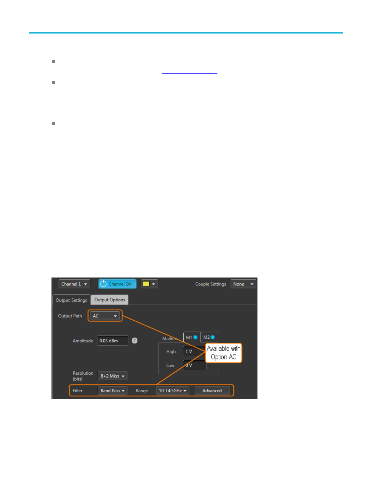
Working with the AWG Channel output path
Direct: Outputs via the Analog + and – differential output connectors, measured in units of volts. This
is the standard signal path. Refer to Direct
AC: Outputs via the single-ended AC connector, measured in units of dBm. The AC path provides
additional amplification and filtering to the A C output connector. The menu c hoice appears if Option
AC is installed and is available only with the AWG70001.
(see page 60) for additional information.
Direct
AC
Refer to AC
DC Amp: This menu choice only appears if a connection to an MDC4500 is sensed via a USB
connection. DC Amp provides greater amplitude range via a connection to an MDC4500 instrument.
The analog + and – differential output connectors must be connected to the input connectors of the
MDC4500 and the Channel Setup controls the outputs of the MDC4500.
Refer t o DC Amplified
Direct is the standard signal output path which uses the analog + and – output connectors. All channel
setup controls operate as explained in the Channel Setup section.
AC is available if Option AC is installed (AWG70001 only). This section describes the differences
between the Direct Output Path and the AC Output Path.
With Option AC installed (AWG70001 only), the Output Path menu includes the AC selection).
(see page 60) for additional information.
(see page 61) for additional information.
The AC Output Path outputs via the single-ended AC connector, measured in units of dBm. The AC path
provides additional amplification and filtering to the AC output connector.
60 AWG70000 Series Arbitrary Waveform Generators Printable Help Document
Page 71

Working with the AWG Channel output path
The following sections discuss the added features when using the AC Output Path.
AC output (see page 62)
Filter and Range (see page 68)
Advanced amplitude adjustment (see page 70)
DC Amplified
This menu choice appears if a connection to an MDC4500 is sensed via a USB connection. A USB
driver must be installed (see page 62) on the AWG.
The DC Amp Output Path is for use when the instrument is directly connected to an MDC4500. The
MDC4500 instrument then becomes the signal output, but is controlled by the AWG. This section
describes the differences between Direct mode and DC Amplified mode.
With the DC Amp Output Path selected, the Channel Setup Amplitude control range changes and an
Offset control is added.
To use the DC Amp Output Path, the following requirements must be met:
A USB connection between the AWG and MDC4500. (The USB driver must be installed.)
The AWG Analog + and – outputs must be connected to the MDC4500 + and – inputs.
Optional – The AWG marker outputs connected to the MDC4500 marker inputs.
Optional – The AWG flag outputs connected to the MDC4500 flag inputs.
The following section discusses the added features when using the DC Amplified Output Path.
DC Amplified output path (see page 63)
Refer to the documentation supplied with the MDC4500 for detailed operating instructions and
specifications about the MDC4500.
AWG70000 Series Arbitrary Waveform Generators Printable Help Document 61
Page 72

Working with the AWG Amplitude
MDC4500 USB installation
A USB connection must be made between the AWG and the MDC4500 instrument.
Install the supplied USB driver on the AWG before making any connections to the MDC4500.
Navigate to:
C:\Program
To install, simply click on the "install.bat" file and follow all prompts through the installation process.
Amplitude
The amplitude sets the analog output level of the differential (+) to (–) outputs. The selected output
mode determines the available range and bandwidth.
The level shown on the Channel Setup tab is the same amplitude shown on the Home tab.
Direct
The level is adjustable from 250 mV
to (–) i
Files\Tektronix\MDC4500 Installer
output path
s 500 mV
p-p
to 1 V
p-p
to 500 mV
p-p
for single-ended output. The differential output (+)
p-p
.
For two channel instruments, the level can be set independently for each channel, unless the Couple
settings has been selected. See Couple channel settings
output path
AC
(see page 65).
If you have an AWG70001 instrument with Option AC installed, you have the option to use the
ingle-ended AC output connector.
s
When set to AC, the output is scaled in dBm but has a higher amplitude output due to the added amplifiers
n the output path.
i
The typical adjustable range is from 18 dBm to –62 dBm, but the range has further limitations based
on filtering selections.
62 AWG70000 Series Arbitrary Waveform Generators Printable Help Document
Page 73

Working with the AWG Amplitude
The amplitude output is calibrated at a single frequency for each filter selection. See the table below
for the ranges and calibration methods.
Filter
selection Amplitude range (typical) Calibration method
None 25 dBm to –70 dBm
Low Pass 25 dBm to –70 dBm
Band Pass
10 to
14.5
GHz
13 to
18 G Hz
xxx
18 dBm to –77 dBm
20 dBm to –90 dBm
Calibrated with a 1 GHz sine w ave.
Calibrated with a 1 GHz sine w ave.
Calibrated with an 11 GHz sine wave.
Calibrated with a 14 GHz sine wave.
NOTE. Adjusting the Amplitude setting automatically causes the instrument to adjust the various inline
uators to attain the chosen amplitude. Readjusting the attenuators will affect the Amplitude setting.
atten
See Advanced amplitude adjustment
(see page 70).
DC Amplified output path
Amplitude sets the Analog output level of the differential (+) to (–) outputs as output from the MDC4500.
The level is adjustable from 31 mV
to (–) is 61 mV
to 2.4 V
p-p
p-p
.
to 1.2 V
p-p
NOTE. This is the output level as seen from the MDC4500, not the AWG70000 instrument.
Offset. The DC Amplified output path also provides the ability to add an offset to the MDC4500 output.
The offset range is –400 mV to 800 mV.
for s ingle-ended output. The differential output (+)
p-p
AWG70000 Series Arbitrary Waveform Generators Printable Help Document 63
Page 74

Working with the AWG Markers
Markers
Each analog output channel is capable of providing up to two markers.
To enable the markers, the bit resolution for the channel must be set to include markers. Each marker uses
one bit (out of the possible 10). See Resolution bits
(see page 65).
The voltage settings of the High and Low levels range between –1.4 V and +1.4 V.
The High
of 1.4 V separation between the settings. A djusting either value forces a change to the other value, if
necessary, to maintain the minimum separation.
and Low settings are inter-dependent, requiring a minimum of 500 mV separation or a maximum
Marker logic state timing
rker outputs can change logic states on any sample point in the waveform. But once the logic state
Ma
changes, it must remain in that state long enough to satisfy the minimum pulse width requirement of 80 ps.
64 AWG70000 Series Arbitrary Waveform Generators Printable Help Document
Page 75

Working with the AWG Resolution (bits)
Resolution (bits)
The bit resolution selection tells the instrument how your waveform was created, either with or without
markers, and sets the channel accordingly.
NOTE. It’s im
Selecting 10+0 Mkr indicates that your waveform is using the entire 10 bits for the waveform.
Selecting 9+1 Mkr indicates that your waveform is using 9 bits for the waveform and the least
significant bit for a single marker.
Selecting 8+2 Mkrs indicates that your waveform is using 8 bits for the waveform and the two least
significant bits for markers.
solution is selectable for each channel.
The re
portant to know if the waveform you intend to assign to a channel is intended to use markers.
Couple channel settings (AWG70002)
Instruments with two channels have the ability to couple the settings of the channels together, allowing you
hange settings to both channels simultaneously from either channel.
to c
AWG70000 Series Arbitrary Waveform Generators Printable Help Document 65
Page 76

Working with the AWG Couple channel settings (AWG70002)
When the Couple settings is set to Pair, the Channel 1 settings overwrite the Channel 2 settings. But
once coupled, you can use either channel to make changes, but the changes to linked settings always
affects both channels.
The following channel settings are coupled together:
66 AWG70000 Series Arbitrary Waveform Generators Printable Help Document
Page 77

Working with the AWG Channel color
Output path
Channel amplitude
Resolution (bits)
Marker High and Low values
Stop state
Wait stat e
NOTE. The c
from the Home tab.
Channel c
Use the c
area on the home tab.
The color is used in the following displays and lights
hannel coupling does not affect the Run Mode coupling. The Run Mode coupling is set
olor
hannel color selection to change the screen color used to display the channel’s plot display
eform plots (on Home tab)
Wav
Marker plots (on Home tab)
Front-panel LED for the channel analog output. (The channel LEDs light when the channel is enabled
for output.) Marker LEDs are always white.
AWG70000 Series Arbitrary Waveform Generators Printable Help Document 67
Page 78

Working with the AWG Filter and Range (Option AC only)
Filter and Range (Option AC only)
With Option AC installed (AWG70001 only), the Filter a nd Range selections become available when the
Output Path is set to AC. They are used to select various cutoff frequencies.
Filter selection Frequency range
None
Low Pass
Band Pass
xxx
NOTE. Filter and Range selections affect the available amplitude output range. See Amplitude (see
page 62).
10MHzto18GHz
10 MHz to 11.5 GHz
Band Pass has two frequency cutoff ranges:
10 GHz to 14.5 GHz
13 GHz to 18 GHz
Output Options
The Output Options tab is accessed from the Channel screen of the Setup tab.
68 AWG70000 Series Arbitrary Waveform Generators Printable Help Document
Page 79

Working with the AWG Output Options
The settings allow you to define the state of the outputs when the channel is enabled but a waveform
is not actively being played out (such as stopped with the play button, waiting for a trigger event, or
assigning a wa
When a channel’s output is off, its analog outputs and marker outputs are electrically disconnected
from the inst
When a channel’s output is enabled, the outputs are electrically connected to the instrument, preparing
to play out a
veform to a channel).
rument (floating).
waveform.
The Streaming tab is only available on the AWG70000B series.
Output value when stopped or waiting
A channel’s analog outputs and marker outputs have various output conditions:
ying – The waveform (and markers if active) are being output.
Pla
Stopped – Waveform playout has been stopped. This can be due to pressing the Play button to stop the
veform playout, the waveform is loading, or a clock change is in progress.
wa
Waiting – The instrument is waiting for a trigger event, or the brief time between when a waveform
as finished loading and playout starts.
h
Sequence End – This is only displayed if Sequencing is available. These are the channel’s Analog
and Marker outputs when the end of a sequence is reached. The instrument continues to output the
indicated values.
AWG70000 Series Arbitrary Waveform Generators Printable Help Document 69
Page 80

Working with the AWG AC Advanced amplitude adjustment (Option AC)
Analog output settings
0 Volt – Output is set to 0 volts.Stopped state
Off – Output is disconnected (floating). There is n o electrical connection between the output
the instrument.
t is set to 0 volts.
– Output is set to the value of the first point of the waveform.
ut is set to 0 volts.
and the instrument.
ut is set to a logic low.
tput is set to a logic high.
int–Outputissettothevalueofthefirst point of the waveform.
tput is set to a logic low.
Waiting state
Sequence En
Marker outputs settings
Waiting state
Sequen
xxx
d state
ce End state
connector and
0Volt–Outpu
First Point
0Volt–Outp
Low – Output is set to a logic low.Stopped state
Off – Output is disconnected (floating). There is n o electrical connection between the output
connector
Low – Outp
High – Ou
First Po
Low – Ou
On a two channel instrument, the stopped and waiting states are set independently of each other unless
you’ve chosen to couple the CH1 and CH2 settings.
AC Ad
The A
From this screen, you can select the Filter Path and Range, which is the same as from the Channel Setup
scr
and the placement of various attenuators.
vanced amplitude adjustment (Option AC)
dvanced button (AC output path) displays the dialog screen that illustrates the output paths available.
een. But from this screen, you can see how the Filter Path and Range selections affect the signal path
70 AWG70000 Series Arbitrary Waveform Generators Printable Help Document
Page 81

Working with the AWG AC Advanced amplitude adjustment (Option AC)
Adjustment Description
DAC This is the signal amplitude of the internal DAC. Changing the DAC level affects the Amplitude
level.
The DAC level affects all Filters and Ranges.
Attenuators
A1
A2
A1 through A3 sets the signal amplitude of the attenuator. Changing an attenuator level affects
the Amplitude level.
Attenuator A1 is active only for the Band Pass Filter Path when the Range is set to 13 - 18 GHz.
Range is 0 to 31 dB in 1 dB increments.
Attenuator A2 is active for all Filter Paths.
Range is 0 to 31 dB in 1 dB increments.
AWG70000 Series Arbitrary Waveform Generators Printable Help Document 71
Page 82

Working with the AWG Clock introduction
Adjustment Description
A3
Amplitude
Attenuator A3 is active for all Filter Paths.
Range is 0 to 75
This is the sig
dB in 5 dB increments.
nal amplitude at the AC output connector.
NOTE. Adjusting the Amplitude setting automatically causes the instrument to adjust the
various inline attenuators to attain the chosen amplitude. Readjusting the attenuators affects
the Amplitud
e setting.
xxx
The amplitude output is calibrated at a single frequency for each filter selection. The following table
lists the ranges and calibration methods.
Filter
selection Amplitude range (typical) Calibration method
None 25 dBm to –70 dBm
Low Pass 25 dBm to –70 dBm
Band Pass
10 to 14.5
GHz
13 to 18
GHz
xxx
18 dBm to –77 dBm
20 dBm to –90 dBm
Clock introduction
The Clock Setup determines the waveform output sample rate and the source used to drive the sample
clock signal. The Reference In signal input is provided to help you synchronize the AWG to your system
g your own reference signal, and the Reference Out signal performs a similar function by making
usin
the AWG's internal frequency source available to other equipment.
The Amplitu
displayed on the Home screen.
de value displayed on the Channel Setup screen is the same Amplitude value
Calibrated with a 1 GHz sine wave.
Calibrated with a 1 GHz sine wave.
Calibrated with an 11 GHz sine wave.
Calibrated with a 14 GHz sine wave.
72 AWG70000 Series Arbitrary Waveform Generators Printable Help Document
Page 83

Working with the AWG Sample Rate
Clock Setup
The Streaming tab is only available on the AWG70000B series.
Sample Rate
The Sample Rate box allows you to set your desired sampling rate. When setting Clock and Reference
Source to Internal or Reference In, External 10 MHz, the instrument automatically creates the sampling
rate (based on a 10 MHz reference signal). When the reference source is set to use an external variable
signal, you can still enter a sampling rate, but its value must be a multiple of the reference signal.
See Clock and Reference Sources
and reference signals.
(see page 73) for more detailed information about sampling rates
Clock and Reference Sources
The Clock and Reference Sources controls let you choose what signal source you want to use as a
frequency reference for the clock signal. The following table describes each of the settings and how
the clock signals are derived.
AWG70000 Series Arbitrary Waveform Generators Printable Help Document 73
Page 84

Working with the AWG Clock and Reference Sources
You can refer to the simplified block diagram to help understand how the choices affect the signal paths.
Internal For general use, this method is usually adequate.
The clock is derived from the instrument’s internal 10 MHz oscillator as the reference s ignal.
is automatically multiplied or divided, based on the selected Sample Rate.
tion if you want to use your own 10 MHz system frequency as a reference.
requency must be between 35 MHz and 250 MHz. The clock is then derived from
Rate based on the r eference in frequency.
Reference in,
10MHz
Reference In, External
Variable
External
The reference
Use this selec
The clock is derived from the 10 MHz signal applied to the Reference In connector. The
reference is automatically multiplied or divided, based on the selected Sample Rate.
Use this selection if you want to use your own system frequency as a reference. This
reference f
the signal applied to the Reference In connector.
When this selection is chosen, use the External Reference Details controls to set or calculate
the Sample
The first i tem to enter is the Reference In frequency. You can enter the value manually or use
the Detect actual freq button to measure the frequency of the applied signal.
After you have the frequency value, you can set the Sample Rate or calculate the Sample
Rate.
With the User enters pull-down list, you have three choices:
Sample Rate: you enter the Sample Rate directly and the Reference In signal is multiplied
or divided as needed to obtain the desired Sample Rate.
Multiplier: Enter a value to multiply the Reference In signal, calculating the Sample Rate.
Divider: Enter a value to divide the Reference In signal, calculating the Sample Rate.
74 AWG70000 Series Arbitrary Waveform Generators Printable Help Document
Page 85

Working with the AWG Clock and Reference Sources
Clock In, Exte
Variable
rnal
Use this selec
connector. The clock signal must be between 6.25 GHz and 12.5 GHz.
tion if you want to provide your own system clock signal applied to the Clock In
When this selection is chosen, use the External Clock Details controls to set or calculate the
Sample Rate ba
The first ite
sed on the clock in frequency.
m to enter is the Clock In frequency. You can enter the value manually or use the
Detect actual freq button to measure the frequency of the applied signal.
After you have the frequency value, you can set the Sample Rate or calculate the Sample
Rate.
With the User enters pull-down list, you have two choices:
Multiplier: Enter a value to multiply the Clock In signal, calculating the Sample Rate.
Divider: Enter a value to divide the Clock In signal, calculating the Sample Rate.
The Adjus
t button allows you to easily calibrate the system clock circuitry. You can run this
at any time. The button turns red when the system detects changes that may impact clock
accuracy, thus requiring an adjustment. A message is also displayed in the Status area at the
bottom o
f the screen, informing you to run the adjustment. When an adjustment is required,
all waveform playout is inhibited.
eduction
Jitter R
Jitter Reduction limits the resolution setting of the Sample Rate w hen using the internal clock
or an external reference.
Clock Out Click to enable the Clock Out signal. The Clock Out signal is based on the Sample Rate and
you synchronize the AWG to your system or DUT, or to synchronize multiple AWGs.
helps
When enabled, the actual clock frequency is reported.
Clock Out is not available when the clock source is set to Clock In, External Variable.
Sync Clock Out Click to enable the Sync Clock Out signal.
ync C lock Out signal is 1/80
The S
th
of the S ample clock and helps you synchronize the AWG
to your system or DUT, or to synchronize multiple AWGs.
xxx
AWG70000 Series Arbitrary Waveform Generators Printable Help Document 75
Page 86

Working with the AWG Clock and Reference Sources
76 AWG70000 Series Arbitrary Waveform Generators Printable Help Document
Page 87

Working with the AWG Clock and sync outputs
Clock and sync outputs
The Clock Out and Sync Clock Out signals are provided to help you synchronize the AWG to your
system or DUT, or to synchronize multiple AWGs. Click the box to enable the outputs of either or both
of these sign
The Clock Out frequency is a r atio based on the Sample Rate setting. The Clock Out readout (in the
clock setti
Clock out is enabled.)
NOTE. The Clock Out frequency will free-run if using an external variable reference and the instrument
loses lock with the signal. Lock can be lost if there is no valid signal applied to the reference input or the
actual signal frequency is different than the value entered in the Reference In freq dialog box.
The Sync Clock Out frequency is derived from Sample Clock through a 1/80 divider.
NOTE. You should disable these outputs when not in use, to reduce the potential for creating unwanted
noise.
al outputs.
ngs panel) provides the actual clock out frequency. (The frequency value is shown only when
Trigger control
Triggers control when a waveform starts to output, after the Play button has been pressed. A trigger event
is necessary when the instrument’s Run Mode is set to a triggered condition.
Trigger control (Run mode
is accessed from the AWG Home tab and is unique for each channel unless the Run modes have been
led together.
coup
Run mode
Triggers (Run mode) control when a waveform is output after the Play button is pressed. Two channel
instruments can use independent Run modes and trigger events.
(see page 77), Trigger Source (see page 78), Trigger coupling (see page 79))
AWG70000 Series Arbitrary Waveform Generators Printable Help Document 77
Page 88

Working with the AWG Trigger control
Run mode
Run mode (accessed from the AWG Home tab) has three sele ctions:
Continuous: Waveform play out starts when the Play button is pressed, without the need for a trigger
event. The waveform continues to repeat until stopped by the user.
Trig gere d: Waveform play out starts when the trigger event occurs. Waveform playout stops after one
complete waveform cycle and remains stopped until the next trigger event. Using a triggered run mode
requires that you select the trigger source. See Trigger source
(see page 78).
Waveform playout cannot be retriggered until the current waveform playout completes an entire cycle.
For two channel instruments, both waveforms must complete a cycle.
Trig ’d Con t.: Waveform playout starts when a trigger event occurs. Once a trigger event occurs,
waveform plays continuously until stopped by the user. (Retriggering is not required nor has any
effect.) Using a triggered run mode requires that you select the trigger source. See Trigger source
page 78).
Trigger source
The trigger source selection only appears when the Run mode is set to a triggered mode (Triggered
or Trig’d Cont.).
Trigger source
(see
The trigger sources available include:
78 AWG70000 Series Arbitrary Waveform Generators Printable Help Document
Page 89

Working with the AWG Trigger input settings
A: The A External Trigger input (rear-panel Trigger Inputs) is used as the source for a trigger event.
The A Force Trigger button is also active.
B: The B External Trigger input (rear-panel Trigger Inputs) is used as the source for a trigger event.
The B Force Trigger button is also active.
Internal: An internally generated trigger signal is used as the trigger source. (The A and B Force
Trigger buttons are not active.)
When using a trigger event to start the waveform playout, you need to define the trigger parameters. Use
the Trigger setup window (located in the Setup tab). See Trigger input settings
(see page 79).
NOTE. For t
trigger source for both channels by coupling the triggers together.
wo channel instruments, each channel can use an independent trigger source or use the same
Trigger coupling
Instruments with two channels have the ability to couple the Run mode and Trigger source together,
allowing you to change settings to both channels simultaneously.
When triggering is initially linked, the Channel 1 settings overwrite the Channel 2 settings. But once
coupled, you can use either channel to make changes.
Trigger input settings
When using a trigger source (Internal or External), you need to define the signal requirements to cause a
trigger event.
Use the Trigger setup screen
AWG70000 Series Arbitrary Waveform Generators Printable Help Document 79
(located in AWG Setup tab).
Page 90

Working with the AWG Trigger input settings
Trigger
The Streaming tab is only available on the AWG70000B series.
Internal Trigger
When the trigger selection is set to Internal (AWG Home screen), the trigger event is generated from
the instrument’s internal clock.
The only setting for the internal trigger is the interval (1 μs to 10 s) at which the trigger signal is generated.
External Trigger
The instrument has two external trigger inputs, A and B. Use the Trigger screen to define the trigger
conditions of each input.
Two channel instruments can use independent trigger sources for each channel.
80 AWG70000 Series Arbitrary Waveform Generators Printable Help Document
Page 91

Working with the AWG Trigger input settings
Item Description
Level
Polarity
Trigger Level sets the threshold that the external trigger input signal must cross for a trigger
event to occur
Select values from –5 V to 5 V.
Trigger Polarity
for a trigger event to occur.
.
sets which slope to use (rising or falling edge) of the external trigger input signal
Impedance
Timing
Trigger pol
r Impedance sets the impedance of the External Trigger inputs to match the impedance
Trigge
of the external source driving the external trigger input signal.
See Rear-panel connectors
Trigger Timing is the trigger timing speed in relation to the frequency of the sampling clock speed.
er timing is selectable between Fast or Slow for when using an external input:
Trigg
Fast (Asynchronous) triggering provides the smallest delay between the trigger event and
starting the waveform playout.
arity
(see page 206).
(Synchronous) triggering slows the trigger clock rate to provide a longer setup time,
Slow
making it easier to align timing events between equipment.
-channel instruments allow this selection f or both the A and B external trigger inputs.
Two
Single-channel instruments allow this selection only for the A external trigger input.
See Trigger timing
gger timing.
tri
xxx
(see page 82) for more information about asynchronous and synchronous
PatternJumpInput
When using Sequencing, the Pattern Jump Input is available as a trigger source.
AWG70000 Series Arbitrary Waveform Generators Printable Help Document 81
Page 92

Working with the AWG Trigger timing
Item Description
Strobe Edge Sets which slope to use ( rising or falling edge) of the pattern jump strobe input signal for a trigger
.
connector.
Jump on strobe
always
xxx
event to occur
A jump based on a pattern requires two things: a strobe edge and an address change at the
Pattern Input
With this checked, a jump always occurs on the strobe edge.
See Creating a Pattern jump (see page 120) for more information.
Trigger timing
The Timing control in the Trigger setup window allows you to select the method most suited to your
application.
Fast (Async) is appropriate for situations like these:
You do not need trigger timing uncertainty better than ± (sample clock period) / 2.
You are using a single trigger event to start AWG output.
You want to minimize trigger uncertainty without synchronizing the AWG to your external system
or device under test (DUT).
Slow (Sync) is useful if your application is like one of these examples:
You need to minimize trigger uncertainty and have the ability to synchronize your trigger signal to
the AWG clocks using one or more of these signal inputs/outputs: Reference In, Reference Out,
Clock Out, or Sync Clock Out.
You are using a trigger signal from your system to the AWG to achieve tight alignment between
the AWG and your external system.
You are synchronizing m ultiple AWGs.
To understand the difference b etween these choices, you need some background on the AWGs internal
clock signals.
82 AWG70000 Series Arbitrary Waveform Generators Printable Help Document
Page 93

Working with the AWG Trigger timing
The internal sample clock signal is what causes the DAC to output waveform samples.
The DAC’s output sample rate is generally a multiple of the sample clock or divided down from
thesampleclock.
Thesampleclockisalwaysavaluebetween6.25GHzand12.5GHz,whilethesampleratecanbe
anywhere from 1.49 kSamples/s to 50 GSamples/s. (The maximum rate varies by instrument model
and options).
The Clock Out signal is the same as the internal sample clock. The Sample Clock is divided by 80 to
produce another timing signal; the Sync Clock Out. The Clock Out and Sync Clock Out signals are
available
The AWG determines when a trigger event has occurred by comparing the trigger input signal’s voltage
level aga
rising and falling edges of the Sample Clock signal for Fast trigger timing, and at the rising edge of the
Sync Clock O ut signal if Slow trigger timing is selected.
The Sample Clock period for Fast (Async) trigger timingcanbeasshortas40ps(for50GS/ssample
rate). If the trigger signal applied to the AWG misses its setup/hold w indow by being either too early
or too late, it will be recognized in the p revious or next cycle, leading to an 80 ps uncertainty for Fast
(Async) mode if you do not use one or more of the clock signals to synchronize your trigger events to
the AWG sample clock.
on rear-panel of the AWG for use in synchronizing the AWG to your external device or system.
inst the trigger level you have set in the Trigger setup window. This comparison occurs at the
Minimum trigger uncertainty is achieved by using a shared clock and/or reference signals to insure that your
trigger event arrives at a consistent location within the selected Trigger Timing clock cycle. The Sample
k period for Slow (Sync) trigger timing is 160 times longer than for the Fast (Async) trigger timing.
Cloc
This extra time makes it easier for your system to assert the trigger event within the setup/hold window.
AWG70000 Series Arbitrary Waveform Generators Printable Help Document 83
Page 94

Working with the AWG Adjust skew
Adjust skew
The Skew adjustments is accessed from the Setup tab.
The Skew and delay adjustments dialog screen is used to:
Adjust the relative timing (skew) between the analog channels (two-channel instruments)
Adjust the relative amplitude and phase (interleave) between the two DACs (single-channel
instruments only)
Adjust the relative timing (delay) of the marker outputs (for each channel)
Adjust the phase of all output signals relative to the system clock
84 AWG70000 Series Arbitrary Waveform Generators Printable Help Document
Page 95

Working with the AWG Adjust skew
Skew adjustments
Channels skew adjust display for two-channel instruments. The Streaming tab is only available
on the AWG7000
0B series.
Marker
skew adjust display for single-channel instruments.
AWG70000 Series Arbitrary Waveform Generators Printable Help Document 85
Page 96

Working with the AWG Adjust skew
Analog channel skew adjustments
With multi-channel instruments, the channel outputs might not always be perfectly aligned, due to many
factors such as differences in cable lengths.
In the Setup menu, select the Skew tab and then the Analog Channels tab to dis play the channel skew. You
can adjust the relative timing of every available channel output within the range of ±100 ps.
NOTE. Adjusting channel skew is best accomplished by viewing the outputs of the channels on an
oscillosco
pe while adjusting.
The Streaming tab is only available on the AWG70000B series.
Interleave adjustment (single channe l models only)
Single channel AWG70000 series instruments interleave the two DACs that the instrument uses to create
the analog output signal. Interleaving the two DACs increases sampling rates and record lengths.
86 AWG70000 Series Arbitrary Waveform Generators Printable Help Document
Page 97

Working with the AWG Adjust skew
The Streaming tab is only available on the AWG70000B series.
The two DACs are clocked 180 ° out of phase from each other. The Interleave adjustments provided allows
you to make small adjustments between the outputs of the two DACs.
Always set your Sample Rate before making interleave adjustments.
Marker delay adjustment
The Marker Delay adjustment is accessed from the Skew tab in the Setup tab.
AWG70000 Series Arbitrary Waveform Generators Printable Help Document 87
Page 98

Working with the AWG Adjust skew
Two markers are available for each channel. Use the Channel pull-down list to select which markers to
adjust.
Youcanaddupto100psdelaytoeachmarker. Themarkerdelayisreferencedtothechannel’sanalog
output.
Signal output phase adjustment
The Phase adjustment for all signal outputs is accessed from the Skew tab in the Setup tab.
hase adjustment allows you to adjust the phase of all signal outputs (except for clocks) to synchronize
The P
output signals between multiple instruments. The phase adjustment is relative to the system clock and is
adjustable from –10000 ° to 10000 ° (or –2 ns to 2 ns). With the right-click menu, you can change the units
for this setting to use either degrees or seconds.
Outputs from the Analog channels, Markers, Flags, and the Sync Out connectors are all affected.
The pha se adjustment is only useful when the instrument is externally triggered.
88 AWG70000 Series Arbitrary Waveform Generators Printable Help Document
Page 99

Working with the AWG Aux Out setup
Aux Out setup
The Aux Out tab allows you to configure the Auxiliary output connectors on the rear panel. (These are
labeled F
lag Outputs on the AWG70000A series.)
NOTE. The Aux Out tab is disabled and Flags are not available if Synchronization is enabled and the
instrument type is set to Master. Refer to Synchronization
The number of available Auxiliary outputs is dependent on the instrument model.
AWG70 0
AWG70002: 1 – 8
Each output can be definedasaFlag(A–D)orasaTimer.
When defined as a flag, y ou need to set the source channel (for two channel instrume nts ). Flags are
used with the sequencer to provide you the ability to add indicators within the sequence to help
identify the state of the sequence. See Sequence flags
The
When defined as a timer, the source channel selection is disabled, and the output is simply a timer
ou
01: 1 – 4
(see page 123) for more details about flags.
flags are output via the Aux Out connectors.
tput. The timer parameters are set in the Timer tab. See Timer setup
(see page 90) for details.
AWG70000 Series Arbitrary Waveform Generators Printable Help Document 89
Page 100

Working with the AWG Timer setup
The Streaming tab is only available on the AWG70000B series.
Timer setup
A timer is available that is output via the Aux Output connectors (located on the rear panel).
The specific Aux Out connector must be configured to output the timer signal. Refer to Aux Out setup
page 89) for information about the Aux Out connectors and settings.
NOTE. The Aux Output connectors are labeled Flag Outputs on the AWG70000A series.
The Streaming tab is only available on the AWG70000B series.
You can start and stop the timer manually using the Stopped/Running button. The Stopped button changes
to Running when the timer is running (manually).
You can also select “Start Timer on Play” to automatically start the timer output each time the instrument
is playing a waveform. (The manual control is disabled when in automatic
mode.)
(see
Use the Period field to set the timing of the signal. Right click in the fieldtosettheperiodinfrequencyor
time.
The period can be set from 1 Hz (1 s) to 100 kHz (10 μs).
90 AWG70000 Series Arbitrary Waveform Generators Printable Help Document
 Loading...