

Page 1

xx
AWG70000A Series and
AWGSYNC01
Rackmount Kit
016-2071-01
ZZZ
Installation
*P071310401*
071-3104-01
x
General Safety Summary
Review the following safety precautions to avoid injury and
prevent damage to this product or any products connected
to it.
To avoid potential hazards, use this product only as
specified.
Only qualified personnel should perform service procedures.
While using this product, you may need to access other
parts of a larger system. Read the safety sections of the
other component manuals for warnings and cautions related
to operating the system.
To Avoid Damage to Equipment and Personal Injury
Do Not Exceed Rackmount Weight Ratings.
rackmount kit only for AWG70000A series instruments and
the AWGSYNC01 Synchronization Hub.
Use Proper Hardware.
rails with other hardware or injury may result. Use only
rails specified for the slides and mounting screws.
Use Care When Installing and Removing Product From
Use two people to install and remove product from
Rack.
rack, one on each side. Avoid pinching fingers and hands
when installing and removing. Do not force the product
into the rails when installing. Gently pull the product out
when removing.
To prevent the instrument from tipping or dropping onto the
installers, two or more people should install this instrument
into the rack cabinet. After completing the installation
procedure, the installers should verify that the instrument
and rack cabinet will not tip forward when the instrument
is in the extended position.
The instrument may need to be extended for access to the
rear panel. Do not leave the instrument extended when
finished accessing the rear panel.
Use Only With Specified Products.
products for which it was not intended. Refer to individual
product manuals for details or contact Tektronix Customer
Service when in doubt.
Do not interchange rack slides or
Do not use rackmount on
Use this
Kit Description
The rackmount kit is a collection of parts that, once installed,
configures a Tektronix AWG70000A Series Arbitrary
Waveform Generator or AWGSYNC01 Synchronization
Hub, for mounting into a standard 19-inch equipment rack.
Installation Instructions
These instructions are for personnel who are familiar
with servicing the product. If you need further details for
disassembling or reassembling the product, refer to the
appropriate product manual. Contact your nearest Tektronix
Service Center or contact Tektronix Factory Service for
installation assistance.
Equipment List
Use the following tools to install the kit hardware:
Phillips #2 and #3 screwdrivers
Torx T20 and T25 screwdrivers
Flat-bladed screwdriver and measuring tape
Installation
Use the following procedure and refer to the illustration to
assemble the rackmount hardware and install the instrument
into the rack. (See Figure 1.)
1.
Remove the two screws (item #10) from the side of
each handle on the front of the instrument.
2.
Install one rack ear over each handle on the instrument,
using the same screws that you removed in step 1.
Item 11 for the AWG70000A Series.
Item 14 for the AWGSYNC01.
3.
Remove the slides from the slide/rail assemblies (item
#3): extend the slide until it locks, and then depress the
spring-lock and pull out the slide.
4.
Install a slide from one of the slide/rail assemblies
on one side of the instrument using three 8–32 x
0.375 screws (item #8). Orient the spring-lock toward
therearoftheinstrument.
5.
Repeat step 4 for the other side of the instrument.
6.
Loosen the screws that attach the brackets to each of
the rail assemblies, and then adjust the rails to barely
cover the screw holes in the front brackets, as shown in
the figure. Tighten the front bracket screws, but leave
the rear bracket screws loose.
7.
Determine where in the equipment rack to mount the
bracket/rail assemblies:
Ensure that there is room for adequate airflow on
each side of the rack.
8.
If you intend to install the instrument immediately
above another instrument in the rack (with no
clearance), first remove the feet from the bottom of
the instrument.
AWG70000A Series: Use a flat-bladed screwdriver
to pry out the 7/16"–deep plug that covers a hidden
fastener, and then use a Torx T20 driver to remove
the bottom feet.
AWGSYNC01: Use a Torx T20 driver to remove
the bottom feet.
9.
Identify the right-side bracket/rail assembly by the
stamped words on the brackets: FRONT on the top-left
(item #5) and REAR (item #4) on the top-right, as
shown in the figure.
10.
Using 4 screws (item #6), install the right-side
bracket/rail assembly in the right-side of the equipment
rack: First attach the front bracket to the front of the
rack, and then adjust and mount the rear bracket to the
rear mount in the equipment rack. Do not tighten the
screws; leave them loose.
11.
Repeat step 10 for the left side of the rack.
12.
With both assemblies mounted in the equipment
rack, tighten the screws that attach the rear brackets
to each of the rail assemblies only; leave the eight
bracket-to-rack screws (item #6) loose.
13.
Roll the ball-bearing sections of each rail assembly to
the front of the rack.
14.
Align the instrument slides to the rails in the equipment
rack, and then slide the instrument into the rack. This
is easier if you have another persontohelpyouliftthe
instrument or guide the slides.
15.
After the instrument reaches the spring locks, depress
them and slide the instrument completely into the rack.
16.
Verify that the instrument slides easily on the rails, and
then tighten the eight screws that secure the front and
rear brackets to the rack.
17.
Attach the instrument to the rack with four 10–32
raised countersunk screws (item #13) and washers
(item #12): two each on the left side and two each
on the right side. Use spacers (item #9) on the upper
screws, behind the rack ears, so that the top of the
instrument mounts securely to the rack. (Spacers are
only required for the AWG70000A series instruments.
18.
Connect the power cord and any other cables required
for your application and verify that the equipment
operates properly.
Page 2
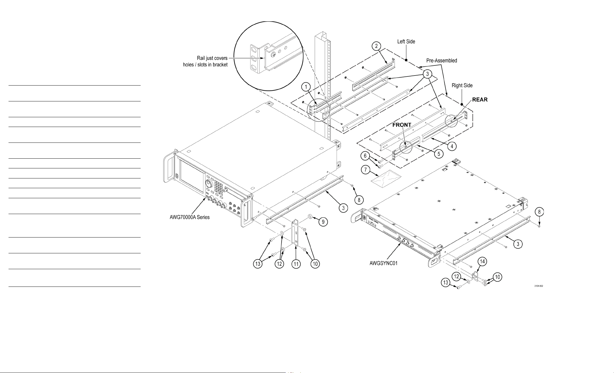
Kit Parts List
The following table lists the parts contained in this kit. Use
the associated figure to identify the parts and to assemble
thekit. (SeeFigure1.)
Table 1: Rackmount kit parts list
Item
no. Qty.
1-1 1 407-5596-xx
1-2 1 407-5597-xx
1-3 2 351-1147-xx
1-4 1 407-5599-xx
1-5 1 407-5598-xx
1-6 8 212-0577-xx
1-7 1
1-8 6 212-0070-xx
1-9 2 129-1748-xx
1-10 4
1-11 2 407-5735-xx
1-12 4 210-0833-xx
1-13 4 212-0591-xx
1-14 2 407-5736-xx
Part
number Name and description
-
-
BRACKET, RACKMOUNT, LEFT
FRONT
BRACKET, RACK MOUNT, LEFT
REAR
ASSEMBLY, SLIDE AND RAIL
BRACKET, RACK MOUNT, RIGHT
REAR
BRACKET, RACK MOUNT, RIGHT
FRONT
SCREW, MACHINE; 10-32 X 0.625
PLASTIC BAG, HARDWARE
SCREW, MACHINE; 8-32 X 0.375
SPACER, RACK EAR
EXISTING HANDLE SCREWS,
PREINSTALLEDONINSTRUMENT
BRACKET, RACK EAR, 3U
(AWG70000A Series Arbitrary
Waveform Generators)
WASHER, RECESSED; 0.42 ID X
0.588 OD
SCREW, RAISED COUNTERSUNK,
10–32 X 0.750
BRACKET, RACK EAR, 1U
(AWGSYNC01 Sync Hub)
Figure 1: Rackmount kit parts
Copyright © Tektronix, Inc. All rights reserved. www.tektronix.com
 Loading...