


User Manual
AWG615
2.7 GS/s Arbitrary Waveform Generator
071-1512-02
This document supports firmware version 4.00 and above.
www.tektronix.com

Copyright © Tektronix. All rights reserved. Licensed software products are owned by Tektronix or its suppliers and
are protected by United States copyright laws and international treaty provisions.
Tektronix products are covered by U.S. and foreign patents, issued and pending. Information in this publication
supercedes that in all previously published material. Specifications and price change privileges reserved.
TEKTRONIX and TEK are registered trademarks of Tektronix, Inc.
Contacting Tektronix
T ektronix, Inc.
14200 SW Karl Braun Drive
P.O. Box 500
Beaverton, OR 97077
USA
For product information, sales, service, and technical support:
In North America, call 1-800-833-9200.
Worldwide, visit www.tektronix.com to find contacts in your area.

WARRANTY 2
Tektronix warrants that this product will be free from defects in materials and workmanship for a period of one (1)
year from the dateof shipment. If any such product proves defective during this warranty period, Tektronix, at its
option, either will repair the defectiveproduct without charge for parts and labor, or will provide a replacement in
exchange for the defective product. Parts, modules andreplacement products used by T ektronix for warranty work may
be new or reconditioned to like new performance. All replaced parts,modules and products become the property of
Tektronix.
In order to obtain service under this warranty, Customer must notify Tektronix of the defect before the expiration of
the warranty period and make suitable arrangements for the performance of service. Customer shall be responsible for
packaging and shipping the defective product to the service center designated by Tektronix, with shipping charges
prepaid. Tektronix shall pay for the return of the product to Customer if the shipment is to a location within the country
in which the Tektronix service center is located. Customer shall be responsible for paying all shipping charges, duties,
taxes, and any other charges for products returned to any other locations.
This warranty shall not apply to any defect, failure or damage caused by improper use or improper or inadequate
maintenance and care. Tektronix shall not be obligated to furnish service under this warranty a) to repair damage
resulting from attempts by personnel other than Tektronix representatives to install, repair or service the product; b) to
repair damage resulting from improper use or connection to incompatible equipment; c) to repair any damage or
malfunction caused by the use of non-Tektronix supplies; or d) to service a product that has been modified or integrated
with other products when the effect of such modification or integration increases the time or difficulty of servicing the
product.
THIS WARRANTY IS GIVEN BY TEKTRONIX IN LIEU OF ANY OTHER WARRANTIES, EXPRESS OR
IMPLIED. TEKTRONIX AND ITS VENDORS DISCLAIM ANY IMPLIED WARRANTIES OF
MERCHANT ABILITY OR FITNESS FOR A P AR TICULAR PURPOSE. TEKTR ONIX' RESPONSIBILITY
TO REPAIR OR REPLACE DEFECTIVE PRODUCTS IS THE SOLE AND EXCLUSIVE REMEDY
PROVIDED TO THE CUSTOMER FOR BREACH OF THIS WARRANTY. TEKTRONIX AND ITS
VENDORS WILL NOT BE LIABLE FOR ANY INDIRECT, SPECIAL, INCIDENTAL, OR
CONSEQUENTIAL DAMAGES IRRESPECTIVE OF WHETHER TEKTRONIX OR THE VENDOR HAS
ADVANCE NOTICE OF THE POSSIBILITY OF SUCH DAMAGES.


Table of Contents
Table of Contents . . . . . . . . . . . . . . . . . . . . . . . . . . . . . . . . . . . . . . . . . . . . . . . . . . . . . . i
General Safety Summary . . . . . . . . . . . . . . . . . . . . . . . . . . . . . . . . . . . . . . . . . . . . . xiii
Environmental Considerations . . . . . . . . . . . . . . . . . . . . . . . . . . . . . . . . . . . . . . . . . xv
Preface . . . . . . . . . . . . . . . . . . . . . . . . . . . . . . . . . . . . . . . . . . . . . . . . . . . . . . . . . . . .xvii
Manual Structure . . . . . . . . . . . . . . . . . . . . . . . . . . . . . . . . . . . . . . . . . . . . . . . . . . . . . xvii
Conventions . . . . . . . . . . . . . . . . . . . . . . . . . . . . . . . . . . . . . . . . . . . . . . . . . . . . . . . . . xix
Related Manuals. . . . . . . . . . . . . . . . . . . . . . . . . . . . . . . . . . . . . . . . . . . . . . . . . . . . . . xix
Getting Started
Getting Started . . . . . . . . . . . . . . . . . . . . . . . . . . . . . . . . . . . . . . . . . . . . . . . . . . . . . 1-1
Product Description . . . . . . . . . . . . . . . . . . . . . . . . . . . . . . . . . . . . . . . . . . . . . . . . . . . 1-1
Incoming Inspection. . . . . . . . . . . . . . . . . . . . . . . . . . . . . . . . . . . . . . . . . . . . . . . . . . . 1-3
Power Cord Options. . . . . . . . . . . . . . . . . . . . . . . . . . . . . . . . . . . . . . . . . . . . . . . . . . . 1-4
Language Options . . . . . . . . . . . . . . . . . . . . . . . . . . . . . . . . . . . . . . . . . . . . . . . . . . . . 1-4
Accessories. . . . . . . . . . . . . . . . . . . . . . . . . . . . . . . . . . . . . . . . . . . . . . . . . . . . . . . . . . 1-5
Options. . . . . . . . . . . . . . . . . . . . . . . . . . . . . . . . . . . . . . . . . . . . . . . . . . . . . . . . . . . . . 1-7
Installation . . . . . . . . . . . . . . . . . . . . . . . . . . . . . . . . . . . . . . . . . . . . . . . . . . . . . . . . . . 1-8
Repackaging for Shipment. . . . . . . . . . . . . . . . . . . . . . . . . . . . . . . . . . . . . . . . . . . . . 1-14
Operating Basics
Operating Basics . . . . . . . . . . . . . . . . . . . . . . . . . . . . . . . . . . . . . . . . . . . . . . . . . . . . 2-1
Controls and Connectors . . . . . . . . . . . . . . . . . . . . . . . . . . . . . . . . . . . . . . . . . . . . . . . 2-1
Menu Operations . . . . . . . . . . . . . . . . . . . . . . . . . . . . . . . . . . . . . . . . . . . . . . . . . . . . . 2-7
Numeric Input . . . . . . . . . . . . . . . . . . . . . . . . . . . . . . . . . . . . . . . . . . . . . . . . . . . . . . 2-11
Text Input. . . . . . . . . . . . . . . . . . . . . . . . . . . . . . . . . . . . . . . . . . . . . . . . . . . . . . . . . . 2-13
Shortcut Controls . . . . . . . . . . . . . . . . . . . . . . . . . . . . . . . . . . . . . . . . . . . . . . . . . . . . 2-14
File Management . . . . . . . . . . . . . . . . . . . . . . . . . . . . . . . . . . . . . . . . . . . . . . . . . . . . 2-16
Quick View. . . . . . . . . . . . . . . . . . . . . . . . . . . . . . . . . . . . . . . . . . . . . . . . . . . . . . . . . 2-23
Editor Overview. . . . . . . . . . . . . . . . . . . . . . . . . . . . . . . . . . . . . . . . . . . . . . . . . . . . . 2-25
Setup Overview . . . . . . . . . . . . . . . . . . . . . . . . . . . . . . . . . . . . . . . . . . . . . . . . . . . . . 2-33
Theory of Operation. . . . . . . . . . . . . . . . . . . . . . . . . . . . . . . . . . . . . . . . . . . . . . . . . . 2-40
Signal Edit Process. . . . . . . . . . . . . . . . . . . . . . . . . . . . . . . . . . . . . . . . . . . . . . . . . . . 2-44
Tutorials . . . . . . . . . . . . . . . . . . . . . . . . . . . . . . . . . . . . . . . . . . . . . . . . . . . . . . . . . . 2-47
Tutorial 1: Instrument Setup . . . . . . . . . . . . . . . . . . . . . . . . . . . . . . . . . . . . . . . . . . . 2-49
Tutorial 2: Loading and Outputting a Sample Waveform . . . . . . . . . . . . . . . . . . . . . 2-51
Tutorial 3: Creating and Editing Standard Function Waveforms. . . . . . . . . . . . . . . . 2-54
Tutorial 4: Editing a Waveform Using Quick Editor . . . . . . . . . . . . . . . . . . . . . . . . . 2-61
Tutorial 5: Using the Equation Editor . . . . . . . . . . . . . . . . . . . . . . . . . . . . . . . . . . . . 2-65
Tutorial 6: Creating and Running Waveform Sequences. . . . . . . . . . . . . . . . . . . . . . 2-68
Reference
Reference . . . . . . . . . . . . . . . . . . . . . . . . . . . . . . . . . . . . . . . . . . . . . . . . . . . . . . . . . . 3-1
Overview . . . . . . . . . . . . . . . . . . . . . . . . . . . . . . . . . . . . . . . . . . . . . . . . . . . . . . . . . . . 3-1
AWG615 Arbitrary Waveform Generator User Manual i

Table of Contents
Menu Structures . . . . . . . . . . . . . . . . . . . . . . . . . . . . . . . . . . . . . . . . . . . . . . . . . . . . . 3-3
Setup Menu Hierarchy . . . . . . . . . . . . . . . . . . . . . . . . . . . . . . . . . . . . . . . . . . . . . . . . . 3-4
EDIT Menu Hierarchy . . . . . . . . . . . . . . . . . . . . . . . . . . . . . . . . . . . . . . . . . . . . . . . . 3-13
APPL Menu Hierarchy . . . . . . . . . . . . . . . . . . . . . . . . . . . . . . . . . . . . . . . . . . . . . . . . 3-26
Utility Menu Hierarchy. . . . . . . . . . . . . . . . . . . . . . . . . . . . . . . . . . . . . . . . . . . . . . . . 3-30
The Setup Menu Screen . . . . . . . . . . . . . . . . . . . . . . . . . . . . . . . . . . . . . . . . . . . . . . 3-33
Setup Menu Screen Elements . . . . . . . . . . . . . . . . . . . . . . . . . . . . . . . . . . . . . . . . . . . 3-33
The Waveform/Sequence Menu . . . . . . . . . . . . . . . . . . . . . . . . . . . . . . . . . . . . . . . . . 3-36
The Vertical Menu. . . . . . . . . . . . . . . . . . . . . . . . . . . . . . . . . . . . . . . . . . . . . . . . . . . . 3-38
The Horizontal Menu . . . . . . . . . . . . . . . . . . . . . . . . . . . . . . . . . . . . . . . . . . . . . . . . . 3-40
The Run Mode Menu . . . . . . . . . . . . . . . . . . . . . . . . . . . . . . . . . . . . . . . . . . . . . . . . . 3-43
The Trigger Menu . . . . . . . . . . . . . . . . . . . . . . . . . . . . . . . . . . . . . . . . . . . . . . . . . . . . 3-45
The Save/Restore Menu . . . . . . . . . . . . . . . . . . . . . . . . . . . . . . . . . . . . . . . . . . . . . . . 3-47
The Extended Operation Menu. . . . . . . . . . . . . . . . . . . . . . . . . . . . . . . . . . . . . . . . . . 3-49
Waveform, Pattern and Sequence Waveform Output . . . . . . . . . . . . . . . . . . . . . . . . . 3-50
The Graphical Waveform Editor . . . . . . . . . . . . . . . . . . . . . . . . . . . . . . . . . . . . . . 3-55
Editor Screen Elements. . . . . . . . . . . . . . . . . . . . . . . . . . . . . . . . . . . . . . . . . . . . . . . . 3-55
The File Menu. . . . . . . . . . . . . . . . . . . . . . . . . . . . . . . . . . . . . . . . . . . . . . . . . . . . . . . 3-58
The Operation Menu . . . . . . . . . . . . . . . . . . . . . . . . . . . . . . . . . . . . . . . . . . . . . . . . . . 3-59
The Tools Menu. . . . . . . . . . . . . . . . . . . . . . . . . . . . . . . . . . . . . . . . . . . . . . . . . . . . . . 3-72
The Zoom/Pan Menu. . . . . . . . . . . . . . . . . . . . . . . . . . . . . . . . . . . . . . . . . . . . . . . . . . 3-81
The Window Menu . . . . . . . . . . . . . . . . . . . . . . . . . . . . . . . . . . . . . . . . . . . . . . . . . . . 3-82
The Settings Menu . . . . . . . . . . . . . . . . . . . . . . . . . . . . . . . . . . . . . . . . . . . . . . . . . . . 3-82
The Pattern Editor . . . . . . . . . . . . . . . . . . . . . . . . . . . . . . . . . . . . . . . . . . . . . . . . . . 3-85
About Waveform and Pattern Files. . . . . . . . . . . . . . . . . . . . . . . . . . . . . . . . . . . . . . . 3-85
Starting the Pattern Editor. . . . . . . . . . . . . . . . . . . . . . . . . . . . . . . . . . . . . . . . . . . . . . 3-86
The File Menu. . . . . . . . . . . . . . . . . . . . . . . . . . . . . . . . . . . . . . . . . . . . . . . . . . . . . . . 3-87
The Operation Menu . . . . . . . . . . . . . . . . . . . . . . . . . . . . . . . . . . . . . . . . . . . . . . . . . . 3-87
The Tools Menu. . . . . . . . . . . . . . . . . . . . . . . . . . . . . . . . . . . . . . . . . . . . . . . . . . . . . . 3-87
The Zoom/Pan Menu. . . . . . . . . . . . . . . . . . . . . . . . . . . . . . . . . . . . . . . . . . . . . . . . . . 3-91
The Window Menu . . . . . . . . . . . . . . . . . . . . . . . . . . . . . . . . . . . . . . . . . . . . . . . . . . . 3-91
The Settings Menu . . . . . . . . . . . . . . . . . . . . . . . . . . . . . . . . . . . . . . . . . . . . . . . . . . . 3-91
The Undo! Command . . . . . . . . . . . . . . . . . . . . . . . . . . . . . . . . . . . . . . . . . . . . . . . . . 3-91
Selecting Data Bits to Edit . . . . . . . . . . . . . . . . . . . . . . . . . . . . . . . . . . . . . . . . . . . . . 3-92
Defining Edit Area . . . . . . . . . . . . . . . . . . . . . . . . . . . . . . . . . . . . . . . . . . . . . . . . . . . 3-93
Creating a Pattern . . . . . . . . . . . . . . . . . . . . . . . . . . . . . . . . . . . . . . . . . . . . . . . . . . . . 3-94
Creating Standard Patterns . . . . . . . . . . . . . . . . . . . . . . . . . . . . . . . . . . . . . . . . . . . . . 3-95
Inserting Data From Files . . . . . . . . . . . . . . . . . . . . . . . . . . . . . . . . . . . . . . . . . . . . . . 3-96
Set Pattern... . . . . . . . . . . . . . . . . . . . . . . . . . . . . . . . . . . . . . . . . . . . . . . . . . . . . . . . . 3-96
Quick Editing . . . . . . . . . . . . . . . . . . . . . . . . . . . . . . . . . . . . . . . . . . . . . . . . . . . . . . 3-99
Screen Display. . . . . . . . . . . . . . . . . . . . . . . . . . . . . . . . . . . . . . . . . . . . . . . . . . . . . . . 3-99
Quick Edit Mode. . . . . . . . . . . . . . . . . . . . . . . . . . . . . . . . . . . . . . . . . . . . . . . . . . . . 3-100
Quick Edit Mechanism . . . . . . . . . . . . . . . . . . . . . . . . . . . . . . . . . . . . . . . . . . . . . . . 3-100
About Smoothing . . . . . . . . . . . . . . . . . . . . . . . . . . . . . . . . . . . . . . . . . . . . . . . . . . . 3-101
Quick Controls . . . . . . . . . . . . . . . . . . . . . . . . . . . . . . . . . . . . . . . . . . . . . . . . . . . . . 3-101
Starting Quick Edit . . . . . . . . . . . . . . . . . . . . . . . . . . . . . . . . . . . . . . . . . . . . . . . . . . 3-102
Exiting Quick Edit. . . . . . . . . . . . . . . . . . . . . . . . . . . . . . . . . . . . . . . . . . . . . . . . . . . 3-103
Setting Parameters. . . . . . . . . . . . . . . . . . . . . . . . . . . . . . . . . . . . . . . . . . . . . . . . . . . 3-103
Moving the Cursor . . . . . . . . . . . . . . . . . . . . . . . . . . . . . . . . . . . . . . . . . . . . . . . . . . 3-104
Renewing Edit Buffer . . . . . . . . . . . . . . . . . . . . . . . . . . . . . . . . . . . . . . . . . . . . . . . . 3-104
ii AWG615 Arbitrary Waveform Generator User Manual

Table of Contents
About Undo . . . . . . . . . . . . . . . . . . . . . . . . . . . . . . . . . . . . . . . . . . . . . . . . . . . . . . . 3-104
The Table Editor . . . . . . . . . . . . . . . . . . . . . . . . . . . . . . . . . . . . . . . . . . . . . . . . . . 3-105
Opening The Table Editor . . . . . . . . . . . . . . . . . . . . . . . . . . . . . . . . . . . . . . . . . . . . 3-105
Editing The Table Data . . . . . . . . . . . . . . . . . . . . . . . . . . . . . . . . . . . . . . . . . . . . . . 3-106
The Equation Editor . . . . . . . . . . . . . . . . . . . . . . . . . . . . . . . . . . . . . . . . . . . . . . . 3-109
Starting the Equation Editor. . . . . . . . . . . . . . . . . . . . . . . . . . . . . . . . . . . . . . . . . . . 3-110
Using the Equation Editor . . . . . . . . . . . . . . . . . . . . . . . . . . . . . . . . . . . . . . . . . . . . 3-111
Entering Keywords and Functions. . . . . . . . . . . . . . . . . . . . . . . . . . . . . . . . . . . . . . 3-114
Compiling Equations . . . . . . . . . . . . . . . . . . . . . . . . . . . . . . . . . . . . . . . . . . . . . . . . 3-115
The Sequence Editor . . . . . . . . . . . . . . . . . . . . . . . . . . . . . . . . . . . . . . . . . . . . . . . 3-117
Starting the Sequence Editor . . . . . . . . . . . . . . . . . . . . . . . . . . . . . . . . . . . . . . . . . . 3-117
Sequence Table Editing . . . . . . . . . . . . . . . . . . . . . . . . . . . . . . . . . . . . . . . . . . . . . . 3-120
Sequence Table Fields . . . . . . . . . . . . . . . . . . . . . . . . . . . . . . . . . . . . . . . . . . . . . . . 3-122
The APPL Menu . . . . . . . . . . . . . . . . . . . . . . . . . . . . . . . . . . . . . . . . . . . . . . . . . . 3-131
Disk Application . . . . . . . . . . . . . . . . . . . . . . . . . . . . . . . . . . . . . . . . . . . . . . . . . . . 3-131
Network Application . . . . . . . . . . . . . . . . . . . . . . . . . . . . . . . . . . . . . . . . . . . . . . . . 3-140
Jitter Composer Application . . . . . . . . . . . . . . . . . . . . . . . . . . . . . . . . . . . . . . . . . . 3-147
The UTILITY Window . . . . . . . . . . . . . . . . . . . . . . . . . . . . . . . . . . . . . . . . . . . . . 3-155
External Keyboards . . . . . . . . . . . . . . . . . . . . . . . . . . . . . . . . . . . . . . . . . . . . . . . . . 3-155
Setting General Purpose Knob Direction. . . . . . . . . . . . . . . . . . . . . . . . . . . . . . . . . 3-156
Formatting a Floppy Disk . . . . . . . . . . . . . . . . . . . . . . . . . . . . . . . . . . . . . . . . . . . . 3-157
Displaying Disk Usage. . . . . . . . . . . . . . . . . . . . . . . . . . . . . . . . . . . . . . . . . . . . . . . 3-157
Screen Display Enable/Disable . . . . . . . . . . . . . . . . . . . . . . . . . . . . . . . . . . . . . . . . 3-158
Focused Color . . . . . . . . . . . . . . . . . . . . . . . . . . . . . . . . . . . . . . . . . . . . . . . . . . . . . 3-158
Displaying Instrument Status. . . . . . . . . . . . . . . . . . . . . . . . . . . . . . . . . . . . . . . . . . 3-158
Internal Clock (Date and Time). . . . . . . . . . . . . . . . . . . . . . . . . . . . . . . . . . . . . . . . 3-159
Resetting the Instrument . . . . . . . . . . . . . . . . . . . . . . . . . . . . . . . . . . . . . . . . . . . . . 3-159
Connecting to a GPIB Network. . . . . . . . . . . . . . . . . . . . . . . . . . . . . . . . . . . . . . . . 3-160
Ethernet Networking . . . . . . . . . . . . . . . . . . . . . . . . . . . . . . . . . . . . . . . . . . . . . . . . 3-162
Hardcopy . . . . . . . . . . . . . . . . . . . . . . . . . . . . . . . . . . . . . . . . . . . . . . . . . . . . . . . . . 3-170
Calibration and Diagnostics. . . . . . . . . . . . . . . . . . . . . . . . . . . . . . . . . . . . . . . . . . . 3-172
Upgrading the System Software . . . . . . . . . . . . . . . . . . . . . . . . . . . . . . . . . . . . . . . 3-179
Capturing Waveforms . . . . . . . . . . . . . . . . . . . . . . . . . . . . . . . . . . . . . . . . . . . . . . 3-181
Possible Instruments . . . . . . . . . . . . . . . . . . . . . . . . . . . . . . . . . . . . . . . . . . . . . . . . 3-181
Basic Concept on Communication for Capturing . . . . . . . . . . . . . . . . . . . . . . . . . . 3-181
Procedures for Capturing Waveforms . . . . . . . . . . . . . . . . . . . . . . . . . . . . . . . . . . . 3-182
About Transferred Files. . . . . . . . . . . . . . . . . . . . . . . . . . . . . . . . . . . . . . . . . . . . . . 3-184
Waveform Programming Language . . . . . . . . . . . . . . . . . . . . . . . . . . . . . . . . . . 3-185
Command Syntax. . . . . . . . . . . . . . . . . . . . . . . . . . . . . . . . . . . . . . . . . . . . . . . . . . . 3-185
User–Defined Variables . . . . . . . . . . . . . . . . . . . . . . . . . . . . . . . . . . . . . . . . . . . . . . 3-186
Waveform Files . . . . . . . . . . . . . . . . . . . . . . . . . . . . . . . . . . . . . . . . . . . . . . . . . . . . 3-187
Command Descriptions . . . . . . . . . . . . . . . . . . . . . . . . . . . . . . . . . . . . . . . . . . . . 3-189
Bpf( ) . . . . . . . . . . . . . . . . . . . . . . . . . . . . . . . . . . . . . . . . . . . . . . . . . . . . . . . . . . . . 3-189
Brf( ) . . . . . . . . . . . . . . . . . . . . . . . . . . . . . . . . . . . . . . . . . . . . . . . . . . . . . . . . . . . . 3-190
Code( ) . . . . . . . . . . . . . . . . . . . . . . . . . . . . . . . . . . . . . . . . . . . . . . . . . . . . . . . . . . . 3-191
Conv( ) . . . . . . . . . . . . . . . . . . . . . . . . . . . . . . . . . . . . . . . . . . . . . . . . . . . . . . . . . . . 3-191
Copy( ) . . . . . . . . . . . . . . . . . . . . . . . . . . . . . . . . . . . . . . . . . . . . . . . . . . . . . . . . . . 3-192
Corr( ) . . . . . . . . . . . . . . . . . . . . . . . . . . . . . . . . . . . . . . . . . . . . . . . . . . . . . . . . . . . 3-192
Data( ) . . . . . . . . . . . . . . . . . . . . . . . . . . . . . . . . . . . . . . . . . . . . . . . . . . . . . . . . . . . 3-193
AWG615 Arbitrary Waveform Generator User Manual iii

Table of Contents
Delete( ) . . . . . . . . . . . . . . . . . . . . . . . . . . . . . . . . . . . . . . . . . . . . . . . . . . . . . . . . . . 3-194
Diff( ) . . . . . . . . . . . . . . . . . . . . . . . . . . . . . . . . . . . . . . . . . . . . . . . . . . . . . . . . . . . .3-194
Expand( ) . . . . . . . . . . . . . . . . . . . . . . . . . . . . . . . . . . . . . . . . . . . . . . . . . . . . . . . . . 3-195
Extract( ) . . . . . . . . . . . . . . . . . . . . . . . . . . . . . . . . . . . . . . . . . . . . . . . . . . . . . . . . . . 3-195
For (Control Statement) . . . . . . . . . . . . . . . . . . . . . . . . . . . . . . . . . . . . . . . . . . . . . . 3-196
Hpf( ) . . . . . . . . . . . . . . . . . . . . . . . . . . . . . . . . . . . . . . . . . . . . . . . . . . . . . . . . . . . . 3-197
If (Control Statement) . . . . . . . . . . . . . . . . . . . . . . . . . . . . . . . . . . . . . . . . . . . . . . . 3-198
Integ( ) . . . . . . . . . . . . . . . . . . . . . . . . . . . . . . . . . . . . . . . . . . . . . . . . . . . . . . . . . . . 3-198
Join( ). . . . . . . . . . . . . . . . . . . . . . . . . . . . . . . . . . . . . . . . . . . . . . . . . . . . . . . . . . . . .3-199
Lpf( ) . . . . . . . . . . . . . . . . . . . . . . . . . . . . . . . . . . . . . . . . . . . . . . . . . . . . . . . . . . . . 3-199
Math Functions . . . . . . . . . . . . . . . . . . . . . . . . . . . . . . . . . . . . . . . . . . . . . . . . . . . . . 3-200
Math Operators . . . . . . . . . . . . . . . . . . . . . . . . . . . . . . . . . . . . . . . . . . . . . . . . . . . . . 3-202
Norm( ) . . . . . . . . . . . . . . . . . . . . . . . . . . . . . . . . . . . . . . . . . . . . . . . . . . . . . . . . . . . 3-203
Pn( ) . . . . . . . . . . . . . . . . . . . . . . . . . . . . . . . . . . . . . . . . . . . . . . . . . . . . . . . . . . . . .3-203
Rename( ) . . . . . . . . . . . . . . . . . . . . . . . . . . . . . . . . . . . . . . . . . . . . . . . . . . . . . . . . . 3-204
Variables (predefined) . . . . . . . . . . . . . . . . . . . . . . . . . . . . . . . . . . . . . . . . . . . . . . . 3-205
Write( ) . . . . . . . . . . . . . . . . . . . . . . . . . . . . . . . . . . . . . . . . . . . . . . . . . . . . . . . . . . . 3-206
Programming Examples . . . . . . . . . . . . . . . . . . . . . . . . . . . . . . . . . . . . . . . . . . . . 3-207
File Conversion . . . . . . . . . . . . . . . . . . . . . . . . . . . . . . . . . . . . . . . . . . . . . . . . . . . . 3-219
Import . . . . . . . . . . . . . . . . . . . . . . . . . . . . . . . . . . . . . . . . . . . . . . . . . . . . . . . . . . . . 3-219
Export . . . . . . . . . . . . . . . . . . . . . . . . . . . . . . . . . . . . . . . . . . . . . . . . . . . . . . . . . . . . 3-221
Convert between Waveform and Pattern. . . . . . . . . . . . . . . . . . . . . . . . . . . . . . . . . . 3-221
Executing File Conversion . . . . . . . . . . . . . . . . . . . . . . . . . . . . . . . . . . . . . . . . . . . . 3-222
File Management . . . . . . . . . . . . . . . . . . . . . . . . . . . . . . . . . . . . . . . . . . . . . . . . . . 3-225
Command Summary . . . . . . . . . . . . . . . . . . . . . . . . . . . . . . . . . . . . . . . . . . . . . . . . . 3-225
Path Name. . . . . . . . . . . . . . . . . . . . . . . . . . . . . . . . . . . . . . . . . . . . . . . . . . . . . . . . . 3-225
File Operations . . . . . . . . . . . . . . . . . . . . . . . . . . . . . . . . . . . . . . . . . . . . . . . . . . . . . 3-226
File Operation in Double Windows. . . . . . . . . . . . . . . . . . . . . . . . . . . . . . . . . . . . . . 3-230
FG Mode . . . . . . . . . . . . . . . . . . . . . . . . . . . . . . . . . . . . . . . . . . . . . . . . . . . . . . . . . 3-233
Change the generator mode. . . . . . . . . . . . . . . . . . . . . . . . . . . . . . . . . . . . . . . . . . . . 3-234
Parameters. . . . . . . . . . . . . . . . . . . . . . . . . . . . . . . . . . . . . . . . . . . . . . . . . . . . . . . . . 3-236
Waveform Mixing Mode . . . . . . . . . . . . . . . . . . . . . . . . . . . . . . . . . . . . . . . . . . . . 3-241
Change the generator mode. . . . . . . . . . . . . . . . . . . . . . . . . . . . . . . . . . . . . . . . . . . . 3-242
File... menu . . . . . . . . . . . . . . . . . . . . . . . . . . . . . . . . . . . . . . . . . . . . . . . . . . . . . . . . 3-243
Waveform Mixing parameters. . . . . . . . . . . . . . . . . . . . . . . . . . . . . . . . . . . . . . . . . . 3-245
Update . . . . . . . . . . . . . . . . . . . . . . . . . . . . . . . . . . . . . . . . . . . . . . . . . . . . . . . . . . . . 3-246
Save/Restore Setup . . . . . . . . . . . . . . . . . . . . . . . . . . . . . . . . . . . . . . . . . . . . . . . . . . 3-247
Operation Flow . . . . . . . . . . . . . . . . . . . . . . . . . . . . . . . . . . . . . . . . . . . . . . . . . . . . . 3-247
Synchronous Operation Mode . . . . . . . . . . . . . . . . . . . . . . . . . . . . . . . . . . . . . . . 3-249
restrictions. . . . . . . . . . . . . . . . . . . . . . . . . . . . . . . . . . . . . . . . . . . . . . . . . . . . . . . . . 3-250
Connecting the cables . . . . . . . . . . . . . . . . . . . . . . . . . . . . . . . . . . . . . . . . . . . . . . . . 3-250
Change the generator mode. . . . . . . . . . . . . . . . . . . . . . . . . . . . . . . . . . . . . . . . . . . . 3-252
Setup screen. . . . . . . . . . . . . . . . . . . . . . . . . . . . . . . . . . . . . . . . . . . . . . . . . . . . . . . . 3-253
Setting a Slave IP address . . . . . . . . . . . . . . . . . . . . . . . . . . . . . . . . . . . . . . . . . . . . . 3-254
Testing the Network Connection. . . . . . . . . . . . . . . . . . . . . . . . . . . . . . . . . . . . . . . . 3-254
Connection with Slave. . . . . . . . . . . . . . . . . . . . . . . . . . . . . . . . . . . . . . . . . . . . . . . . 3-255
Error messages on connection. . . . . . . . . . . . . . . . . . . . . . . . . . . . . . . . . . . . . . . . . . 3-255
Trigger Timing Calibration . . . . . . . . . . . . . . . . . . . . . . . . . . . . . . . . . . . . . . . . . . . . 3-256
Save/Restore Setup . . . . . . . . . . . . . . . . . . . . . . . . . . . . . . . . . . . . . . . . . . . . . . . . . . 3-257
iv AWG615 Arbitrary Waveform Generator User Manual

Appendices
Table of Contents
Operation Flow. . . . . . . . . . . . . . . . . . . . . . . . . . . . . . . . . . . . . . . . . . . . . . . . . . . . . 3-257
Appendix A: Specifications . . . . . . . . . . . . . . . . . . . . . . . . . . . . . . . . . . . . . . . . . . . A-1
Electrical Specification . . . . . . . . . . . . . . . . . . . . . . . . . . . . . . . . . . . . . . . . . . . . . . . . A-2
Certification and Compliances. . . . . . . . . . . . . . . . . . . . . . . . . . . . . . . . . . . . . . . . . . A-24
Appendix B: Performance Verification . . . . . . . . . . . . . . . . . . . . . . . . . . . . . . . . . . B-1
Conventions . . . . . . . . . . . . . . . . . . . . . . . . . . . . . . . . . . . . . . . . . . . . . . . . . . . . . . . . . B-1
Self Tests . . . . . . . . . . . . . . . . . . . . . . . . . . . . . . . . . . . . . . . . . . . . . . . . . . . . . . . . . . .B-2
Performance Tests . . . . . . . . . . . . . . . . . . . . . . . . . . . . . . . . . . . . . . . . . . . . . . . . . . . . B-6
Operating Mode Tests . . . . . . . . . . . . . . . . . . . . . . . . . . . . . . . . . . . . . . . . . . . . . . . . B-12
Amplitude and Offset Accuracy Tests (Normal Out), (except option 02) . . . . . . . . . B-18
Amplitude, Offset Accuracy and
Rise Time Tests (Direct DA Out), (except option 02). . . . . . . . . . . . . . . . . B-22
Amplitude, Offset Accuracy and Rise Time Tests (for option 02) . . . . . . . . . . . . . . B-26
Pulse Response Tests (Normal Out), (except option 02). . . . . . . . . . . . . . . . . . . . . . B-30
Trigger Input Tests . . . . . . . . . . . . . . . . . . . . . . . . . . . . . . . . . . . . . . . . . . . . . . . . . . . B-32
Event Input and Enhanced Mode Tests . . . . . . . . . . . . . . . . . . . . . . . . . . . . . . . . . . . B-36
External Clock Input and VCO Out Output Tests . . . . . . . . . . . . . . . . . . . . . . . . . . . B-45
VCO OUT Output Frequency and 10 MHz Reference Input Tests . . . . . . . . . . . . . . B-47
Marker Output Tests. . . . . . . . . . . . . . . . . . . . . . . . . . . . . . . . . . . . . . . . . . . . . . . . . . B-49
Synchronous Operation Tests. . . . . . . . . . . . . . . . . . . . . . . . . . . . . . . . . . . . . . . . . . . B-51
Appendix C: Inspection and Cleaning . . . . . . . . . . . . . . . . . . . . . . . . . . . . . . . . . . C-1
Appendix D: Sample Waveforms . . . . . . . . . . . . . . . . . . . . . . . . . . . . . . . . . . . . . . . D-1
Waveform File Descriptions. . . . . . . . . . . . . . . . . . . . . . . . . . . . . . . . . . . . . . . . . . . . . D-2
Appendix E: File Transfer Interface Outline . . . . . . . . . . . . . . . . . . . . . . . . . . . . . E-1
Appendix F: Miscellaneous . . . . . . . . . . . . . . . . . . . . . . . . . . . . . . . . . . . . . . . . . . . F-1
Sampling Theorem. . . . . . . . . . . . . . . . . . . . . . . . . . . . . . . . . . . . . . . . . . . . . . . . . . . . F-1
Differentiation . . . . . . . . . . . . . . . . . . . . . . . . . . . . . . . . . . . . . . . . . . . . . . . . . . . . . . . F-1
Integration . . . . . . . . . . . . . . . . . . . . . . . . . . . . . . . . . . . . . . . . . . . . . . . . . . . . . . . . . . F-3
Convolution . . . . . . . . . . . . . . . . . . . . . . . . . . . . . . . . . . . . . . . . . . . . . . . . . . . . . . . . . F-4
Correlation . . . . . . . . . . . . . . . . . . . . . . . . . . . . . . . . . . . . . . . . . . . . . . . . . . . . . . . . . . F-5
Code Conversion . . . . . . . . . . . . . . . . . . . . . . . . . . . . . . . . . . . . . . . . . . . . . . . . . . . . . F-7
Examples . . . . . . . . . . . . . . . . . . . . . . . . . . . . . . . . . . . . . . . . . . . . . . . . . . . . . . . . . . . F-8
Appendix G: Sequence File Text Format . . . . . . . . . . . . . . . . . . . . . . . . . . . . . . . . G-1
Header . . . . . . . . . . . . . . . . . . . . . . . . . . . . . . . . . . . . . . . . . . . . . . . . . . . . . . . . . . . . .G-1
Line Descriptions. . . . . . . . . . . . . . . . . . . . . . . . . . . . . . . . . . . . . . . . . . . . . . . . . . . . . G-1
Jump Settings. . . . . . . . . . . . . . . . . . . . . . . . . . . . . . . . . . . . . . . . . . . . . . . . . . . . . . . . G-3
Examples . . . . . . . . . . . . . . . . . . . . . . . . . . . . . . . . . . . . . . . . . . . . . . . . . . . . . . . . . . . G-4
Index
Index . . . . . . . . . . . . . . . . . . . . . . . . . . . . . . . . . . . . . . . . . . . . . . . . . . . . . . . . . . Index-1
AWG615 Arbitrary Waveform Generator User Manual v

Table of Contents
List of Figures
Figure 1-1: Rear panel power switch, fuse holder, and power connector . . . . . . 1-11
Figure 1-2: Location of the ON/STBY switch . . . . . . . . . . . . . . . . . . . . . . . . . . . . 1-12
Figure 2-1: Front panel controls . . . . . . . . . . . . . . . . . . . . . . . . . . . . . . . . . . . . . . . . 2-2
Figure 2-2: Front panel keypad area . . . . . . . . . . . . . . . . . . . . . . . . . . . . . . . . . . . . 2-3
Figure 2-3: Front panel trigger and output controls . . . . . . . . . . . . . . . . . . . . . . . 2-4
Figure 2-4: Rear panel signal and power connectors . . . . . . . . . . . . . . . . . . . . . . . 2-6
Figure 2-5: Menu buttons, bezel menu buttons, and the CLEAR MENU button 2-7
Figure 2-6: Bottom and side menus . . . . . . . . . . . . . . . . . . . . . . . . . . . . . . . . . . . . . 2-8
Figure 2-7: Pop–up menu example . . . . . . . . . . . . . . . . . . . . . . . . . . . . . . . . . . . . . . 2-9
Figure 2-8: Dialog box example . . . . . . . . . . . . . . . . . . . . . . . . . . . . . . . . . . . . . . . 2-10
Figure 2-9: Knob icon displayed in Status Display area . . . . . . . . . . . . . . . . . . . . 2-11
Figure 2-10: Keypad buttons . . . . . . . . . . . . . . . . . . . . . . . . . . . . . . . . . . . . . . . . . . 2-12
Figure 2-11: Three type of Input text dialog boxes . . . . . . . . . . . . . . . . . . . . . . . . 2-13
Figure 2-12: Shortcut controls . . . . . . . . . . . . . . . . . . . . . . . . . . . . . . . . . . . . . . . . 2-14
Figure 2-13: Files and directories with read only attribute . . . . . . . . . . . . . . . . . 2-20
Figure 2-14: Input Filename dialog box . . . . . . . . . . . . . . . . . . . . . . . . . . . . . . . . 2-20
Figure 2-15: File list window examples in which Quick View is available . . . . . 2-23
Figure 2-16: Viewing a file by Quick View function . . . . . . . . . . . . . . . . . . . . . . . 2-24
Figure 2-17: Main Edit screen . . . . . . . . . . . . . . . . . . . . . . . . . . . . . . . . . . . . . . . . . 2-26
Figure 2-18: Edit top level menu screen with Edit side menu . . . . . . . . . . . . . . . 2-27
Figure 2-19: Editor screen elements . . . . . . . . . . . . . . . . . . . . . . . . . . . . . . . . . . . . 2-28
Figure 2-20: Cursors and edit area . . . . . . . . . . . . . . . . . . . . . . . . . . . . . . . . . . . . . 2-29
Figure 2-21: Multiple editor windows . . . . . . . . . . . . . . . . . . . . . . . . . . . . . . . . . . 2-30
Figure 2-22: Main Setup screen (except option02) . . . . . . . . . . . . . . . . . . . . . . . . 2-33
Figure 2-23: Select File dialog on the Load menu . . . . . . . . . . . . . . . . . . . . . . . . . 2-35
Figure 2-24: Viewing a file in the Setup screen . . . . . . . . . . . . . . . . . . . . . . . . . . . 2-36
Figure 2-25: AWG615 block diagram . . . . . . . . . . . . . . . . . . . . . . . . . . . . . . . . . . 2-42
Figure 2-26: Relationship between memory address control and
waveform memory . . . . . . . . . . . . . . . . . . . . . . . . . . . . . . . . . . . . . . . . . . . . . . . 2-43
Figure 2-27: Cable connection between AWG615 Arbitrary Waveform
Generator and digital storage oscilloscope . . . . . . . . . . . . . . . . . . . . . . . . . . . . 2-48
Figure 2-28: Initial screen . . . . . . . . . . . . . . . . . . . . . . . . . . . . . . . . . . . . . . . . . . . . 2-48
Figure 2-29: System utility screen . . . . . . . . . . . . . . . . . . . . . . . . . . . . . . . . . . . . . . 2-49
Figure 2-30: The Select File list . . . . . . . . . . . . . . . . . . . . . . . . . . . . . . . . . . . . . . . . 2-52
Figure 2-31: Viewing a waveform loaded into memory . . . . . . . . . . . . . . . . . . . . 2-53
Figure 2-32: Waveform editor initial screen . . . . . . . . . . . . . . . . . . . . . . . . . . . . . 2-55
Figure 2-33: The Standard Function dialog box . . . . . . . . . . . . . . . . . . . . . . . . . . 2-56
Figure 2-34: Standard sine wave function created in the Waveform Editor . . . 2-57
Figure 2-35: Waveform created with the multiply operation . . . . . . . . . . . . . . . 2-58
Figure 2-36: File Name Input dialog box . . . . . . . . . . . . . . . . . . . . . . . . . . . . . . . . 2-59
Figure 2-37: Waveform in the waveform editor . . . . . . . . . . . . . . . . . . . . . . . . . . 2-62
Figure 2-38: Waveform edit in quick editor . . . . . . . . . . . . . . . . . . . . . . . . . . . . . 2-63
Figure 2-39: Viewer displaying compiled waveform . . . . . . . . . . . . . . . . . . . . . . 2-67
Figure 2-40: Waveforms created at the same time in three windows . . . . . . . . . 2-70
Figure 2-41: Initial sequence table . . . . . . . . . . . . . . . . . . . . . . . . . . . . . . . . . . . . . 2-71
Figure 2-42: Example of sequence (SUBSEQ.seq) . . . . . . . . . . . . . . . . . . . . . . . . 2-73
vi AWG615 Arbitrary Waveform Generator User Manual

Table of Contents
Figure 2-43: Screen for setting jump mode . . . . . . . . . . . . . . . . . . . . . . . . . . . . . . 2-75
Figure 2-44: Screen for setting event jump . . . . . . . . . . . . . . . . . . . . . . . . . . . . . . 2-76
Figure 2-45: Setup of Goto <N> . . . . . . . . . . . . . . . . . . . . . . . . . . . . . . . . . . . . . . . 2-77
Figure 2-46: Example of sequence (MAINSEQ.seq) . . . . . . . . . . . . . . . . . . . . . . 2-78
Figure 3-1: Overview of AWG615 Arbitrary Waveform Generator process flow 3-1
Figure 3-2: Setup main screen (except option 02) . . . . . . . . . . . . . . . . . . . . . . . . 3-33
Figure 3-3: Run mode and current status . . . . . . . . . . . . . . . . . . . . . . . . . . . . . . . 3-43
Figure 3-4: Trigger slope and trigger level . . . . . . . . . . . . . . . . . . . . . . . . . . . . . . 3-46
Figure 3-5: Waveform output sequence example . . . . . . . . . . . . . . . . . . . . . . . . . 3-50
Figure 3-6: Waveform editor initial screen . . . . . . . . . . . . . . . . . . . . . . . . . . . . . . 3-55
Figure 3-7: Standard Function Waveform dialog box . . . . . . . . . . . . . . . . . . . . . 3-60
Figure 3-8: Register value and tap setting example . . . . . . . . . . . . . . . . . . . . . . . 3-66
Figure 3-9: Shift Register Generator dialog box . . . . . . . . . . . . . . . . . . . . . . . . . 3-67
Figure 3-10: Set Pattern dialog box . . . . . . . . . . . . . . . . . . . . . . . . . . . . . . . . . . . . 3-68
Figure 3-11: Waveform compare operation example . . . . . . . . . . . . . . . . . . . . . 3-75
Figure 3-12: Digital Filter dialog box . . . . . . . . . . . . . . . . . . . . . . . . . . . . . . . . . . 3-78
Figure 3-13: XY View dialog box . . . . . . . . . . . . . . . . . . . . . . . . . . . . . . . . . . . . . . 3-80
Figure 3-14: Settings dialog box . . . . . . . . . . . . . . . . . . . . . . . . . . . . . . . . . . . . . . . 3-83
Figure 3-15: Pattern editor initial screen . . . . . . . . . . . . . . . . . . . . . . . . . . . . . . . 3-86
Figure 3-16: Code Convert dialog box and side menu . . . . . . . . . . . . . . . . . . . . . 3-88
Figure 3-17: Code conversion table . . . . . . . . . . . . . . . . . . . . . . . . . . . . . . . . . . . . 3-89
Figure 3-18: Operating data bits (scope) . . . . . . . . . . . . . . . . . . . . . . . . . . . . . . . . 3-92
Figure 3-19: Area cursors . . . . . . . . . . . . . . . . . . . . . . . . . . . . . . . . . . . . . . . . . . . . 3-94
Figure 3-20: Counter dialog box . . . . . . . . . . . . . . . . . . . . . . . . . . . . . . . . . . . . . . 3-95
Figure 3-21: Set Pattern dialog box . . . . . . . . . . . . . . . . . . . . . . . . . . . . . . . . . . . . 3-96
Figure 3-22: A waveform example under quick editing . . . . . . . . . . . . . . . . . . 3-100
Figure 3-23: Controls for quick editing . . . . . . . . . . . . . . . . . . . . . . . . . . . . . . . . 3-101
Figure 3-24: Table Editor window . . . . . . . . . . . . . . . . . . . . . . . . . . . . . . . . . . . . 3-106
Figure 3-25: Equation editor window . . . . . . . . . . . . . . . . . . . . . . . . . . . . . . . . . 3-110
Figure 3-26: Text selection (example) . . . . . . . . . . . . . . . . . . . . . . . . . . . . . . . . . 3-113
Figure 3-27: File list listing two waveforms created . . . . . . . . . . . . . . . . . . . . . . 3-116
Figure 3-28: Sequence editor initial screen . . . . . . . . . . . . . . . . . . . . . . . . . . . . . 3-117
Figure 3-29: EVENT IN connector . . . . . . . . . . . . . . . . . . . . . . . . . . . . . . . . . . . 3-124
Figure 3-30: Event signal timing and strobe . . . . . . . . . . . . . . . . . . . . . . . . . . . . 3-127
Figure 3-31: Compiling and storing sequences and subsequences . . . . . . . . . . 3-129
Figure 3-32: Outline flow for producing HDD reading test signal . . . . . . . . . . 3-131
Figure 3-33: Disk application initial screen . . . . . . . . . . . . . . . . . . . . . . . . . . . . 3-132
Figure 3-34: Writer Data menu . . . . . . . . . . . . . . . . . . . . . . . . . . . . . . . . . . . . . . 3-132
Figure 3-35: Isolated Pulse menu . . . . . . . . . . . . . . . . . . . . . . . . . . . . . . . . . . . . . 3-133
Figure 3-36: Execution of superpose . . . . . . . . . . . . . . . . . . . . . . . . . . . . . . . . . . 3-133
Figure 3-37: Outline flow for producing network test read signal . . . . . . . . . . 3-140
Figure 3-38: Network application initial screen . . . . . . . . . . . . . . . . . . . . . . . . . 3-140
Figure 3-39: Side menu will change after selecting a standard . . . . . . . . . . . . . 3-141
Figure 3-40: Side menu for selecting the Isolated pulse . . . . . . . . . . . . . . . . . . . 3-142
Figure 3-41: Execution of superposing . . . . . . . . . . . . . . . . . . . . . . . . . . . . . . . . 3-143
Figure 3-42: Outline flow for Jitter waveform creation . . . . . . . . . . . . . . . . . . 3-147
Figure 3-43: Jitter composer application initial screen . . . . . . . . . . . . . . . . . . . 3-148
Figure 3-44: Input Data menu . . . . . . . . . . . . . . . . . . . . . . . . . . . . . . . . . . . . . . . 3-148
Figure 3-45: A pre–defined pattern was selected as an input data . . . . . . . . . . 3-149
Figure 3-46: Jitter profile menu . . . . . . . . . . . . . . . . . . . . . . . . . . . . . . . . . . . . . . 3-149
Figure 3-47: Execution of jitter composer . . . . . . . . . . . . . . . . . . . . . . . . . . . . . . 3-150
AWG615 Arbitrary Waveform Generator User Manual vii

Table of Contents
Figure 3-48: Jitter parameters and jitter waveform . . . . . . . . . . . . . . . . . . . . . . 3-153
Figure 3-49: GPIB setup screen menu . . . . . . . . . . . . . . . . . . . . . . . . . . . . . . . . . 3-161
Figure 3-50: Network setup screen menu . . . . . . . . . . . . . . . . . . . . . . . . . . . . . . 3-163
Figure 3-51: Message box to indicate the establishment of communication . . . 3-165
Figure 3-52: Network Status screen . . . . . . . . . . . . . . . . . . . . . . . . . . . . . . . . . . . 3-165
Figure 3-53: UTILITY screen mounting remote file system . . . . . . . . . . . . . . . 3-166
Figure 3-54: Drive selections in EDIT menu . . . . . . . . . . . . . . . . . . . . . . . . . . . . 3-168
Figure 3-55: Hardcopy setup screen . . . . . . . . . . . . . . . . . . . . . . . . . . . . . . . . . . . 3-171
Figure 3-56: Hardcopy complete message box . . . . . . . . . . . . . . . . . . . . . . . . . . 3-172
Figure 3-57: Calibration and diagnostic screen . . . . . . . . . . . . . . . . . . . . . . . . . 3-173
Figure 3-58: Status message box (except option02) . . . . . . . . . . . . . . . . . . . . . . . 3-174
Figure 3-59: Source instrument selection dialog box . . . . . . . . . . . . . . . . . . . . . 3-182
Figure 3-60: Source instrument selection under Others... . . . . . . . . . . . . . . . . . 3-183
Figure 3-61: Waveforms generated from the Example 1 equation . . . . . . . . . . 3-208
Figure 3-62: Waveform generated by the Example 2 equation . . . . . . . . . . . . . 3-209
Figure 3-63: Waveforms generated by the Example 3 equation . . . . . . . . . . . . 3-210
Figure 3-64: Sequence generated by the Example 3 equation . . . . . . . . . . . . . . 3-211
Figure 3-65: Source waveform and
those generated by the Example 4 equation . . . . . . . . . . . . . . . . . . . . . . . . . . 3-212
Figure 3-66: Noise waveforms after filtering . . . . . . . . . . . . . . . . . . . . . . . . . . . . 3-213
Figure 3-67: Noise waveforms before (upper) and
after (lower) 7–point smoothing . . . . . . . . . . . . . . . . . . . . . . . . . . . . . . . . . . . 3-215
Figure 3-68: Gaussian noise and ramp waveforms . . . . . . . . . . . . . . . . . . . . . . . 3-217
Figure 3-69: Screen and side menu buttons for importing and exporting . . . . 3-222
Figure 3-70: Select the conversion type dialog box . . . . . . . . . . . . . . . . . . . . . . . 3-222
Figure 3-71: Double Windows . . . . . . . . . . . . . . . . . . . . . . . . . . . . . . . . . . . . . . . . 3-230
Figure 3-72: Overwrite confirmation . . . . . . . . . . . . . . . . . . . . . . . . . . . . . . . . . . 3-232
Figure 3-73: Outline flow for producing Function Generator signal . . . . . . . . 3-233
Figure 3-74: FG mode screen (except option 02) . . . . . . . . . . . . . . . . . . . . . . . . . 3-233
Figure 3-75: Change the generator mode (except option 02) . . . . . . . . . . . . . . 3-234
Figure 3-76: Waveform type . . . . . . . . . . . . . . . . . . . . . . . . . . . . . . . . . . . . . . . . 3-235
Figure 3-77: Output parameters (except option 02) . . . . . . . . . . . . . . . . . . . . . . 3-236
Figure 3-78: Marker pattern . . . . . . . . . . . . . . . . . . . . . . . . . . . . . . . . . . . . . . . . . 3-238
Figure 3-79: Pulse sub–side menu (except option 02) . . . . . . . . . . . . . . . . . . . . . 3-240
Figure 3-80: Outline flow for producing Mixed signal . . . . . . . . . . . . . . . . . . . . 3-241
Figure 3-81: Waveform Mixing mode screen . . . . . . . . . . . . . . . . . . . . . . . . . . . 3-241
Figure 3-82: Change the generator mode . . . . . . . . . . . . . . . . . . . . . . . . . . . . . . 3-242
Figure 3-83: Outline flow for producing Synchronous operation . . . . . . . . . . . 3-249
Figure 3-84: Synchronous Operation cable connection . . . . . . . . . . . . . . . . . . . 3-251
Figure 3-85: Change the generator mode . . . . . . . . . . . . . . . . . . . . . . . . . . . . . . 3-252
Figure 3-86: Synchronous Operation mode screen . . . . . . . . . . . . . . . . . . . . . . . 3-253
Figure A-1: Signal Timing . . . . . . . . . . . . . . . . . . . . . . . . . . . . . . . . . . . . . . . . . . . . A-9
Figure A-2: Gated Mode . . . . . . . . . . . . . . . . . . . . . . . . . . . . . . . . . . . . . . . . . . . . A-10
Figure A-3: Enhanced mode . . . . . . . . . . . . . . . . . . . . . . . . . . . . . . . . . . . . . . . . . A-11
Figure A-4: Sequence 2 . . . . . . . . . . . . . . . . . . . . . . . . . . . . . . . . . . . . . . . . . . . . . A-12
Figure A-5: Sequence 3 . . . . . . . . . . . . . . . . . . . . . . . . . . . . . . . . . . . . . . . . . . . . . A-13
Figure A-6: 3-1. Sequence 4 . . . . . . . . . . . . . . . . . . . . . . . . . . . . . . . . . . . . . . . . . . A-14
Figure A-7: The cable connection between units in Synchronous operation . . A-15
Figure A-8: Output Voltage Window ( into 50W to GND ) of MARKER . . . . A-16
Figure A-9: Output part equivalent circuit of MARKE . . . . . . . . . . . . . . . . . . . A-17
Figure A-10: Dimensions . . . . . . . . . . . . . . . . . . . . . . . . . . . . . . . . . . . . . . . . . . . . A-23
viii AWG615 Arbitrary Waveform Generator User Manual

Table of Contents
Figure B-1: Diagnostic menu . . . . . . . . . . . . . . . . . . . . . . . . . . . . . . . . . . . . . . . . . . B-3
Figure B-2: Calibration result message box (except option 02) . . . . . . . . . . . . . . B-5
Figure B-3: EVENT IN connector pins and signals and
ground closure connector . . . . . . . . . . . . . . . . . . . . . . . . . . . . . . . . . . . . . . . . . . B-8
Figure B-4: Loading file; selecting storage drive . . . . . . . . . . . . . . . . . . . . . . . . . . B-9
Figure B-5: Cont mode initial test hookup . . . . . . . . . . . . . . . . . . . . . . . . . . . . . . B-12
Figure B-6: Triggered mode initial test hookup . . . . . . . . . . . . . . . . . . . . . . . . . . B-14
Figure B-7: Relationship between trigger signal and waveform output . . . . . . B-15
Figure B-8: Relationship between gate signal and waveform output . . . . . . . . . B-17
Figure B-9: Amplitude accuracy initial test hookup . . . . . . . . . . . . . . . . . . . . . . B-18
Figure B-10: Direct DA output amplitude accuracy initial test hookup . . . . . . B-22
Figure B-11: Direct DA output pulse rise time initial test hookup . . . . . . . . . . . B-24
Figure B-12: Option02 output amplitude accuracy initial test hookup . . . . . . . B-26
Figure B-13: Optipn02 output pulse rise time initial test hookup . . . . . . . . . . . B-28
Figure B-14: Pulse response initial test hookup . . . . . . . . . . . . . . . . . . . . . . . . . . B-30
Figure B-15: Trigger input initial test hookup . . . . . . . . . . . . . . . . . . . . . . . . . . . B-32
Figure B-16: Trigger signal and waveform output (+5 V check 1) . . . . . . . . . . . B-34
Figure B-17: Trigger signal and waveform output (+5 V check 2) . . . . . . . . . . . B-34
Figure B-18: Trigger signal and waveform output (-5 V check 1) . . . . . . . . . . . B-35
Figure B-19: Trigger signal and waveform output (-5 V check 2) . . . . . . . . . . . B-35
Figure B-20: Event input and enhanced mode initial test hookup . . . . . . . . . . . B-36
Figure B-21: Waveform while all ground disclosure switches are open . . . . . . B-38
Figure B-22: Waveform output when the SW1 is closed . . . . . . . . . . . . . . . . . . . B-38
Figure B-23: Waveform output when SW2 is closed . . . . . . . . . . . . . . . . . . . . . . B-39
Figure B-24: Waveform output when the SW3 is closed . . . . . . . . . . . . . . . . . . . B-39
Figure B-25: Waveform output when SW4 is closed . . . . . . . . . . . . . . . . . . . . . . B-40
Figure B-26: Waveform output when SW6 is closed . . . . . . . . . . . . . . . . . . . . . . B-41
Figure B-27: Waveform output when SW7 is closed . . . . . . . . . . . . . . . . . . . . . . B-41
Figure B-28: Waveform output when SW8 is closed . . . . . . . . . . . . . . . . . . . . . . B-42
Figure B-29: Initial waveform output . . . . . . . . . . . . . . . . . . . . . . . . . . . . . . . . . . B-43
Figure B-30: DC waveform output when the SW5 is closed . . . . . . . . . . . . . . . . B-43
Figure B-31: Trigger input initial test hookup . . . . . . . . . . . . . . . . . . . . . . . . . . . B-45
Figure B-32: VCO OUT outputfrequency and 10 MHz reference input
initial test hookup . . . . . . . . . . . . . . . . . . . . . . . . . . . . . . . . . . . . . . . . . . . . . . . B-47
Figure B-33: Marker output initial test hookup . . . . . . . . . . . . . . . . . . . . . . . . . . B-49
Figure B-34: Synchronous operation test hookup . . . . . . . . . . . . . . . . . . . . . . . . B-51
Figure E-1: File transfer interface outline . . . . . . . . . . . . . . . . . . . . . . . . . . . . . . . E-1
Figure F-1: Equation differentiation . . . . . . . . . . . . . . . . . . . . . . . . . . . . . . . . . . . . F-2
Figure F-2: Equation integration . . . . . . . . . . . . . . . . . . . . . . . . . . . . . . . . . . . . . . . F-3
Figure F-3: Conversion image example . . . . . . . . . . . . . . . . . . . . . . . . . . . . . . . . . . F-7
AWG615 Arbitrary Waveform Generator User Manual ix

List of Tables
List of Tables
Table 1-1: AWG615 waveform editors . . . . . . . . . . . . . . . . . . . . . . . . . . . . . . . . . . 1-2
Table 1-2: Power cord options . . . . . . . . . . . . . . . . . . . . . . . . . . . . . . . . . . . . . . . . . 1-4
Table 1-3: Language options . . . . . . . . . . . . . . . . . . . . . . . . . . . . . . . . . . . . . . . . . . . 1-4
Table 1-4: Standard accessories . . . . . . . . . . . . . . . . . . . . . . . . . . . . . . . . . . . . . . . . 1-5
Table 1-5: Optional accessories . . . . . . . . . . . . . . . . . . . . . . . . . . . . . . . . . . . . . . . . . 1-5
Table 1-6: Fuse and fuse cap part numbers . . . . . . . . . . . . . . . . . . . . . . . . . . . . . . . 1-9
Table 1-7: Power cord identification . . . . . . . . . . . . . . . . . . . . . . . . . . . . . . . . . . . 1-10
Table 2-1: Side menu elements . . . . . . . . . . . . . . . . . . . . . . . . . . . . . . . . . . . . . . . . . 2-9
Table 2-2: Text input button functions . . . . . . . . . . . . . . . . . . . . . . . . . . . . . . . . . 2-14
Table 2-3: Shortcut controls . . . . . . . . . . . . . . . . . . . . . . . . . . . . . . . . . . . . . . . . . . 2-15
Table 2-4: AWG615 Arbitrary Waveform Generator file types . . . . . . . . . . . . . 2-16
Table 2-5: Drive and Directory menus . . . . . . . . . . . . . . . . . . . . . . . . . . . . . . . . . . 2-17
Table 2-6: Waveform record length adjustment messages . . . . . . . . . . . . . . . . . 2-21
Table 2-7: Editors . . . . . . . . . . . . . . . . . . . . . . . . . . . . . . . . . . . . . . . . . . . . . . . . . . . 2-25
Table 2-8: Edit screen bottom menu buttons . . . . . . . . . . . . . . . . . . . . . . . . . . . . . 2-26
Table 2-9: Edit side menu buttons . . . . . . . . . . . . . . . . . . . . . . . . . . . . . . . . . . . . . 2-28
Table 2-10: Setup screen parameter icons . . . . . . . . . . . . . . . . . . . . . . . . . . . . . . . 2-34
Table 2-11: Setup bottom menu buttons . . . . . . . . . . . . . . . . . . . . . . . . . . . . . . . . 2-34
Table 2-12: Setup output parameter operations . . . . . . . . . . . . . . . . . . . . . . . . . . 2-37
Table 2-13: Run modes . . . . . . . . . . . . . . . . . . . . . . . . . . . . . . . . . . . . . . . . . . . . . . 2-40
Table 2-14: Extended operation . . . . . . . . . . . . . . . . . . . . . . . . . . . . . . . . . . . . . . . 2-41
Table 2-15: Editors . . . . . . . . . . . . . . . . . . . . . . . . . . . . . . . . . . . . . . . . . . . . . . . . . . 2-45
Table 2-16: Waveforms to be used in sample sequences . . . . . . . . . . . . . . . . . . . 2-69
Table 2-17: Sequence table contents in SUBSEQ.seq . . . . . . . . . . . . . . . . . . . . . 2-72
Table 2-18: Sequence table contents in MAINSEQ.seq . . . . . . . . . . . . . . . . . . . . 2-74
Table 3-1: AWG615 Arbitrary Waveform Generator main menus . . . . . . . . . . . 3-2
Table 3-2: Waveform parameter icons . . . . . . . . . . . . . . . . . . . . . . . . . . . . . . . . . . 3-34
Table 3-3: Setup bottom menu buttons . . . . . . . . . . . . . . . . . . . . . . . . . . . . . . . . . 3-34
Table 3-4: Status area . . . . . . . . . . . . . . . . . . . . . . . . . . . . . . . . . . . . . . . . . . . . . . . 3-35
Table 3-5: Clock signal output timing . . . . . . . . . . . . . . . . . . . . . . . . . . . . . . . . . . 3-41
Table 3-6: External trigger signal requirements . . . . . . . . . . . . . . . . . . . . . . . . . . 3-45
Table 3-7: Instrument run state and state messages . . . . . . . . . . . . . . . . . . . . . . . 3-52
Table 3-8: Waveform editor screen elements . . . . . . . . . . . . . . . . . . . . . . . . . . . . 3-56
Table 3-9: Waveform editor bottom menu . . . . . . . . . . . . . . . . . . . . . . . . . . . . . . 3-57
Table 3-10: Standard Function Waveform dialog box parameters . . . . . . . . . . . 3-60
Table 3-11: Shift Register Generator dialog box setting parameters . . . . . . . . . 3-67
Table 3-12: Set Pattern dialog box parameters . . . . . . . . . . . . . . . . . . . . . . . . . . . 3-69
Table 3-13: Mathematical function commands . . . . . . . . . . . . . . . . . . . . . . . . . . . 3-72
Table 3-14: Compare dialog box parameters . . . . . . . . . . . . . . . . . . . . . . . . . . . . 3-75
Table 3-15: Convolution dialog box parameters . . . . . . . . . . . . . . . . . . . . . . . . . . 3-76
Table 3-16: Correlation dialog box parameters . . . . . . . . . . . . . . . . . . . . . . . . . . 3-77
Table 3-17: Digital filter dialog box parameters . . . . . . . . . . . . . . . . . . . . . . . . . . 3-78
Table 3-18: Re–sampling dialog box parameters . . . . . . . . . . . . . . . . . . . . . . . . . 3-79
Table 3-19: XY View dialog box parameters . . . . . . . . . . . . . . . . . . . . . . . . . . . . . 3-80
Table 3-20: Zoom/Pan side menu buttons . . . . . . . . . . . . . . . . . . . . . . . . . . . . . . . 3-81
Table 3-21: Setup window parameters . . . . . . . . . . . . . . . . . . . . . . . . . . . . . . . . . . 3-83
x AWG615 Arbitrary Waveform Generator User Manual

List of Tables
Table 3-22: Setup general parameters . . . . . . . . . . . . . . . . . . . . . . . . . . . . . . . . . 3-84
Table 3-23: Pattern editor screen elements . . . . . . . . . . . . . . . . . . . . . . . . . . . . . 3-86
Table 3-24: Pattern editor bottom menu . . . . . . . . . . . . . . . . . . . . . . . . . . . . . . . 3-87
Table 3-25: Code conversion commands . . . . . . . . . . . . . . . . . . . . . . . . . . . . . . . 3-89
Table 3-26: Code conversion parameters . . . . . . . . . . . . . . . . . . . . . . . . . . . . . . . 3-89
Table 3-27: Patterns to be selected in Counter dialog box . . . . . . . . . . . . . . . . . 3-95
Table 3-28: Set Pattern dialog box parameters . . . . . . . . . . . . . . . . . . . . . . . . . . 3-97
Table 3-29: Equation editor screen elements . . . . . . . . . . . . . . . . . . . . . . . . . . . 3-110
Table 3-30: Equation editor bottom menu . . . . . . . . . . . . . . . . . . . . . . . . . . . . . 3-111
Table 3-31: Front–panel Equation editor controls . . . . . . . . . . . . . . . . . . . . . . 3-112
Table 3-32: Control keys from the external keyboard . . . . . . . . . . . . . . . . . . . 3-114
Table 3-33: Sequence table columns . . . . . . . . . . . . . . . . . . . . . . . . . . . . . . . . . . 3-118
Table 3-34: Sequence editor bottom menu . . . . . . . . . . . . . . . . . . . . . . . . . . . . . 3-119
Table 3-35: Pre–defined patterns . . . . . . . . . . . . . . . . . . . . . . . . . . . . . . . . . . . . 3-134
Table 3-36: Code Conversion . . . . . . . . . . . . . . . . . . . . . . . . . . . . . . . . . . . . . . . . 3-134
Table 3-37: Superpose parameters . . . . . . . . . . . . . . . . . . . . . . . . . . . . . . . . . . . 3-138
Table 3-38: Pre–defined patterns . . . . . . . . . . . . . . . . . . . . . . . . . . . . . . . . . . . . 3-144
Table 3-39: Code conversion . . . . . . . . . . . . . . . . . . . . . . . . . . . . . . . . . . . . . . . . 3-144
Table 3-40: Network parameters . . . . . . . . . . . . . . . . . . . . . . . . . . . . . . . . . . . . . 3-145
Table 3-41: Pre–defined patterns . . . . . . . . . . . . . . . . . . . . . . . . . . . . . . . . . . . . 3-151
Table 3-42: Jitter composer parameters . . . . . . . . . . . . . . . . . . . . . . . . . . . . . . . 3-152
Table 3-43: External keyboard edit operations . . . . . . . . . . . . . . . . . . . . . . . . . 3-156
Table 3-44: Available FTP commands . . . . . . . . . . . . . . . . . . . . . . . . . . . . . . . . 3-169
Table 3-45: Diagnostic categories and error codes . . . . . . . . . . . . . . . . . . . . . . 3-176
Table 3-46: BNF symbols and meanings . . . . . . . . . . . . . . . . . . . . . . . . . . . . . . . 3-185
Table 3-47: Programming language math functions . . . . . . . . . . . . . . . . . . . . . 3-200
Table 3-48: Math operators . . . . . . . . . . . . . . . . . . . . . . . . . . . . . . . . . . . . . . . . . 3-202
Table 3-49: Predefined variables . . . . . . . . . . . . . . . . . . . . . . . . . . . . . . . . . . . . . 3-205
Table 3-50: File utility commands . . . . . . . . . . . . . . . . . . . . . . . . . . . . . . . . . . . . 3-225
Table 3-51: Special symbols used for expressing file path . . . . . . . . . . . . . . . . 3-226
Table 3-52: File operation in double windows . . . . . . . . . . . . . . . . . . . . . . . . . . 3-231
Table 3-53: Confirmation selection for copy–all and move–all operations . . . 3-232
Table 3-54: Output frequency and filter cut–off frequency (except option02) 3-237
Table 3-55: Predefined Marker signal . . . . . . . . . . . . . . . . . . . . . . . . . . . . . . . . 3-238
Table 3-56: Output Frequency and Waveform Length . . . . . . . . . . . . . . . . . . . 3-239
Table 3-57: Combination of the file type . . . . . . . . . . . . . . . . . . . . . . . . . . . . . . 3-243
Table 3-58: Difference between AWG mode
and synchronous operation mode . . . . . . . . . . . . . . . . . . . . . . . . . 3-254
Table 3-59: Error/Warning messages . . . . . . . . . . . . . . . . . . . . . . . . . . . . . . . . . 3-255
Table A-1: Run modes . . . . . . . . . . . . . . . . . . . . . . . . . . . . . . . . . . . . . . . . . . . . . . . A-2
Table A-2: Extended Operation . . . . . . . . . . . . . . . . . . . . . . . . . . . . . . . . . . . . . . . . A-2
Table A-3: Arbitrary waveforms . . . . . . . . . . . . . . . . . . . . . . . . . . . . . . . . . . . . . . . A-2
Table A-4: Clock generator . . . . . . . . . . . . . . . . . . . . . . . . . . . . . . . . . . . . . . . . . . . A-3
Table A-5: Internal trigger generator . . . . . . . . . . . . . . . . . . . . . . . . . . . . . . . . . . . A-3
Table A-6: Main output . . . . . . . . . . . . . . . . . . . . . . . . . . . . . . . . . . . . . . . . . . . . . . A-3
Table A-7: Filter (except option 02) . . . . . . . . . . . . . . . . . . . . . . . . . . . . . . . . . . . . A-6
Table A-8: Auxiliary outputs . . . . . . . . . . . . . . . . . . . . . . . . . . . . . . . . . . . . . . . . . . A-6
Table A-9: Marker output Period Jitter . . . . . . . . . . . . . . . . . . . . . . . . . . . . . . . . . A-8
Table A-10: Marker output Cycle to Cycle Jitter . . . . . . . . . . . . . . . . . . . . . . . . . A-8
Table A-11: VCO output Period Jitter . . . . . . . . . . . . . . . . . . . . . . . . . . . . . . . . . . A-8
Table A-12: VCO output Cycle to Cycle Jitter . . . . . . . . . . . . . . . . . . . . . . . . . . . A-8
AWG615 Arbitrary Waveform Generator User Manual xi

List of Tables
Table A-13: Auxiliary inputs . . . . . . . . . . . . . . . . . . . . . . . . . . . . . . . . . . . . . . . . . . A-9
Table A-14: Event Input . . . . . . . . . . . . . . . . . . . . . . . . . . . . . . . . . . . . . . . . . . . . A-19
Table A-15: 10 MHz reference clock input . . . . . . . . . . . . . . . . . . . . . . . . . . . . . A-19
Table A-16: External clock input . . . . . . . . . . . . . . . . . . . . . . . . . . . . . . . . . . . . . A-19
Table A-17: C input . . . . . . . . . . . . . . . . . . . . . . . . . . . . . . . . . . . . . . . . . . . . . . . . A-20
Table A-18: T input . . . . . . . . . . . . . . . . . . . . . . . . . . . . . . . . . . . . . . . . . . . . . . . . A-20
Table A-19: Function Generator (FG) . . . . . . . . . . . . . . . . . . . . . . . . . . . . . . . . . A-21
Table A-20: Display . . . . . . . . . . . . . . . . . . . . . . . . . . . . . . . . . . . . . . . . . . . . . . . . A-22
Table A-21: AC line power . . . . . . . . . . . . . . . . . . . . . . . . . . . . . . . . . . . . . . . . . . A-22
Table A-22: Timer . . . . . . . . . . . . . . . . . . . . . . . . . . . . . . . . . . . . . . . . . . . . . . . . . A-22
Table A-23: Interface connectors . . . . . . . . . . . . . . . . . . . . . . . . . . . . . . . . . . . . . A-22
Table A-24: Installation requirement . . . . . . . . . . . . . . . . . . . . . . . . . . . . . . . . . . A-23
Table A-25: Maintenance requirement . . . . . . . . . . . . . . . . . . . . . . . . . . . . . . . . A-23
Table A-26: Environmental . . . . . . . . . . . . . . . . . . . . . . . . . . . . . . . . . . . . . . . . . . A-23
Table A-27: Mechanical . . . . . . . . . . . . . . . . . . . . . . . . . . . . . . . . . . . . . . . . . . . . . A-24
Table A-28: Certifications and compliances . . . . . . . . . . . . . . . . . . . . . . . . . . . . A-25
Table A-29: Installation category and Pollution degree Descriptions . . . . . . . . A-26
Table B-1: Performance test items . . . . . . . . . . . . . . . . . . . . . . . . . . . . . . . . . . . . . B-6
Table B-2: Test equipment . . . . . . . . . . . . . . . . . . . . . . . . . . . . . . . . . . . . . . . . . . . B-7
Table B-3: Waveforms and sequences in performance check disk . . . . . . . . . . B-10
Table C-1: External inspection check list . . . . . . . . . . . . . . . . . . . . . . . . . . . . . . . C-1
Table D-1: Waveform and equation files in the sample disk . . . . . . . . . . . . . . . . D-1
Table D-2: Gaussian pulse . . . . . . . . . . . . . . . . . . . . . . . . . . . . . . . . . . . . . . . . . . . . D-2
Table D-3: Lorentz pulse . . . . . . . . . . . . . . . . . . . . . . . . . . . . . . . . . . . . . . . . . . . . . D-3
Table D-4: Sampling function SIN(X)/X pulse . . . . . . . . . . . . . . . . . . . . . . . . . . . D-3
Table D-5: Squared sine pulse . . . . . . . . . . . . . . . . . . . . . . . . . . . . . . . . . . . . . . . . . D-4
Table D-6: Double exponential pulse . . . . . . . . . . . . . . . . . . . . . . . . . . . . . . . . . . . D-4
Table D-7: Nyquist pulse . . . . . . . . . . . . . . . . . . . . . . . . . . . . . . . . . . . . . . . . . . . . . D-5
Table D-8: Linear frequency sweep . . . . . . . . . . . . . . . . . . . . . . . . . . . . . . . . . . . . D-6
Table D-9: Log frequency sweep . . . . . . . . . . . . . . . . . . . . . . . . . . . . . . . . . . . . . . . D-6
Table D-10: Amplitude modulation . . . . . . . . . . . . . . . . . . . . . . . . . . . . . . . . . . . . D-7
Table D-11: Frequency modulation . . . . . . . . . . . . . . . . . . . . . . . . . . . . . . . . . . . . D-7
Table D-12: Pulse width modulation . . . . . . . . . . . . . . . . . . . . . . . . . . . . . . . . . . . D-8
Table D-13: Pseudo–random pulse . . . . . . . . . . . . . . . . . . . . . . . . . . . . . . . . . . . . . D-8
Table D-14: Waveform for magnetic disk signal . . . . . . . . . . . . . . . . . . . . . . . . . . D-8
Table D-15: Isolated pulse for disk application . . . . . . . . . . . . . . . . . . . . . . . . . . . D-9
Table D-16: Isolated pulse for disk application . . . . . . . . . . . . . . . . . . . . . . . . . . . D-9
Table D-17: Isolated pulse for disk application . . . . . . . . . . . . . . . . . . . . . . . . . . D-10
Table D-18: Isolated pulse for network application . . . . . . . . . . . . . . . . . . . . . . D-10
Table D-19: Isolated pulse for network application . . . . . . . . . . . . . . . . . . . . . . D-11
Table D-20: Isolated pulse for network application . . . . . . . . . . . . . . . . . . . . . . D-11
Table D-21: Isolated pulse for network application . . . . . . . . . . . . . . . . . . . . . . D-11
Table D-22: Isolated pulse for network application . . . . . . . . . . . . . . . . . . . . . . D-12
Table D-23: Isolated pulse for network application . . . . . . . . . . . . . . . . . . . . . . D-12
xii AW G615 Arbitrary Waveform Generator User Manual

General Safety Summary
Review the follo wing safety precautions to a void injury and prev ent damage to this
product or any products connected to it. T o a void potential hazards, use this product
only as specified.
Only qualified personnel should perform service procedures.
To Avoid Fire or Personal
Injury
Use Proper Power Cord. Use only the power cord specified for this product and
certified for the country of use.
Ground the Product. This p roduct is grounded thro ugh the grounding con ductor of
the power cord. To avoid electric shock, the grounding conductor must be
connected to earth ground. Before making connections to the input or output
terminals of the product, ensure that the product is properly grounded.
Observe All Terminal Ratings. To avoid fire or shock hazard, observe all ratings and
markings on the product. Consult the product manual for further ratings
information before making connections to the product.
The common terminal is at ground potential. Do not connect the common terminal
to elevated voltages.
Do not apply a potential to any terminal, including the common terminal, that
exceeds the maximum rating of that terminal.
Do Not Operate Without Covers. Do not operate this product with covers or panels
removed.
Use Proper Fuse. Use only the fuse type and rating specified for this product.
Avoid Exposed Circuitry. Do not touch exposed connections and components when
power is present.
Do Not Operate With Suspected Failures. If you suspect there is damage to this
product, have it inspected by qualified service personnel.
Do Not Operate in Wet/Damp Conditions.
Do Not Operate in an Explosive Atmosphere.
Keep Product Surfaces Clean and Dry.
Provide Proper Ventilation. Refer to the manual’s installation instructions for details
on installing the product so it has proper ventilation.
AWG615 Arbitrary Waveform Generator User Manual xiii

General Safety Summary
Symbols and Terms
Terms in this Manual. These terms may appear in this manual:
WARNING. W arning statements identify conditions or practices that could r esult in
injury or loss of life.
CAUTION. Caution statements identify conditions or pr actices that could result in
damage to this product or other property.
Terms on the Product. These terms may appear on the product:
DANGER indicates an injury hazard immediately accessible as you read the
marking.
WARNING indicates an injury hazard not immediately accessible as you read the
marking.
CAUTION indicates a hazard to property including the product.
Symbols on the Product. The following symbols may appear on the product:
WARNING
High Voltage
Protective Ground
(Earth) Terminal
CAUTION
Refer to Manual
Double
Insulated
xiv AWG615 Arbitrary Waveform Generator User Manual

Environmental Considerations
This section provides information about the environmental impact of the product.
Product End-of-Life
Handling
Restriction of Hazardous
Substances
Observe the following guidelines when recycling an instrument or component:
Equipment Recycling. Production of this equipment requi red the extraction and use
of natural resources. The equipment may contain substances that could be harmful
to the environment or human health if improperly handled at the product's end of
life. In order to avoid release of such substances into the environment and to reduce
the use of natural resources, we encourage you to recycle this product in an
appropriate system that will ensure that most of the materials are reused or recycled
appropriately.
The symbol shown to the left indicates that this product complies
with the European Union's requirements according to Directive
2002/96/EC on waste electrical and electronic equipment (WEEE).
For information about recycling options, check the Support/Service
section of the Tektronix Web site (www.tektronix.com).
Mercury Notification. This product uses an LCD backlight lamp that contains
mercury. Disposal may be regulated due to environmental considerations. Please
contact your local authorities or, within the United States, the Electronics
Industries Alliance (www.eiae.org) for disposal or recycling information.
This product has been classified as Monitoring and Control equipment, and is
outside the scope of the 2002/95/EC RoHS Directive. This product is known to
contain lead, cadmium, mercury, and hexavalent chromium.
AWG615 Arbitrary Waveform Generator User Manual xv

Environmental Considerations
xvi AWG615 Arbitrary Waveform Generator User Manual

Preface
Manual Structure
This manual provides user information for the AWG615 Arbitrary Waveform
Generator.
The AWG615 Arbitrary Wav eform Generator User Manual cont ains the follo wing
sections:
The Getting Started section covers initial instrument inspection, available options
and accessories, instrument installation procedures, and power on and off
procedures. In particular, the installation section covers the procedures required
prior to turning on the unit and areas of the instrument that require special care or
caution.
The Oper ating Basics section describes instrument controls and menus, introduces
instrument–specific terminology, provides an overview of the instrument internal
structure, operating principles, basic operating procedures, and numeric input
methods. This section also provides basic signal editing examples.
The Reference section describes the functions and menu operations.
The Appendices provide product specifications, performance verification
procedures, sample waveforms, file transfer, outline sequence file text format,
inspection and cleaning instructions.
AWG615 Arbitrary Waveform Generator User Manual xvii

Preface
Conventions
This manual uses the following conventions:
Front–panel button and control labels are printed in the manual in upper case
text. For example, SETUP, SHIFT, APPL. If it is part of a procedure, the
button or control label is printed in boldface. For example, Select SETUP.
Menu and on–screen form titles are printed in the manual in the same case
(initial capitals or all uppercase) as they appear on the instrument screen (for
example, Offset Vertical). If it is part of a procedure, the menu title is shown
in boldface (for example, ‘Select the Vertical menu’).
A list of buttons, controls, and/or menu items separated by an arrow symbol
(!) indicates the order in which to perform the listed tasks. For example:
Select SETUP (front)!Vertical (bottom)!Offset (side)!10MHz (knob).
The text in parenthesis indicates the type of button, knob, menu , or form item
to select or modify, as described in the following table.
Type Description
front Push the indicated front–panel button
bottom Push the indicated bottom–menu button
side Push the indicated side–menu button
knob Turn the indicated front–panel control knob (usually the general purpose knob)
pop–up Make selections or change values in the indicated pop–up menu
dialog Make selections or change values in the indicated dialog box
screen Make selections or change values on the indicated instrument screen
xviii AWG615 Arbitrary Waveform Generator User Manual

Related Manuals
Preface
Following are additional manuals that are available for the AWG615 Arbitrary
Waveform Generator:
The AWG615 Arbitrary Waveform Generator Programmer Manual provides
complete information on programming and remote control of the instrument
through the GPIB/Ethernet interfaces. This manual is a standard accessory.
The AWG615 Arbitr ary W aveform Generator Service Manual describes how to
maintain and service the AWG615 Arbitrary Waveform Generator and
provides a complete module–level description of the instrument operation.
This manual is an optional accessory.
AWG615 Arbitrary Waveform Generator User Manual xix

Preface
xx AWG615 Arbitrary Waveform Generator User Manual

Getting Started


Getting Started
Product Description
This section provides the following information:
Description and features of the AWG615 Arbitrary Waveform Generator
Initial inspection procedure
Standard and optional accessories listings
Installation procedures
Power on and off procedures
Repackaging procedure for shipment
The AWG615 Arbitrary Waveform Generator is a waveform generator that can
generate simple and arbitrary waveforms and generates one–channel differential
output arbitrary waveforms and function generator waveforms.
The AWG615 Arbitrary Waveform Generator allows you to create sine, triangle,
square, ramp, and complex waves, as well as direct current and noises signals. It
allows you to set waveform attributes, such as frequency, amplitude, and offset.
Main Features
This instrument contains a hard disk drive, a 3.5–inch floppy disk drive, and
Ethernet interface for storing and recalling waveform data and instrument settings.
You can remotely control the instrument by sending commands through both the
GPIB and 100/10BASE–T interfaces, as well as transfer waveform data directly
from a digital storage oscilloscope to the AWG615 Arbitrary Wav eform Generator
using the GPIB interface. This enables you to use the instrument in combination
with other measurement equipment and a computer.
The AWG615 Arbitrary Waveform Generator contains the following main
features:
2.7 GS/s Sampling Rate8–bit DA converter
32.4 M–word waveform memory (62.8 M optional)
Two arbitrary marker outputs
AWG615 Arbitrary Waveform Generator User Manual 1-1

Getting Started
Five waveform editors (see Table 1-1)
Table 1-1: AWG615 waveform editors
Editor Description
Waveform Creates analog waveform data in graphic or tabular form.
Pattern Creates analog waveform data in timing and table form.
Sequence Creates sequences of waveforms by combining the waveform files
created with the Waveform and/or Pattern Editors.
Text Edits plain ASCII–format waveform files. For example, you can use
the Text editor to edit ASCII–format waveform files that are read from
an external device.
Equation Creates files with equations and compiles them into waveform files.
FG mode to generate a standard functional waveform easily
Waveform Mixing mode to generate a mixing two-signals digitally.
Synchronous operation mode to generate 2 channel signals by tw o AWG615s.
Additional Features
The AWG615 Arbitrary Waveform Generator provides the following additional
features:
An Ethernet port for using the NFS (Network File System) and/or FTP link.
Refer to Ethernet Networking on page 3-162 for information.
A GPIB interface that can be used for remotely controlling the AWG615
Arbitrary W aveform Generator and for transferring the w aveform data from the
external oscilloscopes.
Refer to Connecting to a GPIB Network on page 3-160 for information on
setting the GPIB parameters.
Refer to the AAWG615 Arbitrary Waveform Generator Programmer Manual
for information on the remote control commands.
Refer to Capturing Waveforms on page 3-181 for information about
transferring waveforms from the external oscilloscopes to the AWG615
Arbitrary Waveform Generator.
A port on the rear panel for connecting a 101– or 106– type keyboard to the
A WG615 Arbitrary Waveform Generator . You can input values or text with the
keyboard instead of using the numeric keypad on the front–panel. Refer to
External Ke yboards on page 3-155 for information.
An adjustment of focused color. Refer to Focused Color on page 3-158 for
information. This setup procedure is also described in Tutorial 1: Instrument
Setup on page 2-49.
1-2 AWG615 Arbitrary Waveform Generator User Manual

Incoming Inspection
Getting Started
Inspect the A WG615 Arbitrary Waveform Generator carton for external damage. If
the carton is damaged, notify the carrier.
Remove the AWG615 Arbitrary Waveform Generator from its carton and check
that the instrument has not been damaged in transit. Verify that the carton contains
the basic instruments and its standard accessories. Refer to Standard Accessories
on page 1-5.
This instrument was thoroughly inspected for mechanical and electrical defects
before shipment. It should be free of dents or scratches. T o conf irm this, inspect the
instrument for physical damage that occurred in transit, and test the instrument
functionality by following the Tutorials beginning on page 2-47. You can also
verify the performance of the instrument by following the procedures in Appendix
Appendix B:Performance Verification beginning on page B-1. If a discrepancy is
found, contact your local Tektronix Field Office or representative.
NOTE. Save the shipping carton and packaging materials for repacka ging in case
shipment becomes necessary.
AWG615 Arbitrary Waveform Generator User Manual 1-3

Getting Started
Power Cord Options
T a ble 1-2 lists the po wer cords a v ailable with the AWG615 Arbitrary W a v eform
Generator.
Table 1-2: Power cord options
Option Description Tektronix part number
Standard US Power Cord, 115 V 161–0104–00
A1 Europe, 220 V 161–0104–06
A2 United Kingdom, 240 V 161–0104–07
A3 Australia, 240 V 161–0104–05
A5 Switzerland, 220 V 161–0167–00
A6 Japan, 100 V 161–A005–00
A10 China, 240 V 161–0306–00
A99 No power cord ----------
Language Options
The following two language options are provided for the AWG615 Arbitrary
Waveform Generator.
Table 1-3: Language options
Option Description Part number
L0 English manuals
User manual 071–1512–xx
Programmer manual 071–1513–xx
Registration card 001–1121–01
L5 Japanese manuals
User manual 071–1514–xx
Programmer manual 071–1515–xx
Registration card 000–A058–00
1-4 AWG615 Arbitrary Waveform Generator User Manual

Accessories
Getting Started
Standard Accessories
Optional Accessories
The AWG615 Arbitrary Waveform Generator includes the standard accessories
listed in Table 1-4:
Table 1-4: Standard accessories
Accessory Part number
User Manual
Sample waveform floppy disk, 3.5 inch for 063–3779–xx
Sample program floppy disk, 3.5 inch 062–A258–xx
Performance check/adjustment floppy disk, 3.5 inch 063–3780–xx
ArbExpress Software 063–3763–xx
ArbExpress Software Instructions 061–4288–xx
SMA 50 Ω terminator, Male (2 installed on the instrument) 015–1022–01
Power Cord (except A99) (see Table 1-2)
See Table 1-3 for part
numberProgrammer Manual
The following optional accessories, listed in Table 1-5, are recommended for use
with the instrument:
Table 1-5: Optional accessories
Accessory Part number
Service Manual 071–1516–xx
Front cover 200–3696–01
Rack Mount Kit (for field conversion) 020–2556–00
GPIB cable 012–0991–00
BNC cable, 50 Ω,
BNC cable, 50 Ω, 2.5 m (8.2 ft), double–shield 012–1256–00
BNC terminator, 50 Ω 011–0049–02
BNC power divider, 50 Ω, DC to 300 MHz, VSWR: 1.2 max. 015–0660–00
SMA cable, 50 Ω, 0.5 m, (1.64 ft), Male–Male 174–1427–00
SMA cable, 50 Ω, 1.0 m, (3.28 ft), Male–Male 174–1341–00
SMA cable, 50 Ω, 1.5 m, (4.92 ft), Male–Male 174–1428–00
SMA precision delay cable, 1 ns, Male–Male 015–0562–00
SMA precision delay cable, 2 ns, Male–Male 015–0560–00
SMA precision delay cable, 5 ns, Male–Male 015–0561–00
SMA T–connector, Male–Female & Female 015–1016–00
SMA Terminator, Male 015–1022–00
0.6 m (2 ft) 012–1342–00
AWG615 Arbitrary Waveform Generator User Manual 1-5

Getting Started
Table 1-5: Optional accessories (cont.)
Accessory Part number
SMA 50 Ω divider, Male 015–1014–00
SMA–BNC adapter, Male–Female 015–0554–00
SMA–BNC adapter, Female–Male 015–0572–00
SMA adapter kit 020–1693–00
BNC low pass filter, 400 MHz 015–0659–00
BNC low pass filter, 200 MHz 015–0658–00
BNC low pass filter, 100 MHz 015–0657–00
AC Current Probe CT-1 CT1
AC Current Probe CT-2 CT2
AC Current Probe CT-3 CT6
Cart K475
1-6 AWG615 Arbitrary Waveform Generator User Manual

Options
Getting Started
This subsection describes the following options available with the AWG615
Arbitrary Waveform Generator:
Option 01 (64.8 M Words memory)
Option 02 (High Bandwidth output)
Option 1R (Rack mounting)
Option 10 (Flash disk, 256 MB)
Option D1 (Test result report, English)
Each of these options is discussed in detail in the following paragraphs.
Option 01 (64.8 MB Words
Memory)
Option 02 (High
Bandwidth Output)
Option 1R (Rack Mounting)
Option 10 (Flash Disk)
Increase memory length up to 64.8 M word (64,800,000 points).
Expand output bandwidth
The product which has option 02 doesn’t have offset and lowpass filter function,
also, main output amplitude of 20mVp-p to 2Vp-p is changed to 500mVp-p to
1Vp-p into a 50 Ohm load.
AWG615 Arbitrary Waveform Generator comes configured for installation in a
19–inch wide instrument rack. For later field conversions, order Rack Mount Kit
(020-2556-00) or contact your local Tektronix sales office or representative.
256 MB Flash disk addition. The hard disk is deleted when this option is ordered.
This option allows 24 hour continuous operation. The number of points used in the
Waveform Editor is restricted because of the reduced disk space.
The AWG615 Arbitrary Waveform Generator retains the state of the front panel
ON/STB switch. The ON/STB switch must be left in the on position to be able to
power on and power off the instrument using the principal power switch.
NOTE. If the ON/STB switch is left in the off position, you will not be able to power
on/off the instrument using the principal power switc h or an external power switc h
unit
Option D1 (Test Result
Report)
AWG615 Arbitrary Waveform Generator User Manual 1-7
A calibration data test result report will be provided with the AWG615 Arbitrary
Waveform Generator when this option is specified.

Getting Started
Installation
Before installation, refer to the Safety Summary section at the front of this manual
for power source, grounding, and other safety information.
Environment
Verify that you have the correct operating environment.
CAUTION. To prevent damage to the instrument, do not power on the instrument at
temperatures outside the specified temperature range.
The AWG615 Arbitrary Waveform Generator operates correctly in ambient
temperatures from +10° C to +40° C and relati ve humidity from 20% to 80%. If the
instrument is stored long time at temperatures outside this range, wait for a while
and then power on the instrument. For more operating environment information,
refer to Appendix A:Specifications on page A-1.
NOTE. If you are installing the instrument in a rack, refer to the instruction sheet
that comes with the rack–mounting kit for proper installation procedures.
Verify that there is nothing blocking the flow of air at the fan and air intake holes.
The instrument exhausts air with the fan on its left side. Leave space at the sides of
the instrument so that the instrument does not overheat. The following are the
minimum space requirements for air flow around the instrument:
Rear 7.5 cm (3 in)
Right and Left 15.0 cm (6 in)
Top and Bottom 2 cm (0.8 in)
(The feet on the bottom of the instrument provide the required clearance when
set on a flat surface.)
NOTE. If the air flow is restricted and the internal temperature of the AWG615
Arbitrary Waveform Generator exceeds the proper operating range, the instrument
displays a message “Out of temperature limit” and temporarily shuts down to
protect the internal modules from overheating. To prevent temporary shutdown of
the AWG615 Arbitrary Waveform Generator, do not restrict air flow through the
chassis.
If the AWG615
improve ventilation around the AWG615 Arbitrary Waveform Generator, and
wait a few minutes to allow it to cool down; then switch the power on again.
Yo u cannot power on the instrument when the ambient temperature exceeds the
operation range . Wait until the instrument cools down, or the ambient temperature
decreases to valid operatin g tempera tures, before turning on the instrument a gain.
1-8 AWG615 Arbitrary Waveform Generator User Manual
Arbitrary Waveform Generator shuts down unexpectedly,

Getting Started
Check Fuse
Check Voltage Settings
Check the fuse that it is the proper type and rating.
Remove the fuse from the fuse holder on the rear panel and check the fuse. To
remove the fuse, turn it counterclockwise with a screwdriver while pushing it in.
There are two types of fuses provided. Table 1-6 lists the fuse types and ratings.
WARNING. To avoid electrical shock, make sure that the power cord is
disconnected from the socket before checking the line fuse.
Table 1-6: Fuse and fuse cap part numbers
Fuse Fuse part number Fuse cap part number
0.25 inch × 1.25 inch (UL 198G, 3AG) : 10A
FAST, 250 V
5 mm × 20 mm (IEC 127) : 5A (T), 250 V 159–0210–XX 200–2265–XX
NOTE. The second fuse listed in the table above is approved under the IEC
159–0407–XX 200–2264–XX
standards. This fuse is used in equipment sold in the European market.
Check that you have the proper electrical connections. The AWG615 Arbitrary
Waveform Generator operates within the following power supply voltage and
frequency ranges:
Connect Power Cord
Line voltage range 100 - 240 V AC
Line frequency 48 - 63 Hz (100 - 240 V AC)
Maximum power 240 VA
Connect the proper power cord from the rear panel power connector to the power
system.
AWG615 Arbitrary Waveform Generator User Manual 1-9

Getting Started
Table 1-7: Power cord identification
Plug configuration Normal usage Option number
North America A0
Europe A1
United Kingdom A2
Standby Power
Australia A3
Switzerland A5
Japan A6
China A10
Push the PRINCIP AL POWER SWITCH (shown in Figure 1-1) on the rear panel
of the instrument. Power is now applied to the instrument standby circuitry. Once
the instrument is installed, leave the PRINCIPAL POWER SWITCH on and use
the ON/STBY switch, located on the front–panel, to turn the instrument on and of f.
1-10 AWG615 Arbitrary Waveform Generator User Manual

PRINCIPAL POWER
SWITCH
Fuse
Power connector
Getting Started
Figure 1-1: Rear panel power switch, fuse holder, and power connector
AWG615 Arbitrary Waveform Generator User Manual 1-11

Getting Started
Power On
Push the ON/STBY switch (shown in Figure 1-2) on the lower left side of the front
panel to power on the instrument. Check that the fan is blowing air out of the
instrument.
NOTE. The instrument needs to be warmed up for at least 20 minutes and the clock
calibrated to operate at its optimum accuracy.
It will take 1 - several minutes to start up after pushing the ON/STBY switch. The
starting time depends on the data length of the waveform file loaded when power
0ff was executed last time.
In addition, AWG cannot start up when floppy disk other than a system disk is
inserted in the floppy disk drive. Please power on after ejecting a disk.
AWG615
ARBITRARY WAVEFORM GENERATOR 2.7 GS/s
ON/STBY switch
Figure 1-2: Location of the ON/STBY switch
1-12 AWG615 Arbitrary Waveform Generator User Manual

Getting Started
Power-On Diagnostics
Power Off
The instrument automatically runs power–on self tests to check that the instrument
is operating normally.
Check the results of the power–on self tests. If all the diagnostic tests are completed
without error, the instrument displays Pass and then displays the SETUP menu
screen.
If the system detects an error, the instrument displays Fail and the error code
number on the screen. You can still operate the instrument if you exit this state, but
the waveform output accurac y is not guaranteed until the error is corrected. To exit
the diagnosis mode, push any button. The system goes to the SETUP menu screen.
NOTE. Contact your local Tektr onix F ield Office or r epresentative if the instrument
displays an error message. Be sure to record the error code number.
To power off the AWG615 Arbitrary Waveform Generator, push the ON/STBY
switch on the front panel.
WARNING. T o pr event electrical shock, r emove all power fr om the instrument, turn
the PRINCIPAL POWER SWITCH on the back panel to OFF, and disconnect the
power cord from the instrument. Some components in the AWG615 Arbitrary
Waveform Generator are still connected to line voltage after turning off the
instrument from the front–panel ON/STBY button.
CAUTION. To prevent loss of data and/or damage to the hard drive, before the
power off, be sure to confirm the LED of hard drive at the lower right of the front
panel dose not light or blink.
AWG615 Arbitrary Waveform Generator User Manual 1-13

Getting Started
Repackaging for Shipment
If this instrument is shipped by commercial transportation, use the original
packaging material. If the original packaging is unfit for use or is not available,
repackage the instrument as follows:
1. Obtain a corrugated cardboard shipping carton having inside dimensions at
2. If the instrument is being shipped to a Tektronix Service Center for repair or
least 3 inches greater than the instrument dimensions and having a carton test
strength of at least 125 kg (275 lb.).
calibration, attach a tag to the instrument showing the following information:
The owner of the instrument (with address).
The name of a person at your firm who may be contacted if additional
information is needed.
The complete instrument type and serial number.
A description of the service required.
3. Wrap the instrument with polyethylene sheeting or equivalent to protect the
outside finish and prevent entry of packing materials into the instrument.
4. Cushion the instrument on all sides by tightly packing dunnage or urethane
foam between the carton and the instrument, allowing for 7.62 cm (3 in) of
padding on each side (including top and bottom).
5. Seal the carton with shipping tape or with an industrial stapler.
6. Mark the address of the Tektronix Service Center and your return address on
the carton in one or more prominent locations.
NOTE. Do not ship the instrument with a diskette inside the floppy disk drive. When
a diskette is inside the drive, the disk release button sticks out. This makes the
button susceptible to damage.
1-14 AWG615 Arbitrary Waveform Generator User Manual

Operating Basics


Operating Basics
This section provides the following information:
The Controls and Connectors subsection describes the instrument buttons,
The Menu Operations subsection describes how to operate menus and enter
The File Management subsection describes the overview of the instrument
The Editor Overview subsection introduces the waveform editor functions and
The Setup Overview subsection describes the SETUP screen, and simple
The Theory of Operation subsection describes the electrical operation of the
Controls and Connectors
controls, connectors, and typical screen displays.
numeric and text values.
commands and operations for file management tasks.
operations.
operations.
AWG615 Arbitrary Waveform Generator
Front Panel
Figures 2-1, 2-2, and 2-3 show the locations of the front–panel controls and
connectors.
CAUTION. To pre vent data corruptio n, do not push the eject button while the LED
is on. Doing so can cause data corruption on the floppy disk and cause the
instrument to hang up. If this happens, turn power off then back on again.
To prevent damage to the instrument, do not apply any external voltage to the
output connector or marker connector.
AWG615 Arbitrary Waveform Generator User Manual 2-1

Operating Basics
SETUP menu button
Displays the SETUP Main Menu for
setting the waveform output parameters.
EDIT menu button
Displays the EDIT Main Menu for
creating or editing waveforms, as well as
performing directory and file tasks.
Floppy disk drive
Save or load the various types of data
created or used in the instrument to/from
the 3.5 inch 2HD floppy disk with
MS-DOS format. You can also format a
floppy disk with this instrument.
AWG710B
ARBITRARY WAVEFORM GENERATOR 4.2GS/s
Bottom and side
bezel menu buttons
The bottom buttons call up
submenus, and the side buttons
execute more detailed operations
within the submenus.
APPL menu button
Displays the APPL Main Menu for running
a specific application program to create
waveforms.
UTILITY menu button
Displays the UTILITY Main Menu for
setting the instrument parameters.
Arrow buttons
Controls up, down, right, and left
movements of the cursor or a selected item;
for example, movements of a selected item
in a dialog box or pop-up menu.
See Figure 2-3
HARDCOPY button
Produces a hardcopy of the screen display,
which can be transferred, as a file, to the hard
disk, a floppy disk, and/or a networked
device.
See Figure 2-2
ON/STBY button
This button is the power
switch in normal
operation. The
PRINCIPAL POWER
SWITCH on the rear
panel must be on.
CLEAR MENU button
Cancels the current
operation and closes
side and submenus.
The display can be
returned to the top level
by pushing this button
repeatedly.
CAUTION
To prevent loss of data and/or damage to the hard
drive, before the power off, be sure to confirm the
floppy disk or hard drive LED is not on or blinking.
CAUTION
To prevent damage to the instrument, do not apply the
voltage to OUTPUT or MARKER connectors.
Output connectors
Provides normal (CH1) and inverted
(CH1) waveforms.
The maximum output level is 2 V
into a 50 Ω load in Normal mode,
and 1 V
mode and option02. If you use only
one output connector, you must
terminate the other connector using
a 50 Ω termination.
into a 50 Ω load in Direct
p-p
MARKER OUT connectors
Outputs marker signals. Each channel is
equipped with two MARKER OUT connectors.
If you use only one output connector for each
p-p
marker, you must terminate the other
connector using a SMA termination.
PANEL LOCK LED indicator
The LED indicator is on when the front panel
control is locked. You can lock the front panel
controls only through GPIB interface.
HDD LED indicator
The LED indicator is on when the disk drive is in operation.
Figure 2-1: Front panel controls
2-2 AWG615 Arbitrary Waveform Generator User Manual

Operating Basics
TOGGLE button
Switches the active cursor on the waveform and pattern
editor. In the sequence editor, this button can be used to
cancel the numeric input mode and make the left and right
arrows available to move the highlight cursor.
SHIFT button
When you push a numeric or unit button while the
SHIFT LED is on, the function shown in blue above
a key is executed. The SHIFT button toggles on
and off. When the instrument displays the File
Name Input dialog box, you can input upper case
characters when the SHIFT LED is on. When you
exit the dialog box, the SHIFT LED also goes off.
This ENTER key has the same
function as that found in keypad.
CLR button
Clears text in an active text field.
Delete button
Deletes a character positioned just left of the text cursor and
moves the cursor to the left by one character. This button does
not function when the text cursor is at the left-most position.
ENTER key
General Purpose knob
Selects a menu item or adjusts a numeric value on the instrument. When
the knob icon is displayed on the screen next to an item, it indicates that
that item can be controlled with the general purpose knob.
Keypad
Enters numeric values. The keys G, M, k, m, µ, n
and p are unit keys. The keys A, B, C, D, E and F
are used to enter a hexadecimal value. These keys
are accessed with the SHIFT button. The unit keys
also work like the ENTER key.
Confirms the numeric or character string you typed and enters it
in the instrument. When using the general purpose knob, push
ENTER to confirm the settings.
INF button
Sets the Repeat Count to Inf. in the sequence editor. This button
can be used only for this purpose.
Figure 2-2: Front panel keypad area
AWG615 Arbitrary Waveform Generator User Manual 2-3
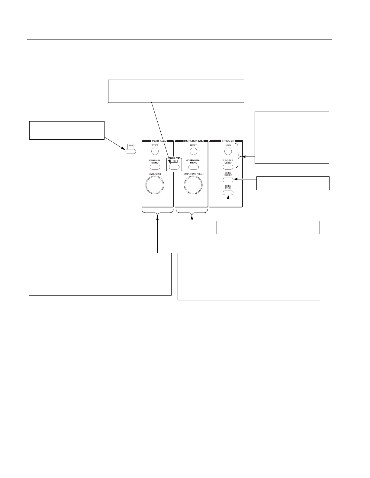
Operating Basics
RUN button
Enables waveform output. The signal
output depends on the RUN mode
settings.
QUICK EDIT button
Enters the QUICK EDIT mode from the waveform editor. This button
allows you to edit waveforms that have immediate effect on the output
signal. Use together with the VERTICAL and HORIZONTAL controls for
quick edit.
TRIGGER controls
Controls the trigger parameters.
Pushing the TRIGGER MENU button
displays the Trigger side menu. This
has the same effect as pushing
SETUP (front)→Tr ig ge r (bottom).
The LEVEL knob adjusts the trigger
level.
FORCE TRIGGER button
Pushing the FORCE TRIGGER button
generates an internal trigger event.
VERTICAL controls
Used to control the output vertical axis parameters.
Pushing the VERTICAL MENU button displays the VERTICAL side menu.
This is the same as selecting SETUP (front)→Vertical (bottom).
The OFFSET knob, adjusts the vertical offset.
The LEVEL/SCALE knob adjusts the amplitude.
Figure 2-3: Front panel trigger and output controls
FORCE EVENT button
Pushing the FORCE EVENT button generates an
internal event signal.
HORIZONTAL controls
Used to control the output horizontal axis parameters.
Pushing the HORIZONTAL MENU button displays the Horizontal side menu.
This is the same as selecting SETUP (front)→Horizontal (bottom).
The OFFSET knob adjusts the horizontal position.
The SAMPLE RATE/SCALE knob adjusts the clock frequency.
2-4 AWG615 Arbitrary Waveform Generator User Manual

Operating Basics
Rear Panel
Figure 2-4 show the rear panel signal and power connectors.
CAUTION. To prevent damage to the instrument, only apply signals within the
stipulated range to the INPUT connector.
Do not apply any external voltage to the OUTPUT connector.
AWG615 Arbitrary Waveform Generator User Manual 2-5

Operating Basics
TRIG IN connector
External trigger signal
input.
10 MHz REF IN connector
External 10 MHz reference
clock signal input.
10 MHz REF OUT connector
The internal 10 MHz clock reference signal is output when the
internal clock reference is selected. The external clock reference
signal is output when the external clock reference is selected.
The maximum output level is 1.2 V
EVENT IN connector
Inputs external event signals. This
signal can be used for sequence
control in Enhanced mode
into 50 Ω load
p-p
DISPLAY MONITOR OUT
connector
Connect to an external monitor.
AWG615
AWG615
100/10BASE-T connector
Connect to the Ethernet
network.
KEYBOARD connector
Connect to a standard PC
101-key keyboard.
IEEE STD 488 connector
A GPIB connector for remote
computer control through an
IEEE 488 standard parallel interface.
PRINCIPAL POWER SWITCH
Applies power to the standby circuit. In
addition to this switch being on, the front
panel ON/STBY switch must also be
turned on.
Power supply fuse holder
The 10 A fast blow and 5 A (T)
fuse are used for 115 V and
230 V systems, respectively
MASTER/SLAVE CONNECTION
These C (clock) and T (trigger) signals are used for only Synchronous
operation between Master unit and Slave unit.
The C OUT n clock signals supplied by Master are inputted into C IN
of Master and Slave.
Similarly, the T OUT n trigger signals supplied by Master are inputted
into T IN of Master and Slave.
VCO OUT connector
Sampling clock signal output.
The maximum output level is
0.4 V
into 50 Ω load
p-p
EXT CLOCK IN connector
External clock signal input.
An acceptable external clock
signal is
0.4 to 2.0 V
50±5 % duty cycle, and
125 MHz to 2.7 GHz frequency
range.
input voltage,
p-p
Power connector
Connect the provided power
cable to this connector.
Figure 2-4: Rear panel signal and power connectors
2-6 AWG615 Arbitrary Waveform Generator User Manual

Menu Operations
Operating Basics
This section describes the AWG615 Arbitrary Waveform Generator menu system
and numeric and text input methods.
Menu System
The AWG615 Arbitrary Waveform Generator uses menus to make selections.
There are four menu buttons, labeled EDIT, SETUP, APPL, and UTILITY, as
shown in Figure 2-5. Pushing a menu b utton displays the corresponding screen and
menu buttons. These menus let you edit waveforms, initialize instrument settings,
define instrument operation, and specify waveform output parameters.
You select items within the displayed menu by pushing the bottom or side bezel
button nearest to the menu item. These buttons consist of se ven bottom butt ons and
five side b uttons, as shown in Figure 2-5. These menu bezel buttons are referred to
as bottom menu buttons (or bottom buttons) and side menu buttons (or side
buttons).
The CLEAR MENU button cancels the current menu operation, clears the current
menus from the screen, and exits to the previous instrument state.
Menu buttons
AWG710B
ARBITRARY WAVEFORM GENERATOR 4.2 GS/s
Side menu bezel buttons
Bottom menu bezel buttons
(bottom buttons)
(side buttons)
CLEAR MENU button
Figure 2-5: Menu buttons, bezel menu buttons, and the CLEAR MENU button
AWG615 Arbitrary Waveform Generator User Manual 2-7

Operating Basics
Menu Elements
Pushing a front–panel menu button displays the screen and bottom menu items
associated with the button. You select a bottom menu item by pushing the button
directly below that menu item.
Pushing a bottom button displays a side menu, pop–up menu, list, or dialog box.
Figures 2-6 through 2-8 show examples of the side menu , pop–up menu and dialog
box, respectively.
Status display
Side menu
Bottom menu
Figure 2-6: Bottom and side menus
You use a side menu button to display a side submenu, set a parameter, perform a
task, or cancel an operation. Table 2-1 describes the side menu button types.
2-8 AWG615 Arbitrary Waveform Generator User Manual

Table 2-1: Side menu elements
Menu items Description Menu items Description
Operating Basics
Executes the displayed function
immediately.
Switches between two
parameters each time the side
button is pushed.
Allows entering numeric values
using the numeric buttons or the
general purpose knob.
Cannot be used in the current
instrument state (menu item is
grayed out).
Allows making selections by
using the general purpose
knob.
Displays submenus. Note that
the label on the item is followed
by an ellipsis (...).
The pop–up menu example, shown in Figure 2-7, displays a list of choices from
which you make a selection. Use the general purpose knob or the front–panel arrow
buttons to move up or down in the list. Push the OK side button or the ENTER
front–panel button to confirm the selected item.
Figure 2-7: Pop–up menu example
AWG615 Arbitrary Waveform Generator User Manual 2-9

Operating Basics
The dialog box example, shown in Figure 2-8, displays a form in which you make
selections or enter values. Use the front–panel arrow buttons to select items or
fields. A selected field or item is highlighted. Use the k eypad buttons or the general
purpose knob to change values in selected text/numeric fields or change 1–of–N
fields. A 1–of–N field contains two or more choices of which only one can be
selected at a time.
Push the OK side button to confirm the dialog box. Push the Cancel side button or
the CLEAR MENU button to exit the dialog box without making any changes.
Text/Numeric fields
1-of-N choice
Figure 2-8: Dialog box example
Refer to Numeric Input on page 2-11 and Text Input on page 2-13 for more
information on selecting and entering values in menus and dialog boxes.
Refer to Menu Structures on page 3-3 for information on the menu system.
2-10 AWG615 Arbitrary Waveform Generator User Manual

Numeric Input
Operating Basics
You can enter numeric values by using either the numeric keypad or the general
purpose knob. If the side menu item displays a v alue, you can alter this v alue using
the general purpose knob or numeric buttons.
Pushing the type of side menu button or selecting a parameter in a pop–up menu
causes the current setting to appear on the right end of the Status Display area as
shown in Figure 2-9.
Knob icon
Underscore
The General Purpose Knob
The Numeric Keypad
Figure 2-9: Knob icon displayed in Status Display area
A knob icon with a numeric value that includes an underscore character indicates
that you can change the value at the underscore location by using the general
purpose knob or keypad buttons. By def ault, the underscore character is positioned
under the digit specified depending on the parameters. You can only change the
value represented by the digits at and to the left of the underscore. Use the a and '
arrow buttons to move the underscore to the desired position, and then turn the
general purpose knob to change the value.
If the numeric value has the knob icon, but does not have the underscore, then
turning the general purpose knob cycles through a predefined set of values.
When using the general purpose knob, v alues you change in side menus and menu
screens take effect immediately. Values in pop–up menus are not effective until
you push the OK side button or the ENTER front–panel button.
Figure 2-10 shows the numeric keypad, with descriptions of the b utton operations.
AWG615 Arbitrary Waveform Generator User Manual 2-11

Operating Basics
The SHIFT button enters a character
labeled in blue. Push the SHIFT button
and then push the keypad button.
The CLR button
deletes all characters
in the current field.
The DELETE button deletes the
character to the left of the caret.
The ENTER button
enters the current value
into the instrument.
Figure 2-10: Keypad buttons
The G, M, k, m, µ, n, and p are unit buttons. The A, B, C, D, E, and F buttons are
used for entering hexadecimal values.
To use the numeric keypad to enter a value, position the caret to where you want
to change a value, and then push a keypad button. If you want to enter a unit value
labeled in blue just above each numeric button, push or hold down the SHIFT
button, and then push the corresponding numeric button.
To enter or change more than one character, move the caret to the next position to
change. When you are done entering values, push the ENTER button to confirm
the changes and enter them into the instrument. For example, to enter 200.5 µs,
push 2, 0, 0, ., 5, SHIFT and 4 (µ) buttons in this order.
When you enter a value larger than the maximum value in the range for the
parameter, the parameter will be set to the maximum value. When you enter a v alue
smaller than the minimum value, the minimum value will be set in the parameter.
To set to the maximum or minimum value, enter a larger value or smaller value.
This is useful when you do not know the range that can be set.
Note that the current unit is always kept when you just use the ENTER after
entering digits. For example, suppose that the Clock is currently set to100.0 MS/s.
When you press the 5, 0 and ENTER buttons in this order , the Clock will be set to
50.0 MS/s. To set the Clock to 500 kS/s, press 0, ., 5 and ENTER b uttons, or 5, 0,
0, SHIFT, and 8 (k) buttons in this order.
2-12 AWG615 Arbitrary Waveform Generator User Manual

Text Input
Operating Basics
When you need to assign a name to a waveform file or equation, or a IP address to
the instrument, the instrument displays a text dialog b ox. See Figure 2-11. The text
field is where you enter or change an existing character s tring. The character palette
is where you select alphanumeric characters to insert into the text field. You can
also select equation or file names from the name list to insert into the text field.
Caret
Tex t fi el d
Character palette
Name list
Text field
Character palette
Text field
Figure 2-11: Three type of Input text dialog boxes
To select a character from the character palette, use the general purpose knob to
highlight a character, and then push the ENTER to insert the character into the text
field. Repeat this step until you have entered all characters in the text field. By
default, the character palette is selected. To select text from a file name list, use the
y and b arrow buttons to move the knob icon to the file name list. Table 2-2
describes all the controls you can use for entering and editing text.
AWG615 Arbitrary Waveform Generator User Manual 2-13

Operating Basics
Shortcut Controls
Table 2-2: Text input button functions
Control Description
General purpose knob Selects the character to insert into the text field.
a and ' arrow buttons Moves the character insertion caret left or right in the text field.
ENTER button Inserts the selected character or character string into the text field.
button Deletes one character to the left of the caret.
CLR button Clears the entire text field.
Numeric buttons Enters numeric characters into the text field.
SHIFT button Enters a selected character in upper case. When you push the SHIFT
button, the SHIFT LED lights. When the dialog box disappears, the
SHIFT LED also goes off.
Figure 2-12 shows the shortcut buttons and knobs that control specific instrument
setup parameters. Using the shortcut controls lets you adjust the output setup
parameters even while you are displaying another menu. Table 2-3 describes the
shortcut controls.
Figure 2-12: Shortcut controls
2-14 AWG615 Arbitrary Waveform Generator User Manual

Table 2-3: Shortcut controls
Controls Description
VERTICAL
Displays the Vertical side menu. This is the same operation as selecting
SETUP (front)!Vertical (bottom).
Adjusts the vertical offset parameters. This is the same as selecting
SETUP (front)!Vertical (bottom)!Offset (side), and then turning the
general purpose knob. (except option 02)
Adjusts the amplitude parameters. This is the same as selecting SETUP
(front)!Vertical (bottom)!Amplitude (side), and then turning the
general purpose knob.
HORIZONTAL
mp
Displays the Horizontal side menu. This is the same as selecting SETUP
(front)!Horizontal (bottom).
Adjusts the clock setting. This is the same as selecting SETUP
(front)!Horizontal (bottom)!Clock (side), and then turning the
general purpose knob.
Operating Basics
TRIGGER
Displays the Trigger side menu. This is the same as selecting
SETUP (front)!Tri gg er (bottom).
Adjusts the trigger level setting. This is the same as selecting
SETUP (front)!Tri gg er (bottom)!Level (side), and then turning the
general purpose knob.
AWG615 Arbitrary Waveform Generator User Manual 2-15

Operating Basics
File Management
This section is an overview of the instrument commands and oper ations for doi ng
file management tasks. Refer to File Management on page 3-225 for more
information.
File Type Extensions
The AWG615 Arbitrary Waveform Generator uses numerous file formats to hold
different types of data. These file types are listed in Table 2-4. Note that the
instrument checks the file format and processes the file based on its content,
regardless of the file extension.
Table 2-4: AWG615 Arbitrary Waveform Generator file types
Files Description
Waveform file Use .wfm or .WFM suffix for identification.
Contains waveform data. All signal data must be in waveform format before it
can be output. Created with the waveform editor, by compiling an equation file,
or by converting to waveform format when importing waveforms from external
equipment.
Pattern file Use .pat or .PAT suffix for identification.
Contains pattern data. Created with the pattern editor.
Sequence file Use .seq or .SEQ suffix for identification.
Contains waveform sequence and trigger data. Created with the sequence
editor.
Equation file Use .equ or .EQU suffix for identification.
Contains equations or functions that describe a waveform. Created with the
equation/text editor. Both text editor and equation editor assign .txt suffix by
default, but use .equ suffix to avoid confusion with normal text file.
Text file Use .txt or .TXT suffix for identification.
Contains ASCII text. Created with the equation/text editor.
Setup file Use .set or .SET suffix for identification.
Contains instrument setup and configuration data of both AWG and FG mode.
Created from the SETUP menu.
2-16 AWG615 Arbitrary Waveform Generator User Manual

Operating Basics
Locating Files
There are three locations for storing waveform data on the AWG615 Arbitrary
Waveform Generator. Data can be stored on the instrument hard disk drive, the
instrument floppy disk drive, or a remote storage device accessible through the
Ethernet interface. If the file you want to load is not on the current drive, use the
EDIT menu main screen Drive and Directory bottom menu buttons to open side
menus that let you change the current drive locatio n. Table 2-5 describes the Drive
and Directory bottom buttons.
Table 2-5: Drive and Directory menus
Bottom
menu
Drive Main
Directory Up Level
Side menu Description
Changes the instrument current drive. To select a drive, push
Floppy
Net1
Net2
Net3
Down Level
the appropriate side menu button. Note that there must be a
floppy disk inserted in the instrument floppy disk drive to select
the floppy drive.
Note that the label Net1, Net2 and Net3 vary depending on the
net name settings in the UTILITY menu.
Moves up a directory level.
Moves down a directory level. To move down a directory level,
select a directory name in the pop–up list, and then push the
Down Level side button. The filename list changes to show the
contents of the directory.
Make Directory
Archive
Extract
NOTE. In the following procedures, you may have to push the EDIT button twice
Creates a directory at the current level. To create a directory,
push the Make Directory side button to display the Input New
Directory Name dialog box. Enter the directory name in the
name field, then push the OK side button. The instrument
creates the new directory.
Creates a new file (.tar format) for archive from selected
directory. The archived file keeps hierarchic structure.
Restore the archived file (.tar) to the current directory.
to quit the editor. When the instrument does not display the file list, push the EDIT
button again. Refer to Saving Files on page 2-20.
AWG615 Arbitrary Waveform Generator User Manual 2-17

Operating Basics
Copying Files
Renaming Files
Do the following steps to copy a file (single window):
1. Push EDIT (front).
The instrument displays the file list.
2. Select the file to copy.
3. Push File (bottom)!Copy (side)
4. Enter the new name for the copied file in the file name field
5. Push OK (side).
The file is copied and renamed. Also refer to page 3-230 for more information
on the double windows.
NOTE. You can copy a file or all files in another way. Refer to Copying Files on
page 3-227 for those methods.
Y ou can also move a file or all files. Refer to Moving Files on pa ge 3-228 f or those
methods.
Renaming files is similar to Copying f iles, but the original f iles are deleted. Do the
following steps to rename a file:
1. Push EDIT (front).
The instrument displays the file list.
2. Select the file to rename.
3. Push File (bottom)!Rename (side).
4. Enter the new name for the file in the file name field.
5. Push OK (side).
The file is renamed.
2-18 AWG615 Arbitrary Waveform Generator User Manual

Operating Basics
Deleting Files
Read Only Attribute
Do the following steps to delete a file:
1. Push EDIT (front). The instrument displays the file list.
2. Select the file to delete.
3. Push File (bottom)!Delete (side). The instrument displays a message box
asking you to confirm deleting the file.
4. Push OK (side) to delete the file, or Cancel to cancel the operation and keep
the file.
You can also delete all files on the current drive and directory by doing the
following steps:
1. Push EDIT (front)!File (bottom)!Delete All (side).
The instrument displays a message box asking you to conf irm deleting all files.
2. Push OK (side) to delete all files, or Cancel to cancel the operation and keep
all files.
You can change the read only or read/write attributes on a file. Do the following
steps to change the file attribute:
1. Push EDIT (front).
The instrument displays the file list.
2. Select the file to change the attribute.
3. Push File (bottom)!Attribute xxxx (side).
The xxxx is the Read/Write or Read Only attribute of the selected file. Pushing
this side button immediately changes the file attribute.
The file with a read only attribute is marked by , and the directory by . See
Figure 2-13.
AWG615 Arbitrary Waveform Generator User Manual 2-19
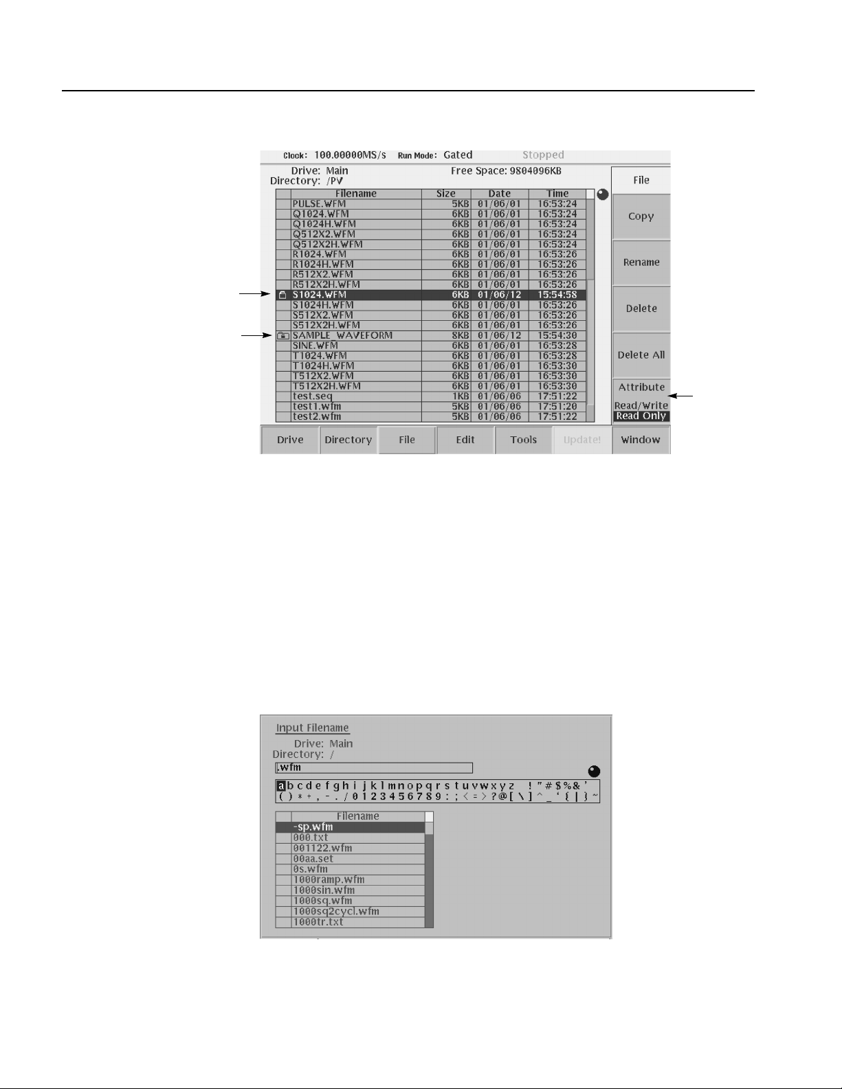
Operating Basics
File with read only
Directory with read only
Attribute
side button
Saving Files
Figure 2-13: Files and directories with read only attribute
You can save files from each editor screen. You have the choice of saving your
waveform data to the current file name or to a new f ile name. To save a wavefo rm
to its current file name, push File (bottom)!Save (pop–up)! OK (side).
If you are saving a waveform for the first time, the instrument opens the Input
Filename dialog box, shown in Figure 2-14. Use this dialog box to enter a file
name. If necessary, you can select a different storage media or directory by pushing
the Drive... side menu button. Enter the file name, then push the OK side b utton or
the ENTER front–panel button to close the dialog box and save the file.
Figure 2-14: Input Filename dialog box
2-20 AWG615 Arbitrary Waveform Generator User Manual

Operating Basics
NOTE. When you exit an editor without saving edited data, the instrument displays
the message Save the changes you made? Push the Yes side button to save the
waveform data.
To save waveform data to a new file name, push File (bottom)!Save As
(pop–up)!OK (side). The instrument opens the Input Filename dialog box, sho wn
in Figure 2-14. Use this dialog box to enter a file name. If necessary, you can select
a storage media or directory by pushing the Drive... side menu b utton. Enter the file
name, then push the ENTER front–panel button to close the dialog box and save
the file.
If you are saving a file with a record length larger than 960 data points and the
record is not evenly divisible by four, the instrument needs to adjust the record
length to meet internal memory record length requirements. The instrument
displays one of the messages shown in Table 2-6. Y ou can push th e OK side button
to accept the recommended change, or cancel the save and then edit the file to
satisfy the data record length requirements.
Archive, Extract
Table 2-6: Waveform record length adjustment messages
Message Description
Leave as it is The data is saved, as it is, without making changes. The instrument will
display an error message if you try to load a file that does not meet the
instrument waveform constraints.
Append 0 With Level–0 data added after the data, a file with a data length meeting
the requirements is created.
Expand With the waveform data expanded, a file with a data length meeting the
requirements is created.
Expand with Clock With the waveform data expanded, a file with a data length meeting the
requirements is created. In addition, the clock frequency increases without
change in scaling factor. The settings are saved in the file.
Repeat With repetitions of the original data linked, a file with a data length meeting
the requirements is created. If the total length of the linked data exceeds
16M/32M (option 01) points, this will cause an error.
To archive or extract files, do the following steps.
Archive. When you select Directory in the file list, you can make archives for all
the files in the directory and subdirectory.
1. Push EDIT (front).
The instrument displays the file list.
2. Select the file to make archive files.
AWG615 Arbitrary Waveform Generator User Manual 2-21

Operating Basics
3. Push Directory (bottom)!Archive (side).
The instrument displays the Input archive name dialog box. By default, the
name of <directory name>.tar is automatically assigned. If necessary, you can
change the name.
4. Push OK button, and the archive file will be created in the current directory.
Extract. The archived file is extracted (restored) to the current directory. If the
directory already exists, the existing file will be overwritten.
1. Push EDIT (front).
The instrument displays the file list.
2. Select the file to extract.
3. Push Directory (bottom)!Extract (side).
The instrument extracts the archived files and directories to current directory.
Remote computer archive operation. AWG615 Arbitrary Waveform Generator
uses .tar format files. Use the tar command when you archive with a remote
computer environment. If you are PC user, use tar format archive tool.
The following list describes some restrictions on archive and extract operation.
Blocking factor is 20.
The file name including the file path in the directory is up to 100.
The depth of directory hierarchy is up to 16.
Use the following command to make archive file:
tar [–] cvf <tar file name> <file name or directory name>
Use the following command to extract archive file:
tar [–] xvf <tar file name>
2-22 AWG615 Arbitrary Waveform Generator User Manual
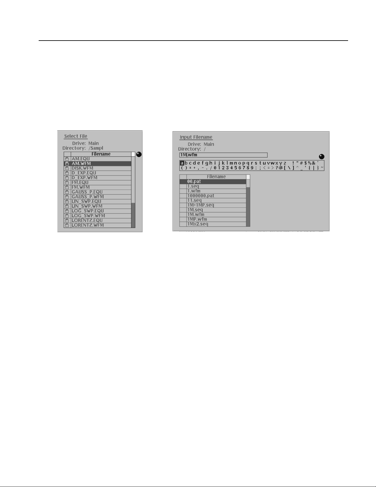
Quick View
Operating Basics
Before loading or handling a file, you sometimes want to look at the content of a
file to confirm the operation. The quick view function displays the view window
and allows you to view a waveform or pattern file selected in a file list. This
function is always available when a file list is displayed on the screen. See Figure
2-15.
Figure 2-15: File list window examples in which Quick View is available
Select a file from the file list window using the general purpose knob. Press the
SHIFT and ENTER front–panel buttons simultaneously. The view window
displaying the waveform or pattern appears as shown in Figure 2-16.
AWG615 Arbitrary Waveform Generator User Manual 2-23

Operating Basics
Figure 2-16: Viewing a file by Quick View function
Push the OK side menu button to close the view window. You cannot view files
other than waveform or pattern in this function.
This function is always available when a file list window or file list dialog box is
displayed on the screen.
2-24 AWG615 Arbitrary Waveform Generator User Manual

Editor Overview
Operating Basics
This section introduces the editor screen, describes the screen elements, and
discusses concepts common to most of the editors. Refer to the Reference section
for more detailed information about each waveform editor.
This section also provides an overview of the AWG615 Arbitrary Waveform
Generator waveform editors. There are five editors that provide the tools for
creating simple or complicated waveforms. Having more than one editor allows
you to create wavefo rms using your preferred metho d or the one best suited to the
waveform type.
The Edit menu, displayed by pushing the EDIT front–panel button, is the main way
to open editors. Most of the editor screens have common elements except for the
Sequence and Equation editors.
Editor Modes
The AWG615 Arbitrary Wav eform Generator provides f i ve editor modes, as listed
in Table 2-7. These editors let you create, edit, and sequence waveforms using the
technique best suited to your waveform. You can access these editors through the
main Edit screen, which is described on page 2-26.
Table 2-7: Editors
Editors Description
Waveform Editor Creates and edits analog waveforms.
Quick Editor Lets you modify and/or output, in real time, any part of a waveform you are
currently editing with the Waveform Editor.
Pattern Editor Creates and edits digital waveform patterns.
Sequence Editor Creates and edits tables that define the sequence and control conditions for
outputting one or more waveforms.
Text/Equation
Editor
Creates, edits, and compiles equation waveform definitions into a waveform
file. You can also use this editor to edit ASCII–format waveform data files
created by other equipment (such as Tektronix Digital Sampling
oscilloscopes).
AWG615 Arbitrary Waveform Generator User Manual 2-25

Operating Basics
Main Edit Screen
To display the main Edit screen, push the EDIT front–panel button. If there is no
waveform file currently loaded into the edit buffer, the instrument displays the
main Edit screen and a list of files in the current drive, as shown in Figure 2-17.
T able 2-8 lists the bottom menu button functions. If there is a wa veform loaded for
editing, the screen will show the loaded waveform in the appropriate editor.
File list
Figure 2-17: Main Edit screen
Table 2-8: Edit screen bottom menu buttons
Button Description
Drive Specifies the current drive to use for loading or storing waveform files
Directory Lets you navigate and create directories on the current drive
File Lets you copy, rename, delete, and assign attributes to files on the current
drive
Edit Displays the Edit side menu for editing existing or new waveform files
Tools Displays the Tools side menu for importing and converting file data
Update! Updates the waveform file name list. Becomes available during the file lists on
the Net Drive are displayed.
Window Lets you open a single window or double window that displays a file list of a
specified directory or drive. Refer to page 3-230 for information about double
windows.
2-26 AWG615 Arbitrary Waveform Generator User Manual

Operating Basics
Loading a Waveform File
to Edit
Creating a New Waveform
The default Edit screen displays a list of files in the current drive. To load a file and
open an editor window, use the general purpose knob or the front–panel arrow
buttons to highlight a file name. Then push the ENTER front–panel button. The
instrument loads the selected file and opens the editor appropriate for that file type.
You can also edit an existing file by selecting the file in the list, pushing the Edit
bottom button, then pushing the Edit side button. This process takes two more
steps than that described previously. If the file you want to edit is located in a
different directory of the hard disk drive, on a floppy disk, or on a network drive,
use the bottom menu Drive, Directory, and File buttons to change the current drive
and load a file from another location. Refer to File Management on page 2-16 for
information on locating and saving files.
To create a new waveform file, push the Edit bottom menu button. This displays
the Edit side menu items as shown in Figure 2-18. T able 2-9 provides an ov ervie w
of the Edit side menu button functions.
Edit
selected
file
Figure 2-18: Edit top level menu screen with Edit side menu
Create
a new
waveform
AWG615 Arbitrary Waveform Generator User Manual 2-27

Operating Basics
Table 2-9: Edit side menu buttons
Button Description
Edit Loads the selected waveform file and opens the appropriate editor screen
New Waveform Opens a new Waveform Editor screen
New Pattern Opens a new Pattern Editor screen
New Sequence Opens a new Sequence Editor screen
New
Text/Equation Opens a new Equation Editor screen
Editor Screen Elements
Window number
Wavefor m
record length
Data edit/display area
Figure 2-19 shows elements that are common to many of the editor screens. What
elements are in an editor depends on which editor is open. The Reference section
describes each editor in detail. Refer to Figure 2-19 to familiarize yourself with the
common screen elements of most of the editors.
Right cursor
position
field and
data value
Status
Knob icon
Side
menu
Wavefor m
file name
Clock
frequency
Left cursor
position
field and
data value
Cursor-to-cursor
distance
(edit area)
Run
mode
Position of data
viewed in overall
waveform record
display area
Active
cursor
position
Marker display
Bottom menu
Figure 2-19: Editor screen elements
2-28 AWG615 Arbitrary Waveform Generator User Manual

Operating Basics
Cursors and Editing
The edit window cursors define the data affected by all edit operations except the
T ools menu commands. Most of the edit commands affect the data located between
the left and right cursor positions. This region is called the edit area or scope.
Figure 2-20 shows an example of an edit area. In this example, all data is located
from left cursor position 300 to right cursor position 779.
Other edit operations use the active (selected) cursor position for inserting
waveform data. The active cursor is shown as a solid vertical line. The inactive
cursor is shown as a dashed vertical line.
Left cursor, (active)
selected
Edit
area
Edit area
Left cursor, 300
position (active)
Right cursor, 779
position
(inactive)
Figure 2-20: Cursors and edit area
When you edit a waveform, you must first specify the edit area or a single cursor
position, depending on the operation you want to do. To select the active cursor,
push the TOGGLE front–panel button to switch between the left and right cursor.
To move a cursor, turn the general purpose knob, use the left or right arrow keys,
or use the keypad or keyboard to enter a position in the cursor position field. The
cursor position field is active when the corresponding cursor is active.
AWG615 Arbitrary Waveform Generator User Manual 2-29

Operating Basics
Followings are more cursor operations that are a vailable by using the SHIFT b utton
on the front–panel:
Push the SHIFT front–panel button then turn the general purpose knob to
accelerate the cursor transfer speed.
Push the SHIFT front–panel button then push the TOGGLE front–panel
button to move the inacti ve cursor to the activ e cursor position (the two cursors
overlap).
Push the SHIFT front–panel bu tton then push the ENTER front–panel button
to move left cursor to 0 point and to move the right cursor to the maximum
point.
Multiple Editor Windows
The AWG615 Arbitrary Waveform Generator can open and edit up to three
waveform and/or pattern files, in any combination. The wa veform data is displayed
in separate windows, with each window stacked ve rtically on the screen. Multiple
editor windows are very useful for creating a ne w wav eform by cutting and pasting
waveform data from other files. Figure 2-21 shows an example of three opened
editor windows (one pattern and two waveform files).
Figure 2-21: Multiple editor windows
2-30 AWG615 Arbitrary Waveform Generator User Manual

Operating Basics
NOTE. You cannot open a sequence, text, or equation file from the Waveform or
Pattern Editor. If you are in the Waveform or Pattern Editor, you must exit to the
EDIT menu main screen and then load the sequence, text, or equation file.
Some editor information is not displayed when three Waveform editor windows are
open.
Opening Multiple Editor Windows. Do the following steps to load waveform data
file into an editor window:
1. From the editor screen, push File (bottom)!Open... (pop–up)!OK (side).
The Select File dialog box appears. If you cannot select the Open... menu item,
you already have three windows opened.
2. Select a waveform or pattern file from the Select File list.
If necessary, use the Drive..., Up Level, or Down Level side menu to select
the location where the file to load is located.
3. Push the OK side button.
The instrument opens a new windo w for the waveform or pattern data, stacking
the windows vertically to fit on the screen. If you attempt to load a sequence,
text, or equation file, you will receive an error message.
Creating a New Waveform or Pattern in a Multiple Editor Window. To create a new
empty W a veform or P attern Editor windo w , pu sh File (bottom)! New W a vef orm
or New Pattern (pop–up)!OK (side). The instrument opens a new window for
the waveform or pattern editor , stacking the windows v ertically to fit on the screen.
If you cannot select the New Waveform or New Pattern pop–up menu item, you
already have three editor windows opened.
Selecting the Active Edit Window. Although you can have up to three open editor
windows, you can only do editing tasks in one window at a time. To select the
active window, push Window (bottom)!Window1, Window2, or Window3
(side). All editing operations will affect the waveform data in that window until
you change to another editor window.
AWG615 Arbitrary Waveform Generator User Manual 2-31

Operating Basics
Quitting Editors
There are three methods to quit an editor.
Using the File Bottom Menu.
1. Push File (bottom)!Close (pop–up) to quit the waveform and pattern editors
or
push File (bottom)!Close (side) to quit the sequence and text/equation
editors.
2. If you have made no modifications to th e data, the editor is immediately exited.
If you have made modif ications, the message box Save the c hanges you made?
appears. Push the Yes, No, or Cancel side button.
Using the Window Bottom Menu.
You can close the window by using Window (bottom) menu for waveform editor
and pattern editor.
1. Push Window (bottom) ! Close Selected Window or Close Unselected
Window (side).
Close Selected Window closes current window and Close Unselected
Window closes the window which is currently unselected.
2. If you have made no modifications to th e data, the editor is immediately exited.
If you have not saved the data after modifications, the message box Save the
changes you made? appea r s. Push Yes, No, or Cancel side button.
Using the EDIT Button.
1. Push EDIT button on the front–panel.
2. If you have made no modifications to th e data, the editor is immediately exited.
If you have not saved the data after modifications, the message box Save the
changes you made? appea r s. Push Yes, No, or Cancel side button.
Refer to page 2-20 for saving files.
2-32 AWG615 Arbitrary Waveform Generator User Manual
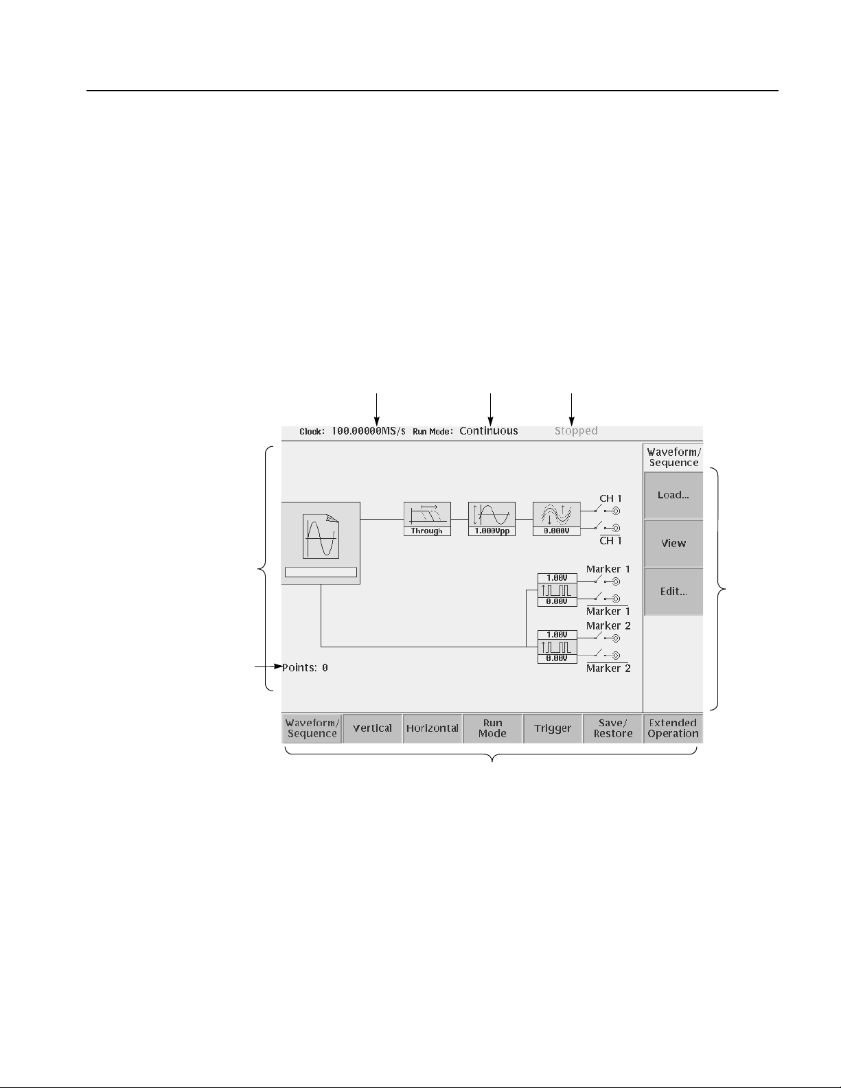
Setup Overview
Operating Basics
The Setup screen is where you load and set up the waveform for output. This
section gives you an overview of the Setup screen, how to load a file, how to set
the signal output parameters, and how to enable signal output. Refer to The Setup
Menu on page 3-33 in the Reference section for more information.
Main Setup Screen
Wavefor m
parameter icons
Number of points for
loaded waveform
To display the main Setup screen, push the SETUP front–panel button. The
instrument displays the main Setup screen as shown in Figure 2-22. Table 2-10
describes the screen waveform parameter icons. Table 2-11 lists the bottom menu
functions.
Clock frequency Run mode Instrument status
Side
menu
area
Bottom menu
Figure 2-22: Main Setup screen (except option02)
AWG615 Arbitrary Waveform Generator User Manual 2-33

Operating Basics
Table 2-10: Setup screen parameter icons
Icon Description Icon Description
Displays the file name of the
waveform, pattern, or
sequence file loaded for
output.
Note: use the View button to
display the loaded waveform.
Displays the lowpass filter
setting through which the
waveform is passed.
(except option 02)
Displays the peak–to–peak
signal amplitude setting.
Displays the signal offset
setting.
(except option 02)
Displays the digital output and
marker signal minimum and
maximum voltage settings.
Indicates that the channel
output is enabled or disabled.
If the switch is shown open,
that channel output is
disabled.
Indicates that the marker
output is enabled or disabled.
All Marker outputs are
controled by the ALL
MARKER OUT ON/OFF
button.
Table 2-11: Setup bottom menu buttons
Bottom menu
button
Waveform/Sequence Displays the side menu for loading, viewing, editing waveform files, and for
Vertical Displays the Vertical side menu for setting waveform peak–to–peak
Horizontal Displays the Horizontal side menu for setting the clock source, clock
Run Mode Displays the Run Mode side menu for setting the instrument run mode.
Trigger Displays the Trigger side menu for setting trigger source, slope, level,
Save/Restore Displays the Save/Restore side menu to save and restore setup output
Extended Operation Displays the Extended Operation side menu to change the operation mode
Description
entering the FG mode main screen.
amplitude, offset, lowpass filter, marker, and other output parameters.
The product which has option 02 doesn’t have offset and lowpass filter
function.
frequency, and marker signal delay parameters.
Refer to Run Modes in the Reference section for an explanation of the
different run modes.
external trigger impedance, and interval parameters.
parameters.
such as FG mode, Waveform Mixing mode and Synchronous Operation
mode.
2-34 AWG615 Arbitrary Waveform Generator User Manual
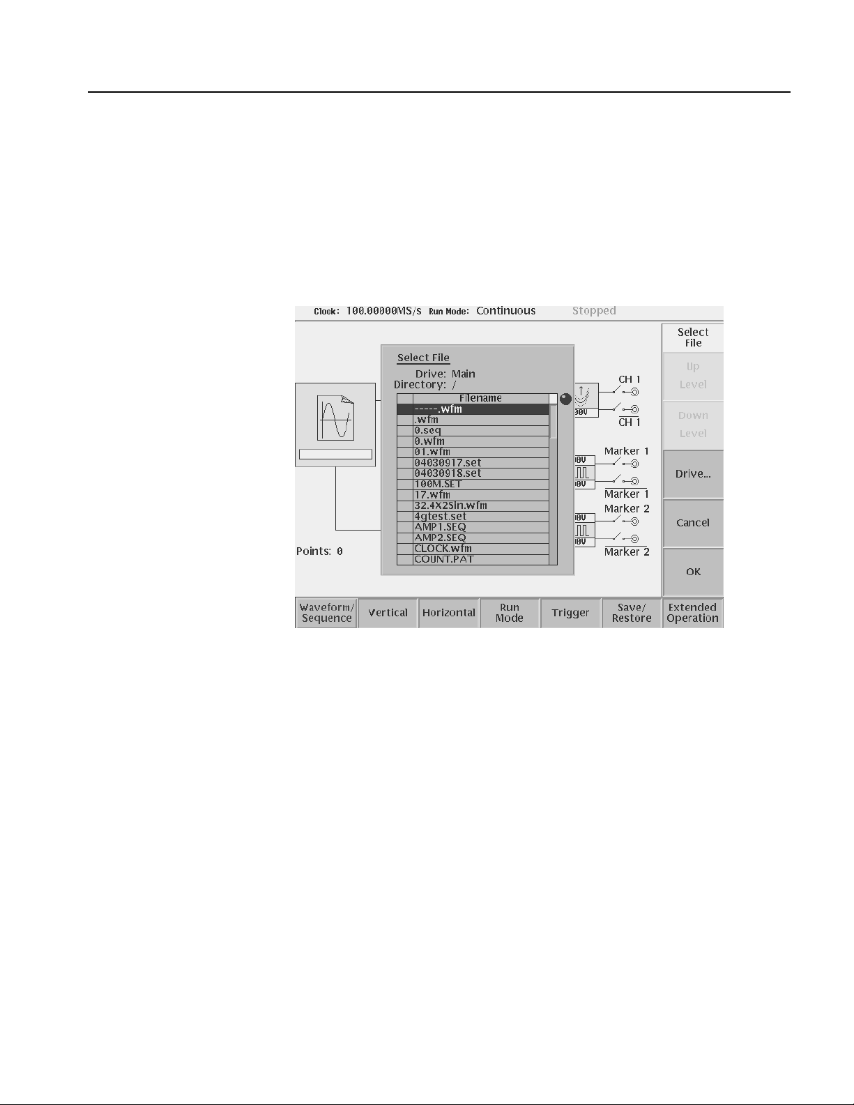
Operating Basics
Loading a Waveform File
to Output
Do the following steps to load a waveform file into the Setup screen:
1. Push the Waveform/Sequence bottom menu button.
This opens the Waveform/Sequence side menu.
2. Push the Load... side button. The instrument opens the Select File list as shown
in Figure 2-23.
Figure 2-23: Select File dialog on the Load menu
3. Use the general purpose knob or y and b arrow buttons to select the file name
to load. If the file you want to load is located in a different drive or directory,
use the side menu buttons to change the current drive.
4. Push the ENTER front–panel button or OK side button. The instrument loads
the file and displays the file name in the selected channel file icon. Push the
Cancel side button to exit the file load process.
The procedures above explains how to load a waveform or pattern into the
waveform memory, and/or sequence file into the sequence memory, which will be
scanned to output. The waveform memory, sequence memory and the edit buffer
are completely independent. So, you can edit a waveform, pattern, sequence or
equation/text while outputting an another waveform or sequence.
However, when you pus h SETUP (front–panel)!Waveform/Sequence
(bottom)!Edit (side) to copy the waveform in the waveform memory to the edit
AWG615 Arbitrary Waveform Generator User Manual 2-35
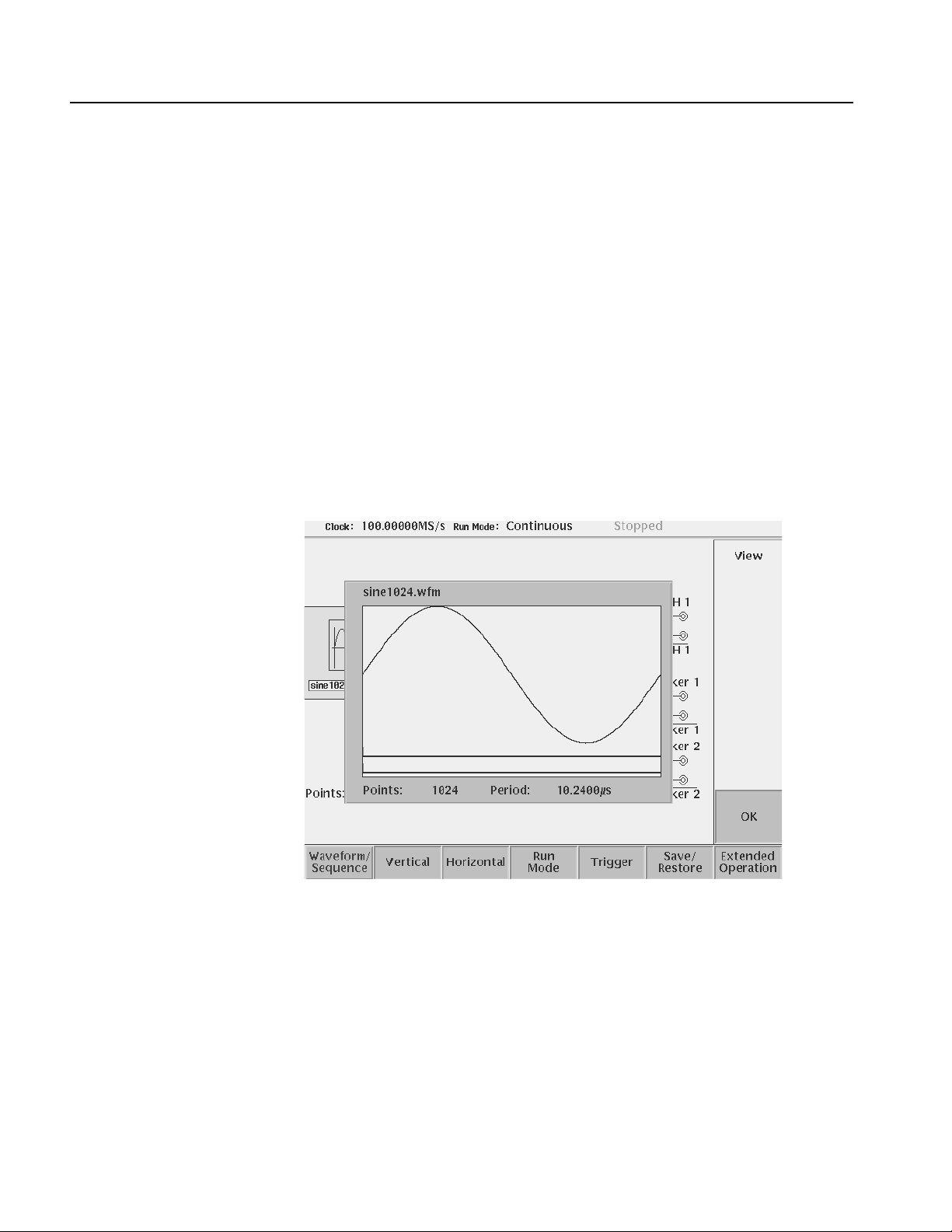
Operating Basics
buffer, you must save the currently edited waveform, pattern, sequence or
equation/text into a file.
You can enter into the QUICK EDIT mode only from the waveform editor. When
you enter into the quick edit mode, the instrument copies the data in the edit buffer
into the undo buffer. All the changes you make immediately reflect to the data in
the edit buffer, and also to the data in the waveform memory if that data is being
loaded to output.
Before loading, you can view a w a v eform or pattern. Refer to Quic k View on page
2-23 for more detail.
Viewing a Waveform
T o view the loaded w aveform file, push the View side menu button. The instrument
opens a window on the screen that displays the waveform, as sho wn in Figure 2-24.
Push the OK side menu button or ENTER front–panel button to close the view
window.
Figure 2-24: Viewing a file in the Setup screen
Note that the View function does not display the waveform in the waveform
memory , but displays the wa veform in the f ile that you specif ied. Even though you
change the waveform with the editor and update the wav eform memory, the View
function still displays the waveform before the update unless you save the file.
2-36 AWG615 Arbitrary Waveform Generator User Manual

Operating Basics
Editing a Waveform
Setting Waveform Output
Parameters
T o edit the loaded waveform f ile, push the Edit... side menu button. The instrument
opens the appropriate edit window for the previously loaded file type.
If you have not loaded a file in the Setup screen, the instrument displays the
message No output data, and you cannot enter into the editor.
The editors are described in more detail in the Reference section be ginning on page
3-55.
The Setup side menus provide commands for setting and adjusting waveform
output parameters. The steps for setting output parameters are discussed in detail
in the Reference section be ginning on page 3-33. Table 2-12 provides an overvie w
of the Setup side menu operations.
Table 2-12: Setup output parameter operations
Bottom
button
Wavefor m/S eq
uence
Side
button Description
Load...
View
Displays the Select File dialog box that lists files in the current
drive and directory. Select a file to load or use the side menu
buttons to change drives and/or directories.
Displays the loaded file in a window. Push the OK side menu
button to close the view window.
Edit...
Vertical Filter
Amplitude
Offset
Marker...
Output...
Opens the appropriate editor for the loaded file.
Selects lowpass filter to insert into signal path. Filter values
are Through (no filter), 20 MHz, 50 MHz, 100 MHz, and 200
MHz. Use the general purpose knob to enter new
values.(except option 02)
Sets the signal peak–to–peak amplitude in increments of
0.001 V. The maximum value is 2 V
V
in direct mode. Use the general purpose knob or the
p–p
keypad to enter new values.
Sets the signal offset value in increments of 0.001 V. The
offset voltage range is ±0.5 V. Use the general purpose knob
or the keypad to enter new values.(except option 02)
Displays a side menu to set Marker 1 and Marker 2 signal high
and low values. The marker signal voltage range is -2.0 V to
2.45 V and maximum amplitude is 1.25 V
the general purpose knob or the keypad to enter new values.
Toggles normal output to direct output.(except option 02)
in normal mode and 1
p–p
into 50 Ω. Use
p–p
AWG615 Arbitrary Waveform Generator User Manual 2-37

Operating Basics
Table 2-12: Setup output parameter operations (cont.)
Bottom
button
Horizontal Clock
Run Mode Continuous
Trigger Source
Side
button Description
Clock Ref
Clock Src
Triggered
Gated
Enhanced
Slope
(or Polarity)
Level
Impedance
Sets the clock sample rate from 50 kS/s to 2.7 GS/s.
Sets the reference clock source to either Internal or External.
A valid external clock signal is 10 MHz ±0.1 MHz with a
voltage level of 0.2 to 3.0 V
Sets the clock source to either Internal or External. A valid
external clock signal is 125 MHz to 2.7 GHz with a voltage
level of 0.4 to 2.0 V
Displays the Run Mode side menu for setting the instrument
run mode. Refer to The Run Mode Menu section on page 3-43
for an explanation of the different run modes.
Sets trigger source to Internal or External. If Exter nal selected,
all other side menu items are not selectable except Interval.
Sets the trigger slope or gate polarity to Positive or Negative.
Sets the trigger signal level. The trigger level range is ±5.0 V
in 0.1 V increments.
Sets the external trigger input line impedance to either 50 Ω
or 1 kΩ.
p–p
.
p–p
.
Outputting a Waveform
Interval
Save/Restore Save Setup
Restore Setup
Extended
Operation
FG...
Wavefor m
Mixing...
Sync Master...
Sync Slave...
Sets trigger interval from 1.0 µs to 10.0 s.
Save the setup parameters set by SETUP window and
Extended Operation mode window as a setup file.
Restore a setup file.
Enters the FG mode for easy generate of standard functional
waveform.
Enter the Waveform Mixing mode.
Enter the Sync-Master of the Synchronous Operation mode.
Enter the Sync-Slave of the Synchronous Operation mode.
T o output a loaded wa veform, push the CH 1 OUT and/or CH 1 OUT and/or ALL
MARKER OUTPUT ON/OFF front–panel button(s), then the RUN front–panel
button. The LEDs near each button light up to indicate they are enabled. The
instrument outputs the wav eform dependi ng on the Run mode. You can turn either
or both channel outputs and marker outputs on or off while the instrument is
running by pushing the CH 1 OUT or CH 1
OUT or ALL MARKER OUTPUT
ON/OFF buttons. To stop the waveform output, push the RUN button so that the
LED turns off.
2-38 AWG615 Arbitrary Waveform Generator User Manual

Operating Basics
Saving and Restoring
Setup Parameters
The waveform or pattern file contains only the waveform and clock information.
When you load a waveform or pattern file, the output signal will use the current
instrument setup parameters.
T o sa ve you from doing a manual setup procedure each time you load a wa veform,
the AWG615 Arbitrary Waveform Generator lets you sa v e setup parameters into a
setup file. You can then restore the saved settings for use with waveforms.
The setup parameters of the AWG mode and the Extended Operation mode are
saved in a setup file. When a setup file is restored, settings in both AWG mode and
Extended Operation mode will replace the contents of a setup file.
Do the following steps to save the current setup parameters:
1. Push SETUP (front)!Save/Restore (bottom)!Save Setup (side).
The Input Filename dialog box appears.
2. Enter a setup file name.
The setup file name must have the extension .set.
3. Push the OK side button.
The setup information is saved to the designated file.
Do the following steps to restore setup parameters from a file:
1. Select SETUP (front)!Save/Restore (bottom)!Restore Setup (side).
The message box displaying Restoring setup destroys current settings.
appears. The instrument then opens the Select Setup Filename dialog box.
2. Enter or select the setup file name to load.
3. Push the OK side button to load the file and restore the setup parameters, or
push the Cancel side button to exit the restore process without loading the
setup file.
AWG615 Arbitrary Waveform Generator User Manual 2-39

Operating Basics
Theory of Operation
This section presents an overvie w of the AWG615 Arbitrary Wa v eform Generator
hardware, data structures, and operating modes.
Block Diagram
Figure 2-25 show the main hardware blocks that make up the AWG615 Arbitrary
Waveform Generator.
CPU. The CPU controls the whole instrument using the GPIB interface, floppy disk
connection, 100/10BASE–T Ethernet connection, user interface through the
display screen and the front–panel, and so forth.
Clock Oscillator. You can select either the internal or external reference clock
source by using the SETUP horizontal menu.
If you select the external source, the reference signal connected to the 10 MHz REF
In connector on the rear panel will be used.
The internal clock is from the reference clock oscillator, which uses direct digital
synthesis (DDS). Figure 2-25 shows the clock oscillator configuration.
Trig g er C on t rol . The Trigger Control block controls the Memory Address Control
in the operation mode that you specified from the RUN MODE menu.
Waveform Memory and Shift Register. The Waveform Memory block has 8 bits for
waveform data and 2 bits per channel for markers, thus a total length of 32.4 M
/64.8 M (option 01) points. You can set any value from 960 points to 32.4 M/64.8
M (option 01) points for the length of waveform data. It must be in increments of 4.
The Shift Register block is used to provide waveform data from the DAC at a rate
up to 2.7 GS/s .
RUN modes. Selecting a RUN mode from the SETUP menu causes one of the
following to operate the AWG615 Arbitrary Waveform Generator:
Tabl e 2- 1 3 : R u n m o d es
Modes Descriptions
Continuous Consecutively output regardless of existence of a trigger signal.
Triggered The output signal is obtained only once when one of the following is input:
An external trigger signal from the rear panel’s TRIG IN connector.
A trigger signal generated with the front–panel’s FORCE TRIGGER button.
A trigger command from remote device.
2-40 AWG615 Arbitrary Waveform Generator User Manual

Operating Basics
Table 2-13: Run modes (cont.)
Modes Descriptions
Gated The waveform is output only while:
An external trigger signal from the rear panel’s TRIG IN connector.
A gate signal through the front–panel’s FORCE TRIGGER button is TRUE.
A control command such as trigger or event from remote device. (Except
the Synchronous operation mode)
Enhanced The waveform is obtained, in the order defined with the sequence, based on:
A trigger signal (for example, an external trigger signal from the rear panel’s
TRIG IN connector).
An event signal from the rear panel’s EVENT IN connector.
An trigger signal from the front panel’s FORCE TRIGGER button.
An event signal from the front panel’s FORCE EVENT button.
A control command such as trigger, event or jump from remote device.
(Except the Synchronous operation mode)
Extended operation. Selecting a Extended operation from the Extended Operation
menu causes one of the following to operate the AWG615 Arbitrary Waveform
Generator:
Table 2-14: Extended operation
Modes Descriptions
FG Enter the FG mode for easy generate of a standard functional waveform.
Wavefor m
Mixing
Synchronous
Operation
Create and output a mixed waveform. Waveform mixing
generates the wa vef orm which added the v alue f or ev ery point of
two waveforms, A and B, at a rate of a mixing ratio.
Synchronous Operation is a feature that outputs synchronized
two channels of signal using two units of AWG615. A word
synchronous called here means that two units of the AWG615
operate with the same clock and that start and stop of output
signals of two units are corresponding.
In the Synchronous Operation mode, the Clock and the Trigger
signals of two units are provided directly f rom the master unit. For
other signals, the master controls the slave through a LAN.
Analog Circuit. The Analog Circuit block contains the Filter, Attenuator, Output
Amplifier, Calibration and Offset Circuits. These circuits are used to process
signals generated from the DAC. Option02 has Calibration Circuits only.
AWG615 Arbitrary Waveform Generator User Manual 2-41

Operating Basics
Trigger
Control
Event
Address Control
Frequency
Control
Reference
Oscillator
Memory
Wavefor m
Memory
Phase
Comparator
Shift
Register
Analog
Output
Circuit
Clock
Output
Loop
Filter
1/2048
Divider
Figure 2-25: AWG615 block diagram
2-42 AWG615 Arbitrary Waveform Generator User Manual

Operating Basics
Memory Address Control. The Memory Address Control controls the addresses
used to read waveform memory data.
This block loads the first address of the waveform into the Address Counter that
was loaded into the waveform memory. It loads the waveform data length to the
Length Counter. The Address Counter specifies the point from which the
waveform was generated, and the Length Counter waveform ending position.
The Address and Length Counters operate with clocks produced by quarter
frequency–division for the clocks from the clock oscillator.
If the repeat count value has been loaded in the Repeat Counter, the waveform is
generated the specified number of times.
This block controls the sequence to the event signals generated in Enhanced Mode.
Start
Address
Sequencer
Wavefor m
length
Repeat
Count
Repeat
Counter
End of Waveform Clock
Length
Counter
Figure 2-26: Relationship between memory address control and waveform memory
Figure 2-26 shows the relationship between the memory address control and the
waveform memory.
Address
Counter
Wavefor m
Memory
AWG615 Arbitrary Waveform Generator User Manual 2-43

Operating Basics
Signal Edit Process
This subsection describes the signal edit process.
Load the desired waveform data to be output into the waveform memory. New
waveform data can be created using waveform editors incorporated in the
AWG615 Arbitrary Waveform Generator. New data can also be created by
combining the following:
A sample waveform data distributed with floppy disks.
Previously created waveform data on the built–in hard disk.
Waveform data measured or created by other equipment, which has been read
through the network.
Digital waveform data is loaded to the waveform memory location. The memory
address control extracts the waveform data from memory, including the clock
speed and the specified order of waveforms relative to the trigger event control.
Waveform Data Structure
When the AWG is in the Running mode, the digital output is processed through a
high speed digital to analog converter (DAC). The output then goes through the
analog output amplifier, to the offset and filter circuitry and to the output
connector.
The waveform data structure consists of analog waveform and digital pattern file
formats. The waveform file format includes 8–bits of resolution for the DAC
output and 2–bits for the digital marker output. The pattern file format includes
10–bits for digital output (The AWG615 supports 2 digital marker outputs). The
full–scale resolution of the 8–bit DAC is represented by -1.0 to +1.0.
Waveform and pattern files use different internal formats and editors. The
waveform file format is composed of 4–byte little endian and 1–byte for each data
point and markers. The 4–bytes point data is expressed as an IEEE floating point
number. The pattern data file is composed of 2–bytes including data and markers.
Waveform files contain floating–point numbers that maintain the mathematical
data precision necessary for waveform math operations such as multiplying,
dividing, adding, subtracting and so forth. Waveform files may be edited, but are
much larger for an equivalent record length compared to pattern files.
Pattern files are most useful for minimizing file size and file transfer time between
the AWG and a PC.
For more details about file format, refer to Data Transfer section in AWG615
Arbitrary Waveform Generator Programmer Manual.
2-44 AWG615 Arbitrary Waveform Generator User Manual

Operating Basics
Waveform Edit
T o enable editing, the AWG615 Arbitrary Waveform Generator provides you with
Waveform, Pattern, Sequence, Equation, and Text Editors. See Table 2-15 for the
explanations of those editors.
Tabl e 2- 1 5 : E d it o rs
Editors Descriptions
Waveform Editor The Waveform Editor lets you create or edit a waveform that is being displayed
on the screen. It enables you to create any waveform by an operation such as
cut and paste, partial inversion about the horizontal or vertical axis, shift, or
scaling. This operation can be based on a standard waveform, such as a sine
or rectangular wave, or the previously created waveform.
The Waveform Editor also has a unique feature that is capable of editing a
waveform with waveform calculation functions (absolute value of waveform,
differentiation/integration, convolution, correlation,
addition/subtraction/multiplication between waveforms and so on).
Pattern Editor The Pattern Editor displays a digital signal pattern with a pattern data placed in
8–bit creation waveform memory; it creates a digital signal pattern according to
the High/Low settings you made for the individual bits.
In addition to the functions supported by the Waveform Editor, the Pattern
Editor is capable of generating frequently used digital signals unique to digital
signals and pseudo random patterns.
Sequence Editor The Sequence Editor lets you create a more complex waveform by combining
a few types of the waveform data that you have created using Waveform and/or
Pattern Editors. This editor also enables a Waveform listing jump and output
stop to take place. They follow the external event information from the EVENT
IN connector as well as the number of repetitions and the order for the
individual pieces of waveform data.
Text Editor The Text Editor creates an equation, more exactly, a waveform by a method of
equations. When a equation has been created using this editor, you need to
perform compiling.
The Text Editor also enables you to edit a plain ASCII file. It should be used to
edit ASCII–format waveform data created with another equipment as well as
this instrument itself.
Quick Edit
The Quick Editor lets you modify and/or output any part of a waveform you are
currently editing with the Waveform Editor. This is done in real time. The data
between cursors can be scaled or shifted vertically and/or horizontally
(Expand/Shift).
AWG615 Arbitrary Waveform Generator User Manual 2-45

Operating Basics
2-46 AWG615 Arbitrary Waveform Generator User Manual

Tutor i a l s
This section contains tutorials to help you learn how to operate the AWG615
Arbitrary Waveform Generator. These tutorials provide a good introduction to the
following basic features of the instrument:
Setting up the instrument
Loading and outputting a sample waveform
Creating and editing standard function waveforms
Editing a waveform using quick editor
Using the equation editor
Creating and executing sequences
NOTE. These tutorial s do no t co ve r all the features and functions of the AWG615
Arbitrary Waveform Generator. They are intended only to introduce the basic
instrument functions.
By connecting an oscilloscope to the AWG615 Arbitrary Waveform Generator
and observing the waveforms output, you will understand how the AWG615
Arbitrary Waveform Generator works. The following equipment and accessories
are needed:
A digital storage oscilloscope
(A Tektronix TDS–Series oscilloscope or equivalent)
One 50 Ω SMA cable
One 50 Ω SMA terminator
One SMA (Fe)–BNC (Ma) adapter
Connect the digital storage oscilloscope to the AWG615 Arbitrary Waveform
Generator as shown in Figure 2-27.
NOTE. The CH1 LED is off when a signal is being output from CH1.
If the CH1
LED is on, turn off the output by pushing the CH1 OUT button.
AWG615 Arbitrary Waveform Generator User Manual 2-47
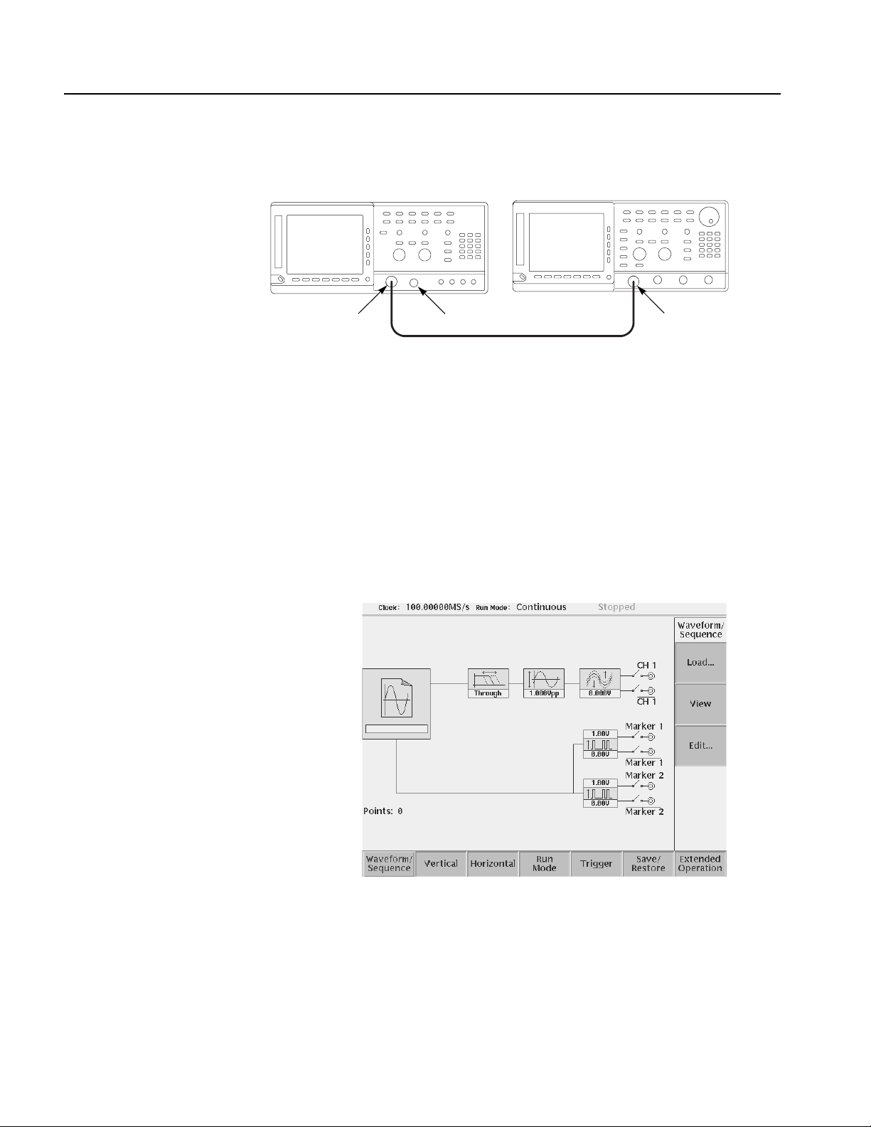
Tutorials
AWG615 Arbitrary Waveform Generator TDS-series oscilloscope
CH 1
50Ω SMA Terminator
50Ω SMA coaxial cable
SMA
(Female)-BNC
(Male) adapter
Figure 2-27: Cable connection between AWG615 Arbitrary Waveform Generator
and digital storage oscilloscope
Before beginning the tutorials, confirm that the instrument is installed correctly.
Refer to Installation on page 1-7.
Push the ON/STBY button to po wer on the instrument. Refer to Power On on page
1-12. The startup diagnostic routines will run and the instrument displays an initial
screen similar to that shown in Figure 2-28. You are now ready to perform the
tutorials.
Figure 2-28: Initial screen
If the instrument does not power on correctly or does not pass the power–on
diagnostics, contact the nearest Tektronix service center for help.
2-48 AWG615 Arbitrary Waveform Generator User Manual

Tutorial 1: Instrument Setup
This tutorial shows you how to do some instrument setups.
In this tutorial you will learn the following:
How to use the arrow button and general purpose knob
How to set the date and time
How to adjust the focused color
Tutorials
Display the UTILITY Menu
Do the following steps to display the system utility screen:
1. Press the UTILITY button on the front–panel to display the UTILITY menu.
2. Press the System bottom button (lower most–left button) on the bezel.
The instrument displays the system utility screen as shown in Figure 2-29.
System is
currently selected
Figure 2-29: System utility screen
AWG615 Arbitrary Waveform Generator User Manual 2-49

Tutorials
Set the Date and Time
Set the Focused Color
Do the following steps to set the year:
1. Repeatedly press the b button in the upper middle part of the front panel until
the Year: field is highlighted on the screen.
2. Turn the general purpose knob in the right upper corner of the front panel,
clockwise or counterclockwise until the word year is displayed.
When using the general purpose knob, note that the current displayed year in the
Year: field, is displayed in the upper right corner of the screen with the knob icon.
This means that you can adjust the value using the general purpose knob.
Do the following steps to set the month and day:
1. Press the b button once to highlight the Month:.
2. Use the general purpose knob to set the month.
3. Set the date in the Day: as was done in step 1 and 2 above.
4. Using the b button and the general purpose knob, set the hour, minute and
second in the Hour:, Min: and Sec:, respecti vely, as were done in step 1 above.
Do the following steps to set the focused color:
1. Repeatedly press the b button until the Hilight Color: is selected.
LCD Back Light
2. Turn the general purpose knob clockwise or counterclockwise while looking at
the screen until you get the color what you want.
The changes made during this tutorial take effect immediately. You can display the
system utility screen and adjust the focused color at any time without exiting current
tasks.
You have completed the Instrument Setup tutorial.
The default for the LCD back light is the on state.
Do the following steps to disable the LCD back light:
1. Repeatedly press the b button until the LCD Back Light is highlighted.
2. Press the a button or turn the general purpose knob to the left.
NOTE. The LED display state is saved when you turn the instrument off by pressing
the ON / STBY button.
Do the following to turn on the instrument display:
1. Press the ON/STBY button to power on.
2. Press the CLEAR MENU button on the front–panel twice.
You have completed the Instrument Setup tutorial.
2-50 AWG615 Arbitrary Waveform Generator User Manual

Tutorial 2: Loading and Outputting a Sample Waveform
This tutorial shows you how to load and output a waveform from the sample
waveform floppy disk pro vided with the AWG615 Arbitrary Wave form Generator.
In this tutorial you will learn the following:
How to select a drive
How to select and load a file
How to view a loaded file
How to output the loaded waveform file
Tutorials
Display the SETUP Menu
Do the following to display the SETUP menu:
Push the SETUP front–panel button to display the SETUP menu screen.
The SETUP menu screen is the initial power–on screen shown in Figure 2-28 on
page 2-48.
Do the following to select a drive:
1. Insert the sample waveform floppy disk into the drive unit to the left of the
screen.
2. Push the Waveform/Sequence bottom button to display the
waveform/sequence side menu.
This side menu contains three items: Load..., View, and Edit....
NOTE. The ellipsis (...) means that this menu item will display a submenu (side or
pop–up) when selected.
3. Push the Load... side button to display the Select File list, shown in
Figure 2-30.
Make sure that the subside menu displays Drive..., Cancel and OK items.
AWG615 Arbitrary Waveform Generator User Manual 2-51
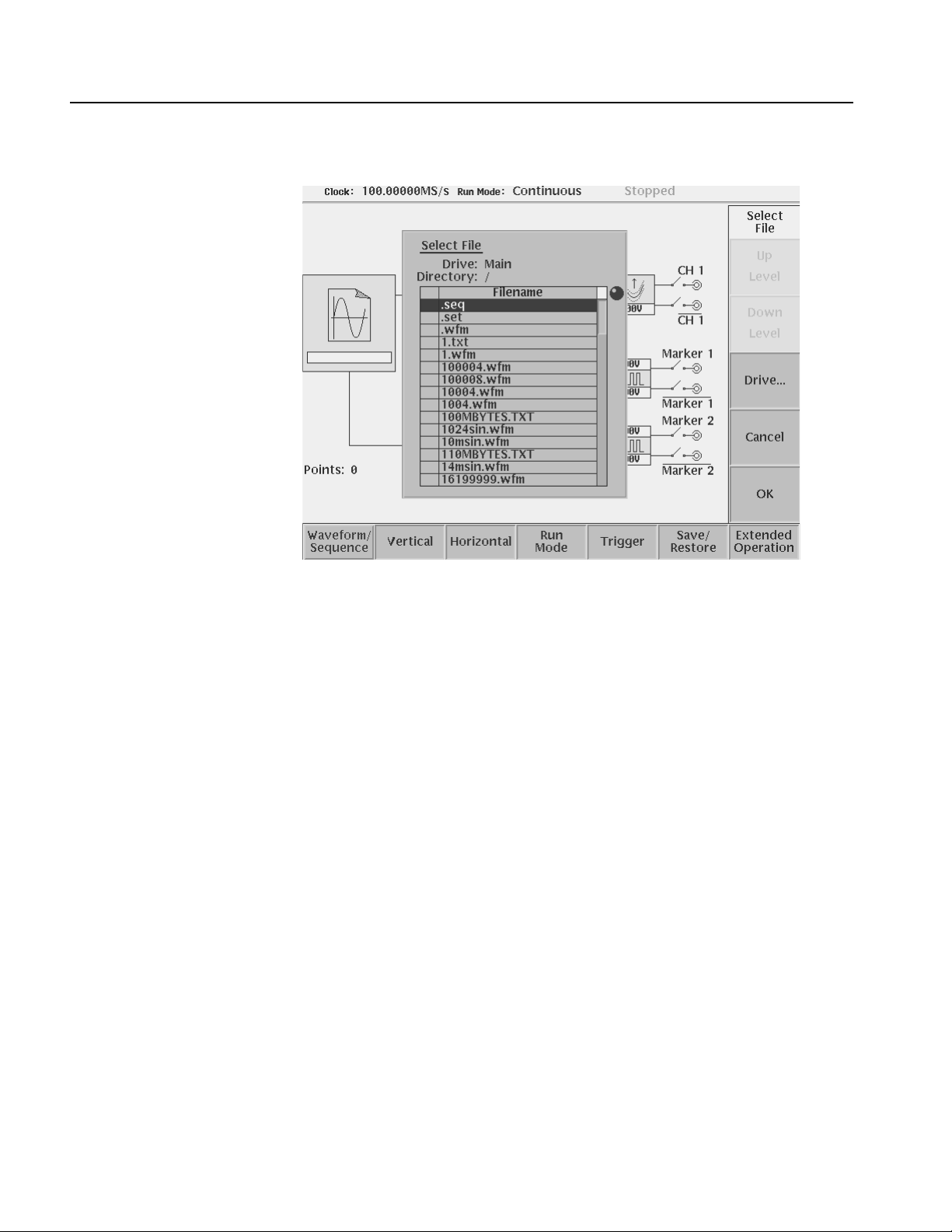
Tutorials
Load a Sample Waveform
Figure 2-30: The Select File list
4. Push the Drive... side menu button.
The Select Drive dialog box appears at the corner of the screen and the Drive...
side menu also appears. Note that the knob icon appears in the dialog box. This
means that you can use the general purpose knob to select a drive from the list.
5. Turn the general purpose knob or use the navig ation arrow b uttons to highlight
the word Floppy and then push the OK side button.
The dialog box now lists the files on the sample waveform floppy disk.
Do the following steps to load a sample waveform:
1. Turn the general purpose knob to select LIN_SWP.WFM from the file listing in
the dialog box.
2. Push the OK side menu button, and wait until the LED of the floppy disk dri ve
goes off.
This operation loads the selected waveform file into the instrument waveform
memory. Conf irm that 8000 is displayed in the Points: display field at the lower left
of the screen and that LIN_SWP.WFM is displayed in the WFM File: display field.
2-52 AWG615 Arbitrary Waveform Generator User Manual
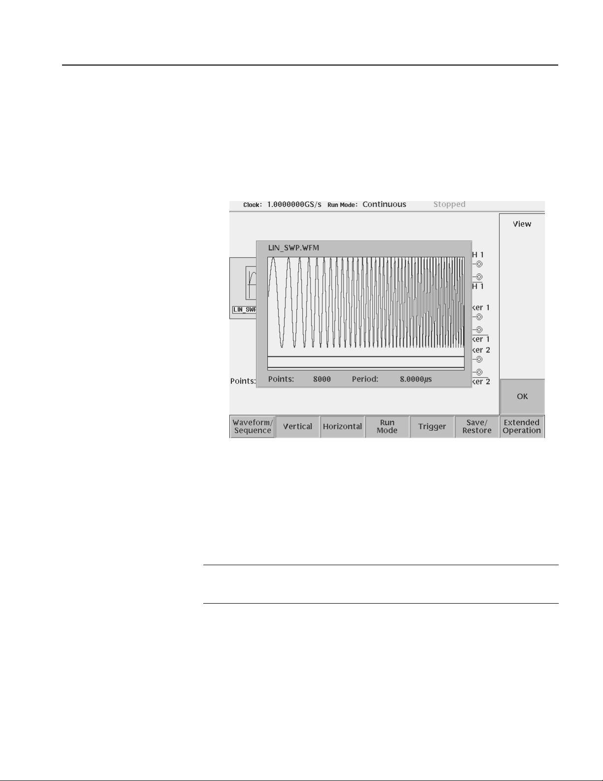
Tutorials
View the Sample
Waveform
Do the following steps to view the waveform you just loaded:
1. Push the View side menu button to display the waveform.
The waveform is displayed on the screen as shown in Figure 2-31.
2. When you are done viewing the waveform, push the OK side menu button to
exit the viewer.
Output the Waveform
Figure 2-31: Viewing a waveform loaded into memory
Do the following steps to output the waveform from the CH1 output connector:
1. Push the RUN button on the front–panel.
Pushing the RUN button causes the instrument to output the analog wa veform.
Push the RUN button again to stop the waveform output.
NOTE. You must push the RUN button to output a waveform. The instrument does
not automatically output a signal after loading a data file unless the instrument was
in the Run state when you loaded the new data file.
2. Push the CH 1 OUTPUT button near the CH1 output connector.
Pushing the CH 1 OUTPUT button connects the channel 1 output to the CH 1
connector. Push the CH1 OUTPUT button again to turn off the CH1 output.
3. If you connected an oscilloscope to the Wav eform Generator, observe that the
waveform on the oscilloscope is the same as that shown in Figure 2-31.
You have completed the Loading and Outputting a Sample Waveform tutorial.
AWG615 Arbitrary Waveform Generator User Manual 2-53

Tutorials
Tutorial 3: Creating and Editing Standard Function Waveforms
This tutorial shows you how to create a ne w wa veform by combinin g two standard
function waveforms in the waveform editor. You will create a sine wave and then
multiply the sine waveform by another sine waveform.
In this tutorial you will learn the following:
How to reset the instrument to factory defaults
How to open the waveform editor
How to create a standard function waveform
How to do a waveform mathematical operation
How to save and output the new waveform
Reset the Instrument
Open the Waveform Editor
Do the following steps to reset the instrument to factory default settings:
1. Push the UTILITY button on the front–panel to display the UTILITY menu
screen.
2. Push the Factory Reset side menu button.
The SETUP menu screen appears.
NOTE. If the Factory Reset side menu item is not shown, push the System bottom
menu button, and then push the Factory Reset side menu button.
3. Push the OK side button. The instrument is reset to the factory default setting.
Do the following steps to open the waveform editor screen:
1. Push the EDIT button on the front–panel.
2. Push the Edit bottom menu button.
3. Push the New Waveform side menu button.
The instrument displays the waveform editors initial screen as shown in Figure
2-32.
2-54 AWG615 Arbitrary Waveform Generator User Manual

Tutorials
Create a Sine Wave
Figure 2-32: Waveform editor initial screen
Do the following steps to create a standard sine function waveform:
1. Push the Operation bottom button.
The instrument displays the Operation pop–up menu.
2. Select Standard Waveform... from the pop–up menu by using the general
purpose knob.
By default, Standard Waveform... is selected.
3. Push the OK side button.
The instrument displays the standard function dialog box as shown in Figure
2-33.
AWG615 Arbitrary Waveform Generator User Manual 2-55

Tutorials
Figure 2-33: The Standard Function dialog box
4. Confirm that the knob icon is located to the right of the Type field items.
This is the default selection for this dialog box. If T ype is not selected, use the
y or b button on the front panel to select the Type field.
5. Turn the general purpose knob to highlight the Sine field item.
Note that Sine is the default selection.
6. Push the b button twice to select the Cycle field.
7. Turn the general purpose knob to set the cycle to 5.0.
8. Push the Enter button to enter the value in the field.
9. Push the OK side button.
You have created a five–cycle sine wave with a peak–to–peak range of 2.0 digital
to analog converter (DAC) units, as shown in Figure 2-34.
2-56 AWG615 Arbitrary Waveform Generator User Manual

Tutorials
Math Operation
Figure 2-34: Standard sine wave function created in the Waveform Editor
NOTE. The wa vefo rm amplit ude shown in the Waveform Editor does not directly
correspond to the output waveform volta ge amplitude. The levels in the Waveform
Editor correspond to the instrument 8–bit digital–to–analog convertor (DAC)
resolution. A signal with a -1.000 to +1.000 rang e utilizes the full r esolution of the
DAC circuit.
The actual output signal values (peak–to–peak and offset) are set in the Setup
menu. The Setup menu output values are multipliers, and assume that the edited
waveform signal uses the full ±1.000 waveform range.
Do the following steps to create a new waveform by multiplying the current sine
waveform with a second sine function waveform:
1. Push the Operation bottom button. The instrument displays the Operation
pop–up menu.
2. Select Standard Waveform... from the pop–up menu by using the general
purpose knob. By default, Standard Waveform... is selected.
3. Push the OK side button. The instrument displays the standard function dialog
box as shown in Figure 2-33.
4. Turn the general purpose knob to highlight the Sine item in the Type field.
Note that Sine is the default type menu selection.
5. Select Operation in the pop–up menu using the b button.
AWG615 Arbitrary Waveform Generator User Manual 2-57

Tutorials
6. Select Mul item using the general purpose knob.
7. Push the b button once to select the Cycle field.
8. Use the general purpose knob to set the number of cycles to 20.0.
9. Push the b button twice to select the Amplitude field.
10. Use the general purpose knob to set the amplitude to 1.0.
11. Push the OK side button to perform the multiply operation. This action
multiplies the sine wave in the waveform editor by the sine wave you have
specified in the Standard Function dialog box. Figure 2-35 shows the resulting
waveform.
Figure 2-35: Waveform created with the multiply operation
Save the Waveform
2-58 AWG615 Arbitrary Waveform Generator User Manual
Do the following steps to save the w aveform:
NOTE. To output the waveform in the waveform editor, you must first save the
waveform into a file and then load the file into the waveform memory.
1. Push the File bottom button.
The File pop–up menu appears.
2. Select Save from the pop–up menu using the general purpose knob.
 Loading...