


Service Manual
AWG615
2.7 GS/s Arbitrary Waveform Generator
071-1516-01
This document applies to firmware version 4.0
and above.
Warning
The servicing instructions are for use by qualified
personnel only. To avoid personal injury, do not
perform any servicing unless you are qualified to
do so. Refer to all safety summaries prior to
performing service.
www.tektronix.com

Copyright © Tektronix. All rights reserved. Licensed software products are owned by Tektronix or its suppliers and
are protected by United States copyright laws and international treaty provisions.
Tektronix products are covered by U.S. and foreign patents, issued and pending. Information in this publication
supercedes that in all previously published material. Specifications and price change privileges reserved.
TEKTRONIX and TEK are registered trademarks of Tektronix, Inc.
Contacting Tektronix
Tektronix, Inc.
14200 SW Karl Braun Drive
P.O. Box 500
Beaverton, OR 97077
USA
For product information, sales, service, and technical support:
In North America, call 1-800-833-9200.
Worldwide, visit www.tektronix.com to find contacts in your area.

WARRANTY 2
Tektronix warrants that this product will be free from defects in materials and workmanship for a period of one (1) year
from the dateof shipment. If any such product proves defective during this warranty period, Tektronix, at its option,
either will repair the defectiveproduct without charge for parts and labor, or will provide a replacement in exchange
for the defective product. Parts, modules andreplacement products used by Tektronix for warranty work may be new
or reconditioned to like new performance. All replaced parts,modules and products become the property of Tektronix.
In order to obtain service under this warranty, Customer must notify Tektronix of the defect before the expiration of
the warranty period and make suitable arrangements for the performance of service. Customer shall be responsible for
packaging and shipping the defective product to the service center designated by Tektronix, with shipping charges
prepaid. Tektronix shall pay for the return of the product to Customer if the shipment is to a location within the country
in which the Tektronix service center is located. Customer shall be responsible for paying all shipping charges, duties,
taxes, and any other charges for products returned to any other locations.
This warranty shall not apply to any defect, failure or damage caused by improper use or improper or inadequate
maintenance and care. Tektronix shall not be obligated to furnish service under this warranty a) to repair damage
resulting from attempts by personnel other than Tektronix representatives to install, repair or service the product; b) to
repair damage resulting from improper use or connection to incompatible equipment; c) to repair any damage or
malfunction caused by the use of non-Tektronix supplies; or d) to service a product that has been modified or integrated
with other products when the effect of such modification or integration increases the time or difficulty of servicing the
product.
THIS WARRANTY IS GIVEN BY TEKTRONIX IN LIEU OF ANY OTHER WARRANTIES, EXPRESS OR
IMPLIED. TEKTRONIX AND ITS VENDORS DISCLAIM ANY IMPLIED WARRANTIES OF
MERCHANTABILITY OR FITNESS FOR A PARTICULAR PURPOSE. TEKTRONIX' RESPONSIBILITY
TO REPAIR OR REPLACE DEFECTIVE PRODUCTS IS THE SOLE AND EXCLUSIVE REMEDY
PROVIDED TO THE CUSTOMER FOR BREACH OF THIS WARRANTY. TEKTRONIX AND ITS
VENDORS WILL NOT BE LIABLE FOR ANY INDIRECT, SPECIAL, INCIDENTAL, OR
CONSEQUENTIAL DAMAGES IRRESPECTIVE OF WHETHER TEKTRONIX OR THE VENDOR HAS
ADVANCE NOTICE OF THE POSSIBILITY OF SUCH DAMAGES.


Table of Contents
Specifications
General Safety Summary . . . . . . . . . . . . . . . . . . . . . . . . . . . . . . . . . . . . . . . . . . . . . . ix
Service Safety Summary . . . . . . . . . . . . . . . . . . . . . . . . . . . . . . . . . . . . . . . . . . . . . . . xi
Environmental Considerations . . . . . . . . . . . . . . . . . . . . . . . . . . . . . . . . . . . . . . . . xiii
Preface . . . . . . . . . . . . . . . . . . . . . . . . . . . . . . . . . . . . . . . . . . . . . . . . . . . . . . . . . . . . . xv
Manual Structure . . . . . . . . . . . . . . . . . . . . . . . . . . . . . . . . . . . . . . . . . . . . . . . . . . . . . . xv
Manual Conventions . . . . . . . . . . . . . . . . . . . . . . . . . . . . . . . . . . . . . . . . . . . . . . . . . . xvi
Finding Other Information . . . . . . . . . . . . . . . . . . . . . . . . . . . . . . . . . . . . . . . . . . . . . . xvi
Introduction . . . . . . . . . . . . . . . . . . . . . . . . . . . . . . . . . . . . . . . . . . . . . . . . . . . . . . . . xvii
Performance Verification Procedures . . . . . . . . . . . . . . . . . . . . . . . . . . . . . . . . . . . . . xvii
Strategy for Servicing . . . . . . . . . . . . . . . . . . . . . . . . . . . . . . . . . . . . . . . . . . . . . . . . . xvii
Tektronix Service Offerings. . . . . . . . . . . . . . . . . . . . . . . . . . . . . . . . . . . . . . . . . . . . xviii
Product Overview . . . . . . . . . . . . . . . . . . . . . . . . . . . . . . . . . . . . . . . . . . . . . . . . . . . 1-1
Product Description . . . . . . . . . . . . . . . . . . . . . . . . . . . . . . . . . . . . . . . . . . . . . . . . . . . 1-1
Specifications . . . . . . . . . . . . . . . . . . . . . . . . . . . . . . . . . . . . . . . . . . . . . . . . . . . . . . . 1-3
Electrical Specification . . . . . . . . . . . . . . . . . . . . . . . . . . . . . . . . . . . . . . . . . . . . . . . . 1-4
Certification and Compliances. . . . . . . . . . . . . . . . . . . . . . . . . . . . . . . . . . . . . . . . . . 1-26
Operating Information
Theory of Operation
Preparation for Use . . . . . . . . . . . . . . . . . . . . . . . . . . . . . . . . . . . . . . . . . . . . . . . . . . 2-1
Supplying Operating Power . . . . . . . . . . . . . . . . . . . . . . . . . . . . . . . . . . . . . . . . . . . . . 2-1
Operating Environment . . . . . . . . . . . . . . . . . . . . . . . . . . . . . . . . . . . . . . . . . . . . . . . . 2-3
Installation . . . . . . . . . . . . . . . . . . . . . . . . . . . . . . . . . . . . . . . . . . . . . . . . . . . . . . . . . . 2-4
Repackaging for Shipment. . . . . . . . . . . . . . . . . . . . . . . . . . . . . . . . . . . . . . . . . . . . . . 2-9
Applying and Interrupting Power. . . . . . . . . . . . . . . . . . . . . . . . . . . . . . . . . . . . . . . . 2-10
Operating Basics . . . . . . . . . . . . . . . . . . . . . . . . . . . . . . . . . . . . . . . . . . . . . . . . . . . 2-11
Controls and Connectors . . . . . . . . . . . . . . . . . . . . . . . . . . . . . . . . . . . . . . . . . . . . . . 2-11
Menu Operations . . . . . . . . . . . . . . . . . . . . . . . . . . . . . . . . . . . . . . . . . . . . . . . . . . . . 2-16
Numeric Input . . . . . . . . . . . . . . . . . . . . . . . . . . . . . . . . . . . . . . . . . . . . . . . . . . . . . . 2-20
Text Input . . . . . . . . . . . . . . . . . . . . . . . . . . . . . . . . . . . . . . . . . . . . . . . . . . . . . . . . . . 2-22
Shortcut Controls . . . . . . . . . . . . . . . . . . . . . . . . . . . . . . . . . . . . . . . . . . . . . . . . . . . . 2-23
File Management . . . . . . . . . . . . . . . . . . . . . . . . . . . . . . . . . . . . . . . . . . . . . . . . . . . . 2-25
Double Windows . . . . . . . . . . . . . . . . . . . . . . . . . . . . . . . . . . . . . . . . . . . . . . . . . . . . 2-32
Quick View. . . . . . . . . . . . . . . . . . . . . . . . . . . . . . . . . . . . . . . . . . . . . . . . . . . . . . . . . 2-35
Setup Overview . . . . . . . . . . . . . . . . . . . . . . . . . . . . . . . . . . . . . . . . . . . . . . . . . . . . . 2-37
Theory of Operation . . . . . . . . . . . . . . . . . . . . . . . . . . . . . . . . . . . . . . . . . . . . . . . . . 3-1
Block Diagram . . . . . . . . . . . . . . . . . . . . . . . . . . . . . . . . . . . . . . . . . . . . . . . . . . . . . . . 3-1
Signal Edit Process. . . . . . . . . . . . . . . . . . . . . . . . . . . . . . . . . . . . . . . . . . . . . . . . . . . . 3-6
AWG615 Service Manual i

Table of Contents
Performance Verification
Performance Verification . . . . . . . . . . . . . . . . . . . . . . . . . . . . . . . . . . . . . . . . . . . . . . 4-1
Conventions. . . . . . . . . . . . . . . . . . . . . . . . . . . . . . . . . . . . . . . . . . . . . . . . . . . . . . . . . . 4-1
Self Tests . . . . . . . . . . . . . . . . . . . . . . . . . . . . . . . . . . . . . . . . . . . . . . . . . . . . . . . . . . . .4-2
Performance Tests . . . . . . . . . . . . . . . . . . . . . . . . . . . . . . . . . . . . . . . . . . . . . . . . . . . . . 4-6
AWG615 Test Record . . . . . . . . . . . . . . . . . . . . . . . . . . . . . . . . . . . . . . . . . . . . . . . . . 4-12
Operating Mode Tests . . . . . . . . . . . . . . . . . . . . . . . . . . . . . . . . . . . . . . . . . . . . . . . . . 4-16
Amplitude and Offset Accuracy Tests (Normal Out), (except option 02) . . . . . . . . . 4-22
Amplitude, Offset Accuracy and Rise Time Tests (Direct DA Out),
Amplitude, Offset Accuracy and Rise Time Tests (for option 02) . . . . . . . . . . . . . . . 4-30
Pulse Response Tests (Normal Out), (except option 02). . . . . . . . . . . . . . . . . . . . . . . 4-34
Trigger Input Tests . . . . . . . . . . . . . . . . . . . . . . . . . . . . . . . . . . . . . . . . . . . . . . . . . . . 4-36
Event Input and Enhanced Mode Tests . . . . . . . . . . . . . . . . . . . . . . . . . . . . . . . . . . . . 4-40
External Clock Input and VCO Out Output Tests. . . . . . . . . . . . . . . . . . . . . . . . . . . . 4-49
VCO OUT Output Frequency and 10 MHz Reference Input Tests . . . . . . . . . . . . . . 4-51
Marker Output Tests . . . . . . . . . . . . . . . . . . . . . . . . . . . . . . . . . . . . . . . . . . . . . . . . . . 4-53
Synchronous Operation Tests . . . . . . . . . . . . . . . . . . . . . . . . . . . . . . . . . . . . . . . . . . . 4-55
(except option 02) . . . . . . . . . . . . . . . . . . . . . . . . . . . . . . . . . . . . . . . . . . . . . . . . . 4-26
Adjustment Procedures
Maintenance
Adjustment Procedures . . . . . . . . . . . . . . . . . . . . . . . . . . . . . . . . . . . . . . . . . . . . . . . 5-1
Overview . . . . . . . . . . . . . . . . . . . . . . . . . . . . . . . . . . . . . . . . . . . . . . . . . . . . . . . . . . . . 5-1
Before Adjustments. . . . . . . . . . . . . . . . . . . . . . . . . . . . . . . . . . . . . . . . . . . . . . . . . . . . 5-3
Adjustment Instructions . . . . . . . . . . . . . . . . . . . . . . . . . . . . . . . . . . . . . . . . . . . . . . . . 5-6
Maintenance . . . . . . . . . . . . . . . . . . . . . . . . . . . . . . . . . . . . . . . . . . . . . . . . . . . . . . . . 6-1
Related Maintenance Procedures . . . . . . . . . . . . . . . . . . . . . . . . . . . . . . . . . . . . . . . . . 6-1
Preparation . . . . . . . . . . . . . . . . . . . . . . . . . . . . . . . . . . . . . . . . . . . . . . . . . . . . . . . . . . 6-2
Inspection and Cleaning . . . . . . . . . . . . . . . . . . . . . . . . . . . . . . . . . . . . . . . . . . . . . . . . 6-4
Removal and Installation Procedures . . . . . . . . . . . . . . . . . . . . . . . . . . . . . . . . . . . . 6-9
Preparation — Preparation for Use . . . . . . . . . . . . . . . . . . . . . . . . . . . . . . . . . . . . . . . . 6-9
Access Procedure . . . . . . . . . . . . . . . . . . . . . . . . . . . . . . . . . . . . . . . . . . . . . . . . . . . . 6-16
Procedures for External Modules . . . . . . . . . . . . . . . . . . . . . . . . . . . . . . . . . . . . . . . . 6-17
Procedures for Internal Modules(1) . . . . . . . . . . . . . . . . . . . . . . . . . . . . . . . . . . . . . . 6-30
Procedures for Internal Modules(2), . . . . . . . . . . . . . . . . . . . . . . . . . . . . . . . . . . . . . 6-44
Troubleshooting . . . . . . . . . . . . . . . . . . . . . . . . . . . . . . . . . . . . . . . . . . . . . . . . . . . . 6-51
Diagnostics . . . . . . . . . . . . . . . . . . . . . . . . . . . . . . . . . . . . . . . . . . . . . . . . . . . . . . . . . 6-51
Messages and Codes . . . . . . . . . . . . . . . . . . . . . . . . . . . . . . . . . . . . . . . . . . . . . . . . . 6-61
Command Errors . . . . . . . . . . . . . . . . . . . . . . . . . . . . . . . . . . . . . . . . . . . . . . . . . . . . . 6-62
Execution Errors . . . . . . . . . . . . . . . . . . . . . . . . . . . . . . . . . . . . . . . . . . . . . . . . . . . . . 6-64
Device Specific Errors. . . . . . . . . . . . . . . . . . . . . . . . . . . . . . . . . . . . . . . . . . . . . . . . . 6-66
Query Errors . . . . . . . . . . . . . . . . . . . . . . . . . . . . . . . . . . . . . . . . . . . . . . . . . . . . . . . . 6-67
Power–On Events . . . . . . . . . . . . . . . . . . . . . . . . . . . . . . . . . . . . . . . . . . . . . . . . . . . . 6-67
User Request Events . . . . . . . . . . . . . . . . . . . . . . . . . . . . . . . . . . . . . . . . . . . . . . . . . . 6-67
Request Control Events. . . . . . . . . . . . . . . . . . . . . . . . . . . . . . . . . . . . . . . . . . . . . . . . 6-68
Operation Complete Events . . . . . . . . . . . . . . . . . . . . . . . . . . . . . . . . . . . . . . . . . . . . 6-68
Device Errors. . . . . . . . . . . . . . . . . . . . . . . . . . . . . . . . . . . . . . . . . . . . . . . . . . . . . . . . 6-69
ii AWG615 Service Manual

Options and Accessories
Options and Accessories . . . . . . . . . . . . . . . . . . . . . . . . . . . . . . . . . . . . . . . . . . . . . . 7-1
Power Cord Options. . . . . . . . . . . . . . . . . . . . . . . . . . . . . . . . . . . . . . . . . . . . . . . . . . . 7-1
Language Options . . . . . . . . . . . . . . . . . . . . . . . . . . . . . . . . . . . . . . . . . . . . . . . . . . . . 7-2
Accessories. . . . . . . . . . . . . . . . . . . . . . . . . . . . . . . . . . . . . . . . . . . . . . . . . . . . . . . . . . 7-2
Options . . . . . . . . . . . . . . . . . . . . . . . . . . . . . . . . . . . . . . . . . . . . . . . . . . . . . . . . . . . . . 7-4
Replaceable Electrical Parts
Electrical Parts List . . . . . . . . . . . . . . . . . . . . . . . . . . . . . . . . . . . . . . . . . . . . . . . . . 8-1
Diagrams
Diagrams . . . . . . . . . . . . . . . . . . . . . . . . . . . . . . . . . . . . . . . . . . . . . . . . . . . . . . . . . . 9-1
Replaceable Mechanical Parts
Replaceable Mechanical Parts . . . . . . . . . . . . . . . . . . . . . . . . . . . . . . . . . . . . . . . . 10-1
Parts Ordering Information . . . . . . . . . . . . . . . . . . . . . . . . . . . . . . . . . . . . . . . . . . . . 10-1
Using the Replaceable Parts List . . . . . . . . . . . . . . . . . . . . . . . . . . . . . . . . . . . . . . . . 10-2
Table of Contents
AWG615 Service Manual iii

Table of Contents
List of Figures
Figure 1-1: Signal Timing . . . . . . . . . . . . . . . . . . . . . . . . . . . . . . . . . . . . . . . . . . . . 1-11
Figure 1-2: Gated Mode . . . . . . . . . . . . . . . . . . . . . . . . . . . . . . . . . . . . . . . . . . . . . . 1-12
Figure 1-3: Enhanced mode . . . . . . . . . . . . . . . . . . . . . . . . . . . . . . . . . . . . . . . . . . 1-13
Figure 1-4: Sequence 2 . . . . . . . . . . . . . . . . . . . . . . . . . . . . . . . . . . . . . . . . . . . . . . . 1-14
Figure 1-5: Sequence 3 . . . . . . . . . . . . . . . . . . . . . . . . . . . . . . . . . . . . . . . . . . . . . . . 1-15
Figure 1-6: Sequence 4 . . . . . . . . . . . . . . . . . . . . . . . . . . . . . . . . . . . . . . . . . . . . . . . 1-16
Figure 1-7: The cable connection between units in Synchronous operation . . . 1-17
Figure 1-8: Output Voltage Window ( into 50Ω to GND ) of MARKER . . . . . . 1-18
Figure 1-9: Output part equivalent circuit of MARKE . . . . . . . . . . . . . . . . . . . . 1-19
Figure 1-10: Dimensions . . . . . . . . . . . . . . . . . . . . . . . . . . . . . . . . . . . . . . . . . . . . . 1-25
Figure 2-1: Rear panel power switch, fuse holder, and power connector . . . . . . . 2-6
Figure 2-2: Location of the ON/STBY switch . . . . . . . . . . . . . . . . . . . . . . . . . . . . . 2-7
Figure 2-1: Front panel controls . . . . . . . . . . . . . . . . . . . . . . . . . . . . . . . . . . . . . . . 2-12
Figure 2-2: Front panel keypad area . . . . . . . . . . . . . . . . . . . . . . . . . . . . . . . . . . . 2-13
Figure 2-3: Front panel trigger and output controls . . . . . . . . . . . . . . . . . . . . . . 2-14
Figure 2-4: Rear panel signal and power connectors . . . . . . . . . . . . . . . . . . . . . . 2-15
Figure 2-5: Menu buttons, bezel menu buttons,
and the CLEAR MENU button . . . . . . . . . . . . . . . . . . . . . . . . . . . . . . . . . . . . . 2-16
Figure 2-6: Bottom and side menus . . . . . . . . . . . . . . . . . . . . . . . . . . . . . . . . . . . . 2-17
Figure 2-7: Pop–up menu example . . . . . . . . . . . . . . . . . . . . . . . . . . . . . . . . . . . . . 2-18
Figure 2-8: Dialog box example . . . . . . . . . . . . . . . . . . . . . . . . . . . . . . . . . . . . . . . 2-19
Figure 2-9: Knob icon displayed in Status Display area . . . . . . . . . . . . . . . . . . . . 2-20
Figure 2-10: Keypad buttons . . . . . . . . . . . . . . . . . . . . . . . . . . . . . . . . . . . . . . . . . . 2-21
Figure 2-11: Three type of Input text dialog boxes . . . . . . . . . . . . . . . . . . . . . . . . 2-22
Figure 2-12: Shortcut controls . . . . . . . . . . . . . . . . . . . . . . . . . . . . . . . . . . . . . . . . 2-23
Figure 2-13: Files and directories with read only attribute . . . . . . . . . . . . . . . . . 2-29
Figure 2-14: Input Filename dialog box . . . . . . . . . . . . . . . . . . . . . . . . . . . . . . . . 2-29
Figure 2-15: Double windows . . . . . . . . . . . . . . . . . . . . . . . . . . . . . . . . . . . . . . . . . 2-32
Figure 2-16: Overwrite confirmation . . . . . . . . . . . . . . . . . . . . . . . . . . . . . . . . . . . 2-34
Figure 2-17: File list window examples in which Quick View is available . . . . . 2-35
Figure 2-18: Viewing a file by Quick View function . . . . . . . . . . . . . . . . . . . . . . . 2-36
Figure 2-19: Main Setup screen (except option02) . . . . . . . . . . . . . . . . . . . . . . . . 2-37
Figure 2-20: Select File dialog on the Load menu . . . . . . . . . . . . . . . . . . . . . . . . . 2-39
Figure 2-21: Viewing a file in the Setup screen . . . . . . . . . . . . . . . . . . . . . . . . . . . 2-40
Figure 3-1: AWG615 block diagram . . . . . . . . . . . . . . . . . . . . . . . . . . . . . . . . . . . . 3-2
Figure 3-2: Relationship between memory address control
and waveform memory . . . . . . . . . . . . . . . . . . . . . . . . . . . . . . . . . . . . . . . . . . . . 3-5
Figure 4-1: Diagnostic menu . . . . . . . . . . . . . . . . . . . . . . . . . . . . . . . . . . . . . . . . . . . 4-3
Figure 4-2: Calibration result message box (except option 02) . . . . . . . . . . . . . . . 4-5
Figure 4-3: EVENT IN connector pins and signals
and ground closure connector . . . . . . . . . . . . . . . . . . . . . . . . . . . . . . . . . . . . . . . 4-8
Figure 4-4: Loading file; selecting storage drive . . . . . . . . . . . . . . . . . . . . . . . . . . . 4-9
Figure 4-5: Cont mode initial test hookup . . . . . . . . . . . . . . . . . . . . . . . . . . . . . . . 4-16
Figure 4-6: Triggered mode initial test hookup . . . . . . . . . . . . . . . . . . . . . . . . . . . 4-18
Figure 4-7: Relationship between trigger signal and waveform output . . . . . . . 4-19
Figure 4-8: Relationship between gate signal and waveform output . . . . . . . . . 4-21
iv AWG615 Service Manual

Table of Contents
Figure 4-9: Amplitude accuracy initial test hookup . . . . . . . . . . . . . . . . . . . . . . 4-22
Figure 4-10: Direct DA output amplitude accuracy initial test hookup . . . . . . 4-26
Figure 4-11: Direct DA output pulse rise time initial test hookup . . . . . . . . . . . 4-28
Figure 4-12: Option02 output amplitude accuracy initial test hookup . . . . . . . 4-30
Figure 4-13: Optipn02 output pulse rise time initial test hookup . . . . . . . . . . . . 4-32
Figure 4-14: Pulse response initial test hookup . . . . . . . . . . . . . . . . . . . . . . . . . . 4-34
Figure 4-15: Trigger input initial test hookup . . . . . . . . . . . . . . . . . . . . . . . . . . . 4-36
Figure 4-16: Trigger signal and waveform output (+5 V check 1) . . . . . . . . . . . 4-38
Figure 4-17: Trigger signal and waveform output (+5 V check 2) . . . . . . . . . . . 4-38
Figure 4-18: Trigger signal and waveform output (-5 V check 1) . . . . . . . . . . . 4-39
Figure 4-19: Trigger signal and waveform output (-5 V check 2) . . . . . . . . . . . 4-39
Figure 4-20: Event input and enhanced mode initial test hookup . . . . . . . . . . . 4-40
Figure 4-21: Waveform while all ground disclosure switches are open . . . . . . . 4-42
Figure 4-22: Waveform output when the SW1 is closed . . . . . . . . . . . . . . . . . . . 4-42
Figure 4-23: Waveform output when SW2 is closed . . . . . . . . . . . . . . . . . . . . . . 4-43
Figure 4-24: Waveform output when the SW3 is closed . . . . . . . . . . . . . . . . . . . 4-43
Figure 4-25: Waveform output when SW4 is closed . . . . . . . . . . . . . . . . . . . . . . 4-44
Figure 4-26: Waveform output when SW6 is closed . . . . . . . . . . . . . . . . . . . . . . 4-45
Figure 4-27: Waveform output when SW7 is closed . . . . . . . . . . . . . . . . . . . . . . 4-45
Figure 4-28: Waveform output when SW8 is closed . . . . . . . . . . . . . . . . . . . . . . 4-46
Figure 4-29: Initial waveform output . . . . . . . . . . . . . . . . . . . . . . . . . . . . . . . . . . 4-47
Figure 4-30: DC waveform output when the SW5 is closed . . . . . . . . . . . . . . . . 4-47
Figure 4-31: Trigger input initial test hookup . . . . . . . . . . . . . . . . . . . . . . . . . . . 4-49
Figure 4-32: VCO OUT outputfrequency
and 10 MHz reference input initial test hookup . . . . . . . . . . . . . . . . . . . . . . . 4-51
Figure 4-33: Marker output initial test hookup . . . . . . . . . . . . . . . . . . . . . . . . . . 4-53
Figure 4-34: Synchronous operation test hookup . . . . . . . . . . . . . . . . . . . . . . . . 4-55
Figure 5-1: Accessing the service switch . . . . . . . . . . . . . . . . . . . . . . . . . . . . . . . . . 5-4
Figure 5-2: Hookup for the reference clock frequency adjustment . . . . . . . . . . . 5-6
Figure 5-3: Hookup for the magic frequency adjustment . . . . . . . . . . . . . . . . . . . 5-7
Figure 6-1: Instrument orientation . . . . . . . . . . . . . . . . . . . . . . . . . . . . . . . . . . . . 6-11
Figure 6-2: External modules . . . . . . . . . . . . . . . . . . . . . . . . . . . . . . . . . . . . . . . . . 6-12
Figure 6-3: Internal modules (1) . . . . . . . . . . . . . . . . . . . . . . . . . . . . . . . . . . . . . . 6-13
Figure 6-4: Internal modules(1) . . . . . . . . . . . . . . . . . . . . . . . . . . . . . . . . . . . . . . 6-14
Figure 6-5: Internal modules(2) . . . . . . . . . . . . . . . . . . . . . . . . . . . . . . . . . . . . . . 6-15
Figure 6-6: Knob removal . . . . . . . . . . . . . . . . . . . . . . . . . . . . . . . . . . . . . . . . . . . 6-18
Figure 6-7: Line fuse and line cord removal . . . . . . . . . . . . . . . . . . . . . . . . . . . . . 6-19
Figure 6-8: Cabinet removal . . . . . . . . . . . . . . . . . . . . . . . . . . . . . . . . . . . . . . . . . 6-22
Figure 6-9: Trim ring and menu buttons removal . . . . . . . . . . . . . . . . . . . . . . . 6-23
Figure 6-10: A20 Front panel assembly removal . . . . . . . . . . . . . . . . . . . . . . . . . 6-25
Figure 6-11: Disassembly of front panel assembly . . . . . . . . . . . . . . . . . . . . . . . . 6-26
Figure 6-12: Output assembly removal . . . . . . . . . . . . . . . . . . . . . . . . . . . . . . . . . 6-27
Figure 6-13: Cabinet modules removal . . . . . . . . . . . . . . . . . . . . . . . . . . . . . . . . . 6-29
Figure 6-14: Fan removal . . . . . . . . . . . . . . . . . . . . . . . . . . . . . . . . . . . . . . . . . . . . 6-31
Figure 6-15: Floppy disk drive removal . . . . . . . . . . . . . . . . . . . . . . . . . . . . . . . . 6-32
Figure 6-16: Display assembly removal . . . . . . . . . . . . . . . . . . . . . . . . . . . . . . . . 6-33
Figure 6-17: Power supply module removal . . . . . . . . . . . . . . . . . . . . . . . . . . . . . 6-35
Figure 6-18: A10 connector board removal . . . . . . . . . . . . . . . . . . . . . . . . . . . . . 6-37
Figure 6-19: CPU unit removal . . . . . . . . . . . . . . . . . . . . . . . . . . . . . . . . . . . . . . . 6-39
Figure 6-20: CPU, A40 PCI Interface, and GPIB boards removal . . . . . . . . . . 6-40
AWG615 Service Manual v

Table of Contents
Figure 6-21: Hard disk and flash disk removal . . . . . . . . . . . . . . . . . . . . . . . . . . . 6-41
Figure 6-22: Rear chassis removal . . . . . . . . . . . . . . . . . . . . . . . . . . . . . . . . . . . . . 6-43
Figure 6-23: Removal of the A77, A71, A60
and A50 boards (except option 02) . . . . . . . . . . . . . . . . . . . . . . . . . . . . . . . . . . 6-45
Figure 6-24: Removal of the A72, A60 and A50 boards (for option 02) . . . . . . . 6-49
Figure 6-25: Primary troubleshooting procedure . . . . . . . . . . . . . . . . . . . . . . . . . 6-52
Figure 6-26: Troubleshooting procedure 1 — Power Supply module . . . . . . . . . 6-53
Figure 6-27: Power supply connectors . . . . . . . . . . . . . . . . . . . . . . . . . . . . . . . . . . 6-54
Figure 6-28: Troubleshooting procedure 2 — CPU or front panel module . . . . 6-55
Figure 6-29: Troubleshooting procedure 3 — LCD module . . . . . . . . . . . . . . . . 6-56
Figure 6-30: A10 connector board . . . . . . . . . . . . . . . . . . . . . . . . . . . . . . . . . . . . . 6-57
Figure 6-31: Troubleshooting procedure 4 — Module isolation . . . . . . . . . . . . . 6-58
Figure 6-32: Troubleshooting procedure 5— Synchronous operation . . . . . . . . 6-59
Figure 9-1: Block and interconnect diagram
for the AWG615 Arbitrary Waveform Generator . . . . . . . . . . . . . . . . . . . . . . 9-2
Figure 9-2: Block and interconnect diagram for A60, A50 and Rearpanel . . . . . 9-3
Figure 10-1: Front and Display unit . . . . . . . . . . . . . . . . . . . . . . . . . . . . . . . . . . . . 10-5
Figure 10-2: Front panel . . . . . . . . . . . . . . . . . . . . . . . . . . . . . . . . . . . . . . . . . . . . . 10-7
Figure 10-3: Front Output unit (except option 02) . . . . . . . . . . . . . . . . . . . . . . . . 10-9
Figure 10-4: Front Output unit (for option 02) . . . . . . . . . . . . . . . . . . . . . . . . . . 10-11
Figure 10-5: Chassis . . . . . . . . . . . . . . . . . . . . . . . . . . . . . . . . . . . . . . . . . . . . . . . . 10-13
Figure 10-6: CPU unit . . . . . . . . . . . . . . . . . . . . . . . . . . . . . . . . . . . . . . . . . . . . . . 10-15
Figure 10-7: Circuit boards (except option 02) . . . . . . . . . . . . . . . . . . . . . . . . . . 10-17
Figure 10-8: Circuit boards (for option 02) . . . . . . . . . . . . . . . . . . . . . . . . . . . . . 10-19
Figure 10-9: Rear Panel . . . . . . . . . . . . . . . . . . . . . . . . . . . . . . . . . . . . . . . . . . . . . 10-22
Figure 10-10: Cabinet . . . . . . . . . . . . . . . . . . . . . . . . . . . . . . . . . . . . . . . . . . . . . . 10-23
Figure 10-11: Rack mount . . . . . . . . . . . . . . . . . . . . . . . . . . . . . . . . . . . . . . . . . . . 10-25
vi AWG615 Service Manual

List of Tables
Table of Contents
Table 1-1: AWG615 waveform editors . . . . . . . . . . . . . . . . . . . . . . . . . . . . . . . . . . 1-1
Table 1-1: Run modes . . . . . . . . . . . . . . . . . . . . . . . . . . . . . . . . . . . . . . . . . . . . . . . . 1-4
Table 1-2: Extended Operation . . . . . . . . . . . . . . . . . . . . . . . . . . . . . . . . . . . . . . . . 1-4
Table 1-3: Arbitrary waveforms . . . . . . . . . . . . . . . . . . . . . . . . . . . . . . . . . . . . . . . 1-4
Table 1-4: Clock generator . . . . . . . . . . . . . . . . . . . . . . . . . . . . . . . . . . . . . . . . . . . . 1-5
Table 1-5: Internal trigger generator . . . . . . . . . . . . . . . . . . . . . . . . . . . . . . . . . . . 1-5
Table 1-6: Main output . . . . . . . . . . . . . . . . . . . . . . . . . . . . . . . . . . . . . . . . . . . . . . . 1-5
Table 1-7: Filter (except option 02) . . . . . . . . . . . . . . . . . . . . . . . . . . . . . . . . . . . . . 1-7
Table 1-8: Auxiliary outputs . . . . . . . . . . . . . . . . . . . . . . . . . . . . . . . . . . . . . . . . . . 1-7
Table 1-9: Marker output Period Jitter . . . . . . . . . . . . . . . . . . . . . . . . . . . . . . . . . 1-9
Table 1-10: Marker output Cycle to Cycle Jitter . . . . . . . . . . . . . . . . . . . . . . . . . . 1-9
Table 1-11: VCO output Period Jitter . . . . . . . . . . . . . . . . . . . . . . . . . . . . . . . . . . 1-9
Table 1-12: VCO output Cycle to Cycle Jitter . . . . . . . . . . . . . . . . . . . . . . . . . . . . 1-9
Table 1-13: Auxiliary inputs . . . . . . . . . . . . . . . . . . . . . . . . . . . . . . . . . . . . . . . . . 1-10
Table 1-14: Event Input . . . . . . . . . . . . . . . . . . . . . . . . . . . . . . . . . . . . . . . . . . . . . 1-20
Table 1-15: 10 MHz reference clock input . . . . . . . . . . . . . . . . . . . . . . . . . . . . . . 1-20
Table 1-16: External clock input . . . . . . . . . . . . . . . . . . . . . . . . . . . . . . . . . . . . . . 1-20
Table 1-17: C input . . . . . . . . . . . . . . . . . . . . . . . . . . . . . . . . . . . . . . . . . . . . . . . . . 1-21
Table 1-18: T input . . . . . . . . . . . . . . . . . . . . . . . . . . . . . . . . . . . . . . . . . . . . . . . . . 1-21
Table 1-19: Function Generator (FG) . . . . . . . . . . . . . . . . . . . . . . . . . . . . . . . . . . 1-22
Table 1-20: Display . . . . . . . . . . . . . . . . . . . . . . . . . . . . . . . . . . . . . . . . . . . . . . . . . 1-23
Table 1-21: AC line power . . . . . . . . . . . . . . . . . . . . . . . . . . . . . . . . . . . . . . . . . . . 1-23
Table 1-22: Timer . . . . . . . . . . . . . . . . . . . . . . . . . . . . . . . . . . . . . . . . . . . . . . . . . . 1-23
Table 1-23: Interface connectors . . . . . . . . . . . . . . . . . . . . . . . . . . . . . . . . . . . . . . 1-23
Table 1-24: Installation requirement . . . . . . . . . . . . . . . . . . . . . . . . . . . . . . . . . . 1-24
Table 1-25: Maintenance requirement . . . . . . . . . . . . . . . . . . . . . . . . . . . . . . . . . 1-24
Table 1-26: Environmental . . . . . . . . . . . . . . . . . . . . . . . . . . . . . . . . . . . . . . . . . . 1-24
Table 1-27: Mechanical . . . . . . . . . . . . . . . . . . . . . . . . . . . . . . . . . . . . . . . . . . . . . 1-25
Table 1-28: Certifications and compliances . . . . . . . . . . . . . . . . . . . . . . . . . . . . . 1-26
Table 1-29: Installation category and Pollution degree Descriptions . . . . . . . . 1-27
Table 2-1: Power–cord conductor identification . . . . . . . . . . . . . . . . . . . . . . . . . . 2-2
Table 2-2: Power cord identification . . . . . . . . . . . . . . . . . . . . . . . . . . . . . . . . . . . . 2-2
Table 2-3: Fuse part numbers . . . . . . . . . . . . . . . . . . . . . . . . . . . . . . . . . . . . . . . . . 2-5
Table 2-4: Fuse cap part numbers . . . . . . . . . . . . . . . . . . . . . . . . . . . . . . . . . . . . . . 2-5
Table 2-1: Side menu elements . . . . . . . . . . . . . . . . . . . . . . . . . . . . . . . . . . . . . . . 2-18
Table 2-2: Text input button functions . . . . . . . . . . . . . . . . . . . . . . . . . . . . . . . . . 2-23
Table 2-3: Shortcut controls . . . . . . . . . . . . . . . . . . . . . . . . . . . . . . . . . . . . . . . . . . 2-24
Table 2-4: AWG615 Arbitrary Waveform Generator file types . . . . . . . . . . . . 2-25
Table 2-5: Drive and Directory menus . . . . . . . . . . . . . . . . . . . . . . . . . . . . . . . . . 2-26
Table 2-6: Waveform record length adjustment messages . . . . . . . . . . . . . . . . . 2-30
Table 2-7: File operation in double windows . . . . . . . . . . . . . . . . . . . . . . . . . . . . 2-33
Table 2-8: Confirmation selection for copy–all and move–all operations . . . . . 2-34
Table 2-9: Setup screen parameter icons . . . . . . . . . . . . . . . . . . . . . . . . . . . . . . . 2-38
Table 2-10: Setup bottom menu buttons . . . . . . . . . . . . . . . . . . . . . . . . . . . . . . . 2-38
Table 2-11: Setup output parameter operations . . . . . . . . . . . . . . . . . . . . . . . . . 2-41
Table 3-1: Run modes . . . . . . . . . . . . . . . . . . . . . . . . . . . . . . . . . . . . . . . . . . . . . . . 3-3
AWG615 Service Manual vii

Table of Contents
Table 3-2: Extended operation . . . . . . . . . . . . . . . . . . . . . . . . . . . . . . . . . . . . . . . . . 3-3
Table 3-3: Editors . . . . . . . . . . . . . . . . . . . . . . . . . . . . . . . . . . . . . . . . . . . . . . . . . . . . 3-7
Table 4-1: Performance test items . . . . . . . . . . . . . . . . . . . . . . . . . . . . . . . . . . . . . . 4-6
Table 4-2: Test equipment . . . . . . . . . . . . . . . . . . . . . . . . . . . . . . . . . . . . . . . . . . . . . 4-7
Table 4-3: Waveforms and sequences in performance check disk . . . . . . . . . . . 4-10
Table 5-1: Adjustments required . . . . . . . . . . . . . . . . . . . . . . . . . . . . . . . . . . . . . . . 5-1
Table 5-2: Adjustments . . . . . . . . . . . . . . . . . . . . . . . . . . . . . . . . . . . . . . . . . . . . . . . 5-2
Table 5-3: Test equipment . . . . . . . . . . . . . . . . . . . . . . . . . . . . . . . . . . . . . . . . . . . . . 5-2
Table 5-4: File list for performance Check/adjustment disk . . . . . . . . . . . . . . . . . 5-5
Table 6-1: Relative susceptibility to static–discharge damage . . . . . . . . . . . . . . . . 6-3
Table 6-2: External Inspection Check List . . . . . . . . . . . . . . . . . . . . . . . . . . . . . . . 6-5
Table 6-3: Internal inspection check list . . . . . . . . . . . . . . . . . . . . . . . . . . . . . . . . . 6-6
Table 6-4: Tools required for module removal . . . . . . . . . . . . . . . . . . . . . . . . . . . 6-10
Table 6-5: Definition of event codes . . . . . . . . . . . . . . . . . . . . . . . . . . . . . . . . . . . . 6-61
Table 6-6: Command errors . . . . . . . . . . . . . . . . . . . . . . . . . . . . . . . . . . . . . . . . . . 6-62
Table 6-7: Execution errors . . . . . . . . . . . . . . . . . . . . . . . . . . . . . . . . . . . . . . . . . . . 6-64
Table 6-8: Device specific errors . . . . . . . . . . . . . . . . . . . . . . . . . . . . . . . . . . . . . . . 6-66
Table 6-9: Query errors . . . . . . . . . . . . . . . . . . . . . . . . . . . . . . . . . . . . . . . . . . . . . . 6-67
Table 6-10: Power–on events . . . . . . . . . . . . . . . . . . . . . . . . . . . . . . . . . . . . . . . . . . 6-67
Table 6-11: User request events . . . . . . . . . . . . . . . . . . . . . . . . . . . . . . . . . . . . . . . 6-67
Table 6-12: Request control events . . . . . . . . . . . . . . . . . . . . . . . . . . . . . . . . . . . . . 6-68
Table 6-13: Operation complete events . . . . . . . . . . . . . . . . . . . . . . . . . . . . . . . . . 6-68
Table 6-14: Messages and codes . . . . . . . . . . . . . . . . . . . . . . . . . . . . . . . . . . . . . . . 6-69
Table 7-1: Power cord options . . . . . . . . . . . . . . . . . . . . . . . . . . . . . . . . . . . . . . . . . 7-1
Table 7-2: Language options . . . . . . . . . . . . . . . . . . . . . . . . . . . . . . . . . . . . . . . . . . . 7-2
Table 7-3: Standard accessories . . . . . . . . . . . . . . . . . . . . . . . . . . . . . . . . . . . . . . . . 7-2
Table 7-4: Optional accessories . . . . . . . . . . . . . . . . . . . . . . . . . . . . . . . . . . . . . . . . . 7-3
viii AWG615 Service Manual

General Safety Summary
Review the following safety precautions to avoid injury and prevent damage to this
product or any products connected to it. To avoid potential hazards, use this
product only as specified.
Only qualified personnel should perform service procedures.
To Avoid Fire or
Personal Injury
Use Proper Power Cord. Use only the power cord specified for this product and
certified for the country of use.
Connect and Disconnect Properly. Do not connect or disconnect probes or test
leads while they are connected to a voltage source.
Ground the Product. This product is grounded through the grounding conductor of
the power cord. To avoid electric shock, the grounding conductor must be
connected to earth ground. Before making connections to the input or output
terminals of the product, ensure that the product is properly grounded.
Observe All Terminal Ratings. To avoid fire or shock hazard, observe all ratings and
markings on the product. Consult the product manual for further ratings
information before making connections to the product.
The common terminal is at ground potential. Do not connect the common terminal
to elevated voltages.
Do not apply a potential to any terminal, including the common terminal, that
exceeds the maximum rating of that terminal.
Do Not Operate Without Covers. Do not operate this product with covers or panels
removed.
Use Proper Fuse. Use only the fuse type and rating specified for this product.
Avoid Exposed Circuitry. Do not touch exposed connections and components when
power is present.
Do Not Operate With Suspected Failures. If you suspect there is damage to this
product, have it inspected by qualified service personnel.
Do Not Operate in Wet/Damp Conditions.
Do Not Operate in an Explosive Atmosphere.
Keep Product Surfaces Clean and Dry.
Provide Proper Ventilation. Refer to the manual’s installation instructions for
details on installing the product so it has proper ventilation.
AWG615 Service Manual ix

General Safety Summary
Symbols and Terms
Terms in this Manual. These terms may appear in this manual:
WAR N I NG. Warning statements identify conditions or practices that could result
in injury or loss of life.
CAUTION. Caution statements identify conditions or practices that could result in
damage to this product or other property.
Terms on the Product. These terms may appear on the product:
DANGER indicates an injury hazard immediately accessible as you read the
marking.
WARNING indicates an injury hazard not immediately accessible as you read the
marking.
CAUTION indicates a hazard to property including the product.
Symbols on the Product. The following symbols may appear on the product:
WARNING
High Voltage
Protective Ground
(Earth) Terminal
CAUTION
Refer to Manual
x AWG615 Service Manual

Service Safety Summary
Only qualified personnel should perform service procedures. Read this Service
Safety Summary and the General Safety Summary before performing any service
procedures.
Do Not Service Alone. Do not perform internal service or adjustments of this
product unless another person capable of rendering first aid and resuscitation is
present.
Disconnect Power. To avoid electric shock, disconnect the mains power by means
of the power cord or, if provided, the power switch.
Use Care When Servicing With Power On. Dangerous voltages or currents may exist
in this product. Disconnect power, remove battery (if applicable), and disconnect
test leads before removing protective panels, soldering, or replacing components.
To avoid electric shock, do not touch exposed connections.
Calendar (date and time) Backup Battery. This product contains a
Lithium:poly–carbon monofluoride battery for calendar backup purposes. This
battery is part of the CPU unit and is not replaceable.
AWG615 Service Manual xi

Service Safety Summary
xii AWG615 Service Manual

Environmental Considerations
This section provides information about the environmental impact of the product.
Product End-of-Life
Handling
Restriction of Hazardous
Substances
Observe the following guidelines when recycling an instrument or component:
Equipment Recycling. Production of this equipment required the extraction and use
of natural resources. The equipment may contain substances that could be harmful
to the environment or human health if improperly handled at the product's end of
life. In order to avoid release of such substances into the environment and to reduce
the use of natural resources, we encourage you to recycle this product in an
appropriate system that will ensure that most of the materials are reused or recycled
appropriately.
The symbol shown to the left indicates that this product complies
with the European Union's requirements according to Directive
2002/96/EC on waste electrical and electronic equipment (WEEE).
For information about recycling options, check the Support/Service
section of the Tektronix Web site (www.tektronix.com).
Mercury Notification. This product uses an LCD backlight lamp that contains
mercury. Disposal may be regulated due to environmental considerations. Please
contact your local authorities or, within the United States, the Electronics
Industries Alliance (www.eiae.org) for disposal or recycling information.
This product has been classified as Monitoring and Control equipment, and is
outside the scope of the 2002/95/EC RoHS Directive. This product is known to
contain lead, cadmium, mercury, and hexavalent chromium.
AWG615 Service Manual xiii

Environmental Considerations
xiv AWG615 Service Manual

Preface
Manual Structure
The AWG615 Arbitrary Waveform Generator service manual provides
information necessary for servicing the waveform generator to the module level.
This manual is divided into main sections that address topics such as Specifications
and Theory of Operation. Further, some sections are divided into subsections, such
as Product Description and Removal and Installation Procedures.
Sections containing procedures also contain introductions to those procedures. Be
sure to read these introductions as they provide information needed to perform the
service correctly and efficiently. The following list provides a brief description of
each manual section.
Specifications describes the waveform generator and the characteristics that
apply to it.
Operating Information includes general information and operating
instructions.
Theory of Operation explains circuit descriptions that support service to the
module level.
Performance Verification provides procedures for confirming that the
waveform generator functions properly and meets warranted limits.
Adjustment Procedures provides information and procedures to perform
waveform generator adjustments.
Maintenance contains information and procedures for performing preventive
and corrective maintenance on the waveform generator. These instructions
include cleaning, module removal and installation, and fault isolation to the
module.
Options contains information on servicing factory–installed options.
Electrical Parts List section refers you to the Mechanical Parts List section
which contains both the electrical and mechanical information on all module
parts.
Diagrams contains illustrations of modules and functional blocks in the
waveform generator.
Mechanical Parts List provides a listing of all replaceable modules, their
descriptions, and their Tektronix part numbers.
AWG615 Service Manual xv

Preface
Manual Conventions
Throughout this manual you will notice the use of certain conventions. Some
sections of the manual contain procedures for you to perform. To keep those
instructions clear and consistent, this manual uses the following conventions:
Names of front panel controls and menus appear in the same case (such as
initial capitals or all uppercase) in the manual as is used on the waveform
generator front panel and menus. Front panel names are all uppercase letters;
for example, SETUP, UTILITY, HARDCOPY.
Instruction steps are numbered unless there is only one step.
Modules
Safety
Throughout this manual, any replaceable component, assembly, or part of the
waveform generator is referred to generically as a module. A module is an
assembly (such as a circuit board), as opposed to a component (such as a resistor
or integrated circuit). Sometimes a single component is a module; for example, the
chassis of the waveform generator.
Symbols and terms related to safety appear in the Safety Summary at the front of
this manual.
Finding Other Information
Other documentation for the AWG615 Arbitrary Waveform Generator includes:
The AWG615 Arbitrary Waveform Generator user manual contains a tutorial
The AWG615 Arbitrary Waveform Generator Programmer manual explains
that describes how to operate the waveform generator. It also includes a
detailed explanation of how to best use the waveform generator features.
how to use a GPIB interface to control the waveform generator remotely.
xvi AWG615 Service Manual

Introduction
This manual provides information and procedures necessary for properly servicing
the AWG615 Arbitrary Waveform Generator, as well as general information
critical to safe and effective servicing.
To prevent personal injury or damage to the waveform generator, review the
following information before attempting service:
The procedures in this manual should be performed only by qualified service
personnel.
Read the General Safety Summary and Service Safety Summary beginning on
page ix.
Read Preparation for Use in the Operating Information subsection.
When using this manual for servicing, be sure to follow all warnings, cautions, and
notes.
Performance Verification Procedures
Strategy for Servicing
Complete the performance check described in the Performance Verification
section every 12 months. In addition, a performance check is recommended after
module replacement.
If the waveform generator does not meet performance criteria, repair is necessary.
Throughout this manual the term, module, refers to any field–replaceable
component, assembly, or part of the waveform generator.
This manual contains all the information needed for periodic maintenance of the
waveform generator. Further, it contains all information for corrective
maintenance down to the module level. To isolate a module failure, follow the
troubleshooting procedures found in the Maintenance section. To remove and
replace any failed module, follow the instructions in the Removal and Installation
Procedures subsection. After isolating a faulty module, replace it with a fully
tested module obtained from the factory. The Replaceable Mechanical Parts
subsection contains part number and ordering information for all replaceable
modules.
AWG615 Service Manual xvii

Introduction
Tektronix Service Offerings
Tektronix provides service to cover repair under warranty as well as other services
that provide a cost–effective answer to your service needs.
Whether providing warranty repair service or any of the other services listed below,
Tektronix service technicians are well trained service professionals. They have
access to the latest information on improvements to the AWG615 Arbitrary
Waveform Generator as well as new options.
Warranty Repair Service
Self Service
Tektronix warrants this product for one year from date of purchase. The warranty
appears at the front of this manual. Tektronix technicians provide warranty service
at most Tektronix service locations. The Tektronix product catalog lists all
worldwide service locations.
Tektronix supports repair to the module level by providing Module Exchange.
Module Exchange. This service reduces downtime for repair by allowing you to
exchange most modules for remanufactured ones. Each module comes with a
90–day service warranty.
For More Information. Contact your local Tektronix service center or sales engineer
for more information on any of the repair or adjustment services just described.
xviii AWG615 Service Manual

Specifications


Product Overview
Product Description
The AWG615 Arbitrary Waveform Generator is a waveform generator that can
generate simple and arbitrary waveforms, one–channel differential output arbitrary
waveforms, and function generator waveforms.
The AWG615 Arbitrary Waveform Generator allows you to create sine, triangle,
square, ramp, and complex waves, as well as direct current and noise signals. You
can also set waveform attributes such as frequency, amplitude, and offset.
This instrument contains a hard disk drive, a 3.5–inch floppy disk drive, and
Ethernet interface for storing and recalling waveform data and instrument settings.
You can control the instrument remotely by sending commands through both the
GPIB and 100/10BASE–T interfaces, as well as transfer waveform data directly
from a digital storage oscilloscope to the AWG615 Arbitrary Waveform Generator
using the GPIB interface. This enables you to use the instrument in combination
with other measurement equipment and a computer.
Main Features
The AWG615 Arbitrary Waveform Generator contains the following main
features:
2.7 GS/s sampling rate
8–bit DA converter
32.4 M–word waveform memory (64.8 M–word optional)
Two arbitrary marker outputs
Five waveform editors (see Table 1-1)
Table 1-1: AWG615 waveform editors
Editor Description
Waveform Creates analog waveform data in graphic or tabular form.
Pattern Creates analog waveform data in timing and table form.
Sequence Creates sequences of waveforms by combining the waveform files
created with the Waveform and/or Pattern Editors.
Text Edits plain ASCII format waveform files. For example, you can use
the Text editor to edit ASCII format waveform files that are read from
an external device.
Equation Creates files with equations and compiles them into waveform files.
AWG615 Service Manual 1-1

Product Overview
FG mode to generate a standard functional waveform easily.
Waveform Mixing mode to generate a mixing two-signals digitally.
Synchronous operation mode to generate 2 channel signals by two AWG615s.
Additional Features
The AWG615 Arbitrary Waveform Generator provides these additional features:
An Ethernet port for using the NFS (Network File System) and/or FTP link.
Refer to Ethernet Networking in the AWG615 Arbitrary Waveform Generator
User manual for information.
A GPIB interface that can be used for remotely controlling the AWG615
Arbitrary Waveform Generator and for transferring the waveform data from
the external oscilloscopes.
Refer to Connecting to a GPIB Network in the AWG615 Arbitrary Waveform
Generator user manual for information on setting the GPIB parameters.
Refer to the AWG615 Arbitrary Waveform Generator Programmer manual for
information on the remote control commands.
Refer to the Reference:Capturing Waveforms subsection of the AWG615
Arbitrary Waveform Generator user manual for transferring waveforms from
the external oscilloscopes to the waveform generator.
A port on the rear panel for connecting a 101– or 106– type keyboard to the
AWG615 Arbitrary Waveform Generator. You can input values or text using
the keyboard instead of the numeric keypad on the front panel. Refer to the
Reference:External Keyboards section of the AWG615 Arbitrary Waveform
Generator user manual.
An internal clock for setting up the current date and time. Refer to Internal
Clock (Date and Time) in the AWG615 Arbitrary Waveform Generator user
manual. This setup procedure is also described in Tutorial 1: Instrument Setup.
An adjustment of focused color. Focused color allows you to display the
system utility screen and set the highlight color. Refer to the Foc us ed Co l o r
subsection for further information. This setup procedure is also described in
Tutorial 1: Instrument Setup in the AWG615 Arbitrary Waveform Generator
User manual.
1-2 AWG615 Service Manual

Specifications
This section contains the AWG615 Arbitrary Waveform Generator specifications.
All specifications are guaranteed unless labeled “typical”. Typical specifications
are provided for your convenience but are not guaranteed.
Performance Conditions
Specifications that are marked with the
are checked in Appendix B: Performance Verification and the page number
referenced to the corresponding performance verification procedures can be found
in the column PV reference page.
The characteristics in the specifications are listed in tables that are divided into
categories. In these tables, the subcategories may also appear in boldface under the
column Characteristics.
The performance limits in this specification are valid with these conditions:
The AWG615 Arbitrary Waveform Generator must have been
calibrated/adjusted at an ambient temperature between +20
The AWG615 Arbitrary Waveform Generator must be in an environment with
temperature, altitude, humidity, and vibration within the operating limits
described in these specifications.
The AWG615 Arbitrary Waveform Generator must have had a warm–up
period of at least 20 minutes.
The AWG615 Arbitrary Waveform Generator must be operating at an ambient
temperature between +10
Warranted characteristics are described in terms of quantifiable performance limits
which are warranted.
° C and +40° C.
n symbol in the column Characteristics
° C and +30° C.
AWG615 Service Manual 1-3

Specifications
Electrical Specification
Table 1-1: Run modes
Characteristics Description
Continuous Waveform is continuously output in this mode. When a sequence is defined, waveforms are
sequentially or repeatedly output in the order defined by the sequence. The extended
sequence functions such as trigger input, event jump, and so on are neglected in this mode.
Triggered Waveform is output only once when a trigger event is created. A trigger signal is created by
the external trigger input signal, GPIB trigger command, and/or pressing the front–panel
FORCE TRIGGER button. The extended sequence functions such as trigger input, event
jump, and so on are neglected in this mode.
Gated The waveform is output in the same way as in the continuous mode only when the gate is
opened. The gate is opened by the gated signal.
Note that the output is made from the top of the first waveform for every gate period. The clock
signal continuously outputs from the connector outside the gate period.
Enhanced The waveforms are sequentially or repeatedly output according to the procedures defined in
the sequence. All extended functions such as trigger input, event jump, and so on are effective
and waveforms are controlled for output by this functions in this mode.
Event jump and Software jump are disabled in Synchronous Operation mode.
Table 1-2: Extended Operation
Characteristics Description
FG operation This mode provides user-friendliness like the conventional function generator. The output
waveforms are Sine, Triangle, Square, Ramp, Pulse and DC waveform. AWG615 is in AWG
mode when this mode is not selected.
Waveform Mixing operation This mode provides the function for mixing two-signals digitally.
Synchronous Master operation This mode provides the setup for using as a Master instrument on Synchronous Operation.
Synchronous Slave operation This mode provides the setup for using as a Slave instrument on Synchronous Operation.
Table 1-3: Arbitrary waveforms
Characteristics Description
Waveform memory Memory length: 32 400 000 words (8 bits/1 word)
Op.01 Memory length: 64 800 000 words (8 bits/1 word)
Marker memory Memory length: 32 400 000 words (2 markers × 1 bit / 1 word)
Op.01 Memory length: 64 800 000 words (2 markers × 1 bit / 1 word)
Sequence memory 1 to 8000 steps
Sequence counter 1 to 65 536 and Infinite
1-4 AWG615 Service Manual

Specifications
Table 1-3: Arbitrary waveforms
Characteristics Description
Waveform data points Multiple of 4 in the range from 960 to 32 400 000 points
Op.01 Multiple of 4 in the range from 960 to 64 800 000 points
Data storage
Hard disk ≥20 G bytes
Floppy disk 1.44 M bytes
Table 1-4: Clock generator
Characteristics Description PV reference page
Sampling frequency 50.000 000 kHz/s to 2.700 000 0 GHz/s
Resolution 8 digits
Internal clock
Phase noise at VCO output,
Ty p i c a l
1
The internal reference oscillator is used.
1
Page 4-51n Frequency accuracy ±1 ppm (10 ° C to 40 ° C), during 1 year after calibration
-58 dBc / Hz (2.7 GS/s with 10 kHz offset)
-93 dBc / Hz (2.7 GS/s with 100 kHz offset)
Table 1-5: Internal trigger generator
Characteristics Description PV reference page
Internal trigger rate
2
±0.1 %Accuracy
Range 1.0 µs to 10.0 s
Resolution 3 digits, minimum 0.1 µs
2
The internal reference oscillator is used.
Table 1-6: Main output
Characteristics
Output connector front–panel SMA connectors
Output signal Complemental; CH1 and CH1
3
Description PV reference page
AWG615 Service Manual 1-5

Specifications
Table 1-6: Main output (cont.)
Characteristics
3
Description PV reference page
DA converter
Resolution 8 bits
Differential nonlinearity Within ±1/2 LSB
Integral nonlinearity Within ±1 LSB
Output impedance 50 Ω
Normal out (except option 02)
-1.5 V to +1.5 V, into a 50 Ω loadOutput voltage
Amplitude
20 mV
p–p
to 2 V
p–p
, into a 50 Ω loadRange
Resolution 1 mV
n DC accuracy ±(2.0 % of amplitude + 2 mV), offset: 0 V Page 4-22
Offset
-0.5 V to 0.5 V, into a 50 Ω loadRange
Resolution 1 mV
nAccuracy ±1.5 % of offset ±10 mV,
(20 mV amplitude, waveform data: 0)
(Waveform data: -1 and 1, offset: 0 V, and filter: through,
Pulse response
nRise time (10 % to 90 %) ≤ 480 ps (amplitude = 1.0 V
nFall time (10 % to 90 %) ≤ 480 ps (amplitude = 1.0 V
Aberration, Typical ±10 % (amplitude + 1.0 V
Clock: 1.0 GS/s)
, calculated value ≥ 729 MHz) Page 4-34
p–p
, calculated value ≥ 729 MHz)
p–p
, using 20 GHz bandwidth oscilloscope)
p–p
Flatness, Typical ±5 % (after 20 ns from rise or fall edges)
Sinewave characteristics (Clock: 2.7 GS/s, waveform points: 32, Signal frequency: 84.375 MHz,
amplitude: 1.0 V, offset: 0 V, filter: through)
Harmonics ≤ -40 dBc (DC to 1000 MHz)
Noise ≤ -50 dBc (DC to 1000 MHz)
Page 4-22
Phase Noise, Typical ≤ -85 dBc / Hz (at 10 kHz offset)
Direct DA out (except option 02)
Amplitude
Range 20 mV
p–p
to 1 V
, into a 50 Ω load
p–p
nDC Accuracy ±(2 % of Amplitude + 2 mV) Page 4-26
Resolution 1 mV
n DC offset accuracy 0 V ± 10 mV, (20 mV amplitude, waveform data: 0) Page 4-26
1-6 AWG615 Service Manual

Table 1-6: Main output (cont.)
Specifications
Characteristics
n Pulse response (Waveform data: -1 and 1, at 0.5 V
3
Description PV reference page
) Page 4-28
p–p
Rise time (10 % to 90 %) ≤ 280 ps (calculated value ≥ 1.25 GHz)
Fall time (10 % to 90 %) ≤ 280 ps (calculated value ≥ 1.25 GHz)
Extended Bandwidth output (option 02)
Amplitude
Range 500 mV
p–p
to 1 V
, into a 50 Ω load
p–p
nDC Accuracy ±(2 % of Amplitude + 2 mV) Page 4-30
Resolution 1 mV
n DC offset accuracy 0 V ± 10 mV, (500 mV amplitude, waveform data: 0) Page 4-30
n Pulse response (Waveform data: -1 and 1, at 1 V
) Page 4-32
p–p
Rise time (10 % to 90 %) ≤ 175 ps (calculated value ≥ 2 GHz)
Fall time (10 % to 90 %) ≤ 175 ps (calculated value ≥ 2 GHz)
3
The characteristics are specified at the end of the SMA cable (174–1427–00) except for DC accuracy.
Table 1-7: Filter (except option 02)
Characteristics Description
Type Bessel low pass filter, 200 MHz,100 MHz, 50 MHz, and 20 MHz
Rise time (10 % to 90 %), Typical 20 MHz
50 MHz
100 MHz
200 MHz
Group delay, Typical 20 MHz
50 MHz
100 MHz
200 MHz
17 ns
7 ns
3.7 ns
2 ns
18 ns
8 ns
4.7 ns
3 ns
Table 1-8: Auxiliary outputs
Characteristics Description PV reference page
4
Marker
Number of markers 2 (Complementary). Marker1, Marker1, Marker2, and Marker2
Connector Front panel SMA connectors
High Level (VoH)
Range
-1.00 V to +2.45 V, into a 50 Ω load
Refer to Figure 1-8 on page 1-18
AWG615 Service Manual 1-7

Specifications
Table 1-8: Auxiliary outputs (cont.)
Characteristics Description PV reference page
Low Level (VoL)
Range
Amplitude (VoH - VoL) Range 0.05 V
Resolution 50 mV
n DC Accuracy ±0.1 V ±5 % of setting, into a 50 Ω load Page 4-53
Maximum Output Current ±80 mA
Rise and fall times (20 % to 80 %),
Ty p i c a l
Period jitter, Typical Measured by TDS6604 with TDSJIT3.
Cycle to Cycle jitter, Typical Measured by TDS6604 with TDSJIT3.
Skew, Typical <20 ps
Delay between Analog Output and
Marker Output, Typical
-2.00 V to +2.40 V, into a 50 Ω load
Refer to Figure 1-8 on page 1-18
, to 1.25 V
p–p
into a 50 Ω load
p–p
<130 ps (High: 1.0 V, Lo: 0 V, into a 50 Ω load)
Refer to Table 1-9.
Refer to Table 1-10.
Maker level: 1 V
Analog Output Amplitude: 1 V
(High: +1.0 V, Low: 0 V),
p-p
, Offset: 0 V,
p-p
Filter: Through, Refer to Figure 1-1 on page 1-11
2.4 ns (Normal Output, Offset: 0 V, Filter: Through)
-1.0 ns (Direct Output)
2.0 ns (Option 02)
VCO output
Connector Rear panel SMA connector
Amplitude 0.4V
into a 50 Ω load
p-p
0.8 V
p-p
max. open circuit
Impedance 50 Ω, AC coupling
Period jitter, Typical Measured by TDS6604 with TDSJIT3.
Refer to Table 1-11.
Cycle to Cycle jitter, Typical Measured by TDS6604 with TDSJIT3.
Refer to Table 1-12.
Connector Rear panel SMA connector
10 MHz Reference clock out
Amplitude, Typical 1.2 V
, into a 50 Ω load, Max 2.5 V
p–p
, open circuit
p–p
Impedance 50 Ω, AC coupling
Connector Rear panel BNC connector
C Out 1, C Out 2 out This signal is used for only Synchronous operation between Master and Slave unit.
Connector Rear panel SMA connector
Input Signal Type Complementary
1-8 AWG615 Service Manual

Specifications
Table 1-8: Auxiliary outputs (cont.)
Characteristics Description PV reference page
T Out 1, T Out 2 out This signal is used for only Synchronous operation between Master and Slave unit.
Connector Rear panel SMA connector
Input Signal Type Complementary
Display Monitor out
Format VGA
Connector 15 pin, D-SUB, Rear panel
Level ECL
4
The characteristics are specified at the end of the SMA cable (174–1427–00).
Table 1-9: Marker output Period Jitter
Clock frequency 2.7 GS/s 1.35 GS/s 675 MS/s
Measurement StdDev Pk-Pk StdDev Pk-Pk StdDev Pk-Pk
Marker output 2.1 ps 15 ps 2.1 ps 15 ps 2.0 ps 14 ps
Note.Period Jitter is measured with Clock Pattern (01010101......)
Table 1-10: Marker output Cycle to Cycle Jitter
Clock frequency 2.7 GS/s 1.35 GS/s 675 MS/s
Measurement StdDev Pk-Pk StdDev Pk-Pk StdDev Pk-Pk
Marker output 3.6 ps 26 ps 3.6 ps 26 ps 3.3 ps 23 ps
Note.Cycle to Cycle Jitter is measured with Clock Pattern (01010101......)
Table 1-11: VCO output Period Jitter
Clock frequency 2.7 GS/s 1.35 GS/s 675 MS/s
Measurement StdDev Pk-Pk StdDev Pk-Pk StdDev Pk-Pk
VCO output 1.7 ps 12 ps 1.6 ps 11 ps 1.6 ps 11 ps
AWG615 Service Manual 1-9

Specifications
Table 1-12: VCO output Cycle to Cycle Jitter
Clock frequency 2.7 GS/s 1.35 GS/s 675 MS/s
Measurement StdDev Pk-Pk StdDev Pk-Pk StdDev Pk-Pk
VCO output 3.0 ps 22 ps 2.8 ps 20 ps 2.7 ps 19 ps
Table 1-13: Auxiliary inputs
Characteristics Description PV reference page
Trigger input
Connector Rear panel BNC connector
Impedance 1 kΩ or 50 Ω
Polarity (Trigger mode)/
Slope (Gated mode)
Input voltage range -10 to +10 V, into a 1 kΩ load
Threshold
Triggered mode
Minimum pulse width 10 ns, 0.2 V amplitude ; Triggered mode
Trigger hold off time ≤ 109.5 clocks + 500 ns ; Single operation
Delay to analog out, Typical 275.5clocks + 17 ns (Output: Norm, Filter: Through)
5
POS (positive) or NEG (negative)
-5 to +5 V, into a 50 Ω load
Level -5.0 V to 5.0 V
Resolution 0.1 V
See Figure 1-1 on page 1-11
≤ 109.5 clocks + 700 ns ; Synchronous operation
Gated mode See Figure 1-2 on page 1-12
Minimum pulse width 1152 clocks + 10 ns, 0.2 V amplitude
Gate hold off time ≤ 1920 clock + 20 ns (The time interval between the last gate off point and the next gaate on
point)
Delay to analog out, Typical (1355 to 1563.5) clocks + 9 ns (Output: Norm, Filter: Through)
5
The characteristics are specified at the end of the BNC cable (012–0482–00).
1-10 AWG615 Service Manual

Specifications
External Trigger
Analog output
(Filter: Through)
The option 02 doesn’t have offset and
lowpass filter function.
Delay between Analog output and Marker output
( Norm output : 2.4 ns typical,
Direct output : -1 ns typical )
Option 02 : 2 ns typical )
Trigger Hold off (109.5 clocks + 500 ns)
Delay to analog output (275.5 clocks + 17 ns)
1 Clock
Need more 200ns in synchronous operation
Need more 3 clocks in synchronous
operation
Marker output
( Marker Skew : <20 ps typical )
Figure 1-1: Signal Timing
m0 m1 m2 m3
AWG615 Service Manual 1-11

Specifications
1. After RUN starting, Gate signal is input
1-1. The interval of Gate signal is longer than PW
RUN start point
Gate Signal
(Minimum Pulse Width) x 2
min
PW
: 1152 clocks + 10 ns
min
Analog output
1-2. The interval of Gate signal is equal to PW
Gate Signal
Analog output
2. Before RUN starting, Gate signal is input
2-1. The interval of Gate signal is longer than PW
T > PW
min
x 2
Delay to Analog output
(1355 to 1563.5) clocks + 9 ns at 2.7 GS/s
(Minimum Pulse Width) x 2
min
PW
min
Interval = PW
min
The interval of Output is equal to PW
PW
min
(Minimum Pulse Width) x 2
min
RUN start point
x 2
min
Gate Signal
PW
min
Delay to Analog output
Analog output
PW
min
The only interval of 1st Output is equal to PW
2-2. The interval of Gate signal is equal to PW
As above 1-2, the interval of Analog Output is equal to PW
(Minimum Pulse Width) x 2
min
and the others are normal.
min
.
min
Figure 1-2: Gated Mode
1-12 AWG615 Service Manual

1. Sequence 1
1-1.
Event Input
Line No. Waveform Name Wait for Trigger Jump to
n: Waveform1 Off m (Waveform3)
n+1: Waveform2 Off m+1 (Waveform4)
m: Waveform3 Off --
m+1: Waveform4 Off --
Event Input Setup time (1152 clocks)
Jump Setup time (715 clocks)
Specifications
Analog Output
1-2
Event Input
Analog Output
Wavefor m1
Event Input Setup time (1152 clocks)
Jump Setup time (715 clocks)
Wavefor m1
Wavefor m2
Minimum Output
Interval (840 to 896 clocks)
Wave form2
Minimum Output
Interval (840 to 896 clocks)
Wavefor m3
Wavefor m4
Wavefor m3
Wavefor m4
Figure 1-3: Enhanced mode
AWG615 Service Manual 1-13

Specifications
2. Sequence 2
2-1.
Line No. Waveform Name Wait for Trigger Jump to
n: Waveform1 Off m (Waveform3)
n+1: Waveform2 Off m+1 (Waveform4)
m: Waveform3 On --
m+1: Waveform4 On --
Event Input
Analog Output
Event Input
Event Input Setup time (1152 clocks)
Jump Setup time (715 clocks)
Wavefor m1
Event Input Setup time (1152 clocks)
Jump Setup time (715 clocks)
Trigger
Wavefor m2
Minimum Output Wait Trigger Trigger Delay
Interval (840 to 896 clocks)
Trigger
Wavefor m3
Analog Output
Wavefor m1
Wavefor m2
Minimum Output Wait Trigger Trigger Delay
Interval (840 to 896 clocks)
Wavefor m4
Figure 1-4: Sequence 2
1-14 AWG615 Service Manual

3. Sequence 3
3-1.
Event Input
Specifications
Line No. Waveform Name Wait for Trigger Jump to
n: Waveform1 Off m (Waveform3)
n+1: Waveform2 On m+1 (Waveform4)
m: Waveform3 Off --
m+1: Waveform4 Off --
Event Input Setup time (1152 clocks)
Jump Setup time (715 clocks)
Analog Output
Event Input
Analog Output
Wavefor m1
Event Input Setup time (1152 clocks)
Jump Setup time (715 clocks)
Wavefor m1
Wavefor m2
Minimum Output
Interval (900 to 960 clocks)
Wait Trigger Trigger Delay
Wavefor m3
Trigger
Wavefor m3
Wavefor m2
Figure 1-5: Sequence 3
AWG615 Service Manual 1-15

Specifications
4
. Sequence 4
Line No. Waveform Name Wait for Trigger Jump to
n: Waveform1 Off m (Waveform3)
n+1: Waveform2 On m+1 (Waveform4)
m: Waveform3 On --
m+1: Waveform4 On --
4-1.
Event Input
Analog Output
Event Input Setup time (1152 clocks)
Jump Setup time (715 clocks)
Wavefor m1
Event Input Setup time (1152 clocks)
Trigger
Wavefor m2
Minimum Output Wait Trigger Trigger Delay
Interval (900 to 960 clocks)
Trigger
Wavefor m3
Event Input
Jump Setup time (715 clocks)
Analog Output
Wavefor m1
Wavefor m2
Minimum Output Wait Trigger Trigger Delay
Interval (900 to 960 clocks)
Wave form4
Figure 1-6: Sequence 4
1-16 AWG615 Service Manual

Specifications
Sync Clock
AWG615
Master Unit
Master Unit
AWG710B
C Out1
C Out1
C Out2
C Out2
T Out1
T Out1
T Out2
T Out2
C In
C In
T In
T In
C In
C In
C Out1
C Out1
C Out2
C Out2
T In
T In
T Out1
T Out1
T Out2
T Out2
AWG615
AWG710B
Slave Unit
Slave Unit
Sync Clock
LAN
Local
Ethernet
Network
Figure 1-7: The cable connection between units in Synchronous operation
LAN
SMA Cable (174-1427-00)
LAN Cable
AWG615 Service Manual 1-17

Specifications
(-1, -1.05)
VOL
4
Delay to analog output (211.5 clocks + 17 ns)
3
(2.45, 2.40)
2
1
1 Clock
(1.25, 0.0)
0
1 2 3 4 -1 -2 -3
-1
-2
VOH
(-1, -2)
-3
(-0.75, -2)
Figure 1-8: Output Voltage Window ( into 50Ω to GND ) of MARKER
1-18 AWG615 Service Manual
V
50
O
O
Ω
IH
50
Specifications
Ω
ut
ut
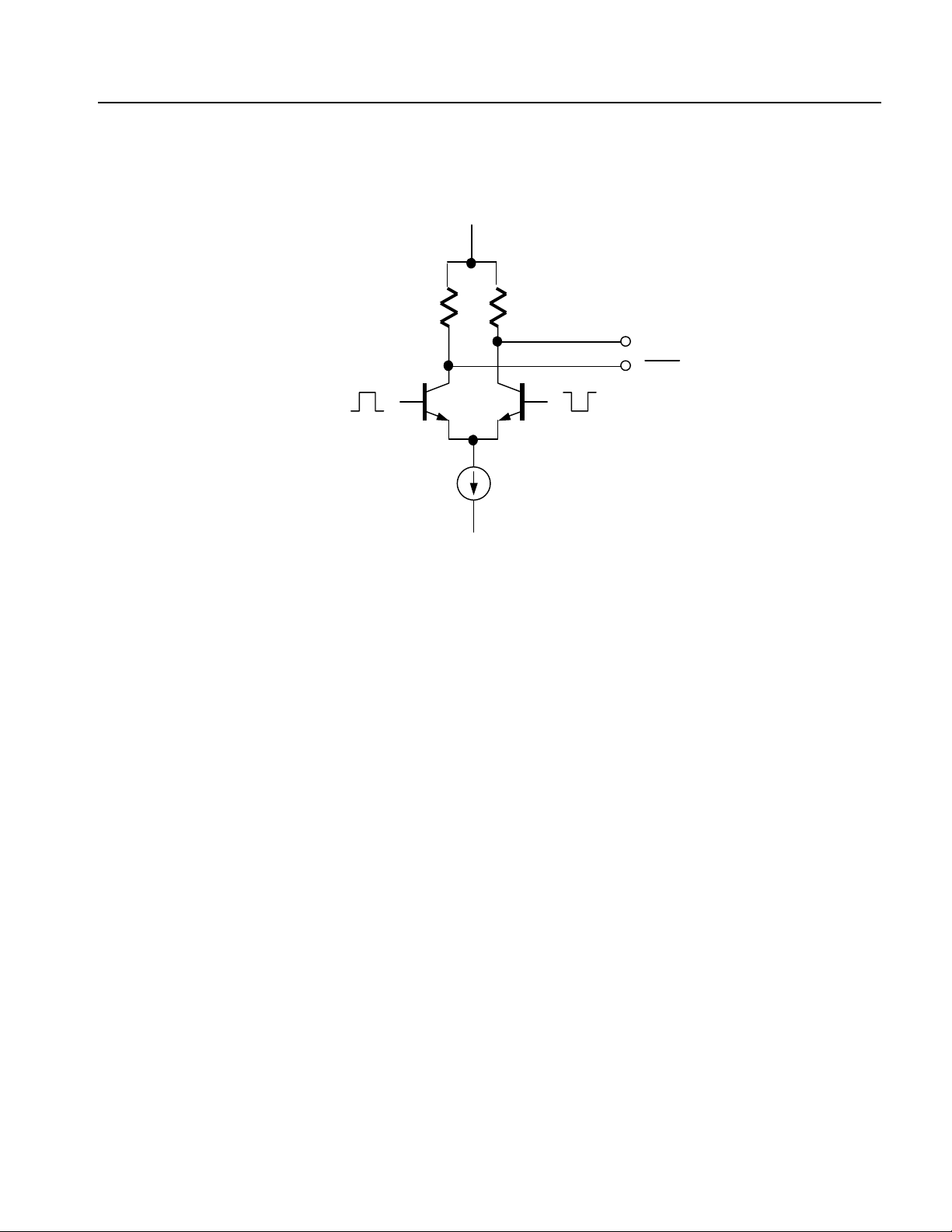
Figure 1-9: Output part equivalent circuit of MARKE
Marker output
AWG615 Service Manual 1-19

Specifications
Table 1-14: Event Input
Characteristics Description
Connector 9–pin, D type on the rear panel
Number of events 7 bits
Input signal 7 event bits and Strobe
Threshold TTL level
Maximum input 0 V to + 5 V (DC + peak AC)
Impedance 1 kΩ, pull–up to +3.3 V
Enhanced mode
Minimum pulse width 320 clocks + 10 ns
Event hold off time (The time interval between the last event input point and the next acceptable event input point)
≤ 896 clocks + 20 ns
Delay to analog out, Typical
(Jump timing: ASYNC) (Output: Norm, Filter: Through)
Strobe: On 1691.5 clocks + 10 ns
Strobe: Off 1947.5 clocks + 6 ns
Event input to strobe input
Setup time 192 clocks + 10 ns
Hold time 192 clocks + 10 ns
Table 1-15: 10 MHz reference clock input
Characteristics Description
Input voltage range 0.2 V
to 3.0 V
p–p
(into a 50 Ω load, AC coupling)
p–p
Maximum ±10 V
Impedance 50 Ω, AC coupling
Frequency range 10 MHz ±0.1 MHz
Connector Rear panel BNC connector
Table 1-16: External clock input
Characteristics Description
Connector Rear panel SMA connector
Impedance 50 Ω, AC coupling
Required input voltage range swing 0.4 V
p–p
to 2 V
into a 50 Ω load
p-p
Required duty cycle 50 ±5 %
1-20 AWG615 Service Manual

Table 1-16: External clock input
Characteristics Description
Frequency range 125 MHz to 2.7 GHz
Note: Slew rate should be more than 10 mV/ns.
Table 1-17: C input
Characteristics Description
This signal is used for only Synchronous operation between Master and Slave unit.
Connector
Input signal type Complementary
Rear panel SMA connector
Table 1-18: T input
Specifications
Characteristics Description
This signal is used for only Synchronous operation between Master and Slave unit.
Connector
Input signal type Complementary
Rear panel SMA connect
AWG615 Service Manual 1-21

Specifications
Table 1-19: Function Generator (FG)
Characteristics Description
Operation Mode Continuous mode only
Waveform Shape Sine, Triangle, Square, Ramp, Pulse, DC
Frequency 1.000 Hz to 270.0 MHz
Amplitude
Range 0.020 V
( OPTION02 : 0.5 V
Resolution 1 mV
Offset (except option 02)
Range -0.500 V to +0.500 V, into a 50 Ω load
Resolution 1 mV
DC Level (except option 02) DC waveform only
Range -0.500 V to +0.500 V, into a 50 Ω load
Resolution 1 mV
Polarity Normal, Inverted
Duty
Range 0.1 % to 99.9 %
Resolution Frequency Resolution
1.000 Hz to 4.000 MHz 0.1 %
4.001 MHz to 20.00 MHz 0.5 %
20.01 MHz to 40.00 MHz 1.0 %
40.01 MHz to 80.00 MHz 2.0 %
80.01 MHz to 100.0 MHz 2.5 %
100.1 MHz to 160.0 MHz 4.0 %
160.1 MHz to 200.0 MHz 5.0 %
200.1 MHz to 270.0 MHz 10.0 %
Marker Out
Pulse Width
Mrker1 Hi : 0 % to 20 % of 1 waveform period
Lo : 20% to 100 % of 1 waveform period
Marker2 Hi : 0 % to 50 % of 1 waveform period
Lo : 50 % to 100 % of 1 waveform period
to 2.000 V
p–p
, into a 50 Ω load
p–p
to 1.0 V
p–p
, into a 50 Ω load )
p–p
Hi : 0 % to 52 % of 1 waveform period
Lo : 52 % to 100 % of 1 waveform period at frequency range is 100.1MHz to 160.0MHz
Level
Hi 1.0 V min into a 50 Ω load
Lo 0 V max into a 50 Ω load
1-22 AWG615 Service Manual

Table 1-20: Display
Characteristics Description
Display
Size 16 cm (6.4 in.) diag. LCD
Display area Horizontal: 130.6 mm (5.14 in)
Vertical: 97.0 mm (3.81 in)
Resolution 640 (H) × 480 (V) pixels
Table 1-21: AC line power
Characteristics Description
Rating voltage 100 VAC to 240 VAC, CAT II
Voltage range 90 VAC to 250 VAC
Frequency range 48 Hz to 63 Hz
Maximum consumption 240 VA
Maximum current 5 A
Fuse rating 10 A fast, 250 V, UL 198G (3 AG)
5 A (T), 250 V, IEC 127
Specifications
Tabl e 1- 22 : T ime r
Characteristics Description
Timer
6 yearsOperation time
Type Li 3 V, 190 mAh
Table 1-23: Interface connectors
Characteristics Description
GPIB 24–pin, IEEE 488.1 connector on the rear panel
Ethernet 100/10 BASE–T, RJ–45 connector on the rear panel
Keyboard connector 6–pin, mini–DIN connector on the rear panel
AWG615 Service Manual 1-23

Specifications
Table 1-24: Installation requirement
Characteristics Description
Heat dissipation
Maximum power 220 W max. (maximum line current: 3 A
Surge current
Cooling clearance
30 A (25 ° C) peak for equal to or less than 5 line cycles,
after the instrument has been turned off for at least 30s
To p ,
Bottom
Sides 15 cm (6 in)
Rear 7.5 cm (3 in)
2 cm (0.8 in)
2 cm (0.8 in)
NOTE: The feet on the bottom provide the required clearance when set on a
flat surface.
, at 50 Hz)
rms
Table 1-25: Maintenance requirement
Characteristics Description
Calibration
The instrument should be fully calibrated at least every 12 months.
Table 1-26: Environmental
Characteristics Description
Atmospherics
Temperature
Operating +10 ° C to +40 ° C
Non-operating -20 ° C to +60 ° C
Relative humidity
Operating 20 % to 80 % (no condensation)
Maximum wet–bulb temperature 29.4 °C
Non-operating 5 % to 90 % (no condensation)
Maximum wet–bulb temperature 40.0 °C
Altitude (Hard disk drive restriction)
Operating Up to 3 km (10 000 ft)
Maximum operating temperature decreases 1 °C each 300 m (1 000 ft) above 1.5 km (5 000
ft)
Non-operating Up to 12 km (40 000 ft)
1-24 AWG615 Service Manual

Table 1-26: Environmental
Dynamics
Random vibration
Operating 2.646 m/s
Non-operating 22.344 m/s
2
rms (0.27Grms), from 5 Hz to 500 Hz, 10 minutes
2
rms (2.28Grms), from 5 Hz to 500 Hz, 10 minutes
Shock
Non-operating 294 m/s
2
(30 G), half–sine, 11 ms duration
Table 1-27: Mechanical
Characteristics Description
Net weight (without package) 14.1 kg (31.1 lb)
Dimensions (without package) Height 177 mm (6.97 in)
193 mm (7.60 in) with Feet
Width 422 mm (16.61 in)
433 mm (17.05 in) with Handle
Length 470 mm (18.50 in)
508 mm (20.00 in) with Rear Feet
Net weight (with package) 24.5 kg (54.0 lb)
Dimensions (with package) Height 400 mm (15.75 in)
Width 550 mm (21.65 in)
Specifications
Length 700 mm (27.56 in)
177
193
424
433
470
508
Figure 1-10: Dimensions
AWG615 Service Manual 1-25

Specifications
Certification and Compliances
The certification and compliances for the AWG615 Arbitrary Waveform Generator
are listed in Table 1-28.
Table 1-28: Certifications and compliances
Characteristics Description
EC declaration of conformity
EC council EMC Directive 89/336/EEC, amended by 89/336/EEC; EN61326-1: 1997 Product
Family Standard for Electrical Equipment for Measurement, Control, and Laboratory
Use-EMC Requirements.
Emissions:
EN 55011 Class A
EN 61000 - 3 - 2
EN 61000 - 3 - 3
Immunity:
EN50082 -1
EN 61000 - 4 - 2
EN 61000 - 4 - 3
EN 61000 - 4 - 5
EN 61000 - 4 - 6
Radiated and Conducted emissions
Power Line Harmonic
Line voltage alteration and flicker
Electrostatic Discharge Immunity
Radiated RF Electromagnetic Field Immunity
Surge Immunity
Conducted Disturbances Induced by RF Field Immunity
EN 61000 - 4 - 4
EN 61000 - 4 - 8
EN 61000 - 4 - 11
Compliance was demonstrated to the following specification as listed in the Official Journal of
the European Communities:
Low Voltage Directive 73/23/EEC, amended by 93/68/EEC
EN 61010 -1 Safety requirements for electrical equipment for measurement,
Australia/New Zealand declaration of
conformity - EMC
Safety UL3111–1 - Standard for electrical measuring and test equipment
Third party certification
Self declaration IEC 61010 -1:2001 - Safety requirements for electrical equipment for measurement, control,
Installation category
Conforms with the following standards in accordance with the Electromagnetic Compatibility
Framework:
AS/NZS 2064.1/2
Class A radiated and Conducted Emissions
CAN/CSA C22.2 No. 1010.1 - Safety requirements for electrical equipment for measurement,
control and laboratory use
and laboratory use
Power input — Installation Category II (as defined in IEC 61010–1, Annex J)
6
Electrical Fast Transient/Burst Immunity
Power Frequency Electromagnetic
Power Line Interruption Immunity
control, and laboratory use
1-26 AWG615 Service Manual

Table 1-28: Certifications and compliances
Characteristics Description
Pollution degree
6
Up to 200 mV
noise is allowed on the output during this test.
p–p
Pollution Degree 2 (as defined in IEC 61010–1)
Table 1-29: Installation category and Pollution degree Descriptions
Characteristics Description
Installation category
Pollution degree
Terminals on this product may have different installation category designations. The
installation categories are:
Category Descriptions
CAT IIIe Distribution–level mains (usually permanently connected).
Equipment at this level is typically in a fixed industrial location
CAT II Local–level mains (wall sockets). Equipment at this level
includes appliances, portable tools, and similar products.
Equipment is usually cord–connected
CAT I Secondary (signal level) or battery operated circuits of
electronic equipment
A measure of the contaminates that could occur in the environment around and within a
product. Typically the internal environment inside a product is considered to be the same as
the external. Products should be used only in the environment for which they are rated.
Specifications
Category Descriptions
Pollution Degree 1 No pollution or only dry, nonconductive pollution occurs.
Products in this category are generally encapsulated,
hermetically sealed, or located in clean rooms.
Pollution Degree 2 Normally only dry, nonconductive pollution occurs.
Occasionally a temporary conductivity that is caused by
condensation must be expected. This location is a typical
office/home environment. Temporary condensation occurs only
when the product is out of service.
Pollution Degree 3 Conductive pollution, or dry, nonconductive pollution that
becomes conductive due to condensation. These are sheltered
locations where neither temperature nor humidity is controlled.
The area is protected from direct sunshine, rain, or direct wind.
Pollution Degree 4 Pollution that generates persistent conductivity through
conductive dust, rain, or snow. Typical outdoor locations.
AWG615 Service Manual 1-27

Specifications
1-28 AWG615 Service Manual

Operating Information


Preparation for Use
This subsection provides the following information:
Supplying Operating Power
Operating Environment
Installation
Repackaging Instructions
Supplying Operating Power
WAR N I NG. To avoid equipment failure and potential fire or personal shock
hazards, do not exceed the maximum rated operating voltage of 250 V between the
voltage–to–ground (earth) and either pole of the power source. The AWG615
Arbitrary Waveform Generator operates from a single–phase power source and
has a three–wire power cord with a two–pole, three–terminal grounding plug.
Also, before making a connection to the power source, be sure the AWG615
Arbitrary Waveform Generator has a suitable two–pole, three–terminal
grounding–type plug.
To avoid personal shock, do not touch any conductive parts. All accessible
conductive parts are directly connected through the grounding conductor of the
power cord to the grounded (earth) contact of the power plug. The AWG615
Arbitrary Waveform Generator is safety Class 1 equipment (IEC designation).
To prevent electrical shock, remove all power from the instrument, turn the
PRINCIPAL POWER SWITCH on the back panel to OFF, and disconnect the
power cord from the instrument. Some components in the AWG615 Arbitrary
Waveform Generator are still connected to line voltage after toggling the
instrument to Standby from the front panel ON/STBY button.
Power Cord Information
AWG615 Service Manual 2-1
A power cord with the appropriate plug configuration is supplied with each
AWG615 Arbitrary Waveform Generator. Table 2-1 provides color–coding
identification for the power cord conductors. If you require a power cord other than
the one supplied, refer to Table 2-2.

Preparation for Use
Table 2-1: Power–cord conductor identification
Conductor Color Alternate Color
Ungrounded (Line) Brown Black
Grounded (Neutral) Light Blue White
Grounded (Earthing) Green/Yellow Green
Table 2-2: Power cord identification
Plug configuration Normal usage Option number
North America
125 V
A0
Europe
230 V
United Kingdom
230 V
Australia
230 V
Switzerland
230 V
Japan
100 V
A1
A2
A3
A5
A6
China
230 V
No power cord supplied. A99
A10
2-2 AWG615 Service Manual

Preparation for Use
Operating Voltage
Memory Backup Power
Operating Environment
Operating Temperature
The AWG615 Arbitrary Waveform Generator operates with any line voltage from
90 to 250 VAC
either of which may be used throughout the line voltage and frequency ranges. The
two fuses are not interchangeable as each requires a different fuse cap.
Memory modules with on–board batteries allow the AWG615 Arbitrary
Waveform Generator to retain only internal clock data upon loss of the AC power
source.
To set the date and time in the waveform generator, see the Reference:Internal
Clock (Date and Time) section of the AWG615 Arbitrary Waveform Generator
user manual.
The following environmental requirements are provided to ensure proper operation
and long instrument life.
Operate the Waveform Generator where the ambient air temperature ranges from
10° C to +40° C (50° F to +104° F). Store the Waveform Generator at ambient
temperatures from -20° C to +60° C (-4° F to +140° F). After storage at
temperatures outside the operating limits, allow the chassis to stabilize to a safe
operating temperature before applying power.
with any line frequency from 48 to 63 Hz. There are two fuses,
RMS
Ventilation Requirements
The Waveform Generator is cooled by air drawn in and then exhausted through the
cabinet side panels by an internal fan. To ensure proper cooling of the Waveform
Generator, allow at least 15 cm (6 in) clearance on both sides, 2.0 cm (0.8 in) on
the top and bottom, and 7.5 cm (3 in) at the rear of the Waveform Generator. (The
feet on the bottom of the Waveform Generator provide the required clearance when
set on flat surfaces.)
CAUTION. When the air flow is restricted and the temperature of the DAC module
°
surface exceeds 80
temporarily shut down to protect the internal modules. To prevent temporary
shutdown of the waveform generator, do not restrict air flow through the chassis.
The
AWG615 Arbitrary Waveform Generator displays the message “Power fail or out
of temperature limit” before shutting down.
If the
AWG615 Arbitrary Waveform Generator shuts down unexpectedly, create more
ventilation around the waveform generator. Wait a few minutes to allow cool down
and then switch the power on again.
C, the AWG615 Arbitrary Waveform Generator may
AWG615 Service Manual 2-3

Preparation for Use
Installation
Before installation, refer to the Safety Summary section at the front of this manual
for power source, grounding, and other safety information.
Environment
Verify that you have the correct operating environment.
CAUTION. Damage to the instrument can occur if it is powered on at temperatures
outside the specified temperature range.
The AWG615 Arbitrary Waveform Generator operates correctly in ambient
temperatures from +10° C to +40° C (50° F to +104° F) and relative humidity from
20% to 80% with no condensation. If the instrument is stored at temperatures
outside this range, do not switch on the power until the chassis is within the
operating temperature range. For detailed operating environment information,
refer to Specifications on page 1-3, 1-24 and 2-3.
NOTE. If you are installing the instrument in a rack, refer to the instruction sheet
that accompanies the rack–mounting kit for proper installation procedures.
Verify that there is nothing blocking the flow of air at the fan and air intake holes.
The instrument exhausts air using the internal fan. Create open space at the sides
of the instrument so that it does not overheat. The following are the minimum space
requirements for air flow around the instrument:
Rear 7.5 cm (3 in)
Left and right 15.0 cm (6 in)
Top and bottom 2 cm (0.8 in)
(The feet on the bottom of the instrument provide the required clearance when
set on a flat surface.)
2-4 AWG615 Service Manual
Preparation for Use
NOTE. If the air flow is restricted and the internal temperature of the AWG615
Arbitrary Waveform Generator exceeds the proper operating temperature range,
the instrument temporarily shuts down to protect the internal modules from
overheating. To prevent temporary shutdown of the AWG615 Arbitrary Waveform
Generator do not restrict air flow through the chassis.
If the AWG615 Arbitrary Waveform Generator shuts down unexpectedly, improve
the ventilation around the waveform generator and wait a few minutes to allow it
to cool down; then switch the power on again.
You cannot power on the instrument when the ambient temperature exceeds the
instrument temperature operation range. Wait until the instrument cools down, or
the ambient temperature decreases to valid operating temperatures, before turning
on the instrument again.
Check Fuse
Verify that the fuse is the proper type and rating.
Remove the fuse from the fuse holder on the rear panel and check the fuse. To
remove the fuse, turn it counterclockwise with a screwdriver while pressing in.
Table 2-3 lists the two fuse types and ratings.
WAR N I NG. To avoid electrical shock, be sure that the power cord is disconnected
from the socket before checking the line fuse.
Table 2-3: Fuse part numbers
Fuse Fuse part number
Fuse, cartridge, 3AG, 10A, 250 VAC, FAST, 6.35 mm x 31.75 mm
(0.25 in × 1.25 in)
Fuse, cartridge, DIN 5 x 20 mm, 5A, 250 V Slow Blow,
5 mm x 20 mm (0.197 in x 0.788 in) (IEC 127)
NOTE. The second fuse listed in the table above is approved under the IEC
159–0407–XX
159–0210–XX
standards. This fuse is used in equipment sold in the European market.
Table 2-4: Fuse cap part numbers
Fuse cap Fuse cap part number
Cap, fuseholder, 3AG fuses 200–2264–XX
Cap, fuseholder, 5x20 mm fuses 200–2265–XX
NOTE. The second fuse listed in the table on page 2-5 is approved under the IEC
standards. This fuse is used in equipment sold in the European market.
AWG615 Service Manual 2-5

Preparation for Use
Check Voltage Settings
Connect Power Cord
Standby Power
Check that you have the proper electrical connections. The AWG615 Arbitrary
Waveform Generator operates within the following power supply voltage and
frequency ranges:
Line voltage range
Line frequency
Maximum power
100 - 240 V
48 - 63 Hz
240 VA
Connect the proper power cord from the rear panel power connector to the power
system.
NOTE. The AWG615 Arbitrary Waveform Generator is shipped with a 115 V
power cord. If the AWG615 Arbitrary Waveform Generator is to be used with
230 V power, the power cord must be replaced with one appropriate for the power
source used. See Table 2-2 for the available power cord types.
Push the PRINCIPAL POWER SWITCH (shown in Figure 2-1) on the rear panel
of the instrument. Power is now applied to the instrument standby circuitry. Once
the instrument is installed, leave the PRINCIPAL POWER SWITCH on and use
the ON/STBY switch, located on the front panel, to toggle the instrument between
ON and STBY.
PRINCIPAL POWER SWITCH
Fuse
Power connector
Figure 2-1: Rear panel power switch, fuse holder, and power connector
2-6 AWG615 Service Manual
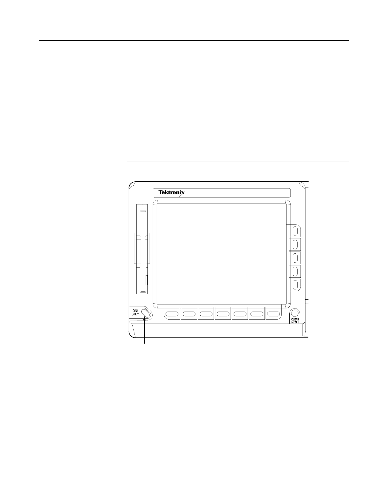
Preparation for Use
Power On
To power on the instrument, push the ON/STBY switch (shown in Figure 2-2) on
the lower left side of the front panel. Check that the fan is blowing air out of the
instrument.
NOTE. The instrument must be warmed up for at least 20 minutes and the clock
calibrated to operate at its optimum accuracy.
It will take 1 - several minutes to start up after pushing the ON/STBY switch. The
starting time depends on the data length of the waveform file loaded when power
0ff was executed last time.
In addition, AWG cannot start up when floppy disk other than a system disk is
inserted in the floppy disk drive. Please power on after ejecting a disk.
AWG615
ARBITRARY WAVEFORM GENERATOR 2.7 GS/s
ON/STBY switch
Figure 2-2: Location of the ON/STBY switch
AWG615 Service Manual 2-7

Preparation for Use
Power-On Diagnostics
Power Off
The instrument automatically runs power–on self tests to check that the instrument
is operating normally.
Check the results of the power–on self tests. If all the diagnostic tests are completed
without error, the instrument displays Pas s and then the SETUP menu screen.
If the system detects an error, the instrument displays Fai l and the error code
number on the screen. You can still operate the instrument if you exit this state, but
the wave output accuracy is not guaranteed until the error is corrected. To exit the
diagnosis mode, push any button. The system goes to the SETUP menu screen.
NOTE. Contact your local Tektronix Field Office or representative if the
instrument displays an error message. Make sure to record the error code number.
Power off the AWG615 Arbitrary Waveform Generator by toggling the ON/STBY
switch to the STBY position and turning the PRINCIPAL POWER SWITCH on
the rear panel to OFF.
WAR N I NG. To prevent electrical shock, remove all power from the instrument,
turn the PRINCIPAL POWER SWITCH on the back panel to OFF, and
disconnect the power cord from the instrument. Some components in the AWG615
Arbitrary Waveform Generator are still connected to line voltage after turning off
the instrument from the front panel ON/STBY button.
To prevent loss of data and/or damage to the hard disk, before the power off,
confirm that the hard disk LED on the lower right of the front panel does not light
or blink.
2-8 AWG615 Service Manual

Repackaging for Shipment
Use the original packaging material to return the instrument. If the original
packaging is unfit for use or is not available, repackage the instrument as follows:
1. Obtain a corrugated cardboard shipping carton with dimensions of at least
2. If you are shipping the instrument to a Tektronix Service Center for repair or
Preparation for Use
three inches greater than the instrument dimensions and having a carton test
strength of at least 125 kg (275 lb).
calibration, attach a tag to the instrument with the following information:
Owner of the instrument (with address)
Name of a person at your firm who may be contacted if additional
information is needed
Complete instrument type and serial number
A description of the service required
3. Wrap the instrument with polyethylene sheeting or equivalent to protect the
outside finish and prevent entry of packing materials into the instrument.
4. Cushion the instrument on all sides by tightly packing urethane foam between
the carton and the instrument, allowing for 7.62 cm (3 in) of padding on each
side (including top and bottom).
5. Seal the carton with shipping tape or with an industrial stapler.
6. Make sure that the Tektronix Service Center address and your return address
are placed on the carton in one or more prominent locations.
NOTE. To avoid damaging the instrument, do not ship it with a diskette inside the
floppy disk drive. When a diskette is inside the drive, the disk release button
protrudes and makes the button susceptible to damage.
AWG615 Service Manual 2-9

Preparation for Use
Applying and Interrupting Power
Refer to the following information when you power on or power off the instrument,
or when power is interrupted due to an external power failure.
Power On
Power Off
Upon power on, the Waveform Generator runs a power–on self check. If it passes,
the AWG615 Arbitrary Waveform Generator displays a Pas s status message and a
prompt to press any key to continue. If this fails, the AWG615 Arbitrary Waveform
Generator displays a diagnostic log that identifies the area(s) that failed and a
prompt to press any key to continue. Refer to the Maintenance section for
information on diagnostics and fault isolation.
CAUTION. DO NOT power off the Waveform Generator when either running a
signal path compensation or when doing any of the adjustments described in the
Adjustment Procedures section. To do so might result in the loss of internally stored
adjustment constants.
Do not power off the instrument when doing operations that affect the data stored
in the memory. Wait for the instrument to finish the operation when doing
adjustments, saving waveforms, or saving setups.
Improper power off, toggling the instrument to STBY improperly, or unexpected
loss of power to the AWG615 Arbitrary Waveform Generator can result in
calibration data corruptions on the hard disk.
2-10 AWG615 Service Manual

Operating Basics
This section provides the following information:
The Controls and Connectors subsection describes the instrument buttons,
The Menu Operations subsection describes how to operate menus and enter
The File Management subsection describes the overview of the instrument
The Editor Overview subsection introduces the waveform editor functions and
The Setup Overview subsection describes the SETUP screen, and simple
The Theory of Operation subsection describes the electrical operation of the
Controls and Connectors
controls, connectors, and typical screen displays.
numeric and text values.
commands and operations for file management tasks.
operations.
operations.
AWG615 Arbitrary Waveform Generator
Front Panel
Figures 2-1, 2-2, and 2-3 show the locations of the front–panel controls and
connectors.
CAUTION. To prevent data corruption, do not push the eject button while the LED
is on. Doing so can cause data corruption on the floppy disk and cause the
instrument to hang up. If this happens, turn power off then back on again.
To prevent damage to the instrument, do not apply any external voltage to the
output connector or marker connector.
AWG615 Service Manual 2-11

Operating Basics
SETUP menu button
Displays the SETUP Main Menu for
setting the waveform output parameters.
EDIT menu button
Displays the EDIT Main Menu for
creating or editing waveforms, as well as
performing directory and file tasks.
Floppy disk drive
Save or load the various types of data
created or used in the instrument to/from
the 3.5 inch 2HD floppy disk with
MS-DOS format. You can also format a
floppy disk with this instrument.
AWG615
ARBITRARY WAVEFORM GENERATOR 2.7GS/s
Bottom and side
bezel menu buttons
The bottom buttons call up
submenus, and the side buttons
execute more detailed operations
within the submenus.
APPL menu button
Displays the APPL Main Menu for running
a specific application program to create
waveforms.
UTILITY menu button
Displays the UTILITY Main Menu for
setting the instrument parameters.
Arrow buttons
Controls up, down, right, and left
movements of the cursor or a selected item;
for example, movements of a selected item
in a dialog box or pop-up menu.
See Figure 2-3
HARDCOPY button
Produces a hardcopy of the screen display,
which can be transferred, as a file, to the hard
disk, a floppy disk, and/or a networked
device.
See Figure 2-2
ON/STBY button
This button is the power
switch in normal
operation. The
PRINCIPAL POWER
SWITCH on the rear
panel must be on.
CLEAR MENU button
Cancels the current
operation and closes
side and submenus.
The display can be
returned to the top level
by pushing this button
repeatedly.
CAUTION
To prevent loss of data and/or damage to the hard
drive, before the power off, be sure to confirm the
floppy disk or hard drive LED is not on or blinking.
CAUTION
To prevent damage to the instrument, do not apply the
voltage to OUTPUT or MARKER connectors.
Output connectors
Provides normal (CH1) and inverted
(CH1) waveforms.
The maximum output level is 2 V
into a 50 Ω load in Normal mode,
and 1 V
mode and option02. If you use only
one output connector, you must
terminate the other connector using
a 50 Ω termination.
into a 50 Ω load in Direct
p-p
MARKER OUT connectors
Outputs marker signals. Each channel is
equipped with two MARKER OUT connectors.
If you use only one output connector for each
p-p
marker, you must terminate the other
connector using a SMA termination.
PANEL LOCK LED indicator
The LED indicator is on when the front panel
control is locked. You can lock the front panel
controls only through GPIB interface.
HDD LED indicator
The LED indicator is on when the disk drive is in operation.
Figure 2-1: Front panel controls
2-12 AWG615 Service Manual

Operating Basics
TOGGLE button
Switches the active cursor on the waveform and pattern
editor. In the sequence editor, this button can be used to
cancel the numeric input mode and make the left and right
arrows available to move the highlight cursor.
SHIFT button
When you push a numeric or unit button while the
SHIFT LED is on, the function shown in blue above
a key is executed. The SHIFT button toggles on
and off. When the instrument displays the File
Name Input dialog box, you can input upper case
characters when the SHIFT LED is on. When you
exit the dialog box, the SHIFT LED also goes off.
This ENTER key has the same
function as that found in keypad.
CLR button
Clears text in an active text field.
Delete button
Deletes a character positioned just left of the text cursor and
moves the cursor to the left by one character. This button does
not function when the text cursor is at the left-most position.
ENTER key
General Purpose knob
Selects a menu item or adjusts a numeric value on the instrument. When
the knob icon is displayed on the screen next to an item, it indicates that
that item can be controlled with the general purpose knob.
Keyp ad
Enters numeric values. The keys G, M, k, m, µ, n
and p are unit keys. The keys A, B, C, D, E and F
are used to enter a hexadecimal value. These keys
are accessed with the SHIFT button. The unit keys
also work like the ENTER key.
Confirms the numeric or character string you typed and enters it
in the instrument. When using the general purpose knob, push
ENTER to confirm the settings.
INF button
Sets the Repeat Count to Inf. in the sequence editor. This button
can be used only for this purpose.
Figure 2-2: Front panel keypad area
AWG615 Service Manual 2-13

Operating Basics
RUN button
Enables waveform output. The signal
output depends on the RUN mode
settings.
QUICK EDIT button
Enters the QUICK EDIT mode from the waveform editor. This button
allows you to edit waveforms that have immediate effect on the output
signal. Use together with the VERTICAL and HORIZONTAL controls for
quick edit.
TRIGGER controls
Controls the trigger parameters.
Pushing the TRIGGER MENU button
displays the Trigger side menu. This
has the same effect as pushing
SETUP (front)→Tr ig g er (bottom).
The LEVEL knob adjusts the trigger
level.
FORCE TRIGGER button
Pushing the FORCE TRIGGER button
generates an internal trigger event.
VERTICAL controls
Used to control the output vertical axis parameters.
Pushing the VERTICAL MENU button displays the VERTICAL side menu.
This is the same as selecting SETUP (front)→Vertical (bottom).
The OFFSET knob, adjusts the vertical offset.
The LEVEL/SCALE knob adjusts the amplitude.
Figure 2-3: Front panel trigger and output controls
Rear Panel
Figure 2-4 show the rear panel signal and power connectors.
CAUTION. To prevent damage to the instrument, only apply signals within the
stipulated range to the INPUT connector.
Do not apply any external voltage to the OUTPUT connector.
FORCE EVENT button
Pushing the FORCE EVENT button generates an
internal event signal.
HORIZONTAL controls
Used to control the output horizontal axis parameters.
Pushing the HORIZONTAL MENU button displays the Horizontal side menu.
This is the same as selecting SETUP (front)→Horizontal (bottom).
The OFFSET knob adjusts the horizontal position.
The SAMPLE RATE/SCALE knob adjusts the clock frequency.
2-14 AWG615 Service Manual

Operating Basics
TRIG IN connector
External trigger signal
input.
10 MHz REF IN connector
External 10 MHz reference
clock signal input.
10 MHz REF OUT connector
The internal 10 MHz clock reference signal is output when the
internal clock reference is selected. The external clock reference
signal is output when the external clock reference is selected.
The maximum output level is 1.2 V
EVENT IN connector
Inputs external event signals. This
signal can be used for sequence
control in Enhanced mode
into 50 Ω load
p-p
DISPLAY MONITOR OUT
connector
Connect to an external monitor.
AWG615
AWG615
100/10BASE-T connector
Connect to the Ethernet
network.
KEYBOARD connector
Connect to a standard PC
101-key keyboard.
IEEE STD 488 connector
A GPIB connector for remote
computer control through an
IEEE 488 standard parallel interface.
PRINCIPAL POWER SWITCH
Applies power to the standby circuit. In
addition to this switch being on, the front
panel ON/STBY switch must also be
turned on.
Power supply fuse holder
The 10 A fast blow and 5 A (T)
fuse are used for 115 V and
230 V systems, respectively
MASTER/SLAVE CONNECTION
These C (clock) and T (trigger) signals are used for only Synchronous
operation between Master unit and Slave unit.
The C OUT n clock signals supplied by Master are inputted into C IN
of Master and Slave.
Similarly, the T OUT n trigger signals supplied by Master are inputted
into T IN of Master and Slave.
VCO OUT connector
Sampling clock signal output.
The maximum output level is
0.4 V
into 50 Ω load
p-p
EXT CLOCK IN connector
External clock signal input.
An acceptable external clock
signal is
0.4 to 2.0 V
50±5 % duty cycle, and
125 MHz to 4.2 GHz frequency
range.
input voltage,
p-p
Power connector
Connect the provided power
cable to this connector.
Figure 2-4: Rear panel signal and power connectors
AWG615 Service Manual 2-15

Operating Basics
Menu Operations
This section describes the AWG615 Arbitrary Waveform Generator menu system
and numeric and text input methods.
Menu System
The AWG615 Arbitrary Waveform Generator uses menus to make selections.
There are four menu buttons, labeled EDIT, SETUP, APPL, and UTILITY, as
shown in Figure 2-5. Pushing a menu button displays the corresponding screen and
menu buttons. These menus let you edit waveforms, initialize instrument settings,
define instrument operation, and specify waveform output parameters.
You select items within the displayed menu by pushing the bottom or side bezel
button nearest to the menu item. These buttons consist of seven bottom buttons and
five side buttons, as shown in Figure 2-5. These menu bezel buttons are referred to
as bottom menu buttons (or bottom buttons) and side menu buttons (or side
buttons).
The CLEAR MENU button cancels the current menu operation, clears the current
menus from the screen, and exits to the previous instrument state.
Menu buttons
AWG615
ARBITRARY WAVEFORM GENERATOR 2.7 GS/s
Side menu bezel buttons
Bottom menu bezel buttons
(bottom buttons)
(side buttons)
CLEAR MENU button
Figure 2-5: Menu buttons, bezel menu buttons, and the CLEAR MENU button
2-16 AWG615 Service Manual

Operating Basics
Menu Elements
Pushing a front–panel menu button displays the screen and bottom menu items
associated with the button. You select a bottom menu item by pushing the button
directly below that menu item.
Pushing a bottom button displays a side menu, pop–up menu, list, or dialog box.
Figures 2-6 through 2-8 show examples of the side menu, pop–up menu and dialog
box, respectively.
Status display
Side menu
Bottom menu
Figure 2-6: Bottom and side menus
You use a side menu button to display a side submenu, set a parameter, perform a
task, or cancel an operation. Table 2-1 describes the side menu button types.
AWG615 Service Manual 2-17

Operating Basics
Table 2-1: Side menu elements
Menu items Description Menu items Description
Executes the displayed function
immediately.
Switches between two
parameters each time the side
button is pushed.
Allows entering numeric values
using the numeric buttons or the
general purpose knob.
Cannot be used in the current
instrument state (menu item is
grayed out).
Allows making selections by
using the general purpose
knob.
Displays submenus. Note that
the label on the item is followed
by an ellipsis (...).
The pop–up menu example, shown in Figure 2-7, displays a list of choices from
which you make a selection. Use the general purpose knob or the front–panel arrow
buttons to move up or down in the list. Push the OK side button or the ENTER
front–panel button to confirm the selected item.
Figure 2-7: Pop–up menu example
2-18 AWG615 Service Manual

Operating Basics
The dialog box example, shown in Figure 2-8, displays a form in which you make
selections or enter values. Use the front–panel arrow buttons to select items or
fields. A selected field or item is highlighted. Use the keypad buttons or the general
purpose knob to change values in selected text/numeric fields or change 1–of–N
fields. A 1–of–N field contains two or more choices of which only one can be
selected at a time.
Push the OK side button to confirm the dialog box. Push the Cancel side button or
the CLEAR MENU button to exit the dialog box without making any changes.
Text/Numeric fields
1-of-N choice
Figure 2-8: Dialog box example
Refer to Numeric Input on page 2-20 and Text Input on page 2-22 for more
information on selecting and entering values in menus and dialog boxes.
AWG615 Service Manual 2-19

Operating Basics
Numeric Input
You can enter numeric values by using either the numeric keypad or the general
purpose knob. If the side menu item displays a value, you can alter this value using
the general purpose knob or numeric buttons.
Pushing the type of side menu button or selecting a parameter in a pop–up menu
causes the current setting to appear on the right end of the Status Display area as
shown in Figure 2-9.
Knob icon
Underscore
The General Purpose Knob
The Numeric Keypad
Figure 2-9: Knob icon displayed in Status Display area
A knob icon with a numeric value that includes an underscore character indicates
that you can change the value at the underscore location by using the general
purpose knob or keypad buttons. By default, the underscore character is positioned
under the digit specified depending on the parameters. You can only change the
value represented by the digits at and to the left of the underscore. Use the a and '
arrow buttons to move the underscore to the desired position, and then turn the
general purpose knob to change the value.
If the numeric value has the knob icon, but does not have the underscore, then
turning the general purpose knob cycles through a predefined set of values.
When using the general purpose knob, values you change in side menus and menu
screens take effect immediately. Values in pop–up menus are not effective until
you push the OK side button or the ENTER front–panel button.
Figure 2-10 shows the numeric keypad, with descriptions of the button operations.
2-20 AWG615 Service Manual

The SHIFT button enters a character
labeled in blue. Push the SHIFT button
and then push the keypad button.
Operating Basics
The CLR button
deletes all characters
in the current field.
The DELETE button deletes the
character to the left of the caret.
The ENTER button
enters the current value
into the instrument.
Figure 2-10: Keypad buttons
The G, M, k, m, µ, n, and p are unit buttons. The A, B, C, D, E, and F buttons are
used for entering hexadecimal values.
To use the numeric keypad to enter a value, position the caret to where you want
to change a value, and then push a keypad button. If you want to enter a unit value
labeled in blue just above each numeric button, push or hold down the SHIFT
button, and then push the corresponding numeric button.
To enter or change more than one character, move the caret to the next position to
change. When you are done entering values, push the ENTER button to confirm
the changes and enter them into the instrument. For example, to enter 200.5 µs,
push 2, 0, 0, ., 5, SHIFT and 4 (µ) buttons in this order.
When you enter a value larger than the maximum value in the range for the
parameter, the parameter will be set to the maximum value. When you enter a value
smaller than the minimum value, the minimum value will be set in the parameter.
To set to the maximum or minimum value, enter a larger value or smaller value.
This is useful when you do not know the range that can be set.
Note that the current unit is always kept when you just use the ENTER after
entering digits. For example, suppose that the Clock is currently set to100.0 MS/s.
When you press the 5, 0 and ENTER buttons in this order, the Clock will be set to
50.0 MS/s. To set the Clock to 500 kS/s, press 0, ., 5 and ENTER buttons, or 5, 0,
0, SHIFT, and 8 (k) buttons in this order.
AWG615 Service Manual 2-21
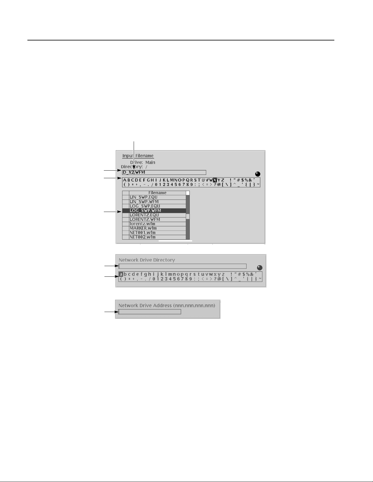
Operating Basics
Text Input
Character palette
When you need to assign a name to a waveform file or equation, or a IP address to
the instrument, the instrument displays a text dialog box. See Figure 2-11. The text
field is where you enter or change an existing character string. The character palette
is where you select alphanumeric characters to insert into the text field. You can
also select equation or file names from the name list to insert into the text field.
Caret
Tex t fi el d
Name list
Text field
Character palette
Text field
Figure 2-11: Three type of Input text dialog boxes
To select a character from the character palette, use the general purpose knob to
highlight a character, and then push the ENTER to insert the character into the text
field. Repeat this step until you have entered all characters in the text field. By
default, the character palette is selected. To select text from a file name list, use the
y and b arrow buttons to move the knob icon to the file name list. Table 2-2
describes all the controls you can use for entering and editing text.
2-22 AWG615 Service Manual

Shortcut Controls
Operating Basics
Table 2-2: Text input button functions
Control Description
General purpose knob Selects the character to insert into the text field.
a and ' arrow buttons Moves the character insertion caret left or right in the text field.
ENTER button Inserts the selected character or character string into the text field.
button Deletes one character to the left of the caret.
CLR button Clears the entire text field.
Numeric buttons Enters numeric characters into the text field.
SHIFT button Enters a selected character in upper case. When you push the SHIFT
button, the SHIFT LED lights. When the dialog box disappears, the
SHIFT LED also goes off.
Figure 2-12 shows the shortcut buttons and knobs that control specific instrument
setup parameters. Using the shortcut controls lets you adjust the output setup
parameters even while you are displaying another menu. Table 2-3 describes the
shortcut controls.
Figure 2-12: Shortcut controls
AWG615 Service Manual 2-23

Operating Basics
Table 2-3: Shortcut controls
Controls Description
VERTICAL
Displays the Vertical side menu. This is the same operation as selecting
SETUP (front)!Vertical (bottom).
Adjusts the vertical offset parameters. This is the same as selecting
SETUP (front)!Vertical (bottom)!Offset (side), and then turning the
general purpose knob. (except option 02)
Adjusts the amplitude parameters. This is the same as selecting SETUP
(front)!Vertical (bottom)!Amplitude (side), and then turning the
general purpose knob.
HORIZONTAL
mp
Displays the Horizontal side menu. This is the same as selecting SETUP
(front)!Horizontal (bottom).
Adjusts the clock setting. This is the same as selecting SETUP
(front)!Horizontal (bottom)!Clock (side), and then turning the
general purpose knob.
TRIGGER
Displays the Trigger side menu. This is the same as selecting
SETUP (front)!Tri gg er (bottom).
Adjusts the trigger level setting. This is the same as selecting
SETUP (front)!Tri gg er (bottom)!Level (side), and then turning the
general purpose knob.
2-24 AWG615 Service Manual

File Management
Operating Basics
This section is an overview of the instrument commands and operations for doing
file management tasks.
File Type Extensions
The AWG615 Arbitrary Waveform Generator uses numerous file formats to hold
different types of data. These file types are listed in Table 2-4. Note that the
instrument checks the file format and processes the file based on its content,
regardless of the file extension.
Table 2-4: AWG615 Arbitrary Waveform Generator file types
Files Description
Waveform file Use .wfm or .WFM suffix for identification.
Contains waveform data. All signal data must be in waveform format before it
can be output. Created with the waveform editor, by compiling an equation file,
or by converting to waveform format when importing waveforms from external
equipment.
Pattern file Use .pat or .PAT suffix for identification.
Contains pattern data. Created with the pattern editor.
Sequence file Use .seq or .SEQ suffix for identification.
Contains waveform sequence and trigger data. Created with the sequence
editor.
Equation file Use .equ or .EQU suffix for identification.
Contains equations or functions that describe a waveform. Created with the
equation/text editor. Both text editor and equation editor assign .txt suffix by
default, but use .equ suffix to avoid confusion with normal text file.
Text file Use .txt or .TXT suffix for identification.
Contains ASCII text. Created with the equation/text editor.
Setup file Use .set or .SET suffix for identification.
Contains instrument setup and configuration data of both AWG and FG mode.
Created from the SETUP menu.
AWG615 Service Manual 2-25

Operating Basics
Locating Files
There are three locations for storing waveform data on the AWG615 Arbitrary
Waveform Generator. Data can be stored on the instrument hard disk drive, the
instrument floppy disk drive, or a remote storage device accessible through the
Ethernet interface. If the file you want to load is not on the current drive, use the
EDIT menu main screen Drive and Directory bottom menu buttons to open side
menus that let you change the current drive location. Table 2-5 describes the Drive
and Directory bottom buttons.
Table 2-5: Drive and Directory menus
Bottom
menu
Drive Main
Directory Up Level
Side menu Description
Changes the instrument current drive. To select a drive, push
Floppy
Net1
Net2
Net3
Down Level
the appropriate side menu button. Note that there must be a
floppy disk inserted in the instrument floppy disk drive to select
the floppy drive.
Note that the label Net1, Net2 and Net3 vary depending on the
net name settings in the UTILITY menu.
Moves up a directory level.
Moves down a directory level. To move down a directory level,
select a directory name in the pop–up list, and then push the
Down Level side button. The filename list changes to show the
contents of the directory.
Copying Files
Make Directory
Archive
Extract
NOTE. In the following procedures, you may have to push the EDIT button twice
Creates a directory at the current level. To create a directory,
push the Make Directory side button to display the Input New
Directory Name dialog box. Enter the directory name in the
name field, then push the OK side button. The instrument
creates the new directory.
Creates a new file (.tar format) for archive from selected
directory. The archived file keeps hierarchic structure.
Restore the archived file (.tar) to the current directory.
to quit the editor. When the instrument does not display the file list, push the EDIT
button again. Refer to Saving Files on page 2-29.
You can copy files in from a double window or a single window. In a double
window, push the Copy button to copy the selected file in the active window into
the desired window.
Copying files in double windows. Do the following steps to copy files selected in
the active window:
1. Push EDIT (front) button and select the file to copy.
2. Push Window (bottom)
!Window (side) to select Double.
2-26 AWG615 Service Manual

Two file windows are displayed.
3. Push Select (side) to select the active window.
Operating Basics
4. Push Directory (bottom)
!Up Level, Down Level, or Make Directory (side)
to select the destination.
5. Push Select (side) to activate the window into which you are going to copy the
file and then select the file.
6. Push File (bottom)
!Copy (side) to copy the file to the destination as the same
file name.
If the directory name is the same as the destination directory name, you will be
asked to confirm to overwrite the file.
Copying files in single window. Do the following steps to copy files selected in
single window:
1. Push EDIT (front) button and select the file to copy.
2. Push File (bottom)
!Copy (side) and select the file name and destination.
3. Push OK (side) to copy the file.
The file is copied and renamed.
NOTE. For additional file copying and file moving procedures, refer to Double
Windows on page 2-32.
Moving Files
To move a file in the double window, do the following steps:
1. Push EDIT (front) button and select the file to copy.
2. Push Window (bottom)
!Window (side) to select Double.
Two file windows are displayed.
3. Push Select (side) to select the active window.
4. Push Directory (bottom)
!Up Level, Down Level, or Make Directory (side)
to select the destination.
5. Push Select (side) to activate the window into which you are going to move the
file and then select the file.
6. Push File (bottom)
!Move (side) to move the file to the destination.
If the directory name is the same as the destination directory name, you will be
asked to confirm to overwrite the file.
AWG615 Service Manual 2-27

Operating Basics
Renaming Files
Deleting Files
Renaming files is similar to Copying files, but the original files are deleted. Do the
following steps to rename a file:
1. Push EDIT (front).
The instrument displays the file list.
2. Select the file to rename.
3. Push File (bottom)!Rename (side).
4. Enter the new name for the file in the file name field.
5. Push OK (side).
The file is renamed.
Do the following steps to delete a file:
1. Push EDIT (front). The instrument displays the file list.
2. Select the file to delete.
3. Push File (bottom)!Delete (side). The instrument displays a message box
asking you to confirm deleting the file.
4. Push OK (side) to delete the file, or Cancel to cancel the operation and keep
the file.
Read Only Attribute
You can also delete all files on the current drive and directory by doing the
following steps:
1. Push EDIT (front)!File (bottom)!Delete All (side).
The instrument displays a message box asking you to confirm deleting all files.
2. Push OK (side) to delete all files, or Cancel to cancel the operation and keep
all files.
You can change the read only or read/write attributes on a file. Do the following
steps to change the file attribute:
1. Push EDIT (front).
The instrument displays the file list.
2. Select the file to change the attribute.
3. Push File (bottom)!Attribute xxxx (side).
The xxxx is the Read/Write or Read Only attribute of the selected file. Pushing
this side button immediately changes the file attribute.
The file with a read only attribute is marked by , and the directory by . See
Figure 2-13.
2-28 AWG615 Service Manual

File with read only
Directory with read only
Operating Basics
Attribute
side button
Saving Files
Figure 2-13: Files and directories with read only attribute
You can save files from each editor screen. You have the choice of saving your
waveform data to the current file name or to a new file name. To save a waveform
to its current file name, push File (bottom)!Save (pop–up)! OK (side).
If you are saving a waveform for the first time, the instrument opens the Input
Filename dialog box, shown in Figure 2-14. Use this dialog box to enter a file
name. If necessary, you can select a different storage media or directory by pushing
the Drive... side menu button. Enter the file name, then push the OK side button or
the ENTER front–panel button to close the dialog box and save the file.
Figure 2-14: Input Filename dialog box
AWG615 Service Manual 2-29

Operating Basics
NOTE. When you exit an editor without saving edited data, the instrument displays
the message Save the changes you made? Push the Ye s side button to save the
waveform data.
To save waveform data to a new file name, push File (bottom)!Save As
(pop–up)!OK (side). The instrument opens the Input Filename dialog box, shown
in Figure 2-14. Use this dialog box to enter a file name. If necessary, you can select
a storage media or directory by pushing the Drive... side menu button. Enter the file
name, then push the ENTER front–panel button to close the dialog box and save
the file.
If you are saving a file with a record length larger than 960 data points and the
record is not evenly divisible by four, the instrument needs to adjust the record
length to meet internal memory record length requirements. The instrument
displays one of the messages shown in Table 2-6. You can push the OK side button
to accept the recommended change, or cancel the save and then edit the file to
satisfy the data record length requirements.
Archive, Extract
Table 2-6: Waveform record length adjustment messages
Message Description
Leave as it is The data is saved, as it is, without making changes. The instrument will
display an error message if you try to load a file that does not meet the
instrument waveform constraints.
Append 0 With Level–0 data added after the data, a file with a data length meeting
the requirements is created.
Expand With the waveform data expanded, a file with a data length meeting the
requirements is created.
Expand with Clock With the waveform data expanded, a file with a data length meeting the
requirements is created. In addition, the clock frequency increases without
change in scaling factor. The settings are saved in the file.
Repeat With repetitions of the original data linked, a file with a data length meeting
the requirements is created. If the total length of the linked data exceeds
32.4M/64.8M (option 01) points, this will cause an error.
To archive or extract files, do the following steps.
Archive. When you select Directory in the file list, you can make archives for all
the files in the directory and subdirectory.
1. Push EDIT (front).
The instrument displays the file list.
2. Select the file to make archive files.
2-30 AWG615 Service Manual

Operating Basics
3. Push Directory (bottom)!Archive (side).
The instrument displays the Input archive name dialog box. By default, the
name of <directory name>.tar is automatically assigned. If necessary, you can
change the name.
4. Push OK button, and the archive file will be created in the current directory.
Extract. The archived file is extracted (restored) to the current directory. If the
directory already exists, the existing file will be overwritten.
1. Push EDIT (front).
The instrument displays the file list.
2. Select the file to extract.
3. Push Directory (bottom)!Extract (side).
The instrument extracts the archived files and directories to current directory.
Remote computer archive operation. AWG615 Arbitrary Waveform Generator
uses .tar format files. Use the tar command when you archive with a remote
computer environment. If you are PC user, use tar format archive tool.
The following list describes some restrictions on archive and extract operation.
Blocking factor is 20.
The file name including the file path in the directory is up to 100.
The depth of directory hierarchy is up to 16.
Use the following command to make archive file:
tar [–] cvf <tar file name> <file name or directory name>
Use the following command to extract archive file:
tar [–] xvf <tar file name>
AWG615 Service Manual 2-31

Operating Basics
Double Windows
Upper Window
When the Window bottom button is displayed, you can split the file list in the Edit
Screen into two lists as shown in Figure 2-15. This function is called Double
Windows.
Lower Window
Window Operation
Figure 2-15: Double windows
In Double Windows, for example, you can display the hard disk and floppy disk
file lists or the file list of two separate directories. All the functions invoked from
the bottom buttons operate the same in single window except for the File function.
The two most important functions used in the Double Windows are the Copy and
Move file operations. These operations are discussed in Window Operation below.
The split windows are named Upper window and Lower window as indicated in
Figure 2-15. You must select a window for operation.
When you push EDIT (front)
appears. Push the Window side button to select Double. Double windows are
displayed. Push the Window side button once more to select Single. The display
returns to the single file list.
! Window (bottom), the Window side button
2-32 AWG615 Service Manual

Operating Basics
When you display the double windows, the Select side button will be available.
Push the Select side button to select Upper for file operation in the upper file list
window. Push the Select side button once more to select Lower for file operation
in the lower file list window.
Operation in Double
Window
The most useful functions in the Double Windows may be those invoked from the
File bottom button. The functions available in the File bottom button are described
in Table 2-7.
Table 2-7: File operation in double windows
Operation Description
Copy Copies a file selected in a selected file list window into the destination
specified in the other file list window.
You cannot select the directory.
Copy All Copies all files in a selected file list window into the destination specified
in the other file list window.
You cannot copy the directory or directory structure.
Move Moves a file selected in a selected file list window into the destination
specified in the other file list window.
You cannot select the directory.
Move All Moves all files in a selected file list window into the destination specified
in the other file list window.
You cannot move the directory or directory structure.
NOTE. You cannot use the Rename, Delete, Delete All, and Attribute side buttons
unless you display the single file list window.
When the files with the same file name exist in a destination in a copy or move
operation, the message Overwrite existing file <filename> appears. At the same
time, the Cancel, No, Yes to All and Ye s side buttons appears. Press any of these
side buttons to continue the procedure. See Table 2-8.
AWG615 Service Manual 2-33

Operating Basics
Figure 2-16: Overwrite confirmation
Table 2-8: Confirmation selection for copy–all and move–all operations
Side menu Description
Cancel Cancels and stops copy or move operation.
No Skips the copy or move operation for the file indicated in the message.
Yes to All Overwrites all the files without displaying any messages until the
operation is finished.
Yes Overwrites the file indicated in the message and proceeds with the
operation.
You cannot copy or move the directory. In the copy–all or move–all operations, the
message Directory cannot be copied appears if you try to move or copy a directory.
Press the OK side button to confirm and proceed with the operation.
2-34 AWG615 Service Manual

Quick View
Operating Basics
Before loading or handling a file, you sometimes want to look at the content of a
file to confirm the operation. The quick view function displays the view window
and allows you to view a waveform or pattern file selected in a file list. This
function is always available when a file list is displayed on the screen. See Figure
2-17.
Figure 2-17: File list window examples in which Quick View is available
Select a file from the file list window using the general purpose knob. Press the
SHIFT and ENTER front–panel buttons simultaneously. The view window
displaying the waveform or pattern appears as shown in Figure 2-18.
AWG615 Service Manual 2-35

Operating Basics
Figure 2-18: Viewing a file by Quick View function
Push the OK side menu button to close the view window. You cannot view files
other than waveform or pattern in this function.
This function is always available when a file list window or file list dialog box is
displayed on the screen.
2-36 AWG615 Service Manual

Setup Overview
Operating Basics
The Setup screen is where you load and set up the waveform for output. This
section gives you an overview of the Setup screen, how to load a file, how to set
the signal output parameters, and how to enable signal output.
Main Setup Screen
Wavefor m
parameter icons
Number of points for
loaded waveform
To display the main Setup screen, push the SETUP front–panel button. The
instrument displays the main Setup screen as shown in Figure 2-19. Table 2-9
describes the screen waveform parameter icons. Table 2-10 lists the bottom menu
functions.
Clock frequency Run mode Instrument status
Side
menu
area
Bottom menu
Figure 2-19: Main Setup screen (except option02)
AWG615 Service Manual 2-37

Operating Basics
Table 2-9: Setup screen parameter icons
Icon Description Icon Description
Displays the file name of the
waveform, pattern, or
sequence file loaded for
output.
Note: use the View button to
display the loaded waveform.
Displays the lowpass filter
setting through which the
waveform is passed.
(except option 02)
Displays the peak–to–peak
signal amplitude setting.
Displays the signal offset
setting.
(except option 02)
Displays the digital output and
marker signal minimum and
maximum voltage settings.
Indicates that the channel
output is enabled or disabled.
If the switch is shown open,
that channel output is
disabled.
Indicates that the marker
output is enabled or disabled.
All Marker outputs are
controlled by the ALL
MARKER OUT ON/OFF
button.
Table 2-10: Setup bottom menu buttons
Bottom menu
button
Waveform/Sequence Displays the side menu for loading, viewing, editing waveform files, and for
Vertical Displays the Vertical side menu for setting waveform peak–to–peak
Horizontal Displays the Horizontal side menu for setting the clock source, clock
Run Mode Displays the Run Mode side menu for setting the instrument run mode.
Trigger Displays the Trigger side menu for setting trigger source, slope, level,
Save/Restore Displays the Save/Restore side menu to save and restore setup output
Extended Operation Displays the Extended Operation side menu to change the operation mode
Description
entering the FG mode main screen.
amplitude, offset, lowpass filter, marker, and other output parameters.
The product which has option 02 doesn’t have offset and lowpass filter
function.
frequency, and marker signal delay parameters.
Refer to Run Modes in the Reference section for an explanation of the
different run modes.
external trigger impedance, and interval parameters.
parameters.
such as FG mode, Waveform Mixing mode and Synchronous Operation
mode.
2-38 AWG615 Service Manual

Operating Basics
Loading a Waveform File
to Output
Do the following steps to load a waveform file into the Setup screen:
1. Push the Waveform/Sequence bottom menu button.
This opens the Waveform/Sequence side menu.
2. Push the Load... side button. The instrument opens the Select File list as shown
in Figure 2-20.
Figure 2-20: Select File dialog on the Load menu
3. Use the general purpose knob or y and b arrow buttons to select the file name
to load. If the file you want to load is located in a different drive or directory,
use the side menu buttons to change the current drive.
4. Push the ENTER front–panel button or OK side button. The instrument loads
the file and displays the file name in the selected channel file icon. Push the
Cancel side button to exit the file load process.
The procedures above explains how to load a waveform or pattern into the
waveform memory, and/or sequence file into the sequence memory, which will be
scanned to output. The waveform memory, sequence memory and the edit buffer
are completely independent. So, you can edit a waveform, pattern, sequence or
equation/text while outputting an another waveform or sequence.
However, when you push SETUP (front–panel)!Waveform/Sequence
(bottom)!Edit (side) to copy the waveform in the waveform memory to the edit
AWG615 Service Manual 2-39

Operating Basics
buffer, you must save the currently edited waveform, pattern, sequence or
equation/text into a file.
You can enter into the QUICK EDIT mode only from the waveform editor. When
you enter into the quick edit mode, the instrument copies the data in the edit buffer
into the undo buffer. All the changes you make immediately reflect to the data in
the edit buffer, and also to the data in the waveform memory if that data is being
loaded to output.
Before loading, you can view a waveform or pattern. Refer to Quick View on page
2-35 for more detail.
Viewing a Waveform
To view the loaded waveform file, push the View side menu button. The instrument
opens a window on the screen that displays the waveform, as shown in Figure 2-21.
Push the OK side menu button or ENTER front–panel button to close the view
window.
Figure 2-21: Viewing a file in the Setup screen
Note that the View function does not display the waveform in the waveform
memory, but displays the waveform in the file that you specified. Even though you
change the waveform with the editor and update the waveform memory, the View
function still displays the waveform before the update unless you save the file.
2-40 AWG615 Service Manual

Operating Basics
Editing a Waveform
Setting Waveform Output
Parameters
To edit the loaded waveform file, push the Edit... side menu button. The instrument
opens the appropriate edit window for the previously loaded file type.
If you have not loaded a file in the Setup screen, the instrument displays the
message No output data, and you cannot enter into the editor.
The editors are described in more detail in the Reference section of the User
manual.
The Setup side menus provide commands for setting and adjusting waveform
output parameters. The steps for setting output parameters are discussed in detail
in the Reference section of the User manual. Table 2-11 provides an overview of
the Setup side menu operations.
Table 2-11: Setup output parameter operations
Bottom
button
Wavefor m/S eq
uence
Side
button Description
Load...
View
Displays the Select File dialog box that lists files in the current
drive and directory. Select a file to load or use the side menu
buttons to change drives and/or directories.
Displays the loaded file in a window. Push the OK side menu
button to close the view window.
Edit...
Vertical Filter
Amplitude
Offset
Marker...
Output...
Opens the appropriate editor for the loaded file.
Selects lowpass filter to insert into signal path. Filter values
are Through (no filter), 20 MHz, 50 MHz, 100 MHz, and 200
MHz. Use the general purpose knob to enter new
values.(except option 02)
Sets the signal peak–to–peak amplitude in increments of
0.001 V. The maximum value is 2 V
V
in direct mode. Use the general purpose knob or the
p–p
keypad to enter new values.
Sets the signal offset value in increments of 0.001 V. The
offset voltage range is ±0.5 V. Use the general purpose knob
or the keypad to enter new values.(except option 02)
Displays a side menu to set Marker 1 and Marker 2 signal high
and low values. The marker signal voltage range is -2.0 V to
2.45 V and maximum amplitude is 1.25 V
the general purpose knob or the keypad to enter new values.
Toggles normal output to direct output.(except option 02)
in normal mode and 1
p–p
into 50 Ω . Use
p–p
AWG615 Service Manual 2-41

Operating Basics
Table 2-11: Setup output parameter operations (cont.)
Bottom
button
Horizontal Clock
Run Mode Continuous
Trigger Source
Side
button Description
Clock Ref
Clock Src
Triggered
Gated
Enhanced
Slope
(or Polarity)
Level
Impedance
Sets the clock sample rate from 50 kS/s to 2.7 GS/s.
Sets the reference clock source to either Internal or External.
A valid external clock signal is 10 MHz ±0.1 MHz with a
voltage level of 0.2 to 3.0 V
Sets the clock source to either Internal or External. A valid
external clock signal is 125 MHz to 2.7 GHz with a voltage
level of 0.4 to 2.0 V
Displays the Run Mode side menu for setting the instrument
run mode. Refer to The Run Mode Menu section on page 3-3
for an explanation of the different run modes.
Sets trigger source to Internal or External. If Exter nal selected,
all other side menu items are not selectable except Interval.
Sets the trigger slope or gate polarity to Positive or Negative.
Sets the trigger signal level. The trigger level range is ±5.0 V
in 0.1 V increments.
Sets the external trigger input line impedance to either 50 Ω
or 1 kΩ.
p–p
.
p–p
.
Outputting a Waveform
Interval
Save/Restore Save Setup
Restore Setup
Extended
Operation
FG...
Wavefor m
Mixing...
Sync Master...
Sync Slave...
Sets trigger interval from 1.0 µs to 10.0 s.
Save the setup parameters set by SETUP window and
Extended Operation mode window as a setup file.
Restore a setup file.
Enters the FG mode for easy generate of standard functional
waveform.
Enter the Waveform Mixing mode.
Enter the Sync-Master of the Synchronous Operation mode.
Enter the Sync-Slave of the Synchronous Operation mode.
To output a loaded waveform, push the CH 1 OUT and/or CH 1 OUT and/or ALL
MARKER OUTPUT ON/OFF front–panel button(s), then the RUN front–panel
button. The LEDs near each button light up to indicate they are enabled. The
instrument outputs the waveform depending on the Run mode. You can turn either
or both channel outputs and marker outputs on or off while the instrument is
running by pushing the CH 1 OUT or CH 1
OUT or ALL MARKER OUTPUT
ON/OFF buttons. To stop the waveform output, push the RUN button so that the
LED turns off.
2-42 AWG615 Service Manual

Operating Basics
Saving and Restoring
Setup Parameters
The waveform or pattern file contains only the waveform and clock information.
When you load a waveform or pattern file, the output signal will use the current
instrument setup parameters.
To save you from doing a manual setup procedure each time you load a waveform,
the AWG615 Arbitrary Waveform Generator lets you save setup parameters into a
setup file. You can then restore the saved settings for use with waveforms.
The setup parameters of the AWG mode and the Extended Operation mode are
saved in a setup file. When a setup file is restored, settings in both AWG mode and
Extended Operation mode will replace the contents of a setup file.
Do the following steps to save the current setup parameters:
1. Push SETUP (front)!Save/Restore (bottom)!Save Setup (side).
The Input Filename dialog box appears.
2. Enter a setup file name.
The setup file name must have the extension .set.
3. Push the OK side button.
The setup information is saved to the designated file.
Do the following steps to restore setup parameters from a file:
1. Select SETUP (front)!Save/Restore (bottom)!Restore Setup (side).
The message box displaying Restoring setup destroys current settings.
appears. The instrument then opens the Select Setup Filename dialog box.
2. Enter or select the setup file name to load.
3. Push the OK side button to load the file and restore the setup parameters, or
push the Cancel side button to exit the restore process without loading the
setup file.
AWG615 Service Manual 2-43

Operating Basics
2-44 AWG615 Service Manual

Theory of Operation

 Loading...