

Page 1

xx
AWG5200 Series
Arbitrary Waveform Generators
ZZZ
Specifications and Performance Verification
Technical Reference
Rev A
Warning
The servicing instructions are for use by qualified personnel
only. To avoid personal injury, do not perform any servicing
unless you are qualified to do so. Refer to all safety summaries
before performing service.
www.tek.com
077-1335-01
Page 2

Copyright © Tektronix. All rights reserved. Licensed software products are owned by Tektronix or its subsidiaries
or suppliers, and are protected by national copyright laws and international treaty provisions.
Tektronix products are c overed by U.S. and foreign patents, issued and pending. Information in this publication
supersedes that in all previously published material. Specifications and price change privileges reserved.
TEKTRONIX and TEK are registered trademarks of Tektronix, Inc.
Contacting Tektronix
Tektronix, Inc.
14150 SW Karl Braun Drive
P.O . B ox 50 0
Beaverto
USA
For product information, sales, service, and technical support:
n, OR 97077
In North America, call 1-800-833-9200.
Worldwide, visit www.tek.com to find contacts in your area.
Page 3

Table of Contents
General safety summary ........................ ................................ ................................ ... v
Service safety summary.......................................................................................... vii
Preface.............................................................................................................. ix
Related doc
Specifications .......... ................................ ................................ ............................. 1
Performance conditions ........................ ................................ ............................... 1
Electrical specifications ............................ ................................ ........................... 2
Mechanical characteristics ......................... ................................ .......................... 21
Environmental characteristics ......... ................................ ................................ ...... 23
Perform
Brief procedures ................................................................................................... 27
Perf
ance verification procedures ............................................................................ 25
Input and output options ..................................................................................... 26
Diagnostics .................................................................................................... 27
Calibration ......................... ................................ .................................. .......... 28
Functional test................................................................................................. 30
ormance tests........ ................................ .................................. ........................ 42
Prerequisites ............................... ................................ .................................. .. 42
Required equipment .......... .................................. ................................ .............. 42
Termination resistance measurement ........................... .................................. .......... 44
Analog amplitude accuracy . ... . . . ... . ... . .... . . ... . ... . .... .. ... . ... . .... . . ... . ... . .... .. ... . ... . .... . . ... . . 45
Analog offset accuracy (DC output paths) ................................................................. 51
alog DC Bias accuracy (AC output paths).............................................................. 54
An
Marker high and low level accuracy........................................................................ 58
10 MHz reference frequency accuracy ..................................................................... 63
Test record ..................................................................................................... 64
uments...................................... ................................ ...................... ix
AWG5200 Series Technical Reference i
Page 4

Table of Contents
List of Figure
Figure 1: Peripheral connections ................ .................................. .............................. 26
Figure 2: 1 G
Figure 3: Equipment connection to measure terminator resistance ...................... .................... 44
Hz output waveform....................................... ................................ ........ 38
s
ii AWG5200 Series Technical Reference
Page 5

List of Tables
Table 1: Run mode .......................... ................................ ................................ ....... 2
Table 2: Arbitrary waveform ......................... ................................ ............................. 2
Table 3: Real time digital signal processing..................................................................... 3
Table 4: Sequencer ........................ ................................ ................................ ......... 3
Table 5: Sample clock generator........................... ................................ ....................... 4
Table 6: Analog output skew..................... ................................ ................................. 4
Table 7: Signal output characteristics ............... ................................ ............................. 5
Table 8: Harmonic distortion (DC High
Table 9: Harmonic distortion (AC Direct output path)........................................................ 12
Table 10: Harmonic distortion (AC Amplified output path) ................................ .................. 12
Table 11: SFDR operating at 2.5 GS/s ................ ................................ .......................... 12
Table 12: SFDR operating at 5 GS/s ...................... .................................. .................... 13
Table 13: SFDR operating at 10 GS/s ................................. ................................ .......... 13
Table 14: Phase noise operating at 2.5 GS/s.... .................................. .............................. 14
Table 15: Phase noise operating at 5.0 GS/s or 10 GS/s with DDR enabled................................ 14
Table 16: Marker outputs ................. ................................ .................................. ...... 14
Table 17: 10 MHz Ref Out (reference output) ................................................................. 15
Table 18: Ref In (reference input) ............................................................................... 15
Table 19: Clock Out............................................................................................... 15
Table 20: Clock In..................... ................................ ................................ ............ 16
Table 21: Sync In........................ ................................ .................................. ........ 16
Table 22: Sync Out ................................................................................................ 16
Table 23: Sync Clock Out ........................ ................................ ................................ 17
Table 24: Trigger Inputs .......................................................................................... 17
Table 25: Pattern Jump In connector ................ ................................ ............................ 19
Table 26: Auxiliary Outputs (Flags). ... . ... . .... . . ... . ... . ... . ... . ... . .... .... . . ... . ... . ... . ... . ... . .... .... .. .. 20
Table 27: Computer
Table 28: Display.................................................................................................. 20
Table 29: Power supply... .................................. ................................ ...................... 20
Table 30: Mechanical characteristics............................................................................ 21
Table 31: Environmental characteristics ........................................................................ 23
Table 32: Required equipment for the functional test ......................... ................................ 30
Table 33: Required equipment for performance tests ..................... .................................. .. 42
Table 34: Analog amplitude accuracy (DC High BW output path). ... . ... . .... .. ... . ... . ... . . . ... . ... . ... . . 46
Table 35: Analog amplitude accuracy (DC High Volt output path). .. ... . ... . ... . .... .. ... . ... . ... . .... .. ... 50
Table 36: Offset accuracy ........ ................................ ................................ ................ 53
Table 37: Analog DC bias accuracy............................................................................. 56
Table 38: Marker high level accuracy..................... ................................ ...................... 60
Table of Contents
BW output path).................................................... 11
system .................. .................................. ................................ .. 20
AWG5200 Series Technical Reference iii
Page 6

Table of Contents
Table 39: Marke
r low level accuracy.............................................. .............................. 61
iv AWG5200 Series Technical Reference
Page 7

General safety summary
General safet
To avoid fir
e or personal
injury
y summary
Review the fo
this product or any products connected to it.
To avoid pot
Only qualified personnel should perform service procedures.
Use proper
certified for the country of use.
Ground th
of the power cord. To avoid electric shock, the grounding conductor must be
connected to earth ground. Before making connections to the input or output
terminals of the product, ensure that the product is properly grounded.
Observe all terminal ratings. To avoid fire or shock hazard, observe all ratings
and markings on the product. Consult the product manual for further ratings
information before making connections to the product.
Do not apply a potential to any terminal, including the common terminal, that
exceeds the maximum rating of that terminal.
llowing safety precautions to avoid injury and prevent damage to
ential hazards, use this product only as specified.
power cord. Use only the power cord specified for this product and
e product. This product is grounded through the grounding conductor
Power disconnect. The power cord disconnects the product from the power source.
Do not block the power cord; it must remain accessible to the user at all times.
Do not operate without covers. Do not operate this product with covers or panels
removed.
Do not operate with suspected failures. If you suspect that there is damage to this
product, have it inspected by qualified service personnel.
Avoid exposed circuitry. Do not touch exposed connections and components when
power is present.
Do not operate in wet/damp conditions.
Do not operate in an explosive atmosphere.
Keep product surfaces clean and dry.
Provide proper ventilation. Refer to the manual's installation instructions for details
on installing the product so it has proper ventilation.
AWG5200 Series Technical Reference v
Page 8

General safety summary
Termsinthismanual
Symbols and terms on the
product
These terms may
WARNING. Warning statements identify conditions or practices that could result
in injury or loss of life.
CAUTION. Caution statements identify conditions or practices that could result in
damage to this product or other property.
These terms may a ppear on the product:
DANGER in
the marking.
WAR NI NG
read the marking.
CAUTIO
The following symbol(s) may appear on the product:
appear in this manual:
dicates an injury hazard immediate l y accessible as you read
indicates an injury hazard not immediately accessible as you
N indicates a hazard to property including the product.
vi AWG5200 Series Technical Reference
Page 9

Service safety summary
Service safet
ysummary
Only qualifie
safety summary and the General safety summary before performing any service
procedures.
Do not service alone. Do not perform internal service or adjustments of this
product unless another person capable of rendering first aid and resuscitation is
present.
Disconnect power. To avoid electric shock, switch off the instrument power, then
disconnect the power cord from the mains power.
Use care when servicing with power on. Dangerous voltages or currents may exist
in this p
test leads before removing protective panels, soldering, or replacing components.
To avoi
d personnel should perform service procedures. Read this Service
roduct. Disconnect power, remove battery (if applicable), and disconnect
d electric shock, do not touch exposed connections.
AWG5200 Series Technical Reference vii
Page 10

Service s afety summary
viii AWG5200 Series Technical Reference
Page 11

Preface
Related documents
This manual contains specifications and performance verification procedures for
the AWG5200 Series Arbitrary Waveform Generators.
The following documents are also available for this product and can be
downloade
AWG5200 Series Installation and Safety Manual. This document provides
safety in
071-3529-xx.
d from the Tektronix website www.tek.com/manual/downloads.
formation and how to install the generator. Tektronix part number:
AWG5200 S
programming commands to remotely control the generator. Tektronix part
number: 077-1337-xx.
AWG5200 User Manual. This document is a printable version of the
AWG5200 help system. Tektronix part number: 077-1334-xx.
eries Programmer Manual. This document provides the
AWG5200 Series Technical Reference ix
Page 12

Preface
x AWG5200 Series Technical Reference
Page 13

Specifications
Performance conditions
This section contains the specifications for the AWG5200 series Arbitrary
Waveform Generators.
All specifications are typical unless noted as warranted. Warranted specifications
that are marked with the
To meet speci fications, the following conditions must be met:
The instrument must have been calibrated/adjusted at an ambient temperature
between +20 °C and +30 °C.
The instrument must be operating within the environmental limits. (See
Table 31 on page 23.)
The instrument must be powered from a sourc e that meets the specifications.
(See Table 29 on page 20.)
The instrument must have been operating continuously for at least 20 minutes
within the specified operating temperature range.
symbol are checked in this manual.
AWG5200 Series Technical Reference 1
Page 14

Specifications
Electrical sp
ecifications
Table 1: Run mode
Characteris
Continuous m
Triggered mode
Triggered
tics
ode
continuous mode
Description
An arbitrary
An arbitrar
is output, the instrument waits for the next trigger signal.
An arbitrary waveform is output continuously after a trigger signal is applied.
waveform is output continuously.
y waveform is output only once when a trigger signal is applied. After the waveform
Table 2: Arbitrary waveform
Characteristics Description
Waveform memory Real Waveforms: 2 Gs/channel
Complex waveforms: 1 Gs/channel
Minimum waveform size
Continuous run mode
Triggered run modes or sequence
Waveform granularity
Continuous run mode
Triggered run modes 1 sample
IQ (Complex) waveform support IQ waveforms, referred to as “Complex waveforms”, are supported for use with real time
1 sample
Real waveform: 2400 samples
Complex waveform: 1200 samples
Real waveforms are waveforms that have a single input value for each sample point. IQ
waveforms, referred to as “Complex waveforms”, use 2 values for each sample point.
1 sample
digital up-conversion and play out. The carrier signal is generated independently of the
waveform with an NCO (Numerically Controlled Oscillator).
The w aveform requires 2 values for each sample point. In the IQ waveform, I and Q
samples alternate in pairs or groups depending on the interpolation selection. The
format depends on the interpolation rate selected (2x or 4x)
2 AWG5200 Series Technical Reference
Page 15

Specifications
Table 3: Real ti
Characteristics Description
Double Data Rate Interpolation (DDR
Mode)
Digital Up-conversion (DIGUP license
required)
Waveform interpolation Real time interpolation of IQ (complex) waveforms is supported independently on each
Inverse SINC filter Real time correction of the sinx/x frequency roll off can be enabled or disabled
me digital signal processing
Enabling DDR mode increases the output sample rate to 5 to 10 GS/s (2*fclk) and
interpolates the input sample data by 2X to match the output rate. 2X interpolation is
required for
With DDR enabled, the output image moves from ( fclk - fout) to (2*fclk - fout). Because
the input data rate does not increase, the output bandwidth remains (fclk/2).
DDR is most u
to specify the output center frequency up to the DDR Nyquist frequency. When the
waveform is a traditional, real valued, waveform (not IQ), enabling DDR applies a low
pass filter a
(fclk/2) and (2*fclk - fclk/2).
The DAC system in each channel includes a digital IQ modulator and numerically
controlled oscillator (NCO ) that provides digital up-conversion to a specified carrier
frequenc
Digital up-conversion requires an IQ input waveform. In the IQ waveform I and Q
samples alternate in pairs or groups depending on the interpolation selection.
Digital u
interpolation w hen a lower waveform sample rate is needed.
channel during play out.
Suppor
Only IQ (complex) waveforms can be interpolated. The interpolation factor refers to the
sample rate of the complex pair of points relative to the global instrument sample rate
set by t
factor is 2, then the waveform sample rate of both I and Q samples is 2.5 GS/s. DDR
interpolation offers an additional doubling o f the sample rate.
indep
sample rates above 5.0 GS/s.
seful when combined with digital up-conversion which allows the user
t a frequency just below (fclk/2) so that no signal is generate between
y
p-conversion can only be used with sample rates between 2.5 and 5 GS/s. Use
ted interpolation rates are 2x and 4x.
he clock. For example if the sample rate is set to 5 GS/s and the interpolation
endently on each channel.
Table 4: Sequencer
Characteristics Description
Number of steps
Maximum repeat count
16,384
14 address bits. Numbers are zero-0 based in HW (0 to -16383).
1048576 (2
20
)
AWG5200 Series Technical Reference 3
Page 16

Specifications
Table 5: Sample
Characteristics Description
Sample rate The sample clock frequency is a global parameter that applies to all channels. DDR can be
DDR enabled:
DDR disabled
Sample rate resolution
Jitter Reduction Mode (PLL
integer mode)
Without Jitter Reduction (PLL
FracN mode)
Sample rate frequency
accuracy
10 MHz reference accuracy
clock generator
enabled on a per channel basis allowing the sam ple rate to be doubled on selected channels.
The sample cl
lower than 2.5 GS/s, the system replicates points. The number of replicated points increases
by powers of 2, therefore the clock frequency is SR×2
a frequency
When using complex waveforms digital up conversion, the sample rate is limited to 2.5 GS/s to
5 GS/s. To achieve lower sample rates, use waveform interpolation.
Real waveforms: 596 S/s to 10 GS/s
Complex (I
Real wave
Complex (IQ) waveforms: 2.5 GS/s to 5 GS/s
3 digits with jitter reduction (50 MHz sample clock frequency steps from 2.5 GHz to 5 GHz).
With DDR enabled, the resolution is 100 MHz Sample rates below the clock range are a power
of 2 div
the 50 MHz stepped frequencies.
8digit
Sample Rate * 10 MHz Ref Accuracy/10 MHz
Examp
10 MHz ± 20 Hz
perature between 0 to 50 °C; includes aging within 1 y ear of calibration.)
(Tem
ock frequency is always between 2.5 GHz and 5 GHz. To achieve sample rates
n
,. where n is an integer that results in
between 2.5 GHz and 5 GHz.
Q)waveforms: 5GS/sto10GS/s
forms: 298 S/s to 5 GS/s
ision of the clock frequency so Low Jitter sample rates are a power of 2 divisions of
s
le:5GS/s*(±20Hz)/10MHz=10kHz
Table 6: Analog output skew
Characteristics Description
Skew between (+) and (–) outputs
Skew between channels
(DC high BW mode only)
Delay change from DC High BW
output path to other output paths
DC High Volt
(Option HV)
AC Direct
AC Amplified
(Option AC)
Skew adjustment range
±15 ps
±25 ps
Skew is calibrated using the (+) outputs of the DC High BW output path for each channel.
Channel delay will change when a different path is selected or when various DAC features are
enabled.
1.2 ns
340 ps
740 ps
±2 ns
Used to adjust skew between channels in a single instrument.
4 AWG5200 Series Technical Reference
Page 17

Specifications
Table 6: Analog output skew (cont.)
Characteristics Description
Skew adjustment resolution 250 fs
Skew stability between channels
Sync out to channel < ±0.5 ps/ °C
Channel to channel < ±0.5 ps/ °C (±0.18 ps/ ° C @ 1 GHz)
Phase adjustment Used to adjust skew between all channels in an instrument relative to another instrument.
Range
Resolution
-8,640° to +8,640° of the DAC clock.
1° of the DAC clock.
Table 7
Characteristics Description
Connector type 2 SMA connectors per channel.
Number of outputs AWG5202: 2.
DAC
Type of outputs
ON/OFF control Independent control for each analog output channel.
Output impedance 50 Ω
: Signal output characteristics
AWG5204: 4.
208: 8.
AWG5
resolution
Output path
DC High BW (+) and (–) complementary (differential).
DC High Volt
(Option HV)
AC Direct Single ended output from the (+) connector.
AC Amplified
(Option AC)
16, 15, 14, 13 or 12 bits.
bling markers degrades resolution.
Ena
16-bit mode: 0 markers available.
15-bit mode: 1 marker, M1.
bit mode: 2 markers, M1, M2.
14-
13-bit mode: 3 markers, M1, M2, M3.
12-bit mode: 4 markers, M1, M2, M3, M4.
Includes a variable gain, high bandwidth, DC coupled amplifier in the signal path.
(+) and (–) complementary (differential).
An additional amplifier adds high amplitude with reduced bandwidth.
A direct connection to the DAC output including a balun to reduce common mode distortion.
The AC Direct path offers the lowest noise and distortion performance.
Single ended output from the (+) connector.
Includes an amplified path and a passive variable attenuator path to provide a large output
amplitude range.
AWG5200 Series Technical Reference 5
Page 18

Specifications
Table 7: Signal output characteristics (cont.)
Characteristics Description
VSWR/return loss
Output path
DC High BW
(Includes option DC)
AC Direct 10 MHz to 1 GHz < 1.6:1.
AC Amplified
(Option AC)
Output Modes
NRZ
RZ
MIX Mode
Sin(x)/x Bandwidth 4.44 GHz * fsample ÷ 10 GS/s (DDR Mode).
Amplitude control
Amplitude range
Output path
DC High B W 25 mV
DC High BW
(Option DC)
DC High Volt
(Option HV)
DC to 1 GHz < 1.4:1.
1 GHz to 3 GHz < 1.6:1.
3 GHz to 4 GHz < 2.0:1.
1 GHz to 4 GHz < 2.0:1.
10 MHz to 1 GHz < 1.4:1.
2 GHz to 4 GHz < 1.5:1.
In NRZ mode, each sample is held for the entire sam ple period (1/sample rate). This results
in the familiar sin(x)/x frequency response. With DDR mode enabled, the sin(x)/x bandwidth
doubles.
In RZ mode, each sample is held for half of the sample period. This doubles the sin(x)/x
bandwidth, but reduces the amplitude by half. This may be useful when playing a real
waveform with the signal in the second Nyquist zone. For real waveforms, DDR mode filters
the signal in the 2nd and 3rd Nyquist zones and is not useful in this case.
In Mix mode, each sample is inverted for the second half of the sample period. This is
effectively like mixing the output waveform with the sample clock. This boosts the signal in
the s econd Nyquist zone, but zeros the DC component of the waveform and reduces low
frequency components. This may be useful when playing a real waveform with the signal in
the second Nyquist zone. For real waveforms, DDR mode filters the signal in the 2nd and 3rd
Nyquist zones and is not useful in this case.
fsample = sample rate.
The sin(x)/x bandwidth can be solved by using the following equation:
20 * log (sin(x)/x) = –3.
x=π * fout ÷ fsample.
fsample = sample rate.
fout = sin(x)/x bandwidth.
Independent amplitude control for all channels.
Units of dBm or V can be selected.
50 mV
25 mV
50 mV
10 mV
20 mV
to 750 mV
p-p
to 1.5 V
p-p
to 1.5 V
p-p
to 3.0 V
p-p
to 5 V
p-p
to 10.0 V
p-p
into 50 Ω single-ended.
p-p
into 100 Ω differential.
p-p
into 50 Ω single-ended.
p-p
into 100 Ω differential.
p-p
into 50 Ω single-ended.
p-p
into 100 Ω differential.
p-p
6 AWG5200 Series Technical Reference
Page 19

Table 7: Signal output characteristics (cont.)
Characteristics Description
AC Direct
AC Amplified
(Option AC)
Amplitude adjustment resolution
Output paths
DC High BW
DC High Volt
(Option HV)
AC Direct
AC Amplified
(Option AC)
DC amplitude accuracy
Output path
DC High BW Amplitude < 100 mV: ±(5% of amplitude).
igh Volt
DC H
(Option HV)
AC amplitude accuracy
Output path
AC Direct 0.5 dB at 100 MHz (0 °C to 45 °C)
AC Amplified
(Option AC)
DC Offset range
Output path
DC High BW ± 2 V into 50 Ω to ground.
DC High Volt
(Option HV)
DC Offset resolution
Output path
DC High BW
DC High Volt
(Option HV)
–17 dBm to –5 dBm.
10 MHz to 3.5 GHz.
–85 dBm to 10 dBm (10 MHz to 3.5 GHz.)
–50 dBm to 10 dB m (3.5 GHz to 5 GHz.)
Amplitude accuracy and flatness degrades at frequencies beyond 3.5 GHz and below –50 dBm
output amplitude. It is not recommended to operate in this region.
1.1 mV or 0.1 dB.
1.1 mV or 0.1 dB.
0.1 dB
0.1 dB
Within ±5 °C of internal self calibration temperature.
Amplitude 100 mV to 750 mV: ±(2% of amplitude).
litude 100 mV to 1.5 V (Option DC): ±(2% of amplitude).
Amp
litude < 160 mV: ±(5% of amplitude).
Amp
Amplitude 160 mV to 5 V: ±(2% of amplitude).
1 dB at 100 MHz (45 °C to 50 °C)
0.5dBat100MHz(0°Cto45°C)
1 dB at 100 MHz (45 °C to 50 °C)
± 4 V into high resistance or m atching voltage termination.
±2Vinto50Ω to ground.
± 4 V into high resistance or m atching voltage termination.
1mV
1mV
Specifications
AWG5200 Series Technical Reference 7
Page 20

Specifications
Table 7: Signal output characteristics (cont.)
Characteristics Description
DC Offset accuracy Differential offset is sensitive to output amplitude setting.
Within ±5 °C of internal self calibration temperature.
Common mode = ((OutP + OutN)/2).
Differential Mode = (OutP - OutN).
Output path
DC High BW
Common mo
(Warranted)
Differential mode ±25 mV; into 100 Ω differential.
DC High Volt
(Option HV)
Common mode
(warranted)
Differential mode ± 88 mV; Into 100 Ω differential.
AC output DC bias range
Output path
AC Direct
AC Amplified
(Option AC)
AC DC bias resistance
Output path
AC Direct 1 Ω
AC Amplified
(Option AC)
AC DC bias accuracy
(warranted)
Output path
AC Direct ±(2% of bias + 20 mV); into an open circuit (zero load current).
AC Amplified
(Option AC)
de
±(2% of |offset| + 10 mV); into 50 Ω to G nd.
±(2% of |offset| + 1% of amplitude + 20 mV).
± 5 V at 150 mA.
± 5 V at 150 mA.
1 Ω
±(2% of bias + 20 mV); into an open circuit (zero load current).
8 AWG5200 Series Technical Reference
Page 21

Table 7: Signal output characteristics (cont.)
Characteristics Description
Analog bandwidth
Output path
DC High BW
DC High BW
(Option DC)
DC High Volt
(Option HV)
AC Direct 10 MHz - 2 GHz (–3 dB bandwidth).
AC Amplified
(Option AC)
Rise/fall time Rise and fall times only apply to DC output paths.
Output path
DC High BW
DC High BW
(Option DC)
DC High Volt
(Option HV)
Step response aberrations Step response aberrations only apply to DC output paths.
Output path
DC High BW < 16%
DC High BW
(Option DC)
DC High Volt
(Option HV)
Analog bandwidth is measured with the ideal sin(x)/x response curve of the DAC
mathematically removed from the measured data.
At 750 mV
single ended:
pp
DC - 2 GHz (–3 dB bandwidth).
DC - 4 GHz (–6 dB bandwidth).
At 1.5 V
single ended:
pp
DC - 1.3 GHz (–3 dB bandwidth).
The analog bandwidth degrades as the amplitude is increased beyond 750 mV.
At 2 V
single-ended:
pp
DC – 370 MHz (–3 dB bandwidth).
At 4 V
single-ended:
pp
DC – 200 MHz (–3 dB bandwidth).
10 MHz - 4 GHz (–6 dB bandwidth).
10 MHz - 2 GHz (–3 dB bandwidth).
10 MHz - 4 GHz (–6 dB bandwidth).
< 110 ps at 750 mV
< 180 ps at 1.5 V
<1.3ns,at5V
<1.1ns,at4V
<0.8ns,at3V
<0.6ns,at2V
, at 750 mVppsingle ended.
pp
< 16%
,at1.5Vppsingle ended.
pp
single ended.
pp
single ended.
pp
single-ended.
pp
single-ended.
pp
single-ended.
pp
single-ended.
pp
< 10%pp,at5Vppsingle ended.
Specifications
AWG5200 Series Technical Reference 9
Page 22

Specifications
Table 7: Signal output characteristics (cont.)
Characteristics Description
Harmonic distortion
Output path
DC High BW (See Table 8 on page 11.)
AC Direct (See Table 9 on page 12.)
AC Amplified
(Option AC)
ENOB
(See Table 10 on page 12.)
SFDR SFDR is the difference in dB between a CW carrier signal and the largest spur, excluding
harmonics, within a defined frequency range around the carrier. Measured with a balun and
h output amplitude set to 500 mV.
wit
erating at 2.5 GS/s
Op
erating at 5 GS/s
Op
perating at 10 GS/s
O
Phase noise
Operating at 2.5 GS/s (See Table 14 on page 14.)
Operating at 5 GS/s or
10 GS/s with DDR enabled
ee Table 11 on page 12.)
(S
ee Table 12 on page 13.)
(S
See Table 13 on page 13.)
(
(See Table 15 on page 14.)
10 AWG5200 Series Technical Reference
Page 23

Specifications
Table 8: Harmon
ic distortion (DC High BW output path)
DC High BW output path
At 500 mV
pp
2nd harmonic
(Differenti
al or with a balun)
10MHzto1GH
1GHzto1.5G
1.5 GHz to 4
GHz
2nd harmonic
(Single e
nded)
10 MHz to 500 MHz < –55 dBc
500 MHz to 1 GHz
1GHzto4GHz
3rd harmonic
o 750 MHz
to 1.2 GHz
zto2GHz
At 1.5 V
10 MHz t
750 MHz
1.2 GH
pp
2nd harmonic
(Differential or with a balun)
10 MHz to 500 MHz < –55 dBc
500 MHz to 1 GHz
1GHzto4GHz
d harmonic
2n
(Single ended)
MHz to 500 MHz
10
00MHzto1GHz
5
GHzto4GHz
1
3rd harmonic
10 MHz to 500 MHz < –33 dBc
500 MHz to 1 GHz
1GHzto4GHz
Hz
z
< –65 dBc
< –60 dBc
< –50 dBc
< –48 dBc
< –30 dBc
< –65 dB
c
< –50 dBc
< –40 dBc
5 dBc
<–4
5 dBc
<–3
38 dBc
<–
< –25 dBc
< –20 dBc
< –25 dBc
< –20 dBc
AWG5200 Series Technical Reference 11
Page 24

Specifications
Table 9: Harmon
AC Direct output path
At –5 dBm
2nd harmonic
10MHzto4GHz
3rd harmonic
10 MHz to 500
500 MHz to 4
ic distortion (AC Direct output path)
< –65 dBc
MHz
GHz
< –75 dBc
< –65 dBc
Table 10: Harmonic distortion (AC Amplified output path)
AC Amplified output path
At –5 dBm
2nd harmonic
10MHzto4GHz
10MHzto4GHz
10MHzto4GHz
3rd harmonic
10 MHz to 500 MHz < –75 dBc at Pout = –15 dBm
500 MHz to 4 GHz
10MHzto4GHz
10MHzto4GHz
< –65 dBc at Pout = –15 dBm
< –50 dBc at Pout = 0 dBm
< –26 dBc at Pout = 10 dBm
< –65 dBc at Pout = –15 dBm
< –48 dBc at Pout = 0 dBm
< –28 dBc at Pout = 10 dBm
le 11: SFDR operating at 2.5 GS/s
Tab
Output paths
DC High BW
High Voltage
DC
AC Direct
AC Amplified
In band performance Out of band performance
Output frequency
100 MHz 10 – 500 MHz –80 dBc
10 – 625 MHz 10 – 625 MHz –70 dBc
0.01–1.0GHz 0.01–1GHz
1.0 – 1.25 GHz 1 – 1.25 GHz
Measured across
Specification
–60 dBc
–60 dBc
Measured across
0.01 – 1.25 GHz
0.01 – 1.25 GHz
0.01 – 1.25 GHz
0.01 – 1.25 GHz
Specification
–72 dBc
–62 dBc
–58 dBc
–54 dBc
12 AWG5200 Series Technical Reference
Page 25

Specifications
Table 12: SFDR o
Output paths
DC High BW
DC High Voltage
AC Direct
AC Amplified
Output frequency
100 MHz
0.01 – 1.25 GHz 0.01 – 1.25 GHz
0.01–2.0GHz 0.01–2.0GHz
2.0 – 2.5
1
Measured with a balun, excluding harmonics.
Table 1
3: SFDR operating at 10 GS/s
Output path
AC Dire
Output frequency
perating at 5 GS/s
GHz
ct
In band performance Out of band performance
Measured ac
0.01 – 1.0 G
2.0 – 2.5
In band performance Out of band performance
Measu
ross
Hz
GHz
red across
Specification
–80 dBc
–70 dBc
–60 dBc
–60 dBc
Specification
Measured ac
0.01 – 1.25
0.01 – 1.25 GHz
0.01 – 1.25 GHz
0.01 – 1.
Measu
ross
GHz
25 GHz
red across
Specification
–72 dBc
–62 dBc
–58 dBc
–54 dBc
Specification
100 MHz
0.01 – 1.25 GHz 0.01 – 1.25 GHz
0.01–2.0GHz 0.01–2.0GHz
0–3.5GHz
2.
3.5 – 4.0 GHz 3.5 – 4.0 GHz
Output path
AC Amplified
2.0 – 3.5 GHz 2.0 – 3.5 GHz
3.5 – 4.0 GHz 3.5 – 4.0 GHz
Output path
DC High BW
2.0 – 3.5 GHz 2.0 – 3.5 GHz
3.5 – 4.0 GHz 3.5 – 4.0 GHz
2.0 – 3.5 GHz 2.0 – 3.5 GHz
3.5 – 4.0 GHz 3.5 – 4.0 GHz
0.01
0–3.5GHz
2.
0 dBm amplitude
1
500 mV amplitude, measured single ended
1.5 V amplitude, measured single ended
–1.0GHz
–80 dBc
–70 dBc
dBc
–60
–60 dBc
–56 dBc
50 dBc
–
–46 dBc
–60 dBc
–56 dBc
–60 dBc
–56 dBc
–5GHz
0.01
0.01 – 5 GHz
0.01 – 5 GHz
01 – 5 GHz
0.
0.01 – 5 GHz
0.01 – 5.0 GHz
0.01 – 5.0 GHz
0.01 – 5.0 GHz
0.01 – 5.0 GHz
0.01 – 5.0 GHz
0.01 – 5.0 GHz
–72 dBc
–62 dBc
dBc
–58
–54 dBc
–50 dBc
44 dBc
–
–44 dBc
–54 dBc
–50 dBc
–54 dBc
–50 dBc
AWG5200 Series Technical Reference 13
Page 26

Specifications
Table 14: Phase
noise operating at 2.5 GS/s
Analog output frequency
Offset frequency 100 MHz 1 GHz
100 Hz
1kHz
10 kHz
100 kHz
1MHz
10 MHz
–112 dBc/Hz –92 dBc/Hz
–132 dBc/Hz –110 dBc/Hz
–136 dBc/Hz –117 dBc/Hz
–134 dBc/Hz –114 dBc/Hz
–144 dBc/Hz –124 dBc/Hz
–160 dBc/Hz –150 dBc/Hz
Table 15: Phase noise operating at 5.0 GS/s or 10 GS/s with DDR enabled
Analog output frequency
Offset 100 MHz 1 GHz 2 GHz 4 GHz
100 Hz
1kHz
10 kHz
100 kHz
1MHz
10 MHz
–112 dBc/Hz –92 dBc/Hz –86 dBc/Hz –80 dBc/Hz
–132 dBc/Hz –110 dBc/Hz –105 dBc/Hz –99 dBc/Hz
–138 dBc/Hz –118 dBc/Hz –112 dBc/Hz –106 dBc/Hz
–138 dBc/Hz –118 dBc/Hz –112 dBc/Hz –106 dBc/Hz
–148 dBc/Hz –128 dBc/Hz –122 dBc/Hz –116 dBc/Hz
–160 dBc/Hz –150 dBc/Hz –140 dBc/Hz –140 dBc/Hz
Table 16: Marker outputs
Characteristics Description
Connector type SMA on rear panel.
Number of outputs
Type of output Single ended.
ON/OFF Control Independent control for each marker.
Output impedance 50 Ω
Output voltage Independent control for each m arker.
Amplitude range
Window
Resolution 0.1 mV
External termination voltage –1.0 V to +3.5 V.
Maximum output current 60 mA
DC accuracy (warranted)
Rise/fall time < 150 ps (20% to 80% of swing when High = 0.4 V, Low = –0.4 V).
Aberrations
Random jitter
4 per channel.
Output voltage into RLOAD [Ω] to GND is approximately (2 * RLOAD / (50 + RLOAD) ) times of
voltage setting.
0.2 V
to 1.75 V
p-p
into 50 Ω.
p-p
–0.5 V to 1.7 V into 50 Ω.
±(10% of |output high or low setting| + 25 mV) into 50 Ω.
< 20%
for the first 1 ns following the step transition w ith 100% reference at 10 ns.
p-p
5ps
14 AWG5200 Series Technical Reference
Page 27

Table 16: Marker outputs (cont.)
Characteristics Description
Sample rate 2.5 GS/s to 5 GS/s.
Minimum pulse width 400 ps
2 Samples at 5 GS/s.
Maximum data rate
Skew between markers
(From the same channel)
Variable delay control
Range ±2 ns
Resolution 1 ps
Accuracy
2.5 Gb/s.
Minimum pulse width does not support data output at maximum sample rate.
±25 ps
Independent control for each marker.
±25 ps from delay value.
Table 17: 10 MHz Ref Out (reference output)
Characteristics Description
Connector type SMA on rear panel.
Output impedance 50 Ω (AC coupled).
Amplitude
Frequency (warranted)
+4 dBm, ±2 dBm. Sine wave output.
Within ±(1 ppm + Aging), Aging: ±1 ppm per year.
(Temperature between 0 °C to 50 °C.)
Specifications
Table 18: Ref In (reference input)
Characteristics Description
Connector type SMA on rear panel.
Input impedance
Input amplitude –5 dBm to +5 dBm.
Fixed frequency range
Variable frequency range
50 Ω (AC coupled).
10 MHz, ±40 Hz.
35 MHz to 240 MHz.
Acceptable frequency drift while the instrument is operating is ± 0.1%.
Table 19: Clock Out
Characteristics Description
The external clock output is a copy of an internal clock generator that is used to create the
DAC sample clock. This clock always operates in the
multiplied and divided to create the effective DAC sampling rate.
Connector type SMA on rear panel.
Output impedance 50 Ω AC coupled.
Output amplitude
+3 dBm to +10 dBm.
octave range specified below. It is
AWG5200 Series Technical Reference 15
Page 28

Specifications
Table 19: Clock Out (cont.)
Characteristics Description
Frequency range
2.5GHzto5GHz.
For sample rates lower than 2.5 GS/s the output frequency is: Fout = SR * 2n ; where n is an
integer that gives Fout between 2.5 GHz and 5 GHz.
Frequency resolution
Internal and fixed reference
clock operation
External variable reference
clock operation
With jitter reduction: 50 MHz.
Without jitter reduction: 100 MHz ÷ 2
With jitter reduction: Fref ÷ R.
Without jitter reduction: Fref ÷ R ÷ 2
Fref = reference clock frequency
R = 4 when 140 MHz < Fref ≤ 240 MHz
R = 2 when 70 MHz < Fref ≤ 140 MHz
R = 1 when 35 MHz ≤ Fref ≤ 70 MHz
Table 20: Clock In
20
.
20
Characteristics Description
The external clock input can be used to create the DAC
operate in the octave range specified below. It is multiplied and divided to create the actual
DAC sample clock.
Connector type SMA on rear panel.
Input impedance
50 Ω (AC coupled).
Input amplitude 0 dBm to +10 dBm.
Frequency range
2.5GHzto5GHz.
Acceptable frequency drift while the instrument is operating is ±0.1%.
Table 21: Sync In
Characteristics Description
Connector type SMA on rear panel.
Input impedance
Input amplitude 2.5 V
Frequency
500 Ω (AC coupled)
Max
p-p
Clock output ÷ 32.
Table 22: Sync Out
Characteristics Description
Connector type SMA on rear panel.
Output impedance 50 Ω (AC coupled).
Output amplitude 1 V
Frequency
, ±20% into 50 Ω.
p-p
Clock output ÷ 32.
sample clock. This clock must always
16 AWG5200 Series Technical Reference
Page 29

Specifications
Table 23: Sync C
lock Out
Characteristics Description
Connector type SMA on rear panel.
Output impedance 50 Ω (AC coupled).
Output amplitude 0.85 V to 1.25 V
Frequency
Clock output ÷ 32.
p-p
Table 24: Trigger Inputs
Characteristics Description
Number of inputs 2 (A and B)
On 2 and 4 channel instruments, only one trigger is usable for asynchronous triggering. On 8
channel instruments, both triggers can be used.
Connector SMA on rear panel.
Trigger modes
Input impedance
Slope / Polarity
Input voltage range
1kΩ selected
50 Ω selected
Input voltage minimum amplitude 0.5 V
Threshold control
Range –5.0 V to 5.0 V.
Resolution 0.1 V
Accuracy
Minimum pulse width 20 ns
Synchronous and Asynchronous, selectable.
When asynchronous trigger mode is selected, playback starts on the next qualified sample
clock edge. If the trigger pulse has no fixed timing relationship with the sample clock, then
delay jitter w ill vary by 1 clock cycle.
When synchronous mode is selected, playback starts on the next qualified Sync Clock edge
(Clock ÷ 32). If the trigger pulse is made synchronous with the Sync Out clock, then very low
delay jitter is possible. Using the Sync Out clock provides a larger setup time for the trigger
pulse so that stable triggering can be achieved.
1kΩ or 50 Ω selectable, DC coupled.
Positive or negative, selectable
–10Vto10V.
<5V
RMS
p-p
± 5% of setting + 0.1 V.
into 50 Ω.
AWG5200 Series Technical Reference 17
Page 30

Specifications
Table 24: Trigger Inputs (cont.)
Characteristics Description
Delay to analog output
Asynchronous trigger mode
Synchronous trigger mode 8275 / fclk + 30 ns ±20 ns
Hold off
Jitter, asynchronous mode
1kΩ selected 440 ps
50 Ω selected 420 ps
Jitter, synchronous mode
Trigger synchronized to
Internal or Ext Clock
Trigger synchronized to
Variable Reference
Trigger synchronized to Fixed
10 MHz Reference
The DAC sampling clock frequency is displayed on the clock settings tab when the external
clock output is enabled.
8760/ fclk +68 ns ± 20 ns.
(1.820 μsat5GS/s)
(3.572 μsat5GS/s)
fclk is the frequency of the DAC sampling clock. The DAC sampling clock frequency is
displayed on the clock settings tab when the external clock output is enabled.
(1.685 μs at 5 GS/s.)
(3.340 μs at 2.5 GS/s.)
fclk is the frequency of the DAC sampling clock. The DAC sampling clock frequency is
displayed on the clock settings tab when the external clock output is enabled.
>2 μs
Trigger hold off is the amount of delay required at the end of a waveform before another trigger
pulse can be processed.
The asynchronous jitter performance is directly proportional the frequency of the DAC sampling
clock. The DAC sampling clock frequency is displayed on the clock settings tab when the
external clock output is enabled.
for 2.5 GHz DAC sampling clock.
p-p
240 ps
220 ps
300 fs
400 fs
1.7 ps
for 5 GHz DAC sampling clock.
p-p
,24ps
p-p
,14ps
p-p
rms
rms
rms
for 2.5 GHz DAC sampling clock.
rms
for 5 GH z DAC sampling clock.
rms
18 AWG5200 Series Technical Reference
Page 31

Specifications
Table 25: Patte
Characteristics Description
Connector type 15-pin D-sub female connector on rear panel.
Input signal
put levels
In
Input impedance
Number of jump destinations
Strobe
Polarity Data is clocked in on negative edge.
Minimum pulse width 64 ns
Setup and hold Setup: 5 ns.
Holdoff time
rn Jump In connector
pin assignment
Pin assignm
1
2 Data bit 0, input
3 Data bit 1, input
4Databit2
5
6
7
8
9
10 Data bit 4, input
11 Da ta b
12 Data bit 6, input
13 Data bit 7, input
14
15
3.3 V LVCMOS.
5VTTLcompliant.
1kΩ resistor pull down to GND.
256
Hold: 5 ns.
>18 μs
Strobe hold off is the amount of delay required at the end of a waveform before another strobe
pulse can be processed.
ents
GND
, input
Data bit 3, input
GND
Strobe, input
GND
GND
it 5, input
GND
GND
AWG5200 Series Technical Reference 19
Page 32

Specifications
Table 26: Auxil
Characteristics Description
Connector type SMB on rear panel.
Number of outputs AWG5202 and AWG5204: 4
Output impedance 50 Ω
Output Amplitude High: 2.0 V into 50 Ω.
Maximum to
iary Outputs (Flags)
ggle frequency
AWG5208: 8
Low: 0.7 V w
<11 MHz
It will tr
hen sinking 10 mA.
ack the sequencer step rate.
Table 27: Computer system
Characteristics Description
CPU Intel core I7-4700EQ, 4 core, 2.4 GHz, 6M cache.
Memory
Hard disk drive
Video output
ESATA 1 port on rear panel, 1.5 Gb/s.
USB 4 ports, USB 3.0, rear panel, type A connector.
GPIB An optional GPIB to USB Adapter enables GPIB control through a USB B port
Video output
LAN
16 GB (2 x 8 GB), DDR3-1600 or faster SODIMM.
Solid state, ≥1 TB, removable.
1 VGA port on rear panel.
Instrument must be powered down to make connection.
2 ports, USB 2.0, front panel, type A connector.
The control interface is incorporated into the instrument user interface.
1 VGA port on rear-panel.
RJ-45 LAN connector supporting 10/100/1000 Ethernet on rear panel.
Table 28: Display
Characteristics Description
Display area
Resolution 1024 X 768 pixels
Touch s creen Built-in touch screen
132 mm X 99 mm (5.2 in X 3.9 in, 6.5 in diagonal)
Table 29: Power supply
Characteristics Description
Source voltage and frequency
Rating voltage 100 VACto 240 VAC.
Frequency range 50 Hz to 60 Hz.
Power consumption 750 W maximum.
WARNING. To reduce the risk of fire and shock, ensure that the mains supply voltage
fluctuations do not exceed 10% of the operating voltage range.
20 AWG5200 Series Technical Reference
Page 33

Mechanical characteristics
Table 30: Mechanical characteristics
Characteristics Description
Net weight
AWG5202 AWG5204 AWG5208
Without pac
With packag
Dimensions, with feet and handles
Height
Width
Length
Cooling method Forced-air circulation with no air filter.
Cooling clearance
Top 0 in
Bottom 0 in
Left side 50 mm (2 in)
Right side
Rear 0 in
kage
e
44 lb (19.96 kg) 45.45 lb (20.62 kg), 50.7 lb (23 kg),
46.35 lb (21.02 kg) 47.75 lb (21.66 kg) 53 lb (24.04 kg)
153.6 mm (6.05 in)
460.5 mm (18.13 in)
603 mm (23.76 in)
50 mm (2 in)
Specifications
AWG5200 Series Technical Reference 21
Page 34

Specifications
22 AWG5200 Series Technical Reference
Page 35

Environmental characteristics
Table 31: Environmental characteristics
Characteristics Description
Temperature
Operating 0 °C to +50 °C (+32 °F to 122 °F)
Nonoperati
Relative humidity
Operating 5% to 90% relative humidity at up to +30 °C (+86 °F).
Nonoperating
Altitude
Operating Up to 3,000 m (approximately 10,000 feet).
Nonope
ng
rating
–20 °C to +60 °C (-4 °F to 140 °F) w ith 30 °C/hour (86 °F/hour) maximum gradient, with
no media installed in disc drives.
5% to 45% relative humidity above +30 °C (+ 86 °F) up to +50 °C (122 °F) noncondensing.
5% to 90% relative humidity at up to 30 °C.
5% to 45% r
Maximu
(4921 ft).
Up to 12,000 m (approximately 40,000 feet).
elative humidity above +30 °C (+86 °F) up to +60 °C (140 °F) noncondensing.
m operating temperature decreases 1 °C (34 °F) each 300 m (984 ft) above 1.5 km
Specifications
AWG5200 Series Technical Reference 23
Page 36

Specifications
24 AWG5200 Series Technical Reference
Page 37

Performance verification procedures
Two types of performance verification procedures can be performed on the
instrument: Brief Procedures and Perform ance Tests. You may not need to
perform all o
To rapidly confirm that the instrument functions and was adjusted properly,
perform Dia
Advantages: These procedures are quick to do and require no external equipment
or signal s
testing to provide high confidence that the instrument will perform properly.
f these procedures, depending on what you want to accomplish.
gnostics and Calibration.
ources. These procedures perform extensive functional and accuracy
To furthe
and then perform Functional Test.
Advanta
requires minimal equipment. The procedure can be used when the instrument is
first received.
If more extensive confirmation of performance is desired, complete the self
tests and functional test, and then do the Performance Tests.
Advantages: These procedures add d irect checking of warranted specifications.
These procedures require specific test equipment. (See page 42, Required
equipment.)
If you are not familiar with operating this instrument, refer to the online help or
the user information supplied with the instrument.
r check functionality, first perform Diagnostics and Calibration,
ges: The procedure requires minimal additional time to perform, and
AWG5200 Series Technical Reference 25
Page 38

Performance verification procedures
Input and output options
The instrument has two USB ports on the front panel, and four USB ports on the
rear panel. (See Figure 1.) These ports can be used for an external mouse and/or
keyboard. Additionally, an external video display can be connected to the VGA
display port on the rear panel.
Figure 1
: Peripheral connections
26 AWG5200 Series Technical Reference
Page 39

Brief procedures
Brief procedu
Diagnostics
res
There are thr
basic functionality and proper adjustment:
Diagnostics
Calibration
Functional test
The following steps run the internal routines that confirm basic functionality
and proper adjustment.
Equipment Prerequisites
None None
1. Disconnect all the cables from the output channels.
2. From the Utilities tab, select Diag & Cal.
3. Click the Diagnostics & Calibration button and then select Diagnostics.
ee procedures in this section that provide a quick way to confirm
4. In the Diagnostics dialog box, confirm that all the check boxes are selected. If
they are not all selected, click the Select all tests button.
AWG5200 Series Technical Reference 27
Page 40

Brief procedures
Calibration
5. Click the Start
The internal diagnostics perform an exhaustive verification of proper
instrument fu
verification is completed, the resulting status will appear in the dialog box.
6. Verify that
complete.
7. Click the Cl
Equipment Prerequisites
None Power on the instrument and allow a
1. From the Utilities tab, select System.
2. From the Utilities tab, select Diag & Cal.
Click the Diagnostics & Calibration button and then select Calibration.
button to execute the diagnostics.
nction. This verification may take several minutes. When the
Pass appears as Status in the dialog box when the diagnostics
ose button.
20 minute warm-up before doing this
procedure.
3. Click the Start button to start the routine.
28 AWG5200 Series Technical Reference
Page 41

Brief procedures
4. Verify that Pas
calibration completes.
5. Click the Clos
s appears in the Summary column for all items when the
e button.
AWG5200 Series Technical Reference 29
Page 42

Brief procedures
Functional test
The purpose of the procedure is to confirm that the instrument functions properly.
The procedures use “AWG” when referring to the AWG5200 series instruments.
The required
equipment is listed below.
Table 32: Required equipment for the functional test
Item Qty. Minimum requirements Recommended equipment
Oscilloscope
Function generator 1 ea. 1 kHz, square wave, 5 V
Signal analyzer
Adapter 4 ea
50 Ω SMA cable
50 Ω SMA terminator
50 Ω BNC cable
SMA-BNC adapter
Planar Crown RF Input
Connector – 7005A-1 SMA
Female
1 ea.
1 ea.
4 ea.
3 ea.
1 ea. Male connectors both ends Tektronix part number 012-0057-01
3 ea.
1 ea.
Bandwidth: 4 GHz or higher
4 channels
output
p-p
Bandwidth: 14 GHz or higher Tektronix RSA5126B
TekConnect oscilloscope input to SMA input Tektronix TCA-SMA
DC to 20 GHz
DC to 18 GHz
SMA female to BNC male connector
Planar Crown RF Input Connector – Type N
to SMA Female
For use with Tektronix RSA5126B signal
analyzer
Tektronix DPO70404C
Tektronix AFG3021C
Tensolite 1-3636-465-5236
Tektronix part number 136-7162-xx
(supplied with AWG).
Tektronix part number 015-0572-00
Tektronix part number 131-8689-00
Functional check
requisites
pre
1. Click the Reset to Default Setup button in the toolbar .
2. Load the test waveform PV_Square.wfmx into the Waveform List.
Test waveforms are located at C:\Program
Files\Tektronix\AWG5200\Samples\PV.
30 AWG5200 Series Technical Reference
Page 43

Brief procedures
Checking the a
channel outputs
nalog
Required equipment Prerequisites
Oscilloscope
One TCA-SMA adapter
One 50 Ω SMA cable
One 50 Ω SMA terminator
None
1. Set the test oscilloscope as follows:
a. Vertical scale: 200 mV/div (CH 1 and CH 2)
b. Horizontal scale: 100 ns/div
c. Input coupling: DC (CH 1 and CH 2)
d. Input impedance: 50 Ω (CH 1 and CH 2)
e. Position: +2 div (CH 1 and CH 2, if necessary)
f. Trigge
r source: CH 1
g. Trigger level: 0 mV
h. Trigger slope: Positive
i. Trigger mode: Auto
2. Press the AWG front panel All Outputs Off button (or click All Outputs Off
on the Home screen) to disable the outputs (front panel light on).
3. Connect CH 1 (+) of the AWG to channel 1 of the test oscilloscope using a
50 Ω SMA cable and a TCA-SMA adapter.
4. Connect CH 1 (–) of the AWG to channel 2 of the test oscilloscope using a
50 Ω SMA cable and a TCA-SMA adapter.
5. Click the Home tabonthedisplay.
AWG5200 Series Technical Reference 31
Page 44

Brief procedures
6. From the Wavefo
to Channel 1.
7. Click the Setu
8. Press the AWG front panel All Outputs Off button (or click All Outputs Off
on the Home
9. Click the Play button on-screen or press the button on the front panel of the
AWG.
10. Check that the channel’s waveform is properly displayed on the test
scope screen.
oscillo
rm List window, assign the waveform PV_Square.wfmx
p -> Channel tab and enable Channel 1.
screen) to enable the outputs (front panel light off).
11. Press AWG the front panel All Outputs Off button (or click All Outputs Off
he Home screen) to disable the outputs (front panel light on).
on t
12. Repeat steps 3 through 11 until all channels are checked, modifying the
structions with the channel number under test.
in
13. Disconnect the test setup.
32 AWG5200 Series Technical Reference
Page 45

Brief procedures
Checking the m
outputs
arker
Required equipment Prerequisites
Oscilloscope
Four TCA-SMA adapters
Four 50 Ω SMA cables
None
1. Set the test oscilloscope as follows:
a. Vertical scale: 1 V/div (CH 1 through CH 4)
b. Horizontal scale: 100 ns/div
c. Input coupling: DC
d. Input impedance: 50 Ω
e. CH 1 through CH 4 position: adjust as necessary to display all four traces
f. Trigger
source: CH1
g. Trigger level: 0 mV
h. Trigger slope: Positive
i. Trigger mode: Auto
2. If needed, press the AWG front panel All Outputs Off button (or click All
Outputs Off on the Home screen) to disable the outputs (front panel light on).
3. Connect the AWG’s Channel 1 markers to the test oscilloscope using a
50 Ω SMA cable and a TCA-SMA adapter.
Connect marker CH1:1 to channel 1 of the test oscilloscope.
Connect marker CH1:2 to channel 2 of the test oscilloscope.
nnect marker CH1:3 to channel 3 of the test oscilloscope.
Co
Connect marker CH1:4 to channel 4 of the test oscilloscope.
OTE. If a channel’s marker is not connected to the test oscilloscope, it must
N
be terminated with a 50 Ω SMA terminator.
AWG5200 Series Technical Reference 33
Page 46

Brief procedures
4. Click the Home tabonthedisplay.
5. From the W
to Channel 1.
6. Click th
7. In the Setup -> Channel tab, select Output Settings and set the Channel 1
Resol
8. Click the Play button on-screen or on the front panel.
9. Press the AWG front panel All Outputs Off button (or click All Outputs Off
on the Home screen) to enable the outputs (front panel light off).
10. Check that the CH1:1 through CH1:4 waveforms are properly displayed on
the test oscilloscope screen.
aveform List window, assign the waveform PV_Square.wfmx
e Setup -> Channel tab and enable the select Channel 1 output.
ution to 12+4 Mkrs.
34 AWG5200 Series Technical Reference
Page 47

Brief procedures
11. Press th
on the Home screen) to disable the outputs (front panel light on).
12. Repeat s
instructions with the channel number under test.
Discon
e AWG front panel All Outputs Off button (or click All Outputs Off
teps 3 through 11 until all channels are checked, modifying the
nect the test setup.
AWG5200 Series Technical Reference 35
Page 48

Brief procedures
Checking the A
Coutput
Required equipment Prerequisites
Signal analyzer
One 50 Ω SMA cable
Planar Crown RF Input Connector – Type N
to SMA Female
Two 50 Ω SMA terminators
None
1. If needed, press the AWG front panel All Outputs Off button (or click All
Outputs Off on the Home screen) to disable the outputs (front panel light on).
2. Create a 1 GHz test waveform from the AWG using the Basic Waveform
plug-in.
a. Click the Waveform Plug-in tabonthedisplay.
b. Select Basic Waveform from the Waveform Plug-ins drop down list.
c. Click the Reset Plug-in button.
d. Set the Function to Sine.
e. Set the Frequency to 1 GHz.
NOTE. Leave all other settings at their default settings.
f. Click the Compile Settings icon to open the compile settings dialog screen.
g. In the Name field, change the name to Waveform_1 GHz.
36 AWG5200 Series Technical Reference
Page 49

Brief procedures
h. Close the compi
i. Click Compile.
3. Set the spectrum analyzer as follows:
a. Press the Preset button to set the analyzer to its default settings.
b. Display the Spectrum measurement.
c. Set Center Frequency to 1 GHz.
4. Use a 50 Ω SM
the RF input of the signal analyzer.
le settings dialog screen.
A cable to connect the CH 1 AC connector (+) on the AWG to
5. Click the Setup -> Channel tab and click the Output Settings tab.
a. Select Channel 1.
b. Set the Output Path to AC Direct.
c. Enable the Channel 1 output.
AWG5200 Series Technical Reference 37
Page 50

Brief procedures
6. Click the Home tabonthedisplay.
7. In the Waveform List window, assign the Waveform_1 GHz waveform to
the Channel 1.
8. Press the Play button, or click Play on the display.
9. Press the A
on the Home screen) to enable the outputs (front panel light off).
10. Check tha
WG front panel All Outputs Off button (or click All Outputs Off
t the waveform is properly displayed on the signal analyzer screen.
Figure 2: 1 GHz output waveform
11. Press the AWG front panel All Outputs Off button (or click All Outputs Off
on the Home screen) to disable the outputs (front panel light on).
12. Repeat steps 4 through 11 until all channels are checked, modifying the
instructions with the channel number under test.
Disconnect the test setup.
38 AWG5200 Series Technical Reference
Page 51

Brief procedures
Checking the t
riggered
outputs
Required equipment Prerequisites
Oscilloscope
Function Generator (AFG3021C or
equivalent)
One TCA-SMA adapter
Two 50 Ω SMA cables
One SMA female to BNC male adapter
None
1. Set the oscilloscope as follows:
a. Vertical scale: 200 mV/div (CH 1)
b. Horizontal scale: 20 ns/div
c. Trigger source: CH 1
d. Trigger level: 100 mV
2. Press the AWG front panel All Outputs Off button (or click All Outputs Off
on the Home screen) to disable the outputs (front panel light on).
3. Connect a BNC to SMA adapter to the output of the function generator.
4. Connect an SMA cable between the output of the function generator and the
Trigger A input on the rear panel of the AWG.
5. Connect CH 1 (+) of the AWG to channel 1 of the test oscilloscope using a
50 Ω SMA cable and a TCA-SMA adapter.
7. Click the Home tabonthedisplay.
AWG5200 Series Technical Reference 39
Page 52

Brief procedures
8. Click the Reset to Default Setup button in the toolbar .
9. Set the Function Generator to output a 1 kHz square wave at 5 V
p-p
.
10. Turn on the output of the Function Generator.
11. Load the test waveform PV_Square.wfmx into the Waveform List.
Test waveforms are located at C:\Program
Files\Tektronix\AWG5200\Samples\PV.
12. From the Waveform List window, assign the waveform PV_Square.wfmx
to Channel 1.
13. Click the Home tab and set the AWG’s Channel 1 as follows:
Run Mode to Trig g e re d
Trigger Input to A
Enable the Channel
14. In the Setup -> Trigger tab, set the External Trigger Level to 1.0 V (A and
B). Leave all other settings to their default settings.
40 AWG5200 Series Technical Reference
Page 53

Brief procedures
15. Click the Play b
16. Click the Home tab and verify that the squarewave output is displayed on
the AWG.
17. Verify that the squarewave output is displayed on the test oscilloscope.
utton on-screen or on the front panel of the AWG.
18. Move the cable from the Trigger A input to the Trigger B input.
19. Click the Home tab and set the trigger input to B.
20. Verify that the output is displayed on the test oscilloscope (as in step 17).
21. Press the AWG front panel All Outputs Off button (or click All Outputs Off
on the Home screen) to disable the outputs (front panel light on).
22. Disconnect the test setup.
AWG5200 Series Technical Reference 41
Page 54

Performance tests
Performance t
Prerequisites
ests
This section
listed below.
10 MHz reference frequency acc uracy
Analog amplitude accuracy
Marker high and low level accuracy
The tests in this section provide confirmation of performance and functionality
The following requirements and conditions must be met:
The cabinet must be installed.
The AWG must have been last adjusted at an ambient temperature between
+20 °C and +30 °C, must have been operating for a warm-up period of at
least 20 minutes, and must be operating at an ambient temperatures between
+10 °C and +40 °C.
You must have performed and passed the procedure Diagnostics and
Calibration, and the procedure Functional Tests.
contains performance verification procedures for the specifications
Required equipment
The following table lists the test equipment required to perform the performance
verification procedures. The table identifies examples of recommended equipment
and lists the required precision where applicable. If you substitute other test
equipment for the listed examples, the equipment must meet or exceed the listed
tolerances.
Table 33: Required equipment for performance tests
Item Qty. Minimum requirements Recommended equipment
Frequency counter 1 ea. Frequency accuracy: within ± 0.01 ppm
Digital multimeter 1 ea.
Adapter 3 ea.
50 Ω SMA cable
50 Ω SMA terminator
50 Ω BNC feed-through
terminator
1 ea.
3 ea.
1 ea.
DC accuracy: within ± 0.01%
TekConnect oscilloscope input to SMA input Tektronix TCA-SMA
DC to 20 GHz
DC to 18 GHz
DC to 1 GHz, feedthrough
Tektronix MCA 3040
Keithley 2000 DMM or
Tektronix DMM4040/4050
Tensolite 1-3636-465-5236
Tektronix part number 136-7162-xx
(supplied with AWG).
Tektronix part number 011-0049-02
42 AWG5200 Series Technical Reference
Page 55

Performance tests
Table 33: Required equipment for performance tests (cont.)
Item Qty. Minimum requirements Recommended equipment
SMA-BNC adapter
SMA-BNC adapter
BNC-dual banana adapter
3 ea.
1 ea.
1 ea.
SMA female to BNC male connector
SMA male to BNC female connector
BNC to dual banana plugs
Tektronix part number 015-0572-00
Tektronix part number 015-0554-00
Tektronix part number 103-0090-00
Test record
Photocopy the test records and use them to record the performance test results.
(See pag
e64,Test record.)
AWG5200 Series Technical Reference 43
Page 56

Performance tests
Te rmination resistance measurement
Many of the performance tests use a BNC-dual banana adapter and 50 Ω BNC
feed-through terminator connected to a DMM.
For accuracy, the termination resistance of this connection is used in the
calculations.
Use this procedure and note the measured value for use in these procedures.
1. Connect the BNC-dual banana adapter and 50 Ω BNC feed-through terminator
to the HI and LO inputs of the digital multimeter.
Figure 3: Equipment connection to measure terminator resistance
2. Set the digital multimeter to the Ω 2wiresmode.
3. Measure the resistance and note the value as Term_R.
Keep this value available for use in several performance chec k calculations.
4. Set t
NOTE. Lead resistance is not included in the measurement results when using
four wire ohms. The accuracy is higher especially for small resistances. Use a
four wire method if necessary.
he digital multimeter to the DCV mode.
44 AWG5200 Series Technical Reference
Page 57

Analog amplitude accuracy
Required equipment Prerequisites
Digital multimeter
BNC-dual banana adapter
50 Ω BNC feed-through terminator
SMA female-B NC male adapter
50 Ω SMA terminator
Before starting this procedure, ensure you have the “Term R” value used in the
calculations. (See page 44, Termination resistance measurement.)
Performance tests
AWG preparation and load test waveforms
(See page 42.)
Termination resistance measurement
procedure (Term R) (See page 44.)
DC High BW output path
1. Click the Reset to Default Setup button in the toolbar .
2. Press the AWG front panel All Outputs Off button (or click All Outputs Off
on the Home screen) to disable the outputs (front panel light on).
3. Load the test waveforms PV_DC_Plus.wfmx and PV_DC_Minus.wfmx
into the Waveform List.
NOTE. Test waveforms are located at
ogram Files\Tektronix\AWG5200\Samples\PV.
C:\Pr
4. From the Waveform List window, assign the test waveform
C_Plus.wfmx to Channel 1.
PV_D
5. Connect the CH 1 (+) c onnector from the AWG to the HI and LO inputs of
digital multimeter.
the
Use a 50 Ω SMA cable, a BNC-SMA adapter, a 50 Ω BNC feed-through
rminator, and a BNC dual banana adapter.
te
6. Terminate the CH 1 (–) connector on the AWG with a 50 Ω SMA terminator.
AWG5200 Series Technical Reference 45
Page 58

Performance tests
7. Press the AWG front panel All Outputs Off button (or click All Outputs Off
on the Home screen) to enable the outputs (front panel light off).
8. Click the Setup -> Channel tab and click the Output Settings tab.
a. Select Channel 1.
b. Set the Output Path to DC High BW.
c. Enable the Channel 1 output.
9. Set the Amplitude of the AWG as shown in the following table. (See
Table 34.)
Table 34: Analog amplitude accuracy (DC High BW output path)
Amplitude settings Accuracy lim its
25 mV
100 mV
p-p
p-p
23.75 mV to 26.25 mV
98 mV to 102 mV
46 AWG5200 Series Technical Reference
Page 59

Performance tests
Table 34: Analog amplitude accuracy (DC High BW output path) (cont.)
Amplitude settings Accuracy lim its
200 mV
p-p
500 mV
p-p
750 mV
p-p
1V
p-p
(Requires option DC)
1.5 V
p-p
(Requires option DC)
196 mV to 204 mV
490 mV to 510 mV
735 mV to 765 mV
980 mV to 1.02 V
1.47Vto1.53V
10. Press the Play button, or click Play on the display.
11. Measure the output voltage on the digital multimeter and note the value as
Measured_voltage_1.
12. Use the following formula to compensate the voltage for the 50 Ω BNC
feed-through terminator:
V_high = [(Term_R + 50) / (2 Term_R)] Measured_voltage_1
Where Term_R is the resistance of the 50 Ω BNC feed-through terminator.
(See page 44, Termination resistance measurement.) procedure.
13. From the Waveform List window, assign the waveform PV_DC_Minus.wfmx
to Channel 1.
14. Measure the output voltage on the digital multimeter and note the value as
Measured_voltage_2.
15. Use the following formula to compensate the voltage for the 50 Ω BNC
feed-through terminator:
V_low = [(Term_R + 50) / (2 Term_R)] Measured_voltage_2
Where Term_R is the resistance of the 50 Ω BNC feed-through terminator.
(See page 44, Termination resistance measurement.) procedure.
16. Verify that the voltage difference |(V_high – V_low)| falls within the limits
given in the table. (See Table 34 on page 46.)
17. Repeat steps 9 through 16 for each Amplitude setting in the table. (See
Table 34 on page 46.)
18. Press the AWG front panel All Outputs Off button (or click All Outputs Off
on the Home screen) to disable the outputs (front panel light on).
19. Move the SMA cable from the CH 1 (+) connector to the CH 1 (–) connector
and move the 50 Ω SMA terminator from the CH 1 (–) connector to the CH
1(+)connector.
AWG5200 Series Technical Reference 47
Page 60

Performance tests
DC High Volt output path
20. Press the A
on the Home screen) to enable the outputs (front panel light off).
21. Repeat st
22. Repeat steps 4 through 21 until all channels are checked, modifying the
instruc
23. Press the AWG front panel All Outputs Off button (or click All Outputs Off
on the H
24. Disconnect the test setup.
NOTE. This is the start of testing the optional DC High Volt output path
(Option HV).
If option HV is not licensed, skip this procedure.
1. Click the Reset to Default Setup button in the toolbar .
2. Load the te
into the Waveform List.
WG front panel All Outputs Off button (or click All Outputs Off
eps 9 through 17 for the CH1 (–) connector.
tions for the channel under test.
ome screen) to disable the outputs (front panel light on).
st waveforms PV_DC_Plus.wfmx and PV_DC_Minus.wfmx
NOTE. Test waveforms are located at
C:\Program Files\Tektronix\AWG5200\Samples\PV.
3. From the Waveform List window, assign the waveform PV_DC_Plus.wfmx
to Channel 1.
4. Press the AWG front panel All Outputs Off button (or click All Outputs Off
on the Home screen) to disable the outputs (front panel light on).
48 AWG5200 Series Technical Reference
Page 61

Performance tests
5. Connect the CH 1
the digital multimeter.
Use a 50 Ω SMA ca
terminator, and a BNC dual banana adapter.
6. Terminat e t
7. Press the AWG front panel All Outputs Off button (or click All Outputs Off
on the Home screen) to enable the outputs (front panel light off).
he CH 1 (–) connector on the AWG with a 50 Ω SMA terminator.
(+) connector from the AWG to the HI and LO inputs of
ble, a BNC-SMA adapter, a 50 Ω BNC feed-through
8. Click the Setup -> Channel tab and click the Output Settings tab.
a. Select Channel 1.
b. Set th
c. Enable the Channel 1 output.
e Output Path to DC High Volt.
AWG5200 Series Technical Reference 49
Page 62

Performance tests
9. Set the Amplitu
de of the AWG as shown in the following table. (See
Table 35.)
Table 35: Analog amplitude accuracy (DC High Volt output path)
Amplitude settings Accuracy lim its
10 mV
p-p
100 mV
p-p
500 mV
p-p
5 V 4.90 V to 5.1
9.5 mV to 10.5
95 mV to 105 mV
490 mV to 510 mV
mV
0V
10. Press the Play button, or click Play on the display.
11. Measure t
he output voltage on the digital multimeter and note the value as
Measured_voltage_1.
12. Use the fo
llowing formula to compensate the voltage for the 50 Ω BNC
feed-through terminator:
V_high =
[(Term_R + 50) / (2 Term_R)] Measured_voltage_1
Where Term_R is the resistance of the 50 Ω BNC feed-through terminator.
(See pa
ge 44, Termination resistance measurement.) procedure.
13. From the Waveform List window, assign the waveform PV_DC_Minus.wfmx
nnel 1.
to Cha
14. Measure the output voltage on the digital multimeter and note the value as
ured_voltage_2.
Meas
15. Use the following formula to compensate the voltage for the 50 Ω BNC
d-through terminator:
fee
V_low = [(Term_R + 50) / (2 Term_R)] Measured_voltage_2
Where Term_R is the resistance of the 50 Ω BNC feed-through terminator.
(See page 44, Termination resistance measurement.) procedure.
16. Verify that the voltage difference |(V_high – V_low)| falls within the limits
given in the table. (See Table 35 on page 50.)
17. Repeat steps 9 through 16 for each amplitude setting in the table. (See
Table35onpage50.)
18. Press the AWG front panel All Outputs Off button (or click All Outputs Off
on the Home screen) to disable the outputs (front panel light on).
19. Move the SMA cable from the CH 1 (+) connector to the CH 1 (–) connector
and move the 50 Ω SMA terminator from the CH 1 (–) connector to the CH
1 (+) connector.
50 AWG5200 Series Technical Reference
Page 63

Performance tests
20. Repeat ste
ps 9 through 17 for the CH1 (–) connector.
21. Repeat steps 3 through 20 until all channels are checked, modifying the
instruct
ions for the channel under test.
22. Press the AWG front panel All Outputs Off button (or click All Outputs Off
on the Ho
me screen) to disable the outputs (front panel lig ht on).
23. Disconnect the test setup.
Analog offset accuracy (DC output paths)
red equipment
Requi
Digital multimeter
BNC-dual banana adapter
50 Ω BNC feed-through terminator
SMA female-B NC male adapter
50 Ω SMA terminator
Before starting this procedure, ensure you have the “Term R” value used in the
lculations. (See page 44, Termination resistance measurement.)
ca
quisites
Prere
eparation and load test
AWG pr
waveforms(See page 42, Prerequisites.)
Termination resistance measurement
edure
proc
1. Click the Reset to Default Setup button in the toolbar
.
2. Load the test waveform PV_DC_Zero.wfmx into the Waveform List.
NOTE. Test waveforms are located at
C:\Program Files\Tektronix\AWG5200\Samples\PV.
3. From the Waveform List window, assign the waveform PV_DC_Zero.wfmx
to Channel 1.
AWG5200 Series Technical Reference 51
Page 64

Performance tests
4. Press the AWG fr
on the Home screen) to disable the outputs (front panel light on).
5. Connect the CH 1 (+) connector from the AWG to the HI and LO inputs of the
digital multimeter. Use a 50 Ω SMA cable, a BNC-SMA adapter, a 50 Ω BNC
feed-through terminator, and a BNC dual banana adapter.
6. Termin
7. Press the AWG front panel All Outputs Off button (or click All Outputs Off
on the Home screen) to enable the outputs (front panel light off).
ate the CH 1 (–) connector on the AWG using a 50 Ω SMA terminator.
ont panel All Outputs Off button (or click All Outputs Off
8. Click the Setup -> Channel tab and click the Output Settings tab.
a. Select Channel 1.
b. Set the Output Path to DC High BW.
c. Enable the Channel 1 output.
52 AWG5200 Series Technical Reference
Page 65
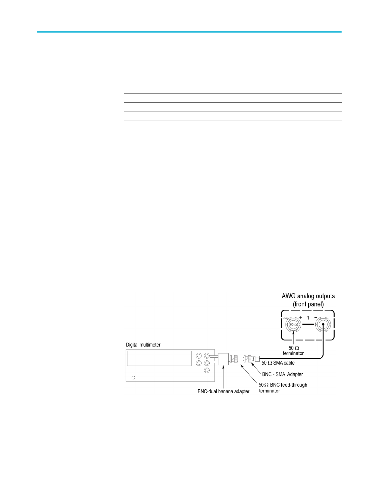
Performance tests
9. Set the Offset o
f the AWG as shown in the first row of the following table.
(See Table 36.)
Table 36: Offset accuracy
Offset settings Accuracy limits
2V 1.95Vto2.05V
0 V –10 mV to 10 mV
–2 V –2.05 V to –1.95 V
10. Press the Play button, or click Play on the display.
11. Measure the output voltage on the digital multimeter and note the value as
Measured_voltage.
12. Use the following formula to compensate the voltage for the 50 Ω BNC
feed-through terminator:
V = [(Term_R + 50) / (2×Term_R)] × Measured_voltage
Where Term_R is the resistance of the 50 Ω BNC feed-through terminator.
(See page 44, Termination resistance measurement.) procedure.
13. Verify that the voltage V falls within the limits given in the table. (See
Table 36 on page 53.)
14. Repeat steps 9 through 13 for each offset setting in the table. (See Table 36
on page 53.)
15. Press the AWG front panel All Outputs Off button (or click All Outputs Off
on the Home screen) to disable the outputs (front panel
light on).
16. Move the SMA cable from the CH 1 (+) connector to the CH 1 (–) connector
and move the 50 Ω SMA terminator from the CH 1 (–) connector to the CH
1(+)connector.
17. Press the AWG front panel All Outputs Off button (or click All Outputs Off
on the Home screen) to enable the outputs (front panel light off).
AWG5200 Series Technical Reference 53
Page 66
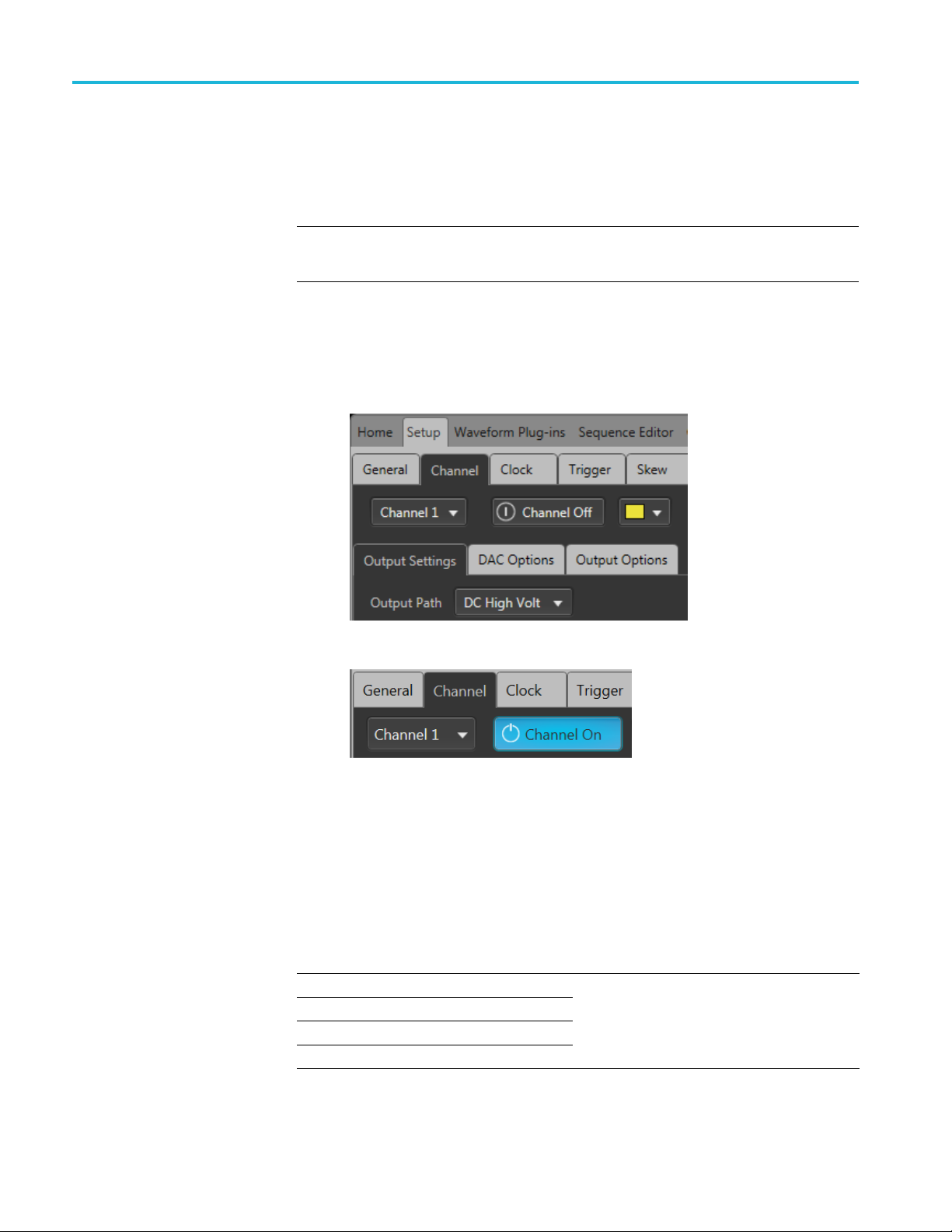
Performance tests
18. Repeat steps 9 t
hrough 14 for the (–) output.
19. Repeat steps 3 through 18 until all channels are checked, modifying the
instructions for the channel under test.
NOTE. This is the start of testing the optional DC High Volt output path.
If option HV is licensed, continue with this procedure. If not, skip to step 22.
20. Click the Setup -> Channel tab and click the Output Settings tab.
a. Select Channel 1.
b. Set the Output Path to DC High Volt.
c. Enable the Channel 1 output.
21. Repeat steps 9 through 19 for the DC High Volt path.
22. Press the AWG front panel All Outputs Off button (or click All Outputs Off
on the Home screen) to disable the outputs (front panel light on).
23. Disconnect the test setup.
Analog DC Bias accuracy (AC output paths)
Required equipment Prerequisites
Digital multimeter
BNC-dual banana adapter
SMA female-BNC male adapter
50 Ω SMA terminator
AWG preparation and load test
waveforms(See page 42, Prerequisites.)
Termination resistance measurement
procedure
54 AWG5200 Series Technical Reference
Page 67

Performance tests
Before startin
calculations. (See page 44, Termination resistance measurement.)
1. Click the Reset to Default Setup button in the toolbar
2. Press the AWG front panel All Outputs Off button (or click All Outputs Off
on the Home screen) to disable the outputs (front panel light on).
3. Connect the CH 1 (+) c onnector from the AWG to the HI and LO inputs of
the digital multimeter. Use a 50 Ω SMA cable, a BNC-SMA adapter, and
a BNC dual banana adapter.
4. Terminate the CH 1 (–) connector on the AWG using a 50 Ω SMA terminator.
g this procedure, ensure you have the “Term R” value used in the
.
5. Press the AWG front panel All Outputs Off button (or click All Outputs Off
on the Home screen) to enable the outputs (front panel light off).
6. Click the Setup -> Channel tab and click the Output Settings tab.
a. Select Channel 1.
b. Set the Output Path to AC Direct.
c. Enable the Channel 1 output.
AWG5200 Series Technical Reference 55
Page 68

Performance tests
7. Set the DC Bias of the AWG as shown in the first row of the following table.
(See Table 37.)
Table 37: Analog DC bias accuracy
Bias settings Accuracy limits
5 V 4.88 V to 5.12 V
0 V –20 mV to 20
–5 V –5.12 V to –4.88 V
mV
8. Measure the output voltage on the digital multimeter and note the value as
V_1.
9. Press the front panel All Outputs Off button (or click All Outputs Off on the
Home scr
een) to disable the outputs (front panel light on).
10. Measure the output voltage on the digital multimeter and note the value as
V_2 (DM
M residual voltage).
11. Verify that the voltage difference (V_1 – V_2) falls within the limits given in
ble. (See Table 37 on page 56.)
the ta
12. Repeat steps 7 through 11 for each bias setting in the table. (See Table 37
ge 56.)
on pa
13. Repeat steps 3 through 12 until all channels are checked, modifying the
tructions for the channel number under test.
ins
NOTE. This is the start of testing the optional AC Amplified output path.
option AC is licensed, continue with this procedure. If not, skip to step 17.
If
14. Click the Setup -> Channel tab and click the Output Settings tab.
a. Select Channel 1.
b. Set the Output Path to AC Amplified.
56 AWG5200 Series Technical Reference
Page 69

Performance tests
15. Repeat steps 7 through 13 until all channels are checked, modifying the
instructi
16. Press the AWG front panel All Outputs Off button (or click All Outputs Off
on the Hom
17. Disconnect the test setup.
ons for the channel number under test.
escreen)todisable the outputs (front panel light on).
AWG5200 Series Technical Reference 57
Page 70

Performance tests
Marker high and low level accuracy
Required equipment Prerequisites
Digital multimeter
BNC-dual banana adapter
50 Ω BNC cable
50 Ω BNC feed-through terminator
SMA male-BNC female adapter
50 Ω SMA terminator (three)
(See page 42, Prerequisites.)
Termination resistance measurement
procedure
Marker high level accuracy
Before s
tarting this procedure, ensure you have the “Term R” value used in the
calculations. (See page 44, Termination resistance measurement.)
1. Click the Reset to Default Setup button in the toolbar
.
2. Load the test waveform PV_DC_Plus.wfmx into the Waveform List.
NOTE. Test waveforms are located at
C:\Program Files\Tektronix\AWG5200\Samples\PV.
3. From the Waveform List window, assign the waveform PV_DC_Plus.wfmx
to Channel 1.
4. Press the AWG front panel All Outputs Off button (or click All Outputs Off
on the Home screen) to disable the outputs (front panel light on).
5. Connect the AWG’s CH1:1 marker connector to the HI and LO inputs on the
digital multimeter. Use a 50 Ω SMA cable, a BNC-SMA adapter, a 50 Ω BNC
feed-through terminator, and a B NC-Banana adapter.
6. Terminate the AWG’s CH1:2 through CH1:4 markers using 50 Ω SMA
terminators.
58 AWG5200 Series Technical Reference
Page 71

Performance tests
7. In the Setup -> Channel tab, select Output Settings and set the Channel 1
Resolution to 12+4 Mkrs.
8. Press the AWG front panel All Outputs Off button (or click All Outputs Off
on the Home screen) to enable the outputs (front panel light off).
9. Enable the Channel 1 output.
10. In the Setup -> Channel tab, select Output Settings and set the Channel 1
Marker High Level setting as shown in the first row of the following table.
(See Table 38.)
AWG5200 Series Technical Reference 59
Page 72

Performance tests
Table 38: Marke
High level set
+ 1.75 V 1.55 V to 1.95 V
0.0 V –25 mV to +25 mV
–0.3 V –0.355 V to –0
r high level accuracy
tings
Accuracy limi
ts
.245 V
11. Measure the output voltage on the digital multimeter and note the value as
Measured_voltage_1.
12. Use the following formula to compensate the voltage for the 50 Ω BNC
feed-through terminator:
Marker_High = (Term_R + 50) / (2 Term_R) Measured_voltage_1
Where Ter
m_R is the resistance of the 50 Ω BNC feed-thought terminator.
(See page 44, Termination resistance measurement.) procedure.
13. Verify t
hat the Marker_High level falls within the limits given in the table.
(SeeTable38onpage60.)
14. Repeat
steps 10 through 13 for the remaining rows in the table. (See Table 38
on page 60.)
15. Repea
t steps 5 through 13 for each CH1 marker (markers CH1:2 through
CH1:4), always terminating the unused markers for the channel under test.
rker low level accuracy
Ma
16. Repe
at steps 5 through 15 until all channels are checked, modifying the
instructions with the channel number under test.
17. Pres
s the AWG front panel All Outputs Off button (or click All Outputs Off
on the Home screen) to disable the outputs (front panel light on).
NOTE. This is a continuation of the procedure Marker high level accuracy check.
18. Load the test waveform PV_DC_Minus.wfmx into the Waveform List.
NOTE. Test waveforms are located at
C:\Program Files\Tektronix\AWG5200\Samples\PV.
19. From the Waveform List window, assign the waveform PV_DC_Minus.wfmx
to Channel 1.
20. Connect the AWG’s CH1:1 marker connector to the HI and LO inputs on the
digital multimeter. Use a 50 Ω SMA cable, a BNC-SMA adapter, a 50 Ω BNC
feed-through terminator, and a B NC-Banana adapter.
60 AWG5200 Series Technical Reference
Page 73

Performance tests
21. Terminate the A
WG’s CH1:2 through CH1:4 markers using 50 Ω SMA
terminators.
22. Press the front panel All Outputs Off button (or click All Outputs Off on the
Home screen) to enable the outputs (front panel light off).
23. Enable the Channel 1 output.
24. In the Setup -> Channel tab, select Output Settings and set the Channel 1
Marker Low Level setting as shown in the first row of the following table.
(See Table 39.)
Table 39: Marker low level accuracy
Low level settings Accuracy limits
+1.55V 1.37Vto1.73V
0.0 V –25 mV to +25 mV
–0.5 V –0.575 V to –0.425 V
25. Measure the output voltage on the digital multimeter and note the value as
Measured_voltage_2.
26. Use the following formula to compensate the voltage for the 50 Ω BNC
feed-through terminator:
Marker_Low = (Term_R + 50) / (2 Term_R) Measured_voltage_2
AWG5200 Series Technical Reference 61
Page 74

Performance tests
Where Term_R is
(See page 44, Termination resistance measurement.) procedure.
27. Verify that th
(SeeTable39onpage61.)
28. Repeat step
on page 61.)
29. Repeat step
CH1:4), always terminating the unused markers for the channel under test.
30. Repeat ste
instructions with the channel number under test.
31. Press the
on the Home screen) to disable the outputs (front panel light on).
ps 20 through 29 until all channels are checked, modifying the
AWG front panel All Outputs Off button (or click All Outputs Off
the resistance of the 50 Ω BNC feed-through terminator.
e Marker Low level falls within the limits given in the table.
s 24 through 27 for the remaining rows in the table. (See Table 39
s 20 through 28 for each CH1 marker (markers CH1:2 through
62 AWG5200 Series Technical Reference
Page 75

Performance tests
10 MHz referen
ce frequency accuracy
Required equipment Prerequisites
Frequency counter
SMA female-to-BNC male adapter
50 Ω SMA cable
1. Click the Reset to Default Setup button in the toolbar .
2. Connect the 10 MHz Reference Output on the rear of the AWG to the input of
the Frequency Counter. Use a 50 Ω SMA cable and a BNC-SMA adapter.
(See page 42, Prerequisites.)
3. On the F
4. Verify that the frequency counter reading falls within the range of
9.999
5. Disconnect the test setup.
requency Counter, press the Meas and the Freq buttons.
98 MHz to 10.00002 MHz.
AWG5200 Series Technical Reference 63
Page 76

Performance tests
Test record
Photocopy the test record pages and use them to record the performance test
results for your AWG.
AWG5200 series performance test record
AWG Model:
AWG Serial N umber: Certificate Number:
Temperature:
Date of Calibration:
Performance test Minimum Test result Maximum
Analog Amplitude Accuracy
DC High BW Output Path (Std, Opt DC)
AWG5202, AWG5204, AWG5208
Ch1+
Amplitude
25 mV
p-p
100 mV
200 mV
500 mV
750 mV
1V
p-p
1.5 V
p-p
Ch2+
Amplitude
25 mV
p-p
100 mV
200 mV
500 mV
750 mV
1V
p-p
1.5 V
p-p
AWG5204, AWG5208
Ch3+
Amplitude
25 mV
p-p
100 mV
200 mV
500 mV
750 mV
1V
p-p
1.5 V
p-p
p-p
p-p
p-p
p-p
p-p
p-p
p-p
p-p
p-p
p-p
p-p
p-p
RH %:
Technician:
23.75 mV 26.25 mV
98 mV 102 mV
196 mV 204 mV
490 mV 510 mV
735 mV 765 mV
980 mV 1.02 V
1.47 V 1.53 V
23.75 mV 26.25 mV
98 mV 102 mV
196 mV 204 mV
490 mV 510 mV
735 mV 765 mV
980 mV 1.02 V
1.47 V 1.53 V
23.75 mV 26.25 mV
98 mV 102 mV
196 mV 204 mV
490 mV 510 mV
735 mV 765 mV
980 mV 1.02 V
1.47 V 1.53 V
64 AWG5200 Series Technical Reference
Page 77

Performance tests
Performance test Minimum Test result Maximum
Ch4+
AWG5208
Ch5+
Ch6+
Ch 7+
Amplitude
25 mV
p-p
100 mV
200 mV
500 mV
750 mV
1V
p-p
1.5 V
p-p
Amplitude
25 mV
p-p
100 mV
200 mV
500 mV
750 mV
1V
p-p
1.5 V
p-p
Amplitude
25 mV
p-p
100 mV
200 mV
500 mV
V
750 m
1V
p-p
1.5 V
p-p
litude
Amp
25 mV
p-p
100 mV
0mV
20
500 mV
750 mV
V
1
p-p
1.5 V
p-p
23.75 mV 26.25 mV
p-p
p-p
p-p
p-p
98 mV 102 mV
196 mV 204 mV
490 mV 510 mV
735 mV 765 mV
980 mV 1.02 V
1.47 V 1.53 V
23.75 mV 26.25 mV
p-p
p-p
p-p
p-p
98 mV 102 mV
196 mV 204 mV
490 mV 510 mV
735 mV 765 mV
980 mV 1.02 V
1.47 V 1.53 V
23.75 mV 26.25 mV
p-p
p-p
p-p
p-p
98 mV 102 mV
196 mV 204 mV
490 mV 510 mV
V
735 m
765 m
V
980 mV 1.02 V
1.47 V 1.53 V
23.75 mV 26.25 mV
p-p
p-p
p-p
p-p
98 mV 102 mV
19
6mV
20
4mV
490 mV 510 mV
735 mV 765 mV
80 mV
9
.02 V
1
1.47 V 1.53 V
AWG5200 Series Technical Reference 65
Page 78

Performance tests
Performance test Minimum Test result Maximum
Ch8+
AWG5202, AWG5204, AWG5208
Ch1–
Ch2–
AWG5204, AWG5208
Ch3–
Amplitude
25 mV
p-p
100 mV
p-p
200 mV
p-p
500 mV
p-p
750 mV
p-p
1V
p-p
1.5 V
p-p
Amplitude
25 mV
p-p
100 mV
p-p
200 mV
p-p
500 mV
p-p
750 mV
p-p
1V
p-p
1.5 V
p-p
Amplitude
25 mV
p-p
100 mV
p-p
200 mV
p-p
500 mV
p-p
V
750 m
p-p
1V
p-p
1.5 V
p-p
plitude
Am
25 mV
p-p
100 mV
p-p
00 mV
2
p-p
500 mV
p-p
750 mV
p-p
1V
p-p
1.5 V
p-p
23.75 mV 26.25 mV
98 mV 102 mV
196 mV 204 mV
490 mV 510 mV
735 mV 765 mV
980 mV 1.02 V
1.47 V 1.53 V
23.75 mV 26.25 mV
98 mV 102 mV
196 mV 204 mV
490 mV 510 mV
735 mV 765 mV
980 mV 1.02 V
1.47 V 1.53 V
23.75 mV 26.25 mV
98 mV 102 mV
196 mV 204 mV
490 mV 510 mV
735 m
V
765 m
V
980 mV 1.02 V
1.47 V 1.53 V
23.75 mV 26.25 mV
98 mV 102 mV
96 mV
1
04 mV
2
490 mV 510 mV
735 mV 765 mV
980 mV 1.02 V
1.47 V 1.53 V
66 AWG5200 Series Technical Reference
Page 79

Performance tests
Performance test Minimum Test result Maximum
Ch4–
AWG5208
Ch5–
Ch6–
Ch 7–
Amplitude
25 mV
p-p
100 mV
200 mV
500 mV
750 mV
1V
p-p
1.5 V
p-p
Amplitude
25 mV
p-p
100 mV
200 mV
500 mV
750 mV
1V
p-p
1.5 V
p-p
Amplitude
25 mV
p-p
100 mV
200 mV
500 mV
V
750 m
1V
p-p
1.5 V
p-p
litude
Amp
25 mV
p-p
100 mV
0mV
20
500 mV
750 mV
V
1
p-p
1.5 V
p-p
23.75 mV 26.25 mV
p-p
p-p
p-p
p-p
98 mV 102 mV
196 mV 204 mV
490 mV 510 mV
735 mV 765 mV
980 mV 1.02 V
1.47 V 1.53 V
23.75 mV 26.25 mV
p-p
p-p
p-p
p-p
98 mV 102 mV
196 mV 204 mV
490 mV 510 mV
735 mV 765 mV
980 mV 1.02 V
1.47 V 1.53 V
23.75 mV 26.25 mV
p-p
p-p
p-p
p-p
98 mV 102 mV
196 mV 204 mV
490 mV 510 mV
V
735 m
765 m
V
980 mV 1.02 V
1.47 V 1.53 V
23.75 mV 26.25 mV
p-p
p-p
p-p
p-p
98 mV 102 mV
19
6mV
20
4mV
490 mV 510 mV
735 mV 765 mV
80 mV
9
.02 V
1
1.47 V 1.53 V
AWG5200 Series Technical Reference 67
Page 80

Performance tests
Performance test Minimum Test result Maximum
Ch8–
Amplitude
25 mV
p-p
100 mV
p-p
200 mV
p-p
500 mV
p-p
750 mV
p-p
1V
p-p
1.5 V
p-p
23.75 mV 26.25 mV
98 mV 102 mV
196 mV 204 mV
490 mV 510 mV
735 mV 765 mV
980 mV 1.02 V
1.47 V 1.53 V
68 AWG5200 Series Technical Reference
Page 81

Performance tests
Performance Test Minimum Test result Maximum
Ch1+
Ch2+
Ch3+
Ch4+
Ch5+
h6+
C
ude Accuracy
, AWG5208
Amplitude
10 mV
p-p
100 mV
500 mV
5V
p-p
Amplitude
10 mV
p-p
100 mV
500 mV
5V
p-p
Amplitude
10 mV
p-p
100 mV
500 mV
5V
p-p
tude
Ampli
10 mV
p-p
100 mV
V
500 m
5V
p-p
Amplitude
mV
10
p-p
100 mV
500 mV
V
5
p-p
Amplitude
10 mV
p-p
100 mV
500 mV
5V
p-p
9.5 mV 10.5 mV
p-p
p-p
95 mV 105 mV
490 mV 510 mV
4.90 V 5.10 V
9.5 mV 10.5 mV
p-p
p-p
95 mV 105 mV
490 mV 510 mV
4.90 V 5.10 V
9.5 mV 10.5 mV
p-p
p-p
95 mV 105 mV
490 mV 510 mV
4.90 V 5.10 V
9.5 mV 10.5 mV
p-p
p-p
95 mV 105 mV
V
490 m
510 m
V
4.90 V 5.10 V
5mV
9.
p-p
p-p
95 mV 105 mV
490 mV 510 mV
.90 V
4
10
.10 V
5
.5 mV
9.5 mV 10.5 mV
p-p
p-p
95 mV 105 mV
490 mV 510 mV
4.90 V 5.10 V
Analog Amplit
High Volt Output Path
AWG5202, AWG5204, AWG5208
AWG5204
AWG5208
AWG5200 Series Technical Reference 69
Page 82

Performance tests
Performance Test Minimum Test result Maximum
Ch7+
Ch8+
AWG5202,
AWG5204, AWG5208
Ch1–
Ch2–
AWG5204, AWG5208
Ch3–
4–
Ch
AWG5208
Ch5–
Amplitude
10 mV
p-p
100 mV
p-p
500 mV
p-p
5V
p-p
Amplitude
10 mV
p-p
100 mV
p-p
500 mV
p-p
5V
p-p
Amplitude
10 mV
p-p
100 mV
p-p
500 mV
p-p
5V
p-p
ude
Amplit
10 mV
p-p
100 mV
p-p
500 mV
p-p
5V
p-p
Amplitude
V
10 m
p-p
100 mV
p-p
500 mV
p-p
5V
p-p
Amplitude
10 mV
p-p
00 mV
1
p-p
500 mV
p-p
5V
p-p
Amplitude
10 mV
p-p
100 mV
p-p
500 mV
p-p
5V
p-p
9.5 mV 10.5 mV
95 mV 105 mV
490 mV 510 mV
4.90 V 5.10 V
9.5 mV 10.5 mV
95 mV 105 mV
490 mV 510 mV
4.90 V 5.10 V
9.5 mV 10.5 mV
95 mV 105 mV
490 mV 510 mV
4.90 V 5.10 V
9.5 mV 10.5 mV
95 mV 105 mV
490 mV 510 mV
4.90 V 5.10 V
9.5
mV
10.
5mV
95 mV 105 mV
490 mV 510 mV
4.
90 V
5.
10 V
9.5 mV 10.5 mV
5mV
9
05 mV
1
490 mV 510 mV
4.90 V 5.10 V
9.5 mV 10.5 mV
95 mV 105 mV
490 mV 510 mV
4.95 V 5.10 V
70 AWG5200 Series Technical Reference
Page 83

Performance tests
Performance Test Minimum Test result Maximum
Ch6–
Ch7–
Ch8–
Amplitude
10 mV
p-p
100 mV
500 mV
5V
p-p
Amplitude
10 mV
p-p
100 mV
500 mV
5V
p-p
Amplitude
10 mV
p-p
100 mV
500 mV
5V
p-p
9.5 mV 10.5 mV
p-p
p-p
95 mV 105 mV
490 mV 510 mV
4.90 V 5.10 V
9.5 mV 10.5 mV
p-p
p-p
95 mV 105 mV
490 mV 510 mV
4.90 V 5.10 V
9.5 mV 10.5 mV
p-p
p-p
95 mV 105 mV
490 mV 510 mV
4.90 V 5.10 V
AWG5200 Series Technical Reference 71
Page 84

Performance tests
Performance Test Minimum Test result Maximum
Analog Offset A ccuracy
(DC High BW Output Path)
AWG5202, AWG5204, AWG5208
Ch1+
Ch2+
AWG5204, AWG5208
Ch3+
Ch4+
AWG5208
Ch5+
Ch6+
Ch7+
Ch8+
Offset
2 V 1.95 V 2.05 V
0 V –10 mV 10 mV
–2 V –2.05 V –1.95 V
Offset
2 V 1.95 V 2.05 V
0 V –10 mV 10 mV
–2 V –2.05 V –1.95 V
Offset
2 V 1.95 V 2.05 V
0 V –10 mV 10 mV
–2 V –2.05 V –1.95 V
Offset
2 V 1.95 V 2.05 V
0mV
V
10 mV
mV
10
0 V –10 m
–2 V –2.05 V –1.95 V
Offset
2 V 1.95 V 2.05 V
0V –1
–2 V –2.05 V –1.95 V
Offset
2 V 1.95 V 2.05 V
0 V –10 mV 10 mV
–2 V –2.05 V –1.95 V
Offset
2 V 1.95 V 2.05 V
0 V –10 mV 10 mV
–2 V –2.05 V –1.95 V
Offset
2 V 1.95 V 2.05 V
0 V –10 mV 10 mV
–2 V –2.05 V –1.95 V
72 AWG5200 Series Technical Reference
Page 85

Performance tests
Performance Test Minimum Test result Maximum
AWG5202, AWG5204, AWG5208
Ch1–
Ch2–
AWG5204, AWG5208
Ch3–
Ch4–
AWG5208
Ch5–
Ch6–
Ch7–
Ch8–
Offset
2 V 1.95 V 2.05 V
0 V –10 mV 10 mV
–2 V –2.05 V –1.95 V
Offset
2 V 1.95 V 2.05 V
0 V –10 mV 10 mV
–2 V –2.05 V –1.95 V
Offset
2 V 1.95 V 2.05 V
0 V –10 mV 10 mV
–2 V –2.05 V –1.95 V
Offset
2 V 1.95 V 2.05 V
0 V –10 mV 10 mV
–2 V –2.05 V –1.95 V
Offset
.95 V
1
5V
2V 1.9
0 V –10 mV 10 mV
–2 V –2.05 V –1.95 V
Offset
V
2
0 V –10 mV 10 mV
–2 V –2.05 V –1.95 V
Offset
2 V 1.95 V 2.05 V
0 V –10 mV 10 mV
–2 V –2.05 V –1.95 V
Offset
2 V 1.95 V 2.05 V
0 V –10 mV 10 mV
–2 V –2.05 V –1.95 V
2.0
.05 V
2
5V
AWG5200 Series Technical Reference 73
Page 86

Performance tests
Performance Test Minimum Test result Maximum
Analog Offset A ccuracy
(DC High Volt Output Path)
AWG5202, AWG5204, AWG5208
Ch1+
Ch2+
AWG5204, AWG5208
Ch3+
Ch4+
AWG5208
Ch5+
Ch6+
Ch7+
Ch8+
Offset
2 V 1.95 V 2.05 V
0 V –10 mV 10 mV
–2 V –2.05 V –1.95 V
Offset
2 V 1.95 V 2.05 V
0 V –10 mV 10 mV
–2 V –2.05 V –1.95 V
Offset
2 V 1.95 V 2.05 V
0 V –10 mV 10 mV
–2 V –2.05 V –1.95 V
Offset
2 V 1.95 V 2.05 V
0mV
V
10 mV
mV
10
0 V –10 m
–2 V –2.05 V –1.95 V
Offset
2 V 1.95 V 2.05 V
0V –1
–2 V –2.05 V –1.95 V
Offset
2 V 1.95 V 2.05 V
0 V –10 mV 10 mV
–2 V –2.05 V –1.95 V
Offset
2 V 1.95 V 2.05 V
0 V –10 mV 10 mV
–2 V –2.05 V –1.95 V
Offset
2 V 1.95 V 2.05 V
0 V –10 mV 10 mV
–2 V –2.05 V –1.95 V
74 AWG5200 Series Technical Reference
Page 87

Performance tests
Performance Test Minimum Test result Maximum
AWG5202, AWG5204, AWG5208
Ch1–
Ch2–
AWG5204, AWG5208
Ch3–
Ch4–
AWG5208
Ch5–
Ch6–
Ch7–
Ch8–
Offset
2 V 1.95 V 2.05 V
0 V –10 mV 10 mV
–2 V –2.05 V –1.95 V
Offset
2 V 1.95 V 2.05 V
0 V –10 mV 10 mV
–2 V –2.05 V –1.95 V
Offset
2 V 1.95 V 2.05 V
0 V –10 mV 10 mV
–2 V –2.05 V –1.95 V
Offset
2 V 1.95 V 2.05 V
0 V –10 mV 10 mV
–2 V –2.05 V –1.95 V
Offset
.95 V
1
5V
2V 1.9
0 V –10 mV 10 mV
–2 V –2.05 V –1.95 V
Offset
V
2
0 V –10 mV 10 mV
–2 V –2.05 V –1.95 V
Offset
2 V 1.95 V 2.05 V
0 V –10 mV 10 mV
–2 V –2.05 V –1.95 V
Offset
2 V 1.95 V 2.05 V
0 V –10 mV 10 mV
–2 V –2.05 V –1.95 V
2.0
.05 V
2
5V
AWG5200 Series Technical Reference 75
Page 88

Performance tests
Performance test Minimum Test result Maximum
Analog DC Bias Accuracy
(AC Direct Output Path)
AWG5202, AWG5204, AWG5208
Ch1+
Ch2+
AWG5204, AWG5208
Ch3+
Ch4+
AWG5208
Ch5+
Ch6+
Ch7+
Ch8+
DC Bias
5 V 4.88 V 5.12 V
0 V –20 mV 20 mV
–5 V –5.12 V –4.88 V
DC Bias
5 V 4.88 V 5.12 V
0 V –20 mV 20 mV
–5 V –5.12 V –4.88 V
DC Bias
5 V 4.88 V 5.12 V
0 V –20 mV 20 mV
–5 V –5.12 V –4.88 V
DC Bias
5 V 4.88 V 5.12 V
0mV
V
20 mV
mV
20
0 V –20 m
–5 V –5.12 V –4.88 V
DC Bias
5 V 4.88 V 5.12 V
0V –2
–5 V –5.12 V –4.88 V
DC Bias
5 V 4.88 V 5.12 V
0 V –20 mV 20 mV
–5 V –5.12 V –4.88 V
DC Bias
5 V 4.88 V 5.12 V
0 V –20 mV 20 mV
–5 V –5.12 V –4.88 V
DC Bias
5 V 4.88 V 5.12 V
0 V –20 mV 20 mV
–5 V –5.12 V –4.88 V
76 AWG5200 Series Technical Reference
Page 89

Performance tests
Performance test Minimum Test result Maximum
AWG5202, AWG5204, AWG5208
Ch1–
Ch2–
AWG5204, AWG5208
Ch3–
Ch4–
AWG5208
Ch5–
Ch6–
Ch7–
Ch8–
DC Bias
5 V 4.88 V 5.12 V
0 V –20 mV 20 mV
–5 V –5.12 V –4.88 V
DC Bias
5 V 4.88 V 5.12 V
0 V –20 mV 20 mV
–5 V –5.12 V –4.88 V
DC Bias
5 V 4.88 V 5.12 V
0 V –20 mV 20 mV
–5 V –5.12 V –4.88 V
DC Bias
5 V 4.88 V 5.12 V
0 V –20 mV 20 mV
–5 V –5.12 V –4.88 V
DC Bias
.88 V
4
8V
5V 4.8
0 V –20 mV 20 mV
–5 V –5.12 V –4.88 V
DC Bias
V
5
0 V –20 mV 20 mV
–5 V –5.12 V –4.88 V
DC Bias
5 V 4.88 V 5.12 V
0 V –20 mV 20 mV
–5 V –5.12 V –4.88 V
DC Bias
5 V 4.88 V 5.12 V
0 V –20 mV 20 mV
–5 V –5.12 V –4.88 V
5.1
.12 V
5
2V
AWG5200 Series Technical Reference 77
Page 90

Performance tests
Performance test Minimum Test result Maximum
Analog DC Bias Accuracy
(AC Amplified Output Path)
AWG5202, AWG5204, AWG5208
Ch1+
Ch2+
AWG5204, AWG5208
Ch3+
Ch4+
AWG5208
Ch5+
Ch6+
Ch7+
Ch8+
DC Bias
5 V 4.88 V 5.12 V
0 V –20 mV 20 mV
–5 V –5.12 V –4.88 V
DC Bias
5 V 4.88 V 5.12 V
0 V –20 mV 20 mV
–5 V –5.12 V –4.88 V
DC Bias
5 V 4.88 V 5.12 V
0 V –20 mV 20 mV
–5 V –5.12 V –4.88 V
DC Bias
5 V 4.88 V 5.12 V
0mV
V
20 mV
mV
20
0 V –20 m
–5 V –5.12 V –4.88 V
DC Bias
5 V 4.88 V 5.12 V
0V –2
–5 V –5.12 V –4.88 V
DC Bias
5 V 4.88 V 5.12 V
0 V –20 mV 20 mV
–5 V –5.12 V –4.88 V
DC Bias
5 V 4.88 V 5.12 V
0 V –20 mV 20 mV
–5 V –5.12 V –4.88 V
DC Bias
5 V 4.88 V 5.12 V
0 V –20 mV 20 mV
–5 V –5.12 V –4.88 V
78 AWG5200 Series Technical Reference
Page 91

Performance tests
Performance test Minimum Test result Maximum
AWG5202, AWG5204, AWG5208
Ch1–
Ch2–
AWG5204, AWG5208
Ch3–
Ch4–
AWG5208
Ch5–
Ch6–
Ch7–
Ch8–
DC Bias
5 V 4.88 V 5.12 V
0 V –20 mV 20 mV
–5 V –5.12 V –4.88 V
DC Bias
5 V 4.88 V 5.12 V
0 V –20 mV 20 mV
–5 V –5.12 V –4.88 V
DC Bias
5 V 4.88 V 5.12 V
0 V –20 mV 20 mV
–5 V –5.12 V –4.88 V
DC Bias
5 V 4.88 V 5.12 V
0 V –20 mV 20 mV
–5 V –5.12 V –4.88 V
DC Bias
.88 V
4
8V
5V 4.8
0 V –20 mV 20 mV
–5 V –5.12 V –4.88 V
DC Bias
V
5
0 V –20 mV 20 mV
–5 V –5.12 V –4.88 V
DC Bias
5 V 4.88 V 5.12 V
0 V –20 mV 20 mV
–5 V –5.12 V –4.88 V
DC Bias
5 V 4.88 V 5.12 V
0 V –20 mV 20 mV
–5 V –5.12 V –4.88 V
5.1
.12 V
5
2V
AWG5200 Series Technical Reference 79
Page 92

Performance tests
Performance test Minimum Test result Maximum
Marker
High Level Accuracy
AWG5202, AWG5204, AWG5208
CH1:1
CH1:2
CH1:3
CH1:4
CH2:1
CH2:
CH2:3
CH2:4
2
+ 1.75 V 1.55 V 1.95 V
0.0 V –25 mV +25 mV
–0.3 V –0.355 V –0.245 V
+ 1.75 V 1.55 V 1.95 V
0.0 V –25 mV +25 mV
–0.3 V –0.355 V –0.245 V
+ 1.75 V 1.55 V 1.95 V
0.0 V –25 mV +25 mV
–0.3 V –0.355 V –0.245 V
+ 1.75 V 1.55 V 1.95 V
0.0 V –25 mV +25 mV
–0.3 V –0.355 V –0.245 V
+ 1.75 V 1.55 V 1.95 V
0.0 V –25 mV +25 mV
V
–0.3
+ 1.75 V 1.55 V 1.95 V
0.0 V –25 mV +25 mV
–0.3 V –0.355 V –0.245 V
75 V
+1.
0V
0.
–0.3 V –0.355 V –0.245 V
+ 1.75 V 1.55 V 1.95 V
0.0 V –25 mV +25 mV
0.3 V
–
–0.3
5V
1.5
5mV
–2
0.355 V
–
55 V
–0.2
5V
1.9
5mV
+2
0.245 V
–
45 V
80 AWG5200 Series Technical Reference
Page 93

Performance tests
Performance test Minimum Test result Maximum
AWG5204, AWG5208
CH3:1
CH3:2
CH3:3
CH3:4
CH4:1
CH4:
CH4:3
CH4:4
WG5208
A
CH5:1
CH5:2
CH5:3
CH5:4
2
+ 1.75 V 1.55 V 1.95 V
0.0 V –25 mV +25 mV
–0.3 V –0.355 V –0.245 V
+ 1.75 V 1.55 V 1.95 V
0.0 V –25 mV +25 mV
–0.3 V –0.355 V –0.245 V
+ 1.75 V 1.55 V 1.95 V
0.0 V –25 mV +25 mV
–0.3 V –0.355 V –0.245 V
+ 1.75 V 1.55 V 1.95 V
0.0 V –25 mV +25 mV
–0.3 V –0.355 V –0.245 V
+ 1.75 V 1.55 V 1.95 V
0.0 V –25 mV +25 mV
5V
1.5
–25
0.355 V
–
5V
mV
–0.3 V –0.35
+ 1.75 V 1.55 V 1.95 V
0.0 V –25 mV +25 mV
–0.3 V –0.355 V –0.245 V
75 V
+1.
V
0.0
–0.3 V –0.355 V –0.245 V
+ 1.75 V 1.55 V 1.95 V
0.0 V –25 mV +25 mV
0.3 V
–
+ 1.75 V 1.55 V 1.95 V
0.0 V –25 mV +25 mV
–0.3 V –0.355 V –0.245 V
+ 1.75 V 1.55 V 1.95 V
0.0 V –25 mV +25 mV
–0.3 V –0.355 V –0.245 V
+ 1.75 V 1.55 V 1.95 V
0.0 V –25 mV +25 mV
–0.3 V –0.355 V –0.245 V
+ 1.75 V 1.55 V 1.95 V
0.0 V –25 mV +25 mV
–0.3 V –0.355 V –0.245 V
–0.24
5V
1.9
+25
0.245 V
–
5V
mV
AWG5200 Series Technical Reference 81
Page 94

Performance tests
Performance test Minimum Test result Maximum
CH6:1
CH6:2
CH6:3
CH6:4
CH7:1
CH7:2
CH7:3
CH7:4
H8:1
C
CH8:2
CH8:3
CH8:4
+ 1.75 V 1.55 V 1.95 V
0.0 V –25 mV +25 mV
–0.3 V –0.355 V –0.245 V
+ 1.75 V 1.55 V 1.95 V
0.0 V –25 mV +25 mV
–0.3 V –0.355 V –0.245 V
+ 1.75 V 1.55 V 1.95 V
0.0 V –25 mV +25 mV
–0.3 V –0.355 V –0.245 V
+ 1.75 V 1.55 V 1.95 V
0.0 V –25 mV +25 mV
–0.3 V –0.355 V –0.245 V
+ 1.75 V 1.55 V 1.95 V
0.0 V –25 mV +25 mV
1.55
–25
–0
V
V
mV
.355 V
–0.3 V –0.355
+ 1.75 V 1.55 V 1.95 V
0.0 V –25 mV +25 mV
–0.3 V –0.355 V –0.245 V
5V
+1.7
V
0.0
–0.3 V –0.355 V –0.245 V
+ 1.75 V 1.55 V 1.95 V
0.0 V –25 mV +25 mV
.3 V
–0
+ 1.75 V 1.55 V 1.95 V
0.0 V –25 mV +25 mV
–0.3 V –0.355 V –0.245 V
+ 1.75 V 1.55 V 1.95 V
0.0 V –25 mV +25 mV
–0.3 V –0.355 V –0.245 V
+ 1.75 V 1.55 V 1.95 V
0.0 V –25 mV +25 mV
–0.3 V –0.355 V –0.2945 V
+ 1.75 V 1.55 V 1.95 V
0.0 V –25 mV 25 mV
–0.3 V –0.355 V –0.245 V
–0.245
1.95
mV
+25
.245 V
–0
V
V
82 AWG5200 Series Technical Reference
Page 95

Performance tests
Performance test Minimum Test result Maximum
Marker
Low Level Accuracy
AWG5202, AWG5204, AWG5208
CH1:1
CH1:2
CH1:3
CH1:4
CH2:1
CH2:
CH2:3
CH2:4
2
+ 1.55 V 1.37 V 1.73 V
0.0 V –25 mV 25 mV
–500 mV –0.575 V –0.425 V
+ 1.55 V 1.37 V 1.73 V
0.0 V –25 mV 25 mV
–500 mV –0.575 V –0.425 V
+ 1.55 V 1.37 V 1.73 V
0.0 V –25 mV 25 mV
–500 mV –0.575 V –0.425 V
+ 1.55 V 1.37 V 1.73 V
0.0 V –25 mV 25 mV
–500 mV –0.575 V –0.425 V
+ 1.55 V 1.37 V 1.73 V
0.0 V –25 mV 25 mV
mV
–500
+ 1.55 V 1.37 V 1.73 V
0.0 V –25 mV 25 mV
–500 mV –0.575 V –0.425 V
55 V
+1.
0V
0.
–500 mV –0.575 V –0.425 V
+ 1.55 V 1.37 V 1.73 V
0.0 V –25 mV 25 mV
500 mV
–
–0.5
7V
1.3
5mV
–2
0.575 V
–
75 V
–0.4
3V
1.7
mV
25
0.425 V
–
25 V
AWG5200 Series Technical Reference 83
Page 96

Performance tests
Performance test Minimum Test result Maximum
AWG5204, AWG5208
CH3:1
CH3:2
CH3:3
CH3:4
CH4:1
CH4:
CH4:3
CH4:4
WG5208
A
CH5:1
CH5:2
CH5:3
CH5:4
2
+ 1.55 V 1.37 V 1.73 V
0.0 V –25 mV 25 mV
–500 mV –0.5275 V –0.425 V
+ 1.55 V 1.37 V 1.73 V
0.0 V –25 mV 25 mV
–500 mV –0.575 V –0.425 V
+ 1.55 V 1.37 V 1.73 V
0.0 V –25 mV 25 mV
–500 mV –0.575 V –0.425 V
+ 1.55 V 1.37 V 1.73 V
0.0 V –25 mV 25 mV
–500 mV –0.575 V –0.425 V
+ 1.55 V 1.37 V 1.73 V
0.0 V –25 mV 25 mV
V
–500 m
+ 1.55 V 1.37 V 1.73 V
0.0 V –25 mV 25 mV
–500 mV –0.575 V –0.425 V
55 V
+1.
V
0.0
–500 mV –0.5275 V –0.425 V
+ 1.55 V 1.37 V 1.73 V
0.0 V –25 mV 25 mV
500 mV
–
+ 1.55 V 1.37 V 1.73 V
0.0 V –25 mV 25 mV
–500 mV –0.575 V –0.425 V
+ 1.55 V 1.37 V 1.73 V
0.0 V –25 mV 25 mV
–500 mV –0.575 V –0.425 V
+ 1.55 V 1.37 V 1.73 V
0.0 V –25 mV 25 mV
–500 mV –0.575 V –0.425 V
+ 1.55 V 1.37 V 1.73 V
0.0 V –25 mV 25 mV
–500 mV –0.575 V –0.425 V
–0.57
7V
1.3
–25
0.575 V
–
mV
5V
–0.42
3V
1.7
25 m
0.425 V
–
5V
V
84 AWG5200 Series Technical Reference
Page 97

Performance tests
Performance test Minimum Test result Maximum
CH6:1
CH6:2
CH6:3
CH6:4
CH7:1
CH7:2
CH7:3
CH7:4
H8:1
C
CH8:2
CH8:3
CH8:4
+ 1.55 V 1.37 V 1.73 V
0.0 V –25 mV 25 mV
–500 mV –0.575 V –0.425 V
+ 1.55 V 1.37 V 1.73 V
0.0 V –25 mV 25 mV
–500 mV –0.575 V –0.4725 V
+ 1.55 V 1.37 V 1.73 V
0.0 V –25 mV 25 mV
–500 mV –0.575 V –0.425 V
+ 1.55 V 1.37 V 1.73 V
0.0 V –25 mV 25 mV
–500 mV –0.575 V –0.425 V
+ 1.55 V 1.37 V 1.73 V
0.0 V –25 mV 25 mV
1.37
–25
–0
V
V
mV
.575 V
–500 mV –0.575
+ 1.55 V 1.37 V 1.73 V
0.0 V –25 mV 25 mV
–500 mV –0.575 V –0.425 V
5V
+1.5
V
0.0
–500 mV –0.575 V –0.425 V
+ 1.55 V 1.37 V 1.73 V
0.0 V –25 mV +25 mV
00 mV
–5
+ 1.55 V 1.37 V 1.55 V
0.0 V –25 mV 25 mV
–500 mV –0.575 V –0.425 V
+ 1.55 V 1.37 V 1.73 V
0.0 V –25 mV 25 mV
–500 mV –0.575 V –0.425 V
+ 1.55 V 1.37 V 1.73 V
0.0 V –25 mV 25 mV
–500 mV –0.575 V –0.425 V
+ 1.55 V 1.37 V 1.73 V
0.0 V –25 mV 25 mV
–500 mV –0.575 V –0.425 V
–0.425
1.73
25 m
.425 V
–0
V
V
V
AWG5200 Series Technical Reference 85
Page 98

Performance tests
Performance test Minimum Test result Maximum
10 MHz Reference Frequency Accuracy
9.99998 MHz 10.00002 MHz
86 AWG5200 Series Technical Reference
 Loading...