

Page 1

Instructions Manual
016–1675–50
AWG510 & AWG520 Rackmount Kit
ѩуЯўЦѳшȦЭуш
075-0263-50
www.tektronix.com
075026350
Page 2

Copyright © T ektronix Japan, Ltd. All rights reserved.
Copyright © T ektronix, Inc. All rights reserved.
Tektronix products are covered by U.S. and foreign patents, issued and pending. Information in this publication supercedes
that in all previously published material. Specifications and price change privileges reserved.
Tektronix Japan, Ltd., 5–9–31 Kitashinagawa, Shinagawa–ku, Tokyo 141–0001 Japan
Tektronix, Inc., P.O. Box 500, Beaverton, OR 97077
TEKTRONIX and TEK are registered trademarks of T ektronix, Inc.
Page 3

WARRANTY
Tektronix warrants that this product will be free from defects in materials and workmanship for a period of three (3) years from
the date of shipment. If any such product proves defective during this warranty period, Tektronix, at its option, either will repair
the defective product without charge for parts and labor, or will provide a replacement in exchange for the defective product.
In order to obtain service under this warranty, Customer must notify Tektronix of the defect before the expiration of the warranty
period and make suitable arrangements for the performance of service. Customer shall be responsible for packaging and
shipping the defective product to the service center designated by Tektronix, with shipping charges prepaid. Tektronix shall
pay for the return of the product to Customer if the shipment is to a location within the country in which the Tektronix service
center is located. Customer shall be responsible for paying all shipping charges, duties, taxes, and any other charges for
products returned to any other locations.
This warranty shall not apply to any defect, failure or damage caused by improper use or improper or inadequate maintenance
and care. Tektronix shall not be obligated to furnish service under this warranty a) to repair damage resulting from attempts by
personnel other than Tektronix representatives to install, repair or service the product; b) to repair damage resulting from
improper use or connection to incompatible equipment; or c) to service a product that has been modified or integrated with
other products when the effect of such modification or integration increases the time or difficulty of servicing the product.
THIS WARRANTY IS GIVEN BY TEKTRONIX WITH RESPECT TO THIS PRODUCT IN LIEU OF ANY OTHER
WARRANTIES, EXPRESS OR IMPLIED. TEKTRONIX AND ITS VENDORS DISCLAIM ANY IMPLIED WARRANTIES OF
MERCHANTABILITY OR FITNESS FOR A PARTICULAR PURPOSE. TEKTRONIX' RESPONSIBILITY TO REPAIR OR
REPLACE DEFECTIVE PRODUCTS IS THE SOLE AND EXCLUSIVE REMEDY PROVIDED TO THE CUSTOMER FOR
BREACH OF THIS WARRANTY. TEKTRONIX AND ITS VENDORS WILL NOT BE LIABLE FOR ANY INDIRECT, SPECIAL,
INCIDENTAL, OR CONSEQUENTIAL DAMAGES IRRESPECTIVE OF WHETHER TEKTRONIX OR THE VENDOR HAS
ADVANCE NOTICE OF THE POSSIBILITY OF SUCH DAMAGES.
Page 4

Page 5

Table of Contents
List of Figures
General Safety Summary iii. . . . . . . . . . . . . . . . . . . . . . . . . . . . . . . . . . . .
General Information 1. . . . . . . . . . . . . . . . . . . . . . . . . . . . . . . . . . . . . . . .
Rack-Adapter Kit Description 1. . . . . . . . . . . . . . . . . . . . . . . . . . . . . . . . . .
Clearance Requirements 3. . . . . . . . . . . . . . . . . . . . . . . . . . . . . . . . . . . . . .
Installation Instructions 5. . . . . . . . . . . . . . . . . . . . . . . . . . . . . . . . . . . . .
Equipment List 5. . . . . . . . . . . . . . . . . . . . . . . . . . . . . . . . . . . . . . . . . . . . .
General Instructions 6. . . . . . . . . . . . . . . . . . . . . . . . . . . . . . . . . . . . . . . . . .
Install the Rack Adapter Kit 7. . . . . . . . . . . . . . . . . . . . . . . . . . . . . . . . . . .
Rackmount the Rack-Adapted AWG500 14. . . . . . . . . . . . . . . . . . . . . . . . .
Replaceable Mechanical Parts 19. . . . . . . . . . . . . . . . . . . . . . . . . . . . . . . .
Figure 1: AWG500 cooling 2. . . . . . . . . . . . . . . . . . . . . . . . . . . . . . . . . . .
Figure 2: AWG500 with Rack Adapter Installed 4. . . . . . . . . . . . . . . . .
Figure 3: Trim Ring Removal 8. . . . . . . . . . . . . . . . . . . . . . . . . . . . . . . . .
Figure 4: Cabinet Hardware Removal 9. . . . . . . . . . . . . . . . . . . . . . . . .
Figure 5: Installation of Kit Hardware to Oscilloscope 11. . . . . . . . . . . .
Figure 6: Left and Right Inside Track Identification 13. . . . . . . . . . . . . .
Figure 7: Assembly of Slide-Out Track Assemblies 15. . . . . . . . . . . . . . .
Figure 8: Vertical Clearances for Rack Installation (Left-Front
Rail Shown) 16. . . . . . . . . . . . . . . . . . . . . . . . . . . . . . . . . . . . . . . . . . . .
Figure 9: Installation of Slide-out Track Assemblies in
Rack (Top View) 17. . . . . . . . . . . . . . . . . . . . . . . . . . . . . . . . . . . . . . . .
Figure 10: Exploded View 23. . . . . . . . . . . . . . . . . . . . . . . . . . . . . . . . . . . .
AWG510 and AWG520 Rackmount Instructions
i
Page 6

Table of Contents
List of Tables
Table 1: Warranted characteristics 2. . . . . . . . . . . . . . . . . . . . . . . . . . . .
Table 2: Tools required for rackmount installation 5. . . . . . . . . . . . . .
ii
AWG510 and AWG520 Rackmount Instructions
Page 7

General Safety Summary
Review the following safety precautions to avoid injury and prevent damage to
this product or any products connected to it. To avoid potential hazards, use this
product only as specified.
Only qualified personnel should perform service procedures.
To Avoid Fire or
Personal Injury
Use Proper Power Cord. Use only the power cord specified for this product and
certified for the country of use.
Connect and Disconnect Properly. Do not connect or disconnect probes or test
leads while they are connected to a voltage source.
Ground the Product. This product is grounded through the grounding conductor
of the power cord. To avoid electric shock, the grounding conductor must be
connected to earth ground. Before making connections to the input or output
terminals of the product, ensure that the product is properly grounded.
Observe All Terminal Ratings. To avoid fire or shock hazard, observe all ratings
and markings on the product. Consult the product manual for further ratings
information before making connections to the product.
Do Not Operate Without Covers. Do not operate this product with covers or panels
removed.
Use Proper Fuse. Use only the fuse type and rating specified for this product.
Avoid Exposed Circuitry. Do not touch exposed connections and components
when power is present.
Do Not Operate With Suspected Failures. If you suspect there is damage to this
product, have it inspected by qualified service personnel.
Do Not Operate in Wet/Damp Conditions.
Do Not Operate in an Explosive Atmosphere.
Provide Proper Ventilation. Refer to the manual’s installation instructions for
details on installing the product so it has proper ventilation.
AWG510 and AWG520 Rackmount Instructions
iii
Page 8
General Safety Summary
Symbols and Terms
Terms in this Manual. These terms may appear in this manual:
WARNING. Warning statements identify conditions or practices that could result
in injury or loss of life.
CAUTION. Caution statements identify conditions or practices that could result in
damage to this product or other property.
Terms on the Product. These terms may appear on the product:
DANGER indicates an injury hazard immediately accessible as you read the
marking.
WARNING indicates an injury hazard not immediately accessible as you read the
marking.
CAUTION indicates a hazard to property including the product.
Symbols on the Product. The following symbols may appear on the product:
WARNING
High Voltage
Protective Ground
(Earth) Terminal
CAUTION
Refer to Manual
Double
Insulated
iv
AWG510 and AWG520 Rackmount Instructions
Page 9

General Information
This introduction describes the AWG510 and AWG520 Arbitary Waveform
Generators Rack Adapter Kit, discusses its effects on AWG500 performance, and
lists its clearance requirements. Please read these topics before attempting to
rackmount your AWG500.
The remainder of this document refers to the AWG510 and AWG520 Arbitrary
Waveform Generators generically as AWG500.
RackĆAdapter Kit Description
The rack adapter kit is a collection of parts that, once installed, configure the
AWG500 for mounting in a standard 19-inch equipment rack.
NOTE. A standard equipment rack has rails with universal hole spacing. If you
use a rack with other than universal hole spacing, you may have to drill
additional mounting holes in the rack
Warranted Characteristics
The rack-adapter kit can be obtained in two ways:
H Customers with a standard-version AWG500 can order the kit by part
number and install it to adapt the AWG500 for rackmounting.
H Customers who purchase a new AWG500 can order it with option 1R.
Tektronix will ship option 1R AWG500 with the rack adapter kit hardware
already installed on the AWG500.
The instructions in this document cover the installation of option 1R AWG500,
as well as rack-adapting and installation of standard AWG500.
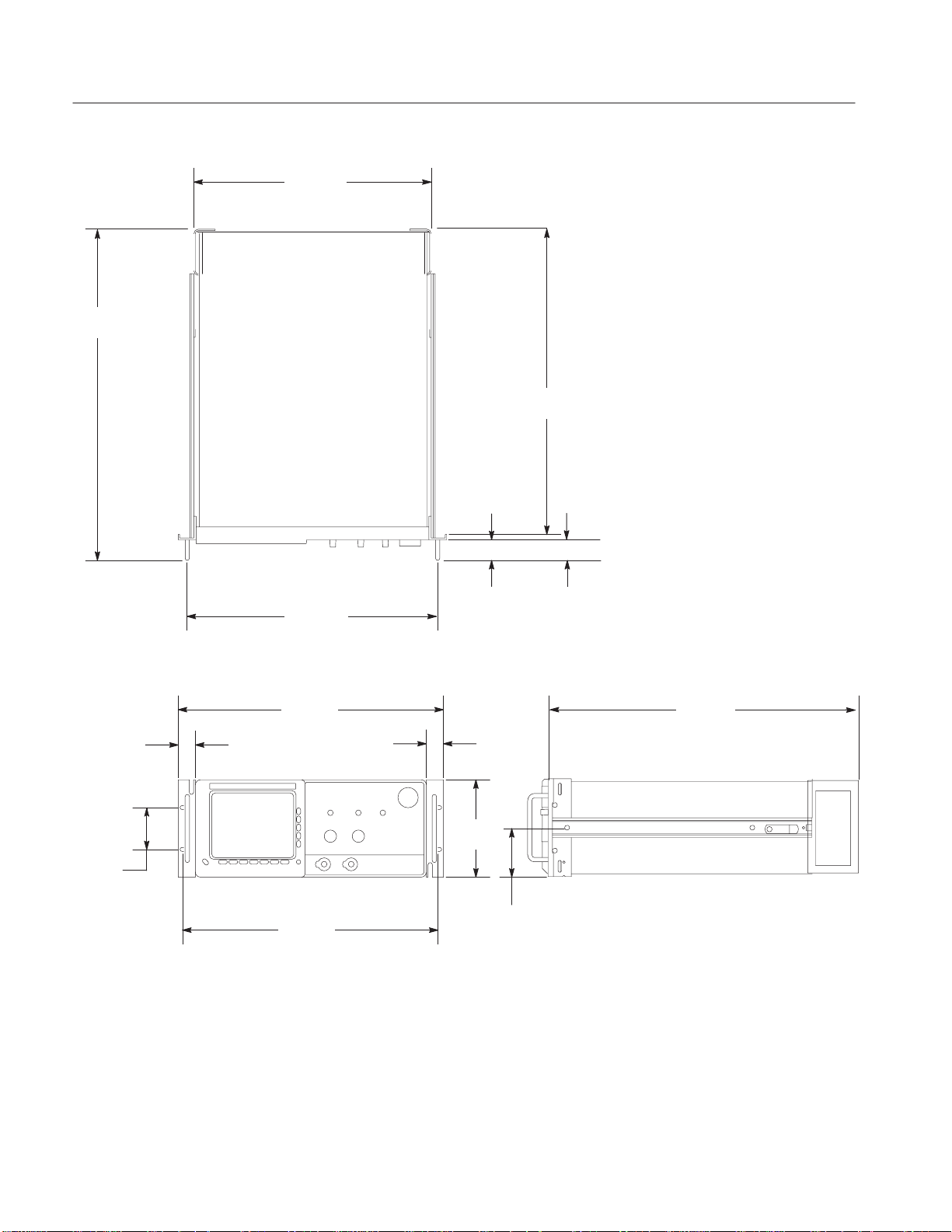
The dimensional drawing in Figure 2 on page 4 illustrates the rack-adapted
AWG500.
When the AWG500 is installed according to the instructions in this document,
the rackmounted AWG500 meets all warranted requirements except for those
listed in Environmental Requirements below. AWG500 mounted using methods
other than those described in these instructions may cause the AWG500 to not
meet its warranted requirements.
Cooling air enters on the bottom and right sides as shown in Figure 1.
AWG510 and AWG520 Rackmount Instructions
1
Page 10
General Information
Hot air out
Cool air in
Environmental
Requirements
Figure 1: AWG500 cooling
See Specification in the user or service manual that applies to your AWG500
model for tables of the warranted characteristics.
The following environmental characteristics supercede those listed in the user or
service manual for your AWG500.
Table 1: Warranted characteristics
Characteristic Description
Temperature, Operating
Inside Rack Cabinet +10ĂC_ to +40 C_
2
AWG510 and AWG520 Rackmount Instructions
Page 11
Clearance Requirements
The rack in which the rack adapted AWG500 is mounted must provide the
following clearance requirements:
H A minimum of seven inches (178 mm) of vertical space.
H A minimum width of 17 5/8 inches (448 mm) between the left- and
H A minimum inside height depth of at least 23 5/8 inches (600 mm).
WARNING. Adhering to these clearance requirements mounts the rack adapted
AWG500 with sufficient for air circulation and accommodation of the power
cord and mounting hardware. Failure to provide these clearances can result in
overheating and can cause the AWG500 to not operate properly and/or fail.
General Information
right-front rails in the rack.
AWG510 and AWG520 Rackmount Instructions
3
Page 12
General Information
23.4
(587.1)
16.8
(426.72)
21.6
(549.0)
17.7
(450.60)
19.1
(484.6)
1.2
(30.86)
3.0
(76.20)
18.4
(468)
Figure 2: AWG500 with Rack Adapter Installed
1.5
(38.1)
1.2
(30.86)
7.0
(177.2)
1.8
(46.51)
21.6
(549.0)
3.5
(88.6)
4
AWG510 and AWG520 Rackmount Instructions
Page 13

Installation Instructions
This section contains all procedures needed to rackmount the AWG500. Begin
with General Instructions, on page 6.
NOTE. Throughout this document, AWG500 are referred to as either “standard”
or “option 1R” versions. Standard versions are simply AWG500 not equipped
with option 1R. (The option-1R AWG500 are shipped from the factory already
configured for rackmounting.)
Equipment List
The following tools are required to attach the rack-adapter kit hardware, install
cabling hardware, and mount the rack-adapted AWG500 into a standard
equipment cabinet. All tools are standard tools that are readily available.
Depending on the type of installation you are doing, you may not need every
item in this list. See General Instructions on page 6 to determine which
equipment your particular installation requires.
Table 2: Tools required for rackmount installation
Item
no.
Name Description
1 Screwdriver handle
(magnetic)
2 #2 Phillips tip PhillipsRĆdriver tip for M4 & M5 size
3 No. 2 Pozidrive tip PozidriveRĆdriver tip for number 2 size
4 T-20 Torx tip TorxRĆdriver tip for T-20 size screw
5 NeedleĆnose pliers Pliers used to remove the cabinet handle Field conversion only
6 Retaining ring pliers Pliers used to spread the cabinet handle
7 Hammer, plastic
heads
Accepts1@4inch hexĆhead driver tips All
screw heads
screw heads
heads
caps during removal
Hammer used to remove the cabinet feet Field conversion only
Installation type
required for
All
All
All
Field conversion only
AWG510 and AWG520 Rackmount Instructions
5
Page 14

Installation Instructions
General Instructions
First do these General Instructions to determine the type of installation, which
procedures to perform, and what tools are required.
Equipment Required: None
Procedure:
1. Prepare for installation: Be sure the rack meets the Clearance Requirements
on page 3.
2. Determine your installation type:
a. Field Conversion:
H You have acquired the rack adapter kit, Tektronix part number
016-1675-50.
H You are using the kit to adapt and install a standard version AWG500
in a standard 19-inch equipment rack.
b. Option 1R Installation:
H You have acquired an option-1R version AWG500. (Option-1R
AWG500 are configured for rackmounting from the factory.)
H You are installing the slide-out track assemblies shipped with the
option-1R AWG500 to an equipment rack and mounting the
option-1R AWG500 in the rack.
c. Reinstallation: Your AWG500 has been removed from the rack and you
wish to reinstall it.
3. Perform the installation according to type:
a. Field Conversions: Gather items 1 through 7 listed in Equipment List.
Then do, in the order listed, the following procedures.
H Install the Rack Adapter Kit
H Rackmount the Rack-Adapted AWG500
b. Option 1R Installation: Gather only items 1 through 3 and 7 in
Equipment List. Then, do in the order listed, the following procedures:
H Rackmount the Rack-Adapted AWG500
c. Reinstallation: If reinstalling a rack-adapted AWG500, only a screw-
driver and a number two Pozidrive tip (Items 1 and 3) are required. Just
do step 3, substeps a and c, of Rackmount the Rack-Adapted AWG500.
6
AWG510 and AWG520 Rackmount Instructions
Page 15
Install the Rack Adapter Kit
Be sure you have done the procedure General Instructions.
The instructions found here accomplish the following:
H Strips the standard AWG500 of hardware not used when it is rack-adapted
H Installs those hardware items from the rack-adapter kit that attach directly to
the AWG500
NOTE. All parts removed from the AWG500 in this procedure should be kept.
Some of those parts will be needed to perform this rack conversion and the
remainder will be needed if reconversion to a standard AWG500 configuration
is desired at a later time.
Installation Instructions
Strip the AWG500 for
Conversion
Equipment Required: One pair of needle-nose pliers (Item 5), one pair of
retaining ring pliers (Item 6), and one hammer with plastic heads (Item 7).
Procedure:
1. Remove Line Cord:
a. Orient the AWG500: Set the AWG500 so its bottom is down on the work
surface and its rear is facing you.
b. Unplug and detach cord.
2. Change the trim ring:
a. Orient the AWG500: Rotate the AWG500 so its front panel is facing you.
b. Remove the front cover (if installed): Grasp the front cover by its left and
right edges and snap it off of the front subpanel.
CAUTION. DO NOT touch the carbon contact points on the menu buttons
installed in the trim ring. Also, do not touch the contacts on the flex circuit
exposed when you remove the trim ring.
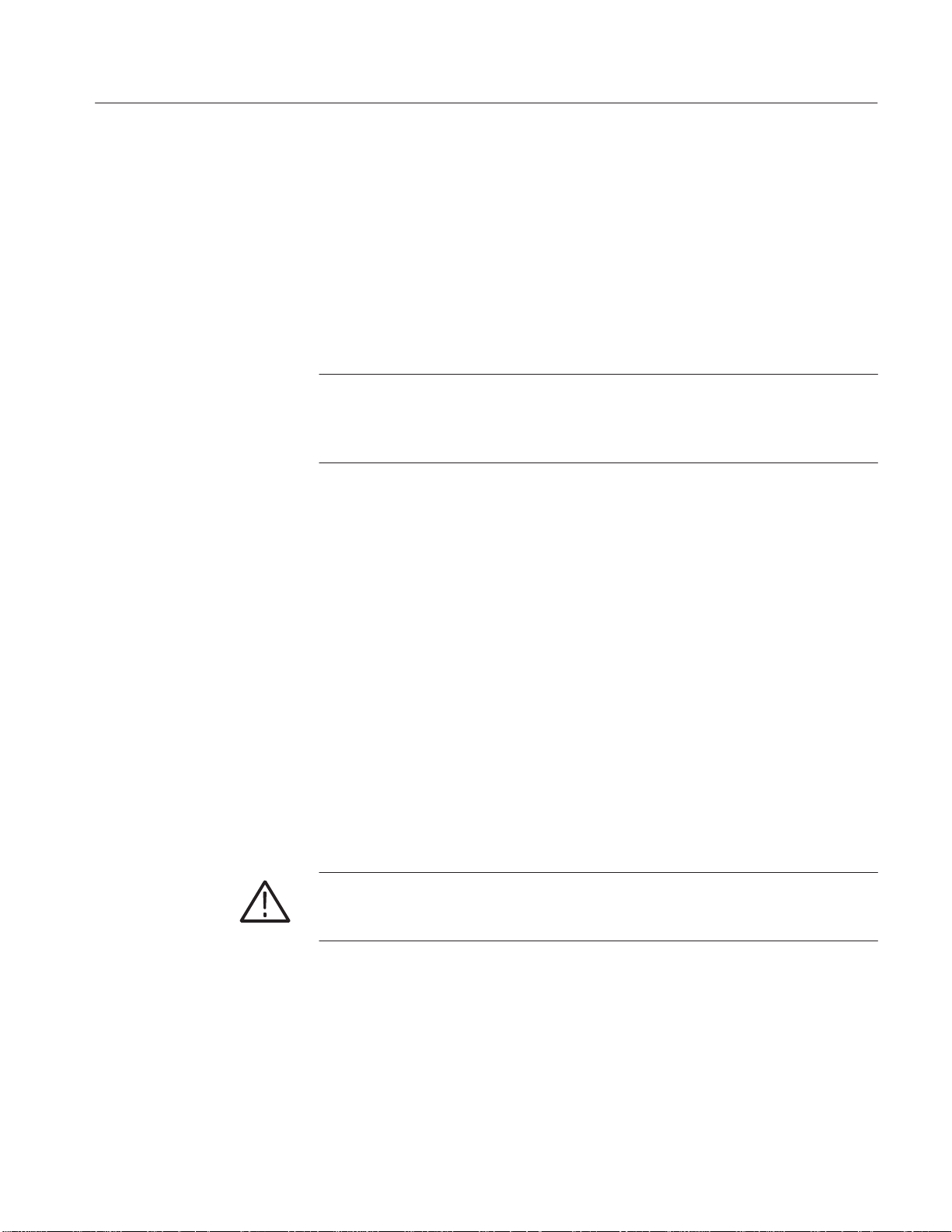
c. Remove the standard trim ring: Grasp the trim ring by its top edge; then
pry it up and lift it forward to snap it off of the front subpanel. Set the
trim ring aside face down on the work surface. See Figure 3.
AWG510 and AWG520 Rackmount Instructions
7
Page 16
Installation Instructions
Trim ring: when removing the trim ring,
grasp its back edge and vigorously flex it
upward before pulling it forward.
Menu Buttons
Figure 3: Trim Ring Removal
d. Install the trim ring from the rack adapter kit:
H Lay the trim ring supplied with the kit face down on the work
surface next to the standard trim ring.
H Without touching the carbon contact points on the menu buttons, lift
the menu buttons from the standard trim ring and install them in the
kit trim ring.
H Align the kit trim ring to the front subpanel and install. Firmly seat
the trim ring on the front subpanel.
H Find the front trim label that matches the one on the trim ring you
removed (the one that matches the model number of your AWG500).
Remove its adhesive backing and align to the trim ring you have just
installed to match its location on the one you removed. Press it
firmly to install.
8
AWG510 and AWG520 Rackmount Instructions
Page 17

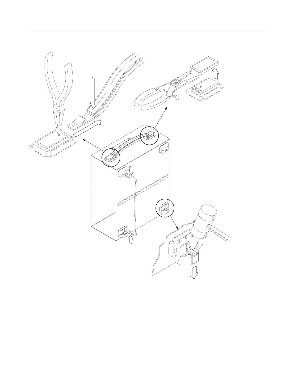
Handle Removal
Installation Instructions
Push down to flex
handle and flatten
against cabinet; then
pull it out.
Handle Cap
Removal
Flip Stand
Removal
Figure 4: Cabinet Hardware Removal
3. Remove cabinet hardware (cabinet removal is not required):
a. Orient the AWG500: Set the AWG500 so its left side (when facing the
front of the AWG500) is down on the work surface as shown in Figure 4.
Reference Figure 4 as you do substeps b through e.
AWG510 and AWG520 Rackmount Instructions
Foot Removal
9
Page 18

Installation Instructions
b. Remove the handle:
H Insert the tips of a pair of needle-nose pliers (Item 5) into the hole of
either handle cap. Push and hold to depress the handle release.
H While holding the handle released, pull it out of the slot in the
handle cap. Repeat procedure to remove the handle from the other
handle cap.
c. Remove the handle caps:
H Insert the retaining ring pliers (Item 6) into the opening created in
the handle cap when you removed the handle.
H While using the pliers to expand the handle cap outward, grasp it
and snap it off.
H Repeat procedure to remove the remaining cap.
d. Remove the flip stand: Grasp the flip stand by both sides near where it
joins each flip stand foot. Now compress the flip stand until the flip
stand ends clear the flip stand feet to complete the removal.
e. Remove the cabinet feet: Using a plastic-headed mallet (Item 7), strike
each foot on its inside edge until it releases from the cabinet. Remove all
four feet.
10
AWG510 and AWG520 Rackmount Instructions
Page 19

Installation Instructions
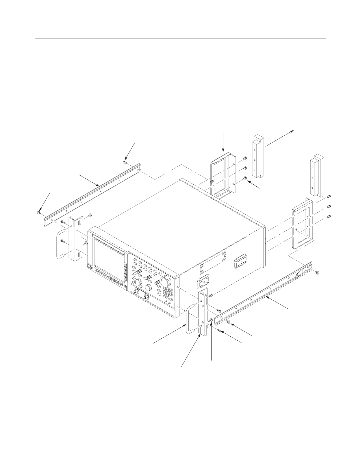
Install Kit Hardware
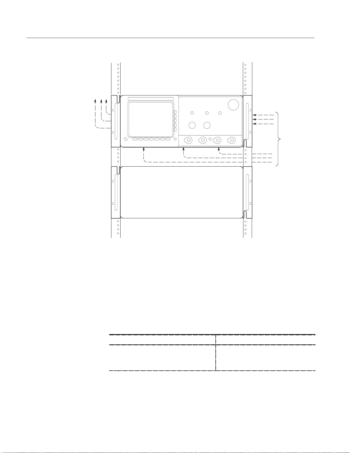
Left Inside Track (1)
10Ć32 screws (4)
Equipment Required: One screwdriver handle (Item1), one number two Phillips
tip (Item 2), and one number two pozidrive tip (Item 3),one T–20 Torx tip (Item
4).
Procedure:
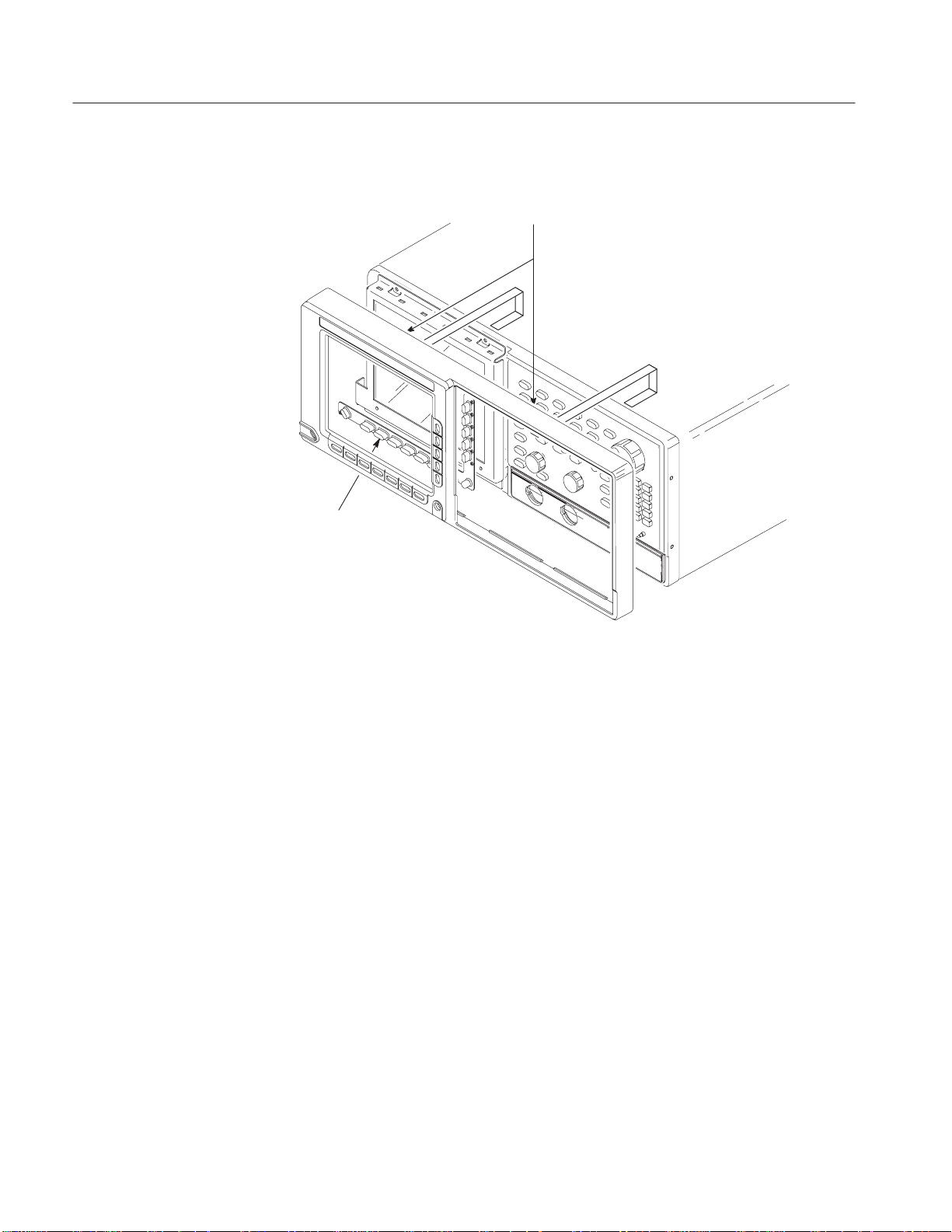
1. Assemble the hardware: Unpackage and identify the hardware shown in
Figure 5. Refer to Figure 5 as you perform the following steps. (The
parenthesized numbers appearing with the hardware items in the figure refer
to the quantity of the item used to install the kit hardware.)
Rear Brackets (2)
10Ć32 screws
Remove Rear Feet
M5ĂxĂ12 Screws (6)
Bracket Handles (2)
Figure 5: Installation of Kit Hardware to AWG500
AWG510 and AWG520 Rackmount Instructions
Right Inside Track (1)
10-32 Screws (4)
M4x12 Screws (4)
10-32 Screws (4)
Front Brackets (2)
11
Page 20

Installation Instructions
2. Install the rear brackets:
a. Orient the AWG500:
H Set the AWG500 so its bottom is down on the work surface and its
rear is facing you.
b. Remove rear-cover screws: Using a screwdriver with a T–20 Torx tip
(Items 1 and 4), remove the six screws (8–32) securing the two rear feet
to the AWG500. Remove the two rear feet installed.
c. Attach the brackets:six screws (M5x12) Using a number two Phillips tip
(Items 1 and 2) and six screws (M5x12), install the two rear brackets as
shown in Figure 5. When reinstalling the six screws at the rear panel,
tighten them to 16 inch-lbs torque.
3. Install front brackets:
a. Orient the AWG500:
H Set the AWG500 so its bottom is down and its right side is facing
you.
CAUTION. When attaching the brackets to the trim ring in step b that follows, be
sure to use the correct size screws as called out (M4x12). Installing longer
screws may damage the internal floppy disk drive of those products so equipped.
b. Attach the brackets:
H Locate the two front brackets and the four Phillips mounting screws
(M4x12) in Figure 5. Also locate the two front bracket handles and
the four number two pozidrive screws (10-32) used to mount them to
the front brackets.
H Align the two access holes on the bracket to the two mounting holes
in the right side of the trim ring.
H Using a screwdriver with a number two Phillips tip (Items 1 and 2),
install two screws (M4x12) to secure the bracket to the AWG500.
When installing the screws, tighten them to 16 inch-lbs of torque.
H Align the front-bracket handle to the front bracket. Using a
screwdriver with a number two pozidrive tip (Items 1 and 3), install
the two screws (10-32) to secure the handle to the bracket. When
installing the screws, tighten them to 28 inch-lbs torque.
H Rotate the AWG500 so that you face the left side and repeat the three
subparts just performed to install the left bracket.
12
AWG510 and AWG520 Rackmount Instructions
Page 21

4. Install the inside tracks:
a. Identify the left and right inside tracks:
H Locate the two inside tracks in Figure 5.
H Using Figure 6, identify the right from the left inside track.
b. Attach the tracks:
H Align the two mounting holes on the track to the two mounting
holes, one each in the right rear and the right front bracket.
H Using a screwdriver with a Pozidrive tip (Items 1 and 3), install the
right inside track to the front and rear brackets using two screws
(10-32). (Tighten the screw using 28 inch-lbs. of torque.) Note the
button latch should be facing away from the AWG500 and towards
its rear. Use Figure 6 as a guide.
H Rotate the AWG500 to face the left side and repeat subparts to install
the left inside rail.
Installation Instructions
Left track
(turn over and mount on left side
of AWG500).
Figure 6: Left and Right Inside Track Identification
This completes the installation of the rack-adapter hardware to the AWG500. To
complete the installation, Install Rack-Adapted AWG500.
AWG510 and AWG520 Rackmount Instructions
Note button latch is located
near the top edge of track.
Note button latch is located
near the bottom edge of
track.
Right track
(mount on the right side of
AWG500).
13
Page 22

Installation Instructions
Rackmount the RackĆAdapted AWG500
This procedure assembles and installs the slide-out tracks in the equipment rack,
and then installs the rack-adapted AWG500 in the rack.
The slide-out tracks permit the rack-adapted AWG500 to be extended out of the
rack for rear-panel and connector maintenance without removing the AWG500
from the rack.
NOTE. The rack hardware kit contains hardware needed for mounting the
AWG500 in several configurations. All of the hardware in the kit will not be
needed.
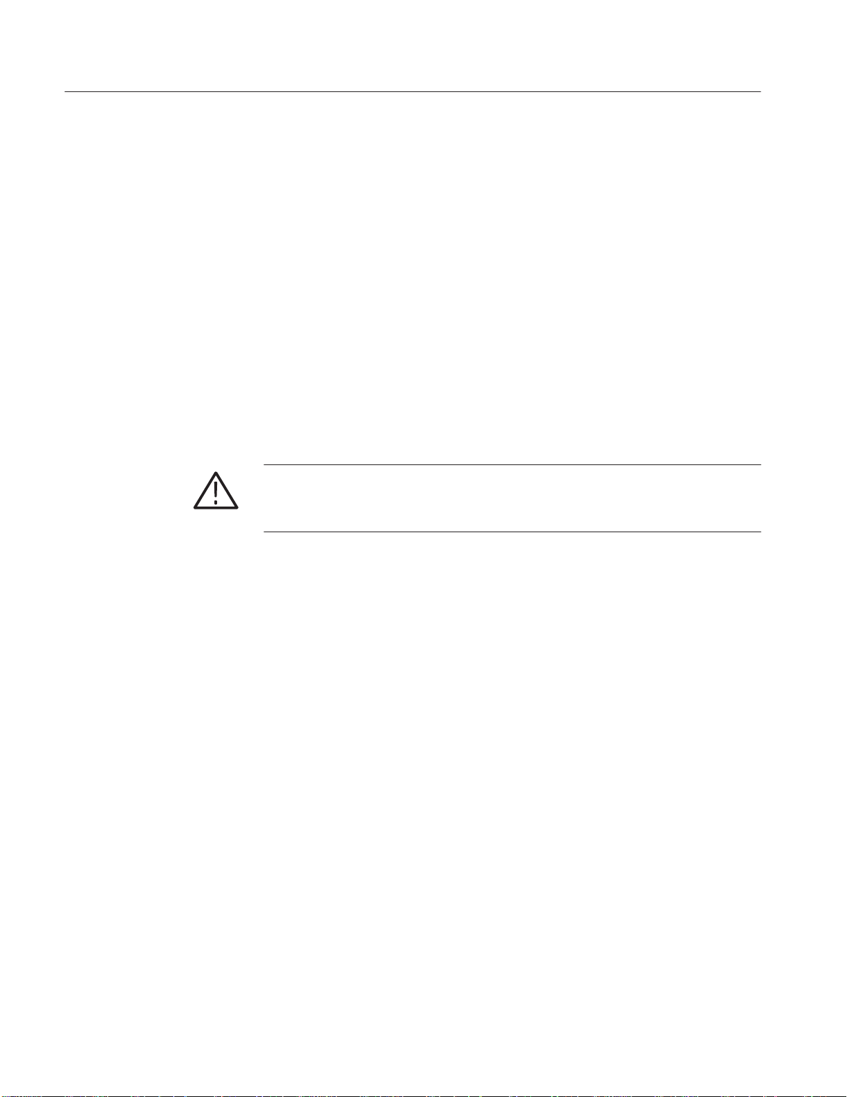
WARNING. If slide-out track assemblies are disassembled for maintenance, do
not interchange the left and right inner tracks when reinstalling them in the left
and right outer tracks. If you do so, you will defeat the extension stop (safety
latch) feature of the tracks. Equipment could, when extended, come out of the
slides and fall from the rack, possibly causing personal injury and equipment
damage.
Install Track Assembly
and AWG500 into the
Rack
Equipment Required: One screwdriver handle (Item1), one number two
pozidrive tip (Item 3).
NOTE. The slide-out track assemblies that are included in the rack-adapter kit
come partially assembled with the inner tracks inside of the outer tracks. Leave
them partially assembled to simplify their installation and to avoid accidental
swapping of their inner tracks. (See WARNING above.) If assemblies are
disassembled, use Figure 10-7 to match left and right slides. (Note that when the
left and right tracks are oriented as shown, the round cutout is below the square
cutout at the end of the both inner tracks.)
Procedure:
1. Assemble the slide-out track:
a. Identify the right vs. left slide-out track assemblies: find the date code
label on each assembly. The assembly to be mounted in the left side of
the equipment rack (the side nearest the left side of the AWG500 when it
is rackmounted) has a date code that ends with “LH,” for left hand. The
right assembly has a date code ending with “RH.”
14
AWG510 and AWG520 Rackmount Instructions
Page 23
Rear Flange
(Mounts to Rear
Rail of Rack)
Installation Instructions
b. Measure the distance between the front and rear rail of the equipment
rack.
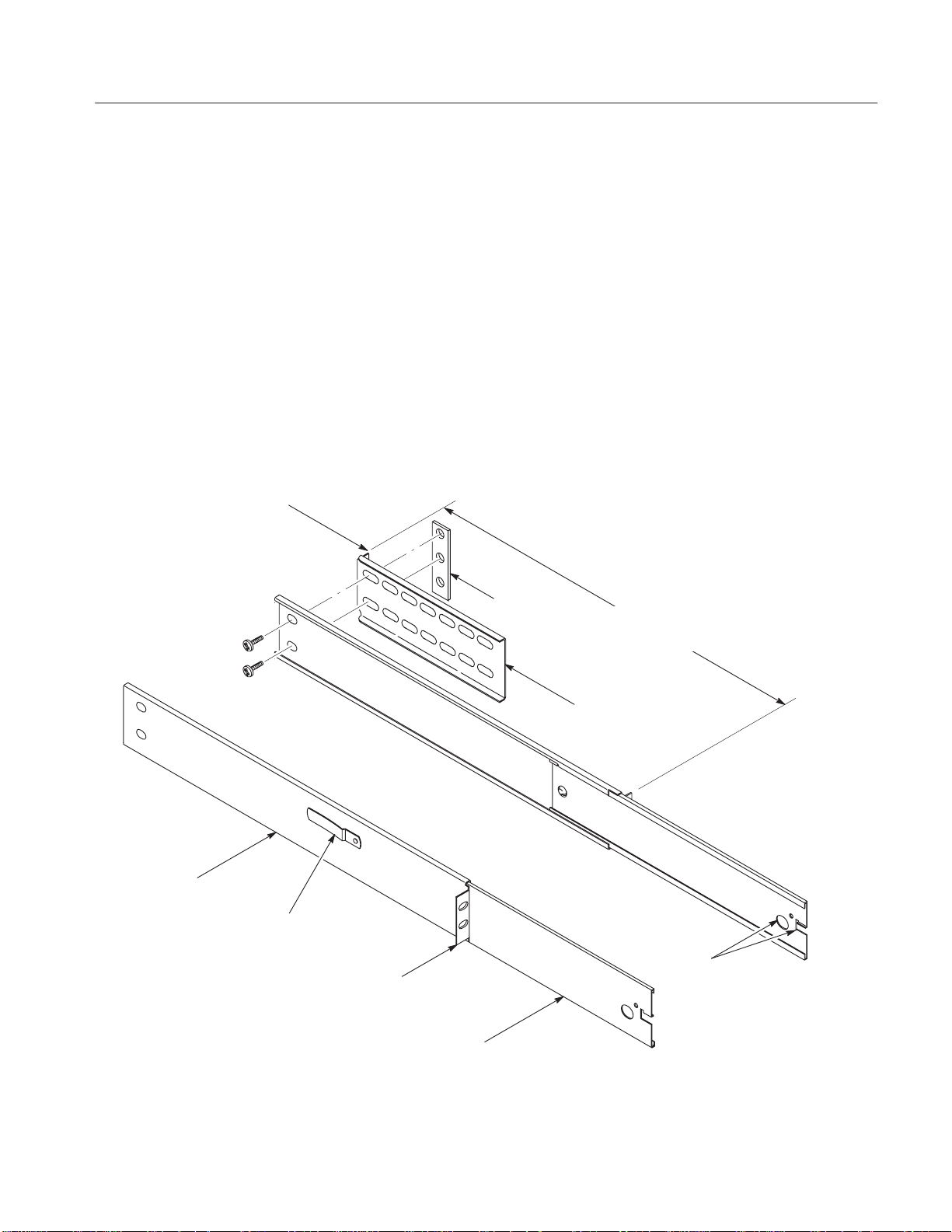
c. Align the rear bracket to the right slide-out track as shown in Figure 7.
Note the rear bracket has multiple pairs of mount-through holes. When
aligning the bracket and track, be sure to select a pair of holes that mount
the rear bracket so the flange-to-flange distance (see figure) matches the
front rail to rear rail spacing just measured.
d. Using a screwdriver with a number two pozidrive tip, secure the rear
bracket to the right slide out track using two screws (10-32) and a bar
nut as illustrated. Leave the screws loose so that the overall length of the
slide out track assembly can be adjusted when installing it in the rack.
e. Repeat substeps c and d to assemble the left slide-out track assembly.
Right SlideĆOut Track Assembly
Outer Track
Note button latch
is closest to top of
Left SlideĆOut Track Assembly
track.
Front Flange
(Mounts to Front
Rail of Rack)
Inner Track
Bar Nut
FlangeĆto Flange: 20.25 in.
(514.4 mm) min to 26.50 in.
(673.1 mm) max
Rear Bracket
Round and
Square Cut
Outs
Figure 7: Assembly of SlideĆOut Track Assemblies
AWG510 and AWG520 Rackmount Instructions
15
Page 24
Installation Instructions
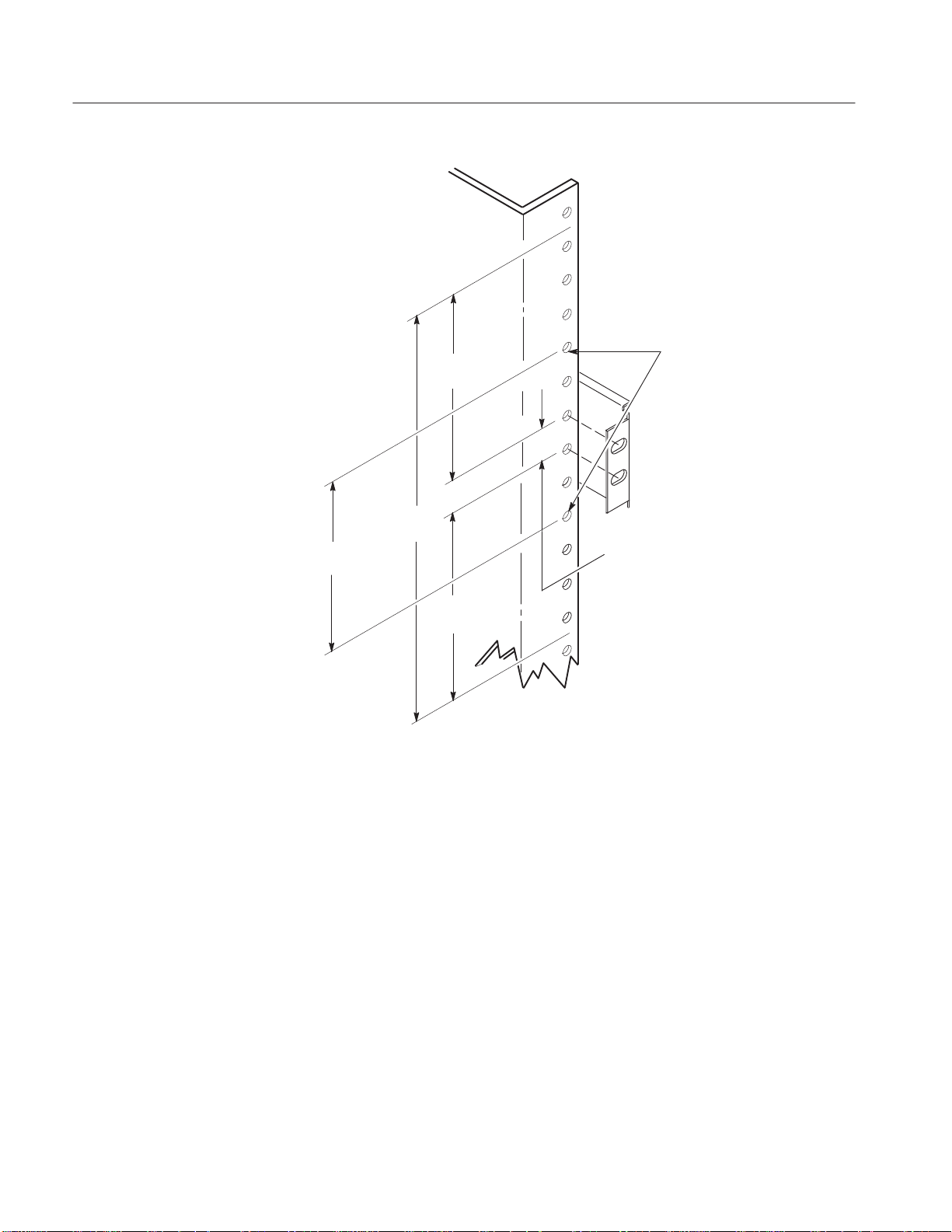
2. Mount the slide-out track assemblies:
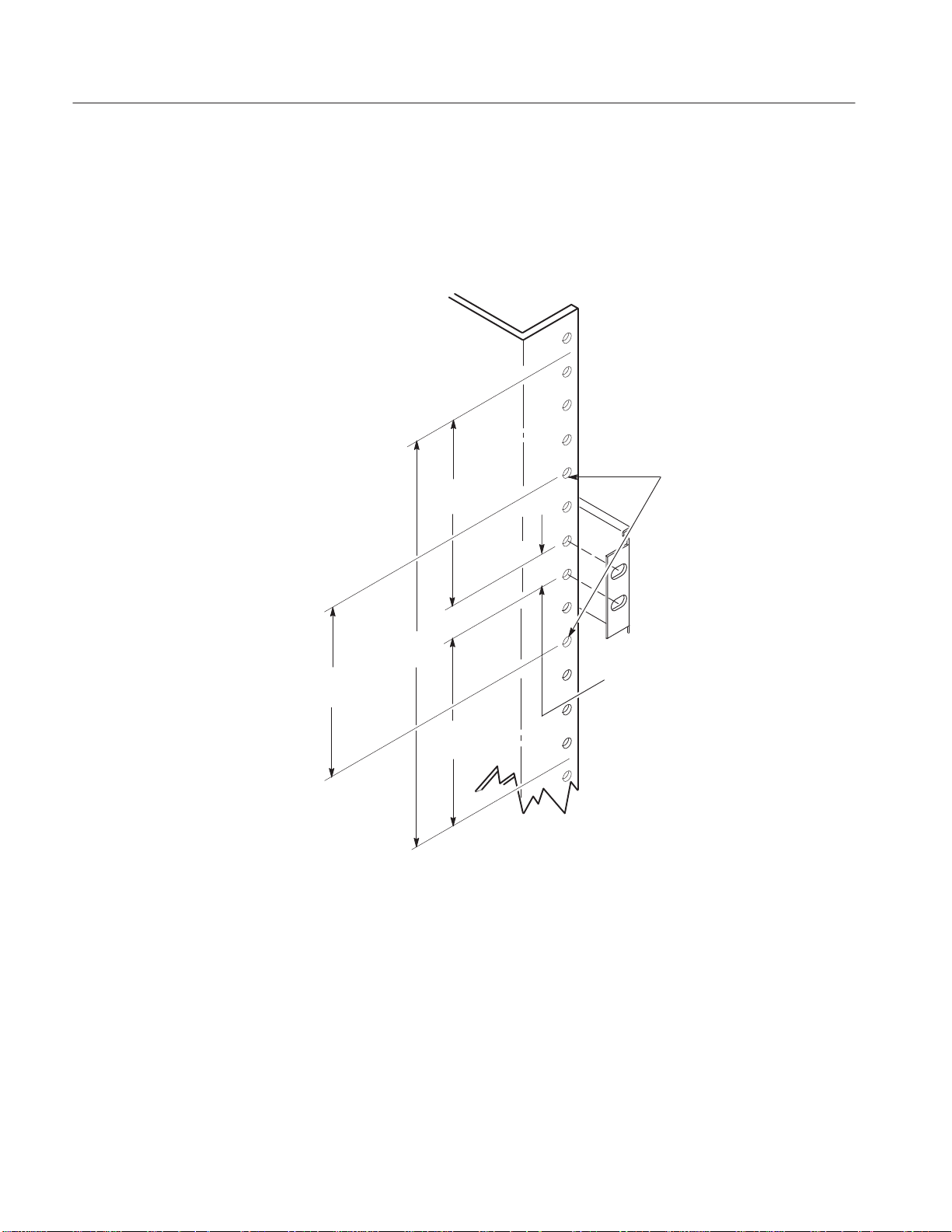
a. Select the mounting position in rack: Select two ½ inch spaced holes in
the front rail. Verify that the 3¼ inch and 7 inch clearances exist relative
to those mounting holes. See Figure 8.
SECURING HOLES
(tapped for 10-32 screws)
3 IN.
(76.2 mm)
(82.55 mm)
7 IN.
(177.8 mm)
(82.55 mm)
3.25 IN
3.25 IN.
.50 IN (12.7 mm).
(For Correct
Position of Securing
Holes)
Figure 8: Vertical Clearances for Rack Installation (LeftĆFront Rail Shown)
16
AWG510 and AWG520 Rackmount Instructions
Page 25
Installation Instructions
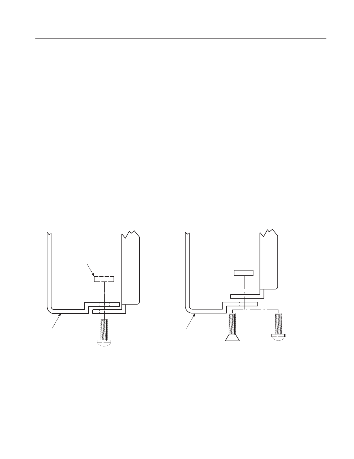
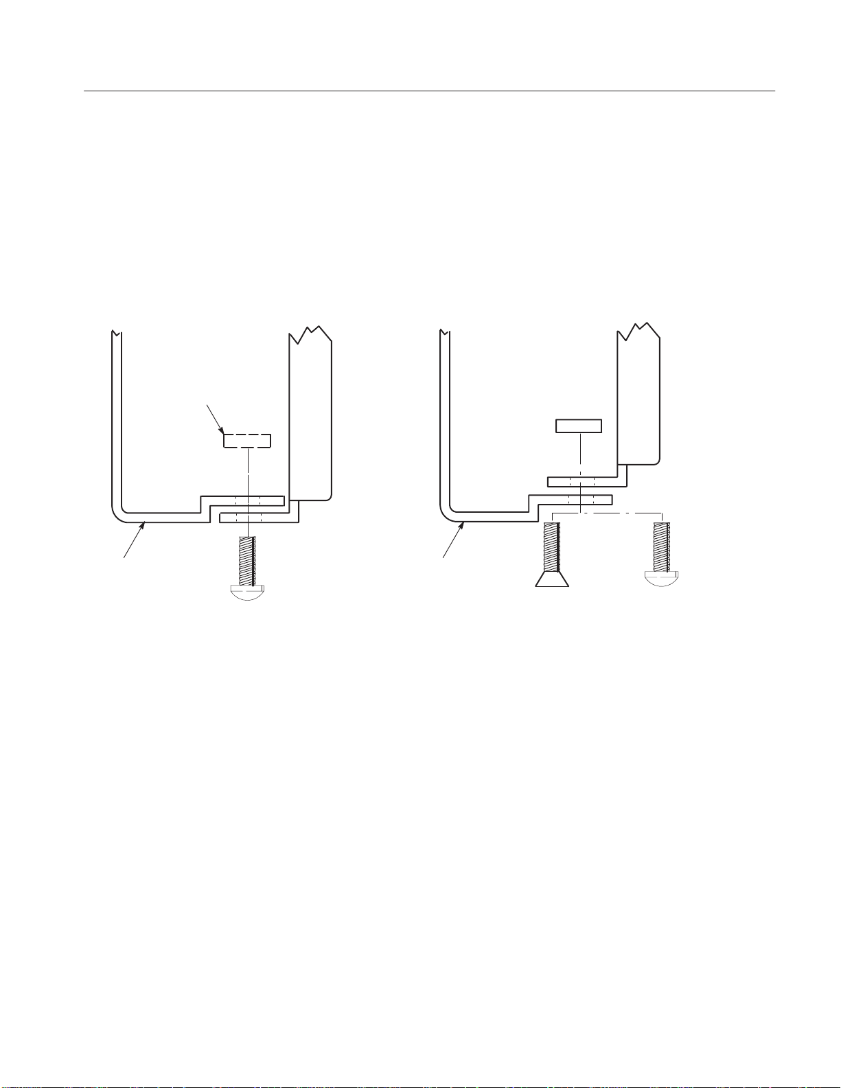
b. Select mounting method according to rack type:
H To mount the slide-out tracks with their front and rear flanges
outside of the front and rear rails, use the method A shown in
Figure 9 when doing substep c. Add a bar nut to the installation only
if the rails have untapped holes.
H To mount with front and rear flanges inside of rails, use the
mounting method B outlined in Figure 9. This mounting method
assumes untapped holes.
c. Install in rack: Using the method and hardware determined from substep
b, secure the right slide-out track assembly to its front and rear rails. The
screws should be fully, but lightly, seated so mounting can be adjusted
later.
d. Fix the length of the slide-out track assembly: Tighten the screws left
loose in step 1, substep d to fix the front to rear flange spacing of the
slide-out track assembly.
LeftĆFront Rail
e. Mount the left slide-out track assembly: Repeat substeps a through d to
mount the left slide-out track assembly.
Left SlideĆOut Track Left SlideĆOut Track
Use a bar nut if front rails
are not tapped
LeftĆFront Rail
10Ć32 Pan Head
Screws (4)
Use two flat head screws if the cabinet rail have
countersunk mounting holes; otherwise use two
pan head screws
Mounting Method A Mounting Method B
10Ć32 Flat Head
Screws (4)
10Ć32 Pan Head
Screws (4)
Figure 9: Installation of SlideĆout Track Assemblies in Rack (Top View)
AWG510 and AWG520 Rackmount Instructions
17
Page 26

Installation Instructions
3. Mount AWG500 in rack:
a. Install the AWG500:
H Working from the front of the rack, slide the inner track of each
slide-out track assembly until it extends out the front of the rack.
Continue to slide them out until they lock.
H Insert the left and right tracks that extend from the rear of the
AWG500 into the ends of the tracks just extended. Make sure the
tracks mounted on the AWG500 slip inside the inner tracks extended
earlier.
H Slide the rear of the AWG500 backwards until it stops.
H Push to release the button latches, located on the outside of the each
track, and continue to slide the AWG500 all the way into the cabinet.
b. Level the rackmounted AWG500:
H Tighten the four screws that were left loose at the rear of the rack
when you did step 2, substep c. then pull the AWG500 part way out
of the rack. (Tighten 10-32 screws using 28 inch-lbs of torque.)
H Be sure the four screws that were left loose at the front of the rack
are loose enough to allow the slide-out track assemblies to seek their
normal positions.
H Retighten the four screws and push the AWG500 all the way into the
rack. If the tracks do not slide smoothly, readjust the level using the
method just detailed.
H When leveling is completed, tighten the 10-32 screws using
28 inch-lbs of torque.
c. Secure the AWG500 and install the line cord:
H Locate the four 10-32 screws. Insert each screw through its recessed
washer, its metal flat washer, and its plastic flat washer as shown on
the data sheet included with the hardware kit.
H Using a number two pozidrive screwdriver, install the screw/washer
assembly in one of the two mounting holes in the right front bracket.
Repeat for the second mounting hole. Tighten both screws using
28 inch-lbs of torque.
H Install the two remaining screw/washer assemblies in the left front
bracket using the method just described.
18
H Reinstall the power cord.
AWG510 and AWG520 Rackmount Instructions
Page 27

Replaceable Mechanical Parts
This section contains a list of the replaceable components and accessories that
are used to adapt the TLS or TDS Oscilloscope for mounting in a standard
19-inch (48.3 mm) rack. Use this list, as described below, to identify and order
replacement rackmounting hardware. See the service manual for your TLS or
TDS Oscilloscope for lists of all replaceable mechanical parts not related to
rackmounting.
Parts Ordering Information
Replacement parts are available from or through your local Tektronix, Inc.
service center or representative.
Changes to Tektronix products are sometimes made to accommodate improved
components as they become available and to give you the benefit of the latest
circuit improvements. Therefore, when ordering parts, it is important to include
the following information in your order:
H Part number
H Instrument type or model number
H Instrument serial number
H Instrument modification number, if applicable
If a part you order has been replaced with a different or improved part, your local
Tektronix service center or representative will contact you concerning any
change in the part number.
Using the Replaceable Parts List
The tabular information in the Replaceable Parts List is arranged for quick
retrieval. Understanding the structure and features of the list will help you find
the all the information you need for ordering replacement parts.
Item Names
In the Replaceable Parts List, an Item Name is separated from the description by
a colon (:). Because of space limitations, an Item Name may sometimes appear
as incomplete. For further Item Name identification, U.S. Federal Cataloging
Handbook H6-1 can be used where possible.
AWG510 and AWG520 Rackmount Instructions
19
Page 28

Replaceable Mechanical Parts
Indentation System
Abbreviations
This parts list is indented to show the relationship between items. The following
example is of the indentation system used in the Description column:
1 2 3 4 5 Name & Description
Assembly and/or Component
Attaching parts for Assembly and/or Component
(END ATTACHING PARTS)
Detail Part of Assembly and/or Component
Attaching parts for Detail Part
(END ATTACHING PARTS)
Parts of Detail Part
Attaching parts for Parts of Detail Part
(END ATTACHING PARTS)
Attaching parts always appear at the same indentation as the item it mounts,
while the detail parts are indented to the right. Indented items are part of, and
included with, the next higher indentation. Attaching parts must be purchased
separately, unless otherwise specified.
Abbreviations conform to American National Standards Institute (ANSI)
standard Y1.1
20
AWG510 and AWG520 Rackmount Instructions
Page 29

Replaceable Mechanical Parts
Cross index - mfr. code number to manufacturer
Mfr. code Manufacturer Address City, state, zip code
TK0435 LEWIS SCREW CO 4300 S RACINE AVE CHICAGO IL 60609-3320
TK1163 POLYCAST INC 9898 SW TIGARD ST TIGARD OR 97223
TK1321 BERGFORD & ASSOCIATES 2705 WESTWIND DR NW OLYMPIA WA 98502
TK1465 BEAVERTON PARTS MFG CO 1800 NW 216TH AVE HILLSBORO OR 97124-6629
TK1719 NEDELCO BV (THOMAS & BETTS) POSTBUS 6431 3002 AK ROTTERDAM THE NETHERLANDS
0J9P9 GEROME MFG CO INC PO BOX 737
0KB01 STAUFFER SUPPLY 810 SE SHERMAN PORTLAND OR 97214
06383 PANDUIT CORP 17301 RIDGELAND TINLEY PARK IL 07094-2917
06666 GENERAL DEVICES CO INC 1410 S POST RD
28520 HEYCO MOLDED PRODUCTS 750 BOULEVARD
74868 AMPHENOL CORP
R F CONNECTORS (OPNS)
76814 NORTHERN ENGRAVING CORP 803 S BLACK RIVER ST SPARTA WI 54656-2221
80009 TEKTRONIX INC 14150 SW KARL BRAUN DR
403 NORTH MAIN
PO BOX 39100
P O BOX 160
1 KENNEDY AVE DANBURY CT 06810-5803
PO BOX 500
NEWBERG OR 97132
INDIANAPOLIS IN 46239-9632
KENILWORTH NJ 07033-1721
BEAVERTON OR 97077-0001
AWG510 and AWG520 Rackmount Instructions
21
Page 30

Replaceable Mechanical Parts
Fig. &
index no.
13- 016-1675-50 1 MOUNTING KIT:RACK MOUNT KIT 80009 016167550
-1 101-0142-01 1 .TRIM,DECORATIVE:FRONT 80009 101014201
-2 334-9589-00 1 .MARKER,IDENT:MKD AWG510,POLYCARBONATE 80009 334958900
-3 334-9590-00 1 .MARKER,IDENT:MKD AWG520,POLYCARBONATE 80009 334959000
-4 367-0022-00 2 .HANDLE,BOW:4.579 L,BRS CRPL 80009 367002200
-5 407-4020-00 2 .BRACKET,SUPPORT:FRONT,ALUMINUM 80009 407402000
-6 212-0215-00 4 .SCREW,MACHINE:M4x12MMĂL,PNH,STL,MFZN-C,CROSS
-7 212-0507-00 4 .SCR,MACHINE:10-32 X 0.375,PNH,STL,CD PL,POZ 80009 ORDER BY DESC
-8 351-0313-00 1 .GUIDE,RACKMOUNT:19.218 L,PAIR 80009 351031300
-9 212-0507-00 4 .SCR,MACHINE:10-32 X 0.375,PNH,STL,CD PL,POZ 80009 ORDER BY DESC
-10 351-0623-00 1 .SLIDE,DWR,EXT:22.0x1.54,STEELSAFETY CONTROLLED 80009 351062300
-11 407-4555-01 2 .BRACKET,SUPPORT:SIDE,ALUMINUM 80009 407455501
-12 212-0214-00 6 .SCREW,MACHINE:M5x12MMĂL,PNH,STL,ZN-PL,CROSS
-13 212-0509-00 4 .SCREW,MACHINE:10-32 X 0.625,PNH,STL CD PL,POZ 80009 ORDER BY DESC
-14 210-1003-00 4 .WASHER,FLAT:0.2 ID X 0.438 OD X 0.036 BRSNP 80009 ORDER BY DESC
-15 210-0142-00 4 .WASHER,PLAIN:5.5MM ID X 12MM OD ,TEFLON 80009 ORDER BY DESC
Tektronix
part no.
Serial no.
effective dscont
Qty Name & description Mfr.
code
80009 ORDER BY DESC
REC
80009 ORDER BY DESC
REC,W/FLAT & LOCK WASHER
Mfr. part no.
22
AWG510 and AWG520 Rackmount Instructions
Page 31

Replaceable Mechanical Parts
10
11
9
12
8
12
9
6
7
11
7
****
****
1
****
Figure 10: Exploded View
****
13
14 15
9
7
10
8
5
7
6
6
9
AWG510 and AWG520 Rackmount Instructions
23
Page 32

Replaceable Mechanical Parts
24
AWG510 and AWG520 Rackmount Instructions
Page 33

Page 34

Page 35

ៜȡྡ
ᅞ৬ᡷ
ূሴϋδᡑΤοπίοϡϋ iii................................
Ϗθϡϋ 1..................................................
ѩуЯТрїпȦЭуш
డ௯ϲᔼιϫοϡώйњȼй 3................................
ѩуЯϘώᙕα 5..........................................
ᘬᡗϊษೱ
ೈϲཏϡϫሰϋ 6.............................................
ѩуЯТрїпȦЭушώᙕα 7..............................
ѩуЯϘώᙕα 13.............................................
ᅞĂ10-1: డ௯ώᣤ 2.......................................
ᅞĂ10-2: ѩуЯўЦѳшിĂAWG500 4.........................
ᅞĂ10-3: шѪѠѪѳаɊሰ៌ёэѫ᥈ɋώରη 8.............
ᅞĂ10-4: бȼйት፥ᙴᙊώରη 9...........................
ᅞĂ10-5: ўЦѳшᙴᙊώᙕα 11.............................
ᅞĂ10-6: ФѳеФщȦшѩуЯώຸώ೨ᛌ 13.................
ᅞĂ10-7: йѩФщТЦшȦшѩуЯώቈϟᢩφ 15...............
ᅞĂ10-8: йѩФщТЦшȦшѩуЯϲ
ȡȡȡȡᙕαϫໝώᅢᎾЯѪТѩѳй 16...............
ᅞĂ10-9: йѩФщТЦшȦшѩуЯϲ
ȡȡȡȡѩуЯȦѬȼѫϋᙕαϫ 17.......................
1.......................................
5....................................................
AWG510 and AWG520 Rackmount Instructions
i
Page 36

ៜྡ
ᘽ৬ᡷ
ᘽĂ2-1: ᒰಭ 2..........................................
ᘽĂ2-2: ѩуЯўЦѳшᙕαೈϋᘬᡗϊษೱ 5..............
AWG510 and AWG520 Rackmount Instructions
ii
Page 37
ূሴϋδᡑΤοπίοϡϋ
ূሴϋδᡑΤοπίοϡȢడ௯ϲδᡑϋϊϫሰϋȢྡώྲྀϲᘬκΪᓉϟίπ
εΤȣ
ဤȦᆵȦᙴᙊෲஹϏȢᇬ៧ώеȼѓй৷ώϟά๔ΨϞιȣဤȦᆵȦᙴᙊෲ
ஹάᘬᡗϊწϏȢеȼѓйᙕлѳпȼϞχΪ៤ΤϯλίπεΤȣ
ᅍዎᛝ෮ϋΪαϫ
፭ྲྀ
ѕѭȼцУѳаኬᏪϋτΤφ
ᆸឿώ௭නάϪϞιώχȢడ௯ώᇜፏϲରηοჵዖχώѕѭȼцУѳаኬᏪϏȢ
ᇤዐϋ๔ϯϊΤχίπεΤȣ
డ௯ϏȢᇜፏεϬοჵዖϋΪΤφূሴϋᡑεϬϫᇟൗϋϊσφΪϪȢᇜፏϲ๔
ϯϊΤψȢዎώೢኰᙴᚬϏᓾᣏᄮψᒱθᑅৌϞχქႺιϫಲϬάϪዧᛑ௭න
χιȣ
ѕѭȼцУѳаኬᏪϲ๔ΦწϏȢЪзѭйгȼїώሰፊϋТФнѬȼпϲᓾηȢ
ᇤηφίπεΤȣϊΪȢᑶ࿒χϏТїѪбȼзѧѳϋዐηοТФнѬȼп
ϲᡑηφΤϞιώχȢΪ៤ΤϯλίπεΤȣ
ᐬᇚϊᑅරгȼщώᡑ
ᖯૐᑹώಲϬάϪϞιώχȢམᏪεϬοᑅරгȼщରϏᡑηϊΤχίπεΤȣ
їѭȼіώᇜኳ
ஶᑅώ௭නάϪϞιώχȢᑅරάᓾσφΤϫჵዖώᤩϘώїѭȼіώᖴέູηϏ
๔ϯϊΤχίπεΤȣ
ᐬᇚϊᇜፏɊаѩѳщɋ
డ௯ϏȢТȼйȦѩФѳώϫ3ᇾྰᑅරгȼщϲᏌθφᇜፏεϬϞιȣஶᑅϲᗲ
αϫοϡȢᘬκТȼйጼདྷώϫнбушϋູηϳχίπεΤȣ3-2Трїпϲ
ᡑηφ2ᇾྰᑅරϋᇜኳιϫწϋϢȢᘬκТрїпώТȼйᇾϲᇜፏηφίπεΤȣ
Тȼйጼདྷ
AWG510 and AWG520 Rackmount Instructions
3Ć2ĂТрїп
iii
Page 38

ূሴϋδᡑΤοπίοϡϋ
ᑅతᐪϊૡᙩ
ஶᑅϞοϏᖯૐϊωώΪνϬάϪϞιώχȢгэЯпᑹϋభໜεϬφΤϫᓾᣏᏪ
ᑅϲᔧηφΫϩїѭȼіϲᇜኳιϫϨΦϋηφίπεΤȣ
COMгэЯпϏዧፏаѩѳщϋᇜኳεϬϞιώχȢᛑᒰιϫᑅϲૃΨϊΤχίπ
εΤȣ
ஶᑅϞοϏᖯૐώ௭නάϪϞιώχȢгэЯпϋϏམᏪεϬοᗏରώᑅϲૃ
ΨϊΤχίπεΤȣ
ЭѣѓэушȢЫѐȼώϪରη
డ௯ᓢᙴϋϏᑅώၪάϪϞιώχȢЫѐȼϤёэѫϏϪରεϊΤχίπ
εΤȣ
ᐬᇚϊђѥȼкώᡑ
ᖯૐϊωώ௭නάϪϞιώχȢམᏪεϬοᏪώђѥȼкରϏᡑηϊΤχί
πεΤȣ
ᗯኬᏪᤩϘώᇜᄨ
ஶᑅώ௭නάϪϞιώχȢᑅරάᓾσφΤϫᤩгэЯпϞοϏᙴᙊϋϏᄨϬϊ
ΤχίπεΤȣ
డ௯ᛝ෮ϋΪαϫ
፭ྲྀ
డ௯άᔨϬοჵዖχώᡑ
ஶᑅώ௭නάϪϞιώχȢడ௯άᔨϬοჵዖχϏᡑηϊΤχίπεΤȣ
Ьй፦χώᡑ
ᖯૐώ௭නάϪϞιώχȢᕺᖯᆭώЬйάϋϫϨΦϊწၪχϏᒰελϊ
ΤχίπεΤȣ
డ௯ώᔮ
డ௯άૡᔮηϊΤϨΦȢွᚬϋᔮηφίπεΤȣ
უψབྷϯϬϫწ
უψབྷϯϬϫწϏȢᘬκᑶ࿒ϞοϏᗎᕤᐹϞχδᤢᡭίπεΤȣ
iv
AWG510 and AWG520 Rackmount Instructions
Page 39

ূሴϋδᡑΤοπίοϡϋ
ᡑ෬ψўȼЯϋτΤφ
ўыѥТѫχϏȢূሴϋᡑηφΤοπίοϡϋȢྡώϨΦϊᡑ෬ϲᡑιϫწ
άϪϞιȣ
൙ĂᅍዎϤᆸឿϋ௭ଲϲΪϨϜιΪνϬώϫწϋȢνώ௭නϲᗲαϫοϡώ፭
ྲྀάభεϬφΤϞιȣ
፭ȧడ௯ϲኻၽιϫΪνϬώϫწώ፭ྲྀάభεϬφΤϞιȣ
డ௯ϋϏȢྡϋྨιᡑ෬άభεϬφΤϫწάϪϞιȣ
DANGERȧ
οπρϋᅍዎϤᆸឿϋ௭ଲϲΪϨϜι௭නάϫγψϲྨηφΤϞιȣ
WARNINGȧ
ᇜᐪϋȢᅍዎϤᆸឿϋ௭ଲϲΪϨϜι௭නάϫγψϲྨηφΤϞιȣ
CAUTIONȧ
డ௯ΪϨϓᛕడ௯ϋኻၽϲΪϨϜι௭නάϫγψϲྨηφΤϞιȣ
డ௯ქϋϏȢྡώϨΦϊзѳќѫάభεϬφΤϞιȣ
ᑅᙴᚬχ
ϫγψϲྨηφ
ΤϞιȣ
ᛝ෮ᡑᇜፏጼདྷ
χϫγψϲྨ
ηϞιȣ
భώᙕεϬο
ᇢៀϲўыѥТ
ѫχ༲ηφί
πεΤȣ
ᓳ၅ᇤχϫ
γψϲྨηφΤ
Ϟιȣ
AWG510 and AWG520 Rackmount Instructions
v
Page 40

ূሴϋδᡑΤοπίοϡϋ
vi
AWG510 and AWG520 Rackmount Instructions
Page 41

Ϗθϡϋ
γγχϏȢAWG510ĂിȿAWG520ിᔤᕈുмэѬȼпϋѩуЯТрїпȦЭуш
ϲᙕαϫώϋᘬᡗϊйњȼйȢϪᙕαοწώడ௯ώᒰϘώುϋτΤφᇢ
ៀηϞιȣడ௯ϲѩуЯϋϪᙕαϫሰϋϨίΪᓉϟίπεΤȣ
γώᇢៀၱχϏȢAWG510ĂിȿAWG520ിᔤᕈുмэѬȼпϲቭηφAWG500
зѪȼкψభၒηϞιȣ
ѩуЯТрїпȦЭуш
γώѩуЯТрїпȦЭушϲት፥ιϫψȢAWG500зѪȼкϲᘸၠിĂ483mm{19
Фѳс}ώѩуЯϋϪᙕαϫγψάχέϞιȣ
፭ĂĂѩуЯТрїпȦЭушϋϏȢѦыѐȼеѫȦпФїώฦώΤοѬȼѫάᙕኰ
ηφΤϞιȣѦыѐȼеѫȦпФїରώѩуЯϲᡑιϫწϏȢѩуЯϋѦы
ѐȼеѫȦпФїώฦϲଫαϫᘬᡗάϪϞιȣ
ѩуЯТрїпȦЭушϏྡώᜡχ๘ᓾχέϞιȣȧ
ᒰώᛝლ
H ᘸၠпФїώAWG500зѪȼк๘ᓾȢѩуЯўЦѳшᡑώѩуЯТрїпȦ
ЭушɊ016-1675-50ɋϲ๘ᓾιϫȣ
H AWG5x0Ăop1RിɊѩуЯТрїпᙕɋϲ๘ᓾιϫȣɊడ௯ዎኦώѩуЯТрї
пȦЭушάФѳйшȼѫεϬοჵዖχၐεϬϞιȣɋ
γώᇢៀၱχϏȢAWG500зѪȼкడ௯ዎϘώЭушώФѳйшȼѫȢѩуЯϘ
ώЭушώФѳйшȼѫȢΪϨϓడ௯ώѩуЯϘώᔼᜡϋτΤφᇢៀηφϪ
Ϟιȣ
4њȼиώᅞ10Ć2ϋѩуЯТрїпȦЭушϲФѳйшȼѫηοడ௯ώᆣᜡᅞϲྨ
ηϞιȣ
γώᇢៀၱϋှΤᐬᇚϊᜡχడ௯ϲѩуЯϋᔼηφΪΤϋϊϫწϏȢྡώ
ɖᒰಭɗώϋభၒηοៜϲၼΤφȢడ௯ώᒰϏᛝლεϬϞιȣνϬରώ
ᜡχడ௯ϲФѳйшȼѫηοწϏȢᛝლεϬοཅᡍϲοεϊΤγψάϪϞιȣ
ᣤШТϏĂᅞ10Ć1ĂώϨΦϋȢడ௯ώኦ៌ψᏬώᙴᚬΫϩϪϞϬȢడ௯ຸኦώ
ѕСѳΫϩᕓၐεϬϞιȣѩуЯȦЭѣѓэушᓢώહᑙάམᏪεϬοᗏᓢχΪ
ΤίπεΤȣ
AWG510 and AWG520 Rackmount Instructions
1
Page 42

Ϗθϡϋ
ᣤШТ
ᅡέၐη
ᣤШТ
ϟ
ᒰಭ
ᅞĂ10Ć1: డ௯ώᣤ
νώኾώཅᡍϋτΤφϏȢѦȼжȦўыѥТѫϞοϏеȼѓйȦўыѥТѫϲ༲
ηφίπεΤȣ
ྡώᘽϋྨηοៜϋηφϏȢѦȼжȦўыѥТѫϞοϏеȼѓйȦўыѥТѫώ
భໜᓢᡆάᛑูϋϊϪϞιȣ
ᘽĂ2Ć1: ᒰಭ
ȡៜ
હᑙȢᒰཾ
ѩуЯȦЭѣѓэушᔼཾ +10_ C Ɂ +40_ C
ᇢȡៀ
AWG510 and AWG520 Rackmount Instructions
2
Page 43

డ௯ϲᔼιϫοϡώйњȼй
ѩуЯТрїпᙕέώAWG500зѪȼкϲᔼιϫѩуЯϋϏȢྡώйњȼйϲᘬ
ᡗψηϞιȣ
H ᅢᎾȧ178 mmĂ(7Фѳс) ქ
H ѩуЯώຸώѬȼѫώᙽȧ448 mm (17 5/8ĂФѳс)
H ๔έȧ600 mm (23Ă5/8ĂФѳс)ȡქ
൙ĂᣤᡑతώϬώοϡȢᑅරбȼіѫᑹώᙴёэѫϘώбȼіѫᇜኳȢΪ
ϨϓѩуЯϘώడ௯ώት፥ώοϡϋȢქభώйњȼйϏᏣෂᛝηφίπεΤȣ
йњȼйάᛝχέϊΤწϏȢడ௯άЪȼѐȼђȼшჵዖϋϊϪȢᒰάᙔূᏪ
ϋϊσοϪȢᏤཟηφηϞΦγψάϪϞιȣ
Ϗθϡϋ
AWG510 and AWG520 Rackmount Instructions
3
Page 44

Ϗθϡϋ
587.1
426.72
549.0
450.60
484.6
30.86
76.20
468
ᅞĂ10Ć2: ѩуЯўЦѳшിĂAWG500
46.5138.1
549.0
30.86
177.2
88.6
AWG510 and AWG520 Rackmount Instructions
4
Page 45

ѩуЯϘώᙕα
γώχϏĂAWGĂ500ĂзѪȼкϲѩуЯϘᔼιϫᜡϲၧϲᏉσφᇢៀηϞιȣ
6ĂњȼиώɖೈϲཏϡϫϋሰϋɗΫϩΪᓉϟίπεΤȣ.
፭
ၒηϞιȣop-1RിϏᘸၠിϋѩуЯўЦѳшȦЭушώ৬ᙴάడ௯ዎϋϪᙕ
αϩϬοჵዖχၐεϬφΤϞιώχȢAWG500డ௯ዎϋιϫೈϏᘬᡗϏ
ϪϞλϳȣ
ᘬᡗϊษೱ
ᘽĂ2Ć2Ăϋೈϋᘬᡗϊษೱώ৬ᡷϲྨηϞιȣ
OpĂ1RĂിώడ௯ϲѩуЯϋᔼιϫწψȢᘸၠിϋѕУȼѫщȦЭушϲᡑΤφ
ѩуЯϋᔼιϫწψχȢᘬᡗψιϫษೱάϊϪϞιȣ 6њȼиώɖೈώሰ
ϋɗϲΪᓉϟϋϊσφȢೈᓢᡆϋθοษೱϲᡑηφίπεΤȣ
ĂĂγώᇢៀၱχϏȢᘸၠിψop-1Rിψϲᓃϋ೨ᛌλκϋĂAWG500ĂзѪȼкψభ
ᘽ
Ă2Ć2: ѩуЯўЦѳшᙕαೈϋᘬᡗϊษೱ
ТФ
цѠ
ើ ᇢȡៀ
ᗖ
1 йЯѪѥȼщѩФ
ѐȦяѳщѫ
2 #2 Phillips суї M4ȢM5еФкĂэиᡑPhillipsRщѩФ
3 No. 2 Pozidrive
суї
4 T-20ĂTorx суї T-20ĂеФкĂTorxĂэиᡑTorxRщѩФ
5 ыȼщѫȦюȼкȦ
їѩФѤ
6 йъуїȦѪѳаȦ
їѩФѤ
7 їѩйсуЯᆽяѳўȼбȼйΫϩϲϪରιώϋᡑ ѕУȼѫщȦЭуш
1
@4ФѳсĂ6щѩФѐȦсуїϲ
Ϫᙕαφᡑ
ѐȦсуї
No.2еФкĂĂэиᡑPozidriveRщѩФ
ѐȦсуї
ѐȦсуї
бȼйΫϩяѳщѫϲϪରιώϋᡑѕУȼѫщȦЭуш
бȼйΫϩяѳщѫȦЭѣуїϲୈβ
φϪରιώϋᡑ
ФѳйшѬȼзѧ
ѳώпФї
OpĂ1RȢ
ѕУȼѫщȦЭуш
OpĂ1RȢ
ѕУȼѫщȦЭуш
OpĂ1RȢ
ѕУȼѫщȦЭуш
ѕУȼѫщȦЭуш
ѕУȼѫщȦЭуш
AWG510 and AWG520 Rackmount Instructions
5
Page 46

ѩуЯϘώᙕα
ೈϲཏϡϫሰϋ
ၩϋγώлЯзѧѳϲΪᓉϟϋϊσφȢФѳйшѬȼзѧѳɊᙕαೈɋώп
Фїψᘬᡗϊษೱϲ൨ᏪηϞιȣ
ᘬᡗϊษೱȧȡϊη
ၧȧ
1. Фѳйшȼѫሰώၠᗷȧడ௯ϲϪᙕαϫѩуЯάѩуЯеФкᡗ൯Ɋ3њȼ
иɋϲοηφΤϫγψϲᔧηϞιȣ
2. ωώϨΦϊೈάᘬᡗΫϲᔧηϞιȣ
a. ѕУȼѫщȦЭушώწȧ
H ѩуЯТрїпȦЭушɊᙴᙊᗖȧ016-1675-50ɋϲ๘ᓾηφΤ
ϫȣ
H ЭушώᙴᙊϲᘸၠിώAWG500зѪȼкψѩуЯϋᙕαȢడ௯ϲ
482mm{19Фѳс}ᘸၠпФїώѩуЯϋϪᙕαϞιȣ
b. Ъїзѧѳ1Rώწȧ
H AWG5x0ĂЪїзѧѳ1Rിϲ๘ᓾηφΤϫȣɊЪїзѧѳ1RിϏษწၐ
ཾϋѩуЯўЦѳшᡑᙴᙊάడ௯ϋϪᙕαϩϬφΤϞιȣɋ
H Ъїзѧѳ1RിϋᙕኰηφΤϫйѩФщТЦшȦшѩуЯϲѩуЯϋ
ᙕαȢAWG500Ъїзѧѳ1RിϲѩуЯϋϪᙕαϞιȣ
c. ѩуЯϘώໆФѳйшȼѫιϫწȧ
ѩуЯΫϩϪରηοడ௯ϲໆᑙѩуЯϋᔼιϫψέȣ
3. ქχᔧηοпФїϋθφྡώೈϲ๔ϊΤϞιȣ
a. ѕУȼѫщȦЭушώწȧ.ษೱѪйшώĂ1ĂɁĂ7ĂώษೱϲᡑηȢ઼ώ
ೈϲ๔ϊΤϞιȣ
H ɖѩуЯТрїпȦЭушώᙕαɗϲ༲ηφȢѩуЯТрїпȦ
ЭушϲϪᙕαϞιȣ
H ѩуЯТрїпȦЭушϲϪᙕαడ௯ϲѩуЯϋϪᙕαϞιȣ
b. Ъїзѧѳ1RώწȧOptionĂ1RĂInstallation:ĂษೱѪйшώĂ1ĂɁĂ3Ăώษ
ೱϲᡑηȢ઼ώೈϲ๔ϊΤϞιȣ
H Rackmount the RackĆAdapted Oscilloscope
ѩуЯТрїпȦЭушϲϪᙕαడ௯ϲѩуЯϋϪᙕαϞιȣ
c. ѩуЯϘώໆФѳйшȼѫιϫწȧᘬᡗϊษೱϏщѩФѐψNo2ĂPoziĆ
driveĂсуїώϟχιȣɖѩуЯТрїпώᙕΤοడ௯ώѩуЯϘώᔼɗώ
йцуї3ȢеійцуїcĂχᇢៀηφΤϫೈϲ๔ϊΤϞιȣ
AWG510 and AWG520 Rackmount Instructions
6
Page 47

ѩуЯТрїпȦЭушώᙕα
ɖೈϲཏϡϫሰϋɗχᇢៀηφϫೈϲ๔ϊσφΤϫγψϲᔧηϞιȣ
γγχϏȢ઼ώೈϲ๔ϊΤϞιȣ
H ѩуЯϋᔼηφᡑιϫψέϋᙔᡗϊᗷᙊϲϪରηϞιȣ
H ѩуЯТрїпȦЭушώᙴᙊχడ௯ϋϪᙕαϫᙴᙊϲϪᙕαϞιȣ
ĂĂడ௯ΫϩϪରηοᙴᙊϏሴφᛝηφΪΤφίπεΤȣΤίτΫώᙴᙊϏѩу
፭
ЯϋᔼηφΦწϋໆᑙᡑηϞιȣϞοȢѩуЯᔼჵዖχᡑηϊΤᙴᙊ
ϢȢϋѩуЯΫϩϪၐηφΦψέϋᘬᡗψϊϪϞιȣ
ѩуЯϘώᙕα
డ௯ዎώᙴᙊରη
ᘬᡗϊษೱȧыȼщѫȦюȼкȦїѩФѤɊТФцѠᗖ5ɋȢйъуїȦѪѳаȦ
їѩФѤɊТФцѠᗖ6ɋȢїѩйсуЯᆽяѳўȼɊТФцѠᗖ7ɋ
ೈၧȧ
1. ᑅරгȼщώରη:
a. డ௯ώᙴёэѫϲᆵ៌ϋαφፖέϞιȣ
b. ᑅරгȼщϲϪରηϞιȣ
2. шѪѠȦѪѳаɊሰ៌ёэѫ᥈ɋώෲஹȧ
a. ሰ៌ёэѫϲᆵ៌ϋαφፖέϞιȣ
b. ሰ៌ёэѫᛝ෮ЫѐȼάᙕΤφΤϫწϏȢЫѐȼώຸϲཽσφରηϞ
ιȣ
፭ȧሰ៌ёэѫ᥈ϋᙕΤφΤϫѡыѥȼȦќпѳώᇜᑀᙴᚬΪϨϓȢѕУѫѠȦ
бȼіѫώᇜᑀᙴᚬϋϏᄨϬϊΤχ઼εΤȣ
c. ᘸၠሰ៌ёэѫ᥈ώରη: ᥈ώქኦϲཽρȢ᥈ᓢኦώфѡάϏκϬϫϨΦ
ϋქϋ৺έქβϊάϩȢሰϘ৺Τφ᥈ϲϪରηϞιȣϪରηο᥈Ϗ
ᘽ៌ϲ઼ϋηφೈዦϋፖέϞιȣɊᅞĂ10Ć3Ă༲ɋ
AWG510 and AWG520 Rackmount Instructions
7
Page 48

ѩуЯϘώᙕα
шѪѠѪѳаώରηȧქᙴ
ϲཽρȢ᥈ᓢኦώфѡάରϬϫϞ
χქϋქβοȢሰϘ৺Τφ
ϪରηϞιȣ
ѡыѥȼȦ
ќпѳ
ᅞĂ10Ć3: шѪѠѪѳаɊሰ៌ёэѫ᥈ɋώରη
d. ѩуЯўЦѳшᡑሰ៌ёэѫ᥈ώᙕαȧ
H ЭушϋᓾσφΤϫѩуЯўЦѳшᡑሰ៌ёэѫ᥈ϲȢᘽኦϲ઼ϋηφ
ᘸၠിሰ៌ёэѫ᥈ώણϋፖέϞιȣ
H ќпѳώᇜᑀϋᄨϬϊΤϨΦ፭ηϊάϩѡыѥȼȦќпѳϲᘸၠിሰ
៌ёэѫ᥈ΫϩѩуЯўЦѳшᡑሰ៌ёэѫ᥈Ϙড়ηϞι
H ରηοψέώౕώၧχѩуЯўЦѳшᡑሰ៌ёэѫ᥈ϲ፺ᔫϋϪᙕ
αϞιȣ
H Эушώ፦ΫϩȢලໟೈηφΤϫడϋσοѩљѫϲቜηၐηϞ
ιȣѩљѫϏзȼѫϋϊσφΤϞιώχȢᢢསϲϏάηφȢчУйїѬ
ФქᙴώৌፖϋᐽϪϞιȣ
AWG510 and AWG520 Rackmount Instructions
8
Page 49
яѳщѫώ
ରη
ѩуЯϘώᙕα
яѳщѫϲᚿϋη
φȢяѳщѫȦѪ
Ѫȼйฦϲડηϳ
πჵዖχяѳщѫϲ
৺έᖴέϞιȣ
яѳщѫȦЭѣуї
ώରη
ᇞϪჶϟйпѳщ
ώରη
ᅞĂ10Ć4: бȼйት፥ᙴᙊώରη
3. бȼйት፥ᙴᙊώରηɊбȼйϲϪରιᘬᡗϏϪϞλϳɋȧ
a. ᅞ 10Ć4ĂώϨΦϋᆵ៌Ϋϩණφడ௯ຸኦ៌ϲ઼ϋηφፖέϞιȣᅞ 10Ć4Ăϲ༲
ηϊάϩ઼ώೈϲ๔ϊΤϞιȣ
AWG510 and AWG520 Rackmount Instructions
ώରη
9
Page 50

ѩуЯϘώᙕα
b. яѳщѫώରηȧ
H ыȼщѫȦюȼкȦїѩФѤɊТФцѠᗖ5ɋϲяѳщѫȦЭѣуї
ώฦϋູϟȢяѳщѫȦѪѪȼйᙴϲડηϟϞιȣ
H яѳщѫȦѪѪȼйᙴϲડηϳπϞϞȢяѳщѫϲ৺έᖴέϞιȣᖿ
ዐኦϢᒱᡍϋηφ৺έᖴέϞιȣ
c. яѳщѫȦЭѣуїώରηȧ
H яѳщѫȦЭѣуїώϋйъуїȦѪѳаȦїѩФѤɊТФцѠᗖ
6ɋώᇨϲΤϬȢରኦϋୈβϫϨΦϋηϊάϩяѳщѫȦЭѣуїϲ
ϪରηϞιȣ
H ᖿዐኦώяѳщѫЭѣуїϢᒱᡍϋϪରηϞιȣ
d. йпѳщώରηȧйпѳщώዎᙕαᙴᚬᙕೡϲᓢኦϋડηᙕαϊάϩ
йпѳщϲϪରηϞιȣ
e. бȼйώώରηȧїѩйсуЯȦяѳўȼɊТФцѠᗖ 7ɋχЭѣѓ
эушώώᓢኦϲ൚ίጡέϊάϩϪରηϞιȣ
10
AWG510 and AWG520 Rackmount Instructions
Page 51
ѩуЯϘώᙕα
ўЦѳшᙴᙊώᙕα
ຸኦФѳеФщȦшѩуЯ (1)
10Ć32 эи
ᘬᡗϊษೱȧщѩФѐɊТФцѠᗖĂ1ɋȢ#2ĂPhillips суїɊТФцѠᗖĂ2ɋȢ
No2ĂĂpozidriveĂсуїɊТФцѠᗖĂ3ɋȢT-20ĂTorxсуїɊТФцѠᗖ4ɋ
ೈၧȧ
1. ᙴᙊώᔧȧЭушώ፦Ϋϩᅞ10Ć5ώᙴᙊϲϪၐηϞιȣᅞώΫσγᓢώᅴེ
ϏᘬᡗϊᅴχιȣᘬᡗϊᙴᙊψහᅴάσφΤϫγψϲᔧηϞιȣ
ѪТȦіѩбуш (2)
10Ć32 эи
M5x12Ăэи (6) (ϲཟ
ϡφΤϫэиψෲஹ)
ϏϪରηϞιȣ
іѩбушȦяѳ
щѫ (2)
ᅞĂ10Ć5: ўЦѳшᙴᙊώᙕα
AWG510 and AWG520 Rackmount Instructions
ኦФѳеФщȦ
шѩуЯ (1)
10-32 эи (4)
M4x12 эи (4)
10-32 эи (4)
ѕѭѳшȦіѩбуш (2)
11
Page 52
ѩуЯϘώᙕα
2. ѪТȦіѩбушώᙕαȧ
a. T-20ĂTorxĂсуїώщѩФѐɊТФцѠᗖĂ1Ă&Ă4ɋĂ#2Ă
щѩФѐɊТФцѠᗖĂ1Ă&ĂĂ2ɋϲᡑΤφȢᙴдѠϲϪᙕαφΤϫ
Ă6හώĂэиϲϪରηϞιȣ
b. іѩбушώᙕαȧĂ#2Ă
Ă1Ă&ĂĂ2ɋϲᡑΤφȢM5ɟ12эиχȢѪТȦіѩбушϲϪᙕαϞιȣɊᅞ
10Ć5༲ɋэиϏȢ16ĂinchĆlbsĂώшѫЯχᏹϡφίπεΤȣ
3. ѕѭѳшȦіѩбушώᙕαȧ
a. Orient the oscilloscope:
H ሰ៌ёэѫᛝ෮ЫѐȼάᙕΤφΤϫწϏϪରηϞιȣ
H డ௯ϲᏌჯώᡑჵዖɊᏬᙴϲ઼ɋϋηȢడ௯ώኦϲᆵ៌ϋηφፖέ
Ϟιȣ
፭ȧྡώйцуїĂbχȢሰ៌ёэѫ᥈ϋѕѭѳшȦіѩбушϲϪᙕαϫໝϋ
ᡑιϫэиϏᆵηΤеФкɊM4ɟ12ɋώϢώϲᡑΤφίπεΤȣᎹΤэиϲᡑΤϫ
ψȢѕѭуєȦчУйЯȦщѩФіάኻၽηϞιȣ
b. іѩбушώᙕαȧ
PhillipsĂсуїώщѩФѐɊТФцѠᗖ
PhillipsĂсуїώ
H ѕѭѳшȦіѩбушɊ2හɋȢM4ɟ12еФкώэиɊ4හɋψіѩ
бушȦяѳщѫɊ2හɋȢ10-32еФкώэиɊ4හɋϲᡑηϞιȣ
H іѩбушώฦψሰ៌᥈ώฦϲϯλϞιȣ
H #2Ă
H ѕѭѳшȦіѩбушώฦϋіѩбушȦяѳщѫϲϯλϞιȣPoĆ
H డ௯ώຸኦϲᆵ៌ϋηφȢᒱᡍϋຸኦϋϢіѩбушϲψϪταϞιȣ
4. ФѳеФщȦшѩуЯώᙕαȧ
a. ФѳеФщȦшѩуЯώຸώᔧȧ
H 2ώФѳеФщȦшѩуЯϲᡑηϞιȣɊᅞ10Ć5༲ɋ
H ᅞ10Ć6ϲ༲ํϋηφຸώшѩуЯϲྱᛌηϞιȣ
b. шѩуЯώᙕαȧ
PhillipsĂсуїώщѩФѐɊТФцѠᗖĂ1Ă&ĂĂ2ɋϲᡑΤφȢM4ɟ
12еФкώэиχሰ៌᥈ϋіѩбушϲϪᙕαϞιȣэиϏ
Ă16ĂinchĆlbsĂώшѫЯχᏹϡϞιȣ
zidriveĂсуїώщѩФѐɊТФцѠᗖĂ1&3ĂɋϲᡑΤφȢ10-32еФ
кώэиχіѩбушϋяѳщѫϲϪᙕαϞιȣэиϏĂ28ĂinchĆlbsĂ
ώшѫЯχᏹϡϞιȣ
12
AWG510 and AWG520 Rackmount Instructions
Page 53
ѩуЯϘώᙕα
H ኦшѩуЯώᙕαฦψኦሰіѩбушώᙕαฦϲᅞ10Ć6ώ
έϋϯλϞιȣ
H PozidriveĂсуїώщѩФѐɊТФцѠᗖĂ1&3Ăɋψ10-32еФкώэ
иχȢшѩуЯϲሰіѩбушϋϪᙕαϞιȣэиϏĂ28ĂinchĆlbsĂ
ώшѫЯχᏹϡϞιȣ
H ᒱᡍϋᖿዐኦώшѩуЯϢϪᙕαϞιȣ
ќпѳȦѩусάш
ѩуЯώქኦϋᙕΤφ
ΤϞιȣ
ຸኦшѩуЯ
Ɋడ௯ώຸኦϋϪᙕα
Ϟιȣ
࿂ໝϏქ઼ϲౕϋηφϪ
ᙕαϞιȣɋ
ᅞĂ10Ć6: ФѳеФщȦшѩуЯώຸώ೨ᛌ
γϬχѩуЯТрїпᙴᙊώĂAWGĂϘώᙕαϏဪᢻχιȣྡϏȢѩуЯϘйѩФщ
ТЦшȦшѩуЯϲϪᙕαȢడ௯ϲѩуЯϘᔼηϞιȣ
ѩуЯϘώᙕα
γγχϏȢйѩФщТЦшȦшѩуЯϲѩуЯϋϪᙕαϫೈψȢѩуЯТрї
пϲϪᙕαοడ௯ϲѩуЯϋϪᙕαϫೈϋτΤφᇢៀηϞιȣ
ќпѳȦѩусάш
ѩуЯώ઼ኦϋτΤφ
ΤϞιȣ
ኦшѩуЯ
Ɋడ௯ώኦϋ
ϪᙕαϞιȣɋ
йѩФщТЦшȦшѩуЯϋడ௯ϲϪᙕαϫγψχȢడ௯ϲѩуЯΫϩ৺έၐη
φᙴёэѫώбȼіѫᇜኳϤѡѳцъѳйάொጱϋ๔ϊΨϞιȣ
AWG510 and AWG520 Rackmount Instructions
13
Page 54
ѩуЯϘώᙕα
፭ĂĂѩуЯўЦѳшȦЭушϋϏȢνϬξϬώᙕαᜡϋθοᙴᙊάᓾσφΤϞ
ιȣ࿂ໝώᙕαᜡϋϨσφϏᡑηϊΤᙴᙊϢϞϬφΤϞιȣ
൙ĂѡѳцъѳйώᘬᡗΫϩйѩФщȦТЦшȦшѩуЯϲᚬηȢໆᑙቈϟᢩφ
ϫໝϏȢኦᡑψຸኦᡑϲৣΨκᆵηίቈϟᢩφφȢϪᙕαφίπεΤȣйѩ
ФщТЦшȦшѩуЯώຸάᆵηίϊΤψȢйѩФщТЦшȦшѩуЯώЪȼш
йшуїడɊлȼѕцУȦѩусɋάᒯΫκȢడ௯ϲ৺έၐηοψέϋȢйѩФ
щȦшѩуЯΫϩରϬȢడ௯ώᡮ઼ȢᅍዎΪϨϓడ௯ώኻၽάᆸθϞιȣ
шѩуЯώᙕαψడ
௯ώѩуЯϘώᔼ
ᘬᡗϊษೱȧ щѩФѐȦяѳщѫɊТФцѠᗖĂ1ĂɋȢNo.2ĂpozidriveĂсуїɊТ
ФцѠᗖĂ3ɋ
፭
ĂĂѩуЯТрїпȦЭушϋϞϬφΤϫТЦпȼȦшѩуЯψФѳъȼȦшѩу
ЯϏᠽϡຸᛌϋቈϟϯεϬφΤϞιȣФѳъȼȦшѩуЯϲ৺έၐηφȢຸ
ώ೨ᛌȢქ઼ώέᑹᆵηίቈϟϯεϬφΤϫγψϲᅞĂ10Ć7Ăϲ༲ํϋηφᔧη
φίπεΤȣТЦпȼȦшѩуЯώქ઼ϏќпѳȦѩусάქኦȢФѳъȼȦш
ѩуЯϏጼώཌྷΤᇚϪ൧έάΤฦϨϪქኦϋϊϫώάᆵηΤέχιȣ
ೈၧȧ
1. йѩФщТЦшȦшѩуЯώቈϟᢩφȧ
a. йѩФщТЦшȦшѩуЯώຸϲᆵηί೨ᛌηϞιȣȧຸኦᡑώйѩФщ
ТЦшȦшѩуЯɊѩуЯᆵ៌ΫϩϟφຸኦϋϪᙕαϫшѩуЯɋϋϏȢ
ɈLHɉώభάᙕΤοᓼᙕгȼщȦѩљѫάᙕΤφΤϞιȣኦᡑώйѩ
ФщТЦшȦшѩуЯϋϏȢɈRHɉώభάᙕΤοѩљѫάᙕΤφΤϞιȣ
b. ѩуЯώሰώѬȼѫୖϲኬϪϞιȣ
c. ѪТȦіѩбушώѕѩѳиψйѩФщТЦшȦшѩуЯώѕѩѳиψώ
ୖάѩуЯώሰώѬȼѫୖψ৬ፗιϫϨΦϋᙕαৌፖϲᎴᇡηϞι
Ɋᅞ10Ć7Ă༲ɋȣ
14
d. PozidriveĂсуїώщѩФѐɊТФцѠᗖĂ1&3ĂɋȢ10Ć32эиψѐȼȦъу
шϲᡑΤφѪТȦіѩбушψኦйѩФщТЦшȦшѩуЯϲቈϟᢩφϞ
ιȣѩуЯϋϪᙕαοψέᎴᇡάχέϫϨΦȢэиϏႯோϡϋᏹϡφΪ
έϞιȣ
e. ᒱᡍϋຸኦйѩФщТЦшȦшѩуЯϲቈϟᢩφϞιȣ
AWG510 and AWG520 Rackmount Instructions
Page 55

ѪТȦѕѩѳиɊᙴ
ѩуЯȦѬȼѫϋϪ
ᙕαϞιȣ)
ѩуЯϘώᙕα
ኦйѩФщТЦшȦшѩуЯ
ТЦпȼȦшѩуЯ
ќпѳȦѩусϏ
шѩуЯქኦϋᙕ
ΤφΤϞιȣ
ຸኦйѩФщТЦшȦшѩуЯ
ѕѭѳшȦѕѩѳи
ɊሰᙴѩуЯȦѬȼ
ѫϋϪᙕαϞιȣ)
ФѳъȼȦшѩуЯ
ѐȼȦъуш
ሰѕѩѳиୖȧ
514.4 mmɁ673.1 mm
ѪТȦѕѩѳи
Τฦψཌྷ
ΤᇚϪ൧έ
ᅞĂ10Ć7: йѩФщТЦшȦшѩуЯώቈϟᢩφ
2. йѩФщТЦшȦшѩуЯώᙕαȧ
a. ᙕαৌፖώሪዲȧйѩФщТЦшȦшѩуЯϲϪᙕαϫѩуЯȦѬȼѫ
ώ12.7mmୖώ2τώฦϲ൨ϡϞιȣνώໝȢქ઼ϋ82.55mmκτȢሴዎ
χ177.8mmώడ௯άᓾϫйњȼйάϫγψϲᔧηϞιȣɊᅞ10Ć8༲ɋ
AWG510 and AWG520 Rackmount Instructions
15
Page 56
ѩуЯϘώᙕα
ѕѭѳшȦіѩбуш
Ꮺᡑฦ
(10-32 эиχϪᙕ
αϞιȣ)
76.2 mm
82.55 mm
177.8 mm
12.7 mm
(йѩФщТЦшȦ
шѩуЯᏪᡑฦ)
82.55 mm
ᅞĂ10Ć8: йѩФщТЦшȦшѩуЯϲᙕαϫໝώᅢᎾЯѪТѩѳй
16
b. ѩуЯώпФїχᙕαᜡϲሪዲηϞιȣȧ
H йѩФщТЦшȦшѩуЯώሰѕѩѳиϲѩуЯώѬȼѫώରኦϋ
ϪᙕαϫწϏȢᅞ10Ć9ĂώᜡAϲᡑΤϞιȣ
ѬȼѫϋпуїάᇚσφϊΤწϏѐȼȦъушϲᡑηϞιȣ
H йѩФщТЦшȦшѩуЯώሰѕѩѳиϲѩуЯώѬȼѫώᓢኦϋ
ϪᙕαϫწϏȢᅞ10Ć9ĂώᜡBϲᡑΤϞιȣ
ᅞώᇢៀϏȢѬȼѫϋпуїάᇚσφϊΤწϲቛᏪηφΤϞιȣ
c. йѩФщТЦшȦшѩуЯώᙕαȧქώйцуїbĂχሪዲηοᜡχኦ
ώйѩФщТЦшȦшѩуЯϲѩуЯώѬȼѫϋϪᙕαϞιȣэиϏ4
ψϢሴφᡑηϞιȣοπηȢώйцуїχйѩФщТЦшȦшѩуЯώ
ৌፖώᎴᆰϲ๔ϊΤϞιώχȢႯோϡϋᏹϡφίπεΤȣ
AWG510 and AWG520 Rackmount Instructions
Page 57
d. йѩФщТЦшȦшѩуЯώᎹεϲᎴᇡηϞιȣȧѩуЯώѬȼѫᙽϋйѩ
ФщТЦшȦшѩуЯώᎹεϲϯλȢйцуї1χώѪТȦѕѩѳиᏪ
эиΪϨϓȢеійцуїĂcĂχώйѩФщТЦшȦшѩуЯᏪэиϲᏹϡ
Ϟιȣ
e. ຸኦйѩФщТЦшȦшѩуЯώᙕαȧᒱᡍϋຸኦйѩФщТЦшȦш
ѩуЯϲϪᙕαϞιȣ
ຸኦйѩФщТЦшȦшѩуЯ ຸኦйѩФщТЦшȦшѩуЯ
ѕѭѳшȦѬȼѫϋпу
їάᇚσφϊΤწϏȢ
ѐȼȦъушϲᡑΤϞ
ιȣ
ѩуЯϘώᙕα
ຸኦѕѭѳ
шȦѬȼѫ
10Ć32 эи (4)
ᙕαᜡ A ᙕαᜡ B
ຸኦѕѭѳ
шȦѬȼѫ
10Ć32 ᚿэи (4) 10Ć32 эи (4)
Ѭȼѫώэиฦώുჵϋϯλφэиϲ
ΤᚬαϞιȣ
ᅞĂ10Ć9: йѩФщТЦшȦшѩуЯϲѩуЯȦѬȼѫϋϪᙕαϫĂ(ქΫϩණοწ)
3. డ௯ϲѩуЯϋᔼιϫȧ
a. AWGώᔼȧ
H ຸώйѩФщТЦшȦшѩуЯώФѳъȼȦшѩуЯϲѩуЯሰϘ
ྫᒰѩусχѭуЯεϬϫϞχ৬ᕕϋ৺έၐηϞιȣ
H డ௯ϋϪᙕαοຸώФѳеФщȦшѩуЯϲడ௯ώኦΫϩȢ৺έ
ၐηοФѳъȼȦшѩуЯϋ୪ϪϞλϞιȣడ௯ϋϪᙕαοФѳе
ФщȦшѩуЯάຸψϢ࿂ϋФѳъȼȦшѩуЯϋᓾσφΤϫγψ
ϲᔧηϞιȣ
H డ௯ϲྫᒰѩусχйшуїιϫϞχϋડηϟϞιȣ
AWG510 and AWG520 Rackmount Instructions
17
Page 58

ѩуЯϘώᙕα
H ຸώФѳъȼȦшѩуЯώྫᒰѩусȦќпѳϲડηϊάϩడ௯ϲ
ϋડιψȢడ௯ϏரሴϋѩуЯώ፦ϋᔼεϬϞιȣ
b. ѩуЯώᎴᆰȧ
H йцуїĂ2ώеійцуїĂcĂχோϡϋᏹϡφΪΤοѩуЯώኦώ
10Ć32ĂэиϲέτίᏹϡϞιɊ28ĂinchĆlbsĂώшѫЯχɋȣэиϲᏹϡο
Ȣడ௯ϲĂ25ĂcmĂᏸѩуЯΫϩ৺έၐηϞιȣ
H ѩуЯሰኦώĂ4ĂώэиϏႯோϡοϞϞϋηφȢйѩФщТЦшȦш
ѩуЯάȢᆵჯϊৌፖϋϊϫϨΦϋᎴᇡηϞιȣ
H ѩуЯሰኦώĂ4ĂώэиϲᏹϡφȢడ௯ϲሰϋйѩФщελφȢй
ѠȼкϋᒰίγψϲᔧηϞιȣйѠȼкϋᒰΫϊΤψέϏȢэиϲோ
ϡφȢйѩФщТЦшȦшѩуЯώৌፖϲᎴᆰηϞιȣ
H йѩФщТЦшȦшѩуЯώৌፖᎴᆰάဪᢻηοϩȢሰιϙφώ
10Ć32Ăэиϲ28ĂinchĆlbsĂώшѫЯχᏹϡϞιȣ
c. డ௯ώᏪψᑅරбȼіѫώᇜኳȧ
H 4ώ10Ć32ĂώэиϋȢȹೢኰώѯузѣȢцѕѭѳώѯузѣϲၧϋ
ϏϡϞιȣ
H PozidriveĂсуїώщѩФѐɊТФцѠᗖĂ1&3ĂɋϲσφȢຸώѕ
ѭѳшȦіѩбушώяѳщѫણώѩуЯᏪᡑฦϋэиϲᙕαȢడ
௯ϲᏪηϞιȣэиϏȢ28ĂinchĆlbsĂώшѫЯχᏹϡϞιȣ
H ᑅරбȼіѫϲᙕαϞιȣ
18
AWG510 and AWG520 Rackmount Instructions
Page 59

ᛝლబᏪ
ᛝლ (ᔼᓾ 1 ᔯ) ᓢϋȢᏌჯώϪষΤϋϨσφᆸθοუϏ឵ᣁχဤΤοηϞιȣ
1. ষᇢៀၱȢዎѩљѫϊωώ፭ၱέϋှσοᆵჯϊᡑჵಷχᛝლᓢϋუηοწϋϏȢᗎᕤᐹϞοϏᑶ࿒ϋ
ဤϲδ্ᡪ઼εϬϐ឵ᣁχဤΤοηϞιȣϊΪȢγώᛝლώዐოϏᆽᙊዎϋෂϩϬϞιȣ
2. ᐾ౯ȢჹϪαȢδኣᑺᙊϊωώწχᗎᕤᐹϋဤϲδ্ᡪχέϊΤწϋϏȢᑶ࿒ϋΪ៤ΤλίπεΤȣ
3. ᛝლᓢχϢྡώྲྀϏᠭᣁψϊϪϞιȣ
H ᡑქώ෭ϪȢኾώడ௯ΫϩαοუଲȢᑶ࿒ΪϨϓᑶ࿒མᏪώၑ৷ରϋϨϫဤȢ૾ኤϊωΫϩᆸθοუΪ
Ϩϓኻၽώဤ
H ᑶ࿒མᏪରώᑅර(ᑅȦᕈᅴ)ᡑϞοϏରᙴᑅරώჯϋϨϫუΪϨϓኻၽώဤ
H ড়ᒰཾώᡮ઼ϊωϋϨϫუΪϨϓኻၽώဤ
H ૐ໒ȢፏᅌȢᙷᅥଲȢνώኾώᐷᛑፏȢଲȢଲȢჯᑅϊωϋϨϫუΪϨϓኻၽώဤ
H ჃៗᙊȢᙕኰᙊϊωώჃៗϋϨϫෲஹ
H ၐᎥဤ(οπηუηοᆽᙊώᕛቷᣁೢϏȢᑶ࿒ᙩጴ)
4. ᆽᙊώუϞοϏνώᡑϋϨσφᆸθοᎾᇜϞοϏᇜώኻଲϋτΤφȢᑶ࿒ϏνώᇕᔤϲᙩΤϞλϳȣ
5. γώబᏪϏȢᓼᓢϋΪΤφώϟᠭχιȣ(This warranty is valid only in Japan.)
H γώᛝლబᏪϏၱϋៀྨεϬοჲ൯ϋϨϪ឵ᣁဤϲΪ៳ካιϫϢώχȢγϬϋϨϪΪᡍώᜡᢧქώජᡸϲᆩෂιϫ
ϢώχϏϪϞλϳȣ
H нѕшЦЧТϏȢᛝლώዐოରχιȣ
H ᛝლૡώဤϏᠭᣁψϊϪϞιȣნηίϏȢᗎᕤᐹϞοϏᑶ࿒ϞχΪ៤ΤλίπεΤȣ
Ϊ៤Τϯλ
ᆽᙊϋτΤφώδቪፌȦδ࿁៤ϋτέϞηφϏȢ઼భϞχΪ៤ΤϯλίπεΤȣ
Ϊᡍгȼѫлѳпȼ
TELĂ03Ć3448Ć3010ȡȡȡFAX 0120Ć046Ć011
ᑬ౾ᑔᙊᇮ೨ᝌᙊᇮ 5Ć9Ć31 ʩ141ڰ0001
ᑅᙕཾȿ9:00Ɂ12:00ȡ13:00Ɂ19:00ȡ൮ᡋɁೢᡋĂ(ౙ။ᓼϲၼί)
E-Mail: ccc.jp@tektronix.com
URL: http://www.tektronix.co.jp
ဤȦᆵϋτέϞηφϏȢΪᕣΤౡϡώᗎᕤᐹϞοϏ઼భеȼѓйᙕлѳпȼϞχΪ៤ΤϯλίπεΤȣ
بδᤢᡭώໝϋȢിើȢუჵಷᑹϲொጱϋΪፎϩλίπεΤة
еȼѓйᙕлѳпȼ
ȡTELĂ0120Ć741Ć046ȡFAX 0550Ć89Ć8268
ᇅબඩ෦ᑂწཔᅀწ 143-1ȡʩ412ڰ0047
ᑅᙕཾȿ9:00Ɂ12:00ȡ13:00Ɂ19:00ȡ൮ᡋɁೢᡋĂ(ౙ။ᓼϲၼί)
Page 60

Instructions
016–1675–50
AWG510 & AWG520 Rackmount Kit
ѩуЯўЦѳшȦЭуш
(P/N 075-0263-50)
ɼᙔᚣᆽ
ɼ2002 ᔯ 10 ൮ȡၩᗇᖯ๔
Page 61

Page 62

 Loading...