


x
AWG5012B Option 09 and AWG50BUP Option S39
TTL Event to TekLink LVDS Connector Adapter
ZZZ
User Manual
*P071267400*
071-2674-00


xx
AWG5012B Option 09 and AWG50BUP Option S39
TTL Event to TekLink LVDS Connector Adapter
ZZZ
User Manual
www.tek.com
071-2674-00

Copyright © Tektronix. All rights reserved. Licensed software products are owned by Tektronix or its subsidiaries or suppliers, and are protected by
national copyright laws and international treaty provisions.
Tektronix products are covered by U.S. and foreign patents, issued and pending. Informa tion in this publication supersedes tha t in all previously
published material. Specifications and price change privileges reserved.
TEKTRONIX and TEK are registered trademarks of Tektronix, Inc.
TekLink is a registered trademark of Tektronix, Inc.
Contacting Tektronix
Tektronix, Inc.
14150 SW Karl Braun Drive
P.O . Bo x 5 0 0
Beaverton, OR 97077
USA
For product information, sales, service, and technical support:
In North America, call 1-800-833-9200.
Worldwide, visit www.tek.com to find contacts in your area.

Warranty
Tektronix warrants that this product will be free from defects in materials and workmanship for a period of one (1) year from the date of shipmen t. If
any such product proves defective during this warranty period, Tektronix, at its option, either will repair the defective product without charge for parts
and labor, or will provide a replacement in exchange for the defective product. Parts, modules and replacement products used by Tektronix for
warranty work may be new or reconditioned to like new performance. All replaced parts, modules and products become the property of Tektronix.
In order to obtain service unde r this warranty, Customer m ust notify Tektronix of the defect before the expiration of the warranty period and make
suitable arrangements for the performance of service. Customer shall be responsible for packaging and shipping the defective product to the service
center designated by Tektronix, with shipping charges prepaid. Tektronix shall pay for the return of the product to Customer if the shipment is to a
location within the country in which the Tektronix service center is located. Customer shall be responsible for paying all shippin g charges, duties,
taxes, and any other charges for products returned to any other locations.
This warranty shall not apply to any defect, failure or damage caused by improper use or improper or inadequate maintenance and care. Tektronix
shall not be obligated to furnish service under this warranty a) to repair damage resulting from attempts by personnel other than Tektronix
representatives to install, repair or service the product; b) to repair damage resulting from improper use or connection to incompatible equipment; c) to
repair any damage or malfunction caused by the use of non-Tektronix supplies; or d) to service a product that has been modified or integrated with
other products when the effect of such modification or integration increases the time or difficulty of servicing the product.
THIS WARRANTY IS GIVEN BY TEKTRONIX WITH RESPECT TO THE PRODUCT IN LIEU OF ANY OTHER WARRANTIES, EXPRESS OR
IMPLIED. TEKTRONIX AND ITS VENDORS DISCLAIM ANY IMPLIED WARRANTIES OF MERCHANTABILITY OR FITNESS FOR A PARTICULAR
PURPOSE. TEKTRONIX' RESPONSIBILITY TO REPAIR OR REPLACE DEFECTIVE PRODUCTS IS THE SOLE AND EXCLUSIVE REMEDY
PROVIDED TO THE CUSTOMER FOR BREACH OF THIS WARRANTY. TEKTRONIX AND ITS VENDORS WILL NOT BE LIABLE FOR ANY
INDIRECT, SPECIAL, INCIDENTAL, OR CONSEQUENTIAL DAMAGES IRRESPECTIVE OF WHETHER TEKTRONIX OR THE VENDOR HAS
ADVANCE NOTICE OF THE POSSIBILITY OF SUCH DAMAGES.
[W2 – 15AUG04]


Table of Contents
General safety summary ... ................................................................................................................ iii
Compliance Information.................................................................................................................... vi
EMC Compliance ..................................................................................................................... vi
Environmental Considerations....................................................................................................... viii
Preface...................................................................................................................................... ix
Key Features.......................................................................................................................... ix
Software Upgrades .................................................................................................................... x
Related Documents.................................................................................................................... x
Installation .................................................................................................................................. 1
Products............................................................................................................................... 1
Parts List .............................................................................................................................. 1
Controls and Connectors . ............................................................................................................ 2
Table Event Input Connector ......................................................................................................... 3
Connecting Cables.................................................................................................................... 5
Mounting the Connector Adapter ..................................................................................................... 6
Specifications............................................................................................................................... 7
Table of Contents
TTL Event to TekLink LVDS Connector Adapter User Manual i

Table of Contents
ii TTL Event to TekLink LVDS Connector Adapter User Manual

General safety summary
Review the following safety precautions to avoid injury and prevent damage to this product or any products connected to it.
To avoid potential hazards, use this product only as specified.
Only qualified personnel should perform service procedures.
While using this product, you may need to access other parts of a larger system. Read the safety sections of the other component
manuals for warnings and cautions related to operating the system.
To avoid fire or personal injury
Observe all terminal ratings. To avoid fire or shock hazard, observe all ratings and markings on the product. Consult the product
manual for further ratings information before making connections to the product.
The inputs are not rated for connection to mains or Category II, III, or IV circuits.
Do not apply a potential to any terminal, including the common terminal, that exceeds the maximum rating of that terminal.
Do not operate without covers. Do not operate this product with covers or panels removed.
Do not operate with suspected failures. If you suspect that there is damage to this product, have it inspected by qualified
service personnel.
Avoid exposed circuitry. Do not touch exposed connections and components when power is present.
General safety summary
TTL Event to TekLink LVDS Connector Adapter User Manual iii

General safety summary
Do not operate in wet/damp conditions.
Do not operate in an explosive atmosphere.
Keep product surfaces clean and dry.
Termsinthismanual
These terms may appear in this manual:
WARNING. Warning statements identify conditions or practices that could result in injury or loss of life.
CAUTION. Caution statements identify conditions or practices that could result in damage to this product or other property.
Symbols and terms on the product
These terms may appear on the product:
DANGER indicates an injury hazard immediately accessible as you read the marking.
WARNING indicates an injury hazard not immediately accessible as you read the marking.
CAUTION indicates a hazard to property including the product.
iv TTL Event to TekLink LVDS Connector Adapter User Manual

The following symbol(s) may appear on the product:
General safety summary
TTL Event to TekLink LVDS Connector Adapter User Manual v

Compliance Information
Compliance Information
This section lists the EMC (electromagnetic compliance), safety, and environmental standards with which the instrument complies.
EMC Compliance
EC Declaration of Conformity – EMC
Meets intent of Directive 2004/108/EC for Electromagnetic Compatibility. Compliance was demonstrated to the following
specifications as listed in the Official Journal of the E urop ean Communities:
EN 61326-1: 2006. EMC requirements for electrical equipment for mea surement, control, and labo ratory use.
CISPR 11:2003. Radiated and conducted emissions, Group 1 , Class A
IEC 61000-4-2:2001. Electrostatic discharge immunity
IEC 61000-4-3:2002. RF electromagnetic field immunity
IEC 61000-4-4:2004. Electrical fast transient / burst immunity
IEC 61000-4-5:2001. Power line surge immunity
IEC 61000-4-6:2003. Conducted RF immunity
IEC 61000-4-11:2004. Voltage dips and interruptions immunity
EN 61000-3-2:2006. AC power line harmonic emissions
EN 61000-3-3:1995. Voltage changes, fluctuations, and flicker
vi TTL Event to TekLink LVDS Connector Adapter User Manual
3
12

Compliance Information
European Contact.
Tektronix UK, Ltd.
Western Peninsula
Western Road
Bracknell, RG12 1RF
United Kingdom
1
This product is intended for use in nonresidential areas only. Use in residential areas may cause electromagnetic interference.
2
To ensure compliance with the EMC standards listed here, high-quality shielded inter face cables should be used.
3
Performance Criterion C applied at the 70%/25 cycle Voltage-Dip and the 0%/250 cycle Voltage-Interruption test levels
(IEC 61000-4-11).
Australia / New Ze aland Declaration of Conformity – EMC
Complies with the EMC provision of the Radiocommunications Act per the following standard, in accordance with ACMA:
CISPR 11:2003. Radiated and Conducted Emissions, Group 1, Class A, in accordance with EN 61326-1:2006.
TTL Event to TekLink LVDS Connector Adapter User Manual vii

Compliance Information
Environmental Considerations
This section provides information about the environmental impact of the product.
Product End-of-Life Handling
Observe the following guidelines when recycling an instrument or component:
Equipment Recycling. Production of this equipment required the extraction and use of natural resources. The equipment may
contain substances that could be harmful to the environment or human health if improperly handled at the product’s end of life. In
order to avoid release of such substances into the environment and to reduce the use of natural resources, we encourage you to
recycle this product in an appropriate system that will ensure th at most of the materials are reused or recycled appropriately.
This symbol indicates that this product complies with the applicable European Union requirements according to
Directives 2002/96/EC and 2006/66/EC on waste electrical and electronic equipment (WEEE) and batteries.
For information about recycling options, check the Support/Service section of the Tektronix Web site
(www.tektronix.com).
Restriction of Hazardous Substances
This product has been classified as Monitoring and C ontrol equipment, and is outside the scope of the 2002/95/EC RoHS Directive.
viii TTL Event to TekLink LVDS Connector Adapter User Manual

Preface
This manual describes the installation and
operation of the TTL Event to TekLink LVDS
Connector Adapter. The connector adapter
converts a TTL signal to an event signal for the
AWG5012B arbitrary waveform generator.
Key Features
The AWG5012B Option 09 supports the following features:
Subsequence
Table jump
NOTE. The AWG software must be version 3.3 or later to enable the Option 09 features. To check the softwa re version of your
AWG5012B, select Help > About Tektronix AWG... from the menu bar.
AWG5012B (TekLink connector) TTL to LVDS
converter box
Preface
Generator (TTL signal)
TTL Event to TekLink LVDS Connector Adapter User Manual ix

Preface
Software Upgrades
Software upgrades are available. Occasionally new versions of software for your instrument may become available on the Tektronix
Web site. To check for upgrades:
1. Use your Web browser to go to www.tektronix.com/software.
2. Enter the product name (AWG5012B) to find available software upgrades.
If yo u purchased the AWG50BUP Option S39 Field Upgrade Kit, you can use the Product SW CD (that came with the kit) to
upgrade your AWG5012B.
Related Documents
Review the following for the location of related information for your instrument.
To read about Use these documents
Installation and operation
(overviews)
In-depth operation and
user interfa c e help
Programmer commands
Service inform ation Service manual. The service manual is a PDF only manual and it is available on the Tektronix Web
Quick Start User Manual. Provides general operating information.
User online help. Provides detailed instructions for using instrument functions. Access the user
online help from the Help button or Help menu for inf ormation on controls and elements on screen.
Programmer online help. Includes the syntax of GPIB commands. Access the programmer online
help from the Help menu. The programme r PDF manual is also available on the document CD.
site at www.tektronix.com/manuals.
x TTL Event to TekLink LVDS Connector Adapter User Manual

Installation
Unpack the co nnector adapter and check that you received all of the items listed below as parts list. Check the Tektronix Web
site (www.tektronix.com) for the most current information.
Products
The TTL Event to LVDS Connector Adapter can be used on ly with the AWG5012B.
AWG5012B Option 09, Subsequence and Table Jump
AWG50BUP Option S39, Upgrade to Option 09 for the AWG5012B
Parts List
Table 1: AWG5012B Option 09
Description Part number Quantity
Converter Box, TTL Event to LVDS TekLink
Connector Adapter
TekLink Cable, 200 cm
User Manual, printed 071-2674-xx 1 each
Installation
850-0108-xx 1 each
174-5019-xx 1 each
TTL Event to TekLink LVDS Connector Adapter User Manual 1

Installation
Table 2: AWG50BUP Option S39
Description Part number Quantity
Converter Box, TTL Event to LVDS TekLink
Connector Adapter
AWG5000B and AWG7000B Series Product
Software CD
TekLink Cable, 200 cm
User Manual, printed 071-2674-xx 1 each
Controls and Connectors
1. Table Event Input connector. (See page 3,
Table Event Input Connector.)
2. TekLink connector.
850-0108-xx 1 each
020-2945-xx 1 each
174-5019-xx 1 each
2 TTL Event to TekLink LVDS Connector Adapter User Manual
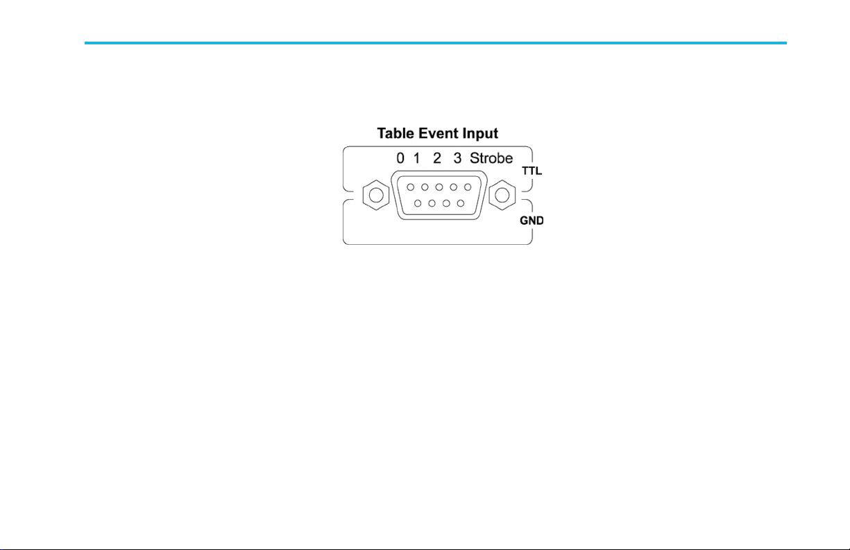
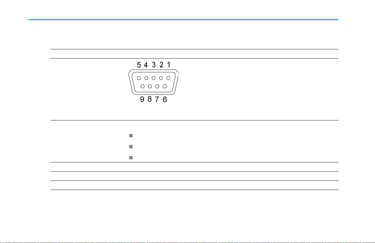
Table Event Input Connector
Connect an event signal to the Table Event Input conn ector.
Installation
The Table Event Input connector
accepts TTL-level signals from 0.0 V
to 5.0 V (DC + Peak AC). The
connector is a standard 9-pin D type.
By connecting the connector adapter
to your AWG5012B, the instrument
can accept four bit Table Jump signals.
TheTableJumpcandefine up to 16
possible logic levels of the Event Input
lines.
Pin NO.
1
2
3
4
5
6
7
8
9
Signal
STROBE
EVENT Bit3
EVENT Bit2
EVENT Bit1
EVENT Bit0
GND
GND
GND
GND
Direction
INPUT
INPUT
INPUT
INPUT
INPUT
TTL Event to TekLink LVDS Connector Adapter User Manual 3
Installation
Strobe Signal
You can input one strobe signal in addition to the four event signals. The strobe signal controls the tim ing of reading the event
signals.
When Strobe is set to Off, the instrument reads the event signals at the timing of every two internal clock cycles, and updates
the event value if a state transition in the event signals are found.
When Strobe is set to On, the instrument reads the event signals when the strobe signal goes to low state (Enable), and
updates the event value if a state transition in the event signals are found.
NOTE. You cannot toggle the Strobe signal on and off using th e screen interface or remote commands. The Strobe de finition in
the sequence file can control the strobe signal input. For more information abou t Strobe Signal and Sequence file, refer to
the user online help.
4 TTL Event to TekLink LVDS Connector Adapter User Manual
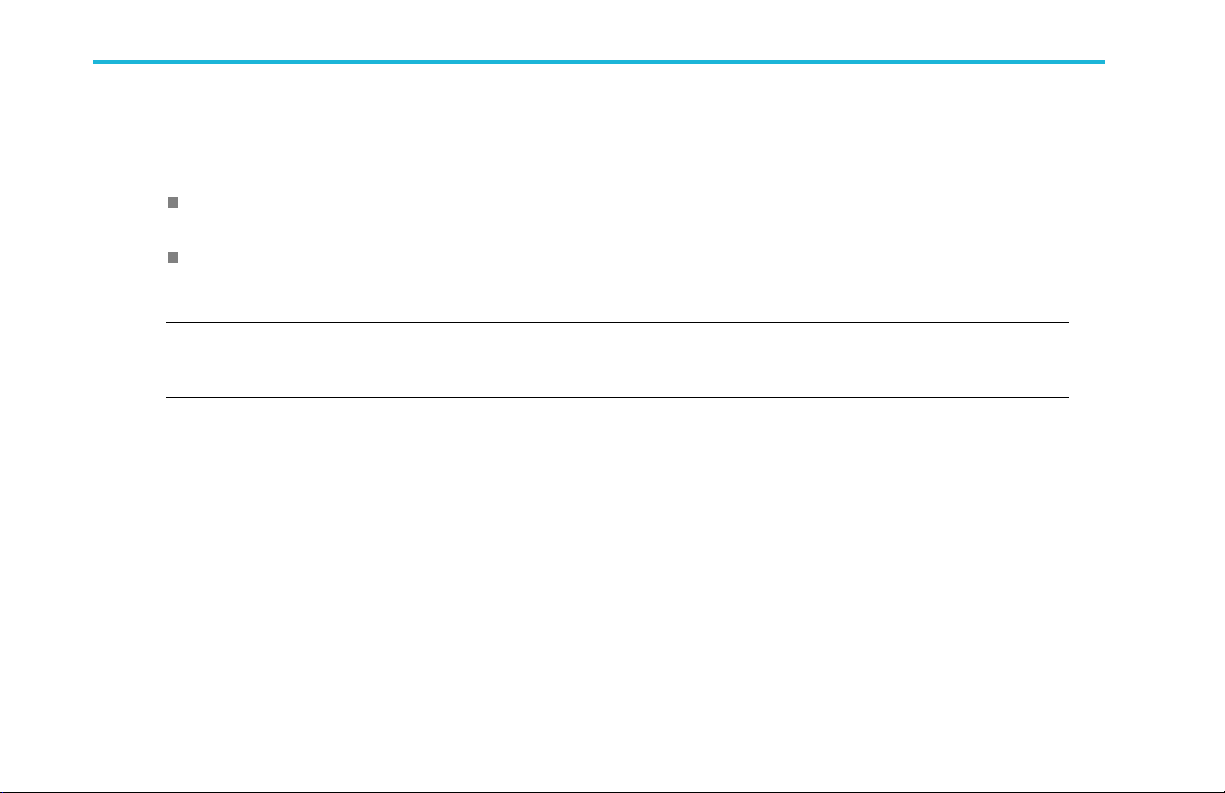
Connecting Cables
NOTE. Before connecting th e following cables, power off your instrument. Th e power is supplied from your AWG5012B through a
TekLink cable.
1. Connect a TTL-level signal to the Table
Event Input connector.
2. Use a TekLink cable to co nnect the
connector adapter and your AWG5012B.
Installation
TTL Event to TekLink LVDS Connector Adapter User Manual 5
Installation
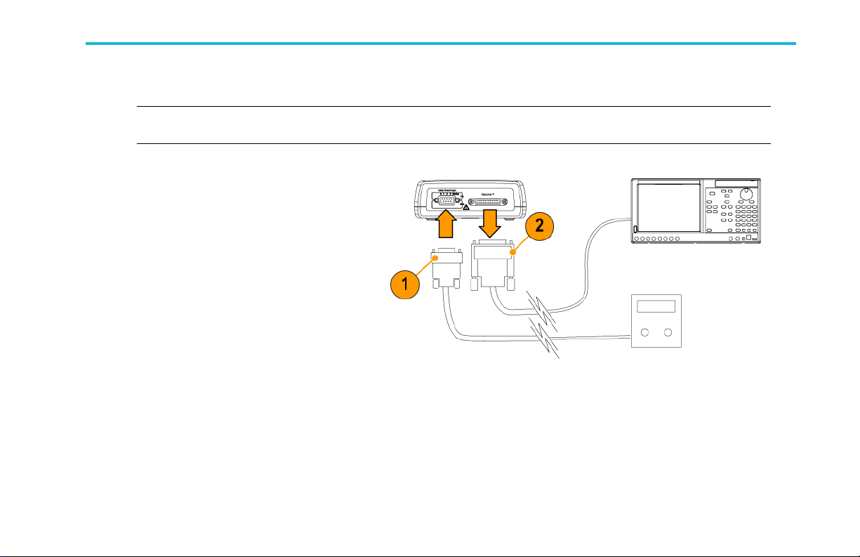
Mounting the Connector Adapter
You can mount the connector adapter to a surface, such as an existing rackmount tray, or to a bracket of your design, by doing
the following:
1. Remove the four adhesive-b acked, plastic
feet from the connector adapter.
2. Refer to the dimensions shown in the
illustration, and drill holes in the mounting
surface for two screws.
CAUTION. Using screws that are too long will
damage the internal circuitry. Screws should
enter the chassis ≤0.4 in. (1.03 cm).
3. Mount the connector adapter using two
6-32 screws of appropriate length.
NOTE. Some rackmou nt kits have provisions
for mounting accessories, such as the
connector adapter.
6 TTL Event to TekLink LVDS Connector Adapter User Manual

Specifications
Table Event Input (AWG5012B option 09)
Characteristic Description
Number of Event Jump
destination
Strobe On/Off selectable
Minimum pulse width 64 ns
Latency to analog output,
typical
Hold off time, typical Maximum 500 sample clock cycles (when Asynchronous Jump is selected)
Specifications
Up to 16
Max 650 ns @1.2 Gsps
Max 1300 ns @650 Msps
From D-type connector on the TTL to LVDS converter to An alog output when Asynchronous
Jump is selected
TTL Event to TekLink LVDS Connector Adapter User Manual 7
Specifications
TTL Event to LVDS TekLink Converter
Characteristic Description
Input con nector type
Input signals and pin
assignment
Input level TTL level
Input impedance
Output co
Output level LVDS
nnector type
9 pin, D-sub female
Input voltage range 0 V to 5 V
High-level input voltage 2 V to 5 V
Low-level input voltage 0 V to 0.8 V
Pull up to 4.5 V b y 2.2 kΩ register
40-pin TekLink connector
1
2
3
4
5
6
7
8
9
STROBE
3 (Event signal)
2 (Event signal)
1 (Event signal)
0 (Event signal)
Signal ground (GND)
Signal ground (GND)
Signal ground (GND)
Signal ground (GND)
8 TTL Event to TekLink LVDS Connector Adapter User Manual

Atmospherics
Characteristic Description
Temperature
Relative humidity
Altitude
Operating:
+10 °C to +40 °C
Nonoperating:
-20°Cto+60°C
Operating:
5% to 80% (no condensation), maximum wet-bulb temperature 29 °C
Nonoperating:
5% to 90% (no condensation), maximum wet-bulb temperature 29 °C
Operating:
Up to 3,000 m (approximately 10,000 feet)
Maximum o perating temperature decreases 1 °C each 300 m above 1.5 km
Nonoperating:
Up to 12,000 m (approximately 40,000 feet)
Physical characteristics
Characteristic Description
Height, typical
Width, typical
Depth, typical
Weight, typical
47.8 mm (1.882 in)
134.4 mm (5.291 in)
134.0 mm (5.275 in)
600g(1.32lb)
Specifications
TTL Event to TekLink LVDS Connector Adapter User Manual 9
 Loading...