


x
AWG5000 and AWG7000 Series
Arbitrary Waveform Generators
ZZZ
Quick Start User Manual
*P071248104*
071-2481-04


xx
AWG5000 and AWG7000 Series
Arbitrary Waveform Generators
ZZZ
Quick Start User Manual
www.tektronix.com
071-2481-04

Copyright © Tektronix. All rights reserved. Licensed software products are owned by Tektronix or its subsidiaries or suppliers, and are
protected by na
tional copyright laws and international treaty provisions.
Tektronix pro
previously published material. Specifications and price change privileges reserved.
TEKTRONIX and TEK are registered trademarks of Tektronix, Inc.
ducts are covered by U.S. and foreign patents, issued and pending. Information in this publication supersedes that in all
Contacting Tektronix
Tektronix, Inc.
14150 SW Karl Braun Drive
P.O. Box 500
Beaverton, OR 97077
USA
For product information, sales, service, and technical support:
In North America, call 1-800-833-9200.
Worldwide, visit www.tektronix.com to find contacts in your area.

Warranty
Tektronix warrants that this product will be free from defects in materials and workmanship for a period of one (1) year from the date of
shipment. If any such product proves defective during this warranty period, Tektronix, at its option, either will repair the defective
product without charge for parts and labor, or will provide a replacement in exchange for the defective product. Parts, modules and
replacement products used by Tektronix for warranty work may be new or reconditioned to like new performance. All replaced
parts, modules and products become the property of Tektronix.
In order to obtain service under this warranty, Customer must notify Tektronix of the defect before the expiration of the warranty period
and make suitable arrangements for the performance of service. Customer shall be responsible for packaging and shipping the
defective product to the service center designated by Tektronix, with shipping charges prepaid. Tektronix shall pay for the return of the
product to Customer if the shipment is to a location w ithin the country in which the Tektronix service center is located. Customer shall
be responsible for paying all shipping charges, duties, taxes, and any other charges for products returned to any other locations.
This warranty shall not apply to any defect, failure or damage caused by improper use or improper or inadequate m aintenance and
care. Tektronix shall not be obligated to furnish service under this warranty a) to repair damage resulting from attempts by personnel
other than Tektronix representatives to install, repair or service the product; b) to repair damage resulting from improper use or
connection to incompatible equipment; c) to repair any damage or malfunction caused by the use of non-Tektronix supplies; or
d) to service a product that has been modified or integrated with other products when the effect of such modification or integration
increases the time or difficulty of servicing the product.
THIS WARRANTY IS GIVEN BY TEKTRONIX WITH RESPECT TO THE PRODUCT IN LIEU OF ANY OTHER WARRANTIES,
EXPRESS OR IMPLIED. TEKTRONIX AND ITS VENDORS DISCLAIM ANY IMPLIED WARRANTIES OF MERCHANTABILITY OR
FITNESS FOR A PARTICULAR PURPOSE. TEKTRONIX' RESPONSIBILITY TO REPAIR OR REPLACE DEFECTIVE PRODUCTS
IS THE SOLE AND E XCLU S IVE REMEDY PROVIDED TO THE CUSTOMER FOR BREACH OF THIS WARRANTY. T EKT RONIX
AND ITS VENDORS WILL NOT BE LIABLE FOR ANY INDIRECT, SPECIAL, INCIDENTAL, OR CONSEQUENTIAL DAMAGES
IRRESPECTIVE OF WHETHER TEKTRONIX OR THE VENDOR HAS ADVANCE NOTICE OF THE POSSIBILITY OF SUCH
DAMAGES.
[W2 – 15AUG04]


Table of Contents
General Safety Summary ... ... . .. . ... . . .. . ... ... . .. . ... ... . .. . ... . .. . ... ... . .. . ... . . .. . ... ... . .. . ... . . .. . ... ... . .. . ... ... . .. . ... . .. .. iii
Compliance Information ............................................................................................................... v
EMC Compliance................................................................................................................. v
Safety Compliance ............................................................................................................... vi
EnvironmentalConsiderations.................................................................................................. vii
Preface ............................................................................................................................... viii
Key Features ................................................................................................................... viii
Documentation...................................................................................................................x
Conventions Used in this Manual . ... . .. . ... ... . .. . ... . .. . ... . .. . ... ... . .. . ... . .. . ... . .. . ... ... . .. . ... . .. . ... . .. . ... ... . .. . ... . . x
Installing Your Instrument ............................................................................................................. 1
Standard Accessories . ... . .. . ... . .. . ... ... . .. . ... . .. . ... ... . ... ... . .. . ... . .. . ... ... . .. . ... . .. . ... . .. . ... ... . .. . ... . . .. . ... ... . .. . 1
Operating Requirements ... . .. . ... . .. . ... ... . .. . ... . .. . ... . .. . ... ... . .. . ... . . .. . ... ... . .. . ... . .. . ... . .. . ... ... . .. . ... . . .. . ... ... . 2
Powering on the Instrument ..................................................................................................... 3
Powering off the Instrument ..................................................................................................... 4
Windows Interface Guidelines . . ... ... . ... ... . .. . ... . .. . ... ... . ... ... . .. . ... . .. . ... ... . ... ... . .. . ... . .. . ... ... . ... ... . .. . ... . .. . . 4
Connecting to a Network. . ... . .. . ... ... . .. . ... . .. . ... ... . .. . ... ... . .. . ... . .. . ... ... . .. . ... . . .. . ... ... . .. . ... . . .. . ... ... . .. . ... . . . 5
Setting GPIB/LAN................................................................................................................ 5
Controlling the Instrument Using a Remote PC................................................................................. 6
Offline Mode...................................................................................................................... 6
Inspecting Your Instrument ...................................................................................................... 7
Self Calibration ................................................................................................................... 8
Preventing InstrumentDamage ................................................................................................. 9
Option Installation............................................................................................................... 10
Creating Operating System Restore Discs .......................................................................................... 11
Creating Restore Discs ......................................................................................................... 11
Restoring the Instrument Operating System................................................................................... 11
Front P anel.. . .. . ... . .. . ... . .. . ... . . .. . ... ... . ... . . .. . ... ... . ... ... . .. . ... . .. . ... . .. . ... . .. . ... . .. . ... ... . ... ... . .. . ... . ... ... . ........ 13
Rear Panel (AWG7000C Series). ... . .. . ... ... . ... ... . .. . ... . ... ... . .. . ... . .. . ... . .. . ... . .. . ... . .. . ... . .. . ... . .. . ... . . .. . ... ... . ... . . 14
Dynamic Jump In Connector (AWG7000C Series) . . .. . ... . . .. . ... ... . .. . ... . .. . ... . .. . ... ... . ... ... . .. . ... . .. . ... . .. . ... ... . . 15
Rear Panel (AWG5000C Series). ... . .. . ... ... . ... ... . .. . ... . ... ... . .. . ... . .. . ... . .. . ... . .. . ... . .. . ... . .. . ... . .. . ... . . .. . ... ... . ... . . 16
ing Acquainted with Your Instrument ... . . .. . ... ... . .. . ... . . .. . ... ... . .. . ... . . .. . ... ... . .. . ... . . .. . ... ... . .. . ... . . .. . ... ... . .. . .. 18
Gett
Control Panel .. . ... ... . .. . ... . .. . ... . .. . ... ... . .. . ... . .. . ... . .. . ... . . .. . ... ... . .. . ... . .. . ... . .. . ... ... . ... ... . .. . ... . .. . ... . .. . ..18
Locking and Unlocking the Front Panel Controls . . . .. . ... ... . .. . ... . .. . ... . .. . ... ... . ... ... . .. . ... . .. . ... . .. . ... ... . .. . ... . .. . 19
Touch Screen Interface ......................................................................................................... 20
Elo Touchscreen Application. .. . ... ... . .. . ... ... . .. . ... . .. . ... ... . .. . ... ... . .. . ... . .. . .. . ... . .. . ... ... . .. . ... ... . .. . ... ... . .. . .. 20
Screen Interface.................................................................................................................21
Basic Steps for Using the Arbitrary Waveform Generator ... . .. . .. . ... . . .. . .. . ... ... . .. . ... ... . .. . .. . ... . .. . .. . ... ... . .. . ... .. 22
Run Mode ....................................................................................................................... 23
Accessing M enus and Control Windows . . .. . ... . .. . ... . .. . ... . . .. . ... ... . .. . ... . . .. . ... ... . ... ... . .. . ... . .. . ... ... . ... ... . .. . . 24
Changing Control Settings ... . .. . ... ... . .. . ... . .. . ... . .. . ... ... . .. . ... . .. . ... . .. . ... ... . .. . ... . .. . ... . .. . ... ... . .. . ... . .. . ... . .. 25
Display/Hide Control Windows . ... . .. . ... . .. . ... ... . ... ... . .. . ... . . .. . ... ... . .. . ... . . .. . ... ... . .. . ... . . .. . ... ... . .. . ... . . .. . ... 26
Status Bar .......................................................................................................................27
Table of Content
s
AWG5000 and AWG7000 Series Quick Start U ser Manual i

Table of Content
Saving and Recalling Setups......................................................................................................... 40
Waveform Display and Edit ..........................................................................................................50
Sequence .. . .. . ... . .. . ... . .. . ... ... . .. . ... . .. . ... . .. . ... ... . .. . ... . .. . ... . .. . ... ... . .. . ... . .. . ... . .. . ... ... . .. . ... . .. . ... . .. . ... ...... 68
Tutorials............................................................................................................................... 79
Index
s
Setting the User Preferences................................................................................................... 28
Changing the Wi
Run State Control and Output On/Off.......................................................................................... 30
Setting Output Signals . . .. . ... ... . .. . ... ... . .. . ... ... . .. . ... ... . .. . .. . ... . .. . .. . ... . .. . .. . ... ... . .. . ... ... . .. . ... ... . .. . ... ... . . 32
Interleave ........................................................................................................................ 36
Digital Output (Option 03)....................................................................................................... 39
File Menu........................................................................................................................40
Saving an Instrument Setup.................................................................................................... 41
Recalling an Instrument Setup ................................................................................................. 42
Default Set
Changing Settings at Power-On .. . .. . ... . .. . .. . ... . .. . .. . ... . .. . ... ... . .. . ... . . .. . ... ... . .. . ... ... . .. . ... . .. . .. . ... . .. . ... ... . . 43
Importing Waveform Data....................................................................................................... 44
Exporting
Waveform Window .. . ... ... . .. . ... . .. . ... . .. . ... ... . .. . ... . .. . ... . .. . ... . . .. . ... ... . .. . ... . .. . ... . .. . ... ... . ... ... . .. . ... . .. . ... 50
Using Zoo
Creating or Modifying a Waveform............................................................................................. 52
Creating a Standard Waveform. .. . ... ... . .. . ... ... . .. . ... . .. . ... ... . .. . ... . . .. . ... ... . .. . ... . . .. . ... ... . .. . ... . . .. . ... ... . .. . .. 53
Equation
Accessing Waveform in a Setup File........................................................................................... 56
Changing a User-Defined Waveform Name ................................................................................... 57
Confirmi
Editing a Waveform ............................................................................................................. 58
Math Waveforms ................................................................................................................ 61
Normal
Using Other Edit Menu Commands . ... . .. . ... . .. . ... . . .. . ... ... . ... ... . .. . ... . ... ... . .. . ... . .. . ... . .. . ... . .. . ... . . .. . ... ... . .. 62
Seque
Creating a Sequence .. . .. . ... . .. . ... . .. . ... ... . .. . ... . .. . ... . .. . ... ... . .. . ... . .. . ... . .. . ... ... . .. . ... . .. . ... . .. . ... ... . .. . ... . . 70
Creating a Subsequence .. . ... . .. . ... ... . .. . ... . .. . ... . .. . ... ... . .. . ... . . .. . ... ... . .. . ... . .. . ... . .. . ... ... . .. . ... . . .. . ... ... . .. 72
Editi
Event Jump...................................................................................................................... 76
Force Jump To .................................................................................................................. 77
Acce
Creating and Editing a Waveform .............................................................................................. 79
Cre
ng Waveform Properties ... . .. . .. . ... . .. . ... ... . .. . ... ... . .. . ... ... . .. . ... ... . .. . ... ... . .. . ... . .. . .. . ... ... . .. . ... . . .. . 57
ize Option................................................................................................................ 62
nce W indow . . .. . ... . .. . ... . . .. . ... ... . ... ... . .. . ... . .. . ... . .. . ... . . .. . ... ... . ... ... . .. . ... . .. . ... . .. . ... . . .. . ... ... . ... .. 68
ng a Sequence . . ... . .. . ... . .. . ... ... . .. . ... . .. . ... . .. . ... ... . ... ... . .. . ... . .. . ... . .. . ... . . .. . ... ... . .. . ... . .. . ... . .. . ... ... 74
ssing Sequence Elements Outside the Display Area . . .. . ... ... . .. . ... ... . .. . ... . .. . ... ... . .. . ... ... . .. . ... . .. . ... ... . .. 78
ating and Editing a Sequence .. . .. . ... . .. . ... ... . .. . ... . .. . ... ... . ... ... . .. . ... . . .. . ... ... . .. . ... . .. . ... ... . ... ... . .. . ... . . 81
ndows Display Style . . .. . ... . .. . ... ... . ... ... . .. . ... . .. . ... ... . .. . ... . .. . ... . .. . ... ... . .. . ... . . .. . ... ... . .. . .. 29
up.................................................................................................................... 43
Waveform Data ...................................................................................................... 48
m ..................................................................................................................... 51
Editor .................................................................................................................. 55
ii AWG5000 and AWG7000 Series Quick Start User Manual

General Safety S
ummary
General S afet
Review the following safety precautions to avoid injury and prevent damage to this product or any products connected to it.
To avoid potential hazards, use this product only as specified.
Only qualified personnel should perform service procedures.
To Avoid Fire or Personal Injury
Use proper power cord. Use only the power cord specified for this product and certified for the country of use.
Ground the product. This product is grounded through the grounding conductor of the power cord. To avoid electric
shock, the grounding conductor must be connected to earth ground. Before making c onnections to the input or output
terminals
Observe al
product manual for further ratings information before making connections to the product.
Do not apply a potential to any terminal, including the common terminal, that exceeds the m aximum rating of that terminal.
Power disconnect. The power cord disconnects the product from the power source. D o not block the power cord; it
must remain accessible to the user at all times.
Do not operate without covers. Do not operate this product with covers or panels removed.
Do not operate with suspected failures. If you suspect that there is damage to this product, have it inspected by
qualifie
of the product, ensure that the product is properly grounded.
lterminalratings.
d service personnel.
y Summary
To avoid fire or shock hazard, observe all ratings and markings on the product. Consult the
Avoid e
xposed circuitry.
Do not touch exposed connections and components when power is present.
Do not operate in wet/damp conditions.
Do not operate in an explosive atmosphere.
Keep product surfaces clean and dry.
ide proper ventilation.
Prov
proper ventilation.
Refer to the manual's installation instructions for details on installing the product s o it has
AWG5000 and AWG7000 Series Quick Start User M anual iii
General Safety S
Terms in This Manu al
These terms may appear in this manual:
WARNING. Warning statements identify conditions or practices that could result in injury or loss of life.
CAUTION. Caution statements identify conditions or practices that could result in damage to this product or other property.
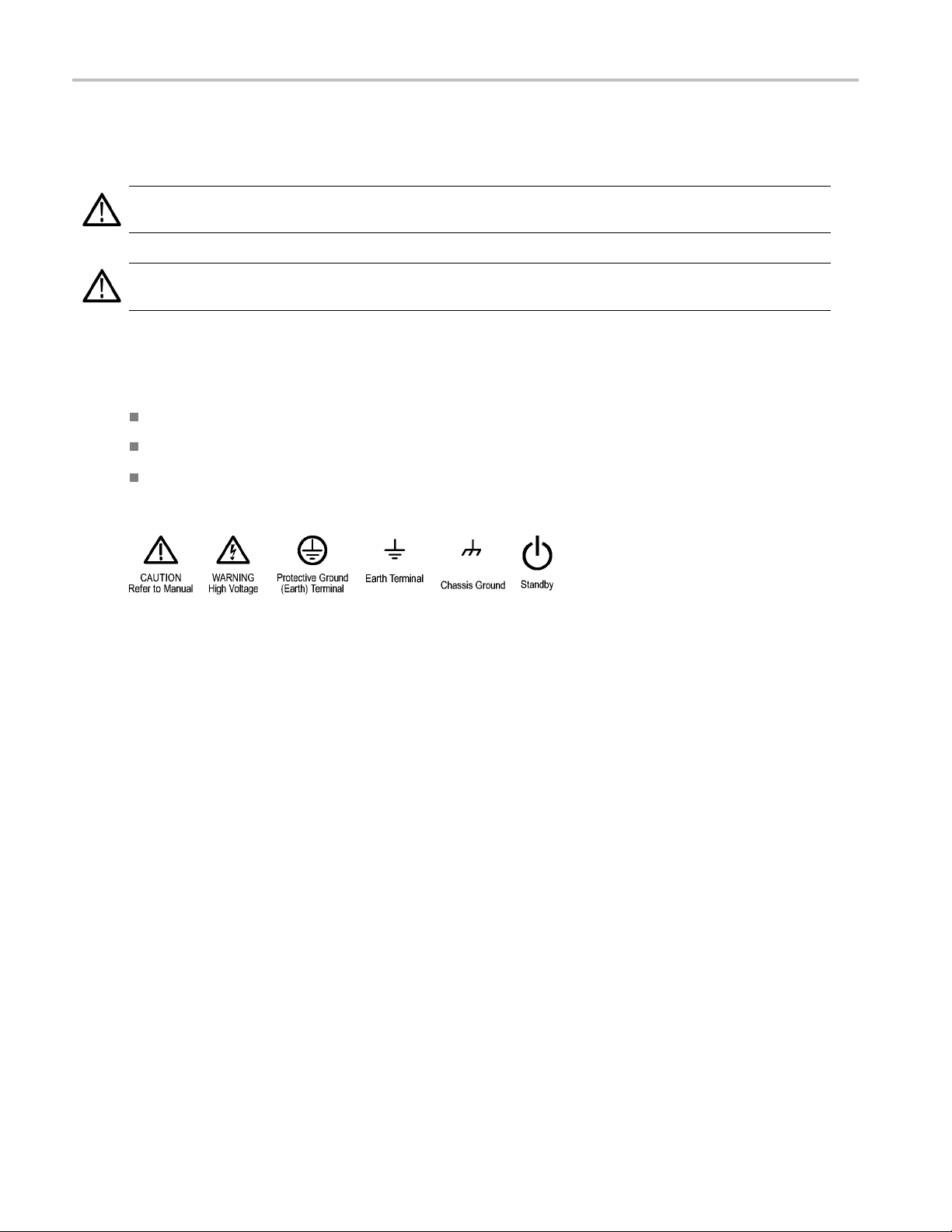
Symbols and Terms on the Product
These terms may appear on the product:
DANGER indicates an injury hazard immediately accessible as you read the marking.
WARNING indicates an injury hazard not immediately accessible as you read the marking.
CAUTION indicates a hazard to property including the product.
The following symbol(s) may appear on the product:
ummary
iv AWG5000 and AWG7000 Series Quick Start User Manual

Compliance Info
rmation
Compliance In
This section lists the EMC (electromagnetic compliance), safety, and environmental standards with which the instrument
complies.
EMC Compliance
EC Declarati
Meets intent of Directive 2004/108/EC for E lectromagnetic Compatibility. Compliance was demonstrated to the following
specifications as listed in the Official Journal of the European Communities:
EN 61326-1 2006. EMC requirements for electrical equipment for measurement, control, and laboratory use.
CISPR 11:2003. Radiated and conducted emissions, Group 1, Class A
IEC 61000-4-2:2001. Electrostatic discharge immunity
IEC 61000-4-3:2002. RF electromagnetic field immunity
IEC 61000-4-4:2004. Electrical fast transient / burst immunity
IEC 61000-4-5:2001. Power line surge immunity
IEC 61000-4-6:2003. Conducted RF immunity
on of Conformity – EMC
formation
123
IEC 61000-4-11:2004. Voltage dips and interruptions immunity
EN 61000-3-2:2006. AC power line harmonic emissions
EN 61000-3-3:1995. Voltage changes, fluctuations, and flicker
ean contact.
Europ
Tektronix UK, Ltd.
Western Peninsula
Western Road
Bracknell, RG12 1RF
United Kingdom
1
2
3
product is intended for use in nonresidential areas only. Use in residential areas may cause electromagnetic interference.
This
Emissions which exceed the levels required by this standard may occur when this equipment is connected to a test object.
To ensure compliance with the EMC standards listed here, high-quality shielded interface cables should be used.
AWG5000 and AWG7000 Series Quick Start U ser Manual v

Compliance Info
rmation
Australia / New Zealand Declaration of Conformity – EMC
Complies with the EMC provision of the Radio communications Act per the following standard, in accordance with ACMA:
CISPR 11:2003. Radiated and Conducted Emissions, Group 1, Class A, in accordance with EN 61326-1:2006.
Safety Compliance
EC Declarati
Compliance w as demonstrated to the following specification as listed in the Official Journal of the European Communities:
Low Voltage Directive 2006/95/EC.
EN 61010-1: 2001. Safety requirements for electrical equipment for measurement control and laboratory use.
on of Conformity – Low Voltage
U.S. Nationally Recognized Testing Laboratory Listing
UL 61010-
1:2004, 2
nd
Edition. Standard for electrical measuring and test equipment.
Canadian Certification
CAN/CSA-C22.2 No. 61010-1:2004. Safety requirements for electrical equipment for measurement, control, and
laboratory use. Part 1.
Additional Compliances
IEC 61010-1: 2001. Safety requirements for electrical equipment for measurement, control, and laboratory use.
ment Type
Equip
Test and measuring equipment.
Safety Class
ss 1 – grounded product.
Cla
Pollution Degree Description
A measure of the contaminants that could occur in the environment around and within a product. Typically the internal
environment inside a product is considered to be the same as the external. Products should be used only in the environment
for which they are rated.
Pollution Degree 1. No pollution or only dry, nonconductive pollution occurs. Products in this category are generally
encapsulated, hermetically sealed, or located in clean rooms.
Pollution Degree 2. Normally only dry, nonconductive pollution occurs. Occasionally a temporary conductivity that is
caused by condensation m ust be expected. This location is a typical office/home environment. Temporary condensation
occurs only when the product is out of service.
vi AWG5000 and AWG7000 Series Quick Start User Manual
Compliance Info
Pollution Degree 3. Conductive pollution, or dry, nonconductive pollution that becomes conductive due to condensation.
These are shelt
sunshine, rain, or direct wind.
Pollution Degree 4. Pollution that generates persistent conductivity through conductive dust, rain, or snow. Typical
outdoor locations.
ered locations where neither temperature nor humidity is controlled. The area is protected from direct
rmation
Pollution De
Pollution Degree 2 (as defined in IEC 61010-1). Note: Rated for indoor use only.
gree
Environmental Considerations
This secti
Product End-of-Life Handling
Observe the following guidelines when recycling an instrument or component:
Equipment recycling. Production of this equipment required the extraction and use of natural resources. The equipment may
contain s ubstances that could be harmful to the environment or human health if improperly handled at the product’s end of life. In
order to avoid release of s uch substances into the environment and to reduce the use of natural resources, we encourage you to
recycle this product in an appropriate syste m that will ensure that most of the materials are reused or recycled appropriately.
Mercury notification. This product uses an LCD backlight lamp that contains mercury. Disposal may be regulated due to
envir
Web page (www.eiae.org) for disposal or recycling information.
1
on provides information about the environmental impact of the product.
This symbol indicates that this product c omplies w ith the applicable European Union requirements according
to Directives 2002/96/EC and 2006/66/EC on waste electrical and electronic equipment (WEE E) and
batteries. For information about recycling options, check the Support/Service section of the Tektronix Web
site (www.tektronix.com).
onmental considerations. Please contact your local authorities or, within the United States, refer to the E-cycling Central
Mercury notification does not apply to AWG5000C or AWG7000C series instruments.
1
Perchlorate materials. This product contains one or more type CR lithium batteries. According to the state
lifornia, CR lithium batteries are classified as perchlorate materials and require special handling. See
of Ca
www.dtsc.ca.gov/hazardouswaste/perchlorate for additional information.
Restriction of Hazardous Substances
This product has been classified as Monitoring and Control equipment, and is outside the scope of the 2002/95/EC RoHS
Directive.
AWG5000 and AWG7000 Series Quick Start User Manual vii

Preface
Preface
This manual describes the installation and operation of AWG5000 and AWG7000 series instruments. Basic operations and
concepts are presented in this manual. For more detailed information, see the online help on your instrument. The following
instruments are supported by this manual:
AWG7000C Series: AWG7122C AWG7082C
AWG5000C Series: AWG5002C, AWG5012C, AWG5014C
AWG7000B Series: AWG7121B, AWG7122B, AWG7061B, AWG7062B
AWG5000B Series: AWG5012B, AWG5014B, AWG5002B, AWG5004B
Key Features
The follow
Microsoft
Microsof
Extended
28-bit di
Interle
Fast seq
A large 1
An intu
Remova
Suppor
LAN (1
Touch
ing list describes some of the key features of the AWG5000 and AWG7000 series instruments:
Windows 7 Professional operating system, AWG5000C and AWG7000C series
t Windows XP Professional operating system, AWG5000B and AWG7000B series
analog output bandwidth (Option 02 and Option 06)
gital data output (Option 03), AWG5002B, AWG5012B, AWG5002C, and AWG5012C only
ave and extended analog output bandwidth (Option 06), AWG7122B, AWG7122C, and AWG7082C only
uence switching (Option 08), AWG5000B series, AWG7000B series, and AWG7000C series only
0.4 inch (264.2 mm) high resolution XGA color display
itive, graphical user interface , with built-in online help
ble hard disk drive (Option 05)
ts USB 2.0 interface
000/100/10 Base-T)
screen user interface
viii AWG5000 and AWG7000 Series Quick Start User Manual

Table i: AWG5000C and AWG7000C features
Model AWG7122C AWG7082C AWG5014C AWG5012C AWG5002C
Maximum
sampling rate
D/A resolution 8 bits or 10 bits (selectable)
Waveform
length
Analog output 2 2 4 2 2
Marker output 4 4 8 4 4
Maximum
analog
amplitude
Maximum
amplitude
and analo
g
bandwidth
Digital data
output
12 GS/s
(24 GS/s by
8 GS/s (16 GS/s
by interleave)
1.2 GS/s 1.2 GS/s 600 MS/s
interleave)
14 bits
32 M or 64 M (Option 01) 16 M or 32 M (Option 01)
2V
(standard model)
pp
1V
(Option 06)
pp
2 Vp-p, 750 MHz (Normal mode)
1 Vp-p, 3.
5 GHz (Direct D/A mode)
2 Vp-p, 250 MHz (Normal mode)
0.6 Vp-p,
4.5 V
pp
370 MHz (Direct D/A mode)
1 Vp-p, 7.5 G Hz (Option 02
or Option 06)
N/A N/A N/A
28 bits
(Option 03)
28 bits
(Option 03)
Preface
Table ii: AWG5000B and AWG7000B features
1B/
AWG501
AWG5014B
Model
Maxim
rate
um sampling
AWG712
1B/
AWG7122B
12 G S /s (24 GS/s by
interleave)
AWG706
AWG7062B
6 GS/s 1.2 GS/s 600 MS/s
D/A resolution 8 bits or 10 bits (selectable)
Waveform length 32 M or 64 M (Option 01) 16 M or 32 M (Option 01)
Analog output 1 or 2 2 or 4
imum analog
Max
amplitude
Maximum amplitude
and analog
ndwidth
ba
arker output
M
1
1 Vp-p, 7.5 GHz (O ption 02 or Option 06)
Digital data output
1
When 10 bits DAC resolution is selected in the AWG7000 series, Marker Output is disabled.
2V
(standard model)
pp
1V
(Option 06)
pp
2 Vp-p, 750 MHz (Normal mode)
p-p, 3.5 GHz (Direct D/A mode)
1V
or 4
2
/A
N
2B/
AWG500
AWG5004B
14 bits
V
4.5
pp
2 Vp-p, 250 MHz (Normal mode)
6 Vp-p, 370 MHz (Direct D/A mode)
0.
or 8
4
8 bits (Option 03)
2
2B/
AWG5000 and AWG7000 Series Quick Start User Manual ix
Preface
Documentation
Review the following table to locate more information about this product.
To read about Use these documents
Installation and operation (overviews) Read the Quick Start User Manual for general information about how to
In-depth operation and user interface help Access the user online help from the Help menu for information on
Programmer commands
Specifications and performance verification
procedures
Service procedures
use your instrument.
virtually all controls and elements on screen. Online help includes detailed
instructions for using instrument functions.
Access the programmer online guide from the Help menu. The
programmer guide includes the syntax of remote commands.
Read the technical reference documents for specifications and the
performance verification procedures. T hese documents are available on
the documentation CD.
Read the service manuals to service instruments to the module
level. The service manuals are available on the Tektronix Web site
(www.tektronix.com/manuals).
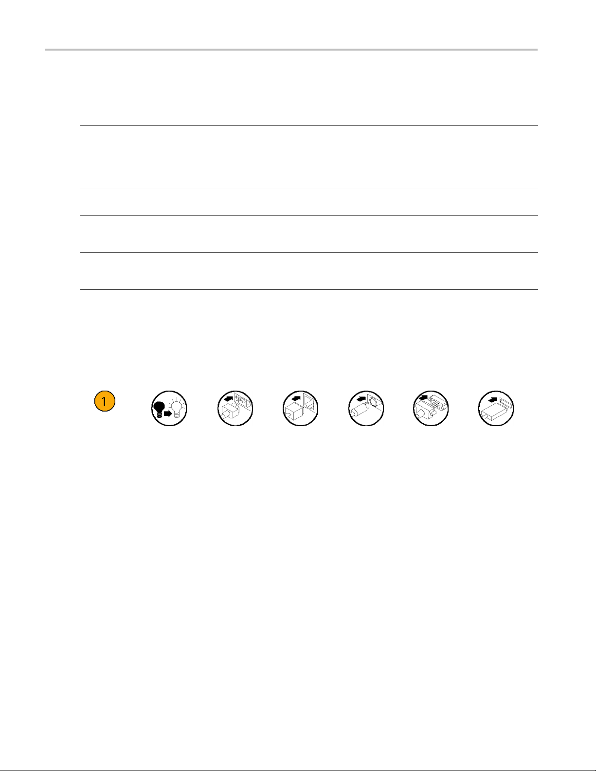
Conventions Used in this Manual
The following icons are used throughout this manual.
Sequence
Step
Front panel
power
Connect
power
Network
PS2 SVGA USB
x AWG5000 and AWG7000 Series Quick Start User Manual

Installing Your Instrument
Unpack the instrument and check that you received all items listed as Standard Accessories. Check the Tektronix Web
site (www.tektronix.com) for the most current information.
NOTE. The instrument does not ship with a product software CD. To reinstall the product software, go to the Tektronix Web
site and download the latest product software for your instrument.
Standard Accessories
Accessory Tektronix part number
AWG5000B and AWG7000B Series Quick Start User Manual
English (Option L0)
Japanese (Option L5)
Simplified Chinese (Option L7)
Traditional Chinese (Option L8)
Russian (Option L10)
Documentation CD
User Online Help (part of the product software)
Programmer Online Help (part of the product software)
Windows compatible keyboard 119-7083-xx
Windows compatible mouse 119-7054-xx
Lead Set for DC Output
Front Protect C over
Accessory Pouch 016-1441-xx
50 Ω SMA Termination, Male, DC to 18 GHz (3 each)
(AWG7000 series only)
Power cord – one of the following:
North America (Option A0)
Universal Euro (Option A1)
United Kingdom (Option A2)
Australia (Option A3)
Switzerland (Option A5)
Japan (Option A6)
China (Option A10)
India (Option A11)
No power cord or AC adapter
(Option A99)
071-2481-xx
071-2482-xx
071-2483-xx
071-2484-xx
020-2971-xx
063-4134-xx
---
---
012-1697-xx
200-4963-xx
015-1022-xx
Installing Your
Instrument
AWG5000 and AWG7000 Series Quick Start U ser Manual 1
Installing Your
Instrument
Operating Requirements
CAUTION. To e n
Place the instrument on a cart or bench, observing clearance requirements:
Top: 20 mm (0.8 in)
Left and right side: 150 mm (5.9 in)
Bottom: 20 mm (0.8 in)
Rear: 75 mm (3 in)
Environmental Req
Before operating the instrument, ensure that the instrument has warmed up for 20 minutes and meets the environmental
requirements lis
Requirement Description
Temperature (op
Relative humid
Altitude (ope
sure proper cooling, keep sides of the instrument clear of obstructions.
uirements
ted in the following table.
erating)
ity (operating)
rating)
10 °C to 40 °C (+50
5% to 95% relati
5% to 45% relative humidity above 30 °C (86 °F) up to
+40 °C (104 °F) noncondensing, and as limited by a
maximum wet-bu
Up to 3,000 m (a
°F to +104 °F)
ve humidity at up to 30 °C (86 °F)
lb temperature of 29 °C (84.2 °F)
pproximately 10,000 feet)
Power Supply Requirements
WARNING. To r
operating voltage range.
Source Voltage and
100 VAC to 240 VAC,
educe the risk of fire and shock, ensure that the mains supply voltage fluctuations do not exceed 10% of the
Frequency
47 Hz to 63 Hz
Power Consumption
Less than 450 W (AW
Less than 560 W (AWG5000 series)
G7000 series)
2 AWG5000 and AWG7000 Series Quick Start User Manual
Cleaning
Installing Your
Instrument
WARNING. To a v
the following procedures.
Inspect the arbitrary waveform generator as often as operating conditions require. To clean the exterior surface, perform
the following steps:
1. Remove loose dust on t
2. Use a soft cloth damp
CAUTION. To avoid damage to the surface of the arbitrary waveform generator, do not use any abrasive or chemical
cleaning agents.
oid personal injury, power off the instrument and disconnect it from line voltage before performing any of
he outside the instrument with a lint-free cloth. Use care to avoid scratching the front panel display.
ened with water to clean the instrument. Use a 75% isopropyl alcohol solution as a cleaner.
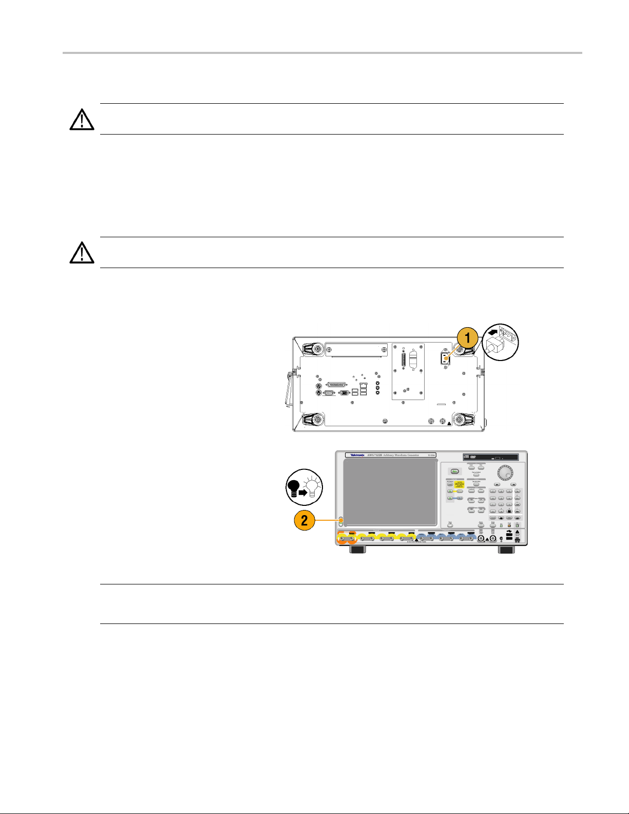
Powering on the Instrument
1. Connect the AC power cord t
the instrument.
o the rear of
2. Use the front-panel po
switch the instrument on.
NOTE. Before using the instrument, create a set of operating system restore discs, to provide a back-up of the system.
The instrument doe
(See page 11, Creating Operating System Restore Discs.)
wer button to
s not ship with operating restore media. Refer to the instructions to create the operating restore discs.
AWG5000 and AWG7000 Series Quick Start U ser Manual 3
Installing Your
Instrument
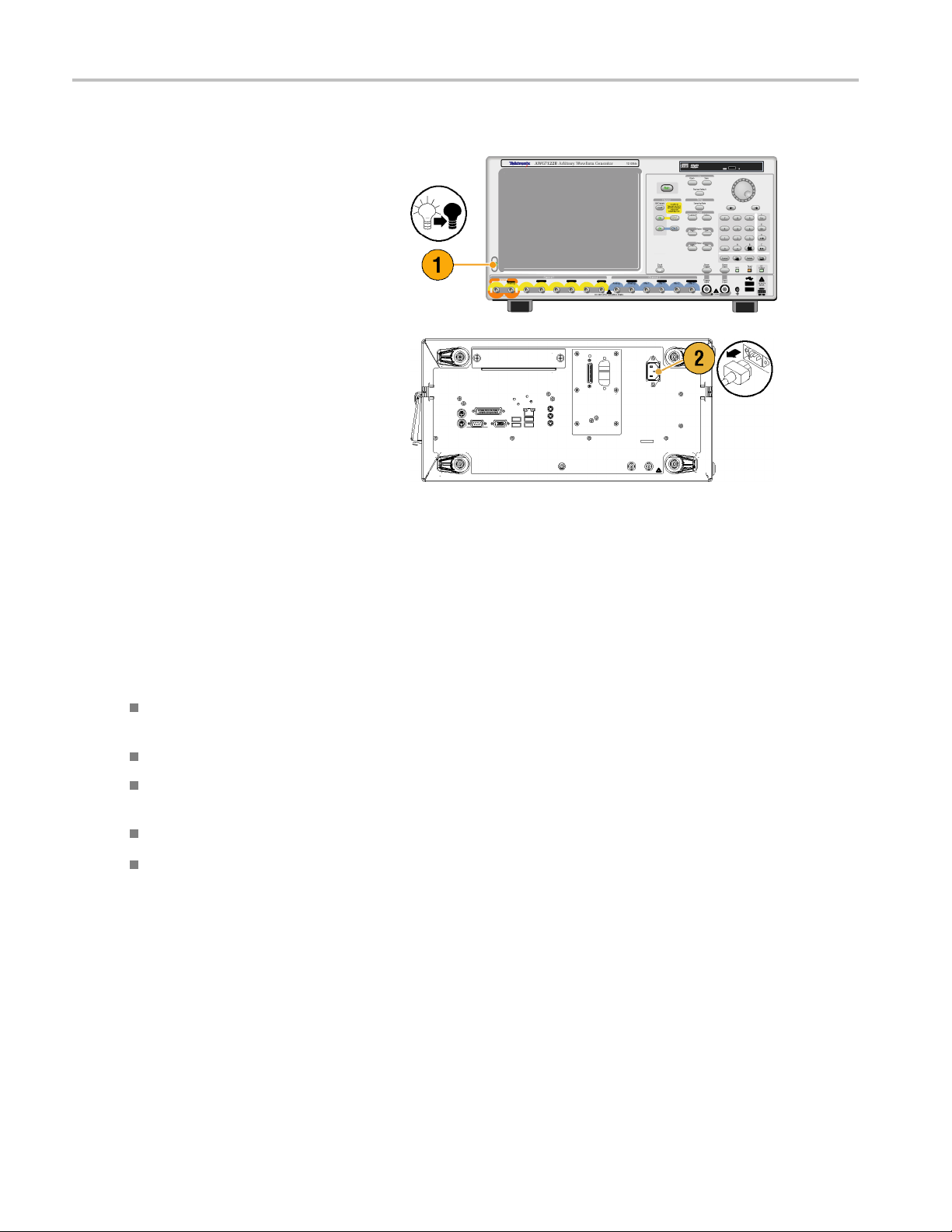
Powering off the Instrument
1. Use the front-
the shutdown process.
Wait approximately 30 seconds for the
instrument t
2. To com p le te
instrument, perform the shutdown just
described, and then remove the power
cord from t
panel power button to start
o power off.
ly remove power to the
he instrument.
Windows Interface Guidelines
Because the instrument uses the Microsoft Windows interface, you have open access to the W indows operating system. You
can access the Windows desktop to load and run other Windows-based applications such as Microsoft Excel, WordPad, and
Paint.
Follow these guidelines to avoid making operating system changes that might cause problems or annoyances while trying to
use the instrument:
Be careful when making changes in the Control Panel. Avoid making changes to any controls with which you are
unfamiliar.
Do not delete or change any system fonts; this can affect the quality of the display.
Do not change the system Display Properties, such as the Background, Appearance, Effects, or S e ttings. Making such
changes can affect the usability of the instrument and the touch screen.
Do not change the contents of the Windows folder or the Program Files\Tektronix\AWG\ System folder.
Do not change the BIOS settings; this can affect the overall operation of the instrument.
If you think that your Windows interface might cause problems with the instrument, contact your local Tektronix support
center for assistance.
4 AWG5000 and AWG7000 Series Quick Start User Manual
Connecting to a Network
You can connect your instrument to a network for printing, file sharing, Internet access, and other functions. Consult with
your network administrator and use the standard Windows utilities to configure the instrument for your network. For setting
GPIB or LAN configuration, use the GP IB/LAN Configuration dialog box from System menu.
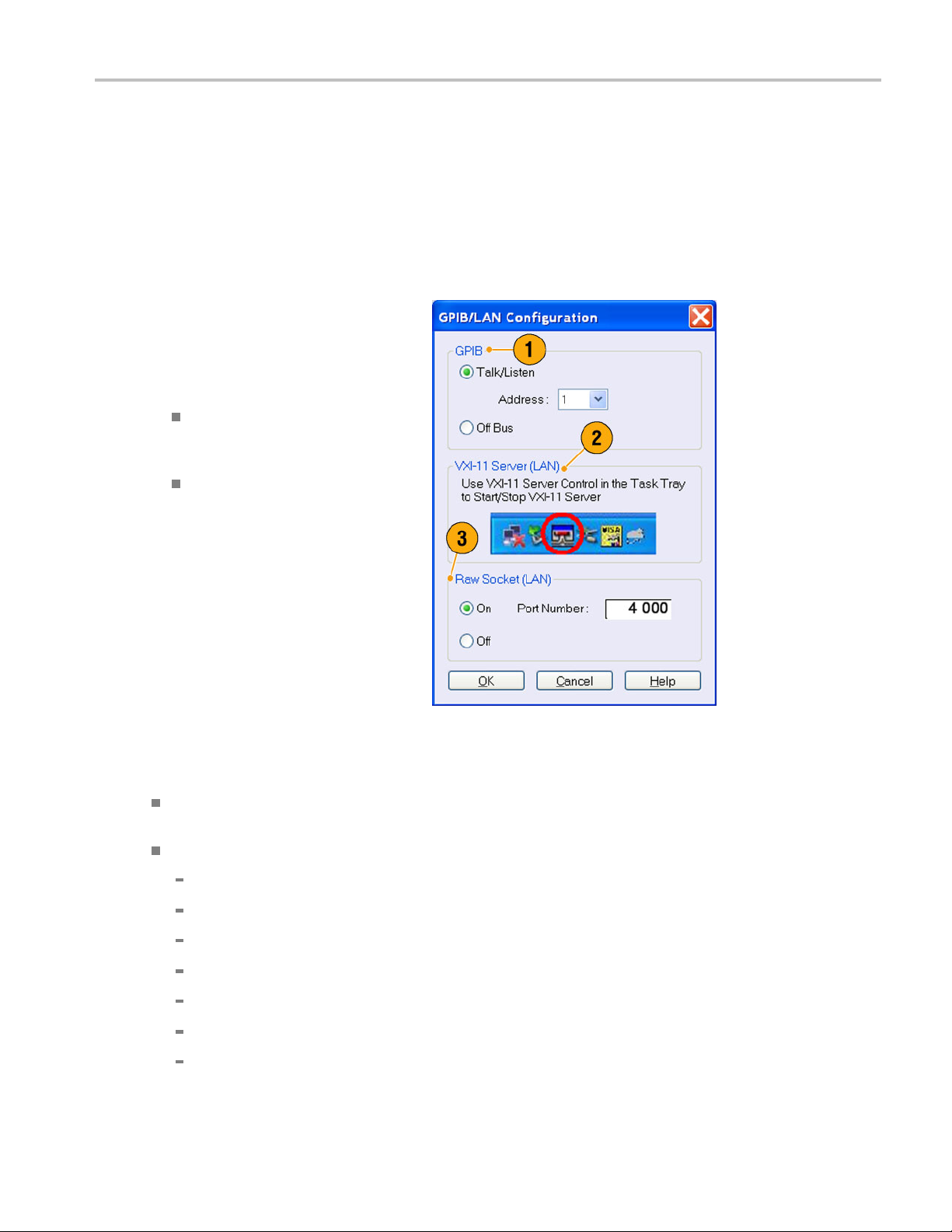
Setting GPIB/LAN
Select System > GPIB/LAN Configuration
to open the GPIB/LAN Configuration dialog
box.
1. Set the instrument GPIB bus
communication:
Talk/Listen – Select this mode to
remotely control the instrument from
an external host computer.
Off Bus – Select this mode to
disconnect the instrument from the
GPIB bus.
Installing Your
Instrument
2. The instrument supports the VXI-11
Server (LAN). Use VXI-11 Server Control
in the Task Tray to Start/Stop VXI-11
Server.
3. TCP/IP protocol is also supported. On
and Off of socket communication are
controlled here. The port number is fixed
to 4000.
Quick Tip
To start the VXI-11 Server automatically at power-on, check the "Start server automatically at system power on " check
box in the VXI-11 Server Control.
The following operations cannot be performed through a GPIB or LAN connection:
Editing a waveform
Changing size or name of waveform
Converting the w aveform format
Importing waveform data from the AWG5000 series and AWG7000 series setup (*.AWG) file
Importing a Tektronix DTG5000 series file (*.DTG)
Importing a Tektronix AWG400/500/600/700 series SEQ file
Exporting waveform data
AWG5000 and AWG7000 Series Quick Start U ser Manual 5
Installing Your
Instrument
Controlling the Instrument Using a R emote PC
You can use your PC to control the arbitrary waveform generator through a LAN using the Windows Remote Desktop
function. If your PC has a larger screen, you can edit waveforms easily using your keyboard and mouse. You can also use a
third party software installed on your PC to create a waveform and import it through a network.
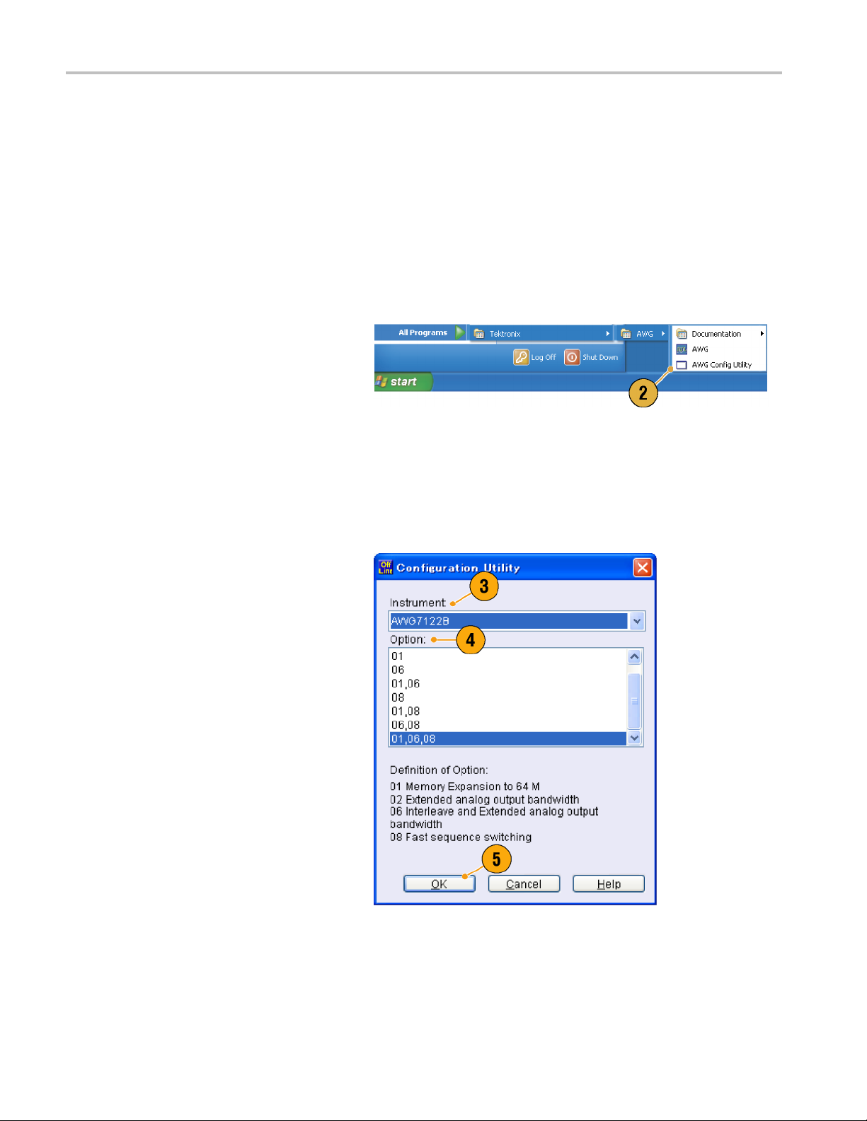
Offline Mode
The Offline Mode is a function that you can use to run the instrument application on your PC. Install the application on your
PC; the instrument hardware is not required. You can create and edit the instrument setups. The setup files that you create
can be used l
1. Go to the Tektronix Web site
(www.tektronix.com/software) and
download t
Product Software. Follow the instructions
to install the AWG application on your
PC.
ater with your arbitrary waveform generator.
he latest version of the AWG
2. Before us
set up the instrument con figuration.
From the Windows Start menu, select All
Program
Utility.TheConfiguration Utility dialog
box appears.
3. Select your instrument type.
4. Select your instrument option
configu
5. Click
Run the instrument application from the
Start menu. The setup configuration you
have m
will be reflected in the application.
ing the offline mode, you must
s > Tektronix > AWG > Config
ration.
OK.
ade using the Configuration Utility
6 AWG5000 and AWG7000 Series Quick Start User Manual
Inspecting Your Instrument
Two types of diagnostics are provided to verify the functionality of your instrument:
Power-on self test – Every time you power on the instrument, the instrument automatically performs the internal
diagnostics.
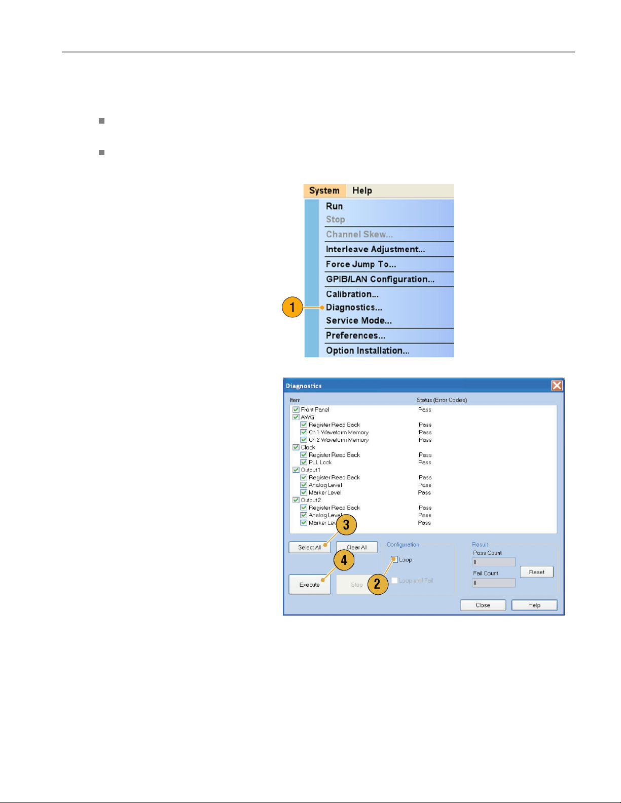
Diagnostics from the System menu – You can also run the internal diagnostics using the System menu. Use the
following procedures:
1. Select System > Diagnostics from the
menu bar.
The Diagnostics dialog box appears.
Installing Your
Instrument
2. Confirm that the Loop box is not
checked.
If Loop is checked, the diagnostics runs
until it is manually stopped.
3. If you click Select All, all diagnostic
items are checked.
You can execute all items together or you
can execute only the selected item(s).
4. Click Execute to start the diagnostics.
Verify that the instrument passes all
tests. If diagnostic failures occur, contact
your local Tektronix service personnel.
AWG5000 and AWG7000 Series Quick Start U ser Manual 7
Installing Your
Instrument
Self Calibration
The self calibration uses internal calibration routines that check electrical characteristics such as analog level and marker
level, and then adjust the internal calibration constants as necessary. Marker level is checked only in the AWG7000 series
instruments.
NOTE. Power on the instrument and allow a 20 minute warm-up period before performing this procedure.
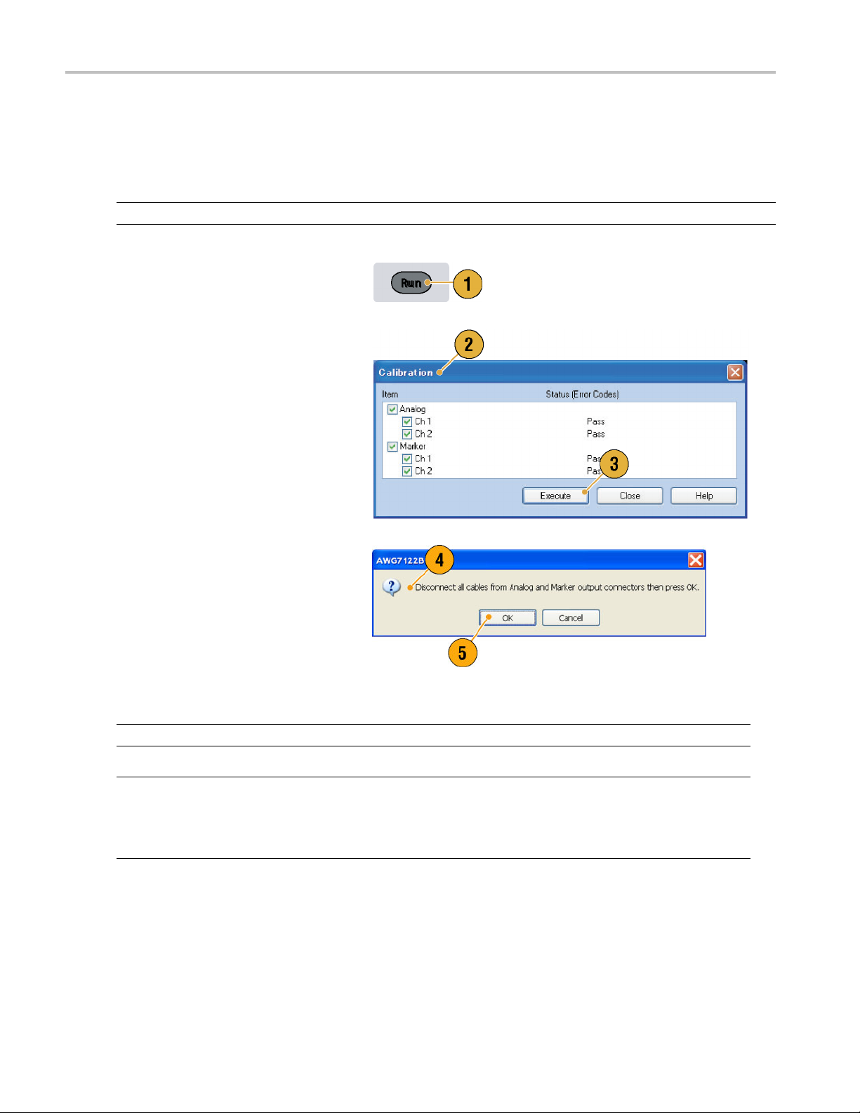
1. Confirm that there is no output signal by
verifying that the front-panel Run button
indicator is off.
2. To perform the calibration suite, select
System > Calibration from the menu
bar.
The Calibration dialog box appears.
3. Select Execute.
4. A pop-u
5. Remove the cables and then select OK.
NOTE. Self calibration is not valid until the instrument reaches a valid temperature. (See page 2, Operating Requirements.)
NOTE. If your instrument is an AWG7000 series, perform self ca libration once a month to maintain the analog and marker
put level accuracy. Failure to do so can prevent the instrument from meeting warranted performance levels for analog
out
and marker output.
If your instrument is an AWG5000 series, perform self calibration once a year to maintain the analog output level accuracy.
p message asks you to remove
all the cables from output connectors.
Wait until the calibration completes.
calibration items, the Status
For all
control should indicate Pass. If it does
not, contact your local Tektronix service
nnel.
perso
8 AWG5000 and AWG7000 Series Quick Start User Manual
Preventing Instrument Damage
Overheat Protection
The internal instrument temperature is monitored and the instrument is protected against overheating damage by the
following actions:
A warning message will appear if the internal temperature reaches the first threshold level.
The instrument will shut down if its temperature reaches the second threshold level.
If the warning message appears or the instrument shuts down, check for the following conditions. (See page 2, Operating
Requiremen
ts.)
Installing Your
Instrument
The ambient
The requir
The instru
temperature requirement is not being met.
ed cooling clearance is not being met.
ment fan is not working properly.
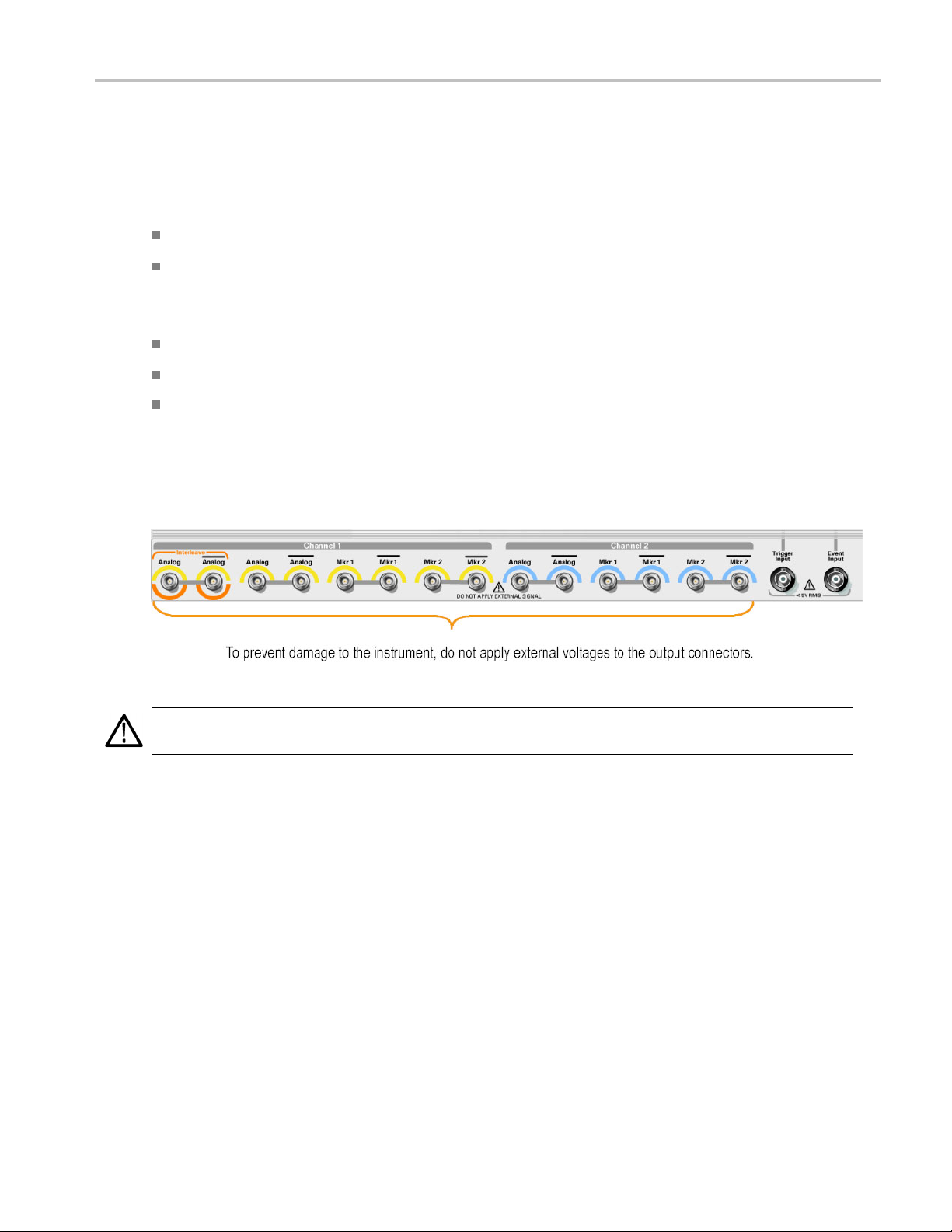
Output Connectors
The arbitrary waveform generator has both output and input connectors on the front panel. Do not apply external voltage
to the output connectors.
CAUTION. Always turn off the signal outputs when you connect or disconnect cables to/from the signal outputs connectors.
If you connect a DUT while the instrument signal outputs are in the On state, it may cause damage to the instrument or DUT.
AWG5000 and AWG7000 Series Quick Start U ser Manual 9
Installing Your
Instrument
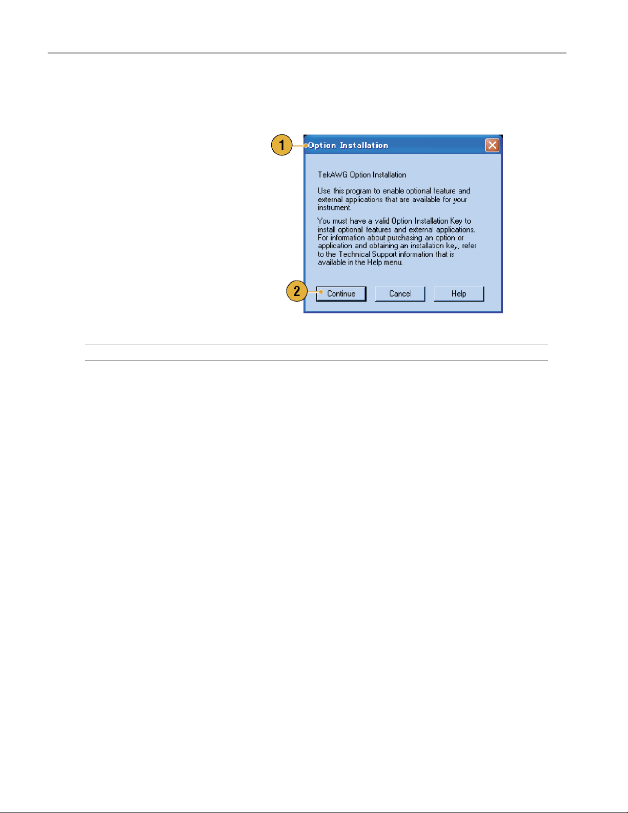
Option Installation
Use the Option Installation dialog box to enable the upgrades that you purchased from Tektronix for your instrument. For the
most current list of upgrades, go to www.tektronix.com or contact your local Tektronix representative.
1. Select System > Option Installation to
open the Option Installation dialog box.
2. Click Continue to open the second
dialog box.
Enter the Option Installation Key
provided by Tektronix, and follow the
on-screen instructions to install the
option.
NOTE. After entering the option key, you must restart the instrument application to activate the option.
10 AWG5000 and AWG7000 Series Quick Start User Manual
Creating Operat
ing System Restore Discs
Creating Oper
The instrument does not ship with an operating system restore disc. Use the following procedure to create a set of discs that
enable you to restore the operating system if the need arises.
CAUTION. Restoring the operating system reformats the hard disk d rive. User data, including the ISO images, will be lost
(the Acronis Recovery partition and the related data are not destroyed). To avoid complications, create the operating system
restore discs before attempting to restore the operating system.
NOTE. This procedure creates a set of restore discs for the Microsoft Windows operating system. After restoring the
operating s ystem, reinstall the instrument application software. Go to the Tektronix Web site (www.tektronix.com/software) to
download the product software, and follow the instructions to reinstall the instrument application software.
ating System Restore Discs
Creating Restore Discs
Prerequi
sites.
A separa
USB flash
DVD burner.
Blank DVD-R (NOT DVD-R/W) discs (about 2; the exact number depends on the number of backup files).
You will need:
te PC with a DVD±R/W drive and DVD burning software.
drive (8 GB or larger) or a local area network to transfer ISO image files from the instrument to the PC with
To create a set of restore discs:
1. On the instrument, navigate to C:\backup.
2. Using the USB flash drive (or through your LAN), transfer each of the files labeled restoreN.iso to the PC w ith the
DVD burner.
3. Using the DVD burning software, burn each of the backup ISO image files (restore1.iso to restoreN.iso) to a disc. Label
f the discs with the backup file name, instrument name, instrument serial number, and date.
each o
4. After
5. Store the backup discs as defined by your company policy.
NOT
toring the Instrument Operating System
Res
You can restore the instrument operating system from either a file on the instrument hard disk drive, or from the set of
instrument restore discs. (See page 11, Creating R estore Discs.)
CAUTION. Restoring the operating system reformats the hard disk drive. User data, including the ISO images w ill be lost
(the Acronis Recovery partition and the related data are not destroyed).
you have burned the OS restore discs, also place copies of the disk image files (*.iso) in a network location, on a
separate hard disk, or on optical media for backup purposes. (If you ever restore the instrument OS, the ISO images
on the instrument hard disk will be erased.)
E. You can use restore discs only on the instrument with which they were created.
AWG5000 and AWG7000 Series Quick Start U ser Manual 11

Creating Operat
Restoring the Operating System from the Restore Discs
ing System Restore Discs
NOTE. This pro
NOTE. You can use restore discs only on the in strument with which they were created.
1. Insert restore disc 1 in the instrument DVD drive.
2. Restart the instrument. The restore software opens automatically if the DV D drive is the first bootable device. If the
DVD drive is
from the discs.
3. Click Restore.
4. In the Confirmation dialog box, c lick Yes to restore the operating system, or No to exit the restore process.
5. When prompted, remove the current restore disc and insert the requested disc. Continue until the restore process
is complete.
NOTE. The
long as the disc drive light continues to blink.
NOTE. At the beginning and end of the recovery session, the recovery application will request you to repeatedly provide the
d last discs in the set. This is normal behavior for the recovery application.
first an
cedure requires that the DVD drive is set as the first boot device (this is the default setting).
not the first bootable device, you must enable it as the first bootable device before performing a restore
progress bar might not move during parts of the restore process. However, the restore process is working as
6. When the restore process is completed, remove the last restore disc and restart the instrument.
7. Install the AWG application software. If you have not already done so, go to the Tektronix Web site to download the
software (www.tektronix.com/software) and follow the instructions to install the software for your instrument.
oring the Operating System from the Instrument Hard Disk
Rest
The instrument contains an operating system restore file on a separate partition of the hard drive.
1. Restart the instrument. During the boot-up process you will see the following message at the top of the screen:
Starting Acronis Loader… press F5 for Acronis Startup Recovery Manager
2. Repeatedly press the F5 key until the Acronis True Image Tool opens. There is a five-second time period from when the
message appears until the instrument proceeds with the normal instrument startup. If the instrument does not open the
Acronis application, power off the instrument, then power on the instrument and try again.
3. Click Restore.
4. In the Confirmation dialog box, click Yes to restore the instrument operating system, or No to exit the restore process.
The restore process takes approximately 10 minutes; the actual time depends on the instrument configuration.
5. Install the AWG application software. If you have not already done so, go to the Tektronix Web site to download the
software (www.tektronix.com/software) and follow the instructions to install the software for your instrument.
12 AWG5000 and AWG7000 Series Quick Start User Manual
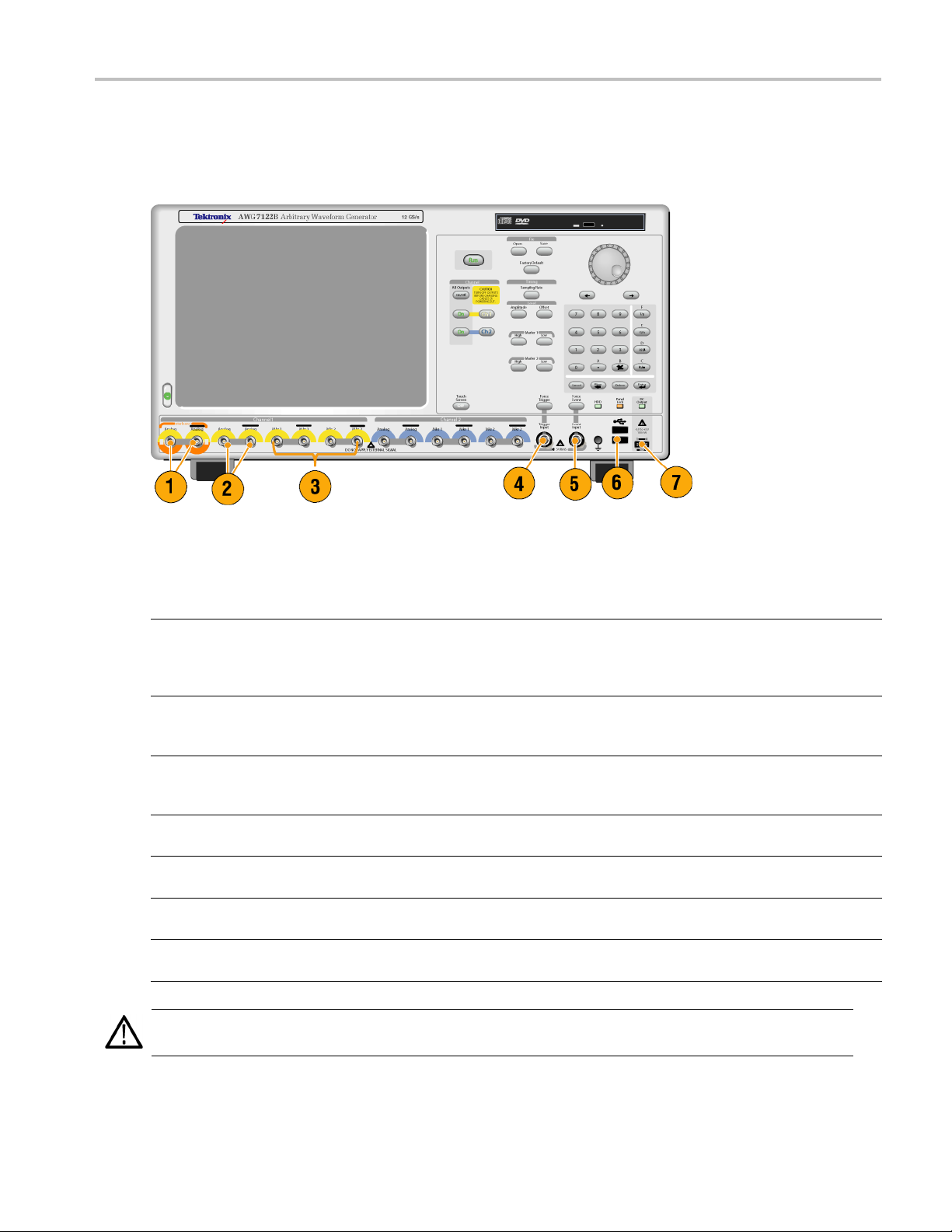
Front Panel
The following figure shows the front panel of an AWG7000 series instrument; AWG5000 series instruments are similar.
Front Panel
Front Panel Connectors
Connector Description
1. Interleave Output The interleave connectors supply analog signals with 12 GS/s through
24 GS/s range (AWG7000C series Option 06 and AWG7122B Option 06
only). The AWG7082C Option 06 range is from 8 GS/s to 16 GS/s.
Connector type: SMA
2. Analog Output
3. Marker Output
4. Trigger Input External trigger signal is applied to this connector.
5. Event Input Event signal is applied to this connector.
6. USB Two USB connectors are present on the front panel.
7. DC Output This connector supplies four channel DC voltage.
CAUTION. Always turn off the signal outputs when you connect or disconnect cables to/from the signal outputs connectors.
If you connect a DUT while the instrument signal outputs are in the On state, it might cause damage to the instrument or DUT.
These connectors supply analog signals.
Connector type: SMA (AWG7000 series)
Connector type: BNC (AWG5000 series)
These connectors supply marker signals.
Connector type: SMA (AWG7000 series)
Connector type: BNC (AWG5000 series)
Connector type: BNC
Connector type: BNC
Connect a USB device.
Connector type: 2.54 mm 2 x 4 pin header (female)
AWG5000 and AWG7000 Series Quick Start U ser Manual 13
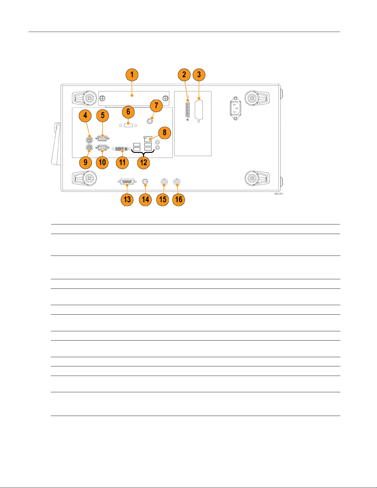
Rear Panel (AWG7
000C Series)
Rear Panel (AW
NOTE. AWG7000B series have a similar connectors in different locations.
G7000C Series)
Connector Description
1. Removable HDD
2. Tek L i nk
3. GPIB Use the GPIB connector to connect the instrument to a GPIB controller
4. PS-2 Mouse connector Use the PS-2 connector to connect a mouse to the instrument.
5. COM2 Use the COM2 serial port to c onnect to other devices through the serial
6. eSATA port Use the eSATA port to connect external SATA devices to the instrument.
7. Synchronization Clock Out port Use the Synchronization Clock Out port to provide a synchronization signal
8. LAN Use the RJ-45 connector to connect the instrument to a network.
9. PS-2 Keyboard connector Use the PS-2 connector to connect a PS-2 keyboard to the instrument.
10. COM1 Use the COM1 serial port to connect to other devices through the serial
11. Video
Removable hard disk drive to secure data. If you remove the HDD, user
information such as setup files or waveform data does not remain within
the instrument.
Use the TekLink connector for data import.
for GPIB operation.
port.
to other external devices. Terminate this connector when not in use.
port.
Use the DVI-I Video port to connect a monitor for extended desktop
operation. To connect a VG A monitor to the DVI-I connector, use a
VGA-to-DVI adapter.
14 AWG5000 and AWG7000 Series Quick Start User Manual

Connector Description
12. USB Use the USB con
USB device to the instrument.
13. Dynamic Jump I
14. External Clock Input Input connector for oscillator input
15. Reference C
16. 10 MHz Reference Output Output connector for 10 MHz reference clock signal
n connector
lock Input
Use the 15-pin DSUB connector to allow fast switching during table jump
and subsequence operations. (AWG7000C series)
Connector T
Input conne
Connector Type: BNC
Connector Type: BNC
nectors to connect a USB mouse, keyboard, or other
ype: SMA
ctor for external reference c lock
Dynamic Jump In Connector (AWG7000C Series)
AWG7000C instruments have a Dynamic Jump In Connector on the rear panel that accepts TTL-level signals from 0.0 V to
+5.0 V (DC + Peak AC). Use the 15-pin type D connector to connect an Jump In signal to the instrument. The instrument
accepts a strobe signal and eight Jump In signals. The following illustration and table show the pin connections for
the connector.
Rear Panel (AWG7
000C Series)
Pin number Signal Direction
1
2 Jump bit 0 Input
3 Jump bit 1 Input
4 Jump bit 2 Input
5
6
7
8
9
10 Jump bit 4 Input
11 Jump bit 5 Input
12 Jump bit 6 Input
13 Jump bit 7 Input
14
15
GND
Jump bit 3 Input
GND
Strobe
GND
GND
GND
GND
Input
AWG5000 and AWG7000 Series Quick Start U ser Manual 15

Rear Panel (AWG5
000C Series)
Rear Panel (AW
G5000C Series)
NOTE. AWG5000B series have a similar connectors in different locations.
Connector Description
1. Remova
2. Tek L i nk
3. GPIB Use t
4. PS-2 Mouse connector Use the PS-2 connector to connect a mouse to the instrument.
5. COM2 Use the COM2 serial port to connect to other devices through the serial port.
6. eSATA port Use the eSATA port to connect external SATA devices to the instrument.
7. LA
8.P
9.C
10. Video
11. USB Use the USB connectors to connect a USB mouse, keyboard, or other USB device
12. Digital Data Out Use these connectors to output digital data. To enable digital data output, Option
ble HDD
N
S-2 Keyboard connector
OM1
Removable hard disk drive to secure data. If you remove the HDD, user information
such as setup files or waveform data does not remain within the instrument.
Use the TekLink connector for data import or connecting the Option 09 TTL Event to
nk LVDS Connector Adapter box.
TekLi
he GPIB connector to connect the instrument to a G PIB controller for GPIB
operation.
e the RJ-45 connector to connect the instrument to a network.
Us
se the PS-2 connector to connect a PS-2 keyboard to the instrument.
U
se the COM1 serial port to connect to other devices through the serial port.
U
Use the DVI-I Video port to connect a monitor for extended desktop operation. To
connect a VGA monitor to the DVI-I connector, use a VGA-to-DVI adapter.
to the instrument.
03 must be installed in the AWG5002C, AWG5012C, AWG5002B, or AWG5012B.
Connector Type: S MB
16 AWG5000 and AWG7000 Series Quick Start User Manual

Connector Description
13. Add Input
14. External Clock Input Input connector for oscillator input
15. Oscillator Output Output connector for internal oscillator
16. Reference C
17. 10 MHz Reference Output Output connector for 10 MHz reference clock signal
lock Input
Adds an extern
Connector Type: BNC
Connector Type: BNC
Connector T
Input conne
Connector Type: BNC
Connector Type: BNC
al signal to the output signal of the arbitrary waveform generator.
ype: BNC
ctor for external reference clock
Rear Panel (AWG5
000C Series)
AWG5000 and AWG7000 Series Quick Start U ser Manual 17

Getting Acquain
ted with Your Instrument
Getting Acqua
Control Panel
inted with Your Instrument
Buttons/Keys Description
1. Run
2. All Outputs On/Off If one or more Outputs are on, they will all be turned off when you push the
3. Channel Output On These buttons are used to enable/disable the channel output. If the output
4. Channel Select These buttons are used to select a channel that you want to interact with. If
5. File – O pen/Save When the Open or Save button is pushed, the corresponding dialog box is
6. Factory Default When this button is pushed, the specified default setups are recalled. (See
7. Sampling Rate When you push this button, the sampling rate parameter in the Settings
The Run button is used to start and stop the signal generation. If the signal
is being generated, the LED indicator lights up.
To output the signal through the output connectors, you must push the
front-panel All Outputs On/O ff button or the Channel Output On button.
All Outputs On/Off button. If all Outputs are off, they will all be turned on
when you push the All Outputs On/Off button.
is in the On state, the LED is turned on.
a channel select button on the front panel is pushed, the selected channel
page in the Settings Window will be activated.
displayed. You can load or save a setup (*.AWG) file using this dialog box.
page 43, Default Setup.)
window is selected. Sampling Rate is common to each channel.
18 AWG5000 and AWG7000 Series Quick Start User Manual

Getting Acquain
Buttons/Keys Description
8. Level – Amplit
9. Marker 1 and Marker 2 – High/Low When you push one of these buttons, the Marker High or Marker Low
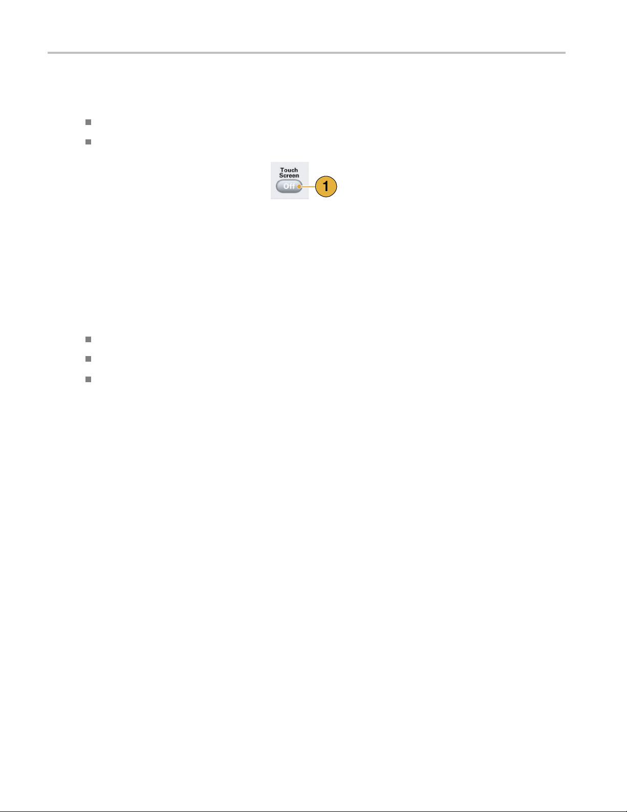
10. Touch Screen Off When the Touch Screen is On state, you can use your finger or stylus to
11. Force Trigger When you push this button, the instrument generates an internal trigger
12. Force Event When you push this button, the instrument generates an internal event
13. General P
14. Digit Se
15. Numeric Keypad
ude/Offset
urpose Knob
lect Arrow Keys
When you push t
corresponding channel in the Settings window is selected.
Amplitude and offset can be set independently for each channel.
parameter of
Marker High and Marker Low can be set independently for each channel.
control the screen interface. The LED is lit while the Touch Screen interface
is disabled
signal.
signal.
The knob i
a pop-up menu, pull-down menu, or dialog box. Turn the knob clockwise
to increase the value, and turn the knob counterclockwise to decrease
e.
the valu
t select arrow keys are used to move the under bar (cursor) to a
The digi
field that contains an editable number. After you specify the digit, you can
change the number with the knob.
Units prefix buttons (T/p, G/n, M/μ, and k/m) are used to complete an input
he numeric keypad. You can determine the units by pushing one of
with t
these prefix buttons without pressing the Enter key.
If you push the units prefix buttons for frequency, the units are interpreted
era-), G (giga-), M (mega-), or k (kiro-). If you push the buttons for
as T (t
time, the units are interpreted as p (pico-), n (nano-), μ (micro-), or m (milli-).
hese buttons, the amplitude or offset parameter of the
the corresponding channel in the Settings window is selected.
.
s used to increase or decrease a set value or select an item from
tedwithYourInstrument
ION. Do not connect a DUT (Device Under Test) to the front-panel signal output connectors when the instrument
CAUT
signal outputs are on.
Do not power on or off the DUT when the arbitrary waveform generator signal outputs are on.
Locking and Unlocking the Front Panel Controls
The front panel may be locked by a remote user while the arbitrary waveform generator is being remotely controlled via GPIB
or Ethernet. When the front panel is locked, all keys and buttons are disabled except the power switch. You cannot use your
mouse or keyboard. However, the Windows operations are available even if the instrument front panel is locked.
To unlock the front-panel controls, use a remote command or push the front-panel Cancel button twice. If you exit the
application, the lock state is cleared. When you restart the application, the front-panel controls are unlocked.
AWG5000 and AWG7000 Series Quick Start U ser Manual 19
Getting Acquain
ted with Your Instrument
Touch Screen Interface
The arbitrary waveform generator offers two methods of making menu selections:
Front-panel controls, keyboard, and mouse (keyboard and mouse are standard accessories)
Front-panel controls and touch screen interface
1. You can enable or disable the touch
screen interface by pushing the
front-panel Touch Screen button.
When the touch screen is in the Off state,
the LED is lighted. You can still access
the on-screen menus with a mouse or
keyboard.
Quick Tip
Click the Calibrate Touchscreen icon on the desktop to adjust the touch screen. (See page 20, Elo Touchscreen Application.)
You may ne
ed to adjust the touch screen under the following situations:
The opera
The hard
The touc
ting system is restored
disk drive is exchanged
h screen is not responding correctly
Elo Touchscreen Application
If you experience problems with the touch screen, you must verify the touch screen selections in the Elo Touchscreen
application. If the settings are different, change the settings as recommended:
1. From the Windows Start menu, select Control Panel.
2. Double-click the Elo Touchscreen icon in the Control Panel.
3. Select the Properties 1 tab and then click the Advanced button.
4. Under the Edge acceleration tool, verify that Enable Edge Acceleration is selected.
5. Click OK.
6. Select the Mode tab.
7. Under the C alibration mode, verify that Enhanced is selec ted.
8. Click OK and then close the Control Panel.
9. Click the Calibrate Touchscreen icon on the desktop to recalibrate the touch screen.
20 AWG5000 and AWG7000 Series Quick Start User Manual

Screen Interface
Getting Acquain
tedwithYourInstrument
Screen element Description
1. Menu bar
2. Status bar The status bar shows information about the instrument, such as sampling
3. Waveform List window User-defined waveforms and predefined waveforms are listed in this
4. Sequence window This window mainly provides information on output sequence.
5. Waveform window This window displays the waveform that you selected in the Settings
6. Settings window This window is provided for quick access to the parameter settings.
7. Window tag
8. Remote command bar Displays a remote command corresponding to current instrument operation.
The menu bar provides access to all of the instrument functions.
rate, run mode status, or output status.
window.
window or in the Sequence window.
Click these tags to toggle d isplay of corresponding windows on or off.
AWG5000 and AWG7000 Series Quick Start U ser Manual 21
Getting Acquain
ted with Your Instrument
Basic Steps for Using the Arbitrary Waveform Generator
After you have powered on the instrument, use the menu bar in the application or use control windows to create and edit
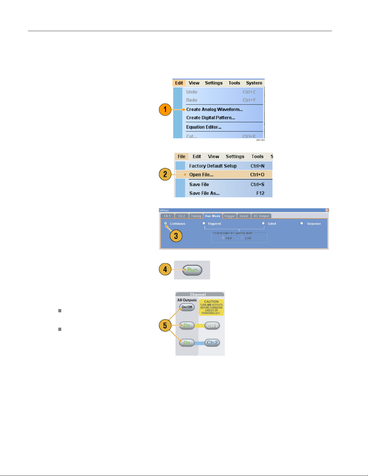
waveforms. (See page 24, Accessing Menus and Control Windows.) Complete the following steps to output a waveform:
1. To create a new analog waveform, select
Edit > Create Analog Waveform.The
created waveform is displayed in the
Waveform List window.
2. To use an existing waveform, select File
> Open File to open a setup file, and
then sele
List window.
ct a waveform in the Waveform
3. Confirm the Run mode. Check that the
desired run mode is selected on the Run
Mode tab
4. To generate a signal, push the front-panel
Run bu
Status Bar.
5. Use one of the following methods to set
the channel output On:
of the Settings window.
tton or the Run button on the
Front-panel Channel Output On
on or All Outputs O n/Off button
butt
ut On button of the Ch page of
Outp
Settings window
22 AWG5000 and AWG7000 Series Quick Start User Manual

Run Mode
The arbitrary waveform generator supports the following four types of Run mode:
Continuous. A continuous waveform is output.
Triggered. A waveform is output once when the instrument receives a trigger signal. The instrument will wait for the next
trigger signal after outputting the waveform.
Gated. A waveform is output only when a gate signal is asserted. A continuous waveform is output while the gate
signal stays asserted.
Sequence. Multiple waveforms can be output in the order specified in the sequence.
You can select a run mode using the Run Mode page of Settings window.
1. Select a Run mode.
2. In the Triggered or Gated mode, you
can select the output value while the
instrument is in the waiting-for-trigger
state.
Getting Acquain
tedwithYourInstrument
First – Sets the output level to the
first value of the waveform
Last – Sets the output level to the last
value of the waveform
Trigger Control
Trigger controls waveform output when the Run mode is Triggered, G
window to set Trigger parameters.
1. You can select Trigger Source (Internal
or External). The default is External.
2. If External is selected, Trigger Level,
Trigger Slope, and Trigger Impedance
canbeset.
Level – Sets external trigger level.
Slope – Determines whether the
instrument finds trigger point on the
rising edge or the falling edge of the
signal.
ated or Sequence. Use the Trigger page of Settings
Impedance – Specifies external
trigger impedance (1 kΩ or 50 Ω).
3. If Internal is selected, internal trigger
Interval can be set.
AWG5000 and AWG7000 Series Quick Start U ser Manual 23

Getting Acquain
ted with Your Instrument
Quick Tips
Trigger parameters control the signal outputs of the instrument. Trigger parameters cannot be set if Continuous is
selected in the Run Mode.
You can also control the trigger by pushing the front-panel Force Trigger button in addition to specifying a signal as
the trigger source.
Accessing Menus and Control Windows
You can access menu commands and control windows using the following techniques:
1. Click Settings from the menu bar, and
then selec
The selected item in the Settings window
will become active.
t a command.
2. For a shortcut to settings menus, y ou
can use the Settings window.
Clicking a tab, such as Ch 1 or Timing,
on the Settings window opens the
corresponding page that you can use to
select the instrument settings.
3. From the front panel, you can quickly
access the parameters for sampling rate,
amplitude level, offset level, and marker
level.
If you push one of these buttons, the
corresponding parameter in the Settings
window will be selected.
24 AWG5000 and AWG7000 Series Quick Start User Manual

Getting Acquain
tedwithYourInstrument
4. You can right-c
to associated menu commands.
For example, right-click the Waveform
List window to
commands.
lick to gain quick access
display the related menu
Changing Control Settings
As you configure the instrument, you might need to set a numerical parameter such as an amplitude level or offset. To set
these parameters in a screen window, touch or click the parameter to select it. Once the parameter is selected, the general
purpose k
You can use the general purpose knob to change parameters, although the following methods are generally available.
nob is assigned to the parameter.
Some parameters supply a pop-up
keypad or keyboard that you can use to
enter a n
Touch or click the keypad (or keyboard)
icon to display the keypad (or keyboard).
Touch or click the parameter to select it.
Move the underbar to a digit, and then
use the digit select arrow keys to change
the value of the digit.
ew value.
AWG5000 and AWG7000 Series Quick Start U ser Manual 25

Getting Acquain
ted with Your Instrument
Display/Hide Control Windows
The arbitrary waveform generator displays four control windows by default. You can quickly hide or display each window
using the window tag.
1. By default, four windows are displayed if
the Run mode is Sequence.
2. Click the Settings tag.
3. The Settings window is hidden.
26 AWG5000 and AWG7000 Series Quick Start User Manual

Status Bar
The Status Bar has two functions. It displays the status of the instrument, such as Sampling Rate, Run State, and Run Mode.
It also has action buttons, such as Force Trigger, Force Event, All Outputs On/Off, and Run.
1. Sampling Rate Sampling rate setting is displayed.
2. Run Status Instrument status (Running or Stopped) is displayed.
3. Run Mode Run Mode is displayed.
4. Force Tri
5. Force Eve
6. All Outputs On/Off button Same function as the front-panel All Outputs On/Off button.
7. Run but
gger button
nt button
ton
Getting Acquain
Same function as the front-panel Force Trigger button.
Same function as the front-panel Force Event button.
Same function as the front-panel Run button.
tedwithYourInstrument
AWG5000 and AWG7000 Series Quick Start U ser Manual 27

Getting Acquain
ted with Your Instrument
Setting the User Preferences
Select System
Preferences dialog box.
1. Startup – Select a power-on setting.
(See page 43, Changing Settings at
Power-On.)
2. LCD Brightne
brightness.
3. Fit to Window Based On – Select the
vertical scale setting when you use the
Zoom Fit fun
H/W Output
Waveform Data – Vertical scale is
4. Hold – Sel
when the effective waveform length is
modified.
Sampling Rate
Repetition Rate
> Preferences to open the
ss – Set the LCD
ction.
Range – Vertical scale
is set based on the instrument
hardware limitation.
set based
on the waveform data.
ect which parameter is held
5. Remote Command Log – You can record
uence of GPIB commands you
the seq
used with your instrument.
28 AWG5000 and AWG7000 Series Quick Start User Manual

Changing the Windows Display Style
You can configure the appearance of Waveform and Sequence windows for your arbitrary waveform generator.
Waveform Window
1. Select View > Display P roperties to
display the Display Properties dialog box.
Click the Waveform Window tab.
2. You can select the Waveform window
display format (Graphic or Table ).
3. This example shows Graphic display.
The view is fixed to Analog. You can
select on and off for Overlay and Grid.
4. When Overlay is specified, analog data
from multiple channels can be displayed
overlaid.
5. Select waveform thickness.
Getting Acquain
tedwithYourInstrument
6. You c an select vertical units. Select
Voltage or Normalized in the View data
as box.
7. You can select horizontal units. Select
Points or Time in the Scale box.
8. Click Table to set the Waveform window
to Table display.
9. You need to select Analog or Digital
when Table is specified.
10. When Digital is selected, you can select
Binary or Hex.
11. You can select the vertical and horizontal
units. If Digital is selected in the Table
display, vertical units selection (Voltage
or Normalized) is disabled.
12. You can select displayed items for each
channel in the Waveform window.
AWG5000 and AWG7000 Series Quick Start U ser Manual 29

Getting Acquain
Sequence Window
1. Select View > Display Properties to
display the Display Properties dialog box.
Click the Sequence Window tab.
2. You can select the display format
(Graphic or Table).
3. When Graphic is selected, you can select
either Thumbnail or Waveform Name.
ted with Your Instrument
Quick Tips
(AWG7000 series only) When the DAC resolution of a channel is set to 10 bits, the marker data of the channel cannot
be displayed.
You can also access the Display Properties dialog box by right-clicking on the Waveform or Sequence window.
Run State Control and Output On/Off
Do the following steps to control the start and stop of signal generation for th
1. Use the front-panel Run button to start
and stop signal generation.
Switching signal generation on or off is
called Run State control.
If a signal is being generated, the LED
indicator lights up.
2. To output the signal through the output
connectors, push the front-panel All
Outputs On/Off button or the Channel
Output On button.
e arbitrary waveform generator.
30 AWG5000 and AWG7000 Series Quick Start User Manual

3. Alternatively, you can use the Ch n
(Channel) tab on the Settings window to
enable the sig
nal output.
Getting Acquain
tedwithYourInstrument
AWG5000 and AWG7000 Series Quick Start U ser Manual 31

Getting Acquain
ted with Your Instrument
Setting Output Signals
Analog and Marker Output
You can set the parameters for analog and marker output signals using the front panel buttons or the Channel page
of Settings w
1. Use the front-panel Level buttons to
set the Amplitude, Offset, and Marker
High/Low fo
2. Similarly, you can set parameters for
Amplitude, Offset, and Filter using the
Chnpageo
indow.
r each channel.
f Settings window.
3. You can s
low and delay.
4. (AWG7000 series) When 10 bits DAC
Resolution is selected, Marker Outputs
will be d
5. Select
6. (AWG50
external signal to each channel analog
output.
7. When the instrument is in the
non-sequence mode, you can select the
outp
Waveform field. Click the waveform list
icon to display the Waveform List dialog
box
8. You
analog output signal when the instrument
is in the non-sequence mode.
et parameters for marker high,
isabled.
Direct Output On and Off.
00 series) You can add an
ut waveform data using the Output
.
can set phase shift or delay for each
32 AWG5000 and AWG7000 Series Quick Start User Manual
Getting Acquain
tedwithYourInstrument
Quick Tips
Each channel has independent output on and off control. When the output status of Ch n is set to On, both analog output
and marker output are enabled.
When Direct Output is set to On, filter and offset settings become inactive. The analog bandwidth setting range will
change.
(AWG7000 series) The Option 02 (Extended analog output bandwidth) and Option 06 (Interleave and wide bandwidth
direct output) models do not have the control settings for Filter, Offset, and Direct Output.
(AWG5000 series) You can use Add Input when Direct Output is set to off. If Direct Output is selected, Add Input
is disabled.
The Waveform Rotation can be set independently for each channel.
Analog Phase – Can be set by degree (°).
Analog Delay – Can be set by time or points.
The Waveform Rotation setting does not affect the Waveform window display.
DC Output Page
1. The arbitrary waveform generator has
four lines of DC output.
The level of each output can be set
independently.
2. The output state (On or Off) of the
DC output is common to all DC output
channels.
AWG5000 and AWG7000 Series Quick Start U ser Manual 33

Getting Acquain
Timing Control
You can set parameters for sampling rate or clock using the Timing page of Settings window.
ted with Your Instrument
1. Sets Sampling
2. You can set Rep
Run mode is not set to Sequence.
3. You can select Clock Source (Internal
or External).
If External is selected, the clock
signal from
is used.
If Internal is selected, the clock signal
is generated internally.
4. Divider Rate can be set when the Clock
Source is s
5. You c a n se
(Internal or External).
Reference Source is selectable only
when the
6. You c a n s
Type (Variable or Fixed).
This parameter is selectable only w hen
ck Source is set to Internal and
the Clo
the Reference Source is set to External.
Rate.
etition Rate when the
External Oscillator Input
et to External.
lect the R eference Source
Clock Source is set to Internal.
elect the External Reference
Quick Tips
The Sampling Rate can be set w hen the internal clock source is selected and one of the following conditions is met:
Internal is selected as the reference source.
External is selected as the reference source and Fixed is selected as the external reference type.
The arbitrary waveform generator accepts a 10 MHz, 20 MHz, or 100 MHz frequency signal as a Fixed external
reference source.
You can set the Multiplier Rate when the Clock Source is set to Internal, the Reference Source is set to External,and
the External Reference Type is set to Variable.
34 AWG5000 and AWG7000 Series Quick Start User Manual

Getting Acquain
tedwithYourInstrument
Channel Coupling
You can change the parameter values for multiple channels at a time. This function is called Channel Coupling.
1. Select Settin
Coupling dialog box.
You can also open this dialog box
from the popright-clicking on the Channel page of the
Settings window.
2. Select a coupling m ethod.
Ch1->Ch2andCh3->Ch4means
that Ch 1 and Ch 2, and Ch 3 and Ch 4
are coupled, respectively.
3. Select Ch1->Ch2,Ch3,Ch4to
couple the Ch 1 parameters with Ch 2,
Ch 3, and Ch 4 parameters.
gs > Coupling to open the
up menu displayed by
Quick Tips
Ch1->Ch2,Ch3,Ch4means that Ch 1 parameters are coupled with Ch 2, Ch 3 and Ch 4 parameters. With the
Channel Coupling in the On state, the Ch 1 parameters are applied to the instrument hardware settings of the other
three channels. You cannot select parameters for channel coupling in the Channel page of the Settings window. The
disabled parameters are grayed out.
The following parameters are excluded from channel coupling:
Channel skew
Output waveform
Sequence waveform
External signal add function
Waveform rotation
Marker delay
Parameters that are not related to the output signal, such as marker display on/off
AWG5000 and AWG7000 Series Quick Start U ser Manual 35

Getting Acquain
Channel Skew Adjustment
The channel skew adjusts the skew (delay) of each channel output.
Select System > Channel Skew to open the
Channel Skew dialog box.
1. You can adjust the skew for each channel
independently. This adjustment applies
to analog output and marker output.
2. Adjusting the skew value will update the
dialog box display.
NOTE. If your instrument is a single channel model, the channel skew function is not supported.
ted with Your Instrument
Interleave
The AWG7000C series Option 06 and AWG7122B Option 06 offer interleave capability. The instrument can interleave two
channels to attain higher sampling rates and longer waveform length.
1. To activate Interleave, select the Ch 1
page of Settings window, and then check
the Interleave check box.
2. When Interleave is set to On, the Ch 2
tab is grayed out. You cannot access the
Ch 2 parameters.
3. When Interleave is in the On state, you
can select Zeroing On/Off.
The bandwidth becomes wider but the
amplitude r ange is changed with Zeroing
On. The default is Zeroing Off.
36 AWG5000 and AWG7000 Series Quick Start User Manual

Getting Acquain
tedwithYourInstrument
Quick Tips
Interleaving is applied to analog output. When interleaving is on, marker data with even numbers will be output, such
as 0,0,2,2,4,4,6,6.
When output is on, changing the Interleave mode on and off will turn the output off.
The following table lists how interleaving extends the maximum sampling rate and waveform length:
Instrument type and
option Interleave Sampling rate Waveform length
AWG7122C, AWG7122B
(Option 01, Option 06)
AWG7082C
(Option 01, Option 06)
AWG7122C, AWG7122B
(Option 06)
AWG7082C
(Option 06)
AWG7122C, AWG7122B
(Option 01)
AWG7082C
(Option 01)
AWG7122C, AWG7122B
(Standard models)
AWG7082C
(Standard model)
On 12 GS/s to 24 GS/s
Off 10MS/sto12GS/s
On 8GS/sto12GS/s
Off 10MS/sto8GS/s
On 12 GS/s to 24 GS/s
Off 10MS/sto12GS/s
On 8GS/sto16GS/s
Off 10MS/sto8GS/s
Not available
Not available
Not available
Not available
10 MS/s to 12 GS/s
10 MS/s to 8 GS/s
10 MS/s to 12 GS/s
10 MS/s to 8 GS/s
2 to 129,600,000 points
1 to 64,800,000 points
2 to 129,600,000 points
1 to 64,800,000 points
2 to 64,800,000 points
1 to 32,400,000 points
2 to 64,800,000 points
1 to 32,400,000 points
1 to 64,800,000 points
1 to 64,800,000 points
1 to 32,400,000 points
1 to 32,400,000 points
AWG5000 and AWG7000 Series Quick Start U ser Manual 37

Getting Acquain
Interleave Adjustment
Interleaving is a function to attain twice the sampling rate of single channel by combining the Ch 1 and Ch 2 outputs. When the
interleaving is set to On, you can adjust the relative values for Phase and Amplitude between the channels.
1. In this example, Ch 1 amplitude is set to
0.75 Vp-p. Use the Settings window to
enter Ch 1 amp
2. Select System > Interleave Adjustment
to open the Interleave Adjustment dialog
box.
Enter 0.100 Vp-p in this example as an
adjustment value of relative amplitude.
3. Both Ch 1 and Ch 2 amplitude values
are adjusted internally. See the Quick
Tip below for calculation formula.
ted with Your Instrument
litude value.
4. The phase adjustment will be done by
fixing Ch 1 and changing Ch 2. The
adjustment units are degrees. The
setting range is as follows:
-180.0 to +180.0 degrees
Quick Tip
Ch 1 and Ch 2 will be adjusted internally in the amplitude adjustment. The internal amplitude values for each
Both
channel will be calculated as follows:
Internal Ch 1 Amplitude = Ch 1 Amplitude Value – Adjustment Value
Internal Ch 2 Amplitude = Ch 1 Amplitude Value + Adjustment Value
NOTE. You can set the amplitude adjustment value within the range of Ch 1 amplitude setting. The adjustment value may
lipped to maximum or minimum value depending on the Ch 1 amplitude setting. The c lipped value will be applied to
be c
the instrument hardware.
38 AWG5000 and AWG7000 Series Quick Start User Manual

Digital Output (Option 03)
Option 03 supports digital data output on AWG5002C, AWG5012C, AWG5002B, and AWG5012B instruments.
1. The SMB connectors for 14 bit digital
data output are present for Ch 1 and
Ch 2 on the rear panel.
2. You can set the output parameters as
follows:
Digital Amplitude/Offset
Digital High/Low
The digita
follows:
l output levels are fixed as
–1.0 V to +2.7 V, into 50 Ω
Getting Acquain
tedwithYourInstrument
0.01 V resolution
Quick Tip
Each channel has independent output on and off control. When the output status of Ch n is set to On, both analog
ut and digital output are enabled.
outp
AWG5000 and AWG7000 Series Quick Start U ser Manual 39

Saving and Recal
ling Setups
Saving and Rec
Use the File menu for basic file operations such as saving or recalling instrument setups or importing or exporting waveform
data. You can also use the File menu for standard Windows operations such as loading the most r ecent setup files.
File Menu
The following menu items are provided in the File menu. For a complete description of each menu command, refer to
the instrum
1. Recalls factory default setups. (See
2. Opens a dialog box to load an instrument
3. Saves (Ove
4. Saves an i
5. Use these commands to import
6. Exports waveform data to a file for use
ent online help system.
page 43, Default Setup.)
setup.
rwrites) an instrument setup.
nstrument setup assigning a
new setup file name.
waveform data.
er applications.
with oth
alling Setups
7. Alistof
8. The application closes.
9. The application closes and then the
Quick
setup files you accessed recently
is displayed here.
instrument shuts down.
Tip
You can also shut down the instrument by pushing the front-panel power button (On/Standby switch) while the application
is running. When the power button is pushed, a dialog box asks you whether to save current setups. If you select Yes,
the current setups are preserved and then the instrument will start the shutdown process.
40 AWG5000 and AWG7000 Series Quick Start User Manual
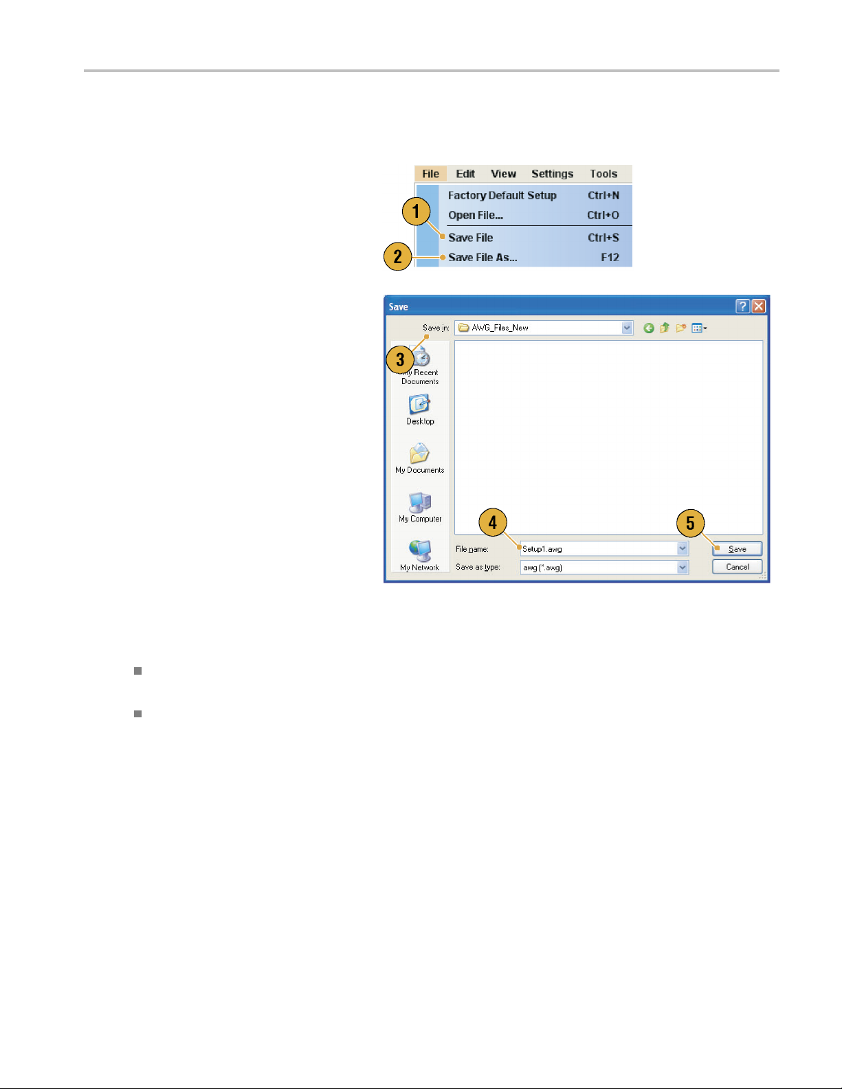
Saving an Instrument Setup
Use the following steps to save an instrument setup:
1. Select File > Save File to overwrite
the existing instrument setup with an
updated setup file.
2. To save the current setup to a new setup
file, select File > Save File As or push
the front-panel Save button.
3. Select a location where you want to save
the setup.
Saving and Recal
ling Setups
4. Type a file n
5. Click Save
ame or use the default name.
.
Quick Tips
If a setup file contains Integer format waveform(s), the file size is reduced. For more information about waveform
data format (Real or Integer), refer to the online help.
To change the waveform format in the Waveform, Waveform List, or Settings window, you can use the Waveform
erties dialog box. (See page 57, Confirming Waveform Properties.)
Prop
AWG5000 and AWG7000 Series Quick Start U ser Manual 41

Saving and Recal
ling Setups
Recalling an Instrument Setup
Yo u can recall an instrument setup from the File menu or from Windows Explorer.
1. Select File > Open File to open the
Open File dialog box.
2. Select a setup file.
3. Click Open.
Quick Tips
The arbitrary waveform generator uses a setup file that has an extension AWG. Only *.AWG files are displayed on the
Open File dialog box by default.
Once you recall a setup, the instrument retains the setup until you execute Save File or Save File As. If you s elect Save
File after changing the instrument parameters, the instrument setup file will be automatically overwritten.
Output status including DC Output becomes Off when a setup file is recalled.
NOTE. The AWG5000 series and AWG7000 series setup files are compatible each other. However, if the parameter
value(s) of an instrument setup file are out of range, a warning message is displayed. In this case, out of range parameter
values are set to the default values.
42 AWG5000 and AWG7000 Series Quick Start User Manual

Default Setup
Push the front-panel Factory Default button to recall the factory default settings.
1. To quickly return to the factory default
settings, push the front-panel Factory
Default button.
2. When the instrument setups are
modified, a confirmation dialog box
appears.
3. You can also recall the factory default
settings from the File menu.
Saving and Recal
ling Setups
Changing Settings at Power-On
You can select the instrument settings that are restored when you power on the instrument.
Select System > Preferences to display the
Preferences dialog box. You can select the
power-on setups from the following:
1. Factory Default – The factory default
settings are always restored when the
instrument is powered on.
2. Last Used File – Restores the setups
that were saved or recalled last time.
3. User Default File – A specified setup file
is always restored when the instrument
is powered on.
4. Click the icon to display a dialog box to
select the setup file.
This icon is enabled when User Default
File is selected.
AWG5000 and AWG7000 Series Quick Start U ser Manual 43

Saving and Recal
ling Setups
Importing Waveform Data
Data import functions allow you to use waveform data created outside the arbitrary waveform generator. You can import data
to create a new waveform or to replace existing waveform data.
The arbitrary waveform generator supports the following file formats:
*.AWG file created by Tektronix AWG5000 series or AWG7000 series
The following file formats created by Tektronix arbitrary waveform generators such as AWG400/500/600/700 series:
*.pat
*.seq
*.wfm
*.TFW file created by Tektronix AFG3000 series arbitrary/function generators
*.DTG file created by Te ktronix DTG5000 series data timing generators
*.WFM or *.ISF fi le created by Tektronix TDS/DPO series oscilloscopes
Text file (*.TXT)
Refer to the online help system for more information about file import.
1. Select File > Import from File to display
the Import from File dialog box.
2. Select the file format that you want to
import.
3. Click OK. The File Import dialog box,
such as shown in step 4, is displayed.
44 AWG5000 and AWG7000 Series Quick Start User Manual

4. Select a file to import.
5. Select an import action in the Operation
frame.
Set to – Select the channel and index
number. The i
data w ill be assigned to the specified
position.
Insert before – The imported
waveform da
before the specified cell of the
sequence. When the run mode is
non-seque
disabled.
Create only – The imported
waveform will be added to the
Waveform L
mported waveform
ta will be inserted
nce, this parameter is
ist window.
Saving and Recal
ling Setups
Overwrit
waveform data is overwritten.
6. If the imported w aveform data contains
information on sampling rate, amplitude,
or offset, you can select whether you
load that information using the Change
H/W Setup.
For example, if you check the Sampling
Rate check box, the sampling rate will be
modified to reproduce the same signal
as the imported data.
7. Click Open.
When the import file format is *.AWG,
*.DTG, or *.TXT, a corresponding dialog
box is displayed.
When the import file format is other than
*.AWG, *.DTG, or *.TXT, the selected file
is imported and the waveform name(s)
are listed in the Waveform List window.
e – Specified existing
AWG5000 and AWG7000 Series Quick Start U ser Manual 45

Saving and Recal
8. If the file format is Tektronix
AWG5000 series or AWG7000 series,
the AWG File Im
displayed.
Select a waveform to import.
9. Click OK. The selected waveform is
imported.
You can select multiple waveforms.
10. If the file format is Tektronix
DTG5000 s
lmport dialog box is displayed.
ling Setups
port dialog box is
eries, the DTG File
11. A ssign each bit of imported
DTG5000 series block data (DTG
AWG bits.
bits) to
46 AWG5000 and AWG7000 Series Quick Start User Manual

12. If text file format is selected, the Text File
Import dialog box is displayed. Select
the file format
Select Digital to specify each bit for DAC.
If your instrument is an AWG5000 series,
Digital form
using the Format frame.
at is fixedto14bits.
Saving and Recal
ling Setups
13. Select the no
Normalize frame.
None – The waveform data is not
normalized.
Fit to DAC range, preserve offset –
The w avefo
to0(zero).
Fit to full DAC range –Minimum
value goes to –1.0 in normalized
value and t
to +1.0 in normalized value.
14. This dial
execute import and the same name
waveforms already exist. Select Yes or
Yes to Al
rmalize option using the
rm data is scaled relative
he maximum value goes
og box is displayed when you
l to replace the waveform(s).
Quick Tips
When creating a new waveform, the name of the imported file will be the name of created waveform.
By executing the file import function, the existing waveform is changed to be the same length a s the imported file.
AWG5000 and AWG7000 Series Quick Start U ser Manual 47

Saving and Recal
ling Setups
Exporting Waveform Data
The arbitrary waveform generator can export w aveform data to a text file for use with other applications. You can also select
a pattern file or waveform file for use in AWG400/500/600/700 series instruments.
1. Select the waveform data for export.
You can select a waveform from the
Waveform List window.
2. Right click to display the popup menu.
Select Export Waveform to File to open
the dialog box.
You can also select the Export Waveform
to File dialog box by right-clicking in the
Sequence or Waveform window.
3. This is a
you export a Real format waveform in an
AWG7000 series instrument.
4. Select a file format.
5. You can export a Real format
wavefo
the AWG400/500/600/700 series
instruments.
n example of a dialog box when
rm into a *.wfm file for
48 AWG5000 and AWG7000 Series Quick Start User Manual
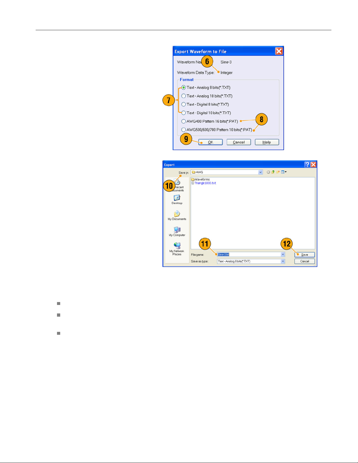
6. This is an example of a dialog box when
you export an Integer format waveform
in an AWG7000 s
eries instrument.
Saving and Recal
ling Setups
7. You c a n select
you select a *.txt format. Select Digital
to specify each bit for DAC.
8. You can export an Integer format
waveform int
the AWG400/500/600/700 series
instruments.
9. Click OK. The Export dialog box shown
in step 10 i
10. Select a location to save the waveform
data in Save in box.
11. The waveform name you selected in the
Waveform List window is displayed.
12. Click Save. You can export the selected
waveform data as a specified file format.
Analog or Digital when
o a *.pat file for
s displayed.
Quick Tips
Analog data is exported as normalized value.
You can select DAC resolution when an Integer waveform is exported. The s elected DAC resolution is used to convert
integer data to normalized value.
To change waveform format (Real or Integer), use the Waveform Properties dialog box. (See page 57, Confirming
form Properties.)
Wave
AWG5000 and AWG7000 Series Quick Start U ser Manual 49

Waveform Displa
y and Edit
Waveform Disp
Waveform Window
You can use the Waveform window to edit a newly created waveform or user-defined waveform listed in the Waveform List
window. A selected element in the Sequence window or a selected waveform on the Ch n page of the Settings window is
displayed in the Waveform window.
1. This is an example of Graphic display.
Analog data and markers for Ch 1 and
Ch 2 are displayed.
2. Click this icon to toggle graphic display
and table display.
3. Click this icon (Vertical Best Fit) to adjust
analog channel height so that all the
elements are contained in the Waveform
window.
lay and Edit
4. This is an example of Table display.
You can select either Analog or Digital in
the Table display. This example shows
Digital display with binary format.
Quick Tips
You can select displayed items in the Waveform window from analog data only, marker data only, or analog and
marker data.
To remove waveform data from the Waveform window, select Edit > Clear from the menu bar.
You can select the vertical and horizontal units using the Display Properties dialog box. (See page 29, Changing the
Windows Display Style.)
To set a waveform from the Waveform List window, select a waveform and drag and drop it to the Waveform window.
50 AWG5000 and AWG7000 Series Quick Start User Manual

Using Zoom
Use Zoom when you want to temporarily look at details of a waveform. To magnify a waveform, select Zoom commands from
the View menu, or use the Zoom icons. The choices are as follows:
1. Zoom In –UseZoom In to magnify a
waveform horizontally and vertically at
the same time.
2. Horizontal Zoom In –UseHorizontal
Zoom In to magnify a waveform
horizontally.
3. Vertical Zoom In –UseVertical Zoom
In to magnify a waveform vertically.
Youcanselecttheverticalscale
definition when zooming vertically.
Use the Preferences dialog box. (See
page 28, Setting the User Preferences.)
4. Zoom Out –UseZoom Out to return the
previous zoom factor. You can use Zoom
Out only after the waveform is magnified.
Waveform Displa
y and Edit
5. Fit to Window –UseFit to Window to fit
the waveform in the window and restore
the waveform to its state before the first
zoom in. You can use Fit to Window only
after the waveform is magnified.
6. The fastest way to set up a zoom display
is to use Zoom icons on the Waveform
window.
Select one of the Zoom icons, and then
click and drag across the segment of the
waveform to create a box for zooming, or
just click a point in the waveform.
AWG5000 and AWG7000 Series Quick Start U ser Manual 51

Waveform Displa
y and Edit
Creating or Modifying a Waveform
Use the Edit menu to create a new waveform or modify an existing waveform.
Use Undo to cancel the last process and
Redo to repeat the last process.
Undo does not apply to cursor position,
zoom, and scroll functions.
Use Create Analog Waveform or
Create Digital Pattern to open dialog
boxes to create waveforms or digital
patterns.
Use Equation Editor to open the
Equation Editor to create equations to
create complex waveforms.
Use the basic editing controls to cut,
copy, paste, and delete waveforms.
In the sequence or subsequence, Cut,
Copy, or Delete causes an immediate
action.
Use Delete All Waveforms to delete
all of the user-defined waveforms in the
setup file.
Use Clear to remove the content of
selected elements in the Sequence
window. Remaining elements do not
shift.
In the Waveform window, Clear removes
the selected waveform data.
52 AWG5000 and AWG7000 Series Quick Start User Manual

Creating a Standard Waveform
You can create a new waveform using the Create A nalog Waveform dialog box.
1. Select Edit > Create Analog Waveform
to open the Create Analog Waveform
dialog box.
Waveform Displa
y and Edit
2. Use Fu ncti
type. You can select a waveform from
Sine, Triangle, Square, Ramp, Gaussian
Noise, an
3. Use Timin
Frequency, Waveform Length, and
Cycle.
4. Select Auto or No Change in Sampling
Rate.
5. A waveform is displayed on the Preview
screen.
on to select a waveform
d DC.
g to set parameters for
Auto Sam
length are automatically set to
appropriate values.
No Change Sampling rate is not
change
two parameters from frequency,
waveform length, and cycle.
The re
calculated automatically.
pling rate and waveform
d. You can select any
maining parameter will be
AWG5000 and AWG7000 Series Quick Start U ser Manual 53

Waveform Displa
6. Use Level to set parameters for
Amplitude/Offset or High/Low.
7. Use Option to select the amplitude/
offset settin
when you set the vertical units to Voltage.
If you s et the vertical units to Normalized
Value, this f
page 29, Changing the Windows Display
Style.)
8. Select an edit action in the Operation
frame.
y and Edit
gs. This frame is displayed
rame is disabled. (See
Set to –Spe
and index number. The created
waveform is assigned to the specified
position.
Insert bef
waveform is inserted before the
specified cell of the sequence. When
this com m
remaining data is shifted. When the
Run mode is non-sequence, this
paramet
Create O
waveform, but the waveform is not
loaded. Enter the waveform name
in the W
created waveform is listed in the
Waveform List window.
Overwrite – Specified existing
wavef
you select O verwrite, a waveform
currently being loaded is displayed in
the Ta
Waveform Name box is disabled.
cifies the channel
ore – The created
and is executed, the
er is disabled.
nly – Creates a new
aveform Name box. The
orm data is overwritten. When
rget Waveform Name box. T he
9. Click Execute to create a waveform.
Quick Tip
Use Create Digital Pattern to create digital patterns in a similar manner as creating Analog waveforms.
54 AWG5000 and AWG7000 Series Quick Start User Manual
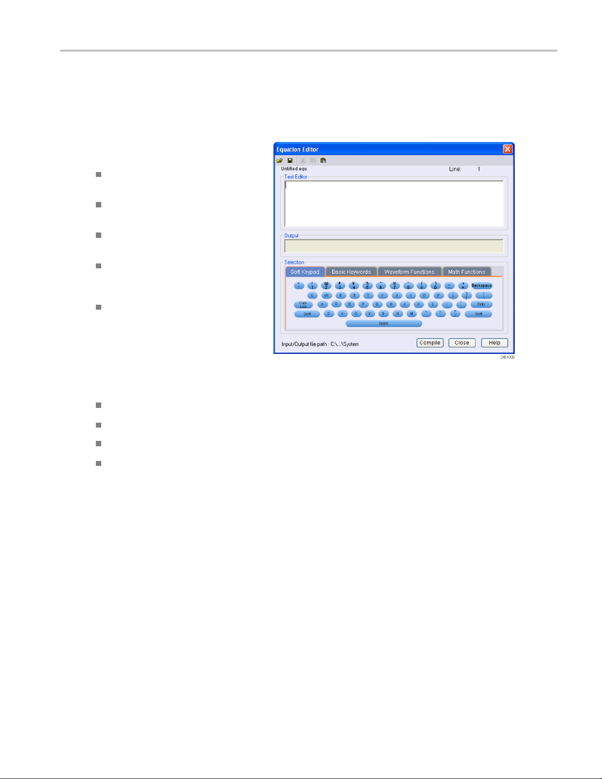
Equation Editor
Waveform Displa
y and Edit
The Equation E
files. The editor p rovides control and flexibility to create more complex waveforms than using the Create Analog Waveform or
Create Digital Pattern tools alone. Access the editor from the Edit menu.
The following list provides some limitations
and guidelines for using the Equation Editor.
The m aximum number of characters in a
text string i
The maximum
lengths) in a program is 1000.
The Equation Editor only supports the
7-bit ASCII character set.
Concatenate strings with a colon. An
example of
inastringis“AA”:i:”Value”.
Click the icons in the tool bar for
operations such as open, save, cut,
copy, and
ditor i s an ASCII text editor that uses text strings to create waveforms by loading, editing, and compiling equation
s 256, including spaces.
length (sum of all string
embedding a numeric value
paste.
Click the tabs to access tools to help create or modify equations:
The Soft Keypad provides an on-screen keyboard for entering data and characters directly.
Use the Basic Keywords tab to quickly enter prede fined variables and control statements.
Use the Waveform Functions tab quickly enter common waveform functions.
Use the Math Functions tab to quickly enter math func tions to use as part of a waveform equation expression.
Refer to the online help for additional information on the equation editor and the waveform functions.
AWG5000 and AWG7000 Series Quick Start U ser Manual 55

Waveform Displa
y and Edit
Accessing Waveform in a Setup File
A created waveform is registered as a user-defined waveform in the Waveform List window. T he Waveform List window lists the
waveforms that are saved in the setup files (*.awg).
1. To select a predefined waveform, click
the Predefined tab.
2. Predefined waveforms have an asterisk
sign (*) to th
NOTE. You cannot edit, delete, or rename
the predefined waveforms.
3. To select a user-defined waveform, click
the User Defined tab.
To edit a user-defined waveform,
select the waveform and drag it to the
Waveform window.
e left of the waveform name.
4. You can sort the waveform list by the
order of Waveform Name, Length, or
Date.
5. Each waveform length is displayed as a
three-digit number in the Waveform List
window.
6. If you want to know the exact waveform
length, select the waveform and then
right-click to display the pop-up menu.
Select Waveform Properties to display
the Waveform Properties dialog box. You
can confirm the waveform length with
this dialog box.
Quick Tips
If you right-click this window, a pop-up menu displays. You can access the commands, s uch as Delete, Copy, and Paste.
When you create a waveform, you cannot use the same name as a predefined waveform.
56 AWG5000 and AWG7000 Series Quick Start User Manual
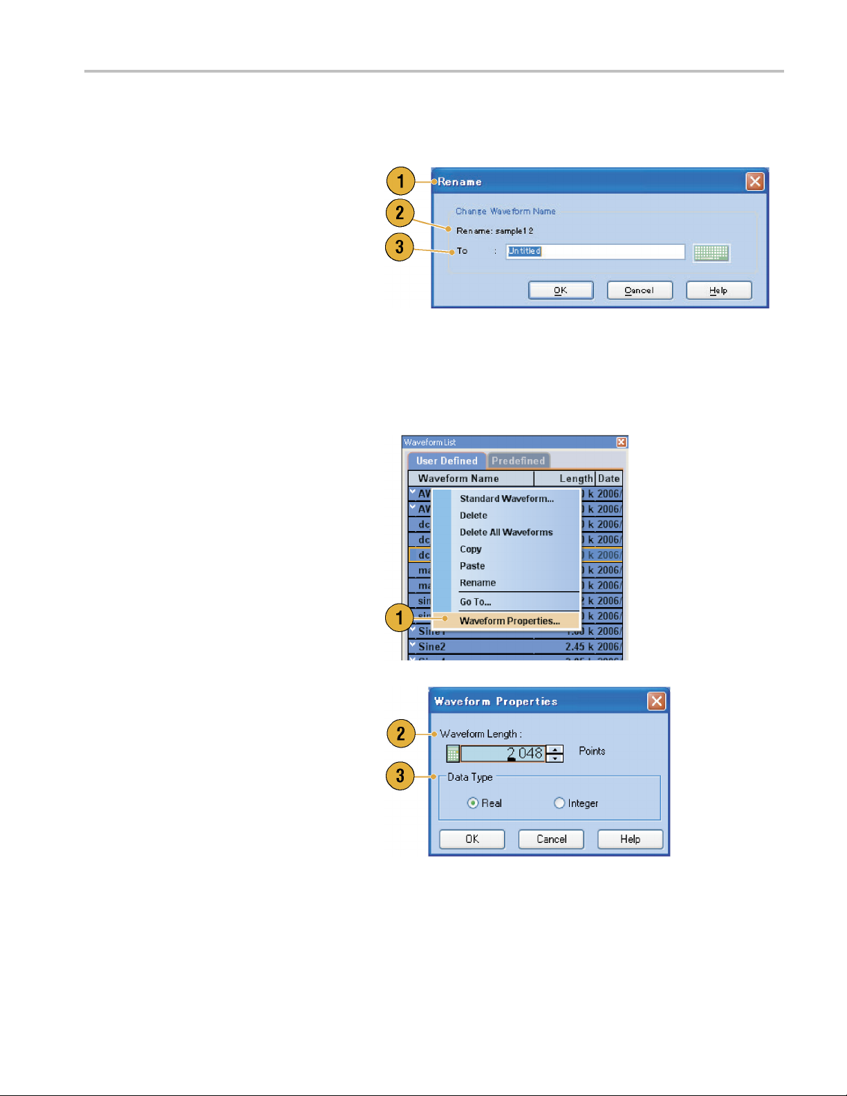
Changing a User-Defined Waveform Name
You can change a user-defined waveform name in the Waveform List window.
Waveform Displa
y and Edit
1. Select a wavef
window, and then select Edit > Rename
from the menu bar to open the Rename
dialog box.
2. The waveform
3. Enter the ne
field.
orm in the Waveform List
name is displayed.
w waveform name in the To
Confirming Waveform Properties
You can confirm or change properties of waveform data using the Waveform Properties dialog box.
1. Select a waveform in the Waveform
List window, and then select Waveform
Properties from the popup menu to
display the dialog box.
You can access the Waveform Properties
dialog box by right-clicking in the
Waveform window or the Ch n page of
Settings window.
2. You can confirm or change the waveform
length.
3. You can confirm or change the waveform
ype (Real or Integer).
data t
AWG5000 and AWG7000 Series Quick Start U ser Manual 57

Waveform Displa
y and Edit
Editing a Waveform
You can edit a waveform which is created using the S tandard Waveform dialog box, imported w aveform, or a user-defined
waveform listed in the Waveform List window.
Item and Range
When you edi
1. To edit a waveform, you can use these
menu items.
2. You can select edit item(s) from the
following
3. You ca
following:
t a waveform, items and range are usually specified as an edit target.
:
Ch n Analog
ChnMarke
All - Edit
can be target of an edit operation
such as Cut or Copy.
All Analog - Edit is applied to all
analog d
selected when Scale or Offset is
selected.
All Markers - Edit is applied to all
marker
n select edit range from the
All - Edit is applied to all the range of
selected item(s).
data
r 1 data/Marker 2 data
is applied to all items. All
ata. All Analog can be
data.
Between Cursors - Edit is applied to
ange between cursors.
the r
cted - Edit is applied to selected
Sele
range. This selection is available
only in the Table display
NOTE. The internal clipboard resides in the instrument application software. It is different from Windows clipboard. You
cannot transfer data from other applications like Microsoft Excel i nto the instrument clipboard. Data transfer from other
applications is possible using the import/export functions.
58 AWG5000 and AWG7000 Series Quick Start User Manual

Waveform Displa
y and Edit
Cut and Paste Example
The following procedure shows Cut and Paste example in the Waveform window (Graphic display). You can also execute
Cut or Paste in the Table display.
1. Select the item(s) you want to edit. This
example shows cut and paste operation
using two channels.
2. Specify the range using cursors.
3. Select Edit > Cut to open the Cut dialog
box. Select the following:
Item – Selected
Range – Between Cursors
If you need to change the Items or Range
settings, use this dialog box.
4. Click OK.
5. The selected part of the waveform is cut.
NOTE. If a part of items are cut or deleted,
the waveform length will not be shortened.
The data is shifted. The part after the shifted
area will be filled with default value.
NOTE. If all items are cut or deleted, the
waveform length is shortened accordingly.
AWG5000 and AWG7000 Series Quick Start U ser Manual 59

Waveform Displa
6. Select Ch 2.
7. Specify the edit target using the cursors.
From the Edit menu, select Copy.
y and Edit
8. This is an e
xample of Paste-Replace.
The specified range of Ch 2 waveform is
pasted and replaces the Ch 1 waveform.
TheCh1wa
veform length is not
changed.
9. This is an example of Paste-Insert.
The specified range of Ch 2 waveform
is inserted on the Ch 1 waveform. The
Ch 1 waveform length is changed.
60 AWG5000 and AWG7000 Series Quick Start User Manual

Math Waveforms
You can use the Math dialog box to perform mathematical operations on the waveform you are editing. The analog data of
two w aveforms can be added, subtracted, or multiplied. The created waveform data can be added to the Waveform List.
1. Select Tool s > Math to display the Math
dialog box.
2. You can enter a waveform name in the
New Waveform field.
3. Select a waveform from the waveform
list. Click the icon to display the
Waveform List dialog box.
4. Select a math operator.
5. (AWG7000 series) Select the resolution.
6. If you click Show Preview,the
calculation results will appear on the
Preview screen.
Waveform Displa
y and Edit
7. Click OK to add the new waveform to the
Waveform List window.
Quick
Tips
A new waveform will be created as the result of waveform math operation. For the marker data, the data of the first
operand waveform will be copied to the new waveform.
The math operation is executed for all analog waveform data.
If the length of two waveforms is not the same, the length of the result is the same as the length of the shorter waveform.
The beginning part of the longer waveform is used for the calculation.
AWG5000 and AWG7000 Series Quick Start U ser Manual 61

Waveform Displa
y and Edit
Normalize Option
You can select normalize options when analog data is normalized. Normalize is executed for the entire analog waveform data.
Select one of t
Tools menu:
1. Fit to DAC range, preserve offset
The waveform data is scaled relative to
0(zero).
2. Fit to full D
Minimum value goes to
–1.0 in normalized value and
the maximum
+1.0 in normalized value.
he following options from the
AC range
value goes to
Using Other Edit Menu Commands
Scale. You can scale the specified range of analog data using Scale from the Edit menu.
1. Vertical
2. Use this dialog box to change the Item or
scale origin and scale factor can
be set. The scale factor does not have
the units.
Range. (
See page 58, Item and Range.)
62 AWG5000 and AWG7000 Series Quick Start User Manual

Offset. You can add constants to the specified range of analog data using Offset from the Edit m enu.
1. Offset can be set by voltage or
normalized value.
2. Use this dialog box to change the Item or
Range. (See pa
ge 58, Item and Range.)
Waveform Displa
y and Edit
Invert. D
1. For analog data, a positive value will
ata values in the specified range can be inverted using Invert from the Edit menu.
become negative. For marker data, low
(0) becom
Use this dialog box to change the Item or
Range. (See page 58, Item and Range.)
es high (1).
AWG5000 and AWG7000 Series Quick Start U ser Manual 63
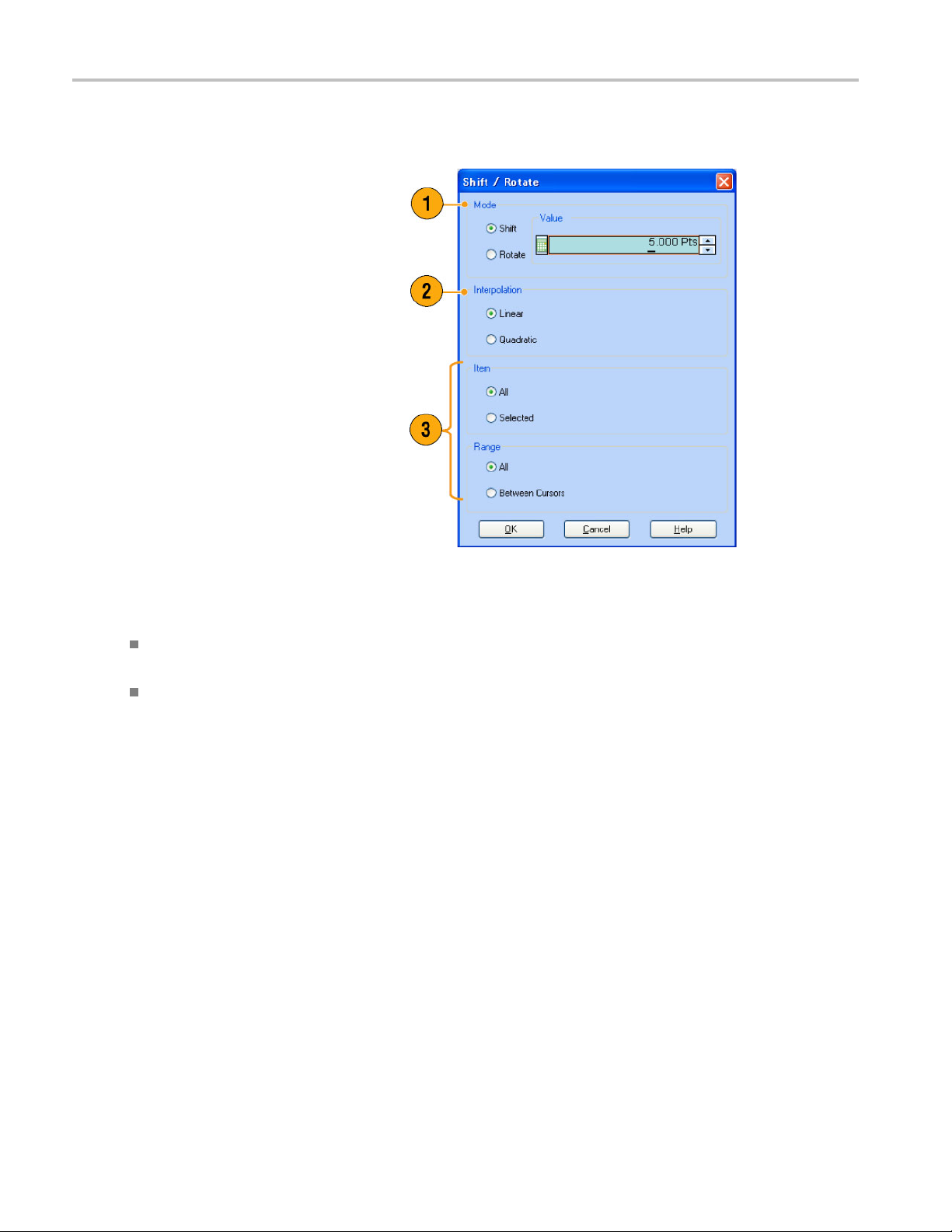
Waveform Displa
Horizontal Shift/Rotate. You can shift or rotate the specified range of waveform data horizontally using Shift/Rotate
from the Edit me
1. Select Mode (Shift or Rotate).
You can set the
(time or points).
2. Linear or Quadratic interpolation can be
selected for fractional shift or rotation.
3. Use this dialog box to change the Item or
Range. (See p
y and Edit
nu.
shift or rotate values
age 58, Item and Range.)
Quick Tips
Horizontal Rotate is used to check if the waveform data is connected smoothly from the end of the first waveform to the
beginning of the second waveform. This is especially useful when the waveform is looped by the sequencer.
Horizontal Shift/Rotate is applied for analog data and marker.
64 AWG5000 and AWG7000 Series Quick Start User Manual

Waveform Displa
y and Edit
All High/All Low. You can set the specified range of data to high or low using All High/All Low from the Edit > Modify
Pattern menu.
1. Select All High or All Low.
2. Change the Level parameters, if needed.
3. Select the Item and Range.
PRBS. You
1. Select a PRBS pattern from the Equation
list.
2. Select a
3. Change t
4. Select t
can replace a speci fied range of data with a PRBS pattern using PRBS from the Edit > Modify Pattern menu.
Mark Density.
he Level parameters, if needed.
he Item and Range.
AWG5000 and AWG7000 Series Quick Start U ser Manual 65
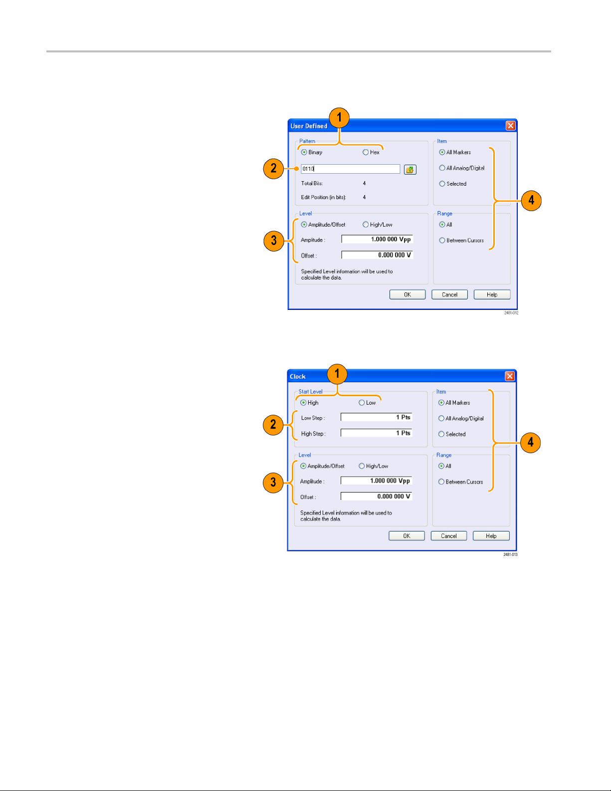
Waveform Displa
User Defined. Yo u c a n fill the specified range of waveform data with a selected digital pattern using User Defined from the
Edit > Modify Pa
1. Select Binary or Hex for the pattern.
2. Enter a pattern directly, or load a text
file from the in
external memory device.
The maximum length of a bit pattern is
1000 (250 Hex
y and Edit
ttern menu.
ternal hard drive or an
characters).
3. Change the Le
4. Select the I
If multiple items are specified as the
target, the same data is created for all
items.
Clock. Yo
1. Select the Start Level.
2. Enter the values for Low Step and High
Step.
3. Change t
4. Select t
vel parameters, if needed.
tem and Range.
ucanfill a specified range of data with a clock pattern using Clock from the Edit > Modify Pattern menu.
he Level parameters, if needed.
he Item and Range.
66 AWG5000 and AWG7000 Series Quick Start User Manual

Waveform Displa
y and Edit
Binary Counter. You can fill the specified range of data with a binary counter pattern using Binary Counter from the Edit >
Modify Pattern
1. You can select the direction (Up counter
or Down counte
The up counter begins from all 0, and the
down counter begins from all 1.
2. Change the Level parameters, if needed.
3. Select the Item and Range.
menu.
r).
AWG5000 and AWG7000 Series Quick Start U ser Manual 67
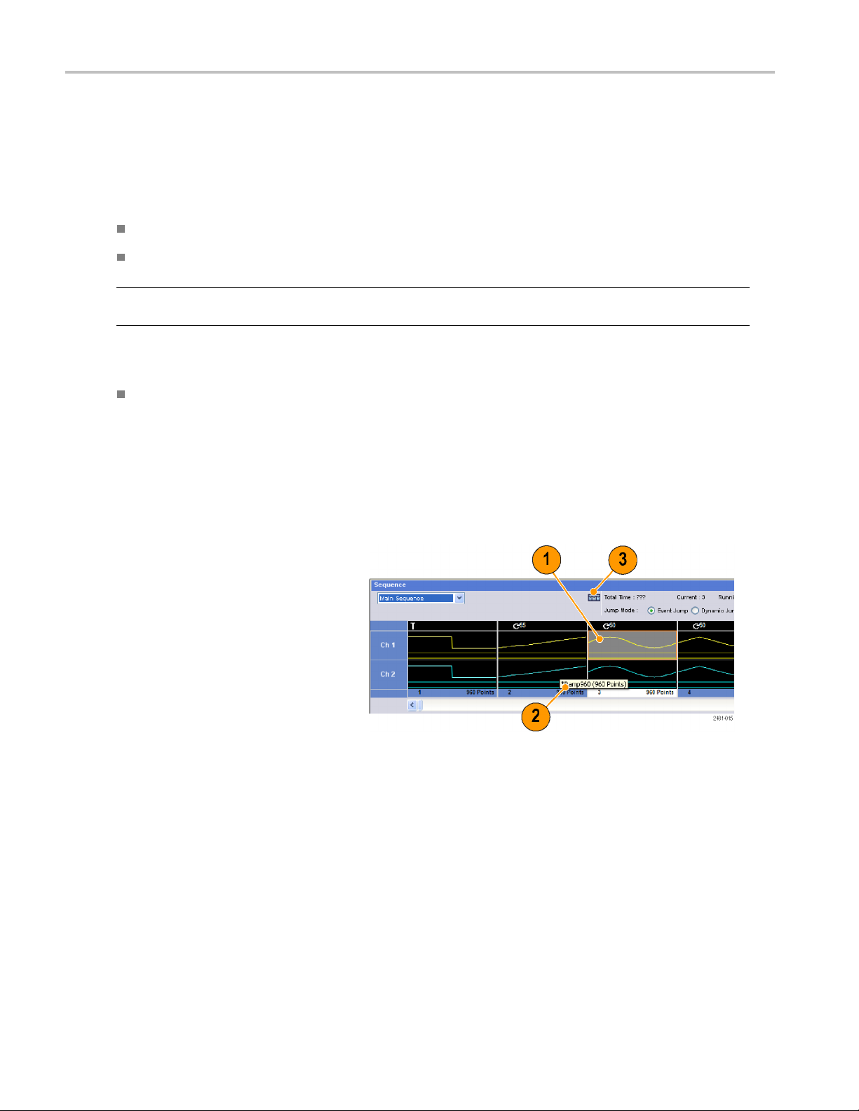
Sequence
Sequence
It is sometimes necessary to create long waveform files to fully implement a DUT test. Where portions of the waveforms are
repeated, a waveform sequencing function can save you a lot of memory-intensive waveform programming.
Sequence is used for mainly the following two purposes:
Output longer waveform than hardware m emory
Change the output waveform quickly (such as ATE applications)
NOTE. Wait Trigger is set to On in an instrument without option 08. To set Wait Trigger Off, option 08 must be installed in
the instrument.
Quick Tip
For instru
sequences alone.
ments with Option 09, use subsequences with sequences to create longer waveform files, rather than using
Sequence Window
When Sequence is selected in the Run Mode, this window shows information on the status of the sequence settings. (See
page 23, Run Mode.)
This is an example of the Sequence window
Thumbnail display.
1. If you click a cell, the selected waveform
layed in the Waveform window.
is disp
The background color of the selected
cell changes.
2. If you hover the mouse over a sequence
a tooltip appears to show you the
cell,
waveform name and waveform length.
3. Click Switch to Table to change the
display to Table display.
68 AWG5000 and AWG7000 Series Quick Start User Manual

This is an example of Table display. You can
directly enter a sequence parameter value,
such as Repeat
Table display.
count or Go To target, in the
Quick Tips
The following methods are available for applying an existing waveform to a sequence:
Drag and drop a waveform from the Waveform List window to a cell of the Sequence window
After selecting a cell in the Sequence window, use Set Waveform or Insert Waveform from the Edit menu
When Continuous, Triggered, or Gated is selected in the Run mode, the Sequence window is hidden.
The following icons are used in the Sequence window:
Sequence
Display icons Description
gger
Wait Tri
. (Repeat count is set to 26 in this example.)
Repeat
Repeat (Infinite)
Event Jump. (Jump target is set to index number 26 in this example.)
Go To. (Go To target is set to index number 26 in this example.)
quence
Subse
AWG5000 and AWG7000 Series Quick Start U ser Manual 69

Sequence
Creating a Sequence
To create a sequence, waveforms must be assigned to Sequence window. The following example shows basic steps to
create a sequence.
1. Select a waveform in the Waveform List
window.
2. Drag and drop the waveform to a
sequence window cell.
As a quick access to the waveform list,
you can double-click or right-click a cell.
3. After assigning waveforms to sequence
cells, you can define the sequence
parameters.
Right-click a cell, or use the Edit menu to
open the Sequence Control Parameters
dialog box.
4. The sequencer will wait for the trigger
before generating a waveform if Wait
Trigger is checked.
5. A waveform can be repeated if the
Repeat Count is specified for each
element of the sequence.
6. Event Jump To changes the sequencing
of the waveform by the external event.
See the Quick Tips below for supported
event signals.
7. If you specify Go To target for each
sequence element, the sequencer
jumps to the element specified by Go
To target immediately after generating
the waveform specified in a sequence
element.
70 AWG5000 and AWG7000 Series Quick Start User Manual

8. A sequence element consists of all
analog waveform data and marker data
with an index n
umber.
Sequence
9. A selected ele
element.
10. A selected element in the Sequence
window will be displayed in the Waveform
window.
ment is called current
Quick Tips
You can use the Standard Waveform dialog box to create a waveform and set the waveform to Sequence window.
When importing waveform data, you can directly set the waveform to Sequence window.
If Sequence is selected in the Run mode, the sequencer executes the sequence definition. Sequence definition consists
of a series of sequence elements. Each sequence element has the following information:
References to the waveform for each channel
Sequence control parameters (Wait, Repeat, Event Jump To and Go To)
Sequence is executed in turn from the first element (Element Index = 1) to the last element. If an element has Jump To or
the sequencer follows that definition.
Go To,
llowing signals are supported as an event:
The fo
al is applied to the front-panel Event Input connector
Asign
ront-panel Force Event button is pushed
The f
te command is received – EVEN t[:IMM ediate]
Remo
mum sequence length is different depending on the instrument type.
Maxi
Instrument type Maximum sequence length
AWG7000 series
AWG5000 series
1 to 16,000 steps
1 to 8,000 steps
AWG5000 and AWG7000 Series Quick Start U ser Manual 71
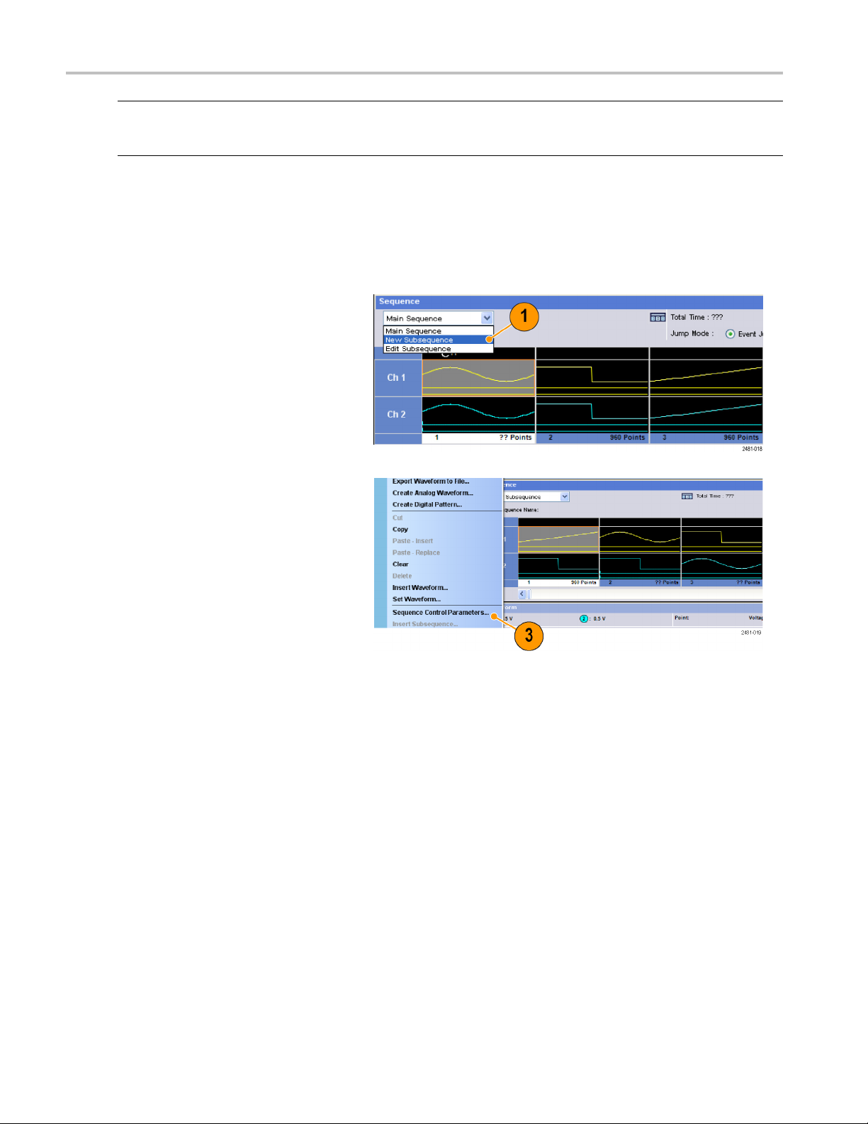
Sequence
NOTE. There are two sequencer modes in the arbitrary waveform generator to execute the created sequence: the hardware
sequencer mode
hardware and software sequencer modes.
and the software sequencer mode. Refer to the online help for details about the difference between the
Creating a Su
Subsequences are sequences that can be recalled from existing sequences. Sequences can have more than one
subsequences, but subsequences cannot have subsequences. Subsequences are available with instruments with Option 09.
For more information on using subsequences, refer to the online help.
1. Select New Subsequence from the
drop-down list in the Sequence window.
2. Add waveforms as needed to the new
subsequence. (See page 70, Creating a
Sequence.)
3. Right-click the cell and select Sequence
Control Parameters.
bsequence
72 AWG5000 and AWG7000 Series Quick Start User Manual

4. Specify the repeat count for each
subsequence element.
Sequence
NOTE. You cann
infinity for a subsequence element.
5. After defi
the subsequence, you must name the
subsequence. Right-click the mouse and
select Na
ot set the Repeat Count to
ning all of the elements in
me Subsequence.
6. Enter a
name for the new subsequence.
The new subsequence is added to the
list of subsequences in the Waveform
indow.
List w
AWG5000 and AWG7000 Series Quick Start U ser Manual 73

Sequence
Editing a Sequence
The following commands are provided for sequence edit:
Set Waveform a
nd Insert Waveform.
Use these menus to set or insert a waveform to a Sequence window cell.
Clear. Clear removes the contents of selected element(s). Yo u can clear multiple non-contiguous elements. Unselected
elements do not shift.
Cut and Delete. Cut and Delete can be done by the units of element. You can cut or delete multiple and continuous
elements at a time.
Copy, Paste-Insert and Paste-Replace. You can copy or paste data on one or more contiguous elements. The
data in the clipboard will be inserted or replaced at the specified position of the sequence. If Paste-Insert is executed,
the existing data is shifted.
Edit Example
The following procedure shows Cut and Paste example in the Sequence window (Table display).
1. Create a sequence.
2. Select the element(s) to cut. In this
example, Index number 3 is the target
of Cut.
NOTE. You can Cut and Delete at the units
of element level.
74 AWG5000 and AWG7000 Series Quick Start User Manual

3. Cut is executed and the r emaining data
in the sequence are shifted.
Sequence
NOTE. Cut data
Deleted data is removed from the sequence
and cannot be recovered.
4. Clear initializes the data o f selected
waveform(s
cell becomes Empty.
5. Use Inse
waveform from the Waveform List.
6. You can use Paste-Insert or
Paste-Replace when you want to
set a wa
waveform in the Sequence window.
is placed in the clipboard.
) or element(s). A cleared
rt Waveform to insert a
veform after copying any
AWG5000 and AWG7000 Series Quick Start U ser Manual 75

Sequence
Event Jump
Use the Event page of Settings window to set parameters for event signal. You can use the Event page when the Run
mode is Sequence.
1. Sets external event input threshold level.
2. Selects the polarity of external event
input signal (Positive or Negative).
Positive – Jump will occur when the
instrument receives a positive pulse.
Negative – Jump will occur when the
instrument receives a negative pulse.
3. Sets jump timing (Async or Sync).
Async – Jump will occur immediately.
Sync – Jump will occur after the
waveform is generated.
4. Sets event input impedance (1 kΩ or
50 Ω).
Quick Tips
Event Jump can change the sequence order using an event signal.
Jump timing is applied to both Event Jump and Force Jump.
76 AWG5000 and AWG7000 Series Quick Start User Manual

Force Jump To
Force Jump allows you to jump to a position that you choose while the instrument is outputting a sequence.
Select System > Force Jump To to open
the Force Jump To dialog box.
1. Specify a jump target or select Index No.
2. When Index No is selected as jump
target, enter the index number using the
Value: field.
3. Click Jump Now to change the waveform
output to the position specified by jump
target.
Quick Tips
The arbitrary waveform generator has an Event Jump function which changes the sequence using an event signal. Use
the Event page of the Settings window to set parameters for Event Jump.
Sequence
Force Jump is similar to Event Jump. In the case of Force Jump, you must specify the jump target explicitly by using the
ForceJumpTodialogbox.
Force J ump is independent from Event Jump. Force Jump can be executed regardless of the Event Jump setting.
AWG5000 and AWG7000 Series Quick Start U ser Manual 77

Sequence
Accessing Sequence Elements Outside the Display Area
When you create a long sequence, the Sequence window cannot display the whole sequence elements. You can use the Go
To dialog box to move to a specified element that is not displayed in the window.
1. After creating a sequence, select View >
Go To or select Go To from the popup
menu.
Thedialogboxshowninstep2is
displayed.
2. Select Index No as a Go To target.
3. Enter a value.
4. Select OK intheGoTodialogbox. The
display will jump to the specified position.
kTip
Quic
You can also use the Go To dialog box in the Waveform or Waveform List window.
78 AWG5000 and AWG7000 Series Quick Start User Manual

Tutorials
The examples in this section show how to use your instrument to do common arbitrary waveform generator tasks. These
examples use the dual-channel model.
Creating and Editing a Waveform
1. Recall the default s etup.
2. Select Continuous from the Run Mode
page of the Settings window.
Tutorials
3. Use the Standard Waveform dialog box
to create the following square waveform:
Waveform Length: 960 points
Cycles: 5
Amplitude: 1.0 Vp-p
Offset: 0.5 V
4. Set the waveform created in step 3 to
Ch 1.
5. Assign the waveform name “Ch1-Square”
to the waveform.
AWG5000 and AWG7000 Series Quick Start U ser Manual 79
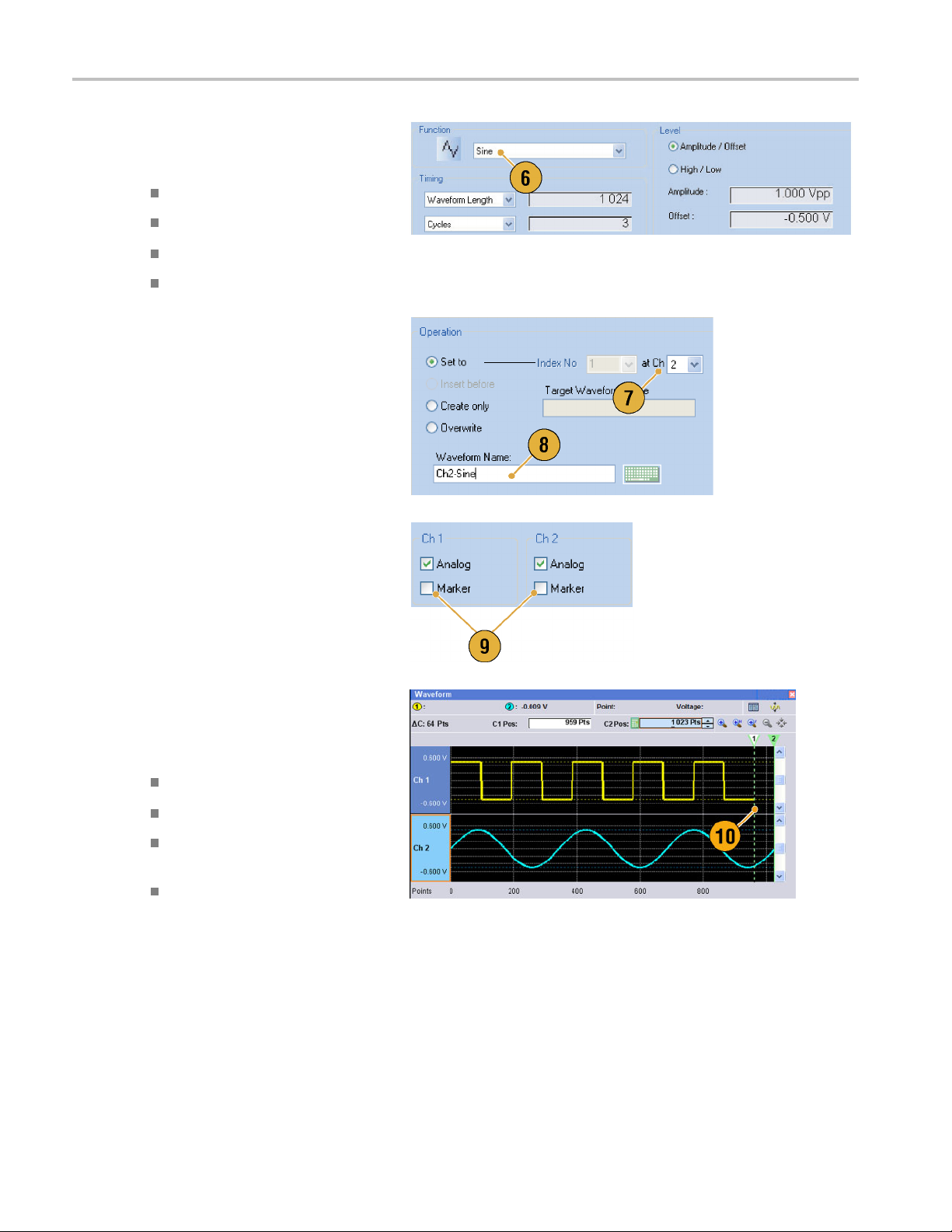
Tutorials
6. Use the Standard Waveform dialog
box to create the sine waveform shown
below:
Waveform Leng
Cycles: 3
Amplitude: 1
Offset: –0.
7. Set the wave
Ch 2.
8. Assign the waveform name “Ch2-Sine”
to the waveform.
9. To edit analog waveform data, hide the
Ch1andCh2Marker data using the
Display Properties dialog box.
th: 1024 points
.0 Vp-p
5V
form created in step 6 to
10. Delete points from the end of the Ch 2
waveform to make it the same length as
the Ch 1 waveform.
Use cursors to set the range.
Position the cursors as shown.
Select the Ch 2 waveform.
Right-click and select: Delete,
Selected, Between Cursors.
Click OK.
80 AWG5000 and AWG7000 Series Quick Start User Manual

11. Ch 1 and Ch 2 waveforms have the
same waveform length. You can now
output the sig
12. Save the setup.
nal.
Tutorials
Creating and Editing a Sequence
1. Recall the default s etup.
2. Select Sequence from the R un Mode
page of the Settings window.
AWG5000 and AWG7000 Series Quick Start U ser Manual 81

Tutorials
3. Select *Sine960 from the Predefined
page of the Waveform List window,
and drag and dr
Ch 1 sequence.
4. Similarly, select *Triangle960 from
the Waveform List window, and set
the waveform
Ch 1 sequence.
5. Create a sine waveform with the following
attributes and set the waveform to the
third cell of Ch 1 sequence.
Waveform Length: 960 points
op it to the first cell of
to the second cell of
Cycles: 5
Amplitude: 1.0 Vp-p
Offset: 0.0 V
Waveform Name: Sine-1
6. Select third cell of sequence, and select
om the popup menu.
Copy fr
7. Sele
ct second cell of sequence, and
select Paste-Insert from the popup
menu.
82 AWG5000 and AWG7000 Series Quick Start User Manual
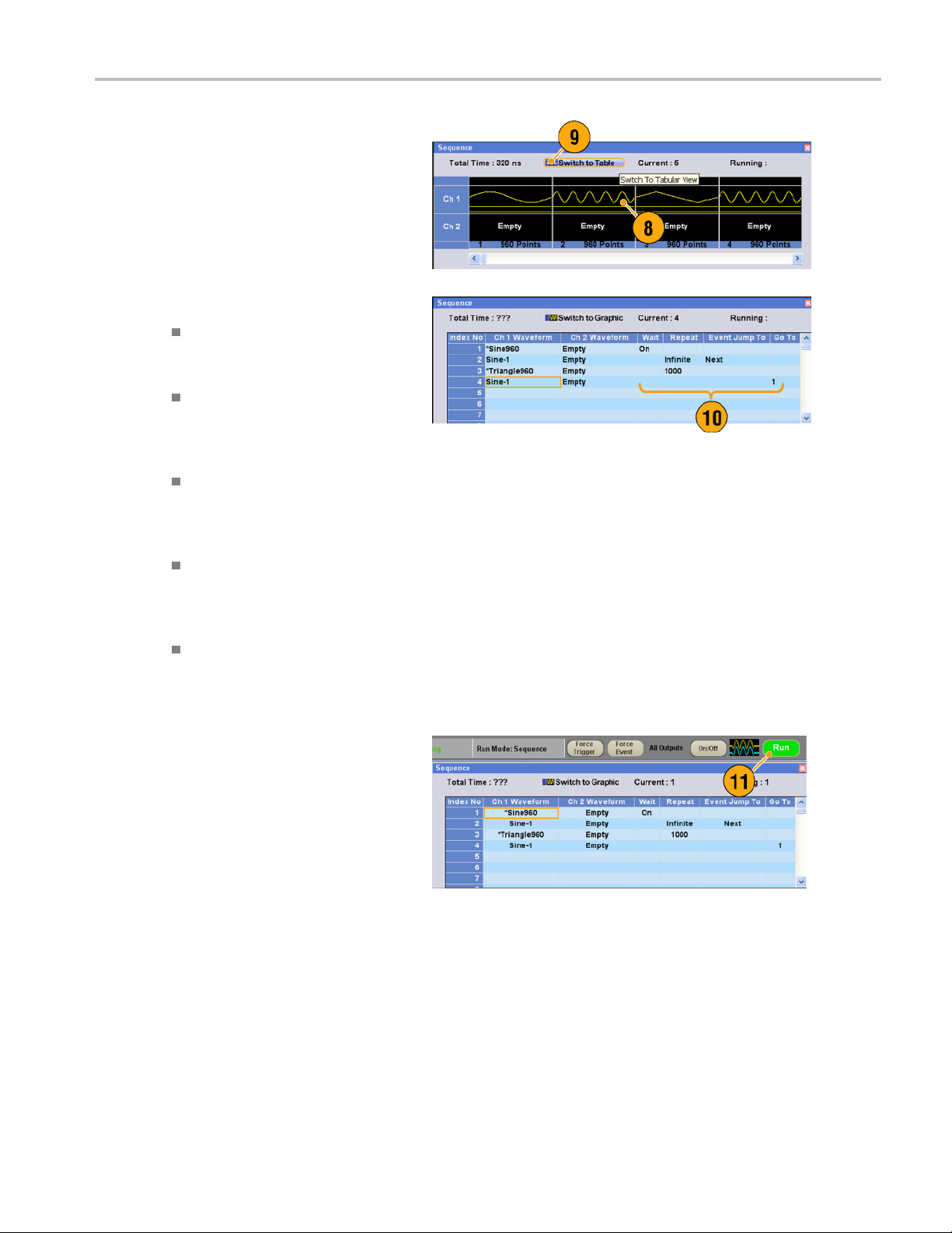
8. The copied waveform is pasted to
index 2.
9. Click the Switch to Table icon to change
the display to
Tabular view.
Tutorials
10. Set the foll
11. Click the Run button to confirm that the
seque
window next to the Run button will be
activated when the instrument is in the
runn
owing sequence parameters:
Index 1: Wai
The sequence waits for a trigger
before generating the first element.
Index 2: Repeat count Infinite
The sequen
the Sine-1 waveform until an event
occurs.
Index 2: Event Jump To Next
When the i
event signal, the sequence jumps to
next element.
Index 3: Repeat count 1000
The sequ
*Triangle960 waveform 1000
times.
Index 4: Go To 1
The seq
number 1 after generating index
number 4 waveform.
nce w orks properly. The animation
ing state.
t Trigger On
ce infinitely generates
nstrument receives an
ence repeats the
uence jumps to index
AWG5000 and AWG7000 Series Quick Start U ser Manual 83

Tutorials
84 AWG5000 and AWG7000 Series Quick Start User Manual
 Loading...