


x
AWG5000 and AWG7000 Series
Arbitrary Waveform Generators
ZZZ
Quick Start User Manual
*P071248104*
071-2481-04


xx
AWG5000 and AWG7000 Series
Arbitrary Waveform Generators
ZZZ
Quick Start User Manual
www.tektronix.com
071-2481-04

Copyright © Tektronix. All rights reserved. Licensed software products are owned by Tektronix or its subsidiaries or suppliers, and are
protected by na
tional copyright laws and international treaty provisions.
Tektronix pro
previously published material. Specifications and price change privileges reserved.
TEKTRONIX and TEK are registered trademarks of Tektronix, Inc.
ducts are covered by U.S. and foreign patents, issued and pending. Information in this publication supersedes that in all
Contacting Tektronix
Tektronix, Inc.
14150 SW Karl Braun Drive
P.O. Box 500
Beaverton, OR 97077
USA
For product information, sales, service, and technical support:
In North America, call 1-800-833-9200.
Worldwide, visit www.tektronix.com to find contacts in your area.

Warranty
Tektronix warrants that this product will be free from defects in materials and workmanship for a period of one (1) year from the date of
shipment. If any such product proves defective during this warranty period, Tektronix, at its option, either will repair the defective
product without charge for parts and labor, or will provide a replacement in exchange for the defective product. Parts, modules and
replacement products used by Tektronix for warranty work may be new or reconditioned to like new performance. All replaced
parts, modules and products become the property of Tektronix.
In order to obtain service under this warranty, Customer must notify Tektronix of the defect before the expiration of the warranty period
and make suitable arrangements for the performance of service. Customer shall be responsible for packaging and shipping the
defective product to the service center designated by Tektronix, with shipping charges prepaid. Tektronix shall pay for the return of the
product to Customer if the shipment is to a location w ithin the country in which the Tektronix service center is located. Customer shall
be responsible for paying all shipping charges, duties, taxes, and any other charges for products returned to any other locations.
This warranty shall not apply to any defect, failure or damage caused by improper use or improper or inadequate m aintenance and
care. Tektronix shall not be obligated to furnish service under this warranty a) to repair damage resulting from attempts by personnel
other than Tektronix representatives to install, repair or service the product; b) to repair damage resulting from improper use or
connection to incompatible equipment; c) to repair any damage or malfunction caused by the use of non-Tektronix supplies; or
d) to service a product that has been modified or integrated with other products when the effect of such modification or integration
increases the time or difficulty of servicing the product.
THIS WARRANTY IS GIVEN BY TEKTRONIX WITH RESPECT TO THE PRODUCT IN LIEU OF ANY OTHER WARRANTIES,
EXPRESS OR IMPLIED. TEKTRONIX AND ITS VENDORS DISCLAIM ANY IMPLIED WARRANTIES OF MERCHANTABILITY OR
FITNESS FOR A PARTICULAR PURPOSE. TEKTRONIX' RESPONSIBILITY TO REPAIR OR REPLACE DEFECTIVE PRODUCTS
IS THE SOLE AND E XCLU S IVE REMEDY PROVIDED TO THE CUSTOMER FOR BREACH OF THIS WARRANTY. T EKT RONIX
AND ITS VENDORS WILL NOT BE LIABLE FOR ANY INDIRECT, SPECIAL, INCIDENTAL, OR CONSEQUENTIAL DAMAGES
IRRESPECTIVE OF WHETHER TEKTRONIX OR THE VENDOR HAS ADVANCE NOTICE OF THE POSSIBILITY OF SUCH
DAMAGES.
[W2 – 15AUG04]


Table of Contents
General Safety Summary ... ... . .. . ... . . .. . ... ... . .. . ... ... . .. . ... . .. . ... ... . .. . ... . . .. . ... ... . .. . ... . . .. . ... ... . .. . ... ... . .. . ... . .. .. iii
Compliance Information ............................................................................................................... v
EMC Compliance................................................................................................................. v
Safety Compliance ............................................................................................................... vi
EnvironmentalConsiderations.................................................................................................. vii
Preface ............................................................................................................................... viii
Key Features ................................................................................................................... viii
Documentation...................................................................................................................x
Conventions Used in this Manual . ... . .. . ... ... . .. . ... . .. . ... . .. . ... ... . .. . ... . .. . ... . .. . ... ... . .. . ... . .. . ... . .. . ... ... . .. . ... . . x
Installing Your Instrument ............................................................................................................. 1
Standard Accessories . ... . .. . ... . .. . ... ... . .. . ... . .. . ... ... . ... ... . .. . ... . .. . ... ... . .. . ... . .. . ... . .. . ... ... . .. . ... . . .. . ... ... . .. . 1
Operating Requirements ... . .. . ... . .. . ... ... . .. . ... . .. . ... . .. . ... ... . .. . ... . . .. . ... ... . .. . ... . .. . ... . .. . ... ... . .. . ... . . .. . ... ... . 2
Powering on the Instrument ..................................................................................................... 3
Powering off the Instrument ..................................................................................................... 4
Windows Interface Guidelines . . ... ... . ... ... . .. . ... . .. . ... ... . ... ... . .. . ... . .. . ... ... . ... ... . .. . ... . .. . ... ... . ... ... . .. . ... . .. . . 4
Connecting to a Network. . ... . .. . ... ... . .. . ... . .. . ... ... . .. . ... ... . .. . ... . .. . ... ... . .. . ... . . .. . ... ... . .. . ... . . .. . ... ... . .. . ... . . . 5
Setting GPIB/LAN................................................................................................................ 5
Controlling the Instrument Using a Remote PC................................................................................. 6
Offline Mode...................................................................................................................... 6
Inspecting Your Instrument ...................................................................................................... 7
Self Calibration ................................................................................................................... 8
Preventing InstrumentDamage ................................................................................................. 9
Option Installation............................................................................................................... 10
Creating Operating System Restore Discs .......................................................................................... 11
Creating Restore Discs ......................................................................................................... 11
Restoring the Instrument Operating System................................................................................... 11
Front P anel.. . .. . ... . .. . ... . .. . ... . . .. . ... ... . ... . . .. . ... ... . ... ... . .. . ... . .. . ... . .. . ... . .. . ... . .. . ... ... . ... ... . .. . ... . ... ... . ........ 13
Rear Panel (AWG7000C Series). ... . .. . ... ... . ... ... . .. . ... . ... ... . .. . ... . .. . ... . .. . ... . .. . ... . .. . ... . .. . ... . .. . ... . . .. . ... ... . ... . . 14
Dynamic Jump In Connector (AWG7000C Series) . . .. . ... . . .. . ... ... . .. . ... . .. . ... . .. . ... ... . ... ... . .. . ... . .. . ... . .. . ... ... . . 15
Rear Panel (AWG5000C Series). ... . .. . ... ... . ... ... . .. . ... . ... ... . .. . ... . .. . ... . .. . ... . .. . ... . .. . ... . .. . ... . .. . ... . . .. . ... ... . ... . . 16
ing Acquainted with Your Instrument ... . . .. . ... ... . .. . ... . . .. . ... ... . .. . ... . . .. . ... ... . .. . ... . . .. . ... ... . .. . ... . . .. . ... ... . .. . .. 18
Gett
Control Panel .. . ... ... . .. . ... . .. . ... . .. . ... ... . .. . ... . .. . ... . .. . ... . . .. . ... ... . .. . ... . .. . ... . .. . ... ... . ... ... . .. . ... . .. . ... . .. . ..18
Locking and Unlocking the Front Panel Controls . . . .. . ... ... . .. . ... . .. . ... . .. . ... ... . ... ... . .. . ... . .. . ... . .. . ... ... . .. . ... . .. . 19
Touch Screen Interface ......................................................................................................... 20
Elo Touchscreen Application. .. . ... ... . .. . ... ... . .. . ... . .. . ... ... . .. . ... ... . .. . ... . .. . .. . ... . .. . ... ... . .. . ... ... . .. . ... ... . .. . .. 20
Screen Interface.................................................................................................................21
Basic Steps for Using the Arbitrary Waveform Generator ... . .. . .. . ... . . .. . .. . ... ... . .. . ... ... . .. . .. . ... . .. . .. . ... ... . .. . ... .. 22
Run Mode ....................................................................................................................... 23
Accessing M enus and Control Windows . . .. . ... . .. . ... . .. . ... . . .. . ... ... . .. . ... . . .. . ... ... . ... ... . .. . ... . .. . ... ... . ... ... . .. . . 24
Changing Control Settings ... . .. . ... ... . .. . ... . .. . ... . .. . ... ... . .. . ... . .. . ... . .. . ... ... . .. . ... . .. . ... . .. . ... ... . .. . ... . .. . ... . .. 25
Display/Hide Control Windows . ... . .. . ... . .. . ... ... . ... ... . .. . ... . . .. . ... ... . .. . ... . . .. . ... ... . .. . ... . . .. . ... ... . .. . ... . . .. . ... 26
Status Bar .......................................................................................................................27
Table of Content
s
AWG5000 and AWG7000 Series Quick Start U ser Manual i

Table of Content
Saving and Recalling Setups......................................................................................................... 40
Waveform Display and Edit ..........................................................................................................50
Sequence .. . .. . ... . .. . ... . .. . ... ... . .. . ... . .. . ... . .. . ... ... . .. . ... . .. . ... . .. . ... ... . .. . ... . .. . ... . .. . ... ... . .. . ... . .. . ... . .. . ... ...... 68
Tutorials............................................................................................................................... 79
Index
s
Setting the User Preferences................................................................................................... 28
Changing the Wi
Run State Control and Output On/Off.......................................................................................... 30
Setting Output Signals . . .. . ... ... . .. . ... ... . .. . ... ... . .. . ... ... . .. . .. . ... . .. . .. . ... . .. . .. . ... ... . .. . ... ... . .. . ... ... . .. . ... ... . . 32
Interleave ........................................................................................................................ 36
Digital Output (Option 03)....................................................................................................... 39
File Menu........................................................................................................................40
Saving an Instrument Setup.................................................................................................... 41
Recalling an Instrument Setup ................................................................................................. 42
Default Set
Changing Settings at Power-On .. . .. . ... . .. . .. . ... . .. . .. . ... . .. . ... ... . .. . ... . . .. . ... ... . .. . ... ... . .. . ... . .. . .. . ... . .. . ... ... . . 43
Importing Waveform Data....................................................................................................... 44
Exporting
Waveform Window .. . ... ... . .. . ... . .. . ... . .. . ... ... . .. . ... . .. . ... . .. . ... . . .. . ... ... . .. . ... . .. . ... . .. . ... ... . ... ... . .. . ... . .. . ... 50
Using Zoo
Creating or Modifying a Waveform............................................................................................. 52
Creating a Standard Waveform. .. . ... ... . .. . ... ... . .. . ... . .. . ... ... . .. . ... . . .. . ... ... . .. . ... . . .. . ... ... . .. . ... . . .. . ... ... . .. . .. 53
Equation
Accessing Waveform in a Setup File........................................................................................... 56
Changing a User-Defined Waveform Name ................................................................................... 57
Confirmi
Editing a Waveform ............................................................................................................. 58
Math Waveforms ................................................................................................................ 61
Normal
Using Other Edit Menu Commands . ... . .. . ... . .. . ... . . .. . ... ... . ... ... . .. . ... . ... ... . .. . ... . .. . ... . .. . ... . .. . ... . . .. . ... ... . .. 62
Seque
Creating a Sequence .. . .. . ... . .. . ... . .. . ... ... . .. . ... . .. . ... . .. . ... ... . .. . ... . .. . ... . .. . ... ... . .. . ... . .. . ... . .. . ... ... . .. . ... . . 70
Creating a Subsequence .. . ... . .. . ... ... . .. . ... . .. . ... . .. . ... ... . .. . ... . . .. . ... ... . .. . ... . .. . ... . .. . ... ... . .. . ... . . .. . ... ... . .. 72
Editi
Event Jump...................................................................................................................... 76
Force Jump To .................................................................................................................. 77
Acce
Creating and Editing a Waveform .............................................................................................. 79
Cre
ng Waveform Properties ... . .. . .. . ... . .. . ... ... . .. . ... ... . .. . ... ... . .. . ... ... . .. . ... ... . .. . ... . .. . .. . ... ... . .. . ... . . .. . 57
ize Option................................................................................................................ 62
nce W indow . . .. . ... . .. . ... . . .. . ... ... . ... ... . .. . ... . .. . ... . .. . ... . . .. . ... ... . ... ... . .. . ... . .. . ... . .. . ... . . .. . ... ... . ... .. 68
ng a Sequence . . ... . .. . ... . .. . ... ... . .. . ... . .. . ... . .. . ... ... . ... ... . .. . ... . .. . ... . .. . ... . . .. . ... ... . .. . ... . .. . ... . .. . ... ... 74
ssing Sequence Elements Outside the Display Area . . .. . ... ... . .. . ... ... . .. . ... . .. . ... ... . .. . ... ... . .. . ... . .. . ... ... . .. 78
ating and Editing a Sequence .. . .. . ... . .. . ... ... . .. . ... . .. . ... ... . ... ... . .. . ... . . .. . ... ... . .. . ... . .. . ... ... . ... ... . .. . ... . . 81
ndows Display Style . . .. . ... . .. . ... ... . ... ... . .. . ... . .. . ... ... . .. . ... . .. . ... . .. . ... ... . .. . ... . . .. . ... ... . .. . .. 29
up.................................................................................................................... 43
Waveform Data ...................................................................................................... 48
m ..................................................................................................................... 51
Editor .................................................................................................................. 55
ii AWG5000 and AWG7000 Series Quick Start User Manual

General Safety S
ummary
General S afet
Review the following safety precautions to avoid injury and prevent damage to this product or any products connected to it.
To avoid potential hazards, use this product only as specified.
Only qualified personnel should perform service procedures.
To Avoid Fire or Personal Injury
Use proper power cord. Use only the power cord specified for this product and certified for the country of use.
Ground the product. This product is grounded through the grounding conductor of the power cord. To avoid electric
shock, the grounding conductor must be connected to earth ground. Before making c onnections to the input or output
terminals
Observe al
product manual for further ratings information before making connections to the product.
Do not apply a potential to any terminal, including the common terminal, that exceeds the m aximum rating of that terminal.
Power disconnect. The power cord disconnects the product from the power source. D o not block the power cord; it
must remain accessible to the user at all times.
Do not operate without covers. Do not operate this product with covers or panels removed.
Do not operate with suspected failures. If you suspect that there is damage to this product, have it inspected by
qualifie
of the product, ensure that the product is properly grounded.
lterminalratings.
d service personnel.
y Summary
To avoid fire or shock hazard, observe all ratings and markings on the product. Consult the
Avoid e
xposed circuitry.
Do not touch exposed connections and components when power is present.
Do not operate in wet/damp conditions.
Do not operate in an explosive atmosphere.
Keep product surfaces clean and dry.
ide proper ventilation.
Prov
proper ventilation.
Refer to the manual's installation instructions for details on installing the product s o it has
AWG5000 and AWG7000 Series Quick Start User M anual iii
General Safety S
Terms in This Manu al
These terms may appear in this manual:
WARNING. Warning statements identify conditions or practices that could result in injury or loss of life.
CAUTION. Caution statements identify conditions or practices that could result in damage to this product or other property.
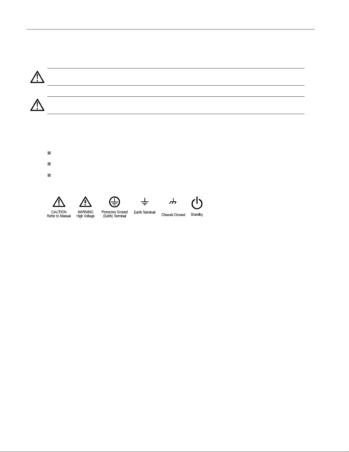
Symbols and Terms on the Product
These terms may appear on the product:
DANGER indicates an injury hazard immediately accessible as you read the marking.
WARNING indicates an injury hazard not immediately accessible as you read the marking.
CAUTION indicates a hazard to property including the product.
The following symbol(s) may appear on the product:
ummary
iv AWG5000 and AWG7000 Series Quick Start User Manual

Compliance Info
rmation
Compliance In
This section lists the EMC (electromagnetic compliance), safety, and environmental standards with which the instrument
complies.
EMC Compliance
EC Declarati
Meets intent of Directive 2004/108/EC for E lectromagnetic Compatibility. Compliance was demonstrated to the following
specifications as listed in the Official Journal of the European Communities:
EN 61326-1 2006. EMC requirements for electrical equipment for measurement, control, and laboratory use.
CISPR 11:2003. Radiated and conducted emissions, Group 1, Class A
IEC 61000-4-2:2001. Electrostatic discharge immunity
IEC 61000-4-3:2002. RF electromagnetic field immunity
IEC 61000-4-4:2004. Electrical fast transient / burst immunity
IEC 61000-4-5:2001. Power line surge immunity
IEC 61000-4-6:2003. Conducted RF immunity
on of Conformity – EMC
formation
123
IEC 61000-4-11:2004. Voltage dips and interruptions immunity
EN 61000-3-2:2006. AC power line harmonic emissions
EN 61000-3-3:1995. Voltage changes, fluctuations, and flicker
ean contact.
Europ
Tektronix UK, Ltd.
Western Peninsula
Western Road
Bracknell, RG12 1RF
United Kingdom
1
2
3
product is intended for use in nonresidential areas only. Use in residential areas may cause electromagnetic interference.
This
Emissions which exceed the levels required by this standard may occur when this equipment is connected to a test object.
To ensure compliance with the EMC standards listed here, high-quality shielded interface cables should be used.
AWG5000 and AWG7000 Series Quick Start U ser Manual v

Compliance Info
rmation
Australia / New Zealand Declaration of Conformity – EMC
Complies with the EMC provision of the Radio communications Act per the following standard, in accordance with ACMA:
CISPR 11:2003. Radiated and Conducted Emissions, Group 1, Class A, in accordance with EN 61326-1:2006.
Safety Compliance
EC Declarati
Compliance w as demonstrated to the following specification as listed in the Official Journal of the European Communities:
Low Voltage Directive 2006/95/EC.
EN 61010-1: 2001. Safety requirements for electrical equipment for measurement control and laboratory use.
on of Conformity – Low Voltage
U.S. Nationally Recognized Testing Laboratory Listing
UL 61010-
1:2004, 2
nd
Edition. Standard for electrical measuring and test equipment.
Canadian Certification
CAN/CSA-C22.2 No. 61010-1:2004. Safety requirements for electrical equipment for measurement, control, and
laboratory use. Part 1.
Additional Compliances
IEC 61010-1: 2001. Safety requirements for electrical equipment for measurement, control, and laboratory use.
ment Type
Equip
Test and measuring equipment.
Safety Class
ss 1 – grounded product.
Cla
Pollution Degree Description
A measure of the contaminants that could occur in the environment around and within a product. Typically the internal
environment inside a product is considered to be the same as the external. Products should be used only in the environment
for which they are rated.
Pollution Degree 1. No pollution or only dry, nonconductive pollution occurs. Products in this category are generally
encapsulated, hermetically sealed, or located in clean rooms.
Pollution Degree 2. Normally only dry, nonconductive pollution occurs. Occasionally a temporary conductivity that is
caused by condensation m ust be expected. This location is a typical office/home environment. Temporary condensation
occurs only when the product is out of service.
vi AWG5000 and AWG7000 Series Quick Start User Manual
Compliance Info
Pollution Degree 3. Conductive pollution, or dry, nonconductive pollution that becomes conductive due to condensation.
These are shelt
sunshine, rain, or direct wind.
Pollution Degree 4. Pollution that generates persistent conductivity through conductive dust, rain, or snow. Typical
outdoor locations.
ered locations where neither temperature nor humidity is controlled. The area is protected from direct
rmation
Pollution De
Pollution Degree 2 (as defined in IEC 61010-1). Note: Rated for indoor use only.
gree
Environmental Considerations
This secti
Product End-of-Life Handling
Observe the following guidelines when recycling an instrument or component:
Equipment recycling. Production of this equipment required the extraction and use of natural resources. The equipment may
contain s ubstances that could be harmful to the environment or human health if improperly handled at the product’s end of life. In
order to avoid release of s uch substances into the environment and to reduce the use of natural resources, we encourage you to
recycle this product in an appropriate syste m that will ensure that most of the materials are reused or recycled appropriately.
Mercury notification. This product uses an LCD backlight lamp that contains mercury. Disposal may be regulated due to
envir
Web page (www.eiae.org) for disposal or recycling information.
1
on provides information about the environmental impact of the product.
This symbol indicates that this product c omplies w ith the applicable European Union requirements according
to Directives 2002/96/EC and 2006/66/EC on waste electrical and electronic equipment (WEE E) and
batteries. For information about recycling options, check the Support/Service section of the Tektronix Web
site (www.tektronix.com).
onmental considerations. Please contact your local authorities or, within the United States, refer to the E-cycling Central
Mercury notification does not apply to AWG5000C or AWG7000C series instruments.
1
Perchlorate materials. This product contains one or more type CR lithium batteries. According to the state
lifornia, CR lithium batteries are classified as perchlorate materials and require special handling. See
of Ca
www.dtsc.ca.gov/hazardouswaste/perchlorate for additional information.
Restriction of Hazardous Substances
This product has been classified as Monitoring and Control equipment, and is outside the scope of the 2002/95/EC RoHS
Directive.
AWG5000 and AWG7000 Series Quick Start User Manual vii

Preface
Preface
This manual describes the installation and operation of AWG5000 and AWG7000 series instruments. Basic operations and
concepts are presented in this manual. For more detailed information, see the online help on your instrument. The following
instruments are supported by this manual:
AWG7000C Series: AWG7122C AWG7082C
AWG5000C Series: AWG5002C, AWG5012C, AWG5014C
AWG7000B Series: AWG7121B, AWG7122B, AWG7061B, AWG7062B
AWG5000B Series: AWG5012B, AWG5014B, AWG5002B, AWG5004B
Key Features
The follow
Microsoft
Microsof
Extended
28-bit di
Interle
Fast seq
A large 1
An intu
Remova
Suppor
LAN (1
Touch
ing list describes some of the key features of the AWG5000 and AWG7000 series instruments:
Windows 7 Professional operating system, AWG5000C and AWG7000C series
t Windows XP Professional operating system, AWG5000B and AWG7000B series
analog output bandwidth (Option 02 and Option 06)
gital data output (Option 03), AWG5002B, AWG5012B, AWG5002C, and AWG5012C only
ave and extended analog output bandwidth (Option 06), AWG7122B, AWG7122C, and AWG7082C only
uence switching (Option 08), AWG5000B series, AWG7000B series, and AWG7000C series only
0.4 inch (264.2 mm) high resolution XGA color display
itive, graphical user interface , with built-in online help
ble hard disk drive (Option 05)
ts USB 2.0 interface
000/100/10 Base-T)
screen user interface
viii AWG5000 and AWG7000 Series Quick Start User Manual

Table i: AWG5000C and AWG7000C features
Model AWG7122C AWG7082C AWG5014C AWG5012C AWG5002C
Maximum
sampling rate
D/A resolution 8 bits or 10 bits (selectable)
Waveform
length
Analog output 2 2 4 2 2
Marker output 4 4 8 4 4
Maximum
analog
amplitude
Maximum
amplitude
and analo
g
bandwidth
Digital data
output
12 GS/s
(24 GS/s by
8 GS/s (16 GS/s
by interleave)
1.2 GS/s 1.2 GS/s 600 MS/s
interleave)
14 bits
32 M or 64 M (Option 01) 16 M or 32 M (Option 01)
2V
(standard model)
pp
1V
(Option 06)
pp
2 Vp-p, 750 MHz (Normal mode)
1 Vp-p, 3.
5 GHz (Direct D/A mode)
2 Vp-p, 250 MHz (Normal mode)
0.6 Vp-p,
4.5 V
pp
370 MHz (Direct D/A mode)
1 Vp-p, 7.5 G Hz (Option 02
or Option 06)
N/A N/A N/A
28 bits
(Option 03)
28 bits
(Option 03)
Preface
Table ii: AWG5000B and AWG7000B features
1B/
AWG501
AWG5014B
Model
Maxim
rate
um sampling
AWG712
1B/
AWG7122B
12 G S /s (24 GS/s by
interleave)
AWG706
AWG7062B
6 GS/s 1.2 GS/s 600 MS/s
D/A resolution 8 bits or 10 bits (selectable)
Waveform length 32 M or 64 M (Option 01) 16 M or 32 M (Option 01)
Analog output 1 or 2 2 or 4
imum analog
Max
amplitude
Maximum amplitude
and analog
ndwidth
ba
arker output
M
1
1 Vp-p, 7.5 GHz (O ption 02 or Option 06)
Digital data output
1
When 10 bits DAC resolution is selected in the AWG7000 series, Marker Output is disabled.
2V
(standard model)
pp
1V
(Option 06)
pp
2 Vp-p, 750 MHz (Normal mode)
p-p, 3.5 GHz (Direct D/A mode)
1V
or 4
2
/A
N
2B/
AWG500
AWG5004B
14 bits
V
4.5
pp
2 Vp-p, 250 MHz (Normal mode)
6 Vp-p, 370 MHz (Direct D/A mode)
0.
or 8
4
8 bits (Option 03)
2
2B/
AWG5000 and AWG7000 Series Quick Start User Manual ix
Preface
Documentation
Review the following table to locate more information about this product.
To read about Use these documents
Installation and operation (overviews) Read the Quick Start User Manual for general information about how to
In-depth operation and user interface help Access the user online help from the Help menu for information on
Programmer commands
Specifications and performance verification
procedures
Service procedures
use your instrument.
virtually all controls and elements on screen. Online help includes detailed
instructions for using instrument functions.
Access the programmer online guide from the Help menu. The
programmer guide includes the syntax of remote commands.
Read the technical reference documents for specifications and the
performance verification procedures. T hese documents are available on
the documentation CD.
Read the service manuals to service instruments to the module
level. The service manuals are available on the Tektronix Web site
(www.tektronix.com/manuals).
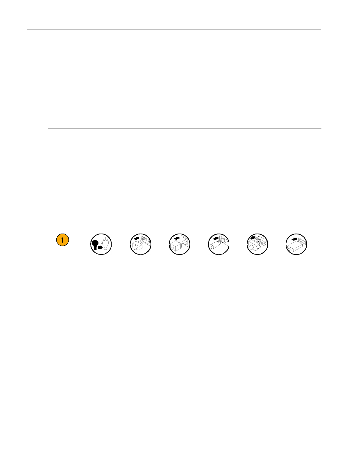
Conventions Used in this Manual
The following icons are used throughout this manual.
Sequence
Step
Front panel
power
Connect
power
Network
PS2 SVGA USB
x AWG5000 and AWG7000 Series Quick Start User Manual

Installing Your Instrument
Unpack the instrument and check that you received all items listed as Standard Accessories. Check the Tektronix Web
site (www.tektronix.com) for the most current information.
NOTE. The instrument does not ship with a product software CD. To reinstall the product software, go to the Tektronix Web
site and download the latest product software for your instrument.
Standard Accessories
Accessory Tektronix part number
AWG5000B and AWG7000B Series Quick Start User Manual
English (Option L0)
Japanese (Option L5)
Simplified Chinese (Option L7)
Traditional Chinese (Option L8)
Russian (Option L10)
Documentation CD
User Online Help (part of the product software)
Programmer Online Help (part of the product software)
Windows compatible keyboard 119-7083-xx
Windows compatible mouse 119-7054-xx
Lead Set for DC Output
Front Protect C over
Accessory Pouch 016-1441-xx
50 Ω SMA Termination, Male, DC to 18 GHz (3 each)
(AWG7000 series only)
Power cord – one of the following:
North America (Option A0)
Universal Euro (Option A1)
United Kingdom (Option A2)
Australia (Option A3)
Switzerland (Option A5)
Japan (Option A6)
China (Option A10)
India (Option A11)
No power cord or AC adapter
(Option A99)
071-2481-xx
071-2482-xx
071-2483-xx
071-2484-xx
020-2971-xx
063-4134-xx
---
---
012-1697-xx
200-4963-xx
015-1022-xx
Installing Your
Instrument
AWG5000 and AWG7000 Series Quick Start U ser Manual 1
Installing Your
Instrument
Operating Requirements
CAUTION. To e n
Place the instrument on a cart or bench, observing clearance requirements:
Top: 20 mm (0.8 in)
Left and right side: 150 mm (5.9 in)
Bottom: 20 mm (0.8 in)
Rear: 75 mm (3 in)
Environmental Req
Before operating the instrument, ensure that the instrument has warmed up for 20 minutes and meets the environmental
requirements lis
Requirement Description
Temperature (op
Relative humid
Altitude (ope
sure proper cooling, keep sides of the instrument clear of obstructions.
uirements
ted in the following table.
erating)
ity (operating)
rating)
10 °C to 40 °C (+50
5% to 95% relati
5% to 45% relative humidity above 30 °C (86 °F) up to
+40 °C (104 °F) noncondensing, and as limited by a
maximum wet-bu
Up to 3,000 m (a
°F to +104 °F)
ve humidity at up to 30 °C (86 °F)
lb temperature of 29 °C (84.2 °F)
pproximately 10,000 feet)
Power Supply Requirements
WARNING. To r
operating voltage range.
Source Voltage and
100 VAC to 240 VAC,
educe the risk of fire and shock, ensure that the mains supply voltage fluctuations do not exceed 10% of the
Frequency
47 Hz to 63 Hz
Power Consumption
Less than 450 W (AW
Less than 560 W (AWG5000 series)
G7000 series)
2 AWG5000 and AWG7000 Series Quick Start User Manual
Cleaning
Installing Your
Instrument
WARNING. To a v
the following procedures.
Inspect the arbitrary waveform generator as often as operating conditions require. To clean the exterior surface, perform
the following steps:
1. Remove loose dust on t
2. Use a soft cloth damp
CAUTION. To avoid damage to the surface of the arbitrary waveform generator, do not use any abrasive or chemical
cleaning agents.
oid personal injury, power off the instrument and disconnect it from line voltage before performing any of
he outside the instrument with a lint-free cloth. Use care to avoid scratching the front panel display.
ened with water to clean the instrument. Use a 75% isopropyl alcohol solution as a cleaner.
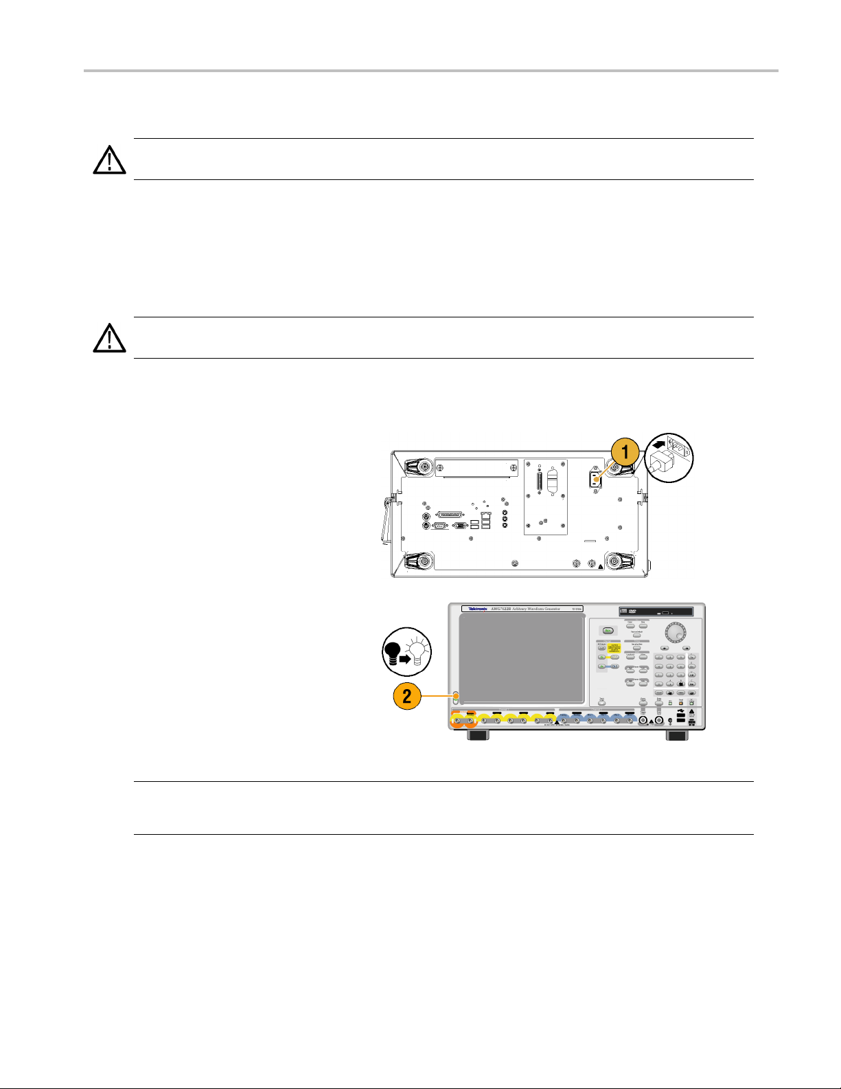
Powering on the Instrument
1. Connect the AC power cord t
the instrument.
o the rear of
2. Use the front-panel po
switch the instrument on.
NOTE. Before using the instrument, create a set of operating system restore discs, to provide a back-up of the system.
The instrument doe
(See page 11, Creating Operating System Restore Discs.)
wer button to
s not ship with operating restore media. Refer to the instructions to create the operating restore discs.
AWG5000 and AWG7000 Series Quick Start U ser Manual 3
Installing Your
Instrument
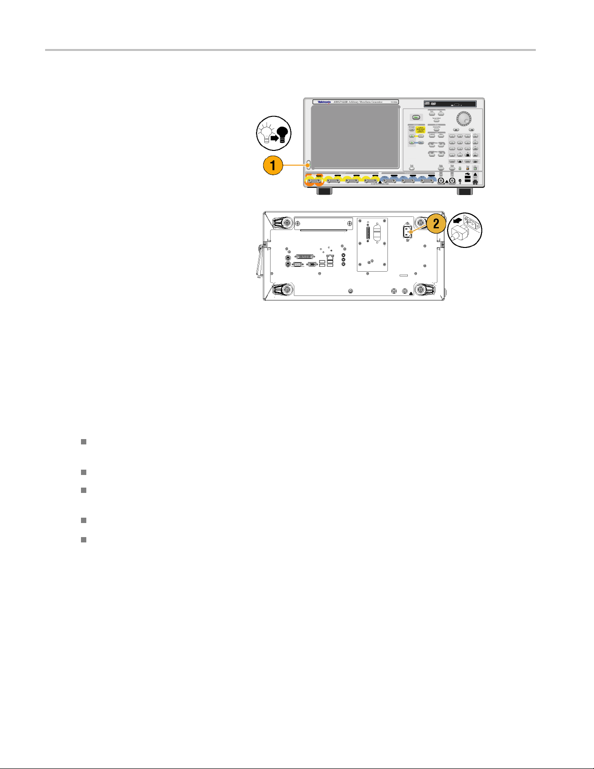
Powering off the Instrument
1. Use the front-
the shutdown process.
Wait approximately 30 seconds for the
instrument t
2. To com p le te
instrument, perform the shutdown just
described, and then remove the power
cord from t
panel power button to start
o power off.
ly remove power to the
he instrument.
Windows Interface Guidelines
Because the instrument uses the Microsoft Windows interface, you have open access to the W indows operating system. You
can access the Windows desktop to load and run other Windows-based applications such as Microsoft Excel, WordPad, and
Paint.
Follow these guidelines to avoid making operating system changes that might cause problems or annoyances while trying to
use the instrument:
Be careful when making changes in the Control Panel. Avoid making changes to any controls with which you are
unfamiliar.
Do not delete or change any system fonts; this can affect the quality of the display.
Do not change the system Display Properties, such as the Background, Appearance, Effects, or S e ttings. Making such
changes can affect the usability of the instrument and the touch screen.
Do not change the contents of the Windows folder or the Program Files\Tektronix\AWG\ System folder.
Do not change the BIOS settings; this can affect the overall operation of the instrument.
If you think that your Windows interface might cause problems with the instrument, contact your local Tektronix support
center for assistance.
4 AWG5000 and AWG7000 Series Quick Start User Manual
Connecting to a Network
You can connect your instrument to a network for printing, file sharing, Internet access, and other functions. Consult with
your network administrator and use the standard Windows utilities to configure the instrument for your network. For setting
GPIB or LAN configuration, use the GP IB/LAN Configuration dialog box from System menu.
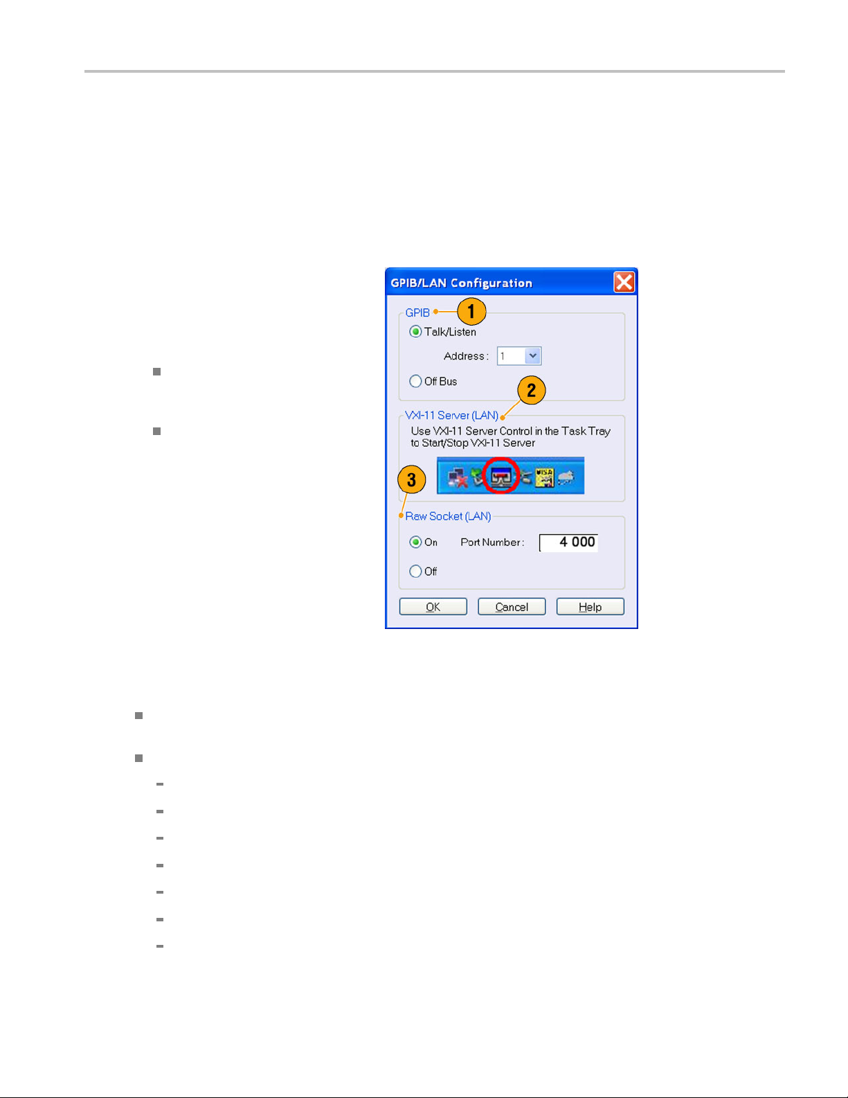
Setting GPIB/LAN
Select System > GPIB/LAN Configuration
to open the GPIB/LAN Configuration dialog
box.
1. Set the instrument GPIB bus
communication:
Talk/Listen – Select this mode to
remotely control the instrument from
an external host computer.
Off Bus – Select this mode to
disconnect the instrument from the
GPIB bus.
Installing Your
Instrument
2. The instrument supports the VXI-11
Server (LAN). Use VXI-11 Server Control
in the Task Tray to Start/Stop VXI-11
Server.
3. TCP/IP protocol is also supported. On
and Off of socket communication are
controlled here. The port number is fixed
to 4000.
Quick Tip
To start the VXI-11 Server automatically at power-on, check the "Start server automatically at system power on " check
box in the VXI-11 Server Control.
The following operations cannot be performed through a GPIB or LAN connection:
Editing a waveform
Changing size or name of waveform
Converting the w aveform format
Importing waveform data from the AWG5000 series and AWG7000 series setup (*.AWG) file
Importing a Tektronix DTG5000 series file (*.DTG)
Importing a Tektronix AWG400/500/600/700 series SEQ file
Exporting waveform data
AWG5000 and AWG7000 Series Quick Start U ser Manual 5
Installing Your
Instrument
Controlling the Instrument Using a R emote PC
You can use your PC to control the arbitrary waveform generator through a LAN using the Windows Remote Desktop
function. If your PC has a larger screen, you can edit waveforms easily using your keyboard and mouse. You can also use a
third party software installed on your PC to create a waveform and import it through a network.
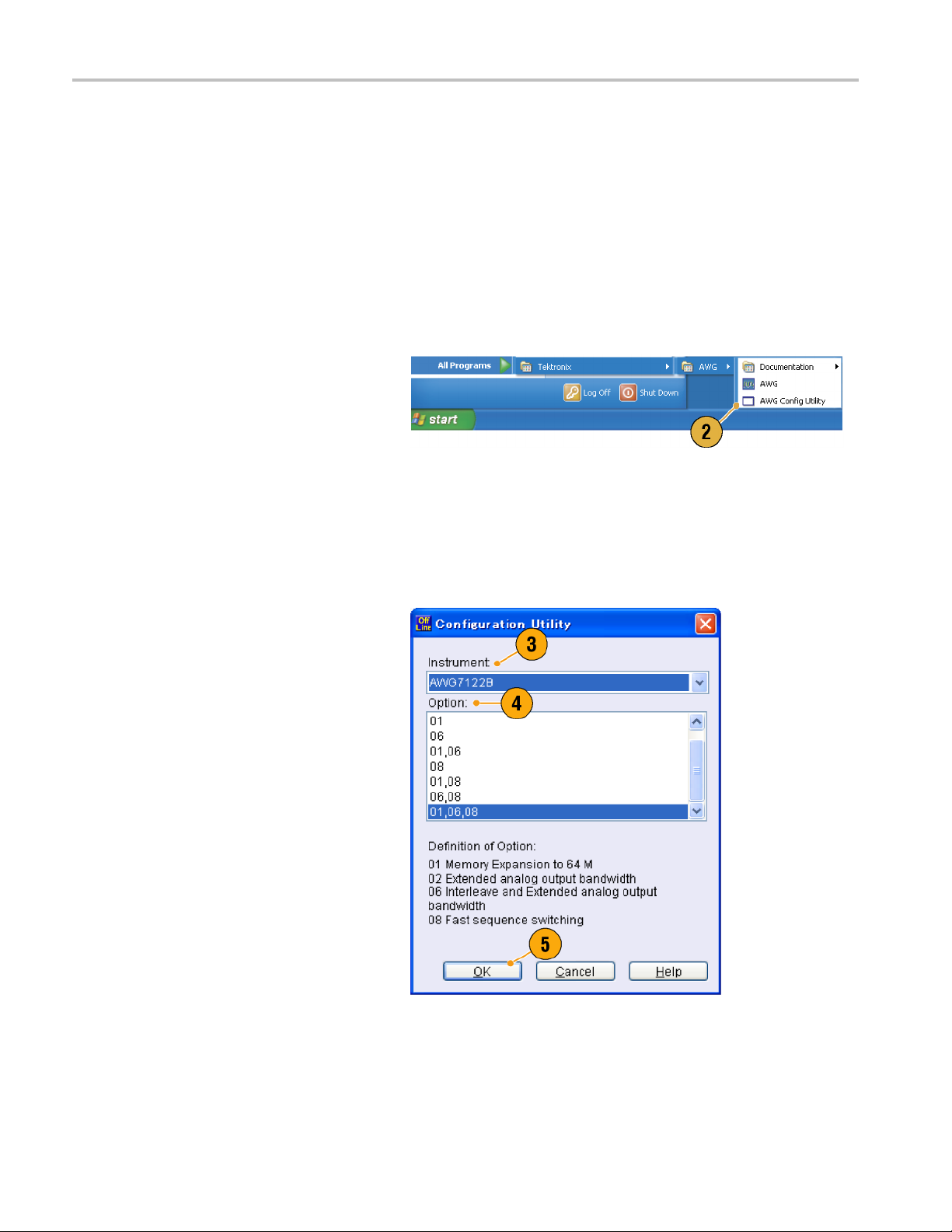
Offline Mode
The Offline Mode is a function that you can use to run the instrument application on your PC. Install the application on your
PC; the instrument hardware is not required. You can create and edit the instrument setups. The setup files that you create
can be used l
1. Go to the Tektronix Web site
(www.tektronix.com/software) and
download t
Product Software. Follow the instructions
to install the AWG application on your
PC.
ater with your arbitrary waveform generator.
he latest version of the AWG
2. Before us
set up the instrument con figuration.
From the Windows Start menu, select All
Program
Utility.TheConfiguration Utility dialog
box appears.
3. Select your instrument type.
4. Select your instrument option
configu
5. Click
Run the instrument application from the
Start menu. The setup configuration you
have m
will be reflected in the application.
ing the offline mode, you must
s > Tektronix > AWG > Config
ration.
OK.
ade using the Configuration Utility
6 AWG5000 and AWG7000 Series Quick Start User Manual
Inspecting Your Instrument
Two types of diagnostics are provided to verify the functionality of your instrument:
Power-on self test – Every time you power on the instrument, the instrument automatically performs the internal
diagnostics.
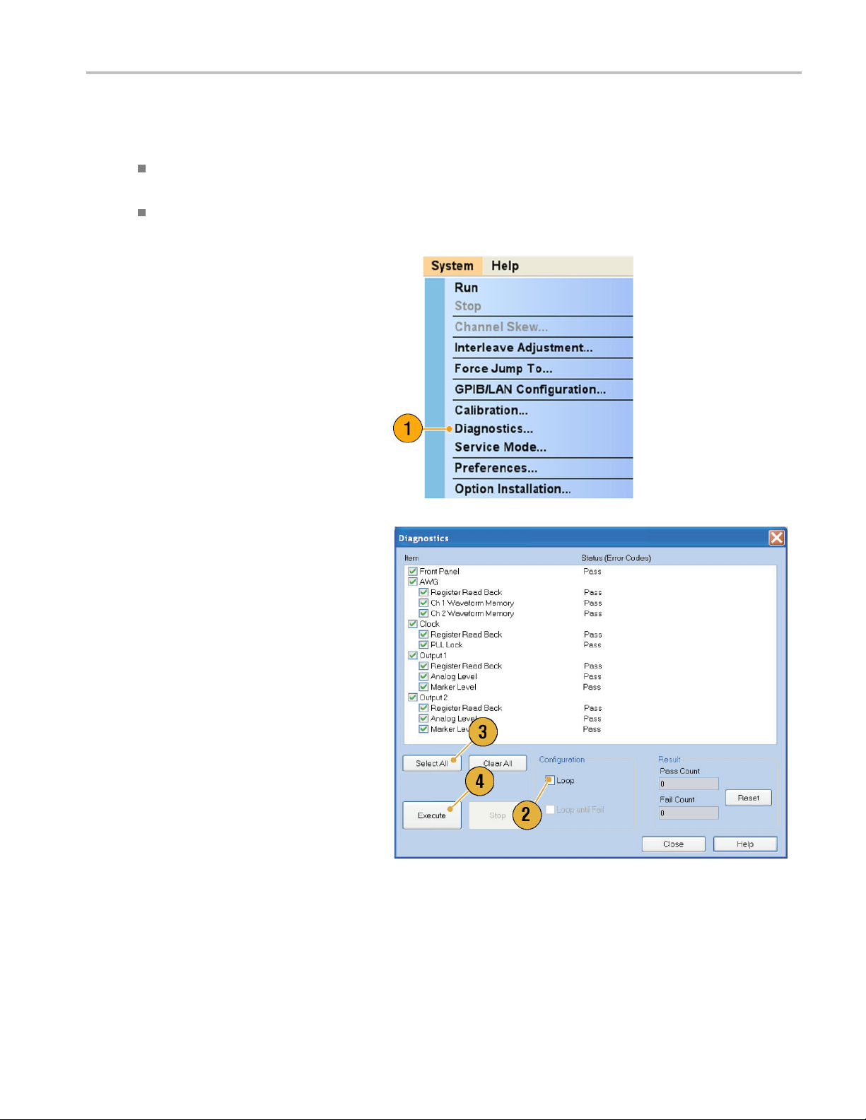
Diagnostics from the System menu – You can also run the internal diagnostics using the System menu. Use the
following procedures:
1. Select System > Diagnostics from the
menu bar.
The Diagnostics dialog box appears.
Installing Your
Instrument
2. Confirm that the Loop box is not
checked.
If Loop is checked, the diagnostics runs
until it is manually stopped.
3. If you click Select All, all diagnostic
items are checked.
You can execute all items together or you
can execute only the selected item(s).
4. Click Execute to start the diagnostics.
Verify that the instrument passes all
tests. If diagnostic failures occur, contact
your local Tektronix service personnel.
AWG5000 and AWG7000 Series Quick Start U ser Manual 7
Installing Your
Instrument
Self Calibration
The self calibration uses internal calibration routines that check electrical characteristics such as analog level and marker
level, and then adjust the internal calibration constants as necessary. Marker level is checked only in the AWG7000 series
instruments.
NOTE. Power on the instrument and allow a 20 minute warm-up period before performing this procedure.
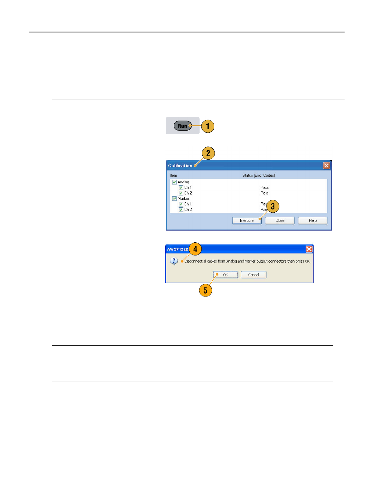
1. Confirm that there is no output signal by
verifying that the front-panel Run button
indicator is off.
2. To perform the calibration suite, select
System > Calibration from the menu
bar.
The Calibration dialog box appears.
3. Select Execute.
4. A pop-u
5. Remove the cables and then select OK.
NOTE. Self calibration is not valid until the instrument reaches a valid temperature. (See page 2, Operating Requirements.)
NOTE. If your instrument is an AWG7000 series, perform self ca libration once a month to maintain the analog and marker
put level accuracy. Failure to do so can prevent the instrument from meeting warranted performance levels for analog
out
and marker output.
If your instrument is an AWG5000 series, perform self calibration once a year to maintain the analog output level accuracy.
p message asks you to remove
all the cables from output connectors.
Wait until the calibration completes.
calibration items, the Status
For all
control should indicate Pass. If it does
not, contact your local Tektronix service
nnel.
perso
8 AWG5000 and AWG7000 Series Quick Start User Manual
Preventing Instrument Damage
Overheat Protection
The internal instrument temperature is monitored and the instrument is protected against overheating damage by the
following actions:
A warning message will appear if the internal temperature reaches the first threshold level.
The instrument will shut down if its temperature reaches the second threshold level.
If the warning message appears or the instrument shuts down, check for the following conditions. (See page 2, Operating
Requiremen
ts.)
Installing Your
Instrument
The ambient
The requir
The instru
temperature requirement is not being met.
ed cooling clearance is not being met.
ment fan is not working properly.
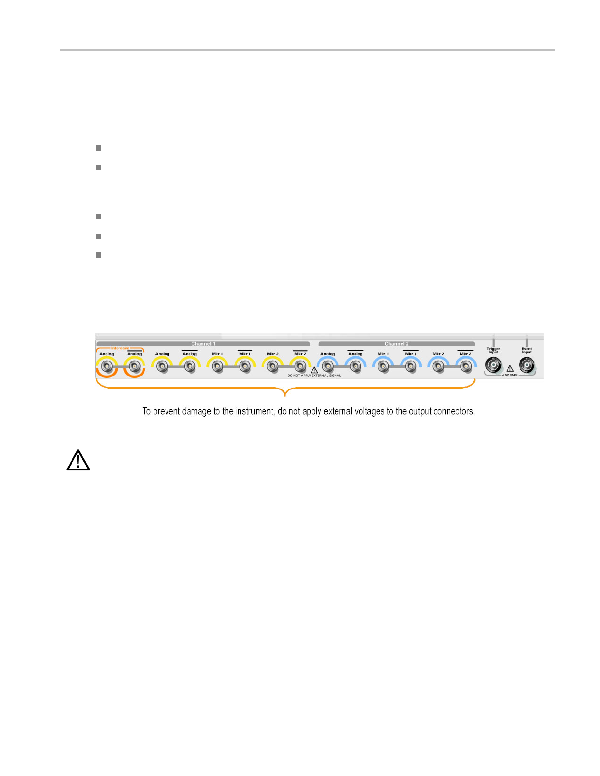
Output Connectors
The arbitrary waveform generator has both output and input connectors on the front panel. Do not apply external voltage
to the output connectors.
CAUTION. Always turn off the signal outputs when you connect or disconnect cables to/from the signal outputs connectors.
If you connect a DUT while the instrument signal outputs are in the On state, it may cause damage to the instrument or DUT.
AWG5000 and AWG7000 Series Quick Start U ser Manual 9
Installing Your
Instrument
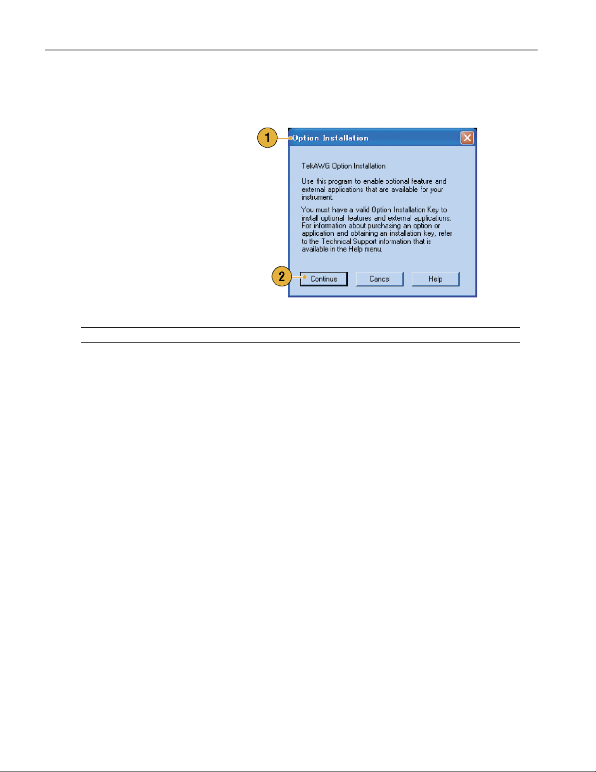
Option Installation
Use the Option Installation dialog box to enable the upgrades that you purchased from Tektronix for your instrument. For the
most current list of upgrades, go to www.tektronix.com or contact your local Tektronix representative.
1. Select System > Option Installation to
open the Option Installation dialog box.
2. Click Continue to open the second
dialog box.
Enter the Option Installation Key
provided by Tektronix, and follow the
on-screen instructions to install the
option.
NOTE. After entering the option key, you must restart the instrument application to activate the option.
10 AWG5000 and AWG7000 Series Quick Start User Manual
Creating Operat
ing System Restore Discs
Creating Oper
The instrument does not ship with an operating system restore disc. Use the following procedure to create a set of discs that
enable you to restore the operating system if the need arises.
CAUTION. Restoring the operating system reformats the hard disk d rive. User data, including the ISO images, will be lost
(the Acronis Recovery partition and the related data are not destroyed). To avoid complications, create the operating system
restore discs before attempting to restore the operating system.
NOTE. This procedure creates a set of restore discs for the Microsoft Windows operating system. After restoring the
operating s ystem, reinstall the instrument application software. Go to the Tektronix Web site (www.tektronix.com/software) to
download the product software, and follow the instructions to reinstall the instrument application software.
ating System Restore Discs
Creating Restore Discs
Prerequi
sites.
A separa
USB flash
DVD burner.
Blank DVD-R (NOT DVD-R/W) discs (about 2; the exact number depends on the number of backup files).
You will need:
te PC with a DVD±R/W drive and DVD burning software.
drive (8 GB or larger) or a local area network to transfer ISO image files from the instrument to the PC with
To create a set of restore discs:
1. On the instrument, navigate to C:\backup.
2. Using the USB flash drive (or through your LAN), transfer each of the files labeled restoreN.iso to the PC w ith the
DVD burner.
3. Using the DVD burning software, burn each of the backup ISO image files (restore1.iso to restoreN.iso) to a disc. Label
f the discs with the backup file name, instrument name, instrument serial number, and date.
each o
4. After
5. Store the backup discs as defined by your company policy.
NOT
toring the Instrument Operating System
Res
You can restore the instrument operating system from either a file on the instrument hard disk drive, or from the set of
instrument restore discs. (See page 11, Creating R estore Discs.)
CAUTION. Restoring the operating system reformats the hard disk drive. User data, including the ISO images w ill be lost
(the Acronis Recovery partition and the related data are not destroyed).
you have burned the OS restore discs, also place copies of the disk image files (*.iso) in a network location, on a
separate hard disk, or on optical media for backup purposes. (If you ever restore the instrument OS, the ISO images
on the instrument hard disk will be erased.)
E. You can use restore discs only on the instrument with which they were created.
AWG5000 and AWG7000 Series Quick Start U ser Manual 11

Creating Operat
Restoring the Operating System from the Restore Discs
ing System Restore Discs
NOTE. This pro
NOTE. You can use restore discs only on the in strument with which they were created.
1. Insert restore disc 1 in the instrument DVD drive.
2. Restart the instrument. The restore software opens automatically if the DV D drive is the first bootable device. If the
DVD drive is
from the discs.
3. Click Restore.
4. In the Confirmation dialog box, c lick Yes to restore the operating system, or No to exit the restore process.
5. When prompted, remove the current restore disc and insert the requested disc. Continue until the restore process
is complete.
NOTE. The
long as the disc drive light continues to blink.
NOTE. At the beginning and end of the recovery session, the recovery application will request you to repeatedly provide the
d last discs in the set. This is normal behavior for the recovery application.
first an
cedure requires that the DVD drive is set as the first boot device (this is the default setting).
not the first bootable device, you must enable it as the first bootable device before performing a restore
progress bar might not move during parts of the restore process. However, the restore process is working as
6. When the restore process is completed, remove the last restore disc and restart the instrument.
7. Install the AWG application software. If you have not already done so, go to the Tektronix Web site to download the
software (www.tektronix.com/software) and follow the instructions to install the software for your instrument.
oring the Operating System from the Instrument Hard Disk
Rest
The instrument contains an operating system restore file on a separate partition of the hard drive.
1. Restart the instrument. During the boot-up process you will see the following message at the top of the screen:
Starting Acronis Loader… press F5 for Acronis Startup Recovery Manager
2. Repeatedly press the F5 key until the Acronis True Image Tool opens. There is a five-second time period from when the
message appears until the instrument proceeds with the normal instrument startup. If the instrument does not open the
Acronis application, power off the instrument, then power on the instrument and try again.
3. Click Restore.
4. In the Confirmation dialog box, click Yes to restore the instrument operating system, or No to exit the restore process.
The restore process takes approximately 10 minutes; the actual time depends on the instrument configuration.
5. Install the AWG application software. If you have not already done so, go to the Tektronix Web site to download the
software (www.tektronix.com/software) and follow the instructions to install the software for your instrument.
12 AWG5000 and AWG7000 Series Quick Start User Manual
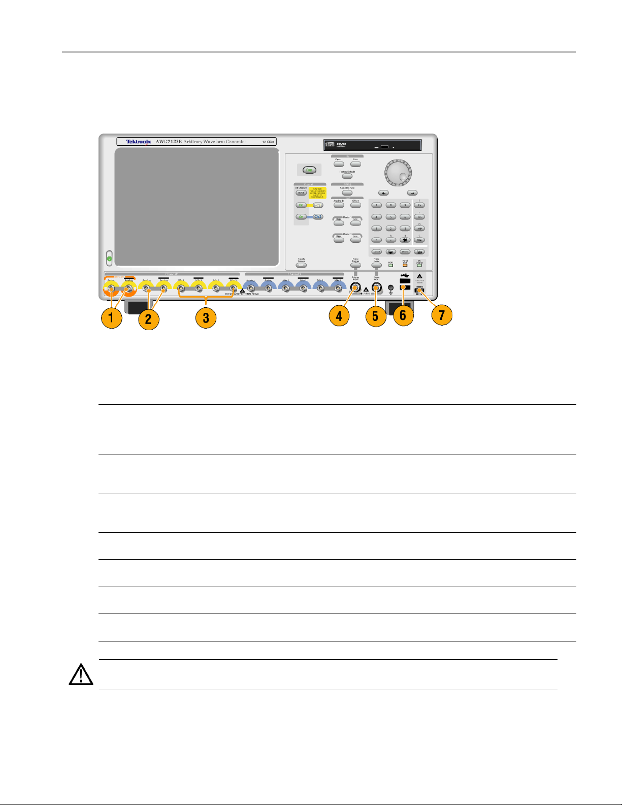
Front Panel
The following figure shows the front panel of an AWG7000 series instrument; AWG5000 series instruments are similar.
Front Panel
Front Panel Connectors
Connector Description
1. Interleave Output The interleave connectors supply analog signals with 12 GS/s through
24 GS/s range (AWG7000C series Option 06 and AWG7122B Option 06
only). The AWG7082C Option 06 range is from 8 GS/s to 16 GS/s.
Connector type: SMA
2. Analog Output
3. Marker Output
4. Trigger Input External trigger signal is applied to this connector.
5. Event Input Event signal is applied to this connector.
6. USB Two USB connectors are present on the front panel.
7. DC Output This connector supplies four channel DC voltage.
CAUTION. Always turn off the signal outputs when you connect or disconnect cables to/from the signal outputs connectors.
If you connect a DUT while the instrument signal outputs are in the On state, it might cause damage to the instrument or DUT.
These connectors supply analog signals.
Connector type: SMA (AWG7000 series)
Connector type: BNC (AWG5000 series)
These connectors supply marker signals.
Connector type: SMA (AWG7000 series)
Connector type: BNC (AWG5000 series)
Connector type: BNC
Connector type: BNC
Connect a USB device.
Connector type: 2.54 mm 2 x 4 pin header (female)
AWG5000 and AWG7000 Series Quick Start U ser Manual 13
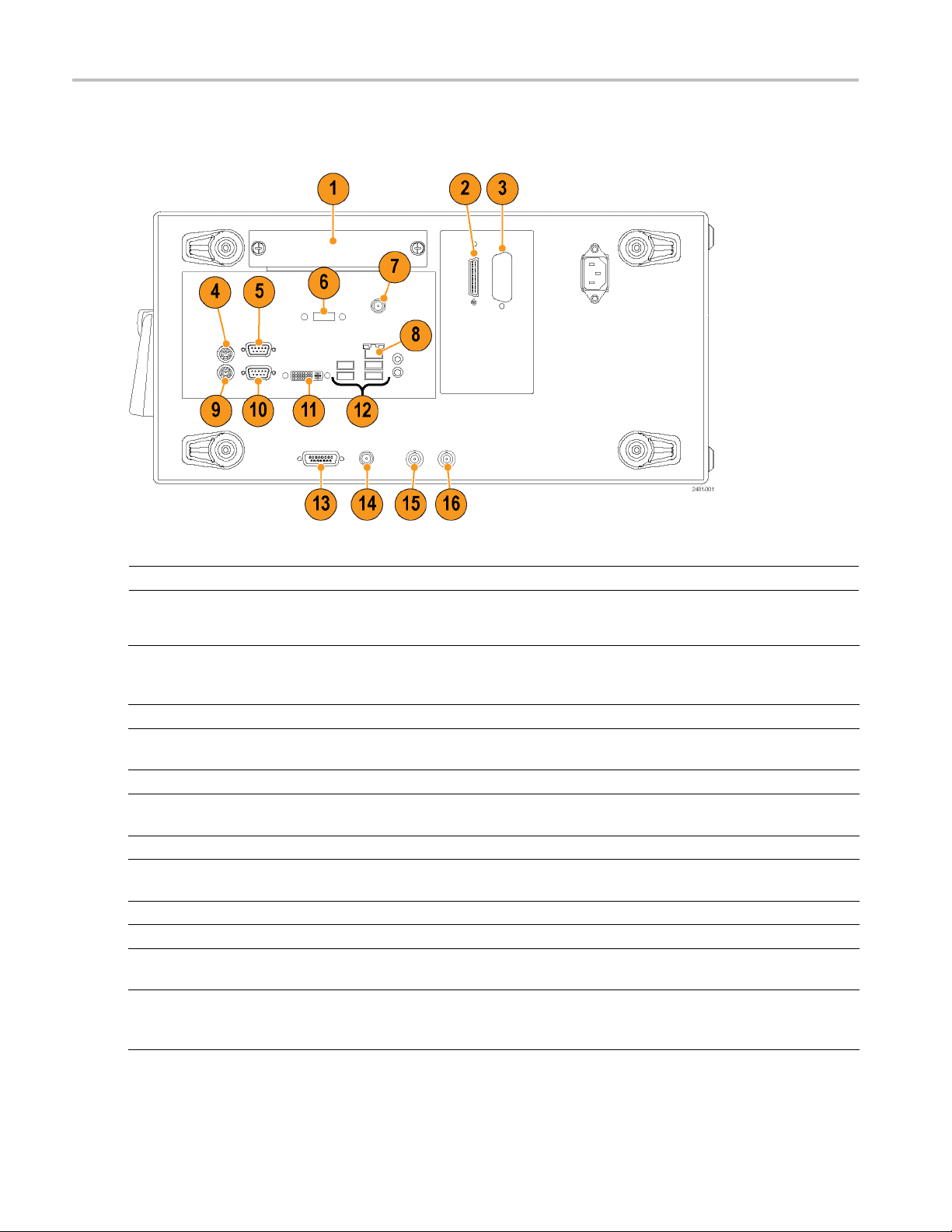
Rear Panel (AWG7
000C Series)
Rear Panel (AW
NOTE. AWG7000B series have a similar connectors in different locations.
G7000C Series)
Connector Description
1. Removable HDD
2. Tek L i nk
3. GPIB Use the GPIB connector to connect the instrument to a GPIB controller
4. PS-2 Mouse connector Use the PS-2 connector to connect a mouse to the instrument.
5. COM2 Use the COM2 serial port to c onnect to other devices through the serial
6. eSATA port Use the eSATA port to connect external SATA devices to the instrument.
7. Synchronization Clock Out port Use the Synchronization Clock Out port to provide a synchronization signal
8. LAN Use the RJ-45 connector to connect the instrument to a network.
9. PS-2 Keyboard connector Use the PS-2 connector to connect a PS-2 keyboard to the instrument.
10. COM1 Use the COM1 serial port to connect to other devices through the serial
11. Video
Removable hard disk drive to secure data. If you remove the HDD, user
information such as setup files or waveform data does not remain within
the instrument.
Use the TekLink connector for data import.
for GPIB operation.
port.
to other external devices. Terminate this connector when not in use.
port.
Use the DVI-I Video port to connect a monitor for extended desktop
operation. To connect a VG A monitor to the DVI-I connector, use a
VGA-to-DVI adapter.
14 AWG5000 and AWG7000 Series Quick Start User Manual
 Loading...