

Page 1

xx
AWG4162
ZZZ
Arbitrary Waveform Generator
Printable Help
*P077118900*
077-1189-00
Page 2

Page 3

AWG4162
Arbitrary Waveform Generator
ZZZ
Printable Help
w.tek.com
ww
077-1189-00
Page 4

Copyright © Tektronix. All rights reserved. Licensed software products are owned by Tektronix or its
subsidiaries or suppliers, and are protected by national copyright laws and international treaty provisions.
Tektronix products are covered by U.S. and foreign patents, issued and pending. Information in this publication
supersedes that in all previously published material. Specifications and price change privileges reserved.
TEKTRONIX and TEK are registered trademarks of Tektronix, Inc.
Microsoft, Windows, Windows XP Professional, and Windows 7 are registered trademarks of Microsoft
Corporation.
MATLAB is a registered trademark of The Mathworks, Inc.
Compiled Help part number: 076-0387-00
Contacting Tektronix
Tektronix, Inc.
14150 SW Karl Braun Drive
P.O. Box 500
Beaverton, OR 97077
USA
For product information, sales, service, and technical support:
In North America, call 1-800-833-9200.
Worldwide, visit www.tek.com to find contacts in your area.
Page 5

AWG4162 Basic Application Help Document
Table of Contents
i
Table of Contents
Preface
Documentation ............................................................................................................................................... 1
Getting Started
General Features ............................................................................................................................................ 2
Operating Requirements ................................................................................................................................. 3
Standard Accessories. .................................................................................................................................... 4
Recommended Accessories ............................................................................................................................ 4
Power the Instrument On and Off .................................................................................................................. 5
Protect Your Instrument from Misuse ............................................................................................................ 5
Obtaining the Latest Application and Version Releases ................................................................................ 6
Remote Control ........................................................................................................................................... 11
Overheat Protection ..................................................................................................................................... 14
Table of Contents
Getting Acquainted with Your Instrument
Front Panel .................................................................................................................................................. 15
Rear Panel ................................................................................................................................................... 15
Basic Application Overview
Introduction to Basic Mode ......................................................................................................................... 16
Instrument Control ...................................................................................................................................... 17
Analysis and connectivity Support .............................................................................................................. 17
How to Start Basic Mode ............................................................................................................................ 17
Perform Instrument Self Calibration and Self Diagnostic ........................................................................... 18
Protect Your DUT from Damage ................................................................................................................ 22
Load Impedance, VOCM and the Output Window ..................................................................................... 24
Operating Basics
Default Setup .............................................................................................................................................. 25
Quick tutorial: How to select a waveform and adjust parameters ................................................................... 25
Quick tutorial: How to generate a sine waveform ....................................................................................... 26
Generate a Continuous Waveform .............................................................................................................. 27
Generate a Pulse Waveform ........................................................................................................................ 27
Generate an Arbitrary Waveform ................................................................................................................ 30
Generate Noise and DC ............................................................................................................................... 32
Generate a Burst Waveform .......................................................................................................................... 33
Sweep a Waveform ..................................................................................................................................... 36
Modulate a Waveform ................................................................................................................................. 38
Page 6

ii
AWG4162 Basic Application Help Document
Marker Out .................................................................................................................................................. 43
Adjusting Parameters of Two Channel Signals .......................................................................................... 46
Set up Load Impedance ............................................................................................................................... 49
Set up VOCM ............................................................................................................................................. 50
Invert Waveform Polarity ........................................................................................................................... 50
Add Noise ................................................................................................................................................... 51
Reference Clock Input ................................................................................................................................. 53
Utility Menu ................................................................................................................................................ 54
Save/Recall a Custom Setup ....................................................................................................................... 56
Save a Screen Image ................................................................................................................................... 59
Erase Custom Waveform Files ................................................................................................................... 60
ArbBuilder .................................................................................................................................................. 61
Appendix ..................................................................................................................................................... 80
Page 7

Documentation
Preface
1
AWG4162 Basic Application Help Document
Preface
Item
Purpose
Location
Compliance and Safety
Instructions
Compliance, safety, and basic
installation information
Printed and shipped with
your instrument
Advanced Application
Help
Advanced Application operating
information
On instrument and
available as a PDF
Basic Application Help
Basic Application operating
information
On instrument and
available as a PDF
Programmer Manual
Programming syntax and command
information for remotely controlling
the instrument
Available as a PDF
Service Manual
Instrument servicing procedures and
replaceable parts list
Available as a PDF
Specifications and
Performance Verification
Technical Reference
Instrument specifications and
performance verification procedures
Available as a PDF
Declassification and
Security Instructions
Describes how to sanitize, secure, and
declassify the instrument
Available as a PDF
Your Tektronix AWG4162 Arbitrary Waveform Generator is a convergent waveform generator with full
function AFG (Basic) and AWG (Advanced) modes. Basic mode supports basic arbitrary and function
waveform generation. Advanced mode has an adjustable sampling rate and supports both DDS mode and
arbitrary mode generation, each of which supports sequence, continuous, gated, and trigger modes.
This document describes the Basic Application mode operation.
Documentation
The following table lists related documentation available for your AWG4162. The documentation is
available on the Tektronix Web site (www.tek.com/manuals).
Page 8

General Features
Getting Started
AWG4162 Basic Application Help Document
2
Getting Started
General Features
Two working modes
o Basic (DDS) mode
Two analog channels
600 MHz sine waveforms
2.5 GS/s, 14-bit, 16 kpts arbitrary waveforms
Amplitude up to 5 Vp-p into 50 Ω load
o Advanced (Arbitrary) mode
Two analog channels
16/32-bit digital channels (optional)
1/16/32/64 Mpts per channel arbitrary waveform memory (optional)
Up to 750 MHz bandwidth
SFDR < -60 dBc
Variable sampling rate range from 100 S/s to 2.5 GS/s, with 14-bit vertical resolution, ensures signal
integrity in all aspects
Designed for 100% user-conducted upgrades and configurations, all options activated through SW key
o Optional and upgradable arbitrary waveform memory up to 64 Mpts for each analog channel and
32 Mbit for each digital channel for long waveforms
o Optional 16-32 channel digital outputs. Purchasing SW option includes the shipment of digital
probe accessory.
Dual analog channels and up to 32-bit digital channels, ideal for mixed signal circuit designs
Sync-in and Sync-out interfaces enables the synchronization of multiple units in a daisy chain, to
extend the number of output channels
Digital outputs provide up to 1.25 Gb/s data rate creates high speed digital pattern in parallel
One marker out for each analog channel for triggering and synchronization
Three software-configurable output paths fit all test cases
o Direct DAC mode: 750 MHz bandwidth with differential output
o AC coupled mode: 750 MHz bandwidth with single ended output for RF applications
o Amplified mode: 5 Vp-p amplitude 400 MHz bandwidth with differential output
Full functional sequence with up to 16384 user defined waveforms provides the possibility of
generating complex signals with the best memory usage, in the form of loops, jumps, and conditional
branches
Channel 1 and 2 (together with the corresponding digital output channels) can work independently on
different sampling clocks and sequences
Direct communication with RFXpress® for easy waveform generation in RF applications
Windows based platform with 10.1-in touch screen, front panel buttons, keyboard, and mouse
Compact form factor, convenient for bench top and portability Removable hard disk guarantees the
security of confidential data
USB 3.0 and LAN interfaces for remote control
Page 9

Operating Requirements
Getting Started
3
AWG4162 Basic Application Help Document
Operating Requirements
Source Voltage and Frequency
100 to 240 V RMS@ 50-60Hz
115VRMS@400Hz
Characteristic
condition
Min.
Nom.
Max.
Units
Voltage
Amplitude
45-66Hertz
85
100-240
264
VRMS
360-440 Hertz
100
115
132
VRMS
Voltage Wave
shape
All
Sine
Power Consumption
Maximum: 150W
Measured: 125W
Surge Current
30 A peak (25°C) for 5 line cycles, after product has been
turned off for at least 30 s.
Net Weight
14.2lbs (6.5 kg)
Net Weight with Package
25.2lbs (11.5kg)
Overall Dimensions
Height: 233 mm
Width: 439 mm
Depth: 199 mm
Dimensions with Package
Height: 498 mm
Width: 457 mm
Depth: 574 mm
Clearance
The clearance requirement for adequate cooling is 2.0 in
(50.8mm) on the left side (when looking at the front of the
instrument) and on the rear of the instrument.
Temperature
Operating +5 °C to +50 °C (+41 °F to 122 °F)
Non-operating -20 °C to +60 °C (-4 °F to 140 °F)
Humidity
Operating 8% to 90% relative humidity with a maximum wet
bulb temperature of 29 °C at or below +50 °C, non-condensing
Non-operating 5% to 98% relative humidity with a maximum
wet bulb temperature of 40 °C at or below +60 °C, noncondensing
Altitude
Operating 3,000 m (9,843 feet)
Non-operating 12,000 m (39,370 feet)
Power Supply
Mechanical Characteristics
Environmental Characteristics
Page 10

Standard Accessories
Getting Started
AWG4162 Basic Application Help Document
4
Standard Accessories
Item
Description
TPN
COMPLIANCE AND SAFETY
INSTRUCTIONS
071345100
Document CD with Browser Including the
PDF files of Specs & PV Tech Ref, user
manual, programmer, service manual.
063457000
Application S/W and Instructions
063376310
-
-
174440100
For touch panel
119610700
-
200513000
-
016202900
Male, DC-18GHz; 1 ea / channel
136716200
-
001138701
-
Item
Description
TPN
Pin Header SMA Cable
45 inch
174619300
RMD5000
- Rack mount kit
- Instruction sheet (English)
RMD5000
Manual
Service (English)
Specs & PV Tech Ref
Programmer manual
077-1199-00
077-1197-00
077-1198-00
AWG4HDDE
- Hard disk drive
AWG4HDDE
SMA terminator
50 Ω
136716200
AWG4SYNC
Sync cable; Used for multiple instruments
synchronization
AWG4SYNC
RFX100
RFXpress software
RFX100
AWG4DIG16LVDS
16-bit digital output cable; Used for LVDS
AWG4DIG16LVDS
AWG4DIGSCKT
Digital output connector; AWG4k Digital
Channel Connector on DUT (Amphenol,
U65-B12-40E0C)
AWG4DIGSCKT
TEK-USB-488
GPIB to USB adaptor
TEK-USB-488
HCTEK54
Hard transit case
HCTEK54
Recommended Accessories
Page 11

Power the Instrument On and Off
Getting Started
AWG4162 Basic Application Help Document
5
Power the Instrument On and Off
Power On
Insert the AC power cord into the power receptacle on the rear panel.
Use the front-panel power button to power on the instrument.
Wait until the system shows windows desktop.
You have two selections to open the applications:
You can press or button on front panel to launch one application. You can also click
the shortcut icon or on desktop to launch any one of them.
NOTE. Only one application can be launched at a time. If you want to launch the other application, first
close the one in use.
Power Off
Close the application in use.
Press the front-panel power button to power off the instrument.
You can also use the Windows menu to shut down the instrument.
Protect Your Instrument from Misuse
Check Input and Output Connectors
When connecting a cable, be sure to distinguish the input connector from the output connectors to avoid
making the wrong connection.
Page 12

Obtaining the Latest Application and Version Releases
Getting Started
6
AWG4162 Basic Application Help Document
The instrument has both input and output connectors on the front panel. When connecting a cable, be sure
to distinguish the input connectors from the output connectors.
CAUTION. Do not short output pins or apply external voltages to Output connectors. The instrument
may be damaged.
CAUTION. Do not apply excessive inputs over +10 V to Trigger Input connector. The instrument may be
damaged.
CAUTION. For differential analog output when one connector is used as single-ended output, another
connector should be terminated with a 50 Ω terminator.
Obtaining the Latest Application and Version Releases
The latest version of an optional application that you ordered with your instrument may not be installed
on your instrument. The following download location is a fast and easy way to get the latest software
version.
To download the latest version of software, go to the home page of the Tektronix Web site
(www.tek.com), and locate the Downloads section on that page. Enter the application name in the Search
text box, and select Software in the Select Download Type pull-down menu.
To define the search criteria, use the title of the application in the Search text box. For example, use the
keyword AWG4162 to search for and download the latest version of AWG4162 software.
Install Basic APP
If your instrument has already installed another version of Basic APP, you must first uninstall it. You can
find uninstall details in the “Uninstall Basic APP” section.
1.
Download Basic APP setup package from Tektronix website and decompress it to instrument’s local
disk.
Page 13

Install Basic APP
Getting Started
AWG4162 Basic Application Help Document
7
2.
Double click setup.exe to start the install. When you see the welcome page click Next.
3.
Select accept on the License Agreement page and then click Next.
Page 14

Install Basic APP
Getting Started
AWG4162 Basic Application Help Document
8
4.
Press Install to start installation.
5.
Installation will begin and the instrument will show installation progress.
Page 15

Uninstall Basic APP
Getting Started
AWG4162 Basic Application Help Document
9
6. When “Installation Complete” appears, press Finish to restart the instrument.
Uninstall Basic APP
You can use Basic APP setup package to uninstall the Basic App in following steps.
1. Download Basic APP setup package and decompress to instrument’s local disk.
2. Double click setup.exe. The welcome dialog notices you to remove installed version Basic. Select
“Yes” to start uninstallation.
Page 16

Uninstall Basic APP
Getting Started
AWG4162 Basic Application Help Document
10
3. Uninstallation begins, instrument shows progress and exit automatically.
Besides using setup package, you can also use Windows Control Panel tool to do Basic APP uninstallation
by followed steps:
1. Enter uninstall page through path: Start Control Panel Uninstall a program
Page 17

AWG4162 Basic Application Help Document
11
Remote Control
Getting Started
2. In Uninstall or change a program page, please select “AWG4000 Basic” program, and uninstall it.
3. Wait until uninstall is finished.
Remote Control
You can connect your instrument to a network for printing, file sharing, and Internet access, among other
functions. Consult with your network administrator and use the standard Windows utilities to configure the
instrument for your network. For LAN configuration, use the LAN Configuration dialog box from control
panel.
The instrument can be controlled using VXI-11 (LAN) or USBTMC protocols. It allows you to control the
instrument remotely by using SCPI commands. Please refer to the AWG4162 programmer manual for a
complete description about all available commands. You can follow the next steps to communicate with
your AWG4162 instrument:
1. Connect your LAN cable or USB to the instrument.
2. On the Client-PC (IP Address)or AWG4162(LocalHost), launch the Tek OpenChoice Instrument
Manager window.
Page 18

AWG4162 Basic Application Help Document
12
Remote Control
Getting Started
3. Press Search Criteria… button and enable LAN and USB. Input IP Address if on Client-
PC or LocalHost if on AWG4162 into Hostname, then press Search for searching optionally. You can
also enable Auto Discovery for searching all the available instruments connected in LAN. Then press
Done.
4. Check the Instruments list to verify if the AWG4162 has been correctly detected.
5. Press the Start Application or Utility button to open OpenChoice Talker Listener and
send a *IDN? Command.
Page 19

Remote Control
Getting Started
AWG4162 Basic Application Help Document
13
6. The instrument should respond like this:
TEKTRONIX,AWG4162Basic,C0000012,SCPI:99.0,FV:1.0, where C0000012 is the serial number
and FV:1.0 is the Application version.
7. You can also load an exist script to run in TekVISA. Please see TekVISA Talk/Listener help for more
details.
Page 20

Overheat Protection
Getting Started
AWG4162 Basic Application Help Document
14
Overheat Protection
The instrument internal temperature is monitored in AWG4162. A warning message will appear if the
internal temperature reaches a threshold level, and the instrument will automatically power off.
If the warning message appears, check for following conditions:
The ambient temperature requirement is being met.
The required cooling clearance is being met.
The instrument fan is working properly.
Page 21

Front Panel
Getting Acquainted with Your Instrument
15
AWG4162 Basic Application Help Document
Getting Acquainted with Your Instrument
Front Panel
Rear Panel
Page 22

Basic Application Overview
Introduction to Basic Mode
AWG4162 Basic Application Help Document
16
Basic Application Overview
Introduction to Basic Mode
Running the AWG4162 in Basic mode allows you to easily generate function, pulse, and arbitrary
waveforms. Select from 12 standard waveforms (Sine, Square, Ramp, Pulse, Sin(x)/x, Noise, DC,
Gaussian, Lorentz, Exponential Rise, Exponential Decay, and Haversine). You can also create and save
custom setups, define your own arbitrary waveforms, and create modulated waveforms. The following
table shows the combination of modulation type and the shape of the output waveform.
Run mode
Sine, Square,
Ramp, Arb, Sin(x)/x,
Gaussian, Lorentz,
Exponential Rise,
Exponential Decay,
Haversine Pulse Noise, DC
Continuous X X X
Modulation
AM X
FM X
PM X
FSK X
PSK X
PWM X
Sweep X
Burst X X
NOTE. When the instrument outputs an Arb waveform, V
of instrument setup indicates the Vp-p value of
p-p
normalized waveform data. When the instrument outputs Sin(x)/x, Gaussian, Lorentz, Exponential Rise,
Exponential Decay, or Haversine, V
is defined as twice the value of 0 to peak value.
p-p
Page 23

Basic Application Overview
Instrument Control
AWG4162 Basic Application Help Document
17
Instrument Control
This instrument has a graphical user interface with a flexible waveform edit function. It includes a display
screen and touchscreen interface on a Microsoft Windows platform.
You can control instrument operations using the following:
Front-panel controls
Menu bar commands
Touchscreen
Keyboard and mouse
Touch-screen interface
The touch screen interface is a standard feature of the instrument, which allows you to access menu items
and on-screen controls with the touch of a finger. The Touch Screen Off button on the front panel enables
or disables this function.
Analysis and Connectivity Support
This Tektronix Windows-based arbitrary waveform generator supports industry-standard software tools,
applications and protocols. The integrated Windows desktop enables popular commercial programs or
custom-written applications to run on the instrument.
The instrument includes tools that you can install to support data import or export for use with data-analysis
tools. The following tools are supported:
TekVISA
TekVISA is a library of industry-standard compliant software components, organized according to
the standard VISA model established by the VXIplug&play Systems Alliance. Use TekVISA in
software to write interoperable instrument drivers to handle communicating between software
applications
and your instrument.
VXI-11.2 LAN Server
The VXI-11.2 LAN Server provides software connectivity between your instrument and remote PCs
over an Ethernet LAN. This tool is a client-side component built-in with TekVISA on each remote PC,
you must install another copy of TekVISA to make use of its client-side component.
How to Start Basic Mode
To start Basic mode, first power on the instrument and then push the Basic button on the front
panel to launch the Basic application. You can also click the Basic icon on the desktop to launch.
Page 24

Basic Application Overview
Perform Instrument Self Calibration and Self Diagnostic
AWG4162 Basic Application Help Document
18
Perform Instrument Self Calibration and Self Diagnostic
The instrument performs a limited set of hardware tests at power-on. You can also perform the Self
Calibration and Self Diagnostic from the System -> Tools menu.
Self Calibration
This calibration primarily checks DC accuracy using the internal calibration routines.
CAUTION. Do not power off the instrument while executing Self Calibration. If the power is turned off
during Self Calibration, data stored in the internal memory may be lost.
NOTE. Before executing this operation, allow a 30 minute warm-up period after powering on the
instrument, because the calibration is not valid if the instrument does not reach to a valid temperature.
1. Click the System tab.
2. Click the Tools tab from the left sidebar menu.
3. Click the Warm up Timer, and one dialog will pop up to show warm up timer. Wait for 30 minutes.
You can press Stop to terminate warming up.
4. When 30 minutes is shown on warm up timer dialog, press OK. Wait for about 1 minute until system
is not busy.
Page 25

Basic Application Overview
Self Calibration
AWG4162 Basic Application Help Document
19
5. Click the Self Calibration button and the following dialog will appear.
6. Select OK to run the calibration if you have warmed up for 30 minutes, or select Cancel to cancel the
operation. Self Calibration may take for more than 20 minutes. It can’t be stopped during this
operation.
Page 26

AWG4162 Basic Application Help Document
20
Basic Application Overview
Self Diagnostic
7. When the Self Calibration is complete, results are displayed in the Information section of the display
under Last Calibration. The log file location is also shown.
Self Diagnostic
This test verifies that your instrument is operating correctly.
NOTE. Before executing this operation, allow a 30 minute warm-up period after powering on the
instrument, because the calibration is not valid if the instrument does not reach to a valid temperature.
1. Click the System tab.
2. Click the Tools tab from the left sidebar menu.
3. Click the Warm up Timer, and one dialog will pop up to show warm up timer. Wait for 30 minutes.
You can press Stop to terminate warming up.
Page 27

Basic Application Overview
Self Diagnostic
AWG4162 Basic Application Help Document
21
4. When 30 minutes is shown on warm up timer dialog, press OK, Wait for about 1minute until system is
not busy.
5. Click the Self Diagnostic button and the following dialog will appear.
6. Select OK to do the diagnostic if you have warm up for 30 minutes, or select Cancel to cancel the
operation.
Page 28

AWG4162 Basic Application Help Document
22
Basic Application Overview
Protect Your DUT from Damage
7. If diagnostics complete without any errors, the message Passed is displayed in the Information
section of the display under Last Diagnostic. The log file location is also shown.
Quick tips
Allow a 30 minute warm-up period before executing Self Calibration or Self Diagnostic.
Disconnect all the cables from the instrument when you perform Self Calibration or Self Diagnostic.
It is recommended that the Self Calibration should be performed along with a periodic check.
If you need to verify that the instrument meets the warranted specifications, do the complete set of
performance verification procedures provided in the Specifications and Performance Verification
technical reference manual.
The Self Calibration will take about 20 minutes. The Self Diagnostic will take about 10 minutes.
These operations cannot be stopped.
Don’t power off the instrument during the Self Calibration or Self Diagnostic operations.
Protect Your DUT from Damage
Use care when you connect the instrument Channel Out to your DUT (device under test). To avoid
damage to your DUT, the following preventive measures are provided. Follow these steps to set the
limit values for high level and low level.
1. Click the System tab and then click the Setting tab from the left sidebar menu.
2. In this example, High Limit is set to 2.500 V, and Low Limit is set to -2.500 V.
Page 29

Basic Application Overview
Protect Your DUT from Damage
AWG4162 Basic Application Help Document
23
3. Enter 50 mV for High Limit, and –50 mV for Low Limit.
4. Select the front-panel Sine button to display the waveform parameter. Confirm that High
and Low voltage levels were changed.
Page 30

Basic Application Overview
Load Impedance, VOCM and the Output Window
AWG4162 Basic Application Help Document
24
Frequency
50ohm load, single-ended
high Z load, single-ended
1uHz ~ 350MH
-5V~5V
-10V~10V
350MHz ~ 550MHz
-4V~4V
-8V~8V
550MHz~600MHz
-3.5~3.5V
-7V~7V
NOTE. You cannot enter any values greater than 50 mV for High level.
Load Impedance, VOCM and the Output Window
The following table shows the output window (maximum and minimum levels) for a sine waveform when
you change the load impedance and VOCM. Window includes Max DC VOCM (50 ohm load: +/- 2.5
V/High Z load: +/- 5.0 V). It depends on the range of amplitude and VOCM. You can read more about load
impedance in the Set up Load Impedance topic and VOCM in the Set up VOCM topic.
Page 31

Operating Basics
Default Setup
AWG4162 Basic Application Help Document
25
Operating Basics
Default Setup
You can return Basic mode to its default settings by clicking the Default button on the Home tab or the
front-panel Default button . Please see Appendix for details.
Quick tutorial: How to select a waveform and adjust parameters
If you are a beginning user, you can follow the steps described here to get acquainted with how to select a
waveform and adjust waveform parameters once the instrument is powered on and running in Basic mode.
1. Connect the power cord, and then push the front-panel power on/off switch to turn on the
instrument.
2. Connect the Analog Ch1 Out of the instrument to the oscilloscope input with a cable.
3. Select a waveform. In the image below, Sine is selected.
4. Select the run mode from the left sidebar menu. In the image below, Continuous is selected.
5. Push the Ch1 On button to enable the output.
6. Observe the sine waveform displayed on the oscilloscope screen.
7. Use the front-panel shortcut buttons on the instrument to select a waveform parameter. We push
Frequency/Period button to select Frequency as a parameter to be changed.
8. You can also set the Phase , Ampl (amplitude) , Offset , and Units.
9. If you push the Frequency/Period button twice, the parameter changes to Period. Similarly,
you can change the Ampl button to High and the Offset button to Low. Through UI
operation, you click on Freq button to change the parameter to Period. Similarly, you can click on
Ampl button to High, and the Offset button to Low.
Page 32

Operating Basics
Quick tutorial: How to generate a sine waveform
AWG4162 Basic Application Help Document
26
10. Change the waveform parameters using the numeric keypad or soft keys, the general
Quick tips
Make sure oscilloscope input impedance is set to 50Ω to observe the correct amplitude, offset or
purpose knob and the arrow keys , touch screen, or, keyboard and mouse.
Vocm.
Quick tutorial: How to generate a sine waveform
If you are a beginning user, you can follow the steps described here to generate a continuous sine
waveform once the instrument is powered on.
1. Connect the power cord, and then push the front-panel power on/off switch to turn on the
instrument.
2. Start Basic Mode. (See page: How to Start Basic Mode)
3. Connect the Analog Ch1 Out of the instrument to the oscilloscope input with a cable.
4. Select the Sine function from the top of the Home tab.
5. Select the Continuous run mode from the left sidebar menu.
6. Push the front-panel Ch1 On button to enable the output.
7. Observe the sine waveform displayed on the oscilloscope screen.
Page 33

Operating Basics
Generate a Continuous Waveform
AWG4162 Basic Application Help Document
27
8. To change the frequency, click the number field next to it.
9. To change the frequency value, use the touch panel. For example, click on 2 using the soft keyboard,
then click on Units or Enter to complete the entry. You can change the Amplitude, Phase, and Offset
values in the same way.
10. You can also change the frequency value using the numeric keypad, the general purpose knob and the
arrow keys, or keyboard and mouse.
Quick tips
Use the front-panel shortcut buttons to quickly select a waveform parameter.
When you specify a waveform parameter using the shortcut buttons or touch screen selection, an active
parameter is displayed in green in the graph area.
Generate a Continuous Waveform
Continuous run mode sets the generator to continuously output the signal. This is the default run mode.
Generate a Pulse Waveform
1. Select the Pulse function from the top of the Home tab.
2. Select the Continuous run mode from the left sidebar menu.
3. To change the frequency, click the number field next to it.
4. Click on Duty to change the parameter to Width.
5. Click on the number field next to Leading and Trailing.
6. You can set the Lead Delay by clicking on the number field next to Delay and adjusting the parameter
as needed. You can also select Lead Delay by pushing the Phase/Delay shortcut button .
7. Push the front-panel Ch1 On button to enable the output.
8. Observe the pulse waveform displayed on the oscilloscope screen.
Page 34

Operating Basics
Generate a Pulse Waveform
AWG4162 Basic Application Help Document
28
Page 35

AWG4162 Basic Application Help Document
29
Operating Basics
Generate a Pulse Waveform
33
Pulse waveform formulas
The following formulas are applied to leading edge time, trailing edge time, pulse period, and pulse
width of pulse waveforms.
lEdge (Leading Edge Time)
tEdge (Trailing Edge Time)
Maximum leading edge time. This value is the minimum of the three in each instance.
Temp1 = 0.8 * 2.0 * width – tEdge;
Temp2 = ( period – width ) * 0.8 * 2.0 – tEdge;
Temp3 = 1000 s.
Maximum trailing edge time. This value is the minimum of the three in each instance.
Temp1 = 0.8 * 2.0 * width – lEdge;
Temp2 = ( period – width ) * 0.8 * 2.0 – lEdge;
Temp3 = 1000 s.
Page 36

Operating Basics
Generate an Arbitrary Waveform
AWG4162 Basic Application Help Document
30
33
Generate an Arbitrary Waveform
1. Select the Arb function from the top of the Home tab.
2. Select ArbBuffer from the Arb drop down menu to recall a previous internal arbitrary
waveform or select Arb to recall a stored arbitrary waveform.
3. You can also recall waveforms by pushing the front-panel Arb button .
4. The default internal arbitrary waveform is Sine.
Page 37

Operating Basics
Generate an Arbitrary Waveform
AWG4162 Basic Application Help Document
31
33
Page 38

Operating Basics
Generate Noise and DC
AWG4162 Basic Application Help Document
32
33
Generate Noise and DC
1. Select the Noise function by clicking on More from the top of the Home tab.
2. You can set waveform parameters for Noise.
3. Select the DC to display DC parameters.
Quick tips
You cannot modulate, sweep or burst noise or a DC waveform.
Page 39

Operating Basics
Generate a Burst Waveform
AWG4162 Basic Application Help Document
33
33
Generate a Burst Waveform
The instrument can output a burst using standard waveforms such as sine, square, ramp, and pulse, or
arbitrary waveforms. The instrument allows you to use triggered and gated burst modes as follows:
To Generate a Triggered Burst Waveform
A specified number (burst count) of waveform cycles is output when the instrument receives a trigger input
from the internal trigger source, an external trigger source, a remote command, or the manual trigger button.
2. Select the Burst run mode from the left sidebar menu.
1. Select the Pulse function from the top of the Home tab.
3. Confirm that 1-Cycle, N-Cycles, or Inf-Cycles is selected which means triggered burst mode is
enabled. To generate a double pulse, set the Mode to N-Cycles and the burst count to 2.
Page 40
Operating Basics
To Generate a Triggered Burst Waveform
AWG4162 Basic Application Help Document
34
33
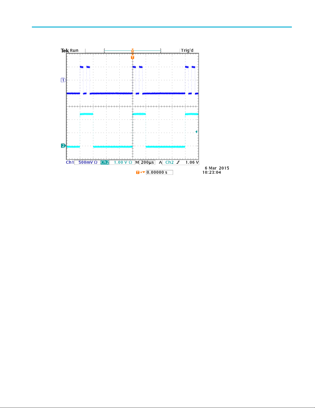
4. An example of a double pulse and a trigger output signal is shown as below
To Generate a Gated Burst Waveform
This outputs a continuous waveform when an effective gate signal is applied externally, when the manual
trigger button is depressed, when a remote command is applied, or during 50% of the selected internal
trigger interval.
In the gated burst mode, the output is enabled or disabled based on the internal gate signal or an external
signal applied to the front-panel Trigger Input connector. While the gate signal is true or the front-panel
Force Trig button is pushed in, the instrument outputs a continuous waveform.
1. Select the Burst run mode from the left sidebar menu.
2. Select Gate in the Mode field which means gated burst mode is enabled.
3. Select Manual from the Source drop down menu to enable the manual trigger.
Page 41

Operating Basics
To Generate a Gated Burst Waveform
AWG4162 Basic Application Help Document
35
33
4. Click on the Trigger button or push the front-panel Force Trig button .
5. Observe the gated burst waveform displayed on the oscilloscope screen.
Quick tips
Use the front-panel shortcut buttons to quickly select a waveform parameter.
The instrument provides the following three trigger sources for Burst mode:
Internal or external trigger signal.
Manual trigger (Force trigger).
Remote command.
Once Gate is selected, burst count parameters are ignored.
Page 42

Operating Basics
Sweep a Waveform
AWG4162 Basic Application Help Document
36
33
Sweep a Waveform
Sweep outputs a waveform with the output signal frequency varying in sweep type of Linear,
Logarithm, Upstair, and User Defined. You can set the following Sweep parameters:
Start frequency: the beginning value of the frequency sweep.
Stop frequency: the end value of the frequency sweep.
Sweep time: affects the length (time) of the measurement.
Return time: the amount of time from Stop Frequency to Start Frequency.
Center frequency: the frequency half way between the start and the stop frequencies.
Frequency span: the boundary of the frequency display.
Hold time: the amount of time that the frequency must remain stable after reaching the stop frequency.
1. Select a waveform function from the top of the Home tab.
2. Select the Sweep run mode from the left sidebar menu.
3. Specify the Start frequency, Stop frequency, Sweep time, Hold time, and Return time, as desired.
When you click on the Start frequency button, it toggles to the Center frequency. When you click on
the Stop frequency button, it toggles to the Span frequency.
4. Click on the sweep Mode field and select Trigger or Repeat.
5. Select the trigger source from the Source drop down menu.
Page 43

Operating Basics
Sweep a Waveform
AWG4162 Basic Application Help Document
37
33
6. This is a sample oscilloscope screen. The top is a sample of a sweep waveform. The bottom is a trigger
output signal.
Quick tips
For frequency sweep, you can select a Sine, Square, Ramp, More, or Arbitrary waveform. Pulse,
DC, and Noise waveforms cannot be selected.
Once the sweep is selected, the frequency is swept from the sweep start to the sweep stop frequencies.
Page 44

Operating Basics
Modulate a Waveform
AWG4162 Basic Application Help Document
38
33
If a start frequency is lower than a stop frequency, the instrument sweeps from the low frequency to
the high frequency.
If a start frequency is higher than a stop frequency, the instrument sweeps from the high frequency
to the low frequency.
If you want to return to the Sweep menu after selecting other menus, push the front-panel Sweep
button again.
Modulate a Waveform
To Output an AM Waveform
Amplitude modulation (AM) is a technique that varies the amplitude of the carrier waveform.
1. Select a waveform function from the top of the Home tab. This will be the carrier waveform.
2. Select the Modulation run mode from the left sidebar menu.
3. Specify the modulation type as AM by clicking on the Type field and selecting AM from the drop
down menu.
4. Select modulation source, set modulation frequency, select shape, and set modulation depth.
5. This is an example amplitude modulation waveform displayed on an oscilloscope screen.
Page 45

Operating Basics
To Output an AM Waveform
AWG4162 Basic Application Help Document
39
33
Quick Tips
You can output frequency modulation (FM) or phase modulation (PM) waveforms in the same way.
You cannot select Pulse, Noise, or DC as a carrier waveform.
You can select an internal or external signal as an AM source. If you select an external source and set
the modulation depth to 120%, the output will be at the maximum amplitude when a ±1 V
p-p
is applied to the rear panel Ext Mod Ch1 In or Ext Mod Ch2 In connector.
You can select a modulation shape from the internal memory or Local/USB memory.
The following equations show the output amplitude of AM, FM, and PM modulation (in this example,
sine waveform is used for carrier waveform and modulation waveform):
AM: Output(V
FM: Output(V
)= (1 + )
p-p
) =
p-p
signal
PM: Output(V
p-p
) =
Carrier amplit
Carrier frequ
ude
ency
Modulation frequency fm [Hz]
Time t [sec]
AM Modulation depth M [%]
FM Deviation D [Hz]
PM Deviatio
n
A [V
]
p-p
fc [Hz]
P [degree]
Page 46

Operating Basics
To Output an FSK Waveform
AWG4162 Basic Application Help Document
40
33
The following table shows relationship between modulation depth and maximum amplitude for AM
modulation waveform (internal modulation source is selected):
Depth Maximum amplitude
120% A (V
100% A (V
50% A (V
0% A (V
)
p-p
) * 0.909
p-p
) * 0.682
p-p
) * 0.455
p-p
To Output an FSK Waveform
Frequency Shift Keying (FSK) modulation is a modulation technique that shifts the output signal frequency
between two frequencies: the carrier frequency and hop frequency. The AWG4162 generates a phase
continuous FSK signal.
1. Follow the steps described in the To Output an AM Waveform procedure to display the
modulation type drop down menu. (See Modulate a Waveform.) In this example, select FSK
as the modulation type.
2. The FSK parameter setting screen is displayed. Select Internal or External as FSK Source.
3. If you select Internal, you can set the FSK Rate. If you select External, the FSK Rate is ignored.
Page 47

Operating Basics
To Output a PSK Waveform
AWG4162 Basic Application Help Document
41
33
4. Set Hop Frequency. Carrier waveform frequency shifts to the Hop frequency with the specified FSK
rate, and then returns to the original frequency.
To Output a PSK Waveform
Phase Shift Keying (PSK) modulation is a modulation technique that shifts the output signal phase between
two phases: the carrier phase and hop phase.
1. Follow the steps described in the To Output an AM Waveform procedure to display the
modulation type drop down menu. (See Modulate a Waveform.) In this example, select PSK
as the modulation type.
2. The PSK parameter setting screen is displayed. Select Internal or External as PSK Source.
3. If you select Internal, you can set the PSK Frequency. If you select External, the PSK Frequency is
ignored.
4. Set Hop Phase. Carrier waveform phase shifts to the Hop Phase with the specified PSK Frequency,
and then returns to the original phase.
Page 48

Operating Basics
To Output a PMW Waveform
AWG4162 Basic Application Help Document
42
33
To Output a PWM Waveform
Follow these steps to output a PWM waveform.
1. Select the Pulse function from the top of the Home tab to display the pulse parameter setting
screen.
2. Select the Modulation run mode from the left sidebar menu and the modulation type will be specified
as PWM automatically. Select the PWM Source.
3. Set the PWM Frequency, select the Modulation Shape, and set the Deviation (pulse width deviation).
Page 49

Operating Basics
Marker Out
AWG4162 Basic Application Help Document
43
33
Marker Out
The Marker out signal of the instrument is linked to run mode and function selected in the two channels
respectively.
1. Connect the front-panel Marker out connector and the external Trigger Input connector of the
oscilloscopes. The Marker out connector provides the trigger signal for oscilloscopes.
2. Continuous mode: The Marker out is a square waveform and the rising edge at the start of each
waveform period. When an output frequency is higher than 156.25 MHz, some restrictions are applied.
See the Quick Tips below.
Page 50

Operating Basics
Marker Out
AWG4162 Basic Application Help Document
44
33
3. Sweep mode: When the Repeat or Trigger sweep mode and trigger source are selected, the Marker
out is a square waveform and the rising edge at the start of each sweep.
4. Modulation mode: When internal modulation source is selected, the Marker out is a square waveform
of the same frequency as the modulating signal. When an external modulation source is selected, the
Marker out is disabled.
Page 51

Operating Basics
Marker Out
AWG4162 Basic Application Help Document
45
33
Start Frequency
Stop Frequency
Marker Frequency
0
100 MHz
Marker f = AO f
100 MHz
200 MHz
Marker f = AO f / 2
200 MHz
400 MHz
Marker f = AO f / 4
400 MHz
600 MHz
Marker f = AO f / 8
5. Burst Mode: When internal trigger source is selected, the Marker out is a square waveform and the
rising edge at the start of each burst period. When an external trigger source is selected, the Marker out
is high during the time the trigger input is high.
Quick Tips
The relationship of frequency between Marker Out and Analog Output (AO):
NOTE. The maximum frequency of Marker Out signal is 156.25 MHz.
NOTE. When the instrument outputs a modulation waveform, Marker Out signal cannot be output if
you select External as the modulation source.
The instrument provides the following three trigger sources for Burst mode:
Internal or external trigger signal.
Manual trigger (Force trigger).
Remote command.
Page 52

Operating Basics
Adjusting Parameters of Two Channel Signals
AWG4162 Basic Application Help Document
46
33
Adjusting Parameters of Two Channel Signals
To Align Phase
The AWG4162 uses a phase continuous method to change frequency. When you change a frequency of
one channel, it will affect the phase relationship between the two channels.
For example, the instrument is generating a 5 MHz sine waveform for both CH1 and CH2 and the phase is
adjusted between the two channels. If you change the CH2 frequency to 10 MHz and then return it to
5 MHz, the CH2 phase does not return to its initial condition. To adjust the phase relationship between
the two channels, you need to stop signal generation and restart it. The instrument provides an Align
Phase function to adjust the phase relationship.
1. Set the instrument to generate a continuous sine wave at 5 MHz for CH1 and CH2. Confirm that both
phases are set to 0 degrees.
2. View both channels at once by clicking the CH1/CH2/CHBOTH button and selecting CHBOTH.
Page 53

Operating Basics
To Align Phase
AWG4162 Basic Application Help Document
47
33T
3. Change the CH1 frequency to 10 MHz, and then back to 5 MHz. In this state, the CH2 phase does not
return to its initial condition.
4. To align the phase of two channel signals, push the Inter-CHs button and select Align Phase. The
instrument will stop signal generation, adjust the phases of both channels, and then automatically
restart signal generation.
Page 54

Operating Basics
To Match Amplitude
AWG4162 Basic Application Help Document
48
33
To Match Amplitude
To set the CH1 amplitude and CH2 amplitude to the same level, follow these steps:
1. To set both channels to the same amplitude, select the channel that has the desired amplitude. The
selected channel will have a colored rectangle around it in the status area.
2. Click the Inter-CHs button and select Amplitude CH1=CH2. The instrument will stop signal
generation, set the amplitude of both channels to match the selected channel, and then automatically
restart signal generation.
To Match Frequency/Period
To set the CH1 frequency and CH2 frequency to the same level, follow these steps:
1. To set both channels to the same frequency, select the channel that has the desired frequency. The
selected channel will have a colored rectangle around it in the status area.
Page 55

Operating Basics
Set up Load Impedance
AWG4162 Basic Application Help Document
49
33
2. Click the Inter-CHs button and select Frequency CH1=CH2. The instrument will stop signal
generation, set the frequency of both channels to match the selected channel, and then automatically
restart signal generation.
Set up Load Impedance
The output impedance of the AWG4162 is 50 Ω (in case of single-ended output). If you connect a load
other than 50 Ω, the displayed Amplitude, Offset, and High/Low values are different from the output
voltage. To make the displayed values same as output voltage, you need to set load impedance as follows:
1. Select the System tab and then select Setting from the left sidebar menu.
2. Click on Load in the desired channel to view the drop down menu.
3. To adjust the load impedance, select one of the following:
50 to set the load impedance to 50 Ω.
High Z to set the load impedance to approximate to infinite. When dBm is specified for the output
amplitude units, the amplitude units setting is automatically changed to Vpp if you select high.
Custom allows you to set the load impedance to a value of 1 Ω to 1 MΩ.
4. The load value is displayed in the Status menu.
Quick tips
Load impedance is applied to the amplitude, offset, high/low level, and VOCM settings.
Page 56

Operating Basics
Set up VOCM
AWG4162 Basic Application Help Document
50
33
AWG4162
(50ohm load, single-ended)
-2.5V ~ +2.5V
(high Z load, single-ended)
-5V ~ +5V
Set up VOCM
VOCM is “Voltage Output Common Mode” between + and – channels. In the case of differential output,
the negative output DC VOCM is the same value of the DC VOCM of the positive output.
1. Select the System tab and then select Setting from the left sidebar menu.
2. Click on the number field next to the VOCM in the desired channel.
Quick tips
VOCM isn’t related to what amplitude setting.
Maximum of VOCM is related to the load impedance as following:
Invert Waveform Polarity
You can use the Invert button on the left sidebar menu to invert the polarity of a generated waveform. The
following example shows how to get a differential signal using the invert function with a continuous sine
wave.
1. Set up the instrument to generate a continuous sine wave on CH1.
2. Set the frequency of CH1 to a desired value.
3. Click the CH1/CH2/CHBOTH button and select CHBOTH to view CH1 and CH2 simultaneously.
4. Click on the Inter-CHs button and select Frequency CH1=CH2 to set the CH2 frequency to match
CH1.
5. Click CH2 in the CH2 status bar.
6. Click on the Invert button on the left sidebar and notice that the CH2 waveform becomes inverted.
Page 57

Operating Basics
Add Noise
AWG4162 Basic Application Help Document
51
33
7. Push the front-panel Ch1 On button to enable the output.
Quick tips
See the Quick tutorial: How to generate a sine waveform topic for a quick tutorial on getting started
generating this waveform.
See the Adjusting parameters of two channel signals topic to read about how to quickly set the
frequency of one channel to match the other.
Add Noise
You can add the internal noise signal to a waveform using the following procedure. In this example, a
continuous sine wave is used.
1. Select the Sine function from the top of the Home tab.
2. Select the Continuous run mode from the left sidebar menu.
3. Select the System tab and then select Setting from the left sidebar menu.
4. Click on On/Off button next to Noise in the desired channel to turn on noise add function.
5. Click on the number field next to the Noise parameter on the AWG4162 and adjust it as desired. Noise
Level can’t be modified when Noise is Off.
Page 58

Operating Basics
Add Noise
AWG4162 Basic Application Help Document
52
33
6. Observe the waveform adding noise displayed on the oscilloscope screen.
7. The top waveform is the one before adding noise. The bottom waveform is the one after adding noise.
To avoid overflow by noise addition, the amplitude of the output signal is automatically halved.
Page 59

Operating Basics
Reference Clock Input
AWG4162 Basic Application Help Document
53
33
Reference Clock Input
1. The Reference Clock Input (Ref Clk In) and the Reference Clock Output (Ref Clk Out) connectors are
provided on the AWG4162 rear panel.
2. The instrument can use the internal or external source as a reference clock. To select a reference clock,
push the front-panel Utility button and then select Setting from the left sidebar menu.
3. Click on Clock Ref to toggle between Internal and External.
Quick Tips
The instrument can use the internal source or an external source as a reference clock. When the internal
reference is activated, a 10 MHz reference clock is output on the rear panel Ref Clk Out connector.
When the reference clock input is activated, the rear panel Ref Clock Input connector is used as the
input for an external reference clock.
Page 60

Operating Basics
Utility Menu
AWG4162 Basic Application Help Document
54
33
Utility Menu
Push the front-panel Utility button to display the System Tab. The System Tab provides access to utilities
used by the instrument such as system related menus, Self Calibration, and Self Diagnostics.
1. Push the front-panel Utility button to display the System Tab. Select the Setting from the left
sidebar menu to display the system related menus.
2. Clock Ref. (See Reference Clock Input.)
3. You can select the instrument Power On setting.
4. You can modify the Ext Clock Rate if select Clock Ref source as External.
5. Click on Beeper to toggle the beep sound Off and On.
6. Click on Click Tone to toggle the click tone Off and On.
7. You can modify High Limit and Low Limit for the desired channel.
8. Load Impedance. (See Set up Load Impedance.)
9. Noise. (See Add Noise.)
10. VOCM. (See Set up VOCM.)
Select the Status from the left sidebar menu to display the instrument status.
Page 61

Operating Basics
Utility Menu
AWG4162 Basic Application Help Document
55
33
Select the Tools from the left sidebar menu.
11. Warm Up Timer is used to calculate the warm up time.
12. Self Calibration (See Perform Instrument Self Calibration and Self Diagnostic.)
13. Self Diagnostic. (See Perform Instrument Self Calibration and Self Diagnostic.)
14. You can copy the waveform parameter of one channel to another channel by clicking on Copy CH1 to
CH2 or Copy CH2 to CH1.
15. Secure. (See Erase Custom Waveform Files.)
Page 62

Operating Basics
Save/Recall a Custom Setup
AWG4162 Basic Application Help Document
56
33
Save/Recall a Custom Setup
You can save up to four custom setups in the instrument internal memory. They are saved as Custom 1
through 4 under the File tab. You can save more setups to the Local Disk or a USB memory device.
Save a Custom Setup by UI
1. Click the File tab.
2. Click the desired Custom button which you want to save.
3. Click the save icon to save.
Save a Custom Setup by Front Panel.
1. Hold down the Custom1 button in front panel file area.
Page 63

Operating Basics
Save a Custom Setup by Front Panel
AWG4162 Basic Application Help Document
57
33
2. A warning dialog will show if the custom1 file exist.
3. Click Yes.
4. An information dialog will show “Custom1 setup has been saved”.
Page 64

Operating Basics
Recall a Custom Setup by UI
AWG4162 Basic Application Help Document
58
33
Recall a Custom Setup by UI
1. Click the File tab.
2. Click the desired Custom button to view the waveform parameters and make sure it is the desired
waveform. The parameters appear in the bottom half of the display.
3. Click to load the waveform file. You will now see the waveform on the AWG4162 display.
Recall a Custom Setup by Front Panel
1. Push the Custom1 button in front panel file area.
2. You will see the custom1 waveform display if custom1 exist. A warning dialog will show if the
custom1 doesn’t exist.
Quick tips
Click to lock a custom waveform file from being erased or edited.
Click to erase the selected custom waveform file.
Click to quickly navigate the four available custom files in the menu.
Click to open a custom waveform file.
Click to save a custom waveform file.
Page 65

Operating Basics
Save/Recall a Custom Setup for Different User by UI
AWG4162 Basic Application Help Document
59
33
Save/Recall a Custom Setup for Different User by UI
1. Click the File tab.
2. Click the desired User button to view the Recent Documents and Recent Places for different user.
You can rename the User 1-9 by double click.
Save a Screen Image
You can save a screen image of the instrument. Do the following steps:
1. Set the display to show the screen you want to save as image. Then simultaneously push the two arrow
keys underneath the rotary knob on the front panel.
2. A message appears on the screen, indicating that the screen image was saved.
Quick Tips
Image files are saved in the path "D:\Tektronix\AWG4000\Basic"
Image files are saved as .BMP format. The instrument gives all files created by the instrument the
default name yyyy-mm-dd-hh-mm-ss.BMP.
Page 66

AWG4162 Basic Application Help Document
60
Operating Basics
Erase Custom Waveform Files
33
Erase Custom Waveform Files
Erase instrument setups and waveforms from memory
You can also erase all instrument setups and waveforms from the instrument internal memory using the
following procedure.
NOTE. You can restore the instrument to its default settings at any time without erasing memory by
pressing the Default button located in the top right corner of the Basic mode display.
1. Click the System tab.
2. Click the Tools tab in the right sidebar menu.
3. Click the Secure button and the following dialog will appear.
4. Select OK to erase all setups and waveforms stored in hard drive X:\, or select Cancel to cancel the
operation.
Page 67

Operating Basics
ArbBuilder
AWG4162 Basic Application Help Document
61
33
ArbBuilder
You can create a waveform using the ArbBuilder tool. You can create new waveforms by selecting from
a list of standard functions, using the Equation Editor (See Create a Waveform by Equation.), or drawing
a waveform (See Draw a Waveform with ArbBuilder.).
You can open ArbBuilder from the Home tab by selecting New or Edit from the
drop down menu.
Create a Standard Waveform
1. Select ArbBuilder > New or Edit from the Home tab.
2. Select New Std from the Waveform tab.
3. Select a standard waveform from the Function drop down menu. You can choose Sine, Square,
Triangle, Pulse, Noise, DC, Exponential Rise, Exponential Decay, Sin(x)/x, Sweep, Multi Tone,
Lorentz waveform.
4. Adjust the vertical and horizontal parameters as desired.
5. Click the Preview button to view the waveform.
Page 68

Operating Basics
Create a Waveform by Equation
AWG4162 Basic Application Help Document
62
33
6. Click the OK button to view the waveform, or click Cancel to cancel and exit the window.
7. Click the SAVE button or SAVE AS button to save the waveform, or click Close button
to close the waveform.
8. Click table to turn to communication page.
9. Click Send to CH1 or Send to CH2 under communication tab to send this waveform
to the channel 1 or channel 2.
Create a Waveform by Equation
You can generate a waveform by equation editor. You can use this function in the ArbBuilder tool.
NOTE. The Equation editor processes all file inputs and outputs in the current working directory. The
current working directory must have read and write access or the equation file will not compile.
Equation Editor Overview
The Equation editor is an ASCII text editor that allows you to create, edit, load, and compile equation
waveform definitions into a waveform using the Waveform Programming Language (WPL). Use WPL to
generate a waveform from a mathematical function, perform calculations between two or more waveform
files, and use loop and conditional branch commands to generate waveform values. Compile the equation
file to generate the described waveforms.
Page 69

Operating Basics
Create a Waveform by Equation
AWG4162 Basic Application Help Document
63
33
The equation editor processes all file inputs and outputs in the current working directory. The current
working directory must have read and write access. Compilation may be dependent on the available
memory and other resources of the instrument.
An equation file is a text file that you create and edit in the equation editor. Select ArbBuilder > New
or Edit Waveform tab and click the New Equa icon to open the equation
editor.
The following table describes the screen elements of the equation editor.
Element Description
Toolbar Provides edit operations, such as open, save, cut, copy, and paste.
File name The file name to which the equation or text is written, or the name of the file being
edited. The instrument appends the default .equ file extension to all Equation editor
files.
Equation
The area where you enter text and/or equation information.
Output Displays the status of the compilation. If the compilation fails, then the application
displays an error message. If the compilation is successful, then the application
displays “Compiled Successfully”.
Command List Keypad of math functions, numbers, and letters for creating equations.
Preview Display of waveform graph after compile.
Compile Button that compiles the currently loaded or edited equation file. The status of the
compilation is displayed in the output window.
Settings Provides controls for adjusting range and points.
OK and Cancel buttons Use these buttons to save and exit (OK) or cancel and exit (Cancel) the Equation
Editor window.
Page 70

Operating Basics
Create a Waveform by Equation
AWG4162 Basic Application Help Document
64
33
Component
Symbol
Meaning
Example
Syntax Items
( )
These are parentheses — (and) — for specifying
the order of operations. Each opening (left)
parenthesis must be paired with a closing (right)
parenthesis. When there are two arguments – for
example, range, max, min – they are separated
with a , (comma).
NA
Variables. Here
are the variables
that can be used
in an equation.
t
x
v
Time from the head of that range() statement
Variable taking on a value from 0.0 to 1.0 within
that range ( )
Variable showing the current value of the waveform
data at that position statement
NA
Operators
+, –, *, /
These add, subtract, multiply, or divide the
components. The priorities are the same as usual
for these four operators – * and / have priority over
+ and –.
NA
^
Expresses exponents. Only integers can be raised
to a higher power. ^ has the same priority as * and
/. Therefore, parentheses are required to give
priority to multiplication.
pi * (2^3) * x where 2^3 = two raised
to the third power.
Comment
#
Comments are preceded by a number sign (#).
When a number sign is entered, all characters after
that until the end of the line are treated as a
comment. All of the items in the component menu
can be used in a comment.
NA
Characters
a–z, %, $, &,
@, A, _
The characters available in the component menu
are the letters of the alphabet (a–z) and several
symbols (%, $, &, @, A and _ ). These are used in
comments.
NA
The component menu contains the items used to set the time range as well as functions, operators, variables,
constants, syntax items and characters. You can use these items to create equations and enter comments.
Page 71

Operating Basics
Create a Waveform by Equation
AWG4162 Basic Application Help Document
65
33
Other items
pi, e, k, =,
NA
pi
The circumferential ratio.
NA
e
Exponent (for an implied 10). The range for
numbers expressed in this scientific notation is from
|5.9e–39| to |3.4e38|.
1e6=1,000,000, 1e–3=0.001
k
The k0–k9 can be specified; these are constants
that may be used in equations. Specifying a new
value for the same k# replaces the old value with
the new one. If no constant
is defined for k, this value will be automatically set
to 0.
NA
= Equals sign. = is used with k constants.
k0=2*pi
Ends the line for the range or equation; inserting a
return
( ) in the middle of the line partitions it.
NA
Functions
sin(, cos(
The arguments for these trigonometric functions are
in radians.
range(0,100 s)cos(2*pi*x)
Example:
range(0,100 s)sin(2*pi*1e4*t)
exp(, log(, ln(
Exponential function, common log function, natural
log function. The log and ln arguments must be
positive.
range(0,50 _s)
1–exp(–5*x)
range(50 _s,100 _s)
exp(–5*x)
Example: range(0,100 _s)
log(10*(x+0.1))
Example: range(0,100 _s)
ln(2*(x+0.2))
sqrt(
The square root; the argument must be a positive
value.
range(0,100 _s)
sqrt(sin(pi*x))
abs(
The absolute value.
range(0,100 _s)
abs(sin(2*pi*x))
int(
Truncates the fraction to obtain the integer.
range(0,100 _s)
int(5*sin(2*pi*x))/5
round(
Rounds off the fraction to obtain the integer.
range(0,100 _s)
round(5*sin(2*pi*x))/5
norm(
Normalizes the range specified with range() and
scales the amplitude values so that the maximum
absolute value is 1.0 (that is, a value of +1.0 or –
1.0). The norm() statement comprises an entire
line.
range(0,100 _s)
sin(2*pi*x)+rnd()/10
norm()
max(
min(
Takes the larger of two values.
Takes the smaller of two values.
range(0,100 _s) sin(2*pi*x)
range(0,50 _s) min(v,0.5) range(50
_s,100 _s) max(v,–0.5)
Page 72

Operating Basics
Create a Waveform by Equation
AWG4162 Basic Application Help Document
66
33
range(
The equation must specify the time domain. If the
time domain is not defined, this is an error. The
time domain is specified with range().
When making a new equation file, range(0, is input
in the first line of equation. Next, the time is
specified. This setting is valid until the next
range( item is specified. With the first range()
specification, any number of lines of equation
can be input. Text written after the range() on the
same line is invalid. Here is the format for the
range( item.
range( Equation starting time, Equation ending
time )
range(0,1ms) Time range sin(2*pi*x)
Equation
rnd (integer
from 1 to
16,777,215)
When an argument is specified, generates a
random number sequence using that argument as
the initial value. If the argument is omitted, 1 is
used.
range(0,100 _s)
rnd(2)/3
diff(
Differentiates the function over the range specified
with range(). Specified with diff(). The diff()
comprises an entire line.
range(0,33 _s)
–0.5
range(33 _s,66 _s)
0.5
range(66 _s,100 _s)
–0.5
range(0,100 _s)
diff()
integ(
Integrates the function over the range specified with
range(). Specified with integ(). The integ()
comprises an entire line. After integ(), specify
normalization (norm()) as necessary.
range(0,33 _s)
–0.5
range(33 _s,66 _s)
0.5
range(66 _s,100 _s)
–0.5
range(0,100 _s)
integ()
norm()
mark (marker1
or marker2)
Sets the marker for the range set with range(). After
compiling, there is no marker display, but the set
marker can be verified with the waveform editor.
The mark() statement comprises an entire line. For
example, when mark(1) is input, nothing else can
be input on that line.
NA
Page 73

Operating Basics
Create a Waveform by Equation Editor
AWG4162 Basic Application Help Document
67
33
Unit
Meaning
m
milli (e
– 3
)
u
micro (e
– 6
)
n
nano (e
– 9
)
p
pico (e
– 12
)
s
second
,
comma separator
K
Kilo (e3)
M
Mega (e6)
Button
Meaning
Enter
Confirms the selection and moves to the next line of the equation
BKSP
Backspaces over the last character. Works like the backspace key on the keyboard
CLR
Clears the entire equation
Use the equation editor Units menu to specify the units for the parameters or variables used in the equation.
The following table lists the units that you can use and their descriptions.
Use the selection menu to confirm, backspace, or clear the equation. The following table lists the units that
you can use and their descriptions.
Create a Waveform by Equation Editor
1. Select ArbBuilder > Edit > Waveform tab and click the New Equa icon to open the
2. In the Equation Editor window, enter text to form a waveform equation. For example, type
equation editor.
“Log(w)” in equation input box.
Page 74

Operating Basics
Create a Waveform by Equation Editor
AWG4162 Basic Application Help Document
68
33
3. Click Compile button to generator a waveform in the preview box. You will see “Compiled
Successfully” information in the Output box and a log waveform display in the Preview box. If you
enter an invalid equation, the Output Box will show error warning message and the error line in the
equation input box will turn to red.
Page 75

Operating Basics
Save a Waveform Equation
AWG4162 Basic Application Help Document
69
33
4. Click the OK button to display the waveform in editable mode, or click Cancel button to cancel the
operation.
5. You will see a log waveform. You can edit, save or send it to channel 1 or 2.
NOTE. The equation editor supports only the basic 7-bit ASCII character set. The maximum length of a
single string is 256 characters, including spaces. Concatenate strings by entering a colon character (:) at the
end of a line. The maximum length, that is, sum of all string lengths is 1000.
Save a Waveform Equation
1. Create a waveform equation by following step 1 – 3 in the “Create a waveform equation”.
2. Click button in the equation editor toolbar.
3. A Windows save as dialog box will show up. Enter a filename and save. The equation file will be
saved in the .eqa format file.
Open an Equation File
1. In the Equation Editor window, click in the equation editor toolbar.
2. Select an existing waveform equation file and click Open.
Page 76

Operating Basics
Open a Waveform with ArbBuilder
AWG4162 Basic Application Help Document
70
33
Edit an Equation File
In the Equation Editor window, you can do the following to modify equations:
Cut. Highlight the part of the equation you want to cut and then click this icon .
Copy.
Highlight the part of the equation you want to copy and then click this icon .
Paste. Highlight the part of the equation you want to paste and then click this icon .
Directly edit the text using a keyboard or the Command List keypad.
Open a Waveform with ArbBuilder
1. Select ArbBuilder > New or Edit to open the ArbBuilder tool.
2. Select Open button from the Waveform tab.
3. The windows file open dialog box pop up. Please select an existing waveform file. ArbBuilder
supports several formats of waveform, such as .wfm, .pat, .txt, .tfw and .isf. The formats supported by
ArbBuilder.
4. You can open the files with 5 methods:
Open in New Tab: You can open the file in a new tab.
Insert at the End: You can insert the new file at the end of current waveform.
Insert at the Beginning: You can insert the new file at the beginning of current waveform.
Insert at Active Cursor: There are two cursors on the waveform view. Click the cursor you want to
insert new waveform. Then click OK, the new file at the cursor of current waveform.
Replace between Cursors: There are two cursors on the waveform view. The new waveform will be
inserted between the two cursors.
5. Click OK, the file will be opened.
Page 77

Operating Basics
Draw a Waveform with ArbBuilder
AWG4162 Basic Application Help Document
71
33
Redo is used to restore the previous state.
Undo is used to restore the next state.
Zoom In is used to enlarge the waveform graph.
Zoom Out is used to shrink the waveform graph
Horizontal Zoom In is used to enlarge the waveform graph in horizontal
direction.
Fit To Window is used to restore the default state of waveform.
Move With Hand is used to move the waveform by hand.
Draw a Waveform with ArbBuilder
1. Open a waveform. You can open a standard waveform (See Create a Standard Waveform.).
2. Click the Draw tab.
3. Use the icons in the Draw toolbar to create your waveform.
4. Freehand means you can draw waveform on both horizontal and vertical points. Horizontal
means you can draw waveform on horizontal direction. Vertical means you can draw
waveform on vertical method. Point means you can draw some points and the points can be
interpolated in the way of linear, smooth or staircase.
Page 78

Operating Basics
Draw a Waveform with ArbBuilder
AWG4162 Basic Application Help Document
72
33
5. If you select Point icon , then the Point Draw toolbar appears. You can click on the graph,
select points and then use the toolbar icons to edit them. You can use tools in the following table.
6. If you click Table icon , the Point Draw Table window will open. You can enter points
directly
into this table and click OK to save.
You can Insert, Delete or Clear all the data points.
Page 79

Operating Basics
Edit a Waveform with ArbBuilder
AWG4162 Basic Application Help Document
73
33
7. You can select from the interpolation menu and apply one of the three selections to the
waveform. Linear: Points can be connected with straight line. Smooth: Points can be connected with
smooth line. Staircase: Points can be connected with staircase.
Edit a waveform with ArbBuilder
1. Open a waveform. Please see Open a Waveform with ArbBuilder.
2. Click ArbBuilder->Edit. You will see the edit toolbar.
Page 80

Operating Basics
Edit a Waveform with ArbBuilder
AWG4162 Basic Application Help Document
74
33
Item
Description
Paste at the End
Paste a waveform segment at the end of
a waveform
Paste at the Beginning
Paste a waveform segment at the
beginning of a waveform
Paste at the Active Cursor
Paste a waveform segment behind an
active cursor.
Replace between the Cursors
Replace the waveform between the
cursors by a waveform segment.
3. Cut . It is used to cut a piece of waveform data between the two cursors.
4. Copy . It is used to copy a piece of waveform data between the two cursors. The waveform will not
be changed.
5. Paste . If the Paste button is clicked, a dialog box is pop up. There are four paste options.
Page 81
Operating Basics
Edit a Waveform with ArbBuilder
AWG4162 Basic Application Help Document
75
33
Item
Description
Waveform Library
There are seven kinds of waveform which are Sine,
Square, Triangle, Pulse, Noise, Exponential Rise,
Exponential Decay.
Scalar Value
An amplitude value set by the user
Copy from clipboard
A piece of waveform from Copy or Cut operation.
6. Math
It is used to make an arithmetic for a waveform. The arithmetic contains four operations which are
addition, subtraction, multiplication and division. When the Math button is clicked, a dialog box
is pop up.
There are three kinds of math sources which are waveform library, scalar value and copy from
clipboard.
Page 82

Operating Basics
Edit a Waveform with ArbBuilder
AWG4162 Basic Application Help Document
76
33
7. Invert . It is used to overturn the waveform between the cursors in the vertical direction.
Page 83

Operating Basics
Edit a Waveform with ArbBuilder
AWG4162 Basic Application Help Document
77
33
8. Mirror . It is used to overturn the waveform between the cursors in the horizontal direction.
Page 84

Operating Basics
Edit a Waveform with ArbBuilder
AWG4162 Basic Application Help Document
78
33
Item
Description
Points
Set the point number which is moved each time
Amplitude
Set the amplitude which is moved each time
Rotate
Move the waveform periodically
Horizontal Shift
Move the waveform and use zero to fill the
data after the waveform
9. Shift/Rotate . When the user clicks the Shift/Rotate button, a panel is pop up in the right of
main panel zone. The waveform display zone will shrink.
Shift left is used to move the waveform left.
Shift right is used to move the waveform right.
Shift up is used to move the waveform up.
Shift down is used to move the waveform down.
Shift/Rotate can pop up a dialog and realize the shift/rotate function all the same.
Page 85

Operating Basics
Send a Waveform to CH1/CH2
AWG4162 Basic Application Help Document
79
Send a Waveform to CH1/CH2
1. Click Communication in the ArbBuilder.
2. Click Send to CH1 or Send to CH2 . You will see a progress bar. The waveform is sent
to Basic.
Page 86

Appendix
Touch Panel Calibration
AWG4162 Basic Application Help Document
80
Appendix
Touch Panel Calibration
1. Double click “Microchip AR Configuration Utility” on the desktop.
2. Choose “Configuration Wizard”.
Page 87
Appendix
Touch Panel Calibration
AWG4162 Basic Application Help Document
81
3. After click next will show below dialog, please choose “AR1100 Dev Kit”.
4. After that it will show the dialog as below, please choose “USB” and “Digtizer”, and please wait.
Page 88
Appendix
Touch Panel Calibration
AWG4162 Basic Application Help Document
82
5. Please click next until it shows below dialog, after that please click “Next”, and finished.
6. Please close this application.
7. Please double click “Microchip AR Configuration Utility” on the desktop again, and choose “Manual
Setup”.
Page 89

Appendix
Touch Panel Calibration
AWG4162 Basic Application Help Document
83
8. It will show below picture that let you click the plus to calibrate touch panel.
9. After touch all the pluses , when it will show below picture means you can close application and
complete the calibration.
Page 90

Appendix
Default Settings
AWG4162 Basic Application Help Document
84
Menu or System
Default setting
Output
configuration
Function
Sine
Frequency
1.000 000 000 00 MHz
Amplitude
1.000 Vp-p
Offset
0 mV
Symmetry (Ramp)
50.0%
Duty (Pulse)
50.0%
Output Units
Vp-p
Output Impedance
50Ω
Output Invert
Off
Output Noise Add
Off
Output High Limit
2.500 V
Output Low Limit
-2.500 V
VOCM
0 mV
Modulation
Modulation Waveform
10.00 kHz, Sine (except FSK,PSK)
Modulation Waveform
10.00 kHz, Square (FSK,PSK)
AM Depth
50.0%
FM Deviation
1.000 000 MHz
PM Deviation
90.0
FSK Hop Frequency
1.000 000 MHz
FSK Rate
10.000 000 0 kHz
PWM Deviation
5.0%
PSK Frequency
10.00 kHz
PSK Hop Phase
90.0
Sweep
Sweep Start Frequency
100.000 kHz
Sweep Stop Frequency
1.000 000 MHz
Sweep Time
10 ms
Sweep Hold Time
0 ms
Sweep Return Time
1 ms
Sweep Type
Linear
Sweep Mode
Repeat
Sweep Source
Internal
Trigger Slope
Positive
Trigger Interval
1.000 ms
Input Threshold
0.00 V
Step Num
1
Burst
Burst Mode
Triggered
Burst Count
5
Trigger Source
Internal
Trigger Delay
0.0 ps
Trigger Interval
1.000 000 ms
Slope
Positive
Input Threshold
0.00 V
Phase
0.00°
System-related
settings
Clock Reference
Internal
Ext Clock Rate
10 MHz
Default Settings
The following table lists the settings that are restored when you push the front-panel Default button or send
SCPI command “*RST”.
Page 91

AWG4162
Arbitrary Waveform Generator
Advanced Application
Page 92

Contents
Preface ............................................................................................................................................. 7
Documentation ........................................................................................................................... 7
Getting Started ................................................................................................................................. 8
General Features .......................................................................................................................... 8
Operating Requirements .............................................................................................................. 9
Standard Accessories ................................................................................................................. 11
Recommended Accessories ....................................................................................................... 11
Powering the Instrument On and Off ........................................................................................ 12
Protect Your Instrument from Misuse ....................................................................................... 12
Update Your Instrument Firmware ............................................................................................ 13
Install Advanced APP .............................................................................................................. 13
Uninstall Advanced APP ......................................................................................................... 16
Remote Control .......................................................................................................................... 18
Overheat Protection .................................................................................................................. 24
Getting Acquainted with Your Instrument .................................................................................... 25
Front Panel Overview .......................................................................................................... ....... 25
Rear Panel .................................................................................................................................. 26
Advanced Application Introduction ............................................................................................... 27
Sequence ...................................................................................................................... .............. 27
Subsequence ................................................................................................................... ........... 28
Entry ......................................................................................................................... .................. 28
Segment ..................................................................................................................................... 28
Component ................................................................................................................................ 28
Workspace ................................................................................................................................. 29
Single Sequencer .................................................................................................................... 29
Multi Sequencer ..................................................................................................................... 29
Mixed (analog/digital) waveforms ............................................................................................. 30
Advanced UI Introduction ...................................................................................................... ........ 31
Start Page ................................................................................................................................... 31
Self-Diagnostic ........................................................................................................................... 32
Self-Calibration ........................................................................................................................... 33
4
Page 93

Home Page ................................................................................................................................. 40
Settings ...................................................................................................................................... 46
Settings - The Run Mode Tab ....................................................................................................... 47
Settings - The Analog Ch Tab (ARB Mode) ................................................................................... 48
Settings - Digital Channels Tab ..................................................................................................... 50
Settings - Timing Tab .................................................................................................................... 53
Settings - Events Tab (Single Sequencer) ...................................................................................... 54
Settings - Events Tab (Multi Sequencer) ....................................................................................... 56
Settings - Dynamic Jump .............................................................................................................. 57
Waveform Window .................................................................................................................... 58
Cursors Tools ................................................................................................................................ 60
Zoom Tools .............................................................................................................................. 66
Analog Waveform Graph Tools .................................................................................................... 66
Waveform Standard Editor Window ............................................................................................ 69
Effect Settings and Parameters Window (Analog Waveforms Only) ........................................... 73
Digital Waveform Graph Tools ..................................................................................................... 97
Mixed Signal Waveform Editor..................................................................................................... 99
Analog Waveform Editor .............................................................................................................. 99
Digital Waveform Editor ............................................................................................................. 110
Data Editor ................................................................................................................................. 112
Sequence Window ................................................................................................................... 114
Input Waveform Properties ....................................................................................................... 116
Main Sequencer window ............................................................................................................ 118
Waveform and Table View of the Sequencer ............................................................................ 120
Editing a Sequence ..................................................................................................................... 121
Waveform View Window ......................................................................................................... 135
Tutorials ....................................................................................................................................... 138
How do I Examples ................................................................................................................... 138
Creating Your First Analog Waveform ........................................................................................ 138
Creating a Sequence of Waveforms ........................................................................................... 143
Importing a Waveform + Component Usage + Gated Run Mode .............................................. 153
Creating Digital Waveforms ....................................................................................................... 161
7
Page 94

Common Tasks Examples ......................................................................................................... 170
Create a New Workspace ........................................................................................................... 170
Open an Existing Workspace ...................................................................................................... 176
Demo Project ............................................................................................................................ 176
Option Installation .................................................................................................................... 177
Multi-Instrument System ......................................................................................................... 179
Appendix ....................................................................................................................................... 185
A. Digital Outputs ..................................................................................................................... 185
B.Touch Panel Calibration ........................................................................................................ 188
8
Page 95

Item
Purpose
Location
Compliance and Safety
Instructions
Compliance, safety, and basic installation
information
Printed and
shipped with
your instrument
Advanced Application Help
Advanced Application operating
information
Instrument and
available as a
PDF at
www.tek.com/
manuals
Basic Application Help
Basic Application operating information
Instrument and
available as a
PDF at
www.tek.com/
manuals
Programmer Manual
Programming syntax and command
information for remotely controlling the
instrument
Instrument and
available as a
PDF at
www.tek.com/
manuals
Service Manual
Instrument servicing procedures and
replaceable parts list
Instrument and
available as a
PDF at
www.tek.com/
manuals
Specifications and
Performance Verification
Technical Reference
Instrument specifications and
performance
verification procedures
Instrument and
available as a
PDF at
www.tek.com/
manuals
Declassification and Security
Instructions
Describes how to sanitize, secure, and
declassify the instrument
Instrument and
available as a
PDF at
www.tek.com/
manuals
Preface
This document contains information about how to use the Advanced Application of the Tektronix AWG4162 Arbitrary
Waveform Generator, along with basic operations and concepts.
Documentation
The following table lists related documentation available for your AWG4162. The documentation is available
on the Document CD and on the Tektronix Web site (www.tektronix.com/manuals).
9
Page 96

Getting Started
General Features
Two working modes
o Basic (DDS) mode
Two analog channels
600 MHz sine waveforms
2.5 GS/s, 14-bit, 16 kpts arbitrary waveforms
Amplitude up to 5 Vp-p into 50 Ω load
o Advanced (Arbitrary) mode
Two analog channels
16/32-bit digital channels (optional)
1/16/32/64 Mpts per channel arbitrary waveform memory (optional)
Up to 750 MHz bandwidth
SFDR < -60 dBc
Variable sampling rate range from 100 S/s to 2.5 GS/s, with 14-bit vertical resolution, ensures signal
integrity in all aspects
Designed for 100% user-conducted upgrades and configurations, all options activated through SW
key
o Optional and upgradable arbitrary waveform memory up to 64 Mpts for each analog channel
and 32 Mbit for each digital channel for long waveforms
o Optional 16-32 channel digital outputs. Purchasing SW option includes the shipment of
digital probe accessory.
Dual analog channels and up to 32-bit digital channels, ideal for mixed signal circuit designs
Sync-in and Sync-out interfaces enables the synchronization of multiple units in a daisy chain, to
extend the number of output channels
Digital outputs provide up to 1.25 Gb/s data rate creates high speed digital pattern in parallel
One marker output for each analog channel for triggering and synchronization
Three software-configurable output paths fit all test cases
o Direct DAC mode: 750 MHz bandwidth with differential output
o AC coupled mode: 750 MHz bandwidth with single ended output for RF applications
o Amplified mode: 5 Vp-p amplitude 400 MHz bandwidth with differential output
Full functional sequence with up to 16384 user defined waveforms provides the possibility of
generating complex signals with the best memory usage, in the form of loops, jumps, and conditional
branches
Channel 1 and 2 (together with the corresponding digital output channels) can work independently
on different sampling clocks and sequences
Direct communication with RFXpress® for easy waveform generation in RF applications
Windows based platform with 10.1-in touch screen, front panel buttons,keyboard, and mouse
Compact form factor, convenient for bench top and portability Removable hard disk guarantees the
security of confidential data
USB 3.0 and LAN interfaces for remote control
10
Page 97

Operating Requirements
Power supply
Source voltage and frequency 100 to 240 Vrms @ 50 - 60 Hz
115 Vrms @ 400 Hz
Power consumption max 150 W
Surge current 30 A peak (25 °C) for ≤ 5 line cycles, after product has been turned off for at least 30 s
Physical characteristics
Weight (typical)
Net weight 6.5 kg (14.2 lbs)
Net weight with packaging 11.5 kg (25.2 lbs)
Dimensions
Height 233 mm (9.17 in.)
Width 439 mm (17.28 in.)
Depth 199 mm (7.82 in.)
Dimensions with packaging(typical)
Height 498 mm (19.61 in.)
Width 457 mm (17.99 in.)
Depth 574 mm (22.60 in.)
Clearance ≥50.8 mm (2.0 in.) on left and rear sides of the instrument
Temperature
Operating +5 °C to +50 °C (+41 °F to 122 °F)
Non-operating -20 °C to +60 °C (-4 °F to 140 °F)
Humidity
Operating 8% to 90% relative humidity with a maximum wet bulb temperature of 29 °C at or below
+50 °C, non-condensing
Non-operating 5% to 98% relative humidity with a maximum wet bulb temperature of 40 °C at or below
+60 °C, non-condensing
11
Page 98

Altitude
Operating 3,000 m (9,843 feet)
Non-operating 12,000 m (39,370 feet)
12
Page 99

Item
Description
Manual
COMPLIANCE AND SAFETY INSTRUCTIONS
Product CD
Document CD with Browser Including the PDF files of
Specs & PV Tech Ref, user manual, programmer,
service manual.
Power Cable
-
USB cable
-
Stylus
For touch panel
Front protect
cover
-
Accessory Pouch
-
50Ω SMA
Terminator
Male, DC-18GHz; 1 ea / channel
Certification of
Calibration
-
Three year
warranty
-
Item
Description
Pin Header
SMA Cable
45 inch
RMD5000
- Rack mount kit
- Instruction sheet (English)
Manual
Service (English)
Specs & PV Tech Ref
Programmer manual
AWG4HDDE
- Hard disk drive
SMA
terminator
50 Ω
Standard Accessories
Recommended Accessories
13
Page 100

AWG4SYNC
Sync cable; Used for multiple instruments
synchronization
RFX100
RFXpress software
AWG4DIG16LVDS
16-bit digital output cable; Used for LVDS
AWG4DIG16TTL
16-bit digital output adaptor; LVDS to
TTL/CMOS
AWG4DIGSCKT
Digital output connector; AWG4k Digital
Channel Connector on DUT (Amphenol, U65B12-40E0C)
TEK-USB-488
GPIB to USB adaptor
HCTEK54
Hard transit case
Powering the Instrument On and Off
Power On
1. Insert the AC power cord into the power receptacle on the rear panel.
2. Use the front-panel power button to power on the instrument.
3. Wait until the system shows windows desktop.
4. You have two selections to open the applications:
You can press the “Basic” or “Advanced” Buttons on front panel to launch one application. You can also click the shortcut
icons on desktop to launch any one of them.
NOTE:
Only one application can be launched at same time. If you want to launch the other application, please close the
first one at first.
Power Off
1. Please close the application that you are using at first.
2. Use the front-panel power button to power off the instrument.
14
 Loading...