

Page 1

ASO-PI0 -$-
Quick Start
USER’S GUIDE
Page 2

ASO-PI0 Quick Start
User’s Guide
Revision A - January 1996
Part Number: 95180
Page 3

The information contained in this manual is believed to be accurate and reliable. However, Keithley
instruments, Inc., assumes no responsibility for its use or for any infringements of patents or other rights
of third parties that may result from its use. No license is granted by implication or otherwise under any
patent rights of Keithley Instruments, Inc.
KEITHLEY INSTRUMENTS, INC., SHALL NOT BE LIABLE FOR ANY SPECIAL, INCIDENTAL.
OR CONSEQUENTIAL DAMAGES RELATED TO THE USE OF THIS PRODUCT. THIS
PRODUCT IS NOT DESIGNED WITH COMPONENTS OF A LEVEL OF RBLIABlLITY
SUITABLE POR USE IN LIFE SUPPORT OR CRITICAL APPLICATIONS.
Refer to your Keithley Instruments license agreement for specific warranty and liability information,
MetraByte is a trademark of Keithley Instruments, Inc. AU other brand and product names are
trademarks or registered trademarks of their respective companies.
0 Copyright Keithley Instruments, Inc., 1996,
All rights resewed. Reproduction or adaptation of any part of this documentation beyond that permitted
by Section 117 of the 1976 United States Copyright Act without permission of the Copyright owner is
unlawful.
Keithley MetraByte Division
Keithley Instruments, Inc.
440 Myles Standish Blvd. Taunton, MA 02780
Telephone: (508) 880-3000. FAX: (508) 880-0179
Page 4

Table of Contents
Preface . . . . . . . . . . . . . . . . . . . . . . . . . . . . . . . . . . . . . . ..v
Setup and installation
Installing the ASO-PI0 Software Package
Using the Configuration Utility.
Using the Control Panel. ................................
Summary of Functions . . . . . . . . . . . . . . . . . . . . . . . . . 7
Programming Flow Diagrams.. . . . . . . . . . . .
Preliminary Steps for All Digital I/O Operations
Steps for Single-Mode Digital Input Operations,
Steps for Single-Mode Digital Output Operations.
Steps for Intermpt-Mode Digital Input Operations.
Steps for Interrupt-Mode Digital Output Operations.
Steps for Reading a Digital Output Value
Steps for Generating a Windows Event.
List of Tables
Table 1. Default Configuration . . . . .3
Table 2. Summary of Functions. .7
............................
...................
.......................... .3
.
. . . . . 9
. . . ..I0
. . . ..I1
. . . ..I3
1
I
.5
9
.I0
.I6
.I7
Page 5

Page 6

Preface
The
ASO-PI0 Quick Start User’s Guide
writing application programs for the following boards using the PI0
Series Function Call Driver:
PIO-12 PIO-24 PIO-96 PIO-HV
describes how to get started
PIO-321N
REL-16 DASCard-PI012 PIO-SSR-24 PIO-SSR-48
PIO-SSR-120
These boards and cards are referred to as PI0 Series boards,
The PI0 Series Function Call Driver supports the following
Windowsw-based languages:
. Microsoft’ Visual C++” (Version 1.5 and higher)
l
Borland@ C/C++ (Version 4.0 and 4.5)
. Microsoft Visual Basic@ for Windows (Version 3.0 and higher)
The
ASO-PI0 Quick Start User’s Guide
programmers using a PI0 Series board in an IBM” PC AT” or
compatible computer. It is assumed that you are experienced in
programming in your selected language and that you are familiar with
data acquisition principles. In addition, it is assumed that you have read
the user’s guide for your PI0 Series board to familiarize yourself with the
board’s features and that you have completed the appropriate hardware
installation and configuration.
PIO-320UT
PIO-321/O
is intended for application
PDISO-8
Page 7

The
ASO-PI0 Quick Start User’s Guide
is organized as follows:
. Setup and Installation
describes how to install the ASO-PI0
software package, how to configure the boards, and how to use the
control panel to test the boards.
. Summary
OP Functions contains a brief description of each of the
PI0 Series Function Call Driver functions. Refer to the PI0 Series
Function Call Driver online help for a more detailed description of
the functions.
l
Programming Flow Diagrams
contains a series of flow diagrams
showing the steps required to perform each of the operations
supported by the PI0 Series Function Call Driver. Refer to the PI0
Series Function Call Driver online help for a more detailed
description of the required procedures.
Note:
All PI0 Series boards except for the PIO-SSR-24, PIO-SSR-48.
and PIO-SSR-120 are shipped with the following two disks:
l
PI0 Family Software
-Use this disk for DOS application programs
and for older Windows application programs that use the Port I/O
software (PORTIO.DLL). Copy the files from this disk to an
appropriate directory. For more information, refer to FILES.TXT.
which lists and describes all the copied files; PORTIO.TXT, which
describes how to use the Port I/O software; and README.TXT.
vi
l
PI0 Family Advanced SW (ASO-PI0 software package)
Use
this disk for all new Windows application programs that use the PI0
Series Function Call Driver. The
ASO-PI0 Quick Start User’s Guide
is intended for use with the ASO-PI0 software package only.
PIO-SSR-24, PIO-SSR-48, and PIO-SSR-120
boards
are shipped with the
PI0 Family Advanced SW disk (ASO-PI0 software package) only.
Page 8

Setup and Installation
Before you use the PI0 Series Function Call Driver to program your PI0
Series boards, perform the following tasks:
1. Unpack and inspect your PI0 Series boards. Refer to the user’s guide
for your PI0 Series board for information.
2. Install the ASO-PI0 software package. Refer to the next section,
“Installing the ASO-PI0 Software Package,” for information.
3. Configure your PI0 Series boards by specifying the appropriate
configuration options in the PI0 Series Contiguration Utility. Refer IO
“Using the Configuration Utility” on page 3 for information.
4. If required, set jumpers and switches on the boards appropriately.
Refer to the user’s guide for your PI0 Series board for information
5. Install the PI0 Series boards in your computer and attach the
appropriate signals. Refer to the user’s guide for your PI0 Series
board for information.
6. Test the functions of the PI0 Series boards using the PI0 Series
Control Panel. Refer to “Using the Control Panel” on page 5 for
information.
7. Look at the example programs provided with the ASO-PI0 software
package. Refer to the FILESTXT file in the installation directory for
a list and description of the example programs.
Installing the ASO-PI0 Software Package
To install the ASO-PI0 software package, perform the following steps:
1. Make a back-up copy of the disk labeled PI0 Family Advanced SW.
Use the copy as your working disk and store the original as a backup
disk.
2. Insert the disk into the disk drive.
3. Start Windows, if necessary.
1
Page 9

4. Invoke the SETUI!EXE installation utility.
Assuming that you are using disk drive A. choose File\Run (for
Windows 3.1) or StartJRun (for Windows 95), type the following at
the command line in the Run dialog box, and select OK:
A: SETUP
The installation program prompts you for your installation
preferences, including which languages you will be using and the
drive and directory you want to copy the software to.
5. Respond to the prompts, as appropriate.
When the installation program prompts you for a drive designation,
enter the appropriate drive or accept the default drive C. When the
installation program prompts you for a directory name, enter an
appropriate name or accept the default name.
The installation program creates a directory on the specified drive and
copies all files, expanding any compressed files. The installation
program also creates icons for the PI0 Series Configuration Utility,
PI0 Series Control Panel, example Windows programs, and PI0
Series Function Call Driver online help tile.
6. When the installation program notifies you that the installation is
complete, review the following:
2
- Files.Txt lists and describes all the files copied to the hard disk by
the installation program.
- Readme.Txt contains last-minute information that was not
included in the online help file.
- PI0 FCD Help provides the information needed to write
application programs for PI0 Series boards using the PI0 Series
Function Call Driver.
Setup and Installation
Page 10

Using the Configuration Utility
The PI0 Series Function Call Driver requires that you specify the
configuration options for each PI0 Series board you are using. You
specify the configuration options in the PI0 Series Configuration Utility
(CFGPIO.EXE), which is provided in the ASO-PI0 software package.
By default, the configuration utility assumes that you are using one
PIO-12, configured as shown in Table 1. These default options are stored
in a default configuration file called PIO.CFG.
Table 1. Default Conflguration
Attribute 1 Default Configuration (
Board ‘l&e
IBQ (interrupt) Level X (disabled)
If you are using one PIO-12 board and the default options are appropriate
for your application, you can skip the rest of this section. If you are using
additional boards and/or if the default options are not appropriate for your
application, you must use the CFGPIO.EXE configuration utility to
modify the configuration options.
PIO-12
3
Page 11

To use the configuration utility, perform the following steps:
1. Invoke the CFGPIO.EXE configuration utility.
For Windows 3.1, select the PI0 Series Configuration Utility icon, or
choose FileWun and then choose Browse to locate CFGPIO.EXE.
For Windows 95, access the appropriate folder and then double-click
the PI0 Series Configuration Utility icon, or choose Starti\Run and
then choose Browse to locate CFGPIO.EXE.
The software displays the PI0 CFG Panel with the default
configuration options shown.
2. If the default configuration options are appropriate, go to step 7.
To modify an existing configuration tile, choose the Open option
from the File menu and select the appropriate configuration tile; go to
step 3.
To create a new configuration file, go directly to step 3.
3. Use the Board No. spin dial to select the board you want to configure.
If you try to configure a new board, the software asks you for
confirmation before you can continue.
4. Modify the configuration options for the board. For more information
about the meaning of the configuration options, choose the Help
button.
5. Repeat steps 3 and 4 for any additional boards you want to configure.
6. Save the new settings, as follows:
- To save the new settings in the current contiguration tile, choose
the Save option from the File menu.
- To save the new settings in a new configuration tile, choose the
Save as option from the File menu. The software prompts you for
the name of the new configuration file.
7. To exit the configuration utility, choose the Exit option from the File
Menu or the Exit button from the PI0 CFG Panel.
Setup and installation
Page 12

Notes: The PI0 Series Control Panel supports a maximum of four
boards. If you intend to use the control panel and want to test more than
four boards, you must configure the boards in multiple configuration files.
The example programs use the default configuration tile PIOCFG, If you
intend to use the example programs, make sure that you do not
inadvertently rename or delete PIO.CFG. If you want to use a different
configuration file with the example programs, you must modify the
example programs appropriately.
If a PI0 Series board contains a base address switch, the base address
setting in the configuration utility must match the setting of the base
address switch on the board. If a PI0 Series board contains an interrupt
jumper, the interrupt setting in the configuration utility must match the
setting of the interrupt jumper on the board. Refer to the user’s guide for
your PI0 Series board for more information about setting switches and
jumpers on the boards.
Usina the Control Panel
The PI0 Series Control Panel (CTLPIO.EKE) allows you to test the
functions of your PI0 Series boards. The control panel is provided in the
ASO-PI0 software package.
To use the control panel, perform the following steps:
1. Invoke the CTLPIO.EXE control panel.
For Windows 3.1. select the PI0 Series Control Panel icon, or choose
File\Run and then choose Browse to locate CTLPIO.EKE.
For Windows 95, access the appropriate folder and then double-click
the PI0 Series Control Panel icon, or choose StartWun and then
choose Browse to locate CTLPIO.EKE
The software displays the Open Configuration File panel, asking you
to specify the configuration file you want to use.
2. Select the appropriate configuration file and choose OK.
The software displays the PI0 Control Panel.
5
Page 13

3. Choose the tab at the bottom of the PI0 Control Panel that represents
the board you want to test. For information
about using the control
panel, choose the Contents option from Help menu.
4. Repeat step 3 for any additional boards you want to test.
5. To exit the control panel, choose the Exit option from the File Menu.
Setup and Installation
Page 14

Summary of Functions
The functions included in the PI0 Series Function Call Driver are
described in Table 2.
Table 2. Summarv of Functions
1 Type of Function 1 Name of Function 1 Description
I
I Oneration
Frame management K-GetDIFrame
1 K CloseDriver
1 K FreeDevHandle
I K DIRead
I KIntStart
oses a Function Call Driver.
ICI
Frees a device handle.
Reads a sinale digital input wk.
I Starts an interrupt-mode operation.
Accesses a digital input frame.
I
I
I
I
I
7
Page 15

Table 2. Summary of Functions (cont.)
vpe of Function
Buffer address
Name of Function
K-SetBuf
Description
Allocates a memory buffer dynamically.
Transfers data from a local integer array to a
Transfers data from a dynamically allocated
memory buffer to a local integer array (Visual
Basic for Windows).
Specifies a local array (C/c++) or dynamically
allocated memory buffer (C/C++ or Visual
Basic for Widows).
K-SetBufL Specifies a local long array (Visual Basic for
Windowsl.
Buffeting mode
1 K-ClrContRun Specifies
Channel
1 Clock 1 K-SetClk Specifies an external pacer clock.
Miscellaneous
I
1 K-Get&x I Gets revision numbers.
a
sinale-cycle mode.
Summary of Functions
I
I
I
Page 16

Programming
This section contains a series of flow diagrams showing the steps required
to perform each of the operations supported by the PI0 Series Function
Call Driver. Although error checking is not shown in the flow diagrams, it
is recommended that you check the error/status code returned by each
function used in your application program.
Preliminary Steps for All Digital I/O Operations
c
lnltialire me driver
(K-OpenDrIver)
Flow Diagrams
+-
lnitlallze a board
(K-GetDevHandie)
Perform tie steps appropriate to your opwaticn
(see me aperadon-specillc Row dhgrams)
9
Page 17

Steps for Single-Mode Digital Input Operatlons
Steps for Single-Mode Digital Output Operations
10
Programming
Flow
Diagrams
Page 18

Steps for Interrupt-Mode Digital Input Operations
Specify starU&g address of buffer and
K-SetEM for Visual Basic intqer arrays.
K-SetSufL for Visual Basic long arrays)
Specify the digital Input channel to read
(K-SefChn)
Specify a” external clock
11
Page 19
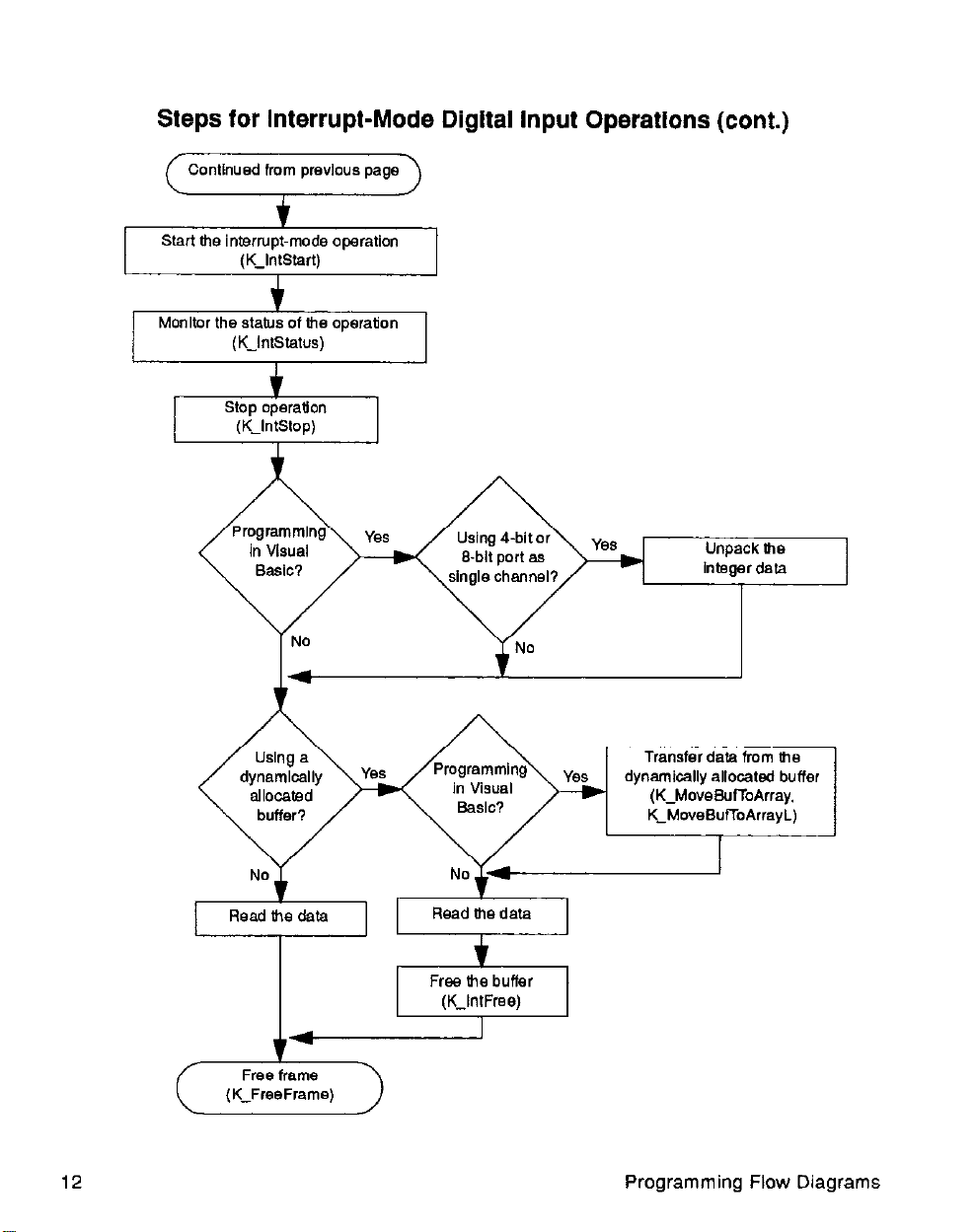
Steps for Interrupt-Mode Digital input Operations (cont.)
( Continued from previous page \
Start the interrupt-mode operation
*I
12
Transfer data from 618
dynamically allocated buffer
(K-MoveBuTToArray.
K~MoveSu~oArrayL)
Free frame
(K-FreeFrame)
Programming Flow Diagrams
Page 20

Steps for Interrupt-Mode Digital Output Operations
1 Dimension a local array
number of values to store In array
K-SetSufl for Visual Bask Integer arrays,
KKSetSufL for Visual Basic long arravs)
1
13
Page 21

Steps for Interrupt-Mode Digital Output Operations (cont.)
Continued from previous page
Load output values into
program’s local array
Load output values
into array 0, buffer
Transfer data to me
dynamically allocated buffer
(K~Mo”eA,,ay-k&f,
K-MoveA,,ayToBuR)
Start the interrupt-mode operation
rY&iF=+
Monitor the Matus of Gw operation
(I(-IntStatw)
14
Programming Flow Diagrams
Page 22
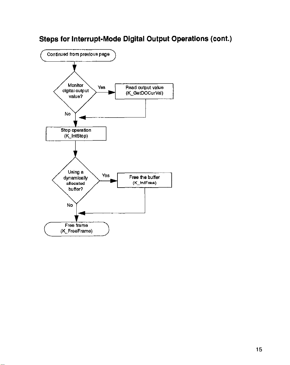
Steps for Interrupt-Mode Digital Output Operations (cont.)
( Contlnusd from previous page 1
Read cutput value
(K-GetDOCurVaJ)
stop operation
(K-IntStop)
15
Page 23
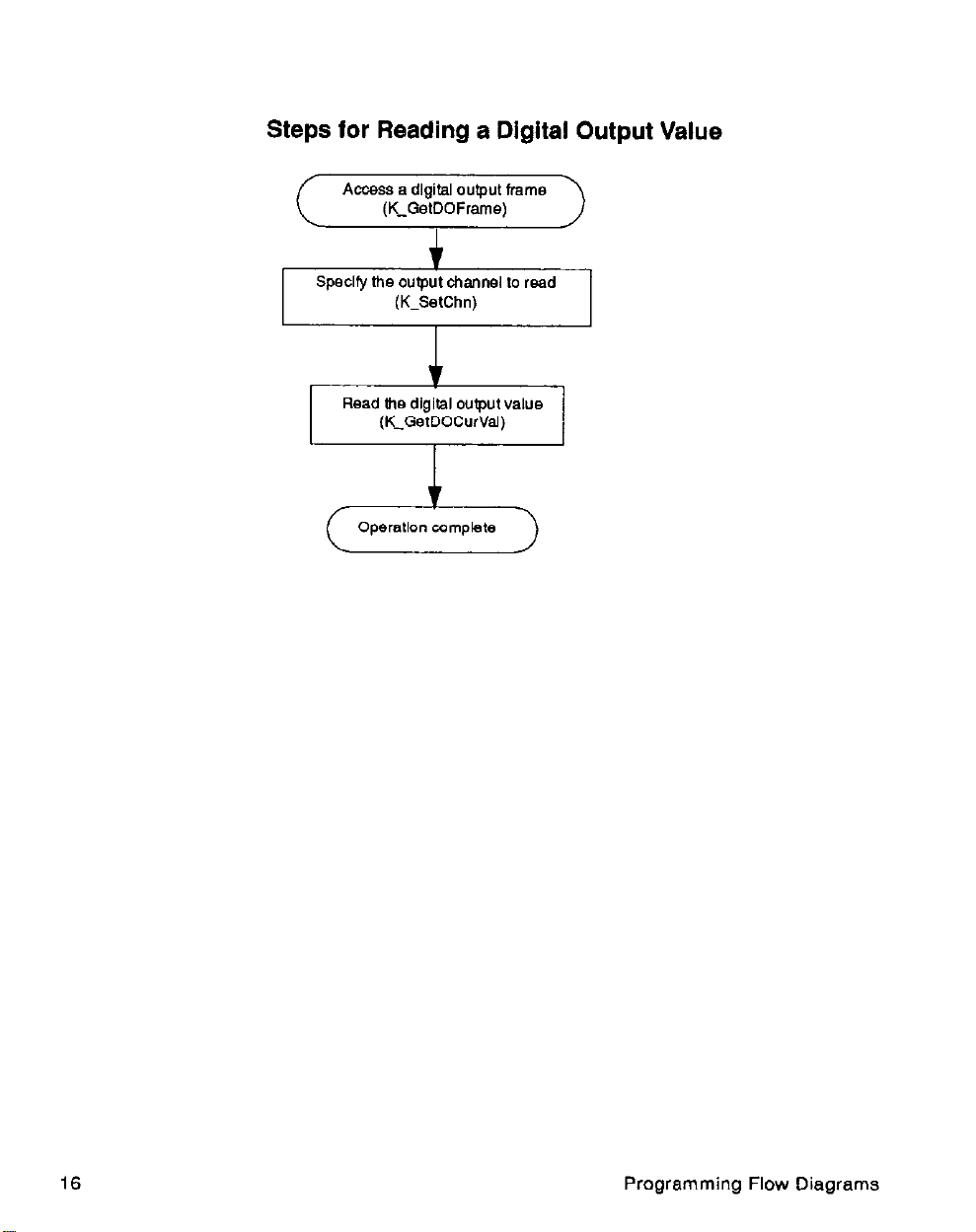
Steps for Reading a Dlgltal Output Value
16
Programming Flow Diagrams
Page 24
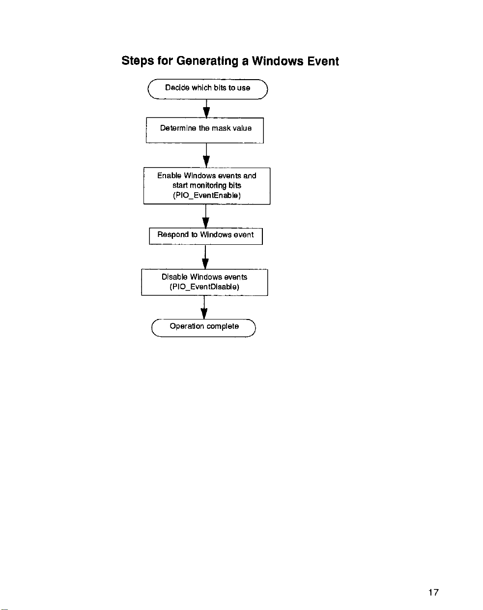
Steps for Generating a Windows Event
Enable Windows ewnts and
start monitoring bits
(PIO-EventEnable)
17
Page 25

 Loading...