

Page 1

ASO-ADC-16
User’s Guide
Revision A
Printed February, 1333
Parr No. 24460
0 Keithley Data Acquisition 1993
Page 2

WARNlNG WARNlNG
Keithley Data Acquisition assumes no liability for damages consequent to the Keithley Data Acquisition assumes no liability for damages consequent to the
use of this Product. This Product is not designed with components of a level use of this Product. This Product is not designed with components of a level
of reliability that is suitable for use in life support or critical applications. of reliability that is suitable for use in life support or critical applications.
The information contained in this manual is believed to be accurate and reliable.
However, Keithley Data Acquisition assumes no responsibility for its use; nor for
any infringements or patents or other rights of third parties that may result from
its use. No license is granted by implication or otherwise under any patent rights
of Keithley Data Acquisition.
Keithley Data Acquisition does not warrant that the Product will meet the
Customer’s requirements ot will operate in the combinations which may be
selected for use by the Customer or that the operation of the Program will be
uninterrupted or error free or that all Program defects will be corrected.
Keithley Data Acquisition does not and cannot warrant the performance or results
that may be obtained by using the Program. Accordingly, the Program and its
documentation ate sold “as is” without warranty as to their performance
merchantability, ot fitness for any particular purpose. The entire risk as to the
results and performance of the program is assumed by you.
All brand and product names mentioned in this manual are trademarks or
registered trademarks of their respective companies.
Reproduction or adaptation of any part of this documentation beyond that
permitted by Section 117 of the 1976 United States Copyright Act without
permission of Keirhley Data Acquisition is unlawful.
Keithley Data Acquisition l 440 Myles Standish Blvd. l Taunton, MA 02780
Telephone: (508) 880-3000 l Fax: (508) 880-0179
Page 3

Contents
Chapter 1
1.1
1.2
1.3
1.4
Chapter 2
2.1
2.2
2.3
2.4
2.5
Chapter 3
3.1
3.2
Introduction ............................. 1
About the ASO-ADC-I6 ............................ 1
Prerequisites .................................... 3
Getting additional help ............................. 3
Installing the AS0 ................................ 5
The Function CalI Driver .................... 7
Available operations ........................... ...
Overview of programming with the Function Call Driver ...... 9
General programming tasks ......................... 1 1
Operation-specific programming rasks .................. 11
Language-specific programming notes
............... ..
7
17
Callable Functions ........................ 25
Functional grouping .............................. 25
Function reference ...............................
29
Chapter 4
4.1
4.2
4.3
Chapter 5
5.1
5.2
Appendix A
Appendix B
File I/O Driver ..........................
Overview .....................................
Loading and unloading the driver ..................... 66
Language-specific programming notes
..................
65
65
70
Fiie I/O Commands ....................... 81
Functional grouping
Command reference ..............................
..............................
8 1
84
Function CaIl Driver error messages ............ 97
File I/O Command Driver error messages ......... 103
Page 4

.; ,f
Page 5

Introduction
About the ASO-ADC- 16
The ASO-ADC-16 is the Advanced Software Option (ASO) for the
ADC-16 analog input and digital l/O board. The AS0 includes a set of
software components that you can use, in conjunction with a programming
language, to create application programs that execute the operations
available on the ADC-16.
The two primary components of the AS0 are the Function Call Driver
and the File I/O Driver. These drivers represent two distinct methods of
providing your application program with high-level access to the
acquisition and control operations available on the ADC-16. The AS0 also
includes support files, example programs, and a configuration utility.
The Function Call Driver and the File I/O Driver are independent of each
other; your application program will use one or the other, but nor both.
The two drivers are implemented differently and provide slightly different
fmctionality. You should use whichever driver is appropriate for your
pt-ogramming skills and your application’s requirements.
Page 6

Function Call Driver
The Function Call Driver enables your program to define and execute
board operations via calls to dl-iver-provided ftmctions. For example, your
program can call the driver-provided K-ADRead fwcrion to execute a
single-point, A/D input operation.
The AS0 includes several different versions of the Function Call
Driver. The .LIB and .TPU versions are provided for DOS application
development. The Dynamic Link Library (DLL) is provided for Windows
application development.
The AS0 and this manual provide the necessary tools, example programs
and information to develop Function Call Driver programs in the
following languages:
. Borland C++ (version 2.0 and higher)
. Borland Turbo C (version 2.01)
. Borland Ttlrbo Pascal (version 6.0)
. Borland Turbo Pascal for Windows (version 1 .O)
. Microsoft C (version 5.1 and above)
w Microsoft Quick C for Windows (version 1 .O)
. Microsoft Visual Basic (version 1 .O and higher)
File I/O Driver
Thr File I/O Driver enables your program to define, execute, and retrieve
the results of board operations by writing (to the driver) dl-iver
-provided File I/O Commands. For example, your program can wire the
Read Channel 1 command to execute a single-point, A/D input operation.
You can use the File l/O Driver to create DOS applications with any
language that supports file l/O. The AS0 and this manual provide the
necessary tools, example programs and information to develop File I/O
Driver programs in the following languages:
. Interpreted BASIC
m QuickBASIC
. Borland Turbo C
. Borland Txbo Pascal
n
Microsoft C
. Microsoft Pascal
Page 7

-
1.2
Prerequisites
The AS0 is designed exclusively for use with the ADC-16. This manuzal
ass~unes that you understand the information presented in the ADC-I6
&r’s Guide. Additionally, you must complete the board installation and
configuratioo procedures outlined in the ADC-I6 lherl Grride before you
attempt any of the procedures described in this manual.
The fmdamental goal of this manual is to provide you with the
information you need to write ADC-I6 application programs that u.w the
AS0 drivers. It is recommended that you proceed through this manual
according to the sequence suggested by the table of contems; this
will minimize the amount of time and effort required to develop your
ASO-ADC-16 application programs.
-
1.3
Getting additional help
The following resources provide information about using the ASO:
.
this manual
.
the ADC-I6 lherk Gaide
. the AS0 example programs (these are copied to your system’s hard disk
during the installation procedure)
.
the documentation for the programming language you arc using
Call our Technical Support Department if you need additional auistance
A Technical Support Engineer will help you diagnose and solve your
problem over the telephone.
Keithley Data Acquisition - Technical Support
508-880-3000
Monday - Friday, 8
A.M. -
7 P.M.
Page 8

For the most efficient and IlelpfuJ assisraoce, please compile the following
information before calling our Technical Support Department:
Version
Invoice/Order #
ADC-16
STA-IX8
Computer
Serial #
Base address setting
A/D
fttll-scale setting
Number installed
Manufacturer
CPU type
Clock speed (MHz)
Math co-processor?
Amount of RAM
Video system
Language
i3.2768
8088 286 386
8 12 20 25 33
Yes No
CGA Het-c&s EGA VGA
V +5 V
486
Otllel-
0rhe1
4
ASO-A[)(::-16 User’s Guidr - Iicv. A
Manufacturer
Version
Page 9

1.4 Installing the AS0
-
The files on these AS0 distribution diskettes are in compressed format.
You must use the installation program included oo the diskettes to insraIl
the AS0 software. Since the aggregate size of the expanded AS0 files is
approxtmately 1 .O MB, check that there is at least this much space
available oo your PC’s hard disk before you attempt to install the ASO.
Perform the following procedure to install the AS0 software (note that it
is assumed that the floppy drive is designaced A:):
1. Make a back-up copy of the distribution diskette(s).
2. Insert AS0 diskette #l into the floppy drive
3. Type the following commands at the DOS prompt:
A: 1~1
install [LEn!e~r&/
The installation program prompts you for your iostallarion preferrnccs.
including the name of the directory into which the AS0 files will br
copied. The installation program expands the files on the AS0 diskette(s)
and copies them into the directory you specified; refer to the IiIe
FIl.ES.IXK: in the AS0 installation directory for the names and
descriptions of these files.
Page 10

Page 11

The Function Call Driver
2.1 Available operations
The Function Call Driver provides functions through which an application
program can perform the following operations:
Immediateexecution operations
. Single-value A/D input
. Single-value digital input
n Single-value digital output
Frame-based operations
H Multi-value, interrupt-mode A/D iuput
n
Multi-value, synchronous-mode A/D input
immediate-execution
operations
Immediate-execution operations and frame-based operations are described
in the following subsections.
The three immediate-execution operations and the Callable Function
associated with each are as follows:
l
Single-value A/D input:
. Single-value dig&al input:
l
Single-value digital output: K_DOWrite
K_&DRead
K-DIRead
The calling arguments for these functions define the attributes of the
associated operation. Upon receipt of a call to one of these hmctions. the
driver immediately executes the associated operation.
(:hapter 2 - The t;unction (:all I)rivcr
7
Page 12

Frame-based
operations
The two frame-based operations and the Callable Function associated wirb
each are as follows:
. Multi-value, interrupt-mode A/D input: K-IntStart
.
Multi-value, synchronous-mode A/D input: K-SyncStart
The description of frame-based operations requires the introduction of a
few new terms.
Afiume is a data structure whose elements correspond ro the defining
attributes of a board operation. The driver
L~S
two different types of
frames: A/D and Digital Output frames. The driver mainrains a pool of
four A/D frames and four Digital Output frames.
The values of a frame’s elements define the operation? attributes. For
example, the elements contained in an A/D frame al-e as follows:
n
Srdrt
Channel - defines the first channel in a
n
Stop Channel - defines the last channel in a scan
scan
. Gain element - defines the gain applied to all channels in the scan
The driver provides fimctions that set the value of one or more elements.
For example,
K-SetG
sets the value of a frame’s Gain elemeot, and
K_SetStarxStopChn sets the values of a frame’s Start Channel and Stop
Channel elements.
Page 13

A jmm handle is a variable whose
value
identifies a frame. The sole
purpose of a frame handle is to provide a mechanism through which
different function calls can reference the same frame.
A device handle is a variable whose value identifies an insrdlled board. The
sole
purpose
of a device handle is to provide a mechanism through whirl
different fitnction calls can reference the same board.
A frame-based operation is so-called because the function that pcrfol-ms the
ape!-atmn
uses
a frame handle as its single calling argument. The
frdrnr
handle identifies a frame whose element values are the operation’s
attributes. The values of all of a frame’s elements must be set brfore that
frame’s handle can be used as a calling argument to a funcrion that
exccutcs a frame-based operation.
2.2 Overview of programming with the Function Call Driver
The procedure to write a Function Call Driver program is a& followx
1. Define the application’s requirements.
Defining the
application’s
requirements
2. Write the program code.
3. Compile and link the
program.
The subsections that follow describe the details of each of these wps.
Before
you
begin writing the program code. you should have a char idea
of the board operations you expect your program to execute. Additionally.
you should determine the sequence in which these operations must be
executed and the characteristics (number of channels, gains. and ho on)
that define each operation.
You
may find it helpful to review the list of
available operations in Section 2. I and to browse through the short
descriptions of the Callable Functions in Section 3. I.
Page 14

Writing the
program code
Several so~~rces of information relate to this step:
. Section 2.3 explains the programming tasks that are common to all
Function Call Driver programs
. Section 2.4 describes the sequence of function calls requil-ed to execute
each of the available operations
. Section 3.2 provides detailed information on individual fimctions
. The AS0 includes several example source code files for Function Call
Driver programs. The FILIXIXK file in the AS0 installation directory
lists and describes the example programs.
The phrase ycneralprogrumming tasks, as it is used in this chapter, refers to
the programming tasks that every Function Call Driver program must
execute. The task of obtaining a device handle, for example, qualifies as a
general programming task, since the sequence of function calls required to
execute any of the available board operations includes at least one f&tion
whose calling arguments include a device handle. Section 2.3 provides the
details of the general-programming tasks.
Each available operation also has an associated set of tasks that the
program must perform to execute the operation; these are referred to as
operation-specific programming tasks. Section 2.4 provides the derails of the
operarlon-specific programming tasks for each available operation.
Compiling and linking
the program
Refer to Section 2.5 for compile and link instructions and other language-
specific considerations for each supported language.
Page 15

- 2.3
General programming tasks
Every Function Call Driver program must execute the following
programming tasks:
I. Identify a function/variable type definition file
The method to identify this file is language-specific; refer to Section 2.5
for addirional information.
2. Declare/initialize program variables
3. Call ADCl6-DevOpen to initialize the driver
4. Call ADClb-GetDevHandle to initialize the board and get a device
handle for the board
The tasks listed are the minimum rasks your program must complete
before it attempts to execute any operarion-specific tasks. Your application
may require additional general-progralnmiIlg tasks. For example, if your
program requires access to two boards, then it mwst call
ADCl6_GetDevHandle for each board.
2.4
-
Operation-specific programming tasks
This section describes the set of programming casks char your program
must perform to execute the following operations:
n
Single-value A/D input
n
Single-value digital input
. Single-value digital output
. Interrupt-mode A/D input using channel-gain array
. Synchronous-mode A/D input using channel-gain array
n
Interrupt-mode A/D input using start/stop channels
. SynchronoLts-mode A/D input using start/srop channels
The set of tasks listed for each operation are valid only if the application
program has already completed the general-programmitlg tasks.
Page 16

Single-value A/D input
To execute a single-value A/D input, your program musr call K-ADRead.
The calling arguments identify the board that executes the operation, the
channel on which the value is acquired, the gain applied to that channel,
and the buffer in which the value is stored.
Single-value digital input
To execute a single-value digital input, your program must call K_DIRead.
The calling arguments identify the board that executes the operation, the
channel on which the value is acquired, and the buffer in which the value
is stored.
Single-value digital output
To execute a singk-value digital output, your program must
call
K-DOW&. The calling arguments identify the boa!-d that executes the
operation, the channel on which the value is written, and the buffer f+om
which the value is written.
12
AS0ALX-I 6 User’s Guide - Kev. A
Page 17

Interrupt-mode A/D input using start/stop channels
Your program must perform the following tasks to execute an interrupr-
mode A/D input operarion whose channel-scanning sequencr is given by
the sequence’s start and srop cl~annels:
1.
Allocate a buffer in which rhe driver stores the A/D values. Use
K~INTAlloc if you want to allocate this buffer outside the program’s
memory area (you must use K_INTAlloc if you are writing an application
that will execute in Windows standard mode).
2.
Call
K-GetADFtame
3.
Call K-SetBuf’to assign the buffer address obtained io stt=p I to the Ruffer
Address element in the frame associated with [he frame hat& obtained in
srep 2.
4.
Call
K-SecStartStopG
to the Start Channel, Srop Channel, and Gain elemenu in the frame
associated with the frame handle obtained in step 2.
Call
5.
K-INTStart
to get the handle to an A/D frame
or
K-SetStztStopChn and K-SetG
to start the operation.
to
assign
values
6.
Call
K-INTStatus
(Optional for C and Pascal programs)
7.
Call
K-MoveDataBuf
user-defined array.
8.
If
K-INTAlloc was
deallocate the buffer.
Call
9.
K-FreeFrame
from srep 2) to the pool of available frames.
to monitor the status of the operation,
to transfer the acquired data from the buffer to a
used to allocate a buffer io step
to return the frame (associated with the frame handle
1,
call
KPINTFree to
Chapter 2 - ‘l‘hc Function (31 l)rivcr
13
Page 18

Interrupt-mode A/D input using channel-gain array
Your program must perform the following tasks ro execute an interrupt-
mode A/D input operation whose cllannel-scannitl~ sequence is given by a
channel-gain array:
1.
Define and assign values to a channel-gain array. The format and other
information pertaining to channel-gain arrays is listed tmder the reference
entry for K-SetChnGAry on page 60.
2. Allocate a buffer in which the driver stores the A/D values. Use
K_INTAlloc if you want to allocate this buffer outside the program’s
memory area (you must use K-INTAlloc if you are writing an application
that will execute in Windows standard mode).
3. Call K-GetADFrame to get the handle to an A/D frame.
4. Call K_SetBufto assign the buffer address obtained in step 2 to the Buffet
Address element in the frame associated with the frame handle obtained in
step 3.
5. Call K_SerChnGAry to assign the channel-gain array from step 1 to the
Channel-Gain Array Address element in the frame associated with the
frame handle obtained in step 3.
6. Call K-INTStart to start the operation
7. Call K-INTStatus to monitor the stattts of the operation,
8. (Optional for C and Pascal programs)
Call K_MoveDaraBuf to transfer the acquired data from the buffer to a
user-defined array.
9. If K-INTAIIoc was used to allocate a buffer in step 2, call K-INTFree to
deallocate the buffer.
10. Call K-FreeFrame to return the frame (associated with the frame handle
from step 3) to the pool of available frames.
Page 19

Synchronous-mode A/D input using start/stop channels
Your program must perform the following tasks to execute a synchronou+
mode A/D input operation whose channel-scanning sequencr i\ given by
the sequence’s start and stop channels:
1, Allocate a buffer in which the driver stores the A/D values. Usr
K-INTAlloc if you want to allocate this buffer outside the program’\
memory area.
Call K-GetADFrame to get the handle to an A/D frame.
2.
3. Call K_SetBuf to assign the buffer address obtained in step 1 to the Rufft-r
Address element in the frame associated with the frame handle obtained in
step 2.
4. Call K_SetSrartStopG or K~SetStarrStopChn and K_SetG to assign valurs
to the Starr Channel, Stop Channel, and Gain elements io the frame
associated with the frame handle obtained in step 2.
5. Call K-Sync&art to start the operation.
6. (Optional for C and Pascal programs)
Call K-MoveDataBuf to transfer the acquired data from the buffer to a
user-defined array.
7. If K-INTAIloc was used to allocate a buffer in step 1, call K_INTFree to
deallocate the buffer.
8. Call K_FreeFrame to return the frame (associated with the frame handlr
from step 2) to the pool of available frames.
Page 20

Synchronous-mode A/D input using channel-gain array
Your program must perform the following tasks to execute a sy~~l~ronous-
mode A/D input operation whose channel-scanning sequence is given by a
channel-gain array:
Define and assign values to a channel-gain array. The format and other
1.
information pertaining to channel-gain arrays is listed under the reference
entry for K-SetChnGAry oo page 60.
2.
Allocate
K~lNTAlloc if you want to allocate this buffer outside the program’s
memory area.
3. Call K-GetADFrame to get the handle to an A/D frame.
4. Call K-SetBufto ass@ the buffer address obtained in step 2 to the Buffer
Address element in the frame associated with the frame handle obtained in
step 3.
5. Call K_SetChnGAry to assign the channel-gain array from step 1 to the
Channel-Gain Array Address element in the frame associated with the
frame handle obtained in step 3.
a buffer in which the driver stores the A/D values. Use
6. Call K_SyncStart to start the operation.
7. (Optional for C and Pascal programs)
Call K-MoveDataBuf to transfer the acquired data from the buffer to a
user-defined array.
8. If K~INTAUoc was used to allocate a buffer in step 1, call KPINTFree to
deallocate the buffer.
3. Call K-FreeFrame to return the fi-ame (associated with the frame handle
from step 3) to the pool of available frames.
Page 21

2.5 language-specific programming notes
This section provides specific programming guidelines for each of the
supported languages. Additional programming information is available in
the AS0 example programs. Refer to the FILES.DOC tile for names and
descriptions of the AS0 example programs.
Borland C++, Microsoft C and Borland Turbo C
Related files
Compile and link
instructions
ADCI6.LIB
DASRFACE.LIB
USERPROTH
Borland C++:
BCC -c -ml fi1ename.c
TLINK c0l+filename,filename..adcl6+dasrface+cl:
Microsoft C:
CL /AL /c fi1ename.c
LINK filename.,,ADC16+DASRFACE:
Turbo C:
TCC -c -ml fi1ename.c
TLINK cOl+filename,filename..adcl6+dasrface+cl:
Page 22

Example program
Execute a single A/D conversion
I* C include files *I
#include "8tdio.h"
i/include "std1ib.h"
I* ADC-16 driver include file i/
#include "userprot.h"
I* Local variables *I
DOH AOC16;
char NumOfBoards:
int Err:
long Advalue:
I* Begin main module "I
main0
t
I* Initialize the hardware/software 'I
if (( Err = ADC16-DevOpen( "ADC16.CFG", &NumofBoards )) !=OJ
t
putch (7); printf(
exit(Err1:
I
I* Establish communication with the driver .&I
I* through a device handle *I
if ( ( Err = ADC16-GetDevHandle( 0, &ADClG ) 1 != 0 1
i
putch (7): printf("Error %X during GetDevHandle ".Err);
exit(Err):
1
I* Read channel 0 at gain 1: store sample in Advalue *I
if ((Err = KmALlRead (ADC16, 0, 0, &ADvalue)) != 0)
1
putch(7): printf ("Error %X in Km~ADRead operation ", Err):
exit(Err);
I
' Error %X during DevOpen ', Err 1:
I" Device Handle *I
/* #boards in AOC16.CFG */
I' Function ret err flag *I
I* Storage for A/D value *I
I* Display ADvalue *I
printf ("A/D value from channel 0 is : %x\n". ADvalue):
I
Page 23

Borland C++
If you want to compile a Borland C++ program as a standard C program.
refer to the information presented in the previous section. If you want to
compile your program as a Borland C++ program, refer to the informarion
presented in the previous section with the following exceprions:
1.
Use the supplied file USERPROTBCP instead of USERPR0T.H.
2. Specify the C++ compilation in one of the following two way\:
a. Specify .CPP as the extension for your source file, or
b. Use the BCC 4’ command line swirch.
Borland Turbo Pascal
Compile and link
instructions
Example program
TPC ,filename.pas
Execute a single A/D conversion
Program TPEXAMPLE;
[ UNITS USED BY THIS PROGRAM I
Uses Crt. ADC16:
I LOCAL VARIABLES I
Var
Devhandle : Longint: I Device Handle I
ConfigFile : String; I String to hold name of configuration file j
NumOfBoards : Integer:
BoardNumber :
Ertn : Word; I Error flag 1
Gain : Byte; I Overall gain 1
ADvalue : Longint; I Holds A/D sample I
Chan : Byte: ( A/D channel I
( BEGIN MAIN MODULE I
BEGIN
I STEP 1: This step is mandatory: it initializes the
internal data tables according to the information
contained in the configuration file ADCI6.CFG.
I
ConfigFile := 'ADC16.CFG' + #O:
Ertn := ADC16~DevOpen( ConfigFile[ll. NumOfEoards 1:
IF Ertn 0 0 THEN
BEGIN
writeln( 'Error ', Ertn. 'an Device open' ):
Halt(l):
END:
( STEP 2: This step is mandatory: it establishes
communication with the driver through the
Device Handle.
I
Integer:
(hapter
2
- 'The hnction (:all Ikiver
19
Page 24

BoardNumber := 0:
Ertn := ADCl66GetOevHandle( BoardNumber. Devhandle 1;
IF Ertn 0 0 THEN
BEGIN
writeln( 'Error ', Ertn. getting Device Handle' 1:
Halt(l):
END;
{ STEP 3: Read A/D sample from channel 0 at gain 1
(Gain Code 0) and store in local variable.
J
Chan := 0:
Gain := 0;
Ertn := KmADReadCDevhandle. Chap, Gain, ADvalue):
IF Ertn 0 0 THEN
BEGIN
writelnC^G. 'Error ii '.Ertn,
Halt(l):
END:
writeln('A/D VALUE : ', ADvalue):
END.
'Occurred during KKADRead call');
Borland Turbo Pascal for Windows
Related files
NOkS
ADCI6TPW.INC
ADCl6.DLL
If you use ADCI G.DLL, the information presented for Borland Turbo
Pascal applies here with the following additions:
n
Use the compiler directive ($1 ,,. } to include the supplied includr file
ADCl6TPW:INC.
. Substitute ‘Wit&-t for the ‘Crt’ unit; this is necessary in order that the
console 1/O procedures (writeln, readln, etc...) operate properly.
The following code fragment illustrates these additions:
Program TPW.~EX:
{ UNITS USED BY THIS PROGRAM 1
Uses WinCrt:
'1 LOCAL VARIABLES I
Var
1 ADC16 function prototypes that reference .OLL 1
($1 ADC16TPW.INCI
( BEGIN MAIN MODULE 1
BEGIN
20
ASO-AD(::-16 L&r’s Guide - liev. A
Page 25

If you use ADCl GTPW.INC, the information presented for Bol-land
Turbo Pascal applies here with the following exceptions:
n
Substitute ADCl6TPW.INC for the ADCIG unit.
- Substitute ‘WinCrt’ for the ‘Or unit: this is necessary in order that the
console 110 procedures (w&In. readln, etc...) operate properly.
The following code fragment illustrates these substitutions:
Program TPW-EX;
I UNITS USED BY THIS PROGRAM I
Uses WinCrt. ADC16TPW:
'I LOCAL VARIABLES I
yar
I BEGIN MAIN MODULE I
BEGIN
Microsoft Quick C for Windows
Related files
Compile and Link
instructions
Notes
ADCl6.DLL
1. Load fi&une.c into the Quick C for Windows environment
2.
Create a project file.
3. Select PI<OJE~:I’ c BUII,L) to create a stand-alone .EXF. that can br
executed from within Windows.
The programming procedure required to call the Callable Functions from
Quick C for Windows programs is identical to the procedure described for
Microsoft C.
(hpter 2 - 'l'he Funcri<rn (:all Ihivcr
21
Page 26

Microsoft Visual Basic for Windows
Related files
Notes
ADClG.DLL
ADClGEX.BAS
Before you begin coding your Visual Basic proogrm~, you must copy (from
inside the Visual Basic environment) the contents of ADClGEX.BAS into
your application’s GLOBAL.BAS. Use the following procedure to add the
contents of ADCl6EX.BAS to GLOBAL.BAS (you should make a back-up
copy of GLOBAL.BAS before you modify it):
1. Select FILE h Arm FILE... from the Viswl Basic main menu.
2. Select ADClGEX.BAS.
3. Highlight the contents of the entire ADC16EX.BAS file.
4. Select
Windows clipboard.
5. Double-click on GLORALRAS in the Project window.
6.
Select Erm b PASTE.
7.
S&XX FIII h SAVE PKOIEC:T.
Em
b COPY to
COPY
the Comm of ADClGEX.BAS to the
22
AS0AM:- I6 User’s (;uidr - Kcv. A
Page 27

Example program
Execute a single A/D conversion.
Sub CommandlLClick 0
board% = 0
Cls
For x = 0 to 9' Clear our buffer
Ibuffer = 0
Next x
MyErr = ADC16~~~devopen("..\ADC16.CFG". board%)
If MyErr 0 0 Then
MsgBox "ADCIG~~mdevopen Error", 48. "Error'
GoTo exyl
End If
Print
Print "Scanning Channels ': strtch: "-': stpch
MyErr = ADClbLgetdevhandle(0. adcl6)
If MyErr <> 0 Then
MsgBox "ADCl6mgetdevhandle Error", 48. "Error"
GoTo exyl
End If
Print
Print "AD Data :*
Print
For x = strtch to stpch
MyErr = K.-ADRead(adcl6. x. Chgain. retval)
lBuffer(x) = retval
Print '
Next x
Print
Print
exyl:
End Sub
Channel -; x; - = -; HexB(lBuffer(x))
Page 28

Page 29

3.1
Callable Functions
3
Functional grouping
The Callable Functions can be classified according to the f~mctionality that
each provides. This secriot~ lists each Callable Function as a mrmbcr of
one of the following groups:
n
Initialization
n
Memory management
n
Frame management
n Frame-element management
m Frame-based operation comol
. Immcdiatc-execution operations
. Miscellaneous operations
This section provides short descriptions of each function; refer to Srction
3.2 for additional information on each function.
Initialization
ADCl b_DevOpen
ADCl 6&GetDevHandle
K-DASDevInit
Initialize and configure the driver.
Obrain a device handle.
Reset and initialize the device and driver.
Page 30

Memory management
K_lntAlloc
Allocate a buffer suitable for an interruptmode A/D operation.
K-IntFree
De-allocate an interrupt buffer that was
previously allocated with K~lnrAlloc.
K-MoveDataBuf
Transfer acquired A/D samples between a
menmy buffer and an array.
Frame management
K_FreeFrame
K-GetADFrame Obtain the handle to an A/D frame.
K_GetDOFrame Obtain the handle to a digital output
Free the memory used by a frame and
return the frame it to the pool of
available frames.
frame.
Frame-element management
KPClearFrame
K-GetBuf Get the values of an A/D frame’s Buffer
K-GetChn
K-GetChnGAry
K-GetDOCurVal
Set all the elelnelm Of aI1 A/D frdIIle t0
their default values.
Address and Number of Samples
elements.
Get the value of an A/D frame’s Start
Channel element.
Get the value of an A/D frame’s
Channel-Gain Array Address element,
Get the value of a digital output frame’s
Digital Output Value element.
Page 31

Frame-element management (cont’d)
K_GetG
K-GetStartStopChn
K_GetStartStopG
K-InitFrame
K-SetBuf
K-SetChn
K-SetChnGAry
Get the value of an A/D frame’s Gain
Code element.
Get the values of an A/D frame’s Srart
Channel and Stop Cbannet ete~nenr\.
Get the values of an A/D frame‘> Srarr
Channel, Srop Channel. and Gain Code
etenw1ts.
Initialize a board’s A/D circuitry and >CI
an A/D frame’s elements to their default
YdlweS.
Set the values of an A/D frame’s Huff&
Address and Number of Samples
elements.
Set the value of an A/D frame’s Srarr
Channel etemenr.
Set the value of a
frame’s
Channel-Gain
Array Address element.
K_SetG
K_SetStartStopChn
K-SerStartStopG
Set fbe value of a11 A/D
frdIlW’~ Gdill
Code element.
Set the VatLIes Of all A/D
frdllle’s Srdrt
Channel and Stop Channel elements.
Set the vatues of an A/D fi-ame’s Start
Channel, Stop Channel, and Gain Code
elements.
Page 32
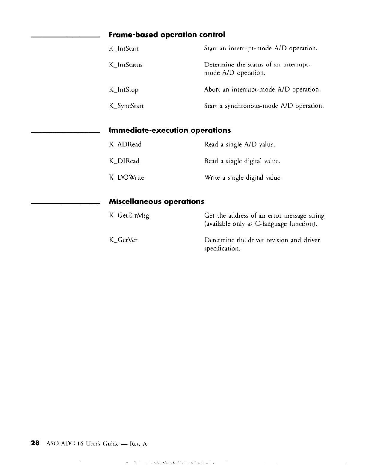
Frame-based operation control
K_IntStart
K-IntStatus
K-IntStop
KpSync.‘%drt
Start an interrupt-mode A/D operation.
Determine the srdtus of an interrupt-
mode A/D operation.
Abort an interrupt-mode A/D operation.
Start a synchronous-mode A/D operation.
Immediate-execution operations
K-ADRead
K_DIRead
KPDOWrite
Read a single A/D value.
Read a single digital value.
Write a single digital value.
Miscellaneous operations
KPGetErrMsg
Get the address of an error message string
(available only as C-language function).
K-GetVer
Detemine the driver revision and drivel
specification.
Page 33

3.2 Function reference
This section contains reference entries for the Callable Functions. Tbc
entries appear one pet page and in ascending alphabetical order (by
function name). These reference entries provide the derails associated with
the use of each function.
This section is not a good resource for general and conceptual information
about writing Function Call Driver programs. Moreover, much of tlw
information presented here requites a thorough understanding of the
concepts presented in Chapter 2. Do not ncprct to write n Function Cdl
Driver program merely, by consthing the
expect to u*c in yore program.
The info!-mation related to the following topics pertains to srvcral Caltabtr
Functions:
.
the format of A/D values and the procedure to determine the votragr
that produced a specific A/D value
.
the gain codes the driver mes to represent gains and the A/D input
ranges that correspond to each gain
.
the teturn value for every call to a Callable Function
reference
entries
for the jurcriom yorr
A/D values and
corresponding
voltages
These topics are described in the neyt several paragraphs and referred to
throughout the reference entries that follow.
There are thtee Callable Functions through which your program cau
acquire A/D values: K-ADRead, K-IntStart, and K_SyncStart. Although
the method to create/assign a storage buffer for the acquired value(s) is
different for each of these functiotls, they all state the A/D value in the
same format. Consequently, the interpretation of the A/D data is the same
regatdtess of the function with which it was acquired.
The driver configuration file specifies two attributes that affect how you
should interpret A/D values: the A/D Number Type and the A/D Full
Scale Range. The possible values for these attributes are as follows:
. A/D Number Type: Sign/Magnitude or 2i Complement
. A/D Full Scale Range: ~3.2767 VOF +5.0 V
Page 34
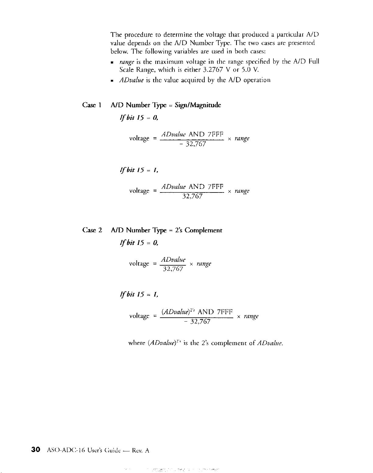
The procedure to determine the voltage that produced a particular A/D
value depends on the A/D Number Type. The two cases are presented
below. The following variables are used in botlr cases:
n
nzngc is the maximum voltage in the range specified by the A/D Full
Scale Range, which is either 3.2767 V or 5.0 V.
. ADvalue is the value acquired by the A/D operation
Case 1 A/D Number Type = Sign/Magnitude
If
bit 15 = 0,
volrdge =
If
bit 15 = I,
volrage =
Cave 2 A/D Number Type = 2’s Complement
If
bit 15 = 0,
voltage =
If
bit 15 = I,
ADvalue AND 7FFF
- 32,767
ADvalue AND 7FFF
32,767
ADvalue
32,767
x range
x range
x range
voltage = (ADuah& AND 7FFF
- 32,767
x range
Page 35

Gain codes
The Function Call Driver uses gain codes to indicate gains. The valid gain
codes are 0, 1, 2. The table below lists the gain that corresponds to rach
gain code. Additionally, this table shows the A/D input range for both
settings of the A/D Full Scale Range (the A/D Full SC& Range is qxcificd
by the driver configuration file).
gain
code
0 1
1
2
gain
10 i327.67 mV *500 mv
100
A/D input range for A/D input range for
1-3.2767
lidI-scale range
*3.2767 V
i32.767 mV *50 mv
V
*5.0 v
full-scale range
+5 v
Every call to a Callable Function returns an integer-type (16.bir) mum
value. A return value of 0 indicates that the function executed sutrrs~t%lly;
a non-zero return value indicates an error. The non-zero return values
correspond to error codes; these error codes and their corresponding rrron
are listed in Appendix A. Your program should always check a funcrion
cdtt’s
return
vdlur
and,
in rtle
case of an error, perfort an appropriate
action.
Page 36

ADC 16-DevOpen
Purpose
Prototype
Notes
Initialize and configure the driver.
C
DASErr far Pascal ADCl6_DevOpen( char far * cJsFlt,
char far * numDevices );
Pascal
Function ADC16PDevOpen( Var c&File : char;
Var numDevicer : Integer ) : Word;
Visual Basic for Windows
ADCIGPDevOpen Lib “ADClG.dll” (ByVal c&Filt$,
numDevices As Integer) As Integer
c&File
numDevices Number of devices defined in c&File. Valid values: 1, 2
ADCl6-DevOpen initializes the driver according to the information in cfKFile.
On return, numDevices contains the number of devices for which &File conrains
configuratioo information.
Driver configuration file
ADCl6~DevOpen writes a zero value to OPO and OPl; this turns off the
ADC-16’s r-&y 0 and relay 1.
Specify -1 for c&Fib to set the driver to its default configuration;
configuration specifies that the device is set as follows:
Board number 0 1
Board name ADC16
Base address 300 Hex
Range i3.2767 V
A/D Number Type SignMagnitude
Interrupt level AHex
Illstalled
STA-EX8s 0
ADC16
308 Hex
+3.2767 V
SignMagnitude
F Hex
0
the default
Page 37
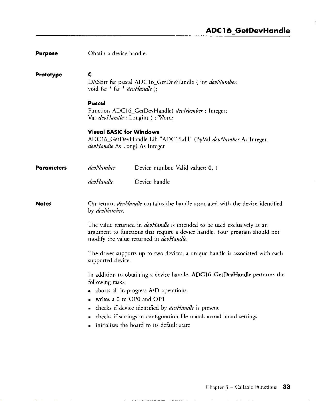
ADC 16-GetDevHandle
Purpose
Obtain a device handle.
Prototype C
DASErr far Pascal ADClb-GetDevHandle ( int dtvNumber,
void far * far * &Handle );
Function ADCl6_GetDevHandle( devNwnber : Inreger;
Var devHandle : Longint ) : Word;
Visual BASIC for Windows
ADCl G_GetDevHandle Lib “ADClb.dll” (ByVal devilirmrber As Integer.
devHandle As Long) As Integer
Parameters
Notes
deuNwnber
d&Handle
On
by &vNmber.
return,
Device number. Valid values: 0, 1
Device handle
devHandle contains the handle associated with the device identified
The value returned in deoHandle is intended to be used exclusively as an
argument to functions that require a device handle. Your program should not
modify the value returned in &Handle.
The driver supports up to two devices: a unique handle is associated wirh each
supported device.
In addition to obtaining a device handle, ADClb-GetDevHandle performs the
following tasks:
.
aborts all in-progress A/D operations
n
writes a 0 to OF0 and OPl
.
checks if device identified by deuHandle is present
.
checks if settings in configuration file match actual board settings
.
initializes the board to its default state
Page 38

K-ADRead
Purpose
Read a single A/D value.
Prototype C
DASErr fat pascal K-ADRead( DDH devHandle, unsigned chat &an,
unsigned chat gain&de, void far * ADvalue );
Pascal
Function K_ADRead( devHandle : Longint; than : Byte:
gaincode : Byte; Vat ADvalue : Longint ) : Word;
Visual BASIC for Windows
K_ADRead Lib “ADCl6.dll” (ByVal devHandle As Long, ByVal cban As Integer,
ByVal gainCode As Integer, ADvalue As Long) As Integer
Parameters
devHandle Handle to acquisition device
than Input channel. Valid values: 0,
gainCode Gain code. Valid values: 0 = lx, I = 10x, 2 = 100x
number of connected STA-EXS.
l,..., 7(m+l), where
m is the
Notes
ADvalue Storage location of acquired A/D value
On mum, ADvalue contains the value read from channel cl/an (at thr gain
indicated by gain code) of the device identified by devHandle.
See page 29 for the procedute to detetmine the voltage that produced the value
returned in ADvalue.
See page 31 for the A/D voltage ranges that cortespond to each gain.
34
AS0AD(I;- I6 User’s (:;uide - Rev. A
Page 39
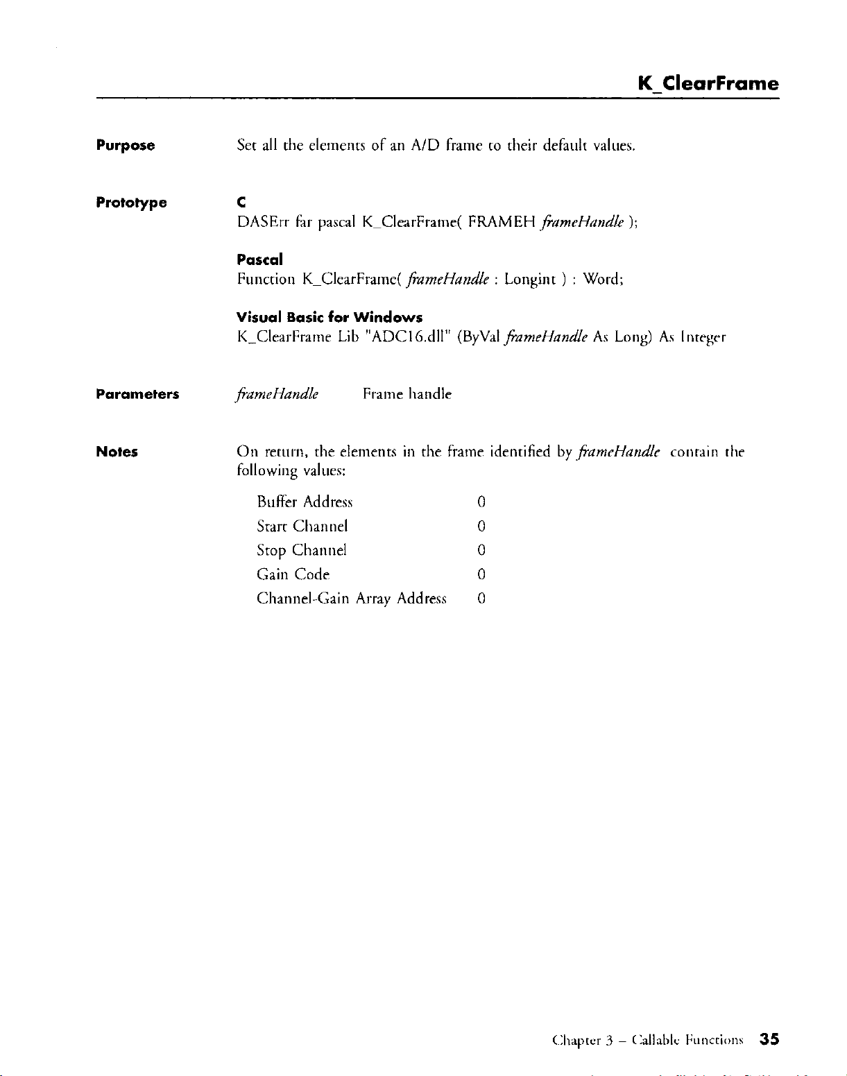
K ClearFrame
Purpose
Set all the elements of an A/D frame to their default values.
Prototype C
DASErr far Pascal KPClearFrame( FRAMEH @ameHarrdk );
Pascal
Function K_ClearFrame( flameHandle : Longint ) : Word;
Visual Basic for Windows
K_CleatFrame Lib “ADCl6.dII”
Parameters
Notes
j?ameHandle Frame handle
On retutn, the elements in the frame identified by frameHandle contain the
following values:
(Byvdl
Buffet Address
Start Channel 0
0
/FameHandle As Long) As lntegrt
Stop Channel 0
Gain Code 0
Channel-Gain Array Address 0
Page 40
Purpose
Reset and initialize the device and dtiver.
Prototype
Parameters
Notes
C
DASErr far Pascal KPDASDevlnit( DDH devHandle );
Pascal
Ftmction K-DASDevlnit( devHandle : Longint ) : Word;
Visual BASIC for Windows
KPDASDevlnit Lib “ADClG.dll” (ByVal ahHandle As Long)
As Integer
devHandle Device handle
K_DASDevInit pet-forms the following tasks:
. Aborts all in-progress A/D operations
. Wtites a 0 to 01’0 and OPl
. Checks if device identified by devHandle is present
. Checks if settings in configuration file match actual board settings
. loitializes the board to its defaLllt state
AS0AlX- I6 User’s (;uide - Rev. A
36
Page 41

KpDlRead
Purpose
Prototype
Parameters
Read a single digital value.
C
DASErr far pascal K_DIRead( DDH deuHandk, unsigned char chnn.
void far * Dlualr~c );
Pascal
Function K_DIRead( devHandle : Longint; than : Byte;
Var D/value : Longint ) : Word;
Visual Basic for Windows
K-DIRead Lib “ADClG.dII” (ByVal devHandle As Long,
ByVal than As Integer, Dlvnl~le As Long) As Integer
deuHandle
chan
Dlualue
Device handle
Digital inpur channel. Valid value: 0
Digital input value. Valid values: 0, 1, 2, 3
Notes
On return, D/value contains the digital value read from cbannrl c/ma of rbr
device identified by &uHandle.
D/value is a 32-bit variable. The acquired digital value is stored in bits 0 and I:
the values in the remaining bits of DIvaLle are not well-defined. Tbr figure
below illustrates the format of D/value.
Page 42

K DOWrite
Purpose
Prototype
Parameters
Write a single digital value.
C
DASErr far pascal K-DOWrite( DDH deuHandle, unsigned char chun,
long DOvalue );
Pascal
Function K-DOWrite( devHandle : Longint; than : Byte;,
DOvalue : Longint ) : Word;
Visual Basic for Windows
K_DOWrite Lib “ADCl6.dII” (ByVal devHundle As Long,
ByVal than As Integer, ByVal DOvalue As Long) As Integer
devHandle Device handle
than
DOvalue
Digiral output channel. Valid value: 0
Digital output value. Valid values: 0, l,..., 31
Notes
K-DOWrite outputs the value in DOvalue to channel cban on the device
identified by deuHandle
DOvalue is a 32-bit variable; the significance of the bits in DOvalue depeods on
if there is a connection between the board and an STA-EX8:
If
the board is not connected to an STA-EM:
The output value comprises the values in bits 0 - 4; the values in bits 5 31
are not significant. This format is illustrated in the following figute:
If
the board is connected to me or more STA-EX8:
The output value comprises the values in bits 0 and 1; the values in bits
2 - 31 are not significant. This format is illustrated in the following figure:
Page 43

K-FreeFrame
Purpose
Free rhe memory used by a frame and return the frame it to rhe pool of available
frames.
Prototype C
DASErr far Pascal K_FreeFrame( FRAMEH j%meHandle ):
Pascal
Fun&on K-FreeFrame( fiameHandit : Longinr ) : Word:
Visual Basic for Windows
K_FreeFrame Lib “ADCl6.dll” (ByVal j%neHandk As Long) As Inrcger
Parameters
Notes
j?ameHandle Frame handle
K-FreeFrame frees the memory used by the frame identified by frameHand& the
frame is rhen rerurned to the pool of available frames. The pool of available
frames initially contains wo A/D frames and two digirat ourput frames.
Page 44
K-GetADFrame
Purpose
Prototype
Parameters
Notes
Obrain the handle to an A/D frame.
C
DASErr far Pascal K-GecADFrame( DDH deuHandle,
FRAMEH far * jiameHandle );
Pascal
Funcrion KPGetADFrame( &Handle : Longint:
Var jhneHandle : Longinr ) : Word;
Visual Basic for Windows
KPGetADFrame Lib “ADCl6.dlt” (ByVal dcvHandle As Long,
fiameHandle As Long) As Integer
deuHandle
fiameHandle
On return, fFameHandle contains the handle co an A/D frame associared with rhe
device identified by devHandle.
Device handle
Handle to A/D frame
Page 45
K GetBuf
Purpose
Get the values of an A/D frame’s Buffer Address and Number of Samples
elements.
Prototype C
DASErr far pascal K_GetBuf( FRAMEH jkmeHandlp, void far ’ far ’ brifAddr,
long far * sampler );
Function K_GetBuf( fFameHandlr : Longint; Var bufA&r : Integer;
Vat samples : Longint ) : Word;
Visual Basic for Windows
K-GetBuf Lib “ADCI6.dll” (ByVal jameHandle As Long, br@& As Long.
samples As Long) As Integer
Parameters
jGamcHandk
bufAddr
sampler
Frame handle
Buffer Address
Number of Samples
Notes
On return, the following parameters contain the value of an cle~ne~~t in rhr frame
identified by JFameHandlr:
n
bztfAddr contains the value of the Buffer Address elemenr
.
samples contains the value of the Number of Samples elemeur
Page 46

K-GetC hn
Purpose
Get the value of an A/D frame’s Srart Channel element
Prototype C
DASErr far pascal K_GetChn( FRAMEH fi
Pascal
Function K-GetChn( jkameHandle : Longint; Var cban : Word ) : Word;
Visual Basic for Windows
K-GetChn Lib “ADCI 6.dll” (ByVal fjameHandle As Long, than As Integer)
As Integer
Parameters
Notes
frameHandle Handle to A/D frame
than
On return, than contains the value of the
identified by frameHandle.
ameHandle, short fal- * &an );
Start Channel. Valid values: 0, 1,...,7(m+l), where m is the
number of connected STA-EX8.
Stdl-t
Channel elemeot in the frame
Page 47

K-GetChnGAry
Purpose
Get the value of an A/D frame’s Channel-Gain Array Address element
Prototype c
void far * far * chanGainArray );
Pascal
Var cbanGainArray : Integer ) : Word:
Visual Basic for Windows
chanGainArtay As Long) As Integer
Parameters
Notes
jFameHandle Handle to A/D frmw
chanCairuhay
On return, chanGainArray contains the value of the Channel-Gain Array Addru
element in the frame identified by frameHandk.
DASErr far pascal K-GetChnGAry( FRAMEH frameHatrdle,
Function K_GetChnGAry( frameHandle : Longint;
K_GetChnGAly Lib “ADCIb.dll” (ByVdl fiameHandle As Long.
Channel-Gain Array Address
Refer to K_SetCbnGAry for a description of Channel-Gain arrays.
Page 48

K-GetDOCurVal
Purpose
Prototype
Parameters
Notes
Get the value of a digital output frame’s
Digital
Output Value elements.
C
DASErr far Pascal K-GetDOCurVdl( FRAMEH jiameHandle,
long far * DOvalue );
Pascal
Function K-GetDOCurVal( fiameHandle : Longint;
Var DOvalue : Longint ) : Word;
Visual Basic for Windows
KPGetDOCurVal Lib “ADClb.dll” (ByVal j?ameHandle As Long,
DOvalue As Long) As Integer
frameHandle
DOvalue
On return, DOvalue contains the value of
the frame identified by /FameHandle. This
specified as the DOvalue parameter for the most recent call to K_DOWrire; it is
oat necessarily the value currently at the digital output port.
Handle to digital output frame
Digital Output Value
the Digirdl
value
represents the value that was
Output Value element in
Page 49

K-GetDOFrame
Purpose
Prototype
Parameters
Notes
Obtain the handle to a digital output frame.
C
DASErr far pascal KPGetDOFrame( DDH deuHandle,
FRAMEH far * fiameHandle );
Pascal
Function K-GetDOFrame( c&Handle : Longint;
VarjPameHandlc : Longint ) : Word;
Visual Basic for Windows
K_GetDOFrame Lib “ADCI 6.dll” (ByVal &Handle As Long,
ByVal f+ameHandle As Long) As Integer
deuHandle
fiameHandle
On return, fkmeHandle contains the handle ro a digital output frame asociarcd
with the device identified by devHandle.
Device handle
Handle to digital output frame
Since the driver does not support frame-based digital output operations,
K_GetDOFrame serves a very specific and limited purpose in ADC-I6 Funcrion
Call Driver programs. K-GetDOCwVal requires the handle to a digitAl output
frame as one of its calling arguments, and the only way to obtain a bandle to a
digital output frame is through K_GetDOFrame. Consequently, if you want to
use K-GetDOCurVaJ, you must first call K-GetDOFrame; this is tbr only
circumstance in which your program should call K-GetDOFnme.
Page 50
K-GetErrMsg
Purpose
Get the address of an error message string. This kmction is available only as a
C-language function.
Prototype C
DASErr far Pascal K_GetErrMsg( DDH &Handle, short msgNum,
char far * far * ewMsg );
Parameters
deuHandle Device handle
?tUgNWYi
errMsg
Notes
On return, erMrg conrains a pointer to a string that corresponds to msgNum fol
the device identified by devHandle.
Refer to Appendix A for error numbers and error messages.
Error message number
Error message string
Page 51

K GetG
Purpose
Prototype
Parameters
Notes
Get the value of an A/D frame’s Gain Code element
C
DASErr far Pascal K-GetG( FRAMEH fr ameHandle, short far l gaitLode );
Pascal
Function K_GetG( f?ameHandle : Longint; Var gainCode : Word ) : Word;
Visual Basic for Windows
K_GetG Lib “ADClG.dll” (ByVal f+ameHandle As Long, gain&de As Inreger)
As Integer
fiameHandle
gain Code
On return, gainCode contains the value of the Gain Code element in tlw frame
identified by j?ameHandle.
Handle to A/D frame
Gain Code. Valid values:
0 = lx, 1 = 10x. 2 = 100x
See page 31 for the A/D voltage ranges that correspond to each gait).
Page 52
K-GetStartStopChn
Purpose
Get the values of an A/D frame’s Start Channel and Stop Channel elements
Prototype C
DASErr far Pascal K-GetStartStopChn( FRAMEH j?ameHandle,
short far * start, short far * stDp );
Pascal
Function K-GetSrartStopChn( fameHandle : Longint; Var start : Word;
Var stop : Word ) : Word;
Visual Basic for Windows
KPGetStartStopChn Lib “ADC16,dll” (ByVal fiameHandle As Long,
start As Integer, stop As Integer) As Integer
Parameters
frameHandle Handle to A/D frame
start
Srdrt Channel.
number of connected STA-EX8.
Stop Channel. Valid values: 0, 1,...,7(m+l), where m is the
number of connected STA-EX8.
Valid values: 0, 1,...,7(m+l), where
m
is the
Notes
On return, the following parameters contain the value of an element in the frame
identified by jameHandle:
.
start contains the value of the Start Channel element
.
stop contains the value of the Stop Channel element
Page 53

K-GetStartStopG
Purpose
Get the values of an A/D frame’s Starr Channel, Stop Channel. and Gain Codr
elements.
Prototype C
DASErr far pascal K-GetStartStopG( FRAMEH ,fiameHmdle. short Far ’ jran.
short far * .wop, short far * gainCode );
Pascal
Function K-GetStartStopG( fkzmeHarrdk : Longint; Var start : Word;
Var stop : Word; Var gainCode : Word ) : Word;
Visual Basic for Windows
K-GetStartStopG Lib “ADCl6,dll” (ByVal f;ameHandle As Long,
start As Integer, stop As Integer, ~ainCode As Integer) As lntegrr
Parameters
,fiamrHandlc
start Start Channel. Valid values: 0, 1,....7(m+l), where m is the
Handle to A/D frame
number of connected STA-EXS.
stop Stop Channel. Valid values: 0. 1,....7(m+l), where m i> tbt
number of connected STA-EXS.
g&Code
On return, the following parameters contain the value of an element in rhc frame
identified by ,frameHandle
.
Itart contains the value of the Starr Channel element
.
mp contains the value of the Stop Channel element
n
g&Lode conrains the value of the Gain Code elemenr
See page 31 for the A/D voltage ranges that correspond to rach gain.
Gain Code. Valid values: 0 = lx, 1 = 10x, 2 = 100x
Page 54

K-GetVer
Purpose
Determine the driver revision and driver specification
Prototype C
DASErr Edr Pascal K_GerVer( DDH dwHandle, short Far * spec,
short far * version );
Pascal
Ftmction KPGetVer( devHandle : Longiot; Var spec : Word;
Var version : Word ) : Word;
Visual Basic for Windows
KPGetVer Lib “ADCl6.dll” (ByVal devHandle As Long, rper As Integer,
version As Integer) As lnteget
Parameters
devHandle Device handle
spec
version
Driver specification
Driver version
Notes
On return, spec conrains the revision number of the Keithley DAS Drivel-
Specification to which the driver cooforms; version coomios the driver’s version
number.
zpec atld uerrion are two-byte integers; the high byte conrains the major revision
level and the low byte contaim the minor revisioo level (in the version number
2.1, for example, the major and minor revision levels are 2 aod 1, respectively).
Use the following equatioos to extract the major and minor revision levels from
the values returned io either spec and version:
major revision level =
millor revision level = returned v&e MOD 256
where returned value represents either spec or version.
returned value
256
Page 55
Purpose
Initialize a board’s A/D circuitry and set an A/D frame’s elements to their default
values.
Prototype C
DASErr far Pascal KPlnitFrame( FRAMEH fiumtH~ndk ):
Function K_lnitFrame( jzmeHandle : Longint ) : Word;
Visual Basic for Windows
K_lnitFrame Lib “ADClG.dll” (ByVal /%zmeHandie As Long) As Integer
Parameters
Notes
~fizmeHandle
KPhitFrame initializes the A/D circuitry on the ADC-16 that is associated wih
the frame identified by jiumetlandk.
If an interrupt-mode A/D operation is not active, then K-InitFclme checks the
validity of the board number associated with the frame identified by/kmeH~ndle
and then enables A/D operations.
If an interrupt-mode A/D operation is active, then K_InitFrame returm an error
that indicates that the board is busy.
Handle to A/D frame
Page 56

K-IntAlloc
Purpose
Allocate a buffer suitable for an interrupt-mode A/D operation.
Prototype C
DASErr fdr pasal K-lntAlloc( FRAMEH frameHandle, DWORD rawq&
void far * far * intAo& WORD far * mcmHandle );
Pascal
Function K~lntAlloc( frameHandle : Longint ; samples : Longlnt;
Var intAddr : Longint ; Var memHandle : Word ) : Word;
Visual Basic for Windows
K_lntAlloc Lib “ADCl6.dll” (ByVal frameHandle As Long,
ByVal sampler As Long, intAddr As Long, memHandle As Integer) As lnteget
Parameters
fiameHandle Handle to A/D frame
samples Number of samples. Valid values: 0, l,..., 32,767
intAddr Address of interrupt buffer
Notes
memHandle Handle to interrupt buffer
On return, &A&r contains the address of a buffer that is suirable for an
interrupt-mode A/D operation of samples samples; memHandle contains a handle
to the buffer that this flmction allocates.
52 ASO-ADC-16 User's
Guide -
Rev. A
Page 57

K-IntFree
Purpose
Prototype
Parameters
Notes
De-allocate an interrupt buffer that was previously allocated with K_IntAlloc.
C
DASErr far Pascal K-IntFree( WORD memHandle );
Pascal
Function K-IntFree( memHandle : Word ) : Integer;
Visual Basic for Windows
K_lntFree Lib “ADCl6.dll” (ByVal memHandk As Integer) As Integer
memHandle
K-IntFree de-allocates the interrupt buffer identified by memHand/e,
Handle to interrupt buffer
Page 58

Purpose
Start an interrupt-mode A/D operation,
Prototype C
DASErr far Pascal K-lntStart(FR4MEH fFameHandle );
Pascal
Function K-IntStart( jPameHandk : Longint ) : Word;
Visual Basic for Windows
KPlntStart Lib “ADCl6.dll” (ByVal fi ameHandlc As Long) As I nteget
Parameters
Notes
fiameffandle Handle to A/D frame
K-IntStart starts the interrupt-mode A/D operation defined in the frame
identified by fiamehandle.
See page 29 for a description of the format in which the driver stores the
acquired values.
See page 13 for a discussion of the programming tasks associated with interruptmode A/D operations.
Page 59

K-IntStatus
Purpose
Determine the status of an interrupt-mode A/D operation,
Prototype C
DASErr far Pascal K-IntStatus( FRAMEH flameHandle, short far ’ rMm$.
long far * samples ):
Pascal
Ftmction K~lntStatus( frameHandLe : Longint; Var rtamr : Word;
Var samples : Longint ) : Word;
Visual Basic for Windows
K-lotStatus Lib “ADC16.dll” (ByVal fr
sampler As Long) As Integer
Parameters
,fiameHandk
status
ameHandle As Long. rratttr As I otrger.
Handle to A/D frame
Code that indicates status of interrupt operation. Valid valtm:
0 = Interrupt-mode A/D operation idle
1 = Interrupt-mode A/D operation active
Notes
samples Number of samples already transferred to interrupt buffer
On return, ztam contains a code that indicates the status of the Interrupt
operation defined by the frame identified by fiameHandle; samples cootaim tlw
number of samples already transferred to the Interrupt buffer at the rime the
function was called.
Page 60
K-IntStop
Purpose
Abort an interrupt-mode A/D operation.
Prototype C
DASErr far Pascal K-IntStop( FRAMEH fiumeHandle, short far * sta~u,
long far * samples );
Pascal
Function KPIntStop( @meHandle : Longint; Var sfatxr : Word;
Vu sampler : Longint ) : Word;
Visual Basic for Windows
KPIntStop Lib “ADClG.dll” (ByVal /kmeHandle As Long, status As Integer,
samples As Long) As Integer
Parameters
fiameHandle Handle to A/D frame
status Code that indicates sums of interrupt operation. Valid values:
0 = Interl-opt Opel-acion idle
1 = Interrupt operation active
2 = Data overrun (see note below)
Notes
samples Number of samples already transferred to interrupt buffel
K-IntStop aborts the interrupt operation defined by the fi-ame identified by
j?ameHundle. On return, xatus contains a code that indicates what the status was
when the function was called; sampler contains the number of samples already
transferred to the interrupt buffer when the fktion was called.
Data overrun occurs if data is lost when the transfer of dam between the boa!-d
and the PC’s memory is slower than the rate at which the board is acquit-ing
data.
K-IntStop does nothing if an interrupt-mode A/D Opel-ation is not in progress.
56 AS0AM:-16 User’s (Guide - Iicv. A
Page 61

K-MoveDataBuf
Purpose
Prototype
Parameters
Transfer acquired A/D samples between a memory buffer and an array.
C
DASErr far pascal K-MoveDataBuf( int far * ht. int Far * rorwce,
unsigned int umples);
POSCCII
Function K-MoveDataBuf( dest : Longint; z~~ucc : Longint;
samples : Word ) : Integer;
Visual Basic for Windows
KpMoveDataBuf Lib “ADCI 6.dll” (dest As Any. murce As Any.
ByVal samples As Integer) As Integer
dest
Address of destination buffer
Address of source buffer
Number of samples to transfer
Notes
Although this function is valid for all of the supported languages. it is intended
primarily for use with those languages (such as Visual Basic) that do not provide
a convenient method to access memory direcrly. This function is not nerded in
languages (such as C) that provide access to memory buffers through pointers.
Page 62

K-SetBuf
Purpose
Prototype
Parameters
Set the values of an A/D frame’s Buffer Address and Number of Samples
elements.
C
DASErr far pascal K-SetBuf( FRAMEH j?ameHandle, void far * bujA&r,
long samples );
Pascal
Function K-SetBuf( j&meHandle : Longint; bufAddr : Longint;
samples : Longint ) : Word;
Visual Basic for Windows
K-SetBuf Lib “ADClG.dII” (ByVal /hmeHandle As Long, bufAddr As Any,
ByVal samples As Long) As Integer
fiameHandle
bufAddr
samples Number of Samples
Handle to A/D frame
Buffer Address
Notes
K_SetBuf
jmneHandle:
. the Buffer Address element is assigned the value in bufAaUr
.
the Number of Samples element is assigned the value in samples
assigns values to the following elements in the frame identified by
Page 63

K-SetChn
Purpose
Prototype
Parameters
Set the value of an A/D frame’s Start Channel elenwnt
C
DASErr far Pascal K-SetChn( FRAMEH f?umeHundle, short charr );
Pascal
Function K-SetChn( fLameHandle : Longint; ckn : Word ) : Word;
Visual Basic for Windows
K_SetCbn Lib “ADCl6.dll” (ByVal fiumeHmdle As Long.
ByVal chnn As Integer) As Integer
frameHandle Handle to A/D frame
than
K-SetChn sets the value of the Start Channel element to clmn ill the frame
identified by jumeHund.k.
Start Channel. Valid values: 0, 1,...,7(m+l), where m is the
number of connected STA-EXR.
Page 64
K-SetChnGAry
Purpose
Prototype
Parameters
Notes
Set the value of a frame’s Channel-Gain Array Address element.
C
DASErr far pascal K-SetChnGAry( FRAMEH j?ameHandle,
void far * chanGainArray );
Pascal
Function K-SetChnGAry( frameHandle : Longint;
Var chanGainArtay : Integer ) : Word;
Visual Basic for Windows
K-SetChnGAry Lib “ADCl6.dll” (ByVal jamHandle As Long,
chanGainhay As Integer) As Integer
j?ameHandle Handle to A/D frame
chanGaim4rray Channel-Gain Array Address
K-SetChnGAry sets the value of the Channel-Gain Array Address element to
chanGainAway in the frame identified by frameHandle.
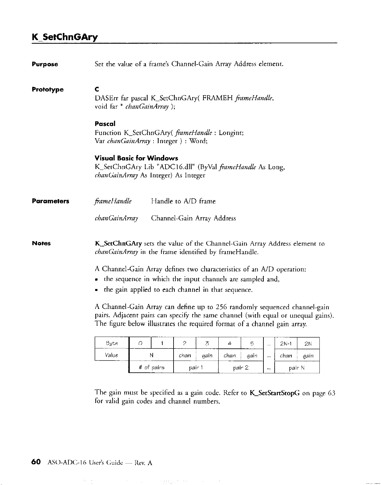
A Channel-Gain Array defines two characteristics of an A/D operation:
.
the sequence in which the input channels are sampled and,
.
the gain applied to each channel in that sequence.
A Channel-Gain Array can define up m 256 randomly sequenced channel-gain
pairs. Adjacent pairs can specify the same channel (with equal or unequal gaiw).
The figure below illustrates the required format of a channel gain array.
we
V&K N than :
0
# of pairs
1
2 3
pair 1 pair 2
gain
4 5
than ~ gain than gain
ZN-1 2N
pair N
The gain must be specified as a gain code. Refer to K-SetStat&opG on page 63
for valid gain codes and channel numbers.
60 ASO-AM:-16 Usrr’s (:;uidc - Rev. A
Page 65

Purpose
Set the value of an A/D frame’s Gain Code element.
Prototype c
DASErr far Pascal K-SetG( FRAMEH fiameHandle, short gainCode );
Pascal
Function K_SetG( j?ameHandk : Longint; @nCode : Word ) : Word;
Visual Basic for Windows
K_SetG Lib “ADClb.dll” (ByVal frameHandle As Long.
ByVal gain&de As Integer) As Integer
Parameters
Notes
JiameHandle
gain Code Gain Code. Valid valuer: 0 = lx, 1 = 10x. 2 = 100x
K-SetG sets the Gain Code element to gainCode in the frame identified by
fiameHandle.
See page 31 for the A/D voltage ranges that correspond to each gain
Page 66
K-SetStartStopChn
Purpose
Set the values of an A/D frame’s Start Channel and Stop Channel elements.
Prototype c
DASErr far Pascal KPSetStartStopChn( FRAMEH /FameHandle, short Jtart:
short xoj9 );
Pascal
Function K-SetStartStopChn( 8ameHandle : Longint; start : Word;
stop : Word ) : Word;
Visual Basic for Windows
K-SetStartStopChn Lib “ADClG.dll” (By&l fiameHandle As Long,
ByVal stalz As Integer, ByVal stop As Integer) As Integer
Parameters
jiameHandle Handle to A/D h-ame
start
stop
Start Channel. Valid values: 0, 1,...,7(m+l), where rn is the
number of connected STA-EX8.
Stop Channel. Valid values: 0, 1,...,7(m+l), whew m is the
number of connected STA-EXH.
Notes
K-SetStartStopChn assigns values to the following elements in the frame
identified by fiameHandle:
.
the Start Channel element is assigned the value in start
.
the Stop Channel element is assigned the value in stop
Use K_SetChnGAry to specify a non-sequential channel-scanning sequence.
Page 67
Purpose
Set the values of an A/D frame’s Start Channel, Stop Clunnel, and Gain Code
elements.
Prototype
Parameters
c
DASErr fat pascal K_SetStartStopG( FRAMEH frameHandle, short mzrr.
short sop, short gainCode );
Function K-SetStartStopG( fiameHandle : Longint; start : Word;
stop : Word: gainCode : Word ) : Word;
Visual Basic for Windows
K_SetStartStopG Lib “ADC16.dll” (ByVal ,fiameHand/e As Long,
ByVal start As Integer, ByVal stop As I ntegct, By&I gaincode As Integer)
As Integer
,fiameHandlc
start
stop
Handle to A/D frame
Start Channel. Valid values: 0.
number of connected STA-EXS.
Stop Channel. Valid values:
number of connected STA-EXS.
0, 1,....7(m+l), where m i\ rhr
1,....7(m+l), where m i\
rlw
Notes
gainCode
K-SetStartStopG
by jGameHandle:
.
the Start Channel element is assigned the value in start
.
the Stop Channel element is assigned the value in stop
.
the Gain Code element is assigned the value in ,gahCode
Use
K-SetChnGAty
an m-ordered ctlannel-scanning sequence.
See page 31 for the A/D voltage ranges that correspond to each gain
Gain Code. Valid values: 0 = Ix.
assigns values to the following elements io the frame idrntilird
to specie) different gains for different channels or to specify
1 = 10x. 2 = 100x
Page 68

K SyncStart
Purpose
Start a sytlctlronous-mode A/D operation.
Prototype C
DASErr far Pascal KPSyncStart( FRAMEH j’iamet-landle );
Pascal
Function K_SyncStart( JzmeHundle : Longint ) : Word;
Visual Basic for Windows
K-SyncSrart Lib “ADCl6.dll” (ByVal fiameHandle As Long) As loreget
Parameters
Notes
/izmeHandle Handle to A/D hame
K_SyncStan starts the synchronous-mode A/D operation defined in the frame
identified byjGnzehand.!t.
See page 29 for a description of the format in which the driver stores the
acquired values.
See page 15 for a discussion of the programming casks associated with
synchronoils-mode A/D operations.
Page 69

File I/O Driver
4.1
Overview
The File I/O Driver serves as an interface between your application
program and the board’s acquisition & control operation\. The driver ha\
its own set of File l/O Coumlands. Each of these English-like commandz
corresponds to a board operation. Your program can use the command\
to perform
The driver acts like a file device: consequently. your program cx LW it\
own file I/O functions (for example, INPUT and WIN7 if you arc
programming in HASI to communicate with the driver. To rxcutr a
board operation, your program outputs a File l/O Command to the drivrr.
The driver interprets the command, executes the corresponding opcrdtion.
and stores the result in its internal buffer. Your program can then input
this result from the driver.
a variety
of
acquisition & control operations.
(hprcr
4
- File I/() l)rivcr
65
Page 70
Driver components
The File I/O Driver consists of two components: the dl-iver program
(MA~)(~:I 6.EXE) and one of the Virtual Instrmm3~t programs (VLEXE 01
VITASKEXE). You can use either of the Virtual Instrument programs.
These two programs differ in the amount of memory each uses and in
their ability to provide access to the Pop Up Control Panel (tefer to the
ADC-I6 Useri Guide for a complete description of the Pop Up Contl-ol
Panel).
VLEXE
VI.EXE uses approximately 51 K of RAM. If your program requires access
to the Pop Up Contml Panel, you must load VI.EXE.
VITA!XI!XE
VI’I’ASK.EXE uses approximately 21 K of RAM. If your program does not
require access to the Pop Up Control Panel, you can load either
VITASK.EXE or VLEXE.
4.2 loading and unloading the driver -
As described in the previous section, the driver consists of the driver
program (MADC16,EXE) and one of the Virtual Instrument programs
(VI.EXE or Vl’I’ASK.EXE). The order in which you load these programs is
significant.
To load the driver, load the driver programs in the following orders
VI.EXE or VI’I’ASK.EXE
MAL)CI 6.EXE.
To unload the driver, unload the driver ptograms in the following order-:
MAD(:: I 6. EXE
VI.EXE or VITASK.EXE.
To load or unload the drivel; you must execute two sepal-ate DOS
command lines (one for either VI.EXl! or VI’I’ASK.EXE, one fat
MAL)CI 6.EXE). There are two ways to execute thesr command lines:
. You can enter the command lines at the DOS prompt, or
n
You can create a batch file that contains the command lines and then
tun the batch file.
In either case, make sure that you execute the commands io the correct
order.
Page 71

Command line
syntax
The command line syntax descriptions presented in this section use the
following typographic conventions:
. [ ] - Entries enclosed between square brackets ate mandatory. Do not
include the brackets in the command line.
. { 1 - Entries enclosed between curly brackets are optional. To include
the optional entry in the command line, specify only what is between
the brackets (do not include the brackets in the command line).
. ( ) - Entries enclosed in parentheses represent the valid values for a
command argument. The valid values are separated by commas. SprciFy
only one of the valid values from the group (do not include the
parentheses in the command line).
. The case of the letters in an entry is not significant; entries can be
specified in uppercase, lowercase. or mixed case.
l
Entries shown in bold&x type must be specified exactly as shown
(except for case).
. Entries shown in italic describe the type of entry that should be
specified. For example. if the entry is given as /&name, then the entry
you specify must be a valid filename (%s’I:IM’I’, for example).
Page 72

VI syntax
(&vc[:] ] {path}VI i [mono] ) { [IHK=kq] 1 { [IMK=kq] 1 1 [/SK=kcy] 1 1 [IU] i
[mono]
Specifies that VI will run in Monochromatic mode. If mono is not
specified, VI will assume that it is running on a color nmnitor.
[/HK=kq]
(Help Key) Specifies the key that involces the Pop Up Control Panel
Help screen. key must be one of the following:
A, B, .,,, 2
0, 1, . . . . 9
Fl, F2, . . . . FIO
Tab, Esc, or !
or any of the above preceded by Ctrl or Ctrl Alt.
examples:
/HK=F2 specifies [@zzI as the Help Key
/HK=Alt Tab specifies 1~~~1 ~ [~atl as the Help Key
[/MK=key]
(Mode Select Key) Specifies the ltey that switches the Pop Up Control
Panel to Keyboard Control Mode. See explanation of [/HK=] above fol
valid kry values.
VITASK syntax
[/SK=kq]
(Instrument Select Key) Specifies the ltey that cycles througll multiple
ADC16 boards. See explanation of [/HK=] above for valid kLy values.
idrive[:] I {pathJVlTASK ( [IU] I
[/cJl
Unloads VI from memory.
Page 73

MADC 16 syntax
{drhe[:]t (,mhIMADCl6 {/F=c@let (lPK=keyt {/Name=bonrdNmc) (IV}
(/F=c&File/
Specifies the board configuration file.
{/PK=key}
(Pop Up Control Panel Key) Specifies the key that invokes the Pop
Up
Control Panel. See the description of [/HK=] under VI syntax for the valid
kg values. The dehult Pop Up Control Paoel Key is Ah F6.
{IName=boardName)
(Board Name) Assigns a user-specified oame to the board that i\ at the
address specified in the driver configuration file. You most ox /Name=
when you have two boards installed and you waor to simultaneously
display the Pop Up Control Panel for both of them. boardName n~~tsc
comain one to eight characters; any character that i\ valid for a DOS tik
name can bz used.
wt
Unloads MADC16 from ntemory.
Example
Suppose the following conditions exist:
m your program needs access to the Pop Up Control Panel
. you want the driver configured according to the information in a
configuration file named (:US’l‘OM.(:F(;
m VI.EXE. MAD(::Ih.EXF., and CUS’I‘OM.(:E‘(; are io the (::\Al)(:lh
directory
The following command lines load the File I/O Driver appropriately for
the conditions listed above:
C:\ADClG\VI
C:\ADClG\MADC16 /F=C:\ADC16\CUSTOM,CFCi
(kapru 4 File I/O Ihivcr 69
Page 74

4.3 language-specific programming notes -
This section provides specific programming guidelines for each of the
supported languages. Additional programming information is available in
the AS0 example programs. Refer to the FILES.DOC tile for names and
descriptions of the AS0 example programs.
Borland Turbo C
Supported versions
Opening the driver
Sending commands/
Retrieving results
2.0 and higher
The code listed below shows the correct procedure to open the driver and
clear its internal buffer. This code references the PrintError error handlet
defined under- Trapping Errors.
1" Open Driver for reading and writirlg ~*I
ADC16 = fopen( "$ADC16"."r+"):
I* Check for Error *I
if (ADC16 == NULL) PrintErrorO;
I* Clear the driver's internal buffer ~^I
fprintfc ADC16, "Clear" 1;
fflush (ADC16):
if (errno !=O) return(l):
The following notes provide general guidelines for sending commands and
retrieving results with Borland Ttrrbo C:
n
Use fprintf( ) to send commands to the driver.
- Use fgets( ) to retrieve results from the driver.
n
Call rewind( ) between successive calls to fprinrf( ) and fputs( ).
l
Call fclose( ) and freopen( ) betweet successive calls to fgets( ) and
fprintf( ).
m Call flush( ) after an fprintf( ) to insure tlmt the command sent by
fprintf( ) is flushed from the DOS buffer.
70 A% I-AIIX- 16 User’s (~;uide - kv. A
Page 75
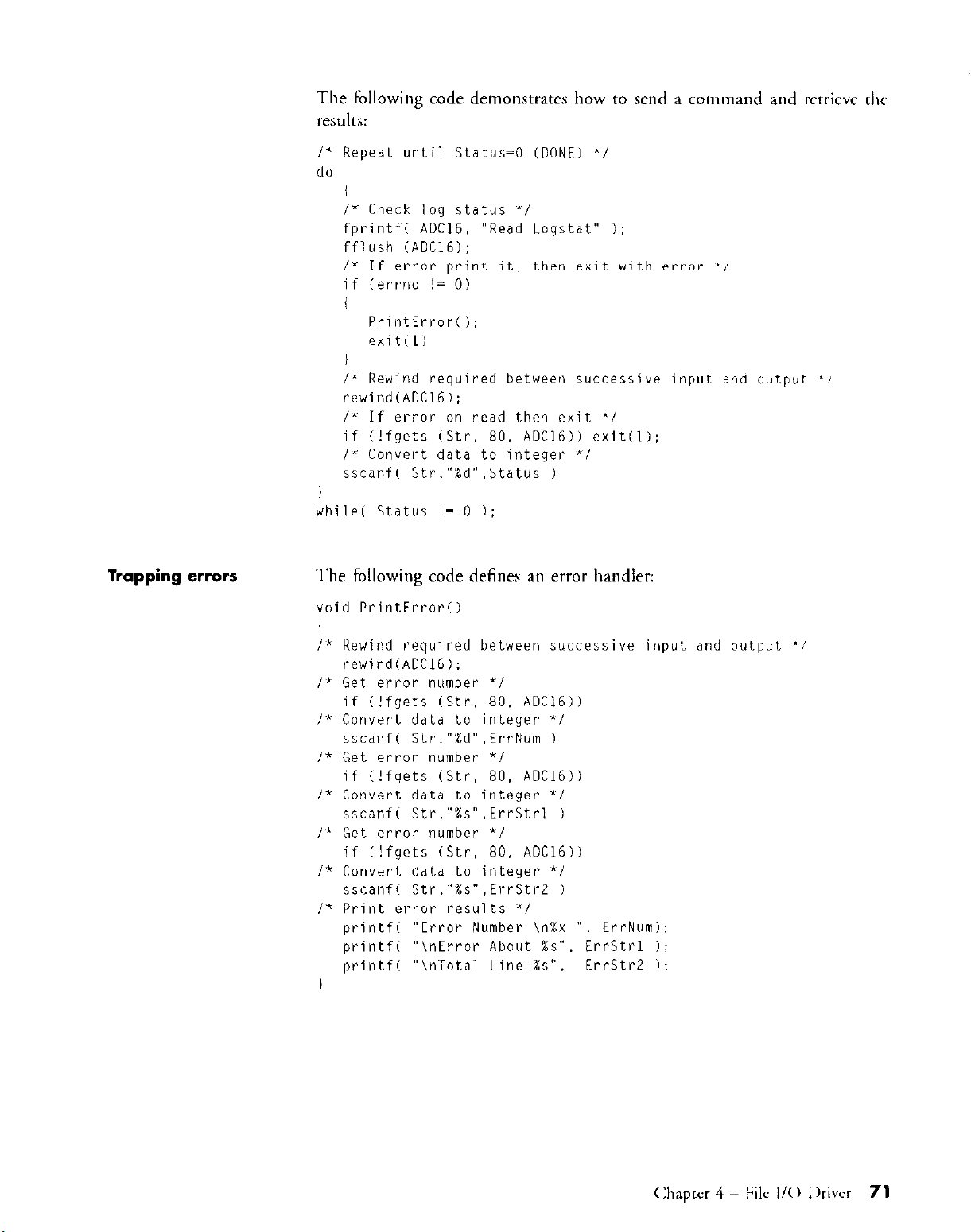
I' Repeat until Status=0 (DONE) "1
do
I
/* Check log status *I
fprintfc ADC16. "Read Logstat" i:
fflush (ADClG);
/* If error print it, then exit with error ^I
if (err-no != 0)
1
PrintErrorO;
exit(l)
I
I* Rewind required between successive input and output '!
rewind(AOC16):
I* If error on read then exit "i
if (!fgets (Str. 80. ADC16)) exit(l);
I* Convert data to integer "1
sscanf( Str."Xd".Status 1
I
while( Status != 0 ):
Trapping errors
The following code defines an error handler:
void PrintError
I
Ii Rewind required between successive input and output 'I/
rewind(ADC16);
/' Get error number */
if (!fgets (Str. 80. ADCI6))
I" Convert data to integer "I
sscanf( Str,"%d".ErrNum 1
I* Get error number *I
if (!fgets (Str. 80. ADC16)I
I* Convert data to integer *I
sscanf( Str."%s".ErrStrl 1
I* Get error number *I
if (!fgets (Str. 80. ADC16))
P Convert data to integer "I
sscanf( Str."%s".ErrStrE 1
I* Print error results *I
printf(
printf(
printf(
I
"Error Number \n%x ", ErrNum):
"\nError About %s". ErrStrl 1:
"\nTotal Line Xs". ErrStr2 1:
(:haprcr 4 - File I/O I)rivcr
71
Page 76
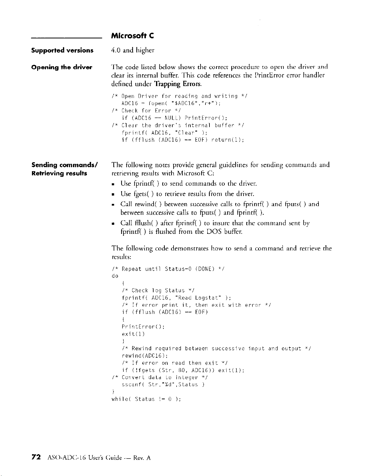
Microsoft C
Supported versions
Opening the driver
Sending commands/
Retrieving resulfs
4.0
and higher
The code listed below shows the correct procedure to open the driver and
clear its internal buffer. This code references the PrintError errof- handlel
defined under Trapping Errors.
I* Open Driver for reading and writing *I
ADC16 = fopen( "$ADC16"."r+"):
I" Check for Error *I
if (ADC16 == NULL) PrintErrorO;
I* Clear the driver's internal buffer "I
fprintfc ADC16. "Clear" 1;
if (fflush (ADC16) == EOF) return(l):
The following notes provide general guidelines for sending commands and
retrieving results with Microsoft C:
. Use fprintf( ) to send commands to the driver.
n
Use fgets( ) to retrieve results from the driver.
. Call rewind( ) between successive calls to fprintf( ) and @uts( ) and
between successive calls to fputs( ) and fprintf( ).
l
Call Hush( ) after fprintf( ) to insure that the command sent by
fprintf( ) is flushed from the DOS buffer.
The following code demonstrates how to send a command and retrieve the
results:
/" Repeat until Status=0 (DONE) */
do
I* Check log Status *I
fprintfc ADC16, "Read Logstat" 1:
1' If error print it, then exit with error *I
if (fflush (ADC16) == EOF)
PrintErrorO:
exit(l)
I
I* Rewind required between successive input and output *I
rewind(ADC16):
/* If error on read thw exit 'I
if (!fgets (Str. 80. ADC16)) exit(l):
I* Convert data to integer '1
sscanf( Str."%d",Status 1
I
whiled Status != 0 1;
Page 77

Trapping errors
The following code defines an error handler:
void PrintError
I
I* Rewind required between successive input and output 'I
rewind(ADC16):
I* Get error number *I
if (!fgets (Str. 80. ADClb))
I* Convert data to integer *I
sscanf( Str,"%d".ErrNum 1
I* Get error number *I
if (!fgets (Str. 80. ADC16))
I* Convert data to integer *I
sscanf( Str."%s".ErrStrl 1
I* Get error number *I
if (!fgets (Str, 80. ADCI6))
I* Convert data to integer 'I
sscanf( Str,"%s".ErrStrZ 1
/* Print error results */
printf( "Error Number \n%x I", ErrNum):
printf( "\nError About %s". ErrStrl 1:
printf(
"\nTotal Line %s", ErrStr2 1:
Supported versions
Opening the driver
Borland Turbo Pascal
4.0
and higher
The code listed below shows the correct procedure to open the driver and
clear its internal buffer. This code references the GetError error handler
defined under Tclpping Errors.
(* Main 'k)
BEGIN
Assign(ADClGIN. 'bADC16'):
Assign(ADC16OUT. '$ADC16');
(" Input, PASCAL has no read/write text files *)
Reset(ADC16IN):
(* Output, PASCAL has no read/write text files *)
Rewrite(ADC16OUT):
(Ihaprer 4 - t;ilc I/O Ihivcr 73
Page 78

Sending commands/
Retrieving results
The following notes provide general guidelines for sending commands and
rettieving results with Borland Xwbo Pascal:
. USC Writeln( ) to send commands to the driver.
. Use Readln( ) to retrieve results from the drivel:
. All strings used for retrieving data from the driver mut be declared as
STRING[255].
The following code demonstrates how to send a command and retrieve the
results:
status := 1:
V' Wait for status to be DONE "1
WHILE Status 0 0 DO
BEGIN
writeln(ADC16OUT;Read Logstat'):
IF (IOResult 0 0) THEN GetError :
(* Status was declared as integer *~I
ReadLn(AOC16IN,Status);
END
Trapping errars
The following code defines an et,-ot handler:
PROCEDURE GetError ;
BEGIN
readln(ADC16IN.ErrNum):
readln(ADC16IN.AStr):
readln(ADC16IN.BStr);
writeln('Driver Error Has Occurred !!'I:
writeln('MADC16 Error Number => '.ErrNum):
writeln('Error => ',BStr):
writeln('On Command Line of => ',Astr):
Halt(l)
END:
Page 79

Microsoft Pascal
Supported versions
Opening the driver
3.0 and higbet
Microsoft Pascal programs communicate with the driver via a file handle of
the Pascal type TEXT. This type of file handle allows files to
simtlltaneously be open for input and output. Consequently. only one tilt
handle is required and should be ASSIGNed for both input and output.
The codr listed below shows the correct procedure to open the driver and
clear its internal buffer. This code references the GetError error handler
defined under Trapping Errors.
C* Main ~*I
BEGIN
(" Open device driver for I/O random access '1
Assign(ADC16 .'$AOC16');
(" Direct Mode insures flush after WriteLn "i
ADC16.MODE := DIRECT:
(" Rewrite opens and rewinds the file ~I)
Rewrite(ADC16):
(hptcr 4
- Filu I/0 Ikivcr
75
Page 80
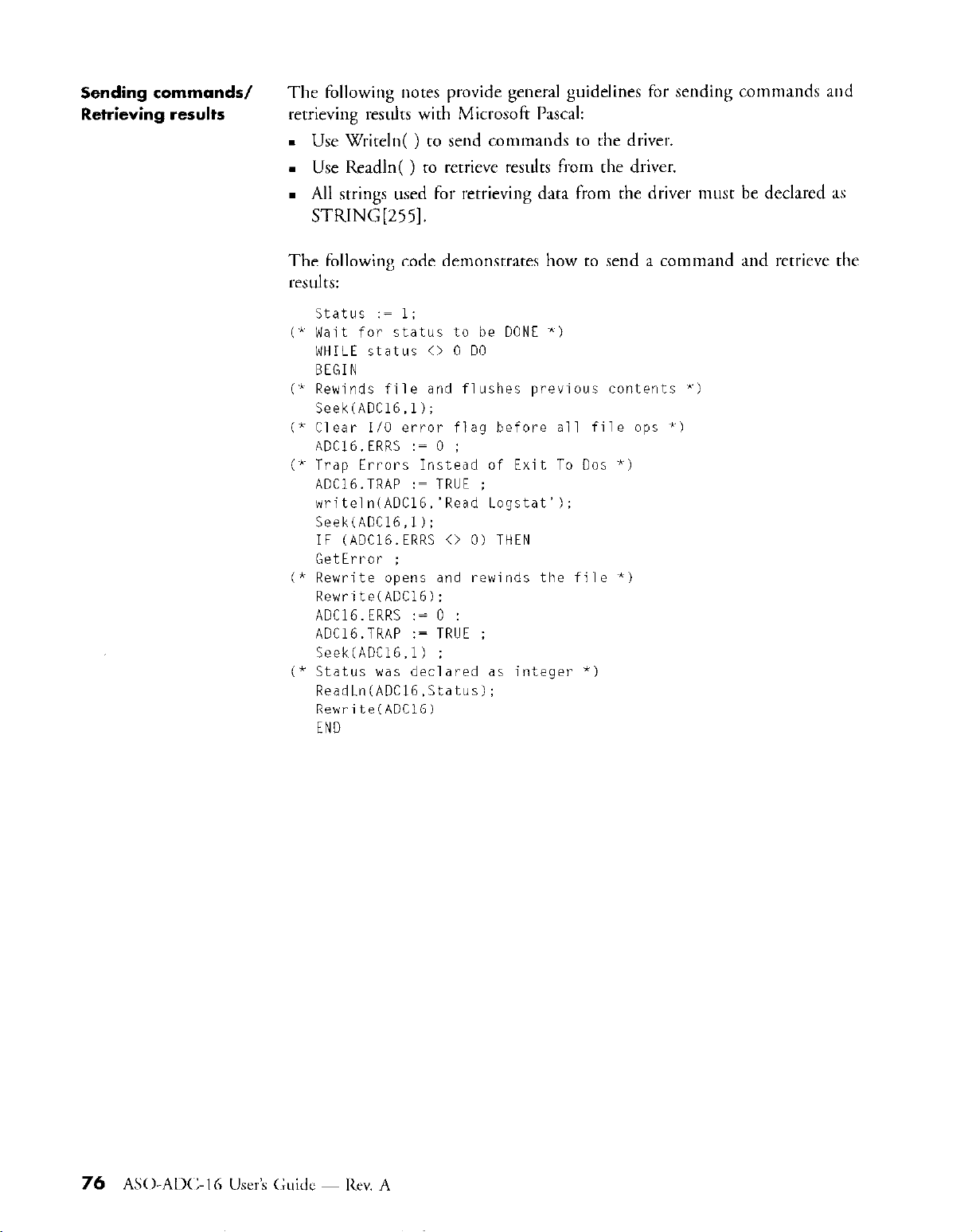
Sending commands/
Retrieving results
The following notes provide general guidelines for sending commands and
retrieving results with Microsoft Pascal:
. Use Writeln( ) to send commands to the driver.
m Use Readln( ) to retrieve results from the driver.
.
All strings used for retrieving data from the driver must be declared as
STRING[255].
The following code demonstmes how to send a command and retrieve the
results:
status := 1;
(" Wait for status to be DONE *)
WHILE status 0 0 DO
BEGIN
(" Rewinds file and flushes previous contents "1
Seek(ADC16.1);
(* Clear I/O error flag before all file ops ')
ADC16,ERRS := 0 :
(" Trap Errors Instead of Exit To DOS *)
AOC16.TRAP := TRUE ;
writeln(ADClb.'Read Logstat');
Seek(ADC16,l):
IF (ADC16.ERRS 0 0) THEN
GetError ;
(" Rewrite opens and rewinds the file "1
Rewrite(ADC16):
ADClG.ERRS := 0 :
ADClG.TRAP := TRUE ;
Seek(ADC16.1) ;
(* Status was declared as integer *)
ReadLn(ADClG.Status):
Rewrite(ADC16)
END
Page 81
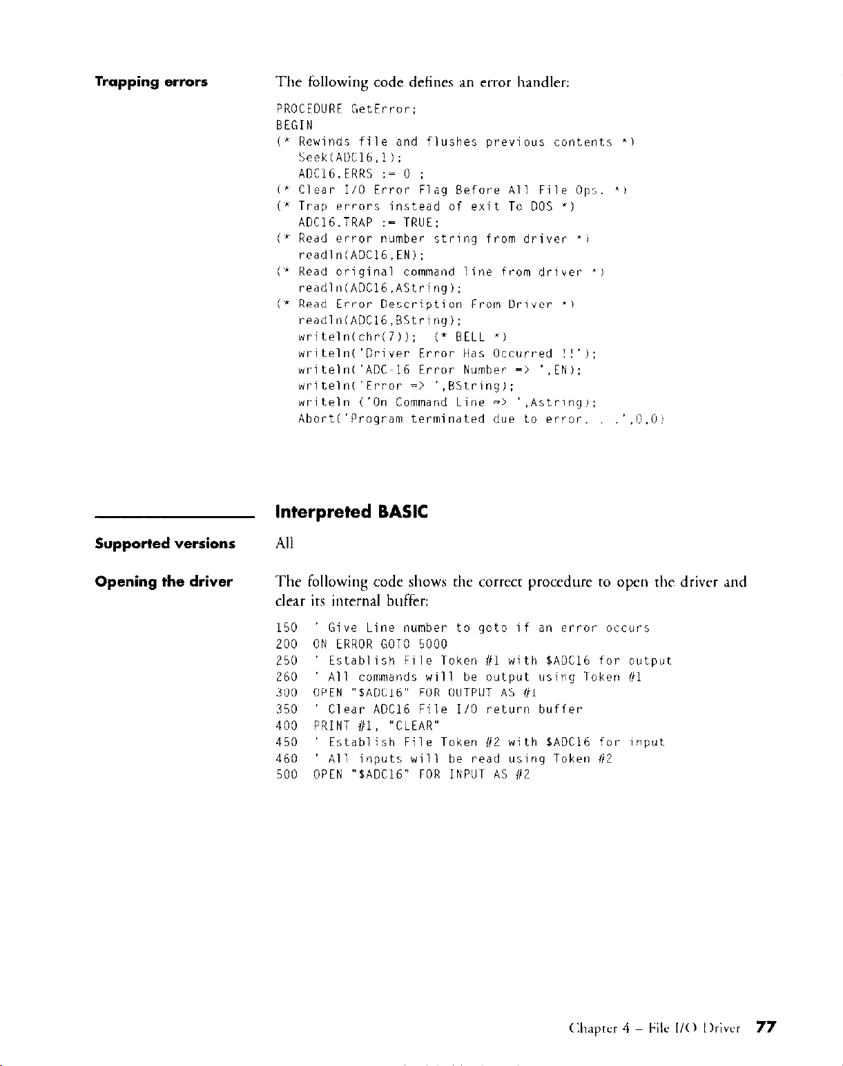
Trapping errors
The following code defines an error handler:
PROCEDURE GetError;
BEGIN
(* Rewinds file and flushes previous contents "1
Seek(ADCl6.1);
ADC16.ERRS := 0 :
(*~ Clear I/O Error Flag Before All File 0~:. "1
(" Trap errors instead of exit To DOS '1
ADC16.TRAP := TRUE:
P Read error number string from driver 'i
readln(ADCl6,EN):
Vk Read original command line from driver 'J
readln(ADC16.AString):
i* Read Error Description From Driver I)
readln(ADCl6,BString):
writeln(chr(7));
writeln('Driver Error Has Occurred ! !'):
writeln('ADC-I6 Error Number => '.EN):
writeln('Error => ',BStrinq);
writeln ('On Command Line => '.Astring,:
Abort('Program terminated due to error. .'.@.W
(' BELL "1
Supported versions
Opening the driver
Interpreted BASIC
All
The following code slmws the cottect procedure to open the driver and
clear its internal buffer:
150
' Give Line number to goto if an error occurs
200
ON ERROR GOT0 5000
250
260
300
350
400
450
460
500
Establish File Token i/l with $AOCI6 for output
All commands will be output using Token l/l
OPEN "BADC16" FOR OUTPUT AS #l
Clear ADC16 File I/O return buffer
PRINT i/l, "CLEAR"
Establish File Token 112 with SADCl6 for input
All inputs will be read using Token ii2
OPEN "$ADC16" FOR INPUT AS 112
(hptur 4 File l/O I)rivcr
77
Page 82

Sending commands/
Retrieving results
The following notes provide general guidelines for sending commands and
retrieving results with Interpreted BASIC:
m Use PRINT to send commands to the driver.
. Use INPUT to retrieve results from the driver.
The following code demonstrates how to send a command and retrieve the
Trapping errors
1000 PRINT #l/READ LOGSTAT'
1010 INPUT #2, ST%
1020 IF VAL(STB)OO goto 1010
Send command which will
fill Device's Return Buffer
with Status.
Read status into string.
If the Value of Status is
' not zero. then AD is busy.
Wait for status to be done.
The following code defines an error handlers
START OF ERROR HANDLER
5000 Beep
5010 IF ERR=75 GOT0 5060
5020 IF ERR=68 GOT0 5060
5030 IF ERR=57 GOT0 5060
5040 IF ERR = 62 GOT0 5130
5050 Print ERR : RESUME
5060 INPUT #Z,EN
5070 LINE INPUT #Z.A$
5080 LINE INPUT 1/Z. B
5090 PRINT "Error number ":EN
5100 PRINT "ERROR "86
5110 PRINT "On command line of ":A$
5120 STOP Stop execution
5130 PRINT "Data Not Available"
5140 STOP
Signal error.
GWBASIC may return
75, 68. or 57 for
a SYNTAX error.
Error 62 is an attempt
' to read from a device ttlat
has no data to read.
' If none of the above, then
error is not from driver.
Read driver error ii.
Read part of line that
contained error.
Read entire line ils
received.
Print info received from
from syntax error.
Print error 62 message
78
ASO-AlK:-lh User's (;uiJc - I<cw A
Page 83

QuickBASIC
Supported versions All
Opening the driver
Sending commands/
Retrieving results
The following code shows the correct procedure to open the driver and
clear its inre&l buffer:
ON ERROR GOT0 ErrHandler
OPEN "$ADC16" FOR OUTPUT AS i/l
PRINT #I, "CLEAR"
OPEN "'6ADC16" FOR INPUT AS 1/Z
Give line number to gotc
if an error occurs.
Establish file token ill
with IADC16 for output.
All commands will be output
using token (il.
Clear ADC16 file I/O
return buffer.
Establish file taker #2
with $ADCI6 for input.
All inputs will be read
using token 112.
The following notes provide general guidelines for sending commands and
retrieving results with Quick BASIC:
l
Use PRINT to send commands to the driver.
l
Use INPUT to retrieve resulrs from rhe driver.
The following code demonstrates how to send a command and retrieve the
results:
WaitForDone:
PRINT #l,"READ AD STATUS"
INPUT 112. STB
IF VAL(ST$)<>O goto WaitForDone
Send command which will
' fill device return buffer
with Status.
Read Status into string.
' If the value of status
is not zero ther AD
is busy; wait for Status
to be done.
(:llaprer 4 - MC II0 IIrivcr
79
Page 84
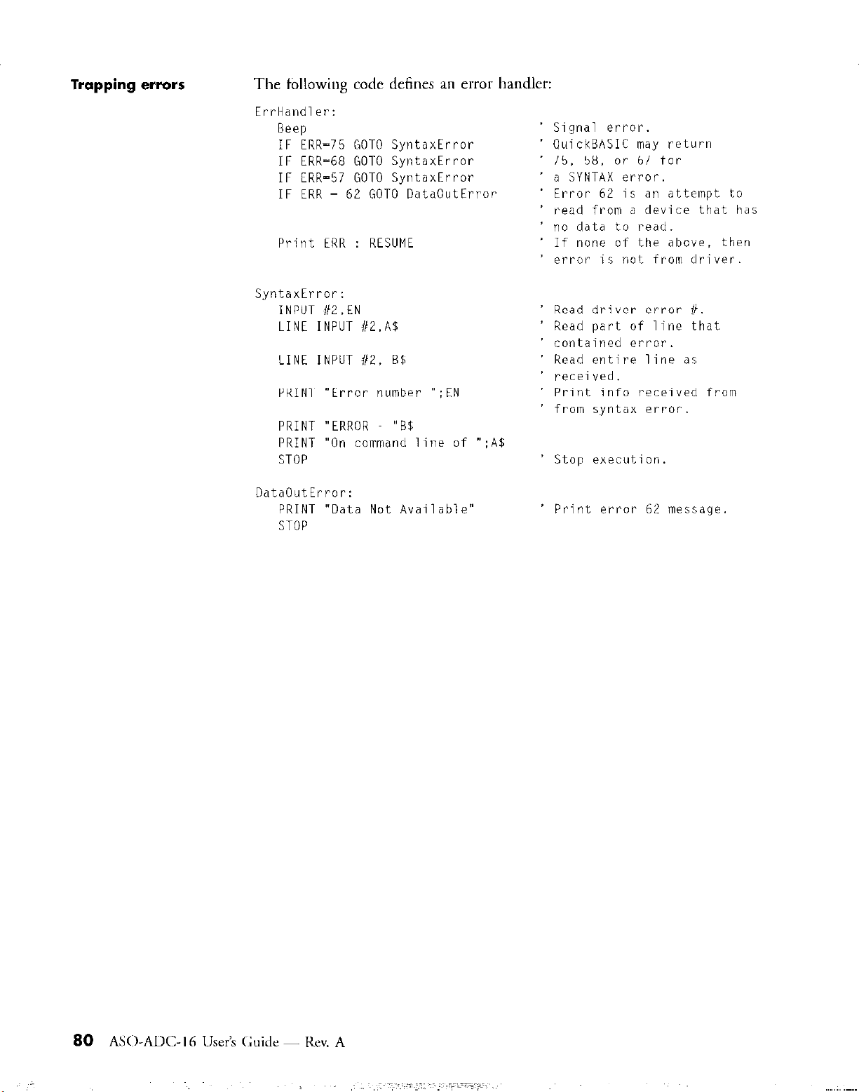
Trapping errors
The following code defines an error handler:
Err-Handler:
Beep
IF ERR=75 GOT0 SyntaxError
IF ERR=68 GOT0 SyntaxError
IF ERR=57 GOT0 SyntaxError
IF ERR = 62 GOT0 DataOutError
Print ERR : RESUME
SyntaxError:
INPUT IIZ.EN
LINE INPUT iiZ.A$
LINE INPUT i/Z, B$
PRINT "Error number ";EN
PRINT "ERROR "BB
PRINT "On command line of
STOP
":A%
' Signal error.
' QuickBASIC may return
' 75. 58, or 67 for
' a SYNTAX error.
' read from a device that has
Error 62 is an attempt to
no data to read.
If none of the above, then
error is not from driver.
Read driver error ii.
Read part of line that
contained error.
Read entire line as
received.
Print info received from
from syntax error.
Stop execution.
DataOutError:
PRINT "Data Not Available"
STOP
' Print error 62 message
AS0ADC-I 6 User’s (~;uillc - Kev. A
80
Page 85

File I/O Commands
5.1 Functional grouping -
The File I/O Commands can be logically grouped according to the
functionality that each provides. This section lists each command ah a
member of one of the following groups:
. Setup and Initialization
. A/D operations
n
Pop Up Control Panel
5
Setup and
Initialization
AID operations
ClC%U
Clears all data that the driver has prepared for your programs next input
operation.
ADStart
Enables A/D acquisition.
ADStop
Disables A/D acquisition,
Read ADType
Returns the A/D transfer mode in which the next A/D operation will
execute.
Page 86

AID operations
(cont’d)
Read Channel
Returns the A/D value acquired on a specified channel
Read Gain
Returns a code that indicates the current global gain
Read Level
Returns the current interrupt level.
Read {Mode/LogFde/Date/BloddlogS~tl
Returns the conditions that define the next StartLog.
Read Range
Returns the current h&scale A/D range.
Read Startchannel
Returns the channel number of the first channel in the current
channel scan.
Read Stopchannel
Returns the channel number of the last channel in the current
channel scan.
Set ADTj.pe
Specifies the A/D transfer mode in which the next A/D operation will
execute.
Set Gain
Sets the global gain.
Set
Level
Sets the interrupt level to be used for the next A/D operation
Set {Mode/LogFile/Dare/BloddLogS~t}
Sets conditions that define the next
StartLog.
82
AS0ADC-I 6 User’s Guide - Kev. A
Page 87

A/D operations
(cont’d)
set Startchannel
Specifies the first channel that will be scanned during the nmt
A/D operation.
set Stopchannel
Specifies the last channel that will be scanned during the next A/D
operation.
StartLog
Writes the current A/D data into a file.
StopLag
Stops current logging operation.
Pop up Control Panel
Hide
Hides
Lock
Disables keyboard and IIIOUSC control of the Pop Up Control Partrl
the Pop Up Control Panel.
Read Units
Returns the units that the Pop Up Control Panel will MC to display data.
Set U&5
Sets the units that the Pop Up Control Panel will wse to display data,
Show
Causes the display of a specified panel of the Pop Up Control Panel.
UniOCk
Enables keyboard and mouse control of the Pop Ut> Control Panel
Page 88

5.2 Command reference
The following notes describe the conventions and stand& terminology
used in the remainder of this chapter:
About Syntax entries
. The Syntax heading for each command lists two lines. The first line is
rhe standard form of the command. The second line is rhe abbreviated
form of the command. The abbreviated form shows the minimum
characters in each keyword that must be present in order for the dl-ivcl
to recognize the command. The driver recognizes both forms; the
abbreviated form is provided as a convenience.
. Se is shown as the minimum abbreviation for Set keyword. However,
Set (or its abbreviation Se) can be omitted from any command whose
standard form includes the Set keyword. For example, Set ADType can
be specified as ADType.
. { ] - Curly brackets enclose a set of command keywords from which
one must be selected to define the command; keywords are separated by
a backslash. For example,
represents five commands:
Read Block,
. ( ) - Entries enclosed in parentheses are c~l~stunt arguments (see note
about variable arguments below). The constant arguments are sepal-ared
by commas. The constut arguments must bc specified exactly as they
are shown. For example,
Set Units command
be either
and
Read LogStat.
ADcodes
or
Read {Mode/LogFile/DateIBIock/LogStat}
Read Mode, Read LogFile. Read Date,
Set Units (ADcodes,Volts)
rakes
a single argument, and that argument must
indicates that the
Volts.
. Variable arguments are shown in italic and describe the type of Y;LIW
that should be specified. For example, ,f&;lume indicates that the
argument should represent a valid filename.
Page 89
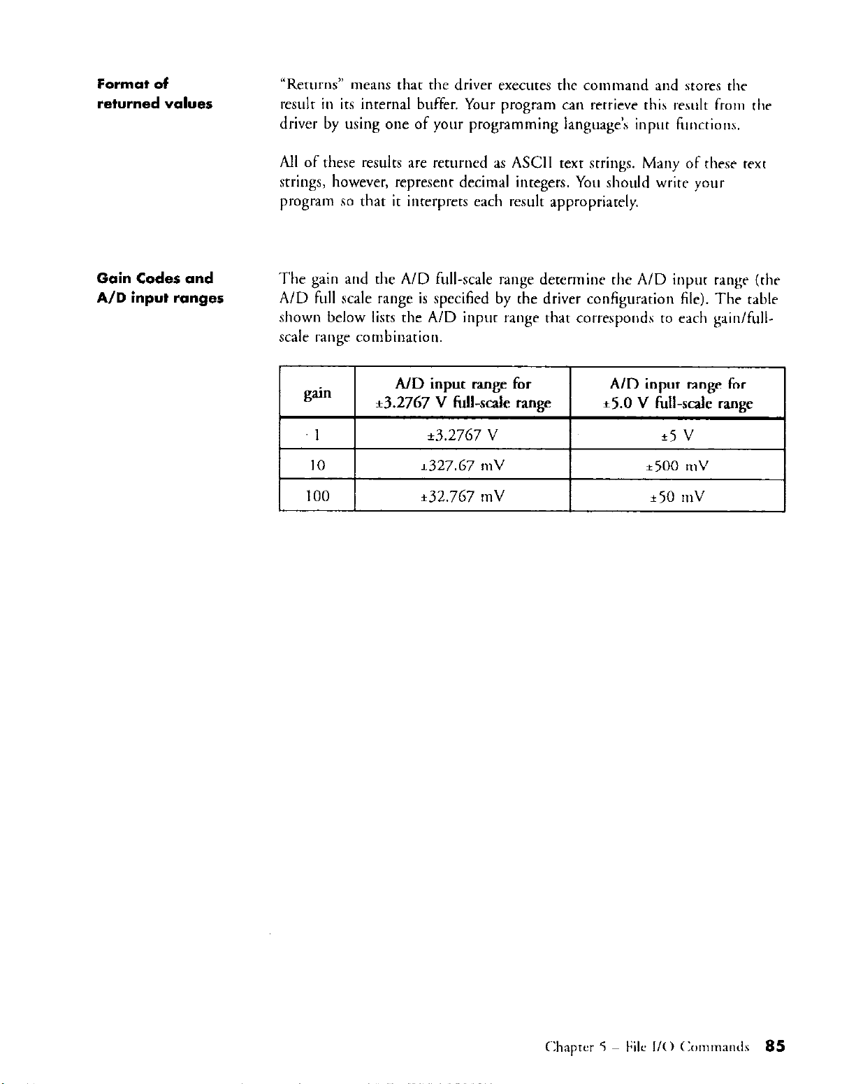
Format of
returned values
“Returns” means that the driver executes the command and stores the
result in its internal buffer. Your program can reuieve this result from thr
d'
All of these results are returned as ASCII text strings. Many of these text
wings, however, represenr decimal integers. You should wriw your
program so that it inrerprets each resulr appropriately.
b rwer y using one of your programming language’s input FIIIicGons.
Gain Codes and
A/D input ranges
The gain and the A/D full-scale range determine the A/D input rangr (thr
A/D fill1 scale range is specified by the driver configurxion file). The tablr
shown below lists the A/D input range rhar corresponds to each gain/fullscale range combinarion.
gain
1
10
100
A/D input range for A/D input range for
zt3.2767 V fihcak range *5.0 v Full-scale rangcz
e3.2767
k327.67
k32.767
V
mV
mV
*5 v
*500
* 50
n1V
mv
Page 90

ADStart
SyntalC
Description
ADStart
ADStort
Enables A/D acquisition.
ADStop
Syntax ADStop
ADStop
Description
Disables A/D acquisition.
Clear
syntax Clear
Cl
Description
Notes
Clears all data that the driver has prepared for your program’s next input
operation.
Since some versions of DOS do not call the driver when your p~mgram
issues an Open, the driver might contain input-ready data that was
prepared by a previous program. Consequently, you should issue a Clear
immediately following any Open.
86
AS0AD<:-I 6 User’s Guide - Rev. A
Page 91

Syntax Hide
Hi
Description
Notes
lock
Syntax
Description
Notes
Hides the Pop Up Control Panel
Hide is ignored if VITASK (instead of VI) was loaded intmcdiarrly beforr
MADC16 was loaded: refer to page 66 for a description of rlw diffPrences
between VI and VITASK.
Show cancels the effect of Hide.
Lock
Lo
Disables keyboard and mouse control of the Pop Up Control Panel
Use Unlock to cancel the effect of Lock.
Read ADType
Syntax Read ADType
Re ADT
Description
Return codes
Notes
Returns a code that indicates the current A/D transfer mode.
0
= Synchronous-mode
1 = Interrupt-mode
The current A/D transfer mode is the mode specified by the most recently
issued
Ser
ADType.
Page 92

Read Channel
Syntax
Description
Notes
Read Channel
Re Ch channel
Returns the A/D value acquired on the channel specified by channel. The
valid values for channel are 0, I,..., 7.
The currem units and the current gain (as specified by the most recently
issued
the returned value as follows:
.
.
Set Units
If the current units = Volts and the current gain = 1, then the value is
returned in units of Volts.
If the current units = Volts and the current gain = 10 or 100, then the
value is returned in units of MilliVolts.
Read Gain
Syntax Read Gain
Re Go
channel
and Set Gain, respectively) determine the implied units of
Description
Return codes
Returns the current global gain
1, 10, 100. Refer to the table on page 85 for the A/D input ranges that
correspond to each of these gains.
Read level
Syntax Read Level
Re Lev
Description
Notes
Returns the current interrupt level.
The current interrupt level is defined by the value of the level argument
specified in the most recently issued Set Level.
88
ASO-AM::-1 6 User’s Guide - Rev. A
Page 93

Read {Mode/LogFile/Date/Block/LogStat}
Syntax
Description
Read Mode
Re MO
Read LogFile
Re Logfile
Read Date
Re Da
Read Block
Re Eil
Read LogStot
Re Logstat
Read Mode
Returns the value of the mode argument specified in the mosr r~crnrly
issued Set
Ovel-write) in which the data will be written to the dara file by the next
Mode.
The value of mode represents the mode (New, Append or
StartLog.
Read LogFile
Returns the/&name argument specified in the most recently issued
Set LogFile. filename represents rhe name of the data file that will be uxd
by the next StartLog.
Page 94

Read {Mode/LogFile/Date/Block/LogStat}
Read Date
Returns the date argument specified in the most recently issued Set Date
dnte indicates if date stamping is enabled.
Read Block
Retums the block argument specified io the most recently issued Set Block.
block represents the otmber of data blocks that will be logged by the next
start Log.
Read LogStat
Returns the current log status,
(cont’d)
Return codes
Read Mode
0 = New
1 = Overwrite
2 = Append
Read Date
0 = Date stamping Off
1
= Date starnpiog On
Read LogStat
0
= Logging Off
1 = Logging On
Read Range
Syntax Read Range
Re Ron
Description
Returns a code that indicates the cumot A/D full-scale range
Return codes
0 = k3.2768 V
1 = +5.0 v
Page 95

Read Startchannel
Syntax Read Startchannel
Re Sta
Description
Notes
Retums the channel umber of the first channel in the current chaonel
scan.
The first channel in the current scan is defined by the most recently issued
set Startchannel.
Read Stopchannel
Syntax Read Stopchannel
Re Sto
Description
Notes
Returns the channel number of the last channel in the current chanoel
scao.
The last channel in the current scao is defined by the most recently isswd
Set Stopchannel.
Read Units
Syntax
Description
Return codes
Read Units
Re Un
(Applies only if the Pop Up Control Panel is visible). Returns a codr that
indicates the current display units on the Pop Up Control Panel.
0
= A/D codes
1 = Volts
Page 96

Set ADType
Syntax
Description
Notes
Set ADType (Interrupt,Synchronous)
Se ADT (Int,Syn)
Specifies the A/D transfer mode in which the next A/D operation will
execute.
Interrupt mode allows for the acquisition and transfer of dara using the
interrupt level set by the most recently issued Set Level. The driver detects
the interrupt that the ADC-16 issues at the conclusion of a conversion and
then reads the acquired data into memory. Because of the driver and CPU
involvement required to read the data into memory, the maximum
conversion rate in interrupt mode is limited to approximately 5 Khz.
Operations that execute in interrupt mode must use a single gain for each
channel in the scan. Interrupt-mode operations execute entirely io the
background.
Synchronous mode operates in the foreground. When an AD command
begins executing, no other board functions are available until the A/D
operation terminates. The maximum conversion throughput available in
synchronous mode is machine dependent.
Page 97

Set Gain
Syntax
Description
Arguments
Set level
Syntax
Description
Set Gain goin
Se Go gain
Specifies guin as the current global gain.
channel
0, 1,...,7
gain
1, 10, 100
Set Level (2,3,4,5,7,10,1 I ,15)
SeLev(2,3,4,5,7,10,11,15)
Sets the interrupt level to be used for the next
A/D
operation
Chapter 5 - Filr I/O (:Olrlmands 93
Page 98

Set {Mode/LogFile/Date/Block/LogRate}
SyIltCUC
Description
Set Mode (Append,New,Overwrite)
Se MO (Ap,Ne,Ov)
Set LogFile
Se Logfile fileName
h&Name
Set Date (On,Off)
Se
Da (On,Off)
Set Block
Se El numBlocks
numBlocks
Set LogRate rafe
Se tograte
rate
Set Mode (Append,New,Overwrite)
Specifies the mode in which the data will be written to the file by the next
StartLog.
Set LogFile
Specifies j&Name as the name of file that will be used by the next
SWtL0g.
fileName
Set Date (On,Off)
Specifies if date stamping is enabled.
Set Block
Specifies numBlocks as the number of blocks that will be saved by the next
StanLog. The valid values for numBlocks at-e 0, 1,...,99999.
numBlocks
Set LogRate rob
Specifies rate as the number of seconds between successive A/D
acquisitions. The valid values for rate are as follows:
. 2.0, 2.1,..., 99.9, or
. 102, 108,...,102 + 6m,...,5994 with m an integer in the range [0,382]
Page 99

Syntax
Set StartChannel
Se Sta channel
channel
Description
Specifies channel as the first channel to be scanned during tlw next A/D
operation.
Set StopChannel
Syntax Set StopChannel
Se Sto channel
Description
Specifies channel as the last channel to be scanned during the next A/D
operation.
channel
Set Units
Syntax Set Units (ADcodes,Volts)
Se Un (ADcqVo)
Description
Show
Syntax
Description
Arguments
Notes
Sets the units that the Pop Up Control Panel will use to display data.
show (1,2)
Sh Il.21
Causes thr display of the specified panel of tlw Pop Up Control Panel
1 = Main panel
2 = LogFile panel
This command is ignored if VITASK (instead of VI) was loaded
immediately before MADCl6 was loaded.
Page 100
Startlog
Syntax Startlog
Startlog
Description
WI-ices he currenf A/D data into a file accol-ding to
he condirions specified by the most recenrly issued
Set (Mode/LogFile/Date/BIoddlogS~~l.
Stoplog
Syntax
Description
stoplog
Sloplog
Stops current logging operation.
Unlock
Syntax Unlock
Un
Description
Notes
Enables keyboard and mouse control of he Pop Up Conrl-ol Panel.
Use Lock
to
CdllCCl the
effecr of U&I&.
96
ASO-AM-I 6 User’s Guide - Rrv. A
 Loading...