

Page 1

Instructions
AMT75
75 to 50 Ohm Impedance Adapter
070-9479-00
There are no current European directives that
apply to this product. This product provides cable
and test lead connections to a test object of
electronic measuring and test equipment.
Page 2

Copyright © T ektronix, Inc. All rights reserved.
T ektronix products are covered by U.S. and foreign patents, issued and pending. Information in this publication supercedes
that in all previously published material. Specifications and price change privileges reserved.
Printed in the U.S.A.
T ektronix, Inc., P.O. Box 1000, Wilsonville, OR 97070–1000
TEKTRONIX, TEK, and TEKPROBE are registered trademarks of T ektronix, Inc.
Page 3

WARRANTY
T ektronix warrants that the products that it manufactures and sells will be free from defects in materials and
workmanship for a period of one (1) year from the date of shipment. If a product proves defective during this
warranty period, T ektronix, at its option, either will repair the defective product without charge for parts and labor,
or will provide a replacement in exchange for the defective product.
In order to obtain service under this warranty, Customer must notify Tektronix of the defect before the expiration
of the warranty period and make suitable arrangements for the performance of service. Customer shall be
responsible for packaging and shipping the defective product to the service center designated by T ektronix, with
shipping charges prepaid. Tektronix shall pay for the return of the product to Customer if the shipment is to a
location within the country in which the T ektronix service center is located. Customer shall be responsible for
paying all shipping charges, duties, taxes, and any other charges for products returned to any other locations.
This warranty shall not apply to any defect, failure or damage caused by improper use or improper or inadequate
maintenance and care. T ektronix shall not be obligated to furnish service under this warranty a) to repair damage
resulting from attempts by personnel other than T ektronix representatives to install, repair or service the product;
b) to repair damage resulting from improper use or connection to incompatible equipment; c) to repair any
damage or malfunction caused by the use of non-T ektronix supplies; or d) to service a product that has been
modified or integrated with other products when the effect of such modification or integration increases the time
or difficulty of servicing the product.
THIS WARRANTY IS GIVEN BY TEKTRONIX IN LIEU OF ANY OTHER WARRANTIES, EXPRESS
OR IMPLIED. TEKTRONIX AND ITS VENDORS DISCLAIM ANY IMPLIED WARRANTIES OF
MERCHANTABILITY OR FITNESS FOR A PARTICULAR PURPOSE. TEKTRONIX’
RESPONSIBILITY TO REPAIR OR REPLACE DEFECTIVE PRODUCTS IS THE SOLE AND
EXCLUSIVE REMEDY PROVIDED TO THE CUST OMER FOR BREACH OF THIS WARRANTY.
TEKTRONIX AND ITS VENDORS WILL NOT BE LIABLE FOR ANY INDIRECT , SPECIAL,
INCIDENTAL, OR CONSEQUENTIAL DAMAGES IRRESPECTIVE OF WHETHER TEKTRONIX OR
THE VENDOR HAS ADVANCE NOTICE OF THE POSSIBILITY OF SUCH DAMAGES.
Page 4

Service Assurance
If you have not already purchased Service Assurance for this product, you may do so at any time during the product’s
warranty period. Service Assurance provides Repair Protection and Calibration Services to meet your needs.
Repair Protection extends priority repair services beyond the product’s warranty period; you may purchase up to three
years of Repair Protection.
Calibration Services provide annual calibration of your product, standards compliance and required audit documentation,
recall assurance, and reminder notification of scheduled calibration. Coverage begins upon registration; you may purchase
up to five years of Calibration Services.
Service Assurance Advantages
H Priced well below the cost of a single repair or calibration
H Avoid delays for service by eliminating the need for separate purchase authorizations from your company
H Eliminates unexpected service expenses
For Information and Ordering
For more information or to order Service Assurance, contact your T ektronix representative and provide the information
below . Service Assurance may not be available in locations outside the United States of America.
Name VISA or Master Card number and expiration
Company date or purchase order number
Address Repair Protection (1,2, or 3 years)
City , State, Postal code Calibration Services (1,2,3,4, or 5 years)
Country Instrument model and serial number
Phone Instrument purchase date
Page 5

General Safety Summary
Review the following safety precautions to avoid injury and prevent damage to
this product or any products connected to it. To avoid potential hazards, use this
product only as specified.
To Avoid Fire or
Personal Injury
Ground the Product. This product is indirectly grounded through the grounding
conductor of the mainframe power cord. To avoid electric shock, the grounding
conductor must be connected to earth ground. Before making connections to the
input or output terminals of the product, ensure that the product is properly
grounded.
Observe All Terminal Ratings. To avoid fire or shock hazard, observe all ratings
and markings on the product. Consult the product manual for further ratings
information before making connections to the product.
The common terminal is at ground potential. Do not connect the common
terminal to elevated voltages.
Do Not Operate Without Covers. Do not operate this product with covers or panels
removed.
Do Not Operate With Suspected Failures. If you suspect there is damage to this
product, have it inspected by qualified service personnel.
Do Not Operate in Wet/Damp Conditions.
Do Not Operate in an Explosive Atmosphere.
Keep Product Surfaces Clean and Dry .
Symbols and Terms
AMT75 Impedance Adapter Instructions
T erms in this Manual. These terms may appear in this manual:
WARNING. Warning statements identify conditions or practices that could result
in injury or loss of life.
CAUTION. Caution statements identify conditions or practices that could result in
damage to this product or other property.
1
Page 6

Contacting Tektronix
Product
Support
Service
Support
For other
information
To write us Tektronix, Inc.
For application-oriented questions about a Tektronix measurement product, call toll free in North America:
1-800-TEK-WIDE (1-800-835-9433 ext. 2400)
6:00 a.m. – 5:00 p.m. Pacific time
Or contact us by e-mail:
tm_app_supp@tek.com
For product support outside of North America, contact your
local Tektronix distributor or sales office.
Contact your local Tektronix distributor or sales office. Or visit
our web site for a listing of worldwide service locations.
http://www.tek.com
In North America:
1-800-TEK-WIDE (1-800-835-9433)
An operator will direct your call.
P.O. Box 1000
Wilsonville, OR 97070-1000
2
AMT75 Impedance Adapter Instructions
Page 7

AMT75 Impedance Adapter
The AMT75 (Figure 1) is a 75 to 50 W impedance adapter with low VSWR
(voltage standing-wave ratio). The adapter allows you to connect video and
communication signals from a 75 W coax cable to the 50 W input of an oscilloscope while minimizing aberrations and reflections. The AMT75 adapter fully
complies with ANSI T1.102 and ITU-T G.703
50 W TekProbe output
Figure 1: AMT75 Adapter
CAUTION. The AMT75 adapter contains components that are sensitive to
electrostatic discharge (ESD). To avoid electrostatic damage, observe ESD
precautions when handling the adapter.
75 W input
AMT75 Impedance Adapter Instructions
3
Page 8

AMT75 Impedance Adapter
Oscilloscope Connections
As shown in Figure 2a, the output of the AMT75 adapter connects directly to the
TekProbe II interface on Tektronix TDS Series oscilloscopes. With the addition
of optional accessories, the AMT75 adapter connects to any instrument with a
50 W BNC or 50 W SMA input. The shell of the input on all oscilloscopes must
connect to earth ground.
Instruments with
TekProbe II
Instruments without
TekProbe II
When you connect the adapter to instruments with the TekProbe II interface, the
instrument automatically adjusts the scale factor and sets the oscilloscope input
impedance to 50 W.
NOTE. TDS 400 and TDS 400A series oscilloscopes always interpret the
attenuation of the AFTDS adapter as B 10. The attenuation of the adapter is
actually B 5. When you use this adapter on these oscilloscopes, divide the
measurement (or scale factor) by 2 to obtain the correct value.
When you connect the adapter to instruments that do not have the TekProbe II
interface, make the settings and calculate the amplitude as follows:
H Set the oscilloscope input impedance to 50 W or use an external 50 W
termination.
H Correct your measurements for the 5X attenuation factor of the AMT75
adapter.
Displayed Amplitude × 5 = Actual Amplitude
Input Signal Connections
The female BNC input of the AMT75 adapter accepts a male BNC connector.
The signal input cable (source) must be 75 W. See Figure 2b.
CAUTION. To avoid damaging the 75 W input connector, use accessories that are
specifically designed for 75 W connections. Using 50 W connectors on the 75 W
input can damage the 75 W connector and degrade the VSWR of the AMT75
adapter.
4
AMT75 Impedance Adapter Instructions
Page 9

a) 50 W Oscilloscope connections
AMT75 Impedance Adapter
Connections to other oscilloscopes
(without the TekProbe II Interface)
50 SMA
input
BNC to SMA
50 BNC
input
1 M BNC
b) 75 W Input signal connections
Impedance Standard
75
D-1
D-2
DS-3
DS-4
STS-1
STS-3/STM-1
E-2
E-3
E-4
input
50 terminator
Data Rate (Mb/s)
270
143
44.736
139.264
51.84
155.51
8.448
34.368
139.264
Connection to Tektronix TDS Series
(with the TekProbe II Interface)
DITS
template
test signal
TekProbe input
50 BNC Male to BNC Female
50 TekProbe output
AMT75
75 BNC Input
75 BNC Male to BNC Male
Figure 2: Connecting the AMT75 adapter
AMT75 Impedance Adapter Instructions
5
Page 10

AMT75 Impedance Adapter
Specifications
This section contains the specifications and compliances for the AMT75
Impedance Adapter. All specifications are guaranteed unless noted as “typical.”
Typical specifications are provided for your convenience but are not guaranteed.
Specifications that are marked with the n symbol are checked in the Perfor-
mance Verification on page 8.
Specification/compliance Description
Communication and video standards D-1 (270 Mb/s) STS-3/STM-1 (155.51 Mb/s)
D-2 (143 Mb/s) E-2 (8.448 Mb/s)
DS-3 (44.736 Mb/s) E-3 (34.368 Mb/s)
DS-4 (139.264 Mb/s) E-4 (139.264 Mb/s)
STS-1 (51.84 Mb/s)
Compliance with industry standards ANSI T1.102 and ITU-T G.703
n Input impedance 75 ± 1.5% at DC
Input VSWR (return loss), typical ≤ 1.1:1 (≥ 26.45 dB) to 1 GHz (see Figure 3)
n Output impedance 50 ± 1.5% at DC
n Attenuation accuracy 5X (–14 dB) ± 1.5% at DC
Bandwidth, (–3dB) typical ≥ 1.0 GHz
Rise time, typical < 350 ps (calculated from the formula .35/bandwidth = rise time)
Rated input voltage (Power) ≤ 5 VDC or VAC
Temperature
Operating
Nonoperating
Humidity
Operating
Nonoperating
EC Compliance There are no current European Directives that apply to this product.
Pollution Degree 2 Do not operate in environments where conductive pollutants may be present.
Class 5 Limits
0_ C to + 50_ C
–55_ C to + 75_ C
Class 5 Limits
+30_ C to + 50_ C, 90 to 95% RH
–55_ C to + 75_ C, 90 to 95% RH
(333 mW)
RMS
6
AMT75 Impedance Adapter Instructions
Page 11
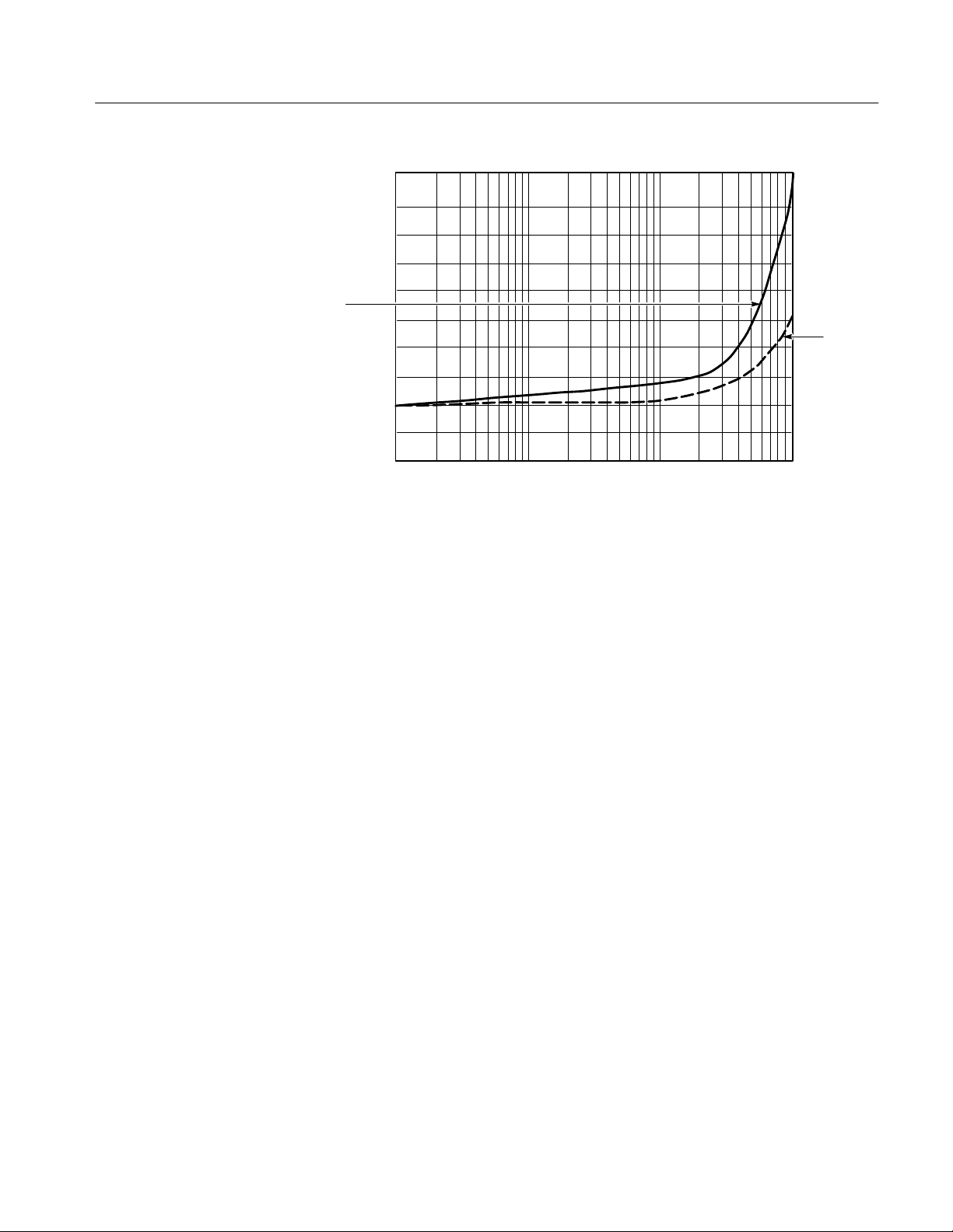
AMT75 Impedance Adapter
1.100
1.090
1.080
1.070
VSWR
1.060
1.050
1.040
1.030
1.020
1.010
1.000
1.0
10 100 1000
Figure 3: Typical VSWR and return loss
Frequency (MHz)
10
20
30
40
50
0
Return
loss (dB)
AMT75 Impedance Adapter Instructions
7
Page 12

Performance Verification
Use the following procedures to verify the warranted specifications of the
AMT75 adapter. Before beginning these procedures, photocopy the test record
on page 13 and use it to record the performance test results for your AMT75
adapter. The recommended calibration interval is one year.
These procedures are for use by qualified service personnel only.
Test Equipment
Table 1 itemizes the equipment required, provides an example or part number of
the equipment, and explains the purpose of the equipment.
T able 1: Test equipment
Description Minimum requirements Example product
Power supply (1) 1 VDC out across 75 W with
Wavetek 9100
< 0.5 mV resolution
Digital multimeter (1) 5 1/2 digit with sense, W 4 wire,
50 W and 75 W ± 0.1%,
DCV: 1 V and 200 mV ± 0.1%
75 W terminator (1) 75 W ± 0.1%, 3 V
50 W terminator (1) 50 W ± 0.1%, 2W, BNC 01 1-0123-00
BNC banana adapter (3) BNC female to dual banana plug 103-0090-00
BNC male connector (1) 1 male to 1 male 103-0029-00
50 W BNC cable (2) 2 foot BNC male 012-1342-00
50 W BNC “T” adapter (3) 2 female to 1 male BNC 103-0030-00
75 W BNC cable (3) 2 foot BNC male 012-1339-00
75 W BNC “T” adapter (2) 2 female to 1 male Pasternack Model# PE9365
50 W BNC adapter (1) 1 female to 1 female 103-0028-00
, BNC 01 1-0103-02
RMS
Kiethley 2000
Fluke 884X
8
AMT75 Impedance Adapter Instructions
Page 13

Output Impedance
Performance Verification
1. Set up the DMM as follows:
DMM Setting
Mode 4 Wire
Range 100
2. Connect the AMT75 adapter as shown in Figure 4.
NOTE. Connect the input and sense of the DMM to the output of the AMT75
adapter with a 50 W BNC T adapter, two 50 W BNC cables, and two BNC
banana adapters.
Multimeter
50.000
75 terminator
50 BNC cables,
50 T adapter,
and 50 BNC adapter
Figure 4: Test setup for output impedance
3. Check that the DMM reads 50 W $ 1.5% (49.25 to 50.75).
4. Disconnect 50 W BNC T adapter, AMT75 adapter, and 75 W terminator from
the setup.
AMT75 Impedance Adapter Instructions
9
Page 14

Performance Verification
Input Impedance
1. Connect the AMT75 adapter as shown in Figure 5.
CAUTION. To avoid damaging the 75 W input, use only 75 W connectors and
75 W cables on the 75 W input.
Multimeter
75.000 W
50 W termination
75 W BNC cables
and 75 W T adapter
50 W BNC adapter
Figure 5: Test setup for input impedance
2. Check that the DMM reads 75 W $ 1.5% (73.875 to 76.125).
3. Disconnect setup.
10
AMT75 Impedance Adapter Instructions
Page 15

Attenuation Accuracy
Performance Verification
1. Set up the equipment as follows:
DMM Setting
Mode DCV
Range 10 V
Power Supply Setting
DCV 1.000 V
2. Connect the equipment as shown in Figure 6.
CAUTION. To avoid damaging the 75 W input, use only 75 W connectors and
75 W cables on the 75 W input.
Power supply
Multimeter
+–
75 W BNC cables and 75 W T adapters
+1.0000 V
50 W termination
50 W BNC adapter
Figure 6: Measuring the power supply output voltage
3. Activate the power supply and adjust the output until the DMM reads
1.000 V.
4. Deactivate the power supply but do not change the output setting.
5. Connect the equipment as shown in Figure 7.
AMT75 Impedance Adapter Instructions
11
Page 16

Performance Verification
Power supply
Multimeter
+0.2000 V
+–
50 termination and cable
50 BNC adapter
75 BNC cables and 75 T adapter
Figure 7: Measuring the attenuation accuracy
6. Change the DMM range as follows:
DMM Setting
Range 1 V
7. Activate the power supply.
8. Check that the voltage is attenuated by 5X $ 1.5% (the DMM reads 0.197
to 0.203).
9. Deactivate the power supply and disconnect the test setup.
12
AMT75 Impedance Adapter Instructions
Page 17

Performance Verification
AMT75 Test Record
Photocopy this page and use it to record the performance test results for your
AMT75 adapter.
AMT75 T est Record
Instrument Serial Number: Certificate Number:
Temperature: RH %:
Date of Calibration: Technician:
AMT75 Performance Test Minimum Incoming Outgoing Maximum
Output Impedance: 50 ± 1.5% 49.25 __________ __________ 50.75
Input impedance: 75 ± 1.5% 73.875 __________ __________ 76.125
Attenuation accuracy: 5X (–14 dB) ± 1.5%
(measured with 2.500 V on the input)
Input voltage
Output voltage
Input B output = attenuation factor
N/A
0.197
4.925
1.000
B__________
= __________
1.000
B__________
= __________
N/A
0.203
5.075
AMT75 Impedance Adapter Instructions
13
Page 18

Replaceable Parts
3
4
2
5
1
Figure 8: Replaceable parts
NOTE: Parts illustrated
with dashed lines are not
replaceable
14
AMT75 Impedance Adapter Instructions
Page 19
Performance Verification
1
3
2
4
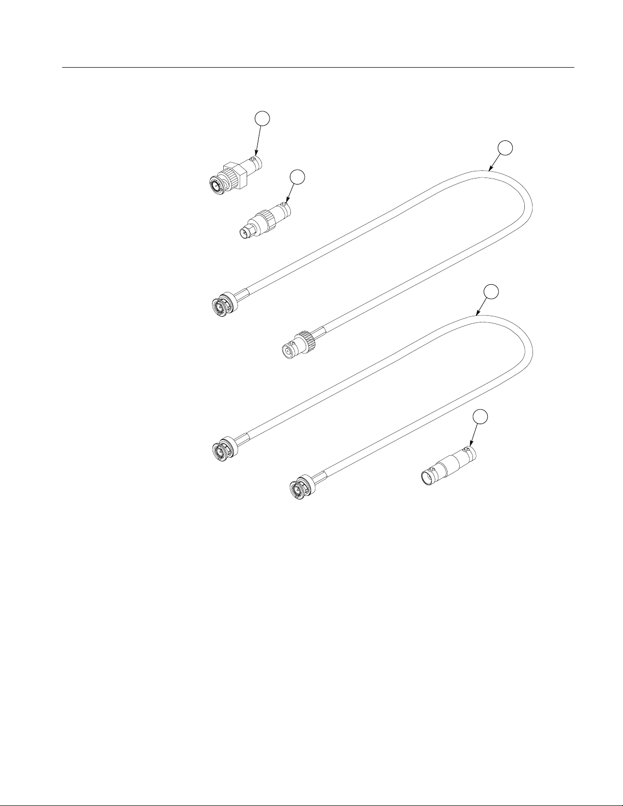
Figure 9: Optional accessories
5
AMT75 Impedance Adapter Instructions
15
Page 20

Performance Verification
Replaceable parts list
Fig. &
index
number
8– Adapter:AMT75
–1 131–3627–01 1 CONTACT,ELEC:GOLD PLATED TIP 18359 P–6158–1
–2 205–0191–00 1 SHELL,ELEC CONN:BNC,ABS,DOVE GRAY 80009 205–0191–00
–3 334–9320–00 1 MARKER,IDENT:INSTRUMENT LABEL, AMT75 80009 334–9320–00
–4 206–0473–00 1 COMP BOX:COMP BOX,TOP,FLINT,AMT75 TK2565 206–0473–00 OBD
–5 206–0474–00 1 COMP BOX:COMP BOX,BOTTOM,FLINT,AMT75 TK2565 206–0474–00 OBD
9–1 011–0049–01 1 TERMN,COAXIAL:50 OHM,2W,BNC 24931 28A123–1
–2 015–0554–00 1 ADPTR,SMA,ELEC:FEMALE BNC TO MALE SMA 24931 29JP170–1
–3 012–0104–00 1 CA ASSY,RF:COAXIAL,RFD,50 OHM,RG58/U,18.0
–4 012–1339–00 1 CA ASSY,RF:COAXIAL,RFD,75 OHM,24 L,
–5 103–0028–00 1 ADAPTER,CONN:BNC,FEMALE TO FEMALE,1.3
Tektronix
part number
070–9479–00 1 MANUAL,TECH:INSTRUCTIONS,XBS,AMT75,DP TK2548 070–9479–00
Serial no.
effective
Serial no.
discont’d
Qty Name & description Mfr. code Mfr. part number
Standard Accessories
Optional Accessories
74868 35001–1
L,MALE,BNC X FEMALE,BNC,
80009 012–1339–00
BNC,MALE,STR,BOTH ENDS,W/STRAIN RELIEF
BOOT BOTH ENDS
24931 28A100–2
L,GOLD/NICKEL
Manufacturers cross index
Mfr.
code
07416 NELSON NAME PLATE COMPANY 3191 CASITAS AVENUE LOS ANGELES, CA 90039–2410
18359 PYLON CO. INC. 51 NEWCOMB ST ATTLEBORO, MA 02703–1403
24931 BERG ELECTRONICS INC BERG ELECTRONICS RF/COAXIAL DIV
74868 AMPHENOL CORP RF/MICROWA VE OPERATIONS
80009 TEKTRONIX INC 14150 SW KARL BRAUN DR
TK2548 XEROX CORPORATION 14181 SW MILLIKAN WAY BEAVERT ON, OR 97005
TK2565 VISION PLASTICS INC 26000 SW PARKWAY CENTER DRIVE WILSONVILLE, OR 97070
Manufacturer Address City , state, zip code
2100 EARLYWOOD DR
PO BOX 547
1 KENNEDY AVE
PO BOX 500
FRANKLIN, IN 46131
DANBURY, CT 06810–5803
BEAVERT ON, OR 97077–0001
16
AMT75 Impedance Adapter Instructions
 Loading...