


Instruction Manual
AM 503B & AM 5030
AC/DC Current Probe Amplifiers
070-8766-05
This document applies for firmware version 3.0
and above.
Warning
The servicing instructions are for use by qualified
personnel only. To avoid personal injury, do not
perform any servicing unless you are qualified to
do so. Refer to the Safety Summary prior to
performing service.

Copyright T ektronix, Inc. 1994. All rights reserved. Licensed software products are owned by Tektronix or its suppliers
and are protected by United States copyright laws and international treaty provisions.
Use, duplication, or disclosure by the Government is subject to restrictions as set forth in subparagraph (c)(1)(ii) of the
Rights in T echnical Data and Computer Software clause at DFARS 252.227-7013, or subparagraphs (c)(1) and (2) of the
Commercial Computer Software – Restricted Rights clause at F AR 52.227-19, as applicable.
T ektronix products are covered by U.S. and foreign patents, issued and pending. Information in this publication supercedes
that in all previously published material. Specifications and price change privileges reserved.
Printed in the U.S.A.
T ektronix, Inc., P.O. Box 1000, Wilsonville, OR 97070–1000
TEKTRONIX and TEK are registered trademarks of T ektronix, Inc.

WARRANTY
T ektronix warrants that this product will be free from defects in materials and workmanship for a period of one (1) year
from the date of shipment. If any such product proves defective during this warranty period, T ektronix, at its option, either
will repair the defective product without charge for parts and labor, or will provide a replacement in exchange for the
defective product.
In order to obtain service under this warranty, Customer must notify Tektronix of the defect before the expiration of the
warranty period and make suitable arrangements for the performance of service. Customer shall be responsible for
packaging and shipping the defective product to the service center designated by T ektronix, with shipping charges prepaid.
T ektronix shall pay for the return of the product to Customer if the shipment is to a location within the country in which the
T ektronix service center is located. Customer shall be responsible for paying all shipping charges, duties, taxes, and any
other charges for products returned to any other locations.
This warranty shall not apply to any defect, failure or damage caused by improper use or improper or inadequate
maintenance and care. T ektronix shall not be obligated to furnish service under this warranty a) to repair damage resulting
from attempts by personnel other than T ektronix representatives to install, repair or service the product; b) to repair
damage resulting from improper use or connection to incompatible equipment; or c) to service a product that has been
modified or integrated with other products when the effect of such modification or integration increases the time or
difficulty of servicing the product.
THIS WARRANTY IS GIVEN BY TEKTRONIX WITH RESPECT TO THIS PRODUCT IN LIEU OF ANY
OTHER WARRANTIES, EXPRESSED OR IMPLIED. TEKTRONIX AND ITS VENDORS DISCLAIM ANY
IMPLIED WARRANTIES OF MERCHANTABILITY OR FITNESS FOR A PARTICULAR PURPOSE.
TEKTRONIX’ RESPONSIBILITY TO REPAIR OR REPLACE DEFECTIVE PRODUCTS IS THE SOLE AND
EXCLUSIVE REMEDY PROVIDED TO THE CUST OMER FOR BREACH OF THIS WARRANTY. TEKTRONIX
AND ITS VENDORS WILL NOT BE LIABLE FOR ANY INDIRECT , SPECIAL, INCIDENTAL, OR
CONSEQUENTIAL DAMAGES IRRESPECTIVE OF WHETHER TEKTRONIX OR THE VENDOR HAS
ADVANCE NOTICE OF THE POSSIBILITY OF SUCH DAMAGES.


EC Declaration of Conformity
We
Tektronix Holland N.V.
Marktweg 73A
8444 AB Heerenveen
The Netherlands
declare under sole responsibility that the
AM503B Current Probe Amplifier
meet the intent of Directive 89/336/EEC for Electromagnetic Compatibility.
Compliance was demonstrated to the following specifications as listed in the Official
Journal of the European Communities:
EN 50081-1 Emissions:
EN 55022 Class B Radiated and Conducted Emissions
EN 60555-2 AC Power Line Harmonic Emissions
EN 50082-1 Immunity:
IEC 801-2 Electrostatic Discharge Immunity
IEC 801-3 RF Electromagnetic Field Immunity
IEC 801-4 Electrical Fast Transient/Burst Immunity
IEC 801-5 Power Line Surge Immunity
This product complies when installed into the following Tektronix instrument
enclosure:
TM502A Power Supply


EC Declaration of Conformity
We
Tektronix Holland N.V.
Marktweg 73A
8444 AB Heerenveen
The Netherlands
declare under sole responsibility that the
AM5030 and AM5030S Current Probe Amplifiers
meet the intent of Directive 89/336/EEC for Electromagnetic Compatibility.
Compliance was demonstrated to the following specifications as listed in the Official
Journal of the European Communities:
EN 55011 Class B Radiated and Conducted Emissions
EN 50081-1 Emissions:
EN 60555-2 AC Power Line Harmonic Emissions
EN 50082-1 Immunity:
IEC 801-2 Electrostatic Discharge Immunity
IEC 801-3 RF Electromagnetic Field Immunity
IEC 801-4 Electrical Fast Transient/Burst Immunity


Table of Contents
Getting Started
Operating Basics
General Safety Summary ix. . . . . . . . . . . . . . . . . . . . . . . . . . . . . . . . . . . .
Service Safety Summary xiii. . . . . . . . . . . . . . . . . . . . . . . . . . . . . . . . . . . . .
Preface xv. . . . . . . . . . . . . . . . . . . . . . . . . . . . . . . . . . . . . . . . . . . . . . . . . . .
Getting Started 1–1. . . . . . . . . . . . . . . . . . . . . . . . . . . . . . . . . . . . . . . . . . . .
Customer Support 1–1. . . . . . . . . . . . . . . . . . . . . . . . . . . . . . . . . . . . . . . . . . . . . . . . .
AM 503B and AM 5030 System Configuration 1–2. . . . . . . . . . . . . . . . . . . . . . . . .
Standard Accessories 1–3. . . . . . . . . . . . . . . . . . . . . . . . . . . . . . . . . . . . . . . . . . . . . .
Optional Accessories 1–3. . . . . . . . . . . . . . . . . . . . . . . . . . . . . . . . . . . . . . . . . . . . . .
Installing the TM Series Power Module 1–4. . . . . . . . . . . . . . . . . . . . . . . . . . . . . . .
Installing the AM 503B or AM 5030 Into the Power Module 1–5. . . . . . . . . . . . . . .
Connecting the Amplifier to an Oscilloscope 1–7. . . . . . . . . . . . . . . . . . . . . . . . . . .
Connecting a Current Probe to the Amplifier 1–8. . . . . . . . . . . . . . . . . . . . . . . . . . .
Measurements 2–1. . . . . . . . . . . . . . . . . . . . . . . . . . . . . . . . . . . . . . . . . . . . .
Operating the Current Probe Slide 2–1. . . . . . . . . . . . . . . . . . . . . . . . . . . . . . . . . . . .
Degaussing and Autobalancing the Current Probe 2–2. . . . . . . . . . . . . . . . . . . . . . .
DC Measurements 2–3. . . . . . . . . . . . . . . . . . . . . . . . . . . . . . . . . . . . . . . . . . . . . . . .
AC Measurements 2–4. . . . . . . . . . . . . . . . . . . . . . . . . . . . . . . . . . . . . . . . . . . . . . . .
Control Summary 2–7. . . . . . . . . . . . . . . . . . . . . . . . . . . . . . . . . . . . . . . . . .
AM 503B and AM 5030 Controls 2–8. . . . . . . . . . . . . . . . . . . . . . . . . . . . . . . . . . . .
AM 5030 GPIB Controls 2–12. . . . . . . . . . . . . . . . . . . . . . . . . . . . . . . . . . . . . . . . . . .
GPIB Operation 2–13. . . . . . . . . . . . . . . . . . . . . . . . . . . . . . . . . . . . . . . . . . . .
GPIB Requirements 2–14. . . . . . . . . . . . . . . . . . . . . . . . . . . . . . . . . . . . . . . . . . . . . . .
Setting the GPIB Parameters 2–14. . . . . . . . . . . . . . . . . . . . . . . . . . . . . . . . . . . . . . . .
Other Documents You Will Need 2–15. . . . . . . . . . . . . . . . . . . . . . . . . . . . . . . . . . . . .
Functional Command Groups 2–17. . . . . . . . . . . . . . . . . . . . . . . . . . . . . . . .
Front Panel Commands 2–17. . . . . . . . . . . . . . . . . . . . . . . . . . . . . . . . . . . . . . . . . . . .
GPIB Status Commands 2–18. . . . . . . . . . . . . . . . . . . . . . . . . . . . . . . . . . . . . . . . . . . .
Amplifier Status Commands 2–18. . . . . . . . . . . . . . . . . . . . . . . . . . . . . . . . . . . . . . . .
Probe Status Commands 2–19. . . . . . . . . . . . . . . . . . . . . . . . . . . . . . . . . . . . . . . . . . .
Commands 2–21. . . . . . . . . . . . . . . . . . . . . . . . . . . . . . . . . . . . . . . . . . . . . . . .
ALLEve? (Query Only) 2–21. . . . . . . . . . . . . . . . . . . . . . . . . . . . . . . . . . . . . . . . . . . .
AMPS 2–21. . . . . . . . . . . . . . . . . . . . . . . . . . . . . . . . . . . . . . . . . . . . . . . . . . . . . . . . . .
BWLIMit 2–22. . . . . . . . . . . . . . . . . . . . . . . . . . . . . . . . . . . . . . . . . . . . . . . . . . . . . . .
COUpling 2–22. . . . . . . . . . . . . . . . . . . . . . . . . . . . . . . . . . . . . . . . . . . . . . . . . . . . . . .
DCLEVel 2–23. . . . . . . . . . . . . . . . . . . . . . . . . . . . . . . . . . . . . . . . . . . . . . . . . . . . . . .
DEGAuss (No Query Form) 2–23. . . . . . . . . . . . . . . . . . . . . . . . . . . . . . . . . . . . . . . .
ERRor? (Query Only) 2–24. . . . . . . . . . . . . . . . . . . . . . . . . . . . . . . . . . . . . . . . . . . . .
EVent? (Query Only) 2–24. . . . . . . . . . . . . . . . . . . . . . . . . . . . . . . . . . . . . . . . . . . . . .
EXit 2–24. . . . . . . . . . . . . . . . . . . . . . . . . . . . . . . . . . . . . . . . . . . . . . . . . . . . . . . . . . .
FPLock 2–25. . . . . . . . . . . . . . . . . . . . . . . . . . . . . . . . . . . . . . . . . . . . . . . . . . . . . . . . .
AM 503B & AM 5030 Amplifier Instruction Manual
i

Contents
Reference
HELp? (Query Only) 2–25. . . . . . . . . . . . . . . . . . . . . . . . . . . . . . . . . . . . . . . . . . . . . .
ID? (Query Only) 2–26. . . . . . . . . . . . . . . . . . . . . . . . . . . . . . . . . . . . . . . . . . . . . . . . .
INIT (No Query Form) 2–26. . . . . . . . . . . . . . . . . . . . . . . . . . . . . . . . . . . . . . . . . . . .
OVerload? (Query Only) 2–26. . . . . . . . . . . . . . . . . . . . . . . . . . . . . . . . . . . . . . . . . . .
PATH 2–27. . . . . . . . . . . . . . . . . . . . . . . . . . . . . . . . . . . . . . . . . . . . . . . . . . . . . . . . . .
PROBEOPen? (Query Only) 2–27. . . . . . . . . . . . . . . . . . . . . . . . . . . . . . . . . . . . . . . .
PROBETRim 2–28. . . . . . . . . . . . . . . . . . . . . . . . . . . . . . . . . . . . . . . . . . . . . . . . . . . .
PROBETYpe? (Query Only) 2–29. . . . . . . . . . . . . . . . . . . . . . . . . . . . . . . . . . . . . . . .
RQS 2–29. . . . . . . . . . . . . . . . . . . . . . . . . . . . . . . . . . . . . . . . . . . . . . . . . . . . . . . . . . .
SERIAL? (Query Only) 2–30. . . . . . . . . . . . . . . . . . . . . . . . . . . . . . . . . . . . . . . . . . . .
SET? (Query Only) 2–30. . . . . . . . . . . . . . . . . . . . . . . . . . . . . . . . . . . . . . . . . . . . . . .
TEST (No Query Form) 2–31. . . . . . . . . . . . . . . . . . . . . . . . . . . . . . . . . . . . . . . . . . . .
UNIts? (Query Only) 2–31. . . . . . . . . . . . . . . . . . . . . . . . . . . . . . . . . . . . . . . . . . . . . .
Error Messages & Codes 2–33. . . . . . . . . . . . . . . . . . . . . . . . . . . . . . . . . . . .
Reference Notes 3–1. . . . . . . . . . . . . . . . . . . . . . . . . . . . . . . . . . . . . . . . . . . .
Degaussing a Probe with an Unpowered Conductor in the Jaws 3–1. . . . . . . . . . . . .
Bandwidth Limiting 3–2. . . . . . . . . . . . . . . . . . . . . . . . . . . . . . . . . . . . . . . . . . . . . . .
Measuring Differential Current 3–2. . . . . . . . . . . . . . . . . . . . . . . . . . . . . . . . . . . . . .
AC and DC Coupling 3–3. . . . . . . . . . . . . . . . . . . . . . . . . . . . . . . . . . . . . . . . . . . . . .
Maximum Current Limits 3–4. . . . . . . . . . . . . . . . . . . . . . . . . . . . . . . . . . . . . . . . . .
Extending Current Range 3–5. . . . . . . . . . . . . . . . . . . . . . . . . . . . . . . . . . . . . . . . . . .
Increasing Sensitivity 3–7. . . . . . . . . . . . . . . . . . . . . . . . . . . . . . . . . . . . . . . . . . . . . .
Application Notes 3–9. . . . . . . . . . . . . . . . . . . . . . . . . . . . . . . . . . . . . . . . . . .
Automobile Charging Systems 3–9. . . . . . . . . . . . . . . . . . . . . . . . . . . . . . . . . . . . . .
Inductance Measurements 3–11. . . . . . . . . . . . . . . . . . . . . . . . . . . . . . . . . . . . . . . . . .
Continuity T est of Multiple-Conductor Cable 3–14. . . . . . . . . . . . . . . . . . . . . . . . . . .
Measuring Inductor Turns Count 3–14. . . . . . . . . . . . . . . . . . . . . . . . . . . . . . . . . . . . .
Error Codes 3–17. . . . . . . . . . . . . . . . . . . . . . . . . . . . . . . . . . . . . . . . . . . . . . .
Troubleshooting 3–19. . . . . . . . . . . . . . . . . . . . . . . . . . . . . . . . . . . . . . . . . . . .
Specifications
Specifications 4–1. . . . . . . . . . . . . . . . . . . . . . . . . . . . . . . . . . . . . . . . . . . . . .
Warranted Specifications 4–2. . . . . . . . . . . . . . . . . . . . . . . . . . . . . . . . . . . . . . . . . . .
Nominal and T ypical Characteristics 4–2. . . . . . . . . . . . . . . . . . . . . . . . . . . . . . . . . .
Environmental Characteristics 4–4. . . . . . . . . . . . . . . . . . . . . . . . . . . . . . . . . . . . . . .
Performance Verification
Performance Verification Setup 5–1. . . . . . . . . . . . . . . . . . . . . . . . . . . . . . .
T est Procedure Conditions 5–1. . . . . . . . . . . . . . . . . . . . . . . . . . . . . . . . . . . . . . . . . .
Equipment Preparation 5–1. . . . . . . . . . . . . . . . . . . . . . . . . . . . . . . . . . . . . . . . . . . . .
W arranted Specifications 5–2. . . . . . . . . . . . . . . . . . . . . . . . . . . . . . . . . . . . . . . . . . .
Performance Verification with an A6312 5–3. . . . . . . . . . . . . . . . . . . . . . .
Required Test Equipment 5–3. . . . . . . . . . . . . . . . . . . . . . . . . . . . . . . . . . . . . . . . . . .
Bandwidth 5–5. . . . . . . . . . . . . . . . . . . . . . . . . . . . . . . . . . . . . . . . . . . . . . . . . . . . . .
Rise Time 5–7. . . . . . . . . . . . . . . . . . . . . . . . . . . . . . . . . . . . . . . . . . . . . . . . . . . . . . .
DC Gain Accuracy 5–9. . . . . . . . . . . . . . . . . . . . . . . . . . . . . . . . . . . . . . . . . . . . . . . .
ii
AM 503B & AM 5030 Amplifier Instruction Manual

Adjustment Procedures
Contents
Performance Verification with an A6302 or A6302XL 5–15. . . . . . . . . . . .
Required Test Equipment 5–15. . . . . . . . . . . . . . . . . . . . . . . . . . . . . . . . . . . . . . . . . . .
Bandwidth 5–17. . . . . . . . . . . . . . . . . . . . . . . . . . . . . . . . . . . . . . . . . . . . . . . . . . . . . .
Rise Time 5–19. . . . . . . . . . . . . . . . . . . . . . . . . . . . . . . . . . . . . . . . . . . . . . . . . . . . . . .
DC Gain Accuracy 5–21. . . . . . . . . . . . . . . . . . . . . . . . . . . . . . . . . . . . . . . . . . . . . . . .
Performance Verification with an A6303 or A6303XL 5–27. . . . . . . . . . . .
Required Test Equipment 5–27. . . . . . . . . . . . . . . . . . . . . . . . . . . . . . . . . . . . . . . . . . .
Bandwidth 5–28. . . . . . . . . . . . . . . . . . . . . . . . . . . . . . . . . . . . . . . . . . . . . . . . . . . . . .
Rise Time 5–30. . . . . . . . . . . . . . . . . . . . . . . . . . . . . . . . . . . . . . . . . . . . . . . . . . . . . . .
DC Gain Accuracy 5–32. . . . . . . . . . . . . . . . . . . . . . . . . . . . . . . . . . . . . . . . . . . . . . . .
Performance Verification with an A6304XL 5–37. . . . . . . . . . . . . . . . . . . .
Required Test Equipment 5–37. . . . . . . . . . . . . . . . . . . . . . . . . . . . . . . . . . . . . . . . . . .
Rise Time 5–38. . . . . . . . . . . . . . . . . . . . . . . . . . . . . . . . . . . . . . . . . . . . . . . . . . . . . . .
Bandwidth 5–40. . . . . . . . . . . . . . . . . . . . . . . . . . . . . . . . . . . . . . . . . . . . . . . . . . . . . .
DC Gain Accuracy 5–40. . . . . . . . . . . . . . . . . . . . . . . . . . . . . . . . . . . . . . . . . . . . . . . .
Adjustment Procedures for Current Probes 6–1. . . . . . . . . . . . . . . . . . . . .
A6312, A6302 and A6302XL Adjustment 6–3. . . . . . . . . . . . . . . . . . . . . . .
Required Test Equipment 6–3. . . . . . . . . . . . . . . . . . . . . . . . . . . . . . . . . . . . . . . . . . .
A6312, A6302 and A6302XL DC Offset Adjustment 6–3. . . . . . . . . . . . . . . . . . . . .
A6303 and A6303XL Adjustments 6–7. . . . . . . . . . . . . . . . . . . . . . . . . . . .
Required Test Equipment 6–7. . . . . . . . . . . . . . . . . . . . . . . . . . . . . . . . . . . . . . . . . . .
A6303 and A6303XL DC Offset Adjustment 6–8. . . . . . . . . . . . . . . . . . . . . . . . . . .
A6303 and A6303XL Transient Response and Gain Adjustment 6–10. . . . . . . . . . . .
A6304XL Adjustments 6–13. . . . . . . . . . . . . . . . . . . . . . . . . . . . . . . . . . . . . .
Required Test Equipment 6–13. . . . . . . . . . . . . . . . . . . . . . . . . . . . . . . . . . . . . . . . . . .
A6304XL DC Offset Adjustment 6–14. . . . . . . . . . . . . . . . . . . . . . . . . . . . . . . . . . . .
DC Gain Adjustment 6–16. . . . . . . . . . . . . . . . . . . . . . . . . . . . . . . . . . . . . . . . . . . . . .
A6304XL Transient Response Adjustment 6–18. . . . . . . . . . . . . . . . . . . . . . . . . . . . .
Maintenance
Customer Maintenance 7–1. . . . . . . . . . . . . . . . . . . . . . . . . . . . . . . . . . . . . .
Service Strategy 7–1. . . . . . . . . . . . . . . . . . . . . . . . . . . . . . . . . . . . . . . . . . . . . . . . . .
Preventive Maintenance 7–1. . . . . . . . . . . . . . . . . . . . . . . . . . . . . . . . . . . . . . . . . . . .
Disassembly 7–3. . . . . . . . . . . . . . . . . . . . . . . . . . . . . . . . . . . . . . . . . . . . . . .
Static Device Precautions 7–3. . . . . . . . . . . . . . . . . . . . . . . . . . . . . . . . . . . . . . . . . . .
Front Panel Knobs 7–4. . . . . . . . . . . . . . . . . . . . . . . . . . . . . . . . . . . . . . . . . . . . . . . .
Side Covers 7–4. . . . . . . . . . . . . . . . . . . . . . . . . . . . . . . . . . . . . . . . . . . . . . . . . . . . .
Front Panel and Release Lever Assembly 7–4. . . . . . . . . . . . . . . . . . . . . . . . . . . . . .
Front Panel Disassembly 7–7. . . . . . . . . . . . . . . . . . . . . . . . . . . . . . . . . . . . . . . . . . .
Using the Rear Interface Output Connector 7–8. . . . . . . . . . . . . . . . . . . . . . . . . . . . .
Battery Replacement 7–10. . . . . . . . . . . . . . . . . . . . . . . . . . . . . . . . . . . . . . . . . . . . . .
Replaceable Mechanical Parts
Replaceable Parts 8–1. . . . . . . . . . . . . . . . . . . . . . . . . . . . . . . . . . . . . . . . . .
Parts Ordering Information 8–1. . . . . . . . . . . . . . . . . . . . . . . . . . . . . . . . . . . . . . . . .
Using the Replaceable Parts List 8–1. . . . . . . . . . . . . . . . . . . . . . . . . . . . . . . . . . . . .
AM 503B & AM 5030 Amplifier Instruction Manual
iii

Contents
Glossary and Index
iv
AM 503B & AM 5030 Amplifier Instruction Manual

List of Figures
Contents
Figure 1–1: Configuring the AM 503B and AM 5030 Current
Measurement System 1–2. . . . . . . . . . . . . . . . . . . . . . . . . . . . . . . . . . . .
Figure 1–2: TM Series Power Module Voltage Selector 1–4. . . . . . . . . . .
Figure 1–3: Changing the TM 502A Operating Voltage 1–5. . . . . . . . . . .
Figure 1–4: Installing the AM 503B and AM 5030 into the
Power Module 1–6. . . . . . . . . . . . . . . . . . . . . . . . . . . . . . . . . . . . . . . . . .
Figure 1–5: Connecting a Current Probe to the Amplifier 1–8. . . . . . . . .
Figure 2–1: A6312, A6302, and A6302XL Slide Operation 2–1. . . . . . . . .
Figure 2–2: A6303, A6303XL, and A6304XL Slide Operation 2–2. . . . . .
Figure 2–3: Current Probe Polarity 2–4. . . . . . . . . . . . . . . . . . . . . . . . . . . .
Figure 2–4: The AM 503B and AM 5030 Front Panel 2–7. . . . . . . . . . . . .
Figure 2–5: Stacked GPIB Connectors 2–13. . . . . . . . . . . . . . . . . . . . . . . . .
Figure 2–6: Typical GPIB Network Configurations 2–14. . . . . . . . . . . . . .
Figure 3–1: Measuring Differential Current and Nulls 3–2. . . . . . . . . . . .
Figure 3–2: Effect of AC or DC Coupling on Low-Frequency Signals 3–3
Figure 3–3: Applying the Amp-Second Product Rule 3–5. . . . . . . . . . . . .
Figure 3–4: Increasing the DC Measurement Range 3–6. . . . . . . . . . . . . .
Figure 3–5: Increasing Probe Sensitivity 3–7. . . . . . . . . . . . . . . . . . . . . . . .
Figure 3–6: Setup for Measuring Charging Current 3–10. . . . . . . . . . . . . .
Figure 3–7: Charge Current Waveforms 3–10. . . . . . . . . . . . . . . . . . . . . . .
Figure 3–8: Measuring Inductance with a Low-Impedance Source 3–11. .
Figure 3–9: Linear Current vs. Time Ramp 3–12. . . . . . . . . . . . . . . . . . . . .
Figure 3–10: Measuring Inductance with a High-Impedance Source 3–13
Figure 3–11: High-Impedance Source Current Ramp 3–13. . . . . . . . . . . . .
Figure 3–12: Measuring the Number of Turns in a Coil 3–14. . . . . . . . . . .
Figure 3–13: Turns Measurement Using Reference Coil 3–15. . . . . . . . . . .
Figure 5–1: Bandwidth Test Setup for A6312 5–5. . . . . . . . . . . . . . . . . . . .
Figure 5–2: Rise Time Test Setup for A6312 5–7. . . . . . . . . . . . . . . . . . . .
Figure 5–3: DC Gain Accuracy Test Setup for A6312 5–10. . . . . . . . . . . . .
Figure 5–4: Bandwidth Test Setup for A6302/A6302XL 5–17. . . . . . . . . . .
Figure 5–5: Rise Time Test Setup for A6302/A6302XL 5–19. . . . . . . . . . . .
Figure 5–6: DC Gain Accuracy Test Setup for A6302/A6302XL 5–22. . . .
Figure 5–7: Bandwidth Test Setup for an A6303/A6303XL 5–28. . . . . . . .
AM 503B & AM 5030 Amplifier Instruction Manual
v

Contents
Figure 5–8: Rise Time Test Setup for A6303/A6303XL 5–30. . . . . . . . . . . .
Figure 5–9: DC Gain Accuracy Test Setup for A6303/A6303XL 5–33. . . .
Figure 5–10: Rise Time Test Setup for the A6304XL 5–38. . . . . . . . . . . . . .
Figure 5–11: DC Gain Accuracy Test Setup for the A6304XL 5–41. . . . . .
Figure 6–1: A6312, A6302 and A6302XL DC Offset Adjustment
Location 6–3. . . . . . . . . . . . . . . . . . . . . . . . . . . . . . . . . . . . . . . . . . . . . . .
Figure 6–2: A6303 and A6303XL Adjustment Locations 6–8. . . . . . . . . .
Figure 6–3: A6303 and A6303XL Adjustment Setup 6–11. . . . . . . . . . . . . .
Figure 6–4: A6304XL Adjustment Locations 6–15. . . . . . . . . . . . . . . . . . . .
Figure 6–5: DC Gain Accuracy Adjustment Setup 6–17. . . . . . . . . . . . . . .
Figure 6–6: A6304XL Adjustment Setup 6–18. . . . . . . . . . . . . . . . . . . . . . .
Figure 7–1: Removing the AM 503B and AM 5030 Side Covers 7–4. . . .
Figure 7–2: Removing the Amplifier Release Lever 7–5. . . . . . . . . . . . . .
Figure 7–3: Location of Amplifier Interface Cables 7–5. . . . . . . . . . . . . .
Figure 7–4: Location of Front Panel Screws 7–6. . . . . . . . . . . . . . . . . . . . .
Figure 7–5: Removing the Latch Bar Assembly 7–6. . . . . . . . . . . . . . . . . .
Figure 7–6: Removing the Amplifier Output Connector 7–7. . . . . . . . . . .
Figure 7–7: Removing the Amplifier Front Panel Board 7–8. . . . . . . . . .
Figure 7–8: Using the Rear Interface Output Connector 7–9. . . . . . . . . .
Figure 7–9: Prying Battery Terminal to Remove Battery 7–10. . . . . . . . . .
Figure 7–10: Removing the Backup Battery 7–10. . . . . . . . . . . . . . . . . . . . .
Figure 7–11: Replacing the Backup Battery 7–11. . . . . . . . . . . . . . . . . . . . .
Figure 8–1: AM 503B & AM 5030 Replaceable Parts 8–3. . . . . . . . . . . . .
Figure 8–2: AM 503B & AM 5030 Standard Accessories 8–6. . . . . . . . . .
vi
AM 503B & AM 5030 Amplifier Instruction Manual

List of Tables
Contents
Table 2–1: Front Panel Commands 2–17. . . . . . . . . . . . . . . . . . . . . . . . . . .
Table 2–2: GPIB Status Commands 2–18. . . . . . . . . . . . . . . . . . . . . . . . . . .
Table 2–3: Amplifier Status Commands 2–18. . . . . . . . . . . . . . . . . . . . . . .
Table 2–4: Probe Status Commands 2–19. . . . . . . . . . . . . . . . . . . . . . . . . . .
Table 2–5: AM 5030 Event Codes 2–33. . . . . . . . . . . . . . . . . . . . . . . . . . . . .
Table 3–1: Unpowered Circuit Degauss Limits 3–1. . . . . . . . . . . . . . . . . .
Table 3–2: Automobile Charging Systems Test Setup 3–9. . . . . . . . . . . . .
Table 3–3: AM 503B and AM 5030 Front-Panel Error Codes 3–18. . . . . .
Table 3–4: Troubleshooting 3–19. . . . . . . . . . . . . . . . . . . . . . . . . . . . . . . . . .
Table 4–1: Warranted AM 503B and AM 5030 Specifications 4–2. . . . .
Table 4–2: Nominal and Typical AM 503B and AM 5030
Characteristics 4–2. . . . . . . . . . . . . . . . . . . . . . . . . . . . . . . . . . . . . . . . .
Table 4–3: AM 503B and AM 5030 Mechanical Characteristics 4–3. . . .
Table 4–4: AM 503B and AM 5030 Environmental Characteristics 4–4.
Table 5–1: Required Test Equipment 5–4. . . . . . . . . . . . . . . . . . . . . . . . . .
Table 5–2: Equipment Settings for Bandwidth 5–5. . . . . . . . . . . . . . . . . .
Table 5–3: Equipment Settings for Rise Time 5–8. . . . . . . . . . . . . . . . . . .
Table 5–4: Equipment Settings for DC Gain Accuracy 5–10. . . . . . . . . . .
Table 5–5: DC Gain Accuracy Test for A6312 5–11. . . . . . . . . . . . . . . . . . .
Table 5–6: DC Gain Accuracy Test Worksheet for A6312 5–13. . . . . . . . .
Table 5–7: Required Test Equipment 5–16. . . . . . . . . . . . . . . . . . . . . . . . . .
Table 5–8: Equipment Settings for Bandwidth 5–17. . . . . . . . . . . . . . . . . .
Table 5–9: Equipment Settings for Rise Time 5–20. . . . . . . . . . . . . . . . . . .
Table 5–10: Equipment Settings for DC Gain Accuracy 5–22. . . . . . . . . .
Table 5–11: DC Gain Accuracy Test for A6302/A6302XL 5–23. . . . . . . . .
Table 5–12: DC Gain Accuracy Test Worksheet for A6302/A6302XL 5–25
Table 5–13: Required Test Equipment 5–27. . . . . . . . . . . . . . . . . . . . . . . . .
Table 5–14: Equipment Settings for Bandwidth 5–29. . . . . . . . . . . . . . . . .
Table 5–15: Equipment Settings for Rise Time 5–31. . . . . . . . . . . . . . . . . .
Table 5–16: Equipment Settings for DC Gain Accuracy 5–32. . . . . . . . . .
Table 5–17: DC Gain Accuracy Test for A6303/A6303XL 5–34. . . . . . . . .
Table 5–18: DC Gain Accuracy Test Work Sheet for
A6303/A6303XL 5–36. . . . . . . . . . . . . . . . . . . . . . . . . . . . . . . . . . . . . . . .
Table 5–19: Required Test Equipment 5–37. . . . . . . . . . . . . . . . . . . . . . . . .
Table 5–20: Equipment Settings for Rise Time 5–39. . . . . . . . . . . . . . . . . .
AM 503B & AM 5030 Amplifier Instruction Manual
vii

Contents
Table 5–21: Equipment Settings for DC Gain Accuracy 5–41. . . . . . . . . .
Table 5–22: DC Gain Accuracy Test for the A6304XL 5–43. . . . . . . . . . . .
Table 5–23: DC Gain Accuracy Test Work Sheet for the A6304XL 5–44.
Table 6–1: Required Test Equipment 6–3. . . . . . . . . . . . . . . . . . . . . . . . . .
Table 6–2: Settings for DC Offset Adjustment 6–4. . . . . . . . . . . . . . . . . .
Table 6–3: Error Codes Requiring DC Offset Adjustment 6–5. . . . . . . .
Table 6–4: Required Test Equipment 6–7. . . . . . . . . . . . . . . . . . . . . . . . . .
Table 6–5: Settings for DC Offset Adjustment 6–9. . . . . . . . . . . . . . . . . .
Table 6–6: Error Codes Requiring DC Offset Adjustment 6–9. . . . . . . .
Table 6–7: Settings for Transient Response and Gain Adjustments 6–11.
Table 6–8: Required Test Equipment 6–13. . . . . . . . . . . . . . . . . . . . . . . . . .
Table 6–9: Settings for DC Offset Adjustment 6–14. . . . . . . . . . . . . . . . . .
Table 6–10: Error Codes Requiring DC Offset Adjustment 6–15. . . . . . .
Table 6–11: Equipment Settings for DC Gain Accuracy 6–16. . . . . . . . . .
Table 6–12: Equipment Settings for Transient Response 6–18. . . . . . . . . .
viii
AM 503B & AM 5030 Amplifier Instruction Manual

General Safety Summary
Review the following safety precautions to avoid injury and prevent damage to
this product or any products connected to it.
Only qualified personnel should perform service procedures.
While using this product, you may need to access other parts of the system. Read
the General Safety Summary in other system manuals for warnings and cautions
related to operating the system.
Injury Precautions
Ground the Product
Do Not Operate Without
Covers
Do Not Operate in
Wet/Damp Conditions
Do Not Operate in
Explosive Atmosphere
Avoid Exposed Circuitry
This product is grounded through the grounding conductor of the power cord. To
avoid electric shock, the grounding conductor must be connected to earth
ground. Before making connections to the input or output terminals of the
product, ensure that the product is properly grounded.
To avoid electric shock or fire hazard, do not operate this product with covers or
panels removed.
To avoid electric shock, do not operate this product in wet or damp conditions.
To avoid injury or fire hazard, do not operate this product in an explosive
atmosphere.
To avoid injury, remove jewelry such as rings, watches, and other metallic
objects. Do not touch exposed connections and components when power is
present.
AM 503B & AM 5030 Amplifier Instruction Manual
ix

General Safety Summary
Product Damage Precautions
Use Proper Power Source
Use Proper Voltage
Setting
Provide Proper Ventilation
Do Not Operate With
Suspected Failures
Do not operate this product from a power source that applies more than the
voltage specified.
Before applying power, ensure that the line selector is in the proper position for
the power source being used.
To prevent product overheating, provide proper ventilation.
If you suspect there is damage to this product, have it inspected by qualified
service personnel.
Safety Terms and Symbols
Terms in This Manual
These terms may appear in this manual:
WARNING. Warning statements identify conditions or practices that could result
in injury or loss of life.
Terms on the Product
x
CAUTION. Caution statements identify conditions or practices that could result in
damage to this product or other property.
These terms may appear on the product:
DANGER indicates an injury hazard immediately accessible as you read the
marking.
WARNING indicates an injury hazard not immediately accessible as you read the
marking.
CAUTION indicates a hazard to property including the product.
AM 503B & AM 5030 Amplifier Instruction Manual

General Safety Summary
Symbols on the Product
The following symbols may appear on the product:
DANGER
High Voltage
Certifications and Compliances
CSA Certified Power
Cords
Safety Certification of
Plug-in Modules
CSA Certification includes the products and power cords appropriate for use in
the North America power network. All other power cords supplied are approved
for the country of use.
For plug-in modules that are safety certified by Underwriters Laboratories, UL
Listing applies only when the module is installed in a UL Listed product. CSA
Certification applies only when the module is installed in a CSA Certified
product.
Protective Ground
(Earth) T erminal
ATTENTION
Refer to Manual
Double
Insulated
AM 503B & AM 5030 Amplifier Instruction Manual
xi

General Safety Summary
xii
AM 503B & AM 5030 Amplifier Instruction Manual

Service Safety Summary
Only qualified personnel should perform service procedures. Read this Service
Safety Summary and the General Safety Summary before performing any service
procedures.
Do Not Service Alone
Disconnect Power
Use Care When Servicing
With Power On
Do not perform internal service or adjustments of this product unless another
person capable of rendering first aid and resuscitation is present.
To avoid electric shock, disconnect the main power by means of the power cord
or, if provided, the power switch.
Dangerous voltages or currents may exist in this product. Disconnect power,
remove battery (if applicable), and disconnect test leads before removing
protective panels, soldering, or replacing components.
To avoid electric shock, do not touch exposed connections.
AM 503B & AM 5030 Amplifier Instruction Manual
xiii

Service Safety Summary
xiv
AM 503B & AM 5030 Amplifier Instruction Manual

Preface
This Instruction Manual supports the operation and basic maintenance of the
AM 503B and AM 5030 Current Probe Amplifiers.
If you are not familiar with this product, please refer to the Getting Started and
Operating Basics chapters of this manual for basic operating information.
If you are an advanced user, the Reference section contains information on
advanced applications as well as user diagnostic and troubleshooting information.
The Performance Verification and Adjustment Procedure sections support the
qualification and calibration of the probes when used with either amplifier.
NOTE. Except for the A6303, once a probe has been calibrated, it can be used
with any other AM 503B or AM 5030 without readjustment.
The Maintenance section supports the routine maintenance and repair of
mechanical parts associated with the amplifiers.
Related Manuals
Manual Conventions
The Glossary and Index are provided as quick reference locators for important
information.
You can find the documentation supporting the maintenance and repair of the
current probes in the following manuals:
H A6312 Instructions
H A6302 & A6302XL Instructions
H A6303 & A6303XL Instructions
H A6304XL Instructions
The term “Amplifier” is used to refer to either the AM 503B or AM 5030 when
referring to common attributes. If a subject is unique to either amplifier, the
amplifier will be referred to directly by model.
AM 503B & AM 5030 Amplifier Instruction Manual
xv

Preface
xvi
AM 503B & AM 5030 Amplifier Instruction Manual

Getting Started


Getting Started
The AM 503B and AM 5030 current probe amplifiers let you use one probe to
simultaneously measure AC and DC current. The Amplifier converts the sensed
current into a proportional voltage signal that you can measure directly with an
oscilloscope.
The AM 503B and AM 5030 provide better linearity than other current
measurement systems because of a current feedback process used with the probe.
DC measurement capability and high bandwidth allow the Amplifier to
accurately represent square waves and fast-rise signals.
The AM 503B and AM 5030 provide these features:
H Simultaneous DC and AC current measurements.
H High sensitivity.
H One-button autobalancing and probe degaussing.
H No adjustments needed to match a current probe to an individual amplifier
(except for the A6303 current probe).
Customer Support
Operational Support
Service Support
H Probe trim adjust allows fine tuning of gain for increased accuracy.
The AM 5030 provides an additional feature:
H Programmable control from a GPIB controller.
To help you get the best performance from your Amplifier, Tektronix offers the
following customer support services.
If you need assistance operating your amplifier system, please call our Customer
Support Center at 1-800-TEK-WIDE
are outside the United States or Canada, please contact your nearest Tektronix
Service Center.
Should your Amplifier system need repair beyond that described in this manual,
please contact your nearest Tektronix Service Center.
(1-800-835-9433), extension 2400. If you
AM 503B & AM 5030 Amplifier Instruction Manual 1–1
Getting Started
Sales Support
To order optional equipment and accessories, call the Tektronix National
Marketing Center at 1-800-426-2200. If you are outside the United States or
Canada, please contact your nearest Tektronix Service Center.
AM 503B and AM 5030 System Configuration
A complete AM 503B or AM 5030 current measurement system consists of a
current probe amplifier, a compatible current probe, a TM 500 or TM 5000 series
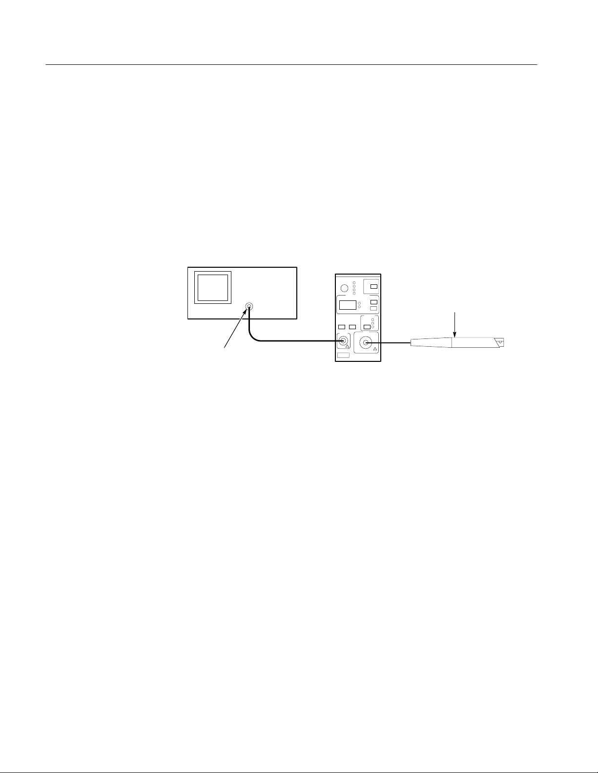
power module, and an appropriate oscilloscope. Refer to Figure 1–1.
Test Oscilloscope
Output
50 oscilloscope input (or add 50
termination here if oscilloscope has
only high-impedance input).
Amplifier in TM Series
Power Module
Current Probe
Input
AM 503B & AM 5030
Current Probe Amplifier
Current Probes
Figure 1–1: Configuring the AM 503B and AM5030 Current Measurement System
The AM 503B is a single-width instrument that plugs into any Tektronix
TM 500 or TM 5000 series power module. The AM 5030 is a single-width
instrument that plugs into any Tektronix TM 5000 series power module. The
Amplifier amplifies the current sensed by the probe and converts the current to a
proportional voltage that is displayed on an oscilloscope or other similar
measuring device.
The AM 503B and AM 5030 systems may be used with the following Tektronix
probes:
H A6312 (20 amps)
H A6302 and A6302XL (20 amps)
H A6303 and A6303XL (100 amps)
H A6304XL (500 amps)
You can also use the CT-4 High-Current Transformer with the A6312, A6302,
and A6302XL current probes to extend their AC current measurement range to
20,000 peak amps.
1–2 AM 503B & AM 5030 Amplifier Instruction Manual

Getting Started
TM 500 Series Power
Modules
TM 5000 Series Power
Module
Oscilloscope
Standard Accessories
The AM 503B operates in a Tektronix TM 500 or TM 5000 series power module
that powers one or more TM 500 series instruments. The Power Module operates
on either 110 or 220 VAC, 50 or 60 Hz.
The AM 5030 operates in a Tektronix TM 5000 series power module that powers
one or more TM 5000 series instruments while providing GPIB support. The
Power Module operates on either 110 or 220 VAC, 50 or 60 Hz.
An oscilloscope displays the output from the current measuring system. A 50
cable is included to connect the Amplifier to the oscilloscope input channel.
If the oscilloscope does not have an input that can be set to 50 impedance, you
need a feedthrough 50 termination. This termination is included as a standard
accessory with your AM 503B and AM 5030 Current Probe Amplifier.
These accessories are shipped with either the AM 503B or AM 5030:
H 50 coaxial cable
Optional Accessories
H 50 feedthrough termination
H Instruction Manual
H Reference card
If you ordered an AM 503S system, you will have received these items:
H AM 503B
H Current Probe (specific probe type depends on option ordered with the
Amplifier)
H TM 502A Power Module
H Toolbox
H AC Power cord
You can order the following optional accessories for the AM 503B and
AM 5030 Current Probe Amplifiers. Refer to the Replaceable Parts List on page
8–6 for Tektronix part numbers to use in ordering these accessories.
AM 503B & AM 5030 Amplifier Instruction Manual 1–3

Getting Started
H One-turn 50 current loop. The current loop is used in the performance
verification procedure for checking the performance of the AM 503B and
AM 5030.
H If you need to measure high-amplitude AC currents, consider using a
Tektronix CT-4 High-Current Transformer with the A6312, A6302, or
A6302XL probes. The CT-4 provides step-down ratios of 20:1 or 1000:1.
For more information about the CT-4, consult your Tektronix sales representative.
Installing the TM Series Power Module
If you ordered your current probe amplifier as a part of a system, a power
module will have been provided. Follow these instructions for the proper setup
and installation of the power module.
The TM Series Power Module can operate from one of four AC line voltages.
The operating voltage is determined by the voltage selector, located on the rear
panel of the TM Series Power Module, as shown in Figure 1–2.
WARNING. To avoid personal injury or equipment damage, do not connect the
power module to the AC line receptacle or turn the power module on until you
have verified that the proper operating voltage is selected.
Voltage Selector
Selector Window
Latch
TM Series
Power Module
Figure 1–2: TM Series Power Module Voltage Selector
1–4 AM 503B & AM 5030 Amplifier Instruction Manual

Getting Started
The value displayed in the voltage selector window should match the value of
your line voltage. If the two values don’t match, perform these steps to select the
correct value:
1. Push up on the latch and pull the voltage selector assembly out.
2. Disassemble the voltage selector as shown in Figure 1–3.
3. Rotate the fuse block until the proper voltage appears in the window.
4. Reassemble the voltage selector and push it back into the power module
until it snaps into place.
5. Using the correct power cord, connect the power module to the AC line
receptacle.
Rotate fuse block so that
the correct voltage
appears in the window
Fuse Block
Selector Window
Figure 1–3: Changing the TM 502A Operating Voltage
Installing the AM 503B or AM 5030 Into the Power Module
CAUTION. Make sure the power switch of the power module is turned off before
installing the Amplifier. If you install or remove a plug-in instrument while the
power module is on, you could damage the power module, the Amplifier, or the
current probe.
Fuse
AM 503B & AM 5030 Amplifier Instruction Manual 1–5
Getting Started
CAUTION. Do not attempt to install an AM 5030 amplifier into a TM 500 series
power module. The backplane connector scheme is different, and damage to the
amplifier will result.
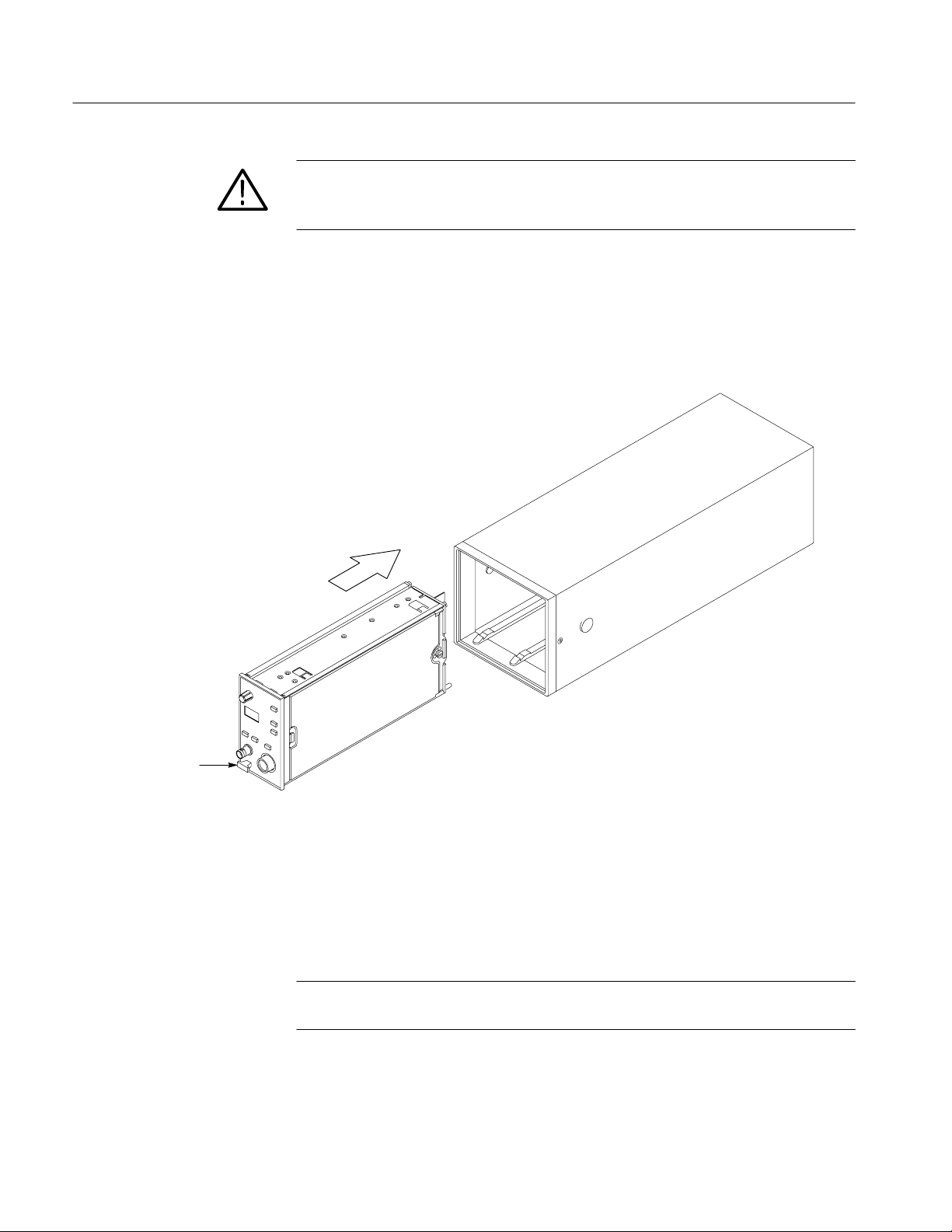
To install the Amplifier into the power module, align the grooves of the
Amplifier with the rails of the power module and push the Amplifier into the
power module until the instrument snaps into place (see Figure 1–4). To remove
the Amplifier, grasp the release lever at the lower left corner of the Amplifier
front panel and pull the Amplifier out of the power module.
Slide instrument into
power module
Release Lever
Figure 1–4: Installing the AM 503B and AM5030 into the Power Module
After you have installed the Amplifier and all other desired plug-in instruments
into the power module, you may turn the power module on. A digital readout
should appear on the Amplifier front panel and a coupling light should come on.
See Figure 2–4 on page 2–7 for the location of the coupling lights.
NOTE. When the AM 5030 is not connected to a GPIB controller, the SRQ light is
normally on.
1–6 AM 503B & AM 5030 Amplifier Instruction Manual

Connecting the Amplifier to an Oscilloscope
You will need an oscilloscope to display the AM 503B and AM 5030 measurement output. The oscilloscope must be capable of displaying a vertical scale
factor of 10 mV/div.
Use the supplied 50 BNC cable to connect the Amplifier OUTPUT connector
to your oscilloscope (see Figure 1–1 on page 1–2).
The input impedance of the oscilloscope channel must be 50 , otherwise you
will encounter slowed pulse response, increased aberrations, or incorrect DC
measurement amplitudes. If your oscilloscope provides only 1 M inputs, you
need to attach a 50 feed-through termination between the oscilloscope input
and the BNC cable. Do not install this termination at the Amplifier end of the
BNC cable.
To utilize the full bandwidth capability of the AM 503B and AM 5030 and
attached current probe, the oscilloscope bandwidth should be approximately five
times that of the current probe. For example, when using an A6312 Current
Probe, the oscilloscope bandwidth should be at least 500 MHz. When using an
A6302 Current Probe, the oscilloscope bandwidth should be at least 250 MHz.
Getting Started
After you have connected the Amplifier to the oscilloscope, make the following
adjustments to the oscilloscope channel you are using. Perform these adjustments only after all equipment has warmed up to a stable temperature; usually
20 minutes are required.
1. Make sure the oscilloscope input impedance is 50 . If your oscilloscope
provides only 1 M inputs, you need to attach a 50 feedthrough
termination between the oscilloscope input and the BNC cable. Do not
install this termination at the AM 503B and AM 5030 end of the BNC cable.
2. Set the vertical gain of the oscilloscope to 10 mV/div.
3. Set the oscilloscope ground reference so the trace appears at the center
graticule line or at the desired zero-current reference.
4. Set the input coupling of the oscilloscope to DC.
5. Turn off any oscilloscope bandwidth filters.
Once you have set up the oscilloscope, you do not need to further adjust the
oscilloscope vertical controls while you are using the AM 503B and AM 5030.
Use the oscilloscope controls to adjust the time base or trigger settings only.
NOTE. To maintain accurate readings while using the AM 503B and AM 5030,
the vertical gain of the oscilloscope channel must always remain at 10 mV/Div
and the coupling must remain at DC.
AM 503B & AM 5030 Amplifier Instruction Manual 1–7
Getting Started
Connecting a Current Probe to the Amplifier
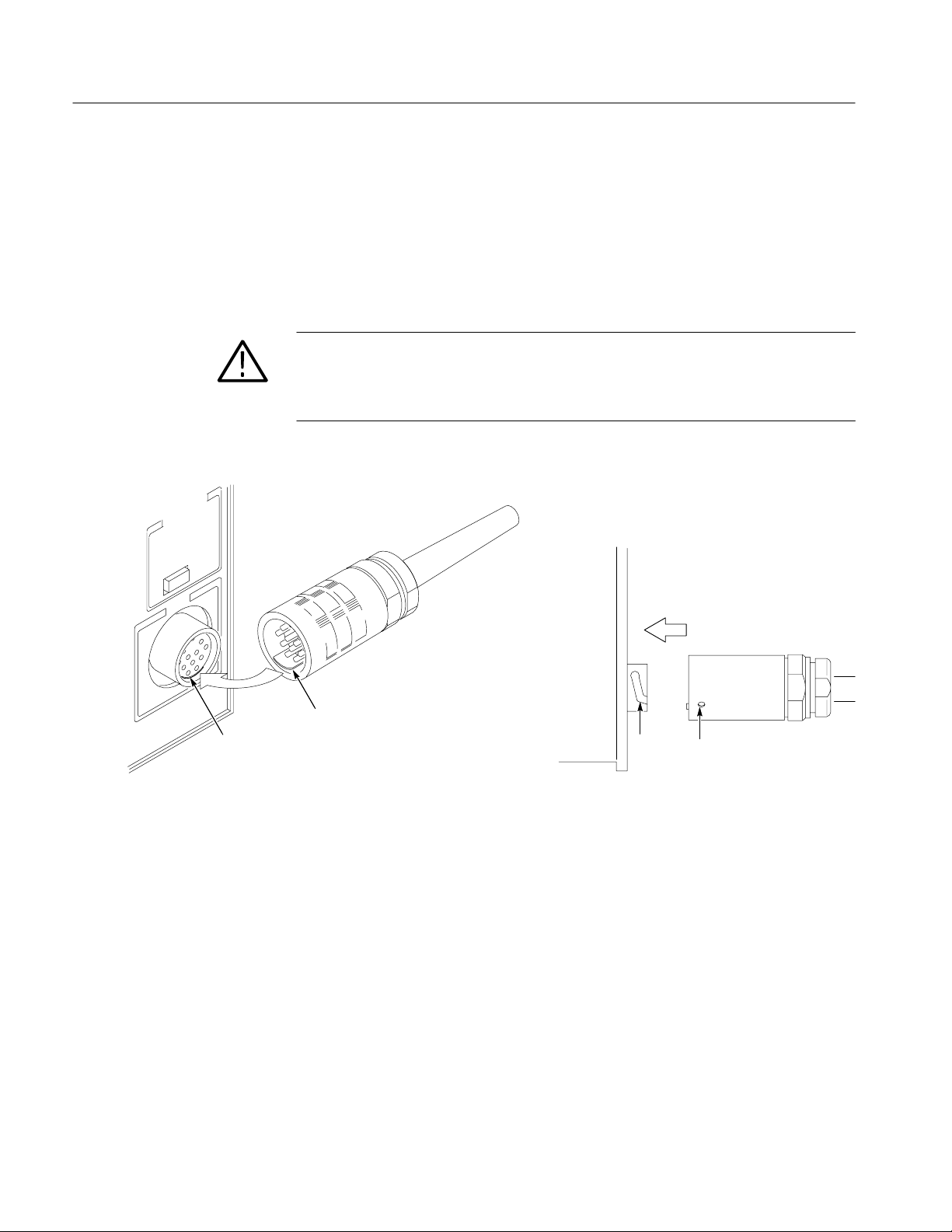
To connect a current probe to the Amplifier input connector, align the tab of the
probe connector with the slot in the Amplifier INPUT connector as shown in
Figure 1–5(a). Align the dot on the probe connector with the groove opening of
the input connector as shown in Figure 1–5(b). Push the probe connector in
while twisting the barrel clockwise to lock the connector.
CAUTION. Handle current probes with care. Do not drop a probe or subject it to
impact, or the core may crack. Do not connect or disconnect a current probe
while the probe is clamped around a live conductor, or while the AM 503B and
AM 5030 is powered on, or the probe may suffer electrical damage.
Amplifier
Current Probe Connector
Tab
Slot
(a) Align the Tab With the Connector Slot
Figure 1–5: Connecting a Current Probe to the Amplifier
Each current probe is calibrated before it is shipped, and should not require
further adjustment. If a probe requires adjustment, refer to the Adjustment
Procedure on page 6–1 or contact your nearest Tektronix Service Center. The
adjustment procedure should be performed only by qualified service personnel.
Push connector in
and twist to lock
Current Probe
Connector
Amplifier
(b) Insert the Connector Into the Amplifier
Groove
Alignment Dot
1–8 AM 503B & AM 5030 Amplifier Instruction Manual

Operating Basics

Measurements
This section provides operating techniques and measurement procedures for
using the AM 503B and AM 5030-compatible current probes.
Operating the Current Probe Slide
The current probes each have a slide mechanism that opens and closes the probe
jaw. This allows you to clamp the probe around a conductor under test. The slide
must be locked closed to accurately measure current or to degauss the probe. If a
probe is unlocked, the PROBE OPEN indicator on the Amplifier will light.
WARNING. When the probe slides are open, the exposed ferrite core pieces are
not insulated. To avoid injury or equipment damage, remove power from an
uninsulated wire before clamping the current probe around it.
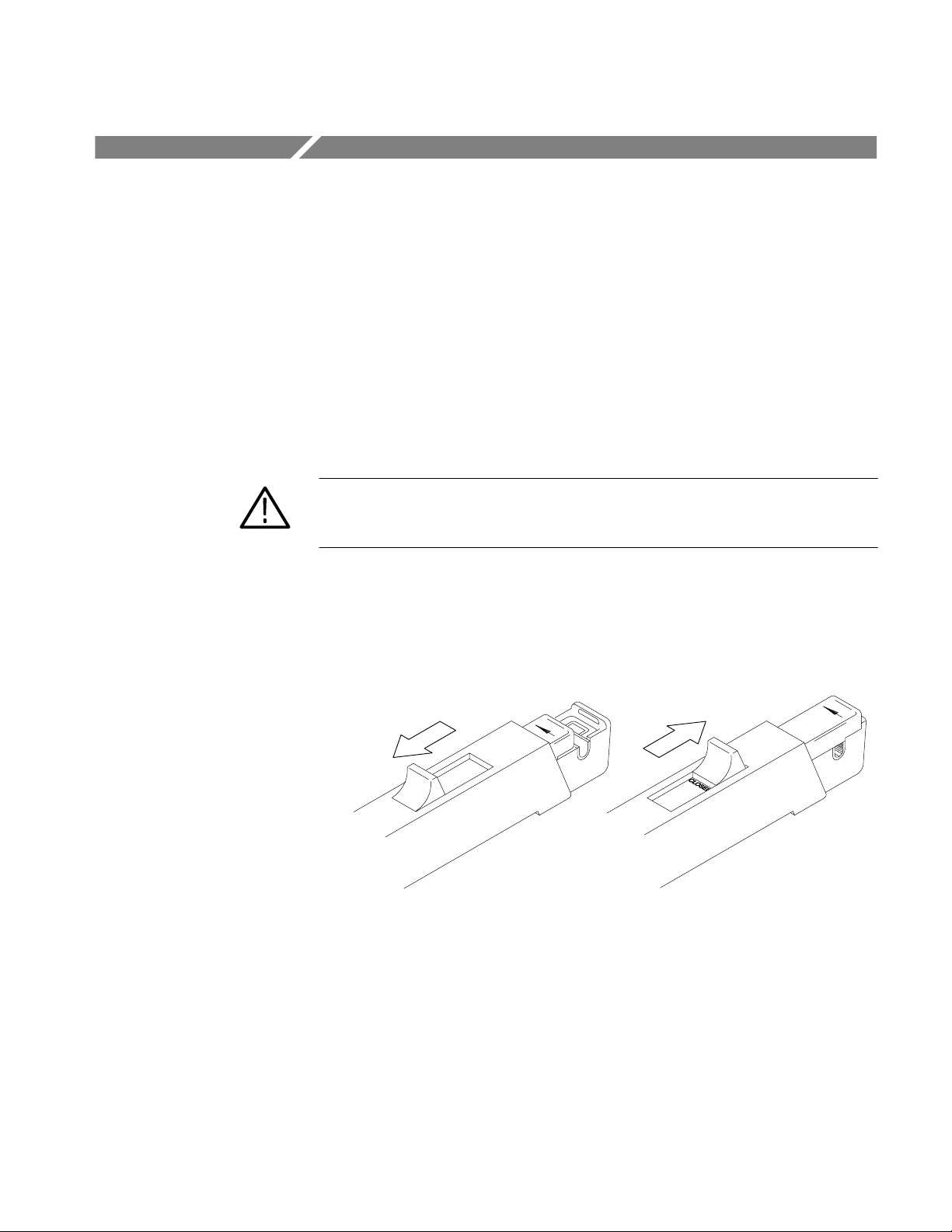
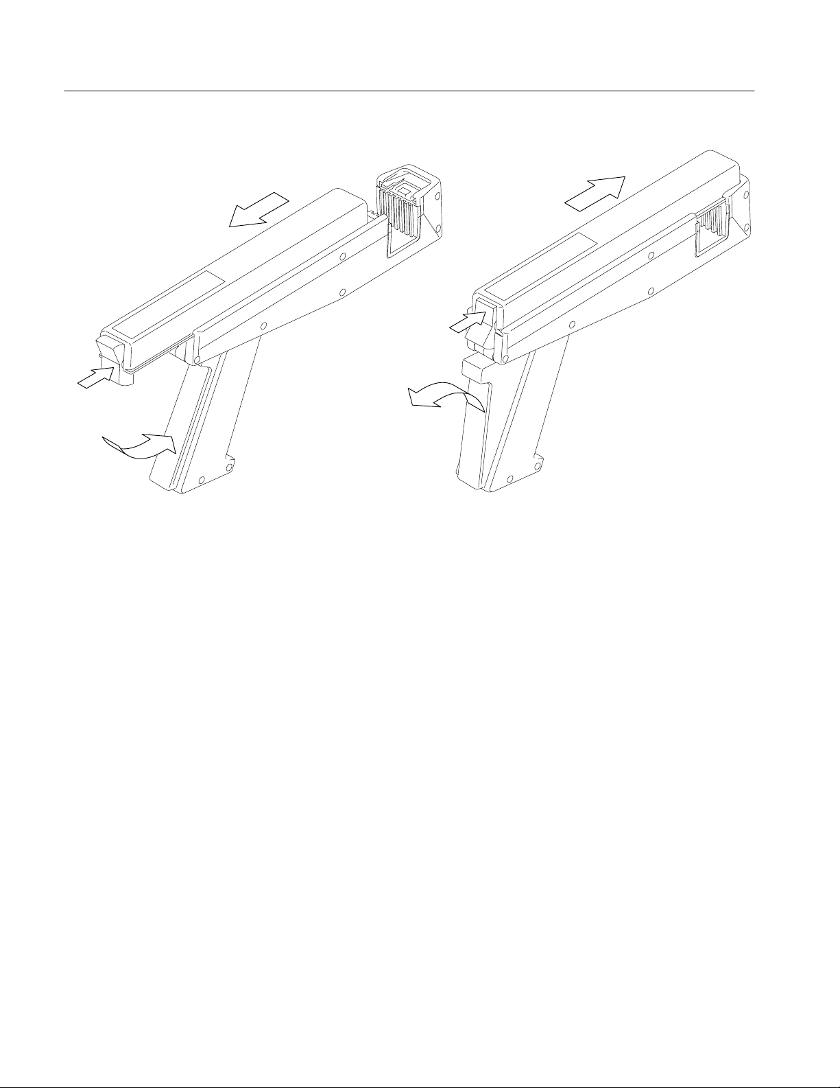
Figure 2–1 illustrates the slide operation of the A6312, A6302, and A6302XL
current probes. To open the probe, pull the slide back until the jaw is open. To
lock the probe, push the slide forward until the detent snaps into place.
Probe Open Probe Locked
Figure 2–1: A6312, A6302, and A6302XL Slide Operation
Figure 2–2 illustrates the slide operation of the A6303, A6303XL, and A6304XL
current probes. To open the probe, press the bottom of the lock button and
squeeze the handle until the core is open. To lock the probe, release the squeeze
handle and press the top of the lock button.
AM 503B & AM 5030 Amplifier Instruction Manual 2–1
Measurements
(1) Unlock the probe
(2) Squeeze
the handle
(a) Opening the Probe
(2) Lock the probe
(1) Release the handle
(b) Closing and Locking the Probe
Figure 2–2: A6303, A6303XL, and A6304XL Slide Operation
Degaussing and Autobalancing the Current Probe
Degaussing the probe removes any residual magnetization from the probe core.
Such residual magnetization can induce measurement error. Autobalancing
removes unwanted DC offsets in the amplifier circuitry.
Failure to degauss the probe is a leading cause of measurement errors. To
maintain measurement accuracy, degauss your probe in each of these cases:
H After turning on the Amplifier and allowing a 20-minute warm-up period.
H Before connecting the probe to a conductor or changing conductors under
test.
H Whenever an overload condition occurs.
H Whenever the probe is subjected to a strong external magnetic field.
H Periodically during normal use.
2–2 AM 503B & AM 5030 Amplifier Instruction Manual

Measurements
To degauss and autobalance a current probe, perform these steps:
1. Verify that the current probe is connected to the Amplifier.
2. Remove the current probe from the conductor under test.
3. Lock the probe slide closed (see Figures 2–1 and 2–2).
4. Press the Amplifier PROBE DEGAUSS AUTOBALANCE button.
NOTE. The degauss procedure will fail if the Amplifier is not properly connected
to an oscilloscope having 50 input impedance. If this occurs, an error code of
266 will be displayed on the Amplifier front panel.
After you have completed the oscilloscope adjustments and the Amplifier
degauss/autobalance procedure, your system is ready to measure current.
DC Measurements
To measure DC current, perform these steps:
1. Verify that the vertical gain of the oscilloscope is 10 mV/div, the input
coupling is DC, and the input impedance is set to 50 .
2. Adjust the ground reference of the oscilloscope to move the trace to the
desired graticule line.
NOTE. Once the first two steps have been completed, no further adjustments are
required on the oscilloscope vertical amplifier during the measurement session.
Use the Amplifier controls for everything except time base and trigger adjustment. See Figure 2–4.
3. Lock the probe closed without a conductor passing through it. Press the
Amplifier COUPLING button repeatedly until the REF light comes on, and
then press the Amplifier PROBE DEGAUSS AUTOBALANCE button.
4. After the degauss/autobalance routine completes, adjust the ground reference
(if necessary) using the Amplifier OUTPUT DC LEVEL control.
5. Open the probe slide, place the probe around the conductor under test, and
then lock the slide. For correct measurement polarity, make sure the probe
arrow is pointing in the direction of conventional (positive to negative)
current flow. Reversing the flow will display the current waveform upside-
down on the oscilloscope.
AM 503B & AM 5030 Amplifier Instruction Manual 2–3
Measurements
6. Press the Amplifier COUPLING button repeatedly until the DC light comes
on. Set the Amplifier CURRENT/DIVISION to the desired setting using
the
and buttons.
7. If necessary, vertically position the resulting waveform using the OUTPUT
DC LEVEL knob of the Amplifier.
8. Adjust the oscilloscope time base and trigger as needed.
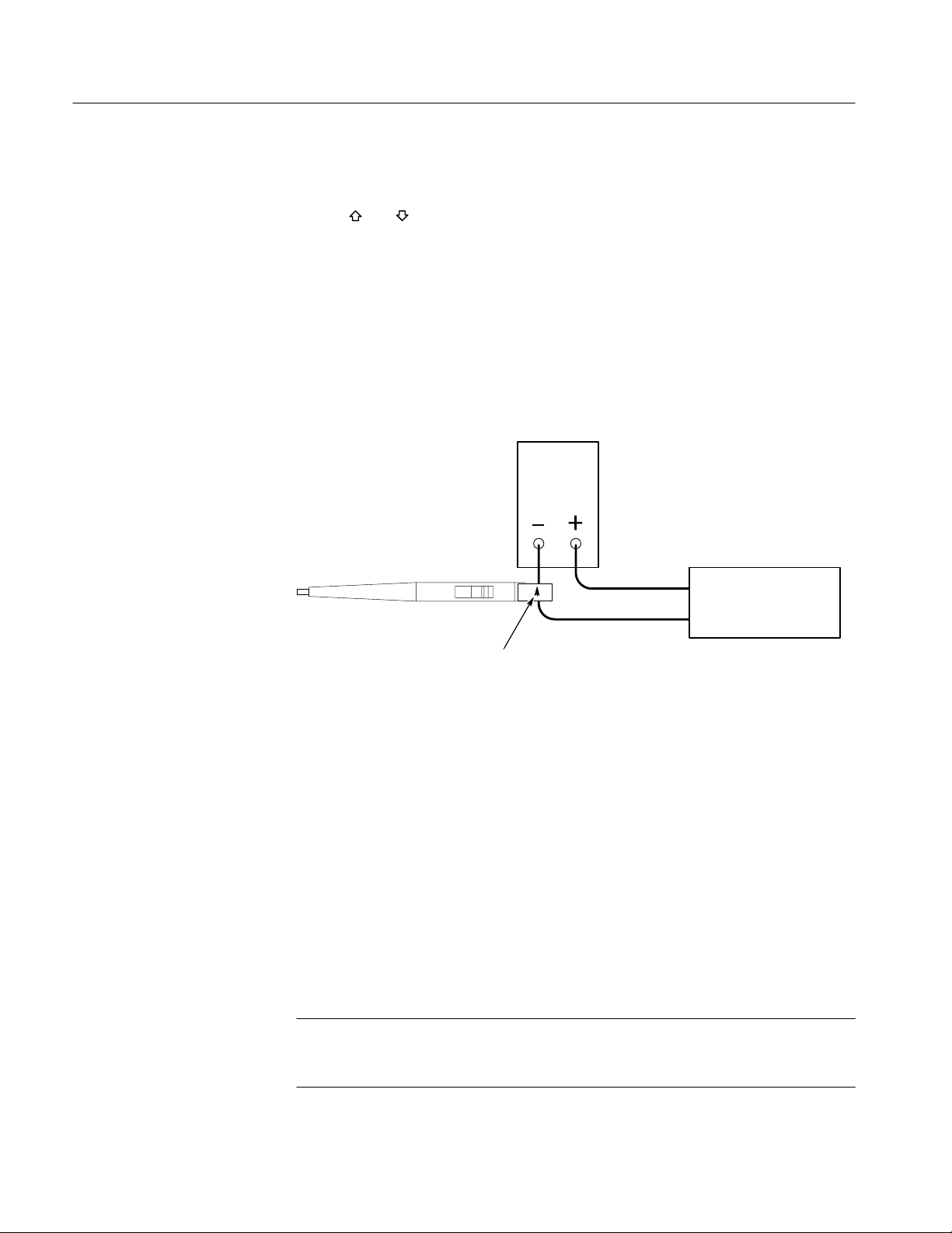
Figure 2–3 shows a current probe connected to a power supply line. Notice that
the probe arrow points toward the negative terminal of the power supply to
conform to the conventional current flow of positive (+) to negative (–).
Power Supply
AC Measurements
Current Probe
Load
Conventional Current Arrow
Figure 2–3: Current Probe Polarity
To measure AC current only, and remove the DC component of the current being
measured, follow the instructions below. These are identical to the instructions
for DC current measurements except that the Amplifier coupling in step 6 is set
to AC.
1. Verify that the vertical gain of the oscilloscope is 10 mV/div, the input
coupling is DC, and the input impedance is set to 50 .
2. Adjust the ground reference of the oscilloscope to move the trace to the
desired graticule line.
NOTE. Once the first two steps have been completed, no further adjustments are
required on the oscilloscope vertical amplifier during the measurement session.
Use the Amplifier controls for everything but time base and trigger adjustment.
2–4 AM 503B & AM 5030 Amplifier Instruction Manual

Measurements
3. Lock the probe closed without a conductor passing through it. Press the
Amplifier COUPLING button repeatedly until the REF light comes on, and
then press the Amplifier PROBE DEGAUSS AUTOBALANCE button.
4. After the degauss/autobalance routine completes, adjust the ground reference
(if necessary) using the Amplifier OUTPUT DC LEVEL control.
5. Open the probe slide, place the probe around the conductor under test, and
then lock the slide. For correct measurement polarity, make sure the probe
arrow is pointing in the direction of conventional (positive to negative)
current flow. Reversing the flow will invert the displayed current waveform
on the oscilloscope.
6. Press the Amplifier COUPLING button repeatedly until the AC light comes
on. Set the Amplifier CURRENT/DIVISION to the desired setting using
the
and buttons.
NOTE. Even when making AC current measurements, leave the oscilloscope
coupling on DC. Change only the Amplifier coupling to AC. Using the oscilloscope AC coupling may cause the Amplifier to exceed its output dynamic range.
7. If necessary, vertically position the resulting waveform using the OUTPUT
DC LEVEL knob of the Amplifier.
8. Adjust the oscilloscope time base and trigger as needed.
AM 503B & AM 5030 Amplifier Instruction Manual 2–5

Measurements
2–6 AM 503B & AM 5030 Amplifier Instruction Manual

Control Summary
This section describes the function of each AM 503B and AM 5030 front panel
control and connector. The overview in Figure 2–4 is followed by a detailed
description.
Some seldom-used functions do not appear in Figure 2–4. These functions are
completely discussed in the detailed descriptions that follow Figure 2–4.
The OUTPUT DC LEVEL knob
vertically positions the signal on the
oscilloscope screen.
The CURRENT/DIVISION display shows the
current AM 503B and AM 5030 scale factor in
either mA/division or A/division. Error codes
and output DC level also appear here.
The 20 MHz BW LIMIT button alternately
selects or deselects the 20 MHz bandwidth
limit for noise filtering.
Hold down the GPIB ADDRESS button while
adjusting the CURRENT/DIVISION buttons to
change the GPIB address. (AM 5030 only.)
The AM 503B and AM 5030 output appears at
the OUTPUT connector. Connect this to a 50
input of your oscilloscope.
Pull the release lever to remove the AM 503B and
AM 5030 from the power module.
Figure 2–4: The AM 503B and AM 5030 Front Panel
The two indicator lights: PROBE OPEN and
OVERLOAD give you local status information.
The two indicator lights: SRQ and REMOTE
give you remote status information. (AM 5030
only.)
The PROBE DEGAUSS AUTOBALANCE button
removes residual magnetism from the attached
current probe. The probe must be removed from
the test circuit and locked.
The CURRENT/DIVISION buttons change the
AM 503B and AM 5030 scale factor.
The COUPLING button selects AC or DC probe
coupling or a zero-current reference, as
indicated by the lights.
The current probes connect to the AM 503B and
AM 5030 at the INPUT connector.
AM 503B & AM 5030 Amplifier Instruction Manual 2–7

Control Summary
AM 503B and AM 5030 Controls
These front panel controls and indicators are common to both the AM 503B and
AM 5030 current probe amplifiers.
OUTPUT DC LEVEL
Control
PROBE OPEN Indicator
The OUTPUT DC LEVEL knob adjusts the DC offset that appears at the
Amplifier OUTPUT connector. The OUTPUT DC LEVEL knob adjusts the
displayed waveform relative to ground. After setting a zero-current reference, do
not use the oscilloscope vertical position to move the waveform up and down on
the display; use the Amplifier OUTPUT DC LEVEL knob instead.
As you adjust the OUTPUT DC LEVEL knob, the display shows you the output
level in divisions. When you stop moving the OUTPUT DC LEVEL knob, the
display reverts to show current per division.
The PROBE DEGAUSS AUTOBALANCE button will change the output DC
level setting if the Amplifier coupling is set to REF. In this case only, the output
DC level setting will be reset to ground; otherwise, the DC level setting will
remain at its previous setting.
NOTE. To maintain measurement accuracy, position the signal with the AM 503B
and AM 5030
!
When lit, this indicator informs you that the current probe is unlocked. You must
have the probe slide locked in order to degauss the probe or to accurately
measure current.
OVERLOAD Indicator
PROBE DEGAUSS
AUTOBALANCE Button
2–8 AM 503B & AM 5030 Amplifier Instruction Manual
When lit, this indicator informs you that the measurement you are taking exceeds
the continuous amplitude limit of the AM 503B and AM 5030. The detection
circuits only detect low frequency (≈10 kHz) and DC overloads. Since overloads
can magnetize the probe, you should always degauss the probe after an overload.
WARNING. To avoid personal injury or equipment damage, do not exceed the
specified electrical limits of the AM 503B and AM 5030 or any applicable
accessories.
When pressed, this button performs two functions that maximize measurement
accuracy. First, the Amplifier generates a degauss signal to remove any residual
magnetism from the attached current probe. Second, the Amplifier initiates an
operation to remove any undesired DC offsets from its circuitry. During the
degauss process, the Amplifier is busy and cannot be used to measure current.

Control Summary
The indicator light in the PROBE DEGAUSS AUTOBALANCE button will
blink whenever the Amplifier detects that the current probe needs degaussing or
DC balancing. The Amplifier cannot detect all circumstances that require probe
degaussing, so you may need to degauss the probe at times when the PROBE
DEGAUSS AUTOBALANCE light is not blinking. The blinking light serves as
a reminder to degauss the current probe when one of the following conditions
occurs:
H The Amplifier has just been turned on with a current probe connected.
H The current probe has been changed.
H The internal temperature of the Amplifier changed by more than 10° C.
H An overload has occurred.
The indicator stays on steady during the time the Amplifier is busy performing
the probe degauss functions. When the degauss and autobalance procedure is
complete, the indicator light turns off.
To perform the probe degauss/autobalance function, remove the probe from
around all conductors (or ensure that the conductor under test has no power),
make sure the probe is locked closed, and then press the PROBE DEGAUSS
AUTOBALANCE button.
The probe degauss/autobalance routine will not work if the current probe is
unlocked or disconnected from the Amplifier input. To properly degauss the
current probe, remove it from the conductor under test and lock the probe.
If the PROBE DEGAUSS AUTOBALANCE button is pressed while the
coupling is set to REF, the Output DC level is reset to ground. If either AC or
DC coupling is selected when the PROBE DEGAUSS AUTOBALANCE button
is pressed, the DC level is not changed from its previous setting.
NOTE. The Amplifier displays error code 266 when the Amplifier output is not
properly terminated into a 50 load. Make sure your Amplifier OUTPUT is
connected to an oscilloscope input using a 50 BNC cable, and that the
oscilloscope input is set to 50 impedance. See Figure 1–1 on page 1–2 for
proper cabling.
If your oscilloscope does not have 50 impedance settings for inputs, you can
place a 50 feed-through termination on the oscilloscope input and connect the
Amplifier output cable to the termination. Do not place the feed-through
termination at the Amplifier end of the BNC connecting cable.
AM 503B & AM 5030 Amplifier Instruction Manual 2–9

Control Summary
CURRENT/DIVISION
Buttons
COUPLING Button
The CURRENT/DIVISION
the AM 503B and AM 5030 in a 1–2–5 sequence. The setting of this control is
displayed on the digital readout and the units indicator. The CURRENT/DIVISION display indicates the Amplifier scale factor only; it is not a current
measurement readout. The measurement output is displayed on the oscilloscope.
NOTE. To maintain accurate measurements, the vertical gain of the oscilloscope
must remain at 10 mV/div.
The COUPLING button determines the coupling between the current probe and
the AM 503B and AM 5030. Press the COUPLING button repeatedly until the
desired indicator lights up. To couple the current probe for DC plus AC
measurements, use DC coupling. For AC measurements only, use AC coupling.
To establish a zero-current reference, use REF coupling. While using REF
coupling, you cannot measure current or view current waveforms.
NOTE. Even when making AC current measurements, leave the oscilloscope
coupling on DC. Change only the Amplifier coupling to AC. Using the oscilloscope AC coupling may cause the Amplifier to exceed its output dynamic range.
and buttons set the scale factor (sensitivity) of
20 MHz BW LIMIT Button
Probe Trim Adjust
The 20 MHz BW LIMIT button lets you limit the current probe amplifier
bandwidth to 20 MHz. This can be useful to remove high-frequency noise. Press
the button again to return to full bandwidth. When the button lights, the
bandwidth limit is on. System bandwidth depends on the type of current probe
you are using. Refer to the specifications table on page 4–3 for the bandwidth
limit frequency for your current probe.
After the PROBE DEGAUSS AUTOBALANCE routine has been run, the probe
and amplifier system will meet all published specifications; however, if you want
to improve the tolerance of the system accuracy, or to intentionally offset the
accuracy to make up for total system errors, the probe trim adjust routine may be
performed.
Probe trim adjust is a multiplicative factor that you can use to adjust the gain of
the current amplifier system. You can set this multiplier in increments of 0.001
from 0.750 through 1.250. Probe trim adjust is used for an optional calibration of
some current probes. If you are not performing such an adjustment, leave probe
trim adjust to the factory-default of unity gain (1.000).
To set probe trim adjust, press and hold the 20MHz BW LIMIT button while
pressing and releasing the COUPLING button. Use the
and buttons to
2–10 AM 503B & AM 5030 Amplifier Instruction Manual

Control Summary
adjust the setting that is displayed in the CURRENT/DIVISION display. When
finished, press either the 20MHz BW LIMIT or COUPLING button to restore
normal operation.
The display shows the last three significant digits of the display adjust setting;
the leading 0. or 1. are omitted. If the first digit displayed is 7, 8, or 9, then the
leading digit must be 0. If the first digit displayed is 0, 1, or 2, then the leading
digit must be 1.
OUTPUT Connector
INPUT Connector
The Amplifier current measurement output is accessed at the OUTPUT
connector, which should be connected to the oscilloscope input. Attach one end
of a 50 BNC cable to this connector and the other end to a 50 vertical input
of your oscilloscope. The output impedance of the Amplifier is 50 .
NOTE. To obtain accurate measurements, the input impedance of your oscilloscope must be 50 . Make sure your Amplifier OUTPUT is connected to an
oscilloscope input using a 50 BNC cable, and that the oscilloscope input is set
to 50 impedance. See Figure 1–1 on page 1–2 for proper cabling.
If your oscilloscope does not have 50 impedance settings for inputs, you can
place a 50 feedthrough termination on the oscilloscope input and connect the
Amplifier output cable to the termination. Do not place the feedthrough
termination at the Amplifier end of the BNC connecting cable.
All current probes compatible with the AM 503B and AM 5030 attach at the
INPUT connector, which is a 12-pin female connector. For information about
connecting a probe, see Connecting a Current Probe to the AM 503B and
AM 5030 on page 1–8.
CAUTION. To avoid equipment damage, turn the TM Series Power Module off
before removing or installing a current probe.
Release Lever
AM 503B & AM 5030 Amplifier Instruction Manual 2–11
The release lever has the Tektronix name printed on it. Pull the release lever to
remove the Amplifier from the power module.
CAUTION. To avoid equipment damage, turn the TM Series Power Module off
before removing or installing any plug-in unit.

Control Summary
AM 5030 GPIB Controls
These indicators and controls are unique to the AM 5030 and do not appear on
the AM 503B front panel.
SRQ Indicator
REMOTE Indicator
GPIB ADDRESS Indicator
GPIB ADDRESS Button
When lit, this indicator informs you that the AM 5030 has requested service
from the controller.
When lit, this indicator informs you that the front panel of the AM 5030 is
temporarily locked out because the Amplifier is responding to a GPIB command
from the controller.
The GPIB ADDRESS button has a light in it. When lit, this indicator informs
you that the AM 5030 has been addressed by the controller and that communication is taking place.
The GPIB ADDRESS button lets you set the AM 5030 device address. The
GPIB controller must use this address to send commands to the Amplifier. To set
the GPIB address, press and hold the GPIB ADDRESS button and, while
holding it down, use the
in the CURRENT/DIVISION display.
You can set the address from 0 (A00) through 30 (A30). You can also set the
Amplifier off line, which disables all communications with the controller. The
off line setting is A––.
and buttons to adjust the address that is displayed
GPIB Terminator
2–12 AM 503B & AM 5030 Amplifier Instruction Manual
The GPIB ADDRESS and 20MHz BW LIMIT buttons together let you define
the AM 5030 GPIB terminator. The terminator may be set to EOI only or EOI
followed by LF. To set the GPIB terminator, press and hold the GPIB ADDRESS button, and also press and hold the 20 MHz BW LIMIT button. While
holding them down, use the
displayed in the CURRENT/DIVISION display. The display shows EOI if the
terminator is EOI only and LF if the terminator is EOI followed by LF.
and buttons to adjust the setting that is
GPIB Operation
NOTE. This material applies only to the AM 5030 Programmable Amplifier. The
AM 503B does not support a GPIB interface.
You can use a computer to control the AM 5030 and make measurements. With
an oscilloscope that also can be programmed, the computer and AM 5030 can
form a complete, automated measurement system.
Your computer, also known as the controller, must be capable of operating on a
GPIB bus that conforms to IEEE Std 488.1–1987. GPIB cards are available to
provide this capability for personal computers.
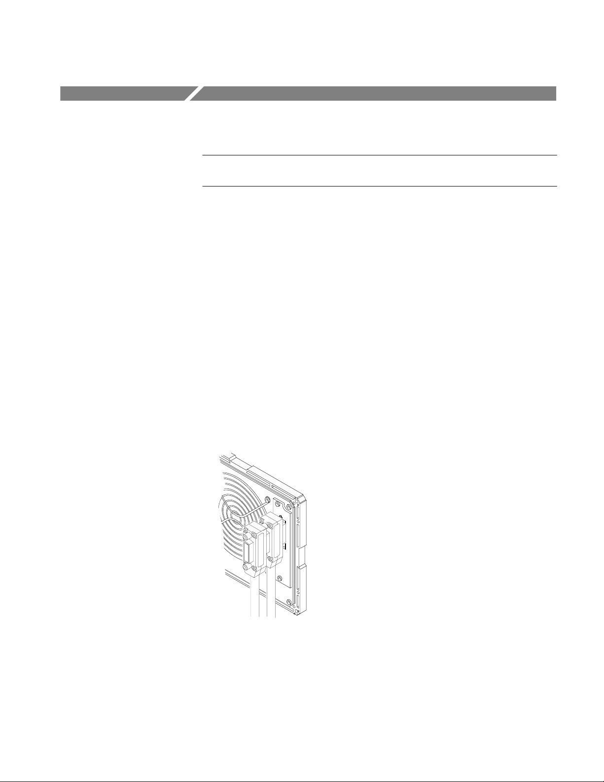
The TM 5000 Series Power Module has a 24-pin GPIB connector on its rear
panel, as shown in Figure 2–5. This connector has a D-type shell and conforms
to IEEE Std 488.1–1987.
Attach an IEEE Std 488.1–1987 GPIB cable (see Optional Accessories in the
Replaceable Mechanical Parts section) between this connector and your
controller. Figure 2–5 also shows how cables can be stacked together. You can
stack a second cable on either the TM 5000 Series Power Module connector or
the controller connector, to similarly connect your oscilloscope.
Figure 2–5: Stacked GPIB Connectors
AM 503B & AM 5030 Amplifier Instruction Manual 2–13
GPIB Operation
GPIB Requirements
Observe these rules when you use your AM 5030 with a GPIB network:
H Assign a unique device address to each device on the bus. No two devices
can share the same device address.
H Do not connect more than 15 devices to the bus.
H Connect one device for every 2 meters (6 feet) of cable used.
H Do not use more than 20 meters (65 feet) of cable for the entire bus.
H Turn on at least two-thirds of the devices on the network while using the
network.
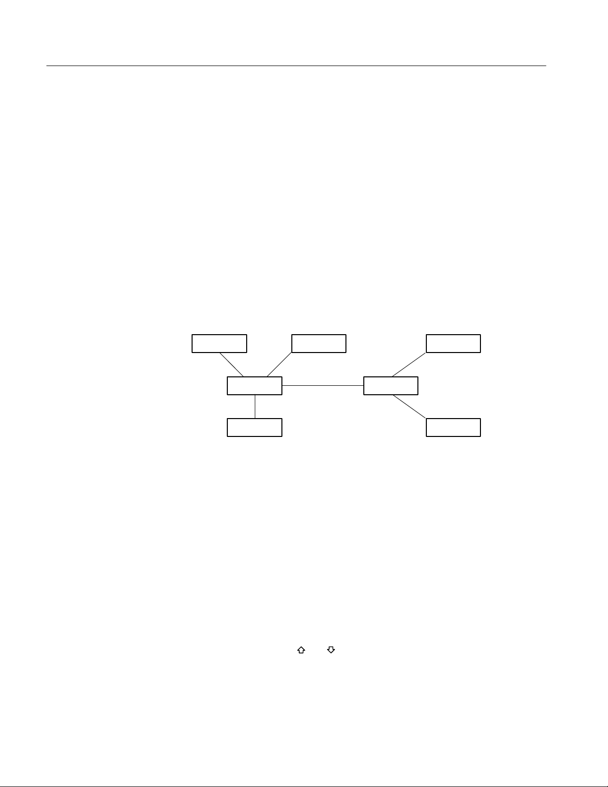
H Connect the devices on the network in a star or linear configuration as shown
in Figure 2–6. Do not use loop or parallel configurations.
GPIB Device
Figure 2–6: T ypical GPIB Network Configurations
Setting the GPIB Parameters
You must set the GPIB parameters of the AM 5030 to match the configuration of
the bus and controller.
GPIB Address
The GPIB ADDRESS button lets you set the AM 5030 device address. The
GPIB controller must use this address to send commands to the AM 5030. The
address of the AM 5030 must be different from the addresses used by all other
devices on the bus.
GPIB Device
GPIB Device
GPIB Device
GPIB Device
GPIB Device
GPIB Device
To set the GPIB address, press and hold the GPIB ADDRESS button and, while
holding it down, use the
and buttons to adjust the address that is displayed
in the digits. You can set the address from 0 (A00) through 30 (A30). You can
also set the AM 5030 off line, which disables all communications with the
controller. The off line setting is A––.
2–14 AM 503B & AM 5030 Amplifier Instruction Manual

GPIB Operation
GPIB Terminator
Pressing both the GPIB ADDRESS and 20MHz BW LIMIT buttons at the same
time lets you set the AM 5030 GPIB terminator. The terminator may be set to
EOI only or EOI followed by LF. You will need to consult your controller
documentation to determine which setting is best for your configuration.
To set the GPIB terminator, press and hold both the GPIB ADDRESS and
20MHz BW LIMIT buttons and, while holding them down, use the
buttons to adjust the setting that is displayed in the digits. The display shows
EOI when the terminator is EOI only and LF when the terminator is EOI
followed by LF.
Other Documents You Will Need
We cannot know what type of controller you will use with your AM 5030. This
document cannot cover the topics that are specific to your installation. To
completely understand and implement a GPIB system, you will need the
documentation that supports your controller. If you are using a personal
computer with a GPIB card, you will need the documentation for both the PC
and the GPIB card.
and
AM 503B & AM 5030 Amplifier Instruction Manual 2–15

GPIB Operation
2–16 AM 503B & AM 5030 Amplifier Instruction Manual
Functional Command Groups
NOTE. This material applies only to the AM 5030 Programmable Amplifier. The
AM 503B does not support a GPIB interface.
The AM 5030 GPIB interface commands fall into four groups:
H Front panel commands
H GPIB Status commands
H Amplifier Status commands
H Probe Status commands
Command names show both upper- and lower-case characters. Only the
upper-case characters are required. You can abbreviate commands by omitting
lower-case characters, starting from the end. For example, you can enter the
ALLEve command as ALLEVE, ALLEV, or ALLE.
The AM 5030 is not case-sensitive. You can use lower-case letters anyplace in
command names or arguments: alLeVe, AllEv, or alle are valid.
Front Panel Commands
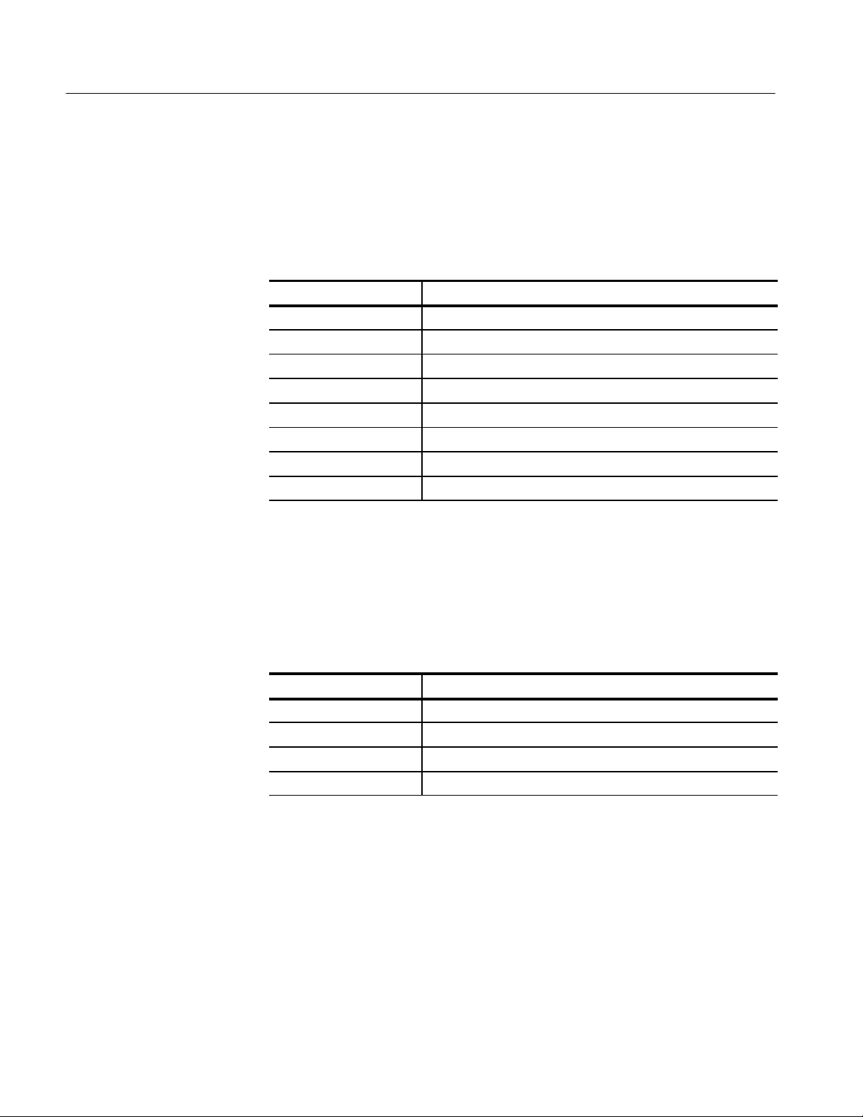
The commands listed in Table 2–1 are used to control or duplicate the front panel
controls and indicators of the AM 5030.
T able 2–1: Front Panel Commands
Command Name Description
AMPS Sets output resolution
BWLIMit Sets or resets bandwidth limiting
COUpling Sets input coupling
DCLEVel Adjusts output DC offset (reference) level
DEGAuss Starts the degauss/autobalance sequence
FPLock Disables and enables front-panel controls
OVerload? Returns the state of the overload indicator
UNIts? Returns units of AM 5030 output
AM 503B & AM 5030 Amplifier Instruction Manual 2–17
Functional Command Groups
GPIB Status Commands
The commands listed in Table 2–2 are used to provide event information and
configure the GPIB interface.
T able 2–2: GPIB Status Commands
Command Name Description
ALLEve? Returns all pending event codes
ERRor? Returns the last pending event code
EVent? Returns the last pending event code
EXit Recovers from an error condition
HELp? Returns a list of AM 5030 GPIB commands
PATH Sets whether queries return command names
RQS Enables or disables system requests (SRQs)
SET? Returns all AM 5030 settings as command string
Amplifier Status Commands
The commands listed in Table 2–3 are used to identify, configure, and test the
AM 5030 amplifier.
T able 2–3: Amplifier Status Commands
Command Name Description
ID? Returns instrument ID including firmware version numbers
INIT Initializes AM 5030 to factory default settings
SERIAL? Returns AM 5030 serial number
TEST Performs AM 5030 self test
2–18 AM 503B & AM 5030 Amplifier Instruction Manual

Probe Status Commands
The commands listed in Table 2–4 are used to adjust and provide information
about the probe currently in use.
T able 2–4: Probe Status Commands
Command Name Description
PROBEOPen? Returns the state of the probe open indicator
PROBETRim Sets probe gain adjustment factor
PROBETY pe? Returns model of current probe being used
NOTE. The PROBETYpe? query returns PROBETYPE A6302 for both A6302 and
A6312 current probes.
Functional Command Groups
AM 503B & AM 5030 Amplifier Instruction Manual 2–19

Functional Command Groups
2–20 AM 503B & AM 5030 Amplifier Instruction Manual

Commands
ALLEve? (Query Only)
This section supports the GPIB commands with command definitions, syntax,
return messages, and examples.
Returns a comma-delimited list of up to 41 pending event codes. If no event is
pending, it returns the code for “no events to report.”
AMPS
Syntax
Returns
Examples
Syntax
ALLEve? only produces meaningful results when RQS is off. When RQS is on,
ALLEve? operates the same as EVent?, except that the returned header is
ALLEVE instead of EVENT.
ALLE?
might return 266, indicating that the degauss/autobalance routine has failed
because the AM 5030 OUTPUT is not terminated into 50 .
Sets or queries the resolution of the AM 5030.
Arguments
Examples
AM 503B & AM 5030 Amplifier Instruction Manual
<Number> is in amperes per division, and should represent a valid setting for the
probe being used. Numbers will be rounded to the nearest setting in a 1–2–5
sequence.
AMPS 0.005
sets the resolution of the AM 5030 to 5 mA/division.
AMPS?
might return AMPS 5E–3, indicating that the AM 5030 resolution of the
AM 5030 is 5 mA/division.
2–21

Commands
BWLIMit
Sets or queries the 20 MHz bandwidth limit switch.
COUpling
Syntax
Arguments
Examples
Syntax
ON turns bandwidth limiting on; OFF turns bandwidth limiting off.
BWLIM ON
turns on bandwidth limiting.
BWLIM?
might return BWLIMIT OFF, indicating that bandwidth limiting is off.
Sets or queries the input coupling of the AM 5030.
2–22
Arguments
Examples
AC sets the input to AC coupling. DC sets the input to DC coupling. REF sets
the input to ground reference.
COU DC
sets the AM 5030 input to DC coupling.
COU?
might return COUPLING REF, indicating that the AM 5030 input is set to
ground reference.
AM 503B & AM 5030 Amplifier Instruction Manual

DCLEVel
Commands
Sets the DC offset level of the AM 5030. This is the current level that will be
displayed at the oscilloscope ground reference level. This programming
command is the most accurate means to set the DC offset level; the front panel
OUTPUT DC LEVEL control is less precise.
Syntax
Arguments
Examples
<Number> specifies the offset in amperes. The value may range ±10 times the
sensitivity (AMPS) setting. For example, if the current AMPS setting is 1 A/div,
the valid range of the DCLEVel is from –10 A to 10 A.
DCLEV 0.1
sets the DC offset level to 0.1 A.
DCLEV?
might return 1, indicating that the DC offset level is currently 1 A.
DEGAuss (No Query Form)
Initializes the probe degauss/autobalance sequence.
Syntax
Arguments
Examples
AM 503B & AM 5030 Amplifier Instruction Manual
If the argument is omitted or is zero, the command operates like the front panel
PROBE DEGAUSS AUTOBALANCE button; it recalibrates gain only if a
significant temperature change has occurred since the last calibration.
An argument of 1 forces a gain calibration, even if it would normally be
bypassed because of insufficient temperature change since the last calibration.
An argument of 2 performs a gain calibration only, without balancing the Hall
device. This is used when adjusting the A6302 and A6302XL current probe DC
offset adjustment. See page 6–4.
DEGA
operates just like pressing the PROBE DEGAUSS AUTOBALANCE button.
2–23

Commands
ERRor? (Query Only)
Returns the error or event code for the most recent event reported by serial poll,
or for the highest priority condition pending.
ERRor? and EVent? function identically.
Syntax
Returns
Examples
EVent? (Query Only)
Syntax
Returns
Examples
The most recent error/event code.
ERR?
might return 266 as the most recent error code.
Returns the error or event code for the most recent event reported by serial poll,
or for the highest priority condition pending.
EVent? and ERRor? function identically.
The most recent error/event code.
EV?
might return 266 as the most recent error code.
EXit
2–24
Syntax
Causes the AM 5030 to exit a test mode or recover from an error condition.
AM 503B & AM 5030 Amplifier Instruction Manual

FPLock
Commands
Enables and disables the front panel buttons. When locked, the AM 5030 front
panel buttons and knob are completely inoperative.
Syntax
Arguments
Examples
HELp? (Query Only)
Syntax
ON turns on the front panel lock, which disables buttons and knob. OFF restores
operation of the buttons and knob.
FPL OFF
restores the operation of the front panel buttons and knob.
FPL?
might return ON, indicating that the front panel buttons and knob are inoperative
because they are locked.
Returns a list of commands that are recognized by the AM 5030.
Returns
AM 503B & AM 5030 Amplifier Instruction Manual
Will always return the string HELP ALLEVE, AMPS, BWLIMIT, COUPLING,
DCLEVEL, DEGAUSS, ERROR, EVENT, EXIT, FPLOCK, HELP, ID, INIT,
OVERLOAD, PATH, PROBEOPEN, PROBETRIM, PROBETYPE, RQS,
SERIAL, SET, TEST, UNITS
2–25

Commands
ID? (Query Only)
Returns the AM 5030 identification, including the name, Codes & Formats
version, main board firmware version, and GPIB board firmware version.
Syntax
Returns
Examples
INIT (No Query Form)
The instrument identification string.
ID?
may return the string ID TEK/AM 5030, V81.1, MAIN/1.0, GPIB/1.0.
Initializes the AM 5030 to factory default settings.
H COUPLING is set to GROUND
H Amps/division is set to minimum for attached probe
H BW LIMIT is set to OFF.
H DC LEVEL is set to 0 (zero)
H The degauss lamp will flash (if probe is connected) indicating that a probe
degauss is required
Syntax
OVerload? (Query Only)
Syntax
Returns
Examples
2–26
PROBETRim settings are not changed.
Returns the status of the overload indicator (the front panel OVERLOAD light).
OV?
might return OVERLOAD ON, indicating an overload condition has occurred.
AM 503B & AM 5030 Amplifier Instruction Manual

PATH
Commands
Controls whether queries return the command header (the command name) along
with the returned data. With PATH off, BWLIMIT? might return ON. With
PATH on, the same query would return BWLIMIT ON.
The PATH command does not affect the data returned from SET?, which will
always return command headers. This is because the reply to SET? must always
be able to be sent as a command string to the AM 5030.
Syntax
Arguments
Examples
ON turns header return on. OFF prevents the inclusion of command name
headers in query return strings other than SET?.
PATH OFF
eliminates headers (command names) from query return strings.
PATH?
might return OFF to indicate that headers are removed from query return strings,
or PATH ON to indicate that headers are included in query return strings.
PROBEOPen? (Query Only)
Returns the status of the probe open indicator (the front panel PROBE OPEN
light).
Syntax
Returns
Examples
AM 503B & AM 5030 Amplifier Instruction Manual
PROBEOP?
might return PROBEOPEN ON, indicating that the probe is not locked shut.
2–27

Commands
PROBETRim
Lets you specify a multiplicative gain factor (trim adjustment) for probe
compensation. There is a trim adjustment value for each type of probe (for
example, A6302/A6312, A6302XL, A6303, A6303XL, or A6304XL). This
command will set or query only the trim adjustment for the type of current probe
currently connected to the AM 5030. If no probe is connected, executing this
command or query will cause error 264, “No probe connected.”
Probe trim is used to perform an optional fine-tune calibration of the A6303
Current Probe
NOTE. The AM 5030 amplifier retains only one trim adjustment value for each
probe type. Before using another probe of the same type, you must specify a new
gain factor. The AM 5030 amplifier regards the A6302 and A6312 as the same
probe type.
Syntax
Arguments
Examples
<number> is a multiplicative gain factor, in the range 0.750 to 1.250 in
increments of 0.001. The probe input will be multiplied by this gain factor.
PROBETR 1
sets the trim adjustment to unity for the type of probe currently connected to the
AM 5030.
PROBETR?
might return PROBETRIM 1.1, indicating that the probe trim adjustment is
currently set to 1.1 for probes of the type of probe currently connected to the
AM 5030.
2–28
AM 503B & AM 5030 Amplifier Instruction Manual

PROBETYpe? (Query Only)
Returns the type (model) of current probe connected to the AM 5030 INPUT
connector. The return string NOPROBE indicates that no current probe is
connected.
Commands
RQS
Syntax
Returns
Examples
PROBETYpe?
PROBETYPE A6302
PROBETYPE A6303
PROBETYPE A6302XL
PROBETYPE A6303XL
PROBETYPE A6304XL
PROBETYPE NOPROBE
PROBETY?
might return PROBETYPE A6303, indicating that a A6303 Current Probe is
attached to the INPUT connector of the AM 5030.
NOTE. The PROBETY? query returns PROBETYPE A6302 for both A6302 and
A6312 current probes.
Enables or disables SRQs (System Requests). When disabled, the AM 5030 does
not act on error conditions other than to log them, and does not signal that it is
ready to transmit data to the controller.
Syntax
Arguments
Examples
AM 503B & AM 5030 Amplifier Instruction Manual
RQS ON
RQS OFF
RQS?
ON enables SRQ events. Off disables SRQ events.
RQS ON
enables SRQ events.
2–29

Commands
SERIAL? (Query Only)
Returns the serial number of the AM 5030.
Syntax
Returns
Examples
SET? (Query Only)
Syntax
The instrument serial number as an ASCII string. The serial number is an eight
digit string, always starting with a space (ASCII 32) character.
SERIAL?
might return SERIAL B018607.
Returns a string containing all the individual programming commands required
to return the AM 5030 to its present state. This string can be saved and sent at
some future time when you want to return the AM 5030 to all the present
settings.
Because this string is intended to be sent back to the AM 5030, the return string
contains command headers (names) regardless of the setting of the PATH
command.
2–30
Returns
Examples
! " " "
! " "
! "
SET?
might return AMPS 1.0; BWLIMIT OFF; COUPLING DC; DCLEVEL 0.5;
FPLOCK OFF; PATH ON; PROBETRIM 1.000; RQS ON;.
AM 503B & AM 5030 Amplifier Instruction Manual

TEST (No Query Form)
Commands
Instructs the AM 5030 to perform a self-test operation and return the error code
of the first error that occurs. If no error occurs, TEST will return 0.
Syntax
Returns
Examples
UNIts? (Query Only)
Syntax
TEST
might return TEST 0, indicating that the self-test completed successfully with no
errors.
TEST
might return TEST 357; low battery.
Returns the output units of the AM 5030. Normally, these will be amperes
whenever a current probe is connected to the AM 5030 OUTPUT. Whenever a
voltage adapter or loop-through adapter is connected (both are calibration
fixtures), the units will be volts.
Returns
Examples
AM 503B & AM 5030 Amplifier Instruction Manual
UNI?
might return A, indicating that a current probe is connected to the AM 5030
OUTPUT connector, and the output units are amperes.
2–31

Commands
2–32
AM 503B & AM 5030 Amplifier Instruction Manual

Error Messages & Codes
NOTE. This material applies primarily to the AM 5030 Programmable Amplifier.
Event Codes displayed on the front panel apply also to the AM 503B.
These are the event codes (also known as error codes) that the AM 5030 can
generate, along with their meaning. Some of these codes may also appear on the
front panel in the CURRENT/DIVISION readout.
T able 2–5: AM 5030 Event Codes
Displayed on
Error Number
0 No Null event. Reported when RQS is ON and EVent?, ERRor?, or ALLEve? is attempted prior to
101 No Invalid GPIB command.
154 No Invalid number in GPIB command.
155 No Invalid quoted string. String may be more than 128 characters, be terminated with EOI (or LF if
156 No Invalid GPIB command.
157 No Syntax error .
160 No Expression too complex.
203 No I/O buffers full, so output buffer was dumped. This may happen if you send a sequence of
250–251 No Invalid GPIB command.
252 No AMPS argument out of range. Command not executed.
253 No DCLEVel argument out of range. Command not executed.
254–256 No Invalid GPIB command.
257 No PROBETRim argument out of range. Command not executed.
258–260 No Invalid GPIB command.
261 No DEGAuss argument out of range. Command not executed.
262 No Invalid GPIB command.
263 Yes Probe opened during degauss/autobalance.
264 No No probe attached to INPUT connector . This can also occur if a current probe is defective.
265 No Probe open when degauss/autobalance initiated.
266 Yes The Amplifier OUTPUT was not terminated into 50. It can also be caused by faulty hardware.
267 Yes Internal buffer overflow .
268 No Invalid GPIB command.
Front Panel
Description of Error
reading the serial poll status byte.
terminator is set to EOI and LF), or contain an ASCII NUL (0).
queries without talk-addressing the AM 5030.
AM 503B & AM 5030 Amplifier Instruction Manual
2–33

Error Messages & Codes
T able 2–5: AM 5030 Event Codes (Cont.)
Displayed on
Error Number Description of Error
350 Yes Amplifier needs repair. Cannot EXit from this error.
351–354 Yes Amplifier needs repair.
355 Yes NVRAM failure, Amplifier reset to factory default. Will occur first power up after new firmware
356 Yes Amplifier needs repair .
357 Yes
358 Yes An error occurred while the AM5030 was restoring previously-saved settings.
359 Yes Probe needs repair; AM5030 cannot recognize the probe type.
360–362 Yes Amplifier needs repair.
363–364 Yes Amplifier or probe needs repair.
400 No AM5030 function normal, no events to report.
401 No Power on has occurred.
450 No Degauss/autobalance complete.
550–594 Yes Error occurred during internal automatic adjustment. Repeated errors in the range 550–594
650 No Timer indicates too long since last degauss; probe should be degaussed. PROBE DEGAUSS
651 No Probe overload occurred; probe should be degaussed. PROBE DEGAUSS AUTOBALANCE
652–653 No The automatic Hall-device biasing circuit is at the end of its compensation range; probe should
Front Panel
has been installed.
Internal battery is weak and needs replacement.
(displayed as L0)
indicate the Amplifier needs repair. 580 and 581 indicate that the Amplifier was unable to
complete a probe offset adjustment. See the DC Offset Adjustment procedure for the particular
probe you are using.
AUTOBALANCE light will blink until probe degaussed.
light will blink until probe degaussed.
be degaussed. PROBE DEGAUSS AUTOBALANCE light will blink until probe degaussed.
2–34
AM 503B & AM 5030 Amplifier Instruction Manual

Reference

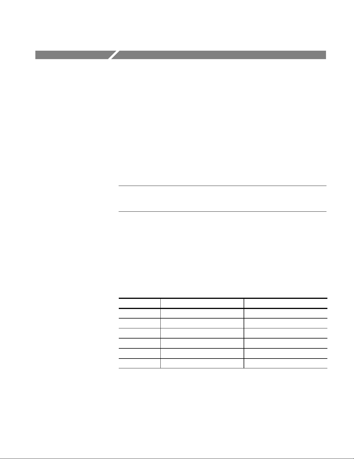
Reference Notes
These notes are provided to help you realize the full potential of the AM 503B
and AM 5030 current probe systems.
Degaussing a Probe with an Unpowered Conductor in the Jaws
Under almost all conditions, you can degauss your current probe while a
conductor of an unpowered circuit is clamped in the jaws. The advantage of
degaussing with an unpowered circuit is that any offset from stray DC magnetic
fields are compensated. In an automated environment, degaussing with the
conductor in the probe jaws eliminates the need to manually remove the probe.
NOTE. Be certain that the conductor in the probe jaws is completely unpowered.
Any current flowing through the conductor will cause a residual offset in the
current probe, and the Amplifier may fail calibration.
If the impedance of your circuit is higher than that shown in Table 3–1, the
degauss procedure will succeed because the Amplifier will be able to saturate the
probe core. While degauss occurs, the probe will induce a voltage in the
unpowered circuit. This also appears in Table 3–1. Your circuit must be able to
absorb this induced voltage. With low impedance circuits, several amperes may
be induced in the circuit being measured. This may be of concern when you are
using very small conductors.
T able 3–1: Unpowered Circuit Degauss Limits
Probe Type Minimum Circuit Resistance Maximum Induced Voltage
A6312 10m 40 mV at 200 Hz
A6302 10m 40 mV at 200 Hz
A6303 5m 30mV at 200 Hz
A6302XL 10 m 40 mV at 200 Hz
A6303XL 5m 30 mV at 200 Hz
A6304XL 1m 15 mV at 100 Hz
AM 503B & AM 5030 Amplifier Instruction Manual 3–1

Reference Notes
Bandwidth Limiting
You can reduce the apparent noise on a current waveform by pressing the 20MHz
BW LIMIT button on the AM 503B and AM 5030. You can also use the
bandwidth limiting of your oscilloscope.
WARNING. Do not exceed the specified bandwidth limits of your current probe.
Measuring frequencies in excess of the specified limit can cause the probe to
overheat severely, resulting in personal injury or damage to the equipment. Refer
to the probe Instructions for frequency derating.
Measuring Differential Current
You can place two conductors in a current probe to provide differential or null
current measurement. This avoids the necessity of using two current measurement systems with a differential oscilloscope amplifier.
1. Orient the two conductors under test so that the polarities oppose each other.
Clamp the current probe around the two conductors as shown in Figure 3–1.
2. Measure the current. A waveform above the baseline indicates the conductor
with the conventional current flow in the direction of the probe arrow is
carrying the greater current. Conventional current flows from positive to
negative.
3. To adjust for a current null, adjust the current in one of the conductors until
the displayed measurement is zero.
Conductor #2
Conductor #1
Current
Current
Current Probe
Figure 3–1: Measuring Differential Current and Nulls
3–2 AM 503B & AM 5030 Amplifier Instruction Manual

AC and DC Coupling
Reference Notes
You can couple the signal input to the AM 503B and AM 5030 with either DC or
AC coupling. DC coupling shows the DC and AC measurement components
while AC coupling removes the DC component from the displayed signal. When
you use AC coupling, make sure that the input DC current does not exceed the
probe specifications.
AC coupling will affect waveforms at frequencies higher than the AC Coupling
Low-Frequency Bandwidth. For example, pulsed currents may exhibit rolloff or
decreased amplitude. Figure 3–2(a) shows a low-frequency square wave using
AC coupling. The signal exhibits low-frequency rolloff. By changing the
Amplifier coupling to DC, the pulse is displayed as truly square, as shown in
Figure 3–2(b).
(a) AC-Coupled Signal
Figure 3–2: Effect of AC or DC Coupling on Low-Frequency Signals
If you are trying to examine a low-frequency signal that is superimposed on a
comparatively large DC component, you can resolve the signal by performing
these steps:
1. Press the COUPLING button on the Amplifier repeatedly until the AC light
goes on.
2. Adjust the CURRENT/DIVISION controls on the Amplifier so that the
signal shows maximum detail without going off the oscilloscope screen.
3. Press the COUPLING button of the Amplifier repeatedly until the DC light
goes on. Center the DC component on the zero-current line by adjusting the
OUTPUT DC LEVEL control of the Amplifier. The signal trace on the
oscilloscope will move up and down as the control is adjusted.
NOTE. Even when making AC current measurements, leave the oscilloscope
coupling on DC. Change only the Amplifier coupling to AC. Using the oscilloscope AC coupling may cause the Amplifier to exceed its output dynamic range.
(b) DC-Coupled Signal
AM 503B & AM 5030 Amplifier Instruction Manual 3–3

Reference Notes
Maximum Current Limits
Current probes have three maximum current ratings: continuous, pulsed, and
Ampere-second product. Exceeding any of these ratings can saturate the probe
core, magnetizing the core and causing measurement errors. Specifications in the
probe Instructions lists the maximum current ratings of compatible probes.
H Maximum Continuous Current refers to the maximum current that can be
H Maximum Pulsed Current refers to the maximum peak value of pulsed
H Ampere-Second Product defines the maximum width of pulsed current that
continuously measured at DC or at a specified AC frequency. The maximum
continuous current value is derated with frequency; as the frequency
increases, the maximum continuous current rating decreases.
current the probe can accurately measure, regardless of how short (within
bandwidth limitations) the pulse duration is.
you can measure when the pulse amplitude is between the maximum
continuous and maximum pulsed current specifications. The maximum
continuous specification itself varies by frequency.
Procedure A
NOTE. Always degauss the probe after measuring a current that exceeds the
maximum continuous current, maximum pulsed current, or Ampere-second
product rating of the probe. Exceeding these ratings can magnetize the probe
and cause measurement errors.
To determine if your measurement exceeds the Ampere-second product, perform
either Procedure A or Procedure B.
To determine the maximum allowable pulse width, measure the peak current of
the pulse (see Figure 3–3a). Divide the Ampere-second (or Ampere-microsecond) specification of your probe by the measured peak current of the pulse. The
quotient is the maximum allowable pulse width; the pulse width at the 50% point
of the measured signal must be less than this value.
For example, the A6312 Current Probe has a maximum Ampere-second product
of 100 Ams. If a pulse measured with an A6312 has a peak current of 40 A, the
maximum allowable pulse width would be 100 Ams divided by 40 A, or 2.5 ms.
3–4 AM 503B & AM 5030 Amplifier Instruction Manual

Reference Notes
I
max
p
Pulse Width
at 50%
50%
I
max
c
0A
(a) Maximum Allowable Pulse Width (b) Maximum Allowable Pulse Amplitude
Figure 3–3: Applying the Amp-Second Product Rule
Do Not Exceed
Maximum
Pulsed
Current
Pulse Width
at 50%
50%
Maximum
Continuous
Current
Procedure B
To determine the maximum allowable pulse amplitude, measure the pulse width
at the 50% points (see Figure 3–3b). Divide the Ampere-second (or Amperemicrosecond) specification of your probe by the pulse width. The quotient is the
maximum allowable current; the peak amplitude of the measured pulse must be
less than this value.
For example, the A6312 Current Probe has a maximum Ampere-second product
of 100 Ams. If a pulse measured with an A6312 probe has a width of 3 ms, the
maximum allowable peak current would be 100 Ams divided by 3 ms, or 33.3 A.
Extending Current Range
You may encounter situations where your measurement exceeds the maximum
current rating of the connected probe. This section discusses methods for
extending AC and DC current ranges without exceeding specified limits.
WARNING. To avoid personal injury or equipment damage, do not exceed the
specified electrical limits of the AM 503B and AM 5030 or any applicable
accessories. When using multiple conductors, do not exceed current limits on
either conductor.
AM 503B & AM 5030 Amplifier Instruction Manual 3–5

Reference Notes
Extending DC Range
If you want to measure a low-amplitude AC component that is superimposed on
an extremely large steady state DC component (such as in a power supply), or if
you want to extend the DC current range of your probe, you can add offset
(bucking) current with a second conductor.
To supply additional bucking current, place a second conductor that has a pure
DC component of known value in the probe jaw with the conductor under test, as
shown in Figure 3–4(a). Orient the second conductor so that the bucking current
flows in the opposite direction of the DC flow in the conductor under test.
You can increase the value of the bucking current by winding multiple turns of
the second conductor around the probe, as shown in Figure 3–4(b). The bucking
current is equal to the current flowing in the conductor, multiplied by the number
of turns wound around the probe. For example, if the second conductor has a
current of 100 mA DC and is wrapped around the probe five times, the DC
bucking current is 100 mA multiplied by 5, or 500 mA DC.
To determine measurement values, add the value of the bucking current to the
displayed measurement.
NOTE. Adding a second conductor to the probe increases the insertion impedance and reduces the upper bandwidth limit of the probe. Winding multiple turns
further increases the insertion impedance, further reducing the upper bandwidth
limit.
Current
Current
Current
Conductor
Under Test
Bucking Current
Supplied by
Second Conductor
Current Probe
(a) Adding a Second Conductor (b) Adding Multiple Turns
Current
Conductor
Under Test
Extra Turns Added
to Increase
Bucking Current
Current Probe
Figure 3–4: Increasing the DC Measurement Range
3–6 AM 503B & AM 5030 Amplifier Instruction Manual

Reference Notes
Extending AC Range
Increasing Sensitivity
You can extend the AC amplitude limit of the AM 503B and AM 5030 by using
the Tektronix CT-4 High-Current Transformer. The CT-4, designed for use with
the A6312, A6302, or A6302XL current probes, extends the current probe range
by a factor of 20:1 or 1000:1. The CT-4 can provide external steady-state DC
bucking current up to 300 A. For more information about the CT-4, consult your
Tektronix sales representative.
Because the CT-4 has a lower AC bandwidth limit than the A6312, A6302, or
A6302XL, set the Amplifier coupling to DC when using the CT-4.
If you are measuring DC or low-frequency AC signals of very small amplitudes,
you can increase measurement sensitivity of your Current Probe by winding
several turns of the conductor under test around the probe as shown in Figure 3–5. The signal is multiplied by the number of turns around the probe.
When viewing the signal on the oscilloscope screen, divide the displayed
amplitude by the number of turns to obtain the actual current value. For example,
if a conductor is wrapped around the probe five times and the oscilloscope shows
a reading of 5 mA DC, the actual current flow is 5 mA divided by 5, or
1 mA DC.
NOTE. Winding multiple turns around the probe increases insertion impedance
and reduces the upper bandwidth limit of the probe.
Conductor
Under Test
Extra Turns for
Increased Sensitivity
Current Probe
Figure 3–5: Increasing Probe Sensitivity
AM 503B & AM 5030 Amplifier Instruction Manual 3–7

Reference Notes
3–8 AM 503B & AM 5030 Amplifier Instruction Manual
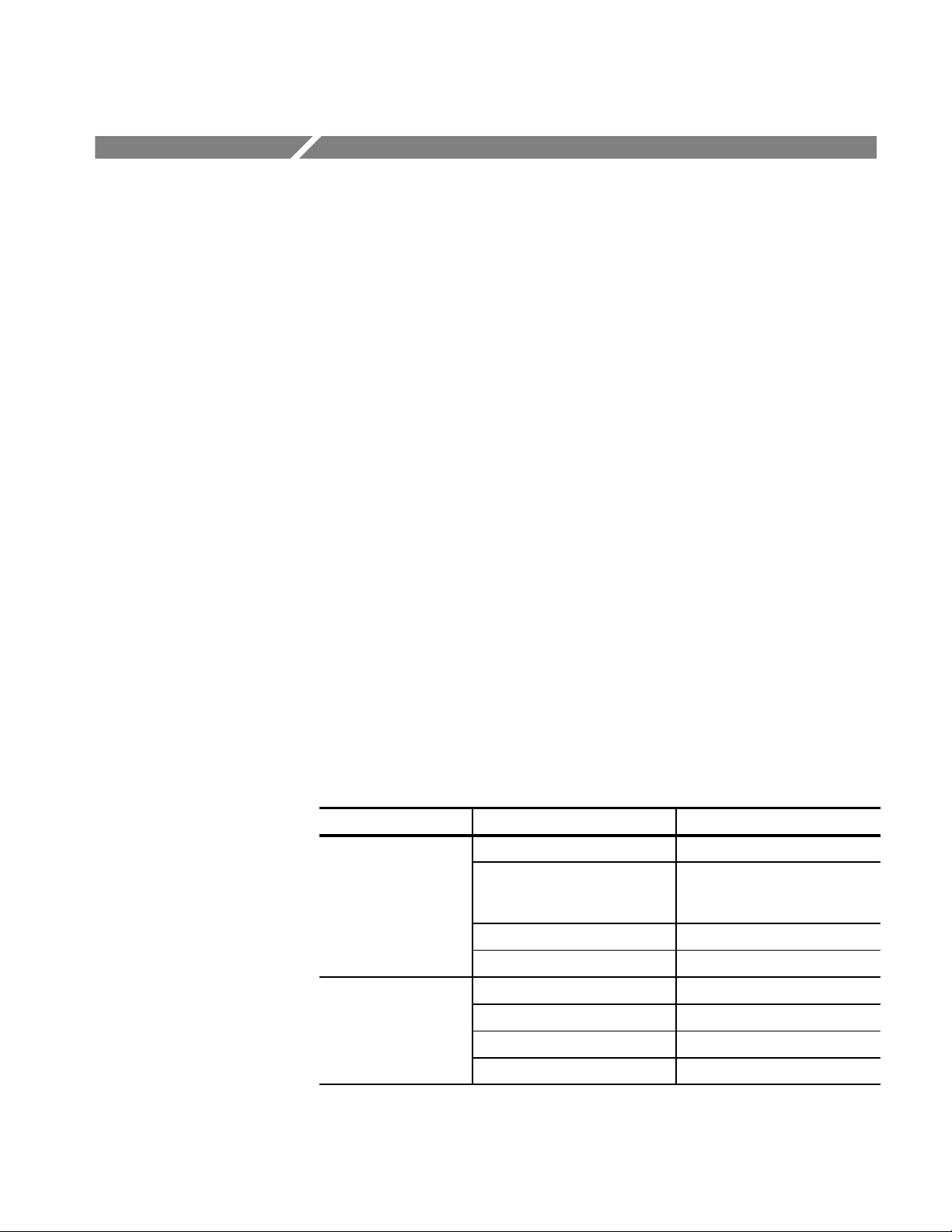
Application Notes
This section describes some of the typical measurement applications of the
AM 503B and AM 5030 Current Probe Amplifiers:
H Automobile Charging Systems
H Inductance Measurements
H Continuity Test of Multiple-Conductor Cable
H Measuring Inductor Turns Count
Automobile Charging Systems
Most automotive charging systems are three-phase alternators with a diode
rectifier network. A meter averages current from all three phases, and cannot
detect a single-phase diode problem. Observing the charge current waveform can
quickly reveal if one diode is shorted or open.
The diagram in Figure 3–6 shows the equipment setup. Refer to Table 3–2 for
the test equipment setup. An A6303 Current Probe was used for this high-current, low-voltage application. The A6303 is degaussed and clamped around the
positive battery lead from the alternator. The probe arrow is pointed away from
the alternator and toward the battery side of the circuit, to reflect conventional
current. The automobile is started and the lights are turned on to add a significant
load to the circuit.
T able 3–2: Automobile Charging Systems T est Setup
Instrument Control Setting
AM 503B and AM 5030 COUPLING DC
OUTPUT DC LEVEL 0V
(oscilloscope ground reference
line)
CURRENT/DIVISION 10 A
20MHz BW LIMIT off
Oscilloscope Coupling DC
Volts/Division 10 mV
Zero-Current Reference Center graticule line
Time Base 200 ms/division
AM 503B & AM 5030 Amplifier Instruction Manual 3–9
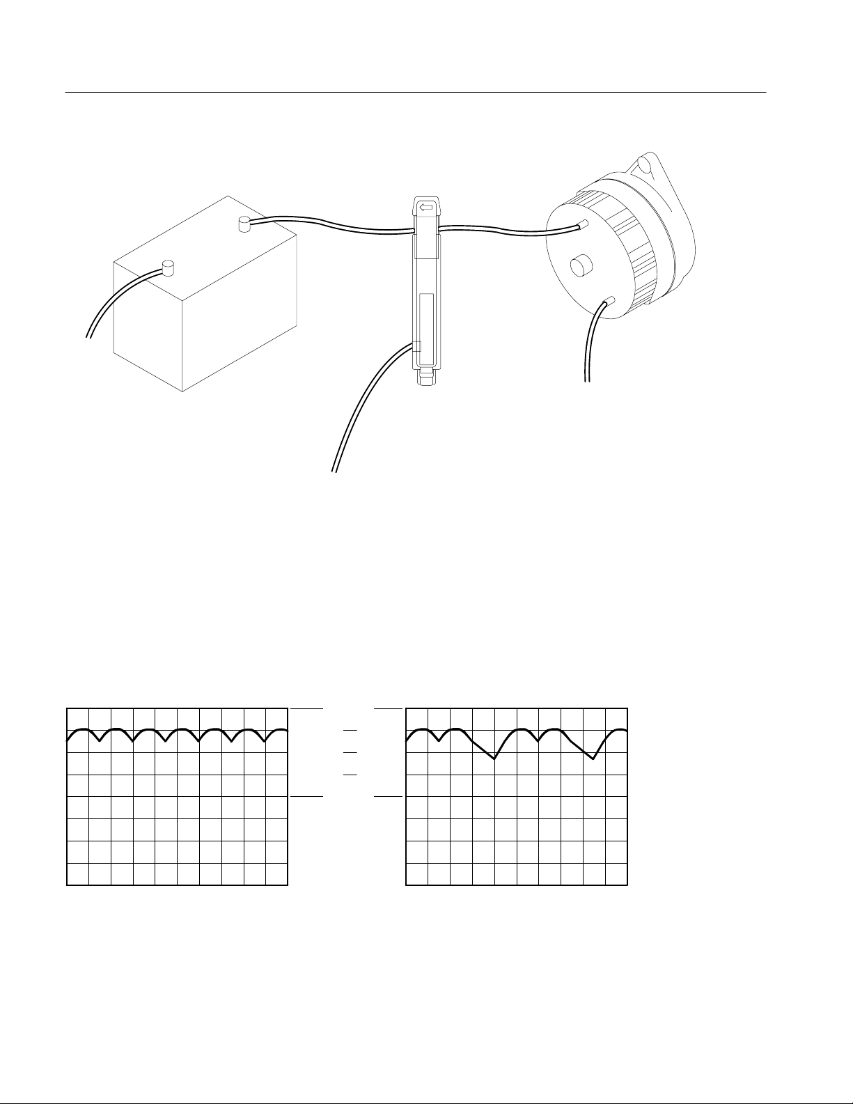
Application Notes
A6303
Battery Alternator
To
Ground
To Current Probe Amplifier
Figure 3–6: Setup for Measuring Charging Current
The waveform in Figure 3–7(a) shows the three-phase ripple frequency. The
average charge current is approximately 27 A with a minimum peak of approximately 23 A and a maximum peak of approximately 31 A. The waveform shows
a continuous cycle with no dropouts, so the alternator circuit appears to be
functioning properly. A single-phase diode failure normally appears as an
extreme drop in charge current every third cycle, as shown in Figure 3–7(b).
To Ground
40A
0A
(a) Normal Waveform (b) Waveform with One Bad Phase
Figure 3–7: Charge Current Waveforms
3–10 AM 503B & AM 5030 Amplifier Instruction Manual
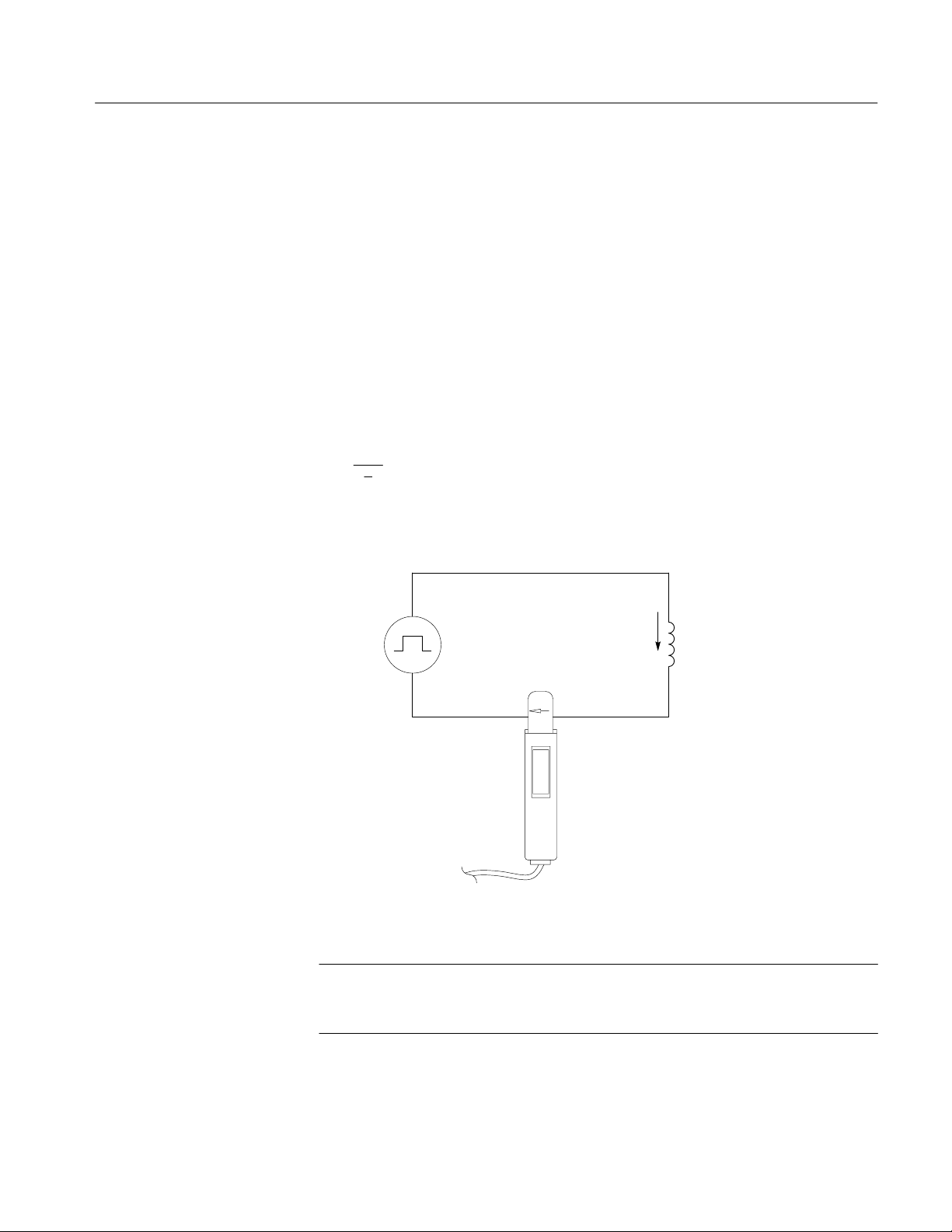
Inductance Measurements
You can use the AM 503B and AM 5030 to measure inductance of coils. Two
different methods can be used: one for low-impedance pulse sources and another
for high-impedance pulse sources of known value.
Application Notes
Low-Impedance Pulse
Sources
Figure 3–8 shows a measurement setup using a constant-voltage pulse generator
of extremely low output impedance. The inductor is connected across the output
terminals of the pulse source. The current probe is attached to one of the source
leads and the current ramp is measured.
The inductance is effectively defined by the slope of the current ramp, shown in
Figure 3–9, and is mathematically expressed by the following formula:
* E
L +
di
dt
where L is the inductance in henries, E is the voltage of the pulse generator, dt is
the change in time, and di is the change in current.
Current
Pulse
Generator
Flow (i)
Inductor
Current
Probe
Figure 3–8: Measuring Inductance with a Low-Impedance Source
NOTE. If the probe impedance is a significant part of the total circuit inductance,
measurement accuracy will be affected. Refer to the probe specifications for
probe insertion impedance.
AM 503B & AM 5030 Amplifier Instruction Manual 3–11
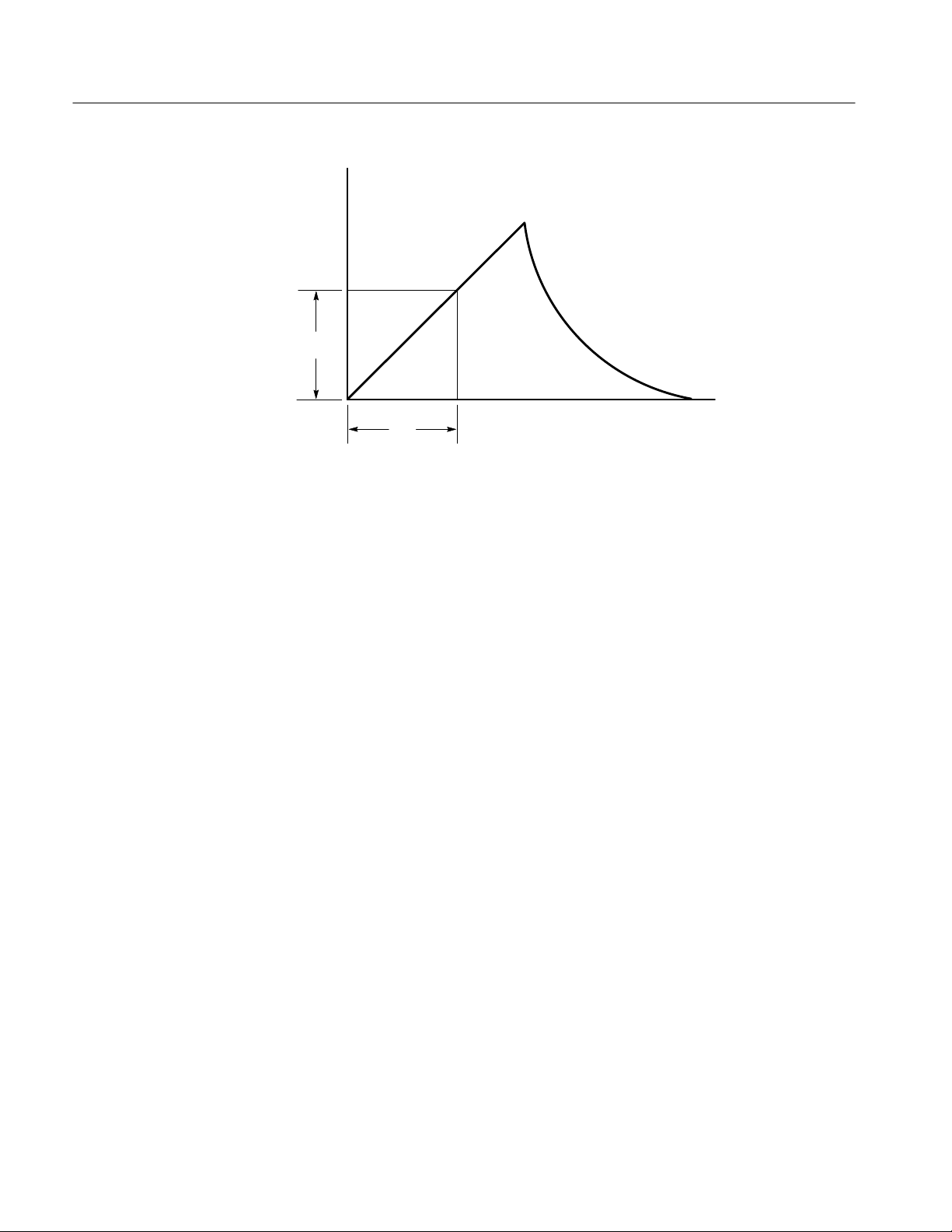
Application Notes
Current
Flow (i)
d
i
Time (t)
d
t
Figure 3–9: Linear Current vs. Time Ramp
High-Impedance Pulse
Sources
If the pulse source has a higher impedance of known resistance, such that the
output voltage drops as the current increases, the inductance of a coil can be
calculated by the time constant of the charge curve. Figure 3–10 shows the setup
diagram, which is similar to the previous example. The current ramp represented
in Figure 3–11 shows how the values for the inductance formula are obtained.
Use this formula to calculate the inductance based on the current measurement:
L + t R
where L is the inductance in henries, t is the time required for the current to rise
or fall 63.2% of the total current value, and R is the source resistance of the pulse
generator.
3–12 AM 503B & AM 5030 Amplifier Instruction Manual
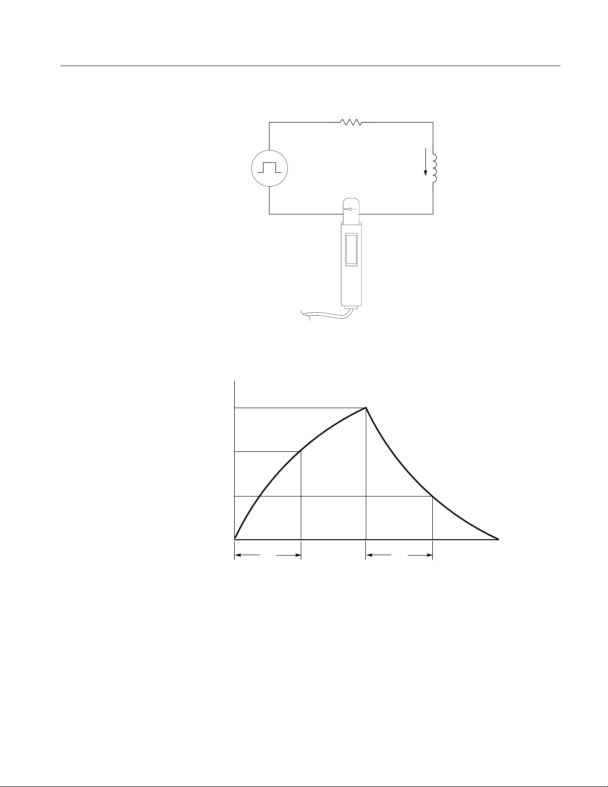
Application Notes
Resistance
Pulse
Generator
Current
Probe
L
Current
Flow (i)
Inductance
Figure 3–10: Measuring Inductance with a High-Impedance Source
Current
Flow (i)
100%
63.2%
36.8%
0
tt
Figure 3–11: High-Impedance Source Current Ramp
Time (t)
AM 503B & AM 5030 Amplifier Instruction Manual 3–13

Application Notes
Continuity Test of Multiple-Conductor Cable
Single conductors in a multiconductor cable can be tested with the AM 503B and
AM 5030. To check a conductor, clamp the current probe around the cable
bundle and check for a specific, known current signal. If there is no current or
the current is abnormally low, then the conductor has a continuity problem. If the
current is abnormally high, then the conductor may have a short to ground.
Measuring Inductor Turns Count
To obtain an approximate turns count of an inductor, connect the inductor to a
current limited source, as shown in Figure 3–12. Measure the input current on
one of the inductor leads, then clamp the current probe around the inductor and
note the current value. The number of turns is equal to the ratio of coil current to
input current. The accuracy of this method is limited by the current measurement
accuracy. The following method allows more precise turns measurement.
For a more precise turns count, you need a coil with a known number of turns to
use as a reference. The measurement setup is similar to the previously described
one, except the reference coil and the test coil are inserted into the current probe
so that the currents oppose each other (see Figure 3–13). You must observe the
polarity of coil current to determine whether the test coil has more or fewer turns
than the reference coil. The turns are calculated by using the formula:
I
N2+ N
m
1
I
1
where N2 is the number of turns in the test coil, N1 is the number of turns in the
reference coil, I
is the measured coil current, and I1 is the input current.
m
Measure Input Current Here
Current Flow (i)
Clamp probe
around coil to
Coil
measure
current from
coil turns
Figure 3–12: Measuring the Number of Turns in a Coil
3–14 AM 503B & AM 5030 Amplifier Instruction Manual
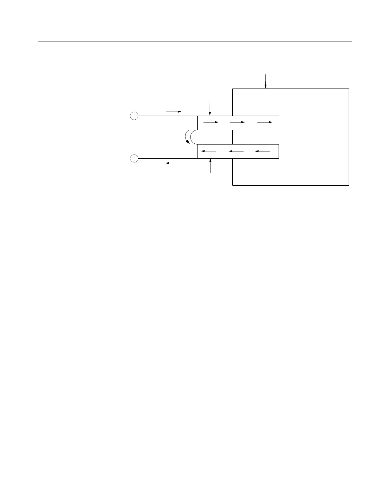
A6303 Current Probe
Current Flow
in Coil #1
Input Current
Current Flow
in Coil #2
Figure 3–13: T urns Measurement Using Reference Coil
Application Notes
AM 503B & AM 5030 Amplifier Instruction Manual 3–15

Application Notes
3–16 AM 503B & AM 5030 Amplifier Instruction Manual

Error Codes
During normal operation, the CURRENT/DIVISION readout of the AM 503B
and AM 5030 displays the scale factor or other setting such as the GPIB address.
If an instrument failure occurs, the display will flash an error code number.
Error Code 266
Error Code LO
Other Error Codes
The Amplifier displays error code 266 when the Amplifier output is not properly
terminated into a 50 load. Make sure your Amplifier OUTPUT is connected to
an oscilloscope input using a 50 BNC cable, and that the oscilloscope input is
set to 50 impedance. See Figure 1–1 on page 1–2 for proper cabling.
If your oscilloscope does not have 50 impedance settings for inputs, you can
place a 50 feedthrough termination on the oscilloscope input and connect the
Amplifier output cable to the termination. Do not place the feedthrough
termination at the Amplifier end of the BNC connecting cable.
When the internal backup battery becomes weak, the CURRENT/DIV display
will momentarily flash the characters LO when the instrument is turned on. For
battery replacement instructions, refer to Battery Replacement on page 7–10.
NOTE. If a battery low condition occurs, calibration values in NVRAM may be
lost, which can cause the the AM 503B and AM 5030 to fail to meet specifications.
If an error code other than 266 or LO appears, consult Table 3–3 for an explanation of the error. If the error is a hardware failure, turn the instrument off and
then on again. If the error condition persists, have the instrument serviced by a
qualified service person.
AM 503B & AM 5030 Amplifier Instruction Manual 3–17

Error Codes
T able 3–3: AM 503B and AM 5030 Front-Panel Error Codes
Error Number Description of Error
263 Probe opened during degauss/autobalance.
266 The Amplifier OUTPUT was not terminated into 50. It can also be caused by faulty hardware.
267 Internal buffer overflow .
350–354 Amplifier needs repair.
355 NVRAM failure, Amplifier reset to factory default. Will occur first power up after new firmware has been installed.
356 Amplifier needs repair .
357 or LO Internal battery is weak and needs replacement.
358 An error occurred while the Amplifier was restoring previously saved settings.
359 Probe needs repair; the Amplifier cannot recognize the probe type. Try removing and reconnecting the current
probe, and make sure it is locked.
360–362 Amplifier needs repair.
363–364 Amplifier or probe needs repair.
550–594
750–768
Error occurred during internal automatic adjustment. Repeated errors in the range 550–594 indicate the Amplifier
needs repair. 580 and 581 indicate that the Amplifier was unable to complete a probe of fset adjustment. See the
DC Offset Adjustment procedure for the particular probe you are using.
3–18 AM 503B & AM 5030 Amplifier Instruction Manual

Troubleshooting
Table 3–4 lists possible problems that you may encounter when measuring
current with the AM 503B and AM 5030. Use this as a quick troubleshooting
reference.
T able 3–4: Troubleshooting
Problem Remedy
Amplifier will not power up, though the TM
Series Power Module does power up.
Front panel displays error code 266. The Amplifier is not terminated into 50 . Set oscilloscope input impedance to 50 ,
Front panel displays error code 357 or LO.
Front panel displays an error code. Note the error code and turn the instrument off.
Cannot make a current measurement. Current Probe is not locked.
Cannot degauss the probe. Current Probe is not locked.
Stray DC component in measurement. Degauss the probe using the PROBE DEGAUSS AUTOBALANCE button. (The
Move the Amplifier to another slot in the TM Series Power Module.
(Power transistors in that position of the TM Series Power Module may be defective.
This may be the case even if other TM 500 or TM 5000 instruments work in that
position; not all instruments use the power module power transistors.)
and input coupling to DC. (If the oscilloscope input impedance is fixed at 1 M,
attach a 50 termination (see replaceable parts list) at the oscilloscope input. Do not
attach the termination at the Amplifier output.)
Battery is weak. Battery replacement should be performed by a qualified service
person.
Review installation and operating information in this manual.
Power up the instrument. If the error condition persists, refer the instrument to
qualified service personnel for repair.
Current Probe is improperly connected to the Amplifier input connector.
Coupling is set to REF position. Change to AC or DC.
Current Probe is improperly connected to the Amplifier input connector.
Current Probe has been overloaded, bumped, or exposed to magnetic field.)
AM 503B & AM 5030 Amplifier Instruction Manual 3–19

Troubleshooting
T able 3–4: Troubleshooting (Cont.)
Problem Remedy
Measurements are inaccurate. Degauss the probe.
The Amplifier output is not terminated into 50 load. Set the input impedance of
oscilloscope to 50 or connect a 50 feedthrough termination at the oscilloscope
input. Do not attach the termination at the Amplifier output.
Set the vertical amplifier of the oscilloscope to 10 mV/div.
Adjust the oscilloscope ground reference.
Adjust the Amplifier OUTPUT DC LEVEL control to the zero-current reference.
The measurement exceeds the maximum continuous current or Ampere-second
product ratings of the Current Probe. If possible, upgrade to a probe with a higher
current rating or use a CT-4 transformer.
Measurements roll off at high
frequencies.
The Amplifier or oscilloscope bandwidth limit is turned on. Verify that bandwidth limit
switches of both the Amplifier and the oscilloscope are set to the full bandwidth
position.
(Be careful not to exceed the frequency limit of the probe used. Frequencies above
the probe design may cause overheating and damage to the probe.)
Measurements exhibit excessive noise. Current Probe is not locked.
Current Probe is improperly connected to the Amplifier input.
Amplifier output is not terminated into 50 load. Set input impedance of oscilloscope
to 50 or connect a 50 feed-through termination at the oscilloscope input, not at
the Amplifier output.
Measurement aberrations exceed the specified
limit.
Measurements exhibit excessive delay or
slowed pulse response.
The Amplifier output is not terminated into 50 load. Set the input impedance of
oscilloscope to 50 or connect a 50 feedthrough termination (see the replaceable
parts list) at the oscilloscope input. Do not attach the termination to Amplifier output.
The measurement exceeds the maximum continuous current or Ampere-second
product ratings of the Current Probe. (For more information, see Current Limits on
page 3–4.) If possible, upgrade to a probe with a higher current rating or use a CT-4
transformer.
The Amplifier output is not terminated into 50 load. Set the input impedance of
oscilloscope to 50 or connect a 50 feedthrough termination (see the replaceable
parts list) at the oscilloscope input. Do not attach the termination to Amplifier output.
The measurement exceeds the Ampere-second product of the Current Probe. If
possible, upgrade to a probe with a higher current rating or use a CT-4 transformer.
Bandwidth limit is turned on. Verify that bandwidth limit switches of both the Amplifier
and the oscilloscope are set to the full bandwidth position.
3–20 AM 503B & AM 5030 Amplifier Instruction Manual

Specifications


Specifications
For additional probe specifications, refer to the probe’s Instructions.
These specifications are valid only under the following conditions:
H The probe and amplifier have been calibrated at an ambient temperature of
23_±5_ C.
H The probe and amplifier are operating in an environment whose limits are
described in Table 4–4 (the operating temperature limits are 0_ C to +50_ C,
unless otherwise stated).
H The probe and amplifier have had a warm-up period of at least 20 minutes.
H The probe degauss/autobalance routine has been performed after the
20-minute warm-up period, and thereafter whenever the PROBE
DEGAUSS/AUTOBALANCE light blinks.
H The Amplifier output is properly terminated into 50 .
Specifications are separated into two categories: warranted specifications and
nominal or typical characteristics.
Because of a change in the probe input connector, the performance specifications
are guaranteed only for probes having the following serial numbers:
A6312 All. . . . . .
A6302 B050000 and above. . . . . .
A6303 B022000 and above. . . . . .
A6302XL All. . .
A6303XL All. . .
A6304XL All. . .
Probes with earlier serial numbers can be updated; contact your nearest Tektronix
Service Center.
AM 503B & AM 5030 Amplifier Instruction Manual
4–1
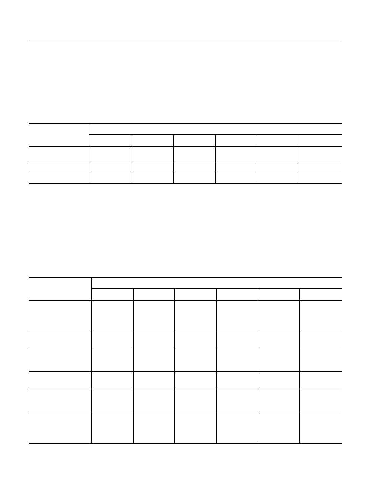
Specifications
P
P
Warranted Specifications
Warranted specifications, Table 4–1, are guaranteed performance specifications
unless specifically designated as typical or nominal.
T able 4–1: Warranted AM 503B and AM 5030 Specifications
Installed Probe
arameter
Bandwidth DC to 100 MHz,
Rise Time, 10% to 90% v3.5 ns v7 ns v23 ns v20 ns v35 ns v175 ns
DC Gain Accuracy ≤3%
1
The DC gain accuracy is correctable to < 0.2% when using the probe trim procedure described on page 2–10.
A6312
–3 dB
A6302 A6303 A6302XL A6303XL A6304XL
DC to 50 MHz,
–3 dB
1
≤3%
1
DC to 15 MHz,
–3 dB
≤3% ≤3%
DC to 17 MHz,
–3 dB
DC to 10 MHz,
–3 dB
1
≤3% ≤3%
DC to 2 MHz,
–3 dB
Nominal and Typical Characteristics
Nominal and typical characteristics, Tables 4–2 and 4–3, are not guaranteed.
They are provided to characterize the configuration, performance, or operation of
typical probe/amplifier combinations.
T able 4–2: Nominal and Typical AM 503B and AM 5030 Characteristics
Installed Probe
arameter
Current/Division Ranges,
nominal, Oscilloscope at
10 mV/div
Input Coupling, nominal AC, DC, and
AC Coupling LowFrequency Bandwidth,
typical
Output DC Level Adjustment Range, typical
Output Dynamic Range,
typical (Including Output
DC Level Setting)
Displayed Noise, typical <250 mA
A6312
1 mA/div to
5 A/div,
1–2–5
sequence
REF
<7 Hz, –3 dB <7 Hz, –3 dB <7 Hz, –3 dB <7 Hz, –3 dB <7 Hz, –3 dB <7 Hz, –3 dB
±10 divisions ±10 divisions ±10 divisions ±10 divisions ±10 divisions ±10 divisions
±10 divisions,
±100 mV
RMS
Limit measurement bandwidth
to 100 MHz.
A6302 A6303 A6302XL A6303XL A6304XL
1 mA/div to
5 A/div,
1–2–5
sequence
AC, DC, and
REF
±10 divisions,
±100 mV
<250 mA
Limit measurement bandwidth
to 100 MHz.
RMS
5 mA/div to
50 A/div,
1–2–5
sequence
AC, DC, and
REF
±10 divisions,
±100 mV
<2.5 mA
Limit measurement bandwidth
to 100 MHz.
RMS
1 mA/div to
5 A/div,
1–2–5
sequence
AC, DC, and
REF
±10 divisions,
±100 mV
<250 mA
Limit measurement bandwidth
to 100 MHz.
RMS
5 mA/div to
50 A/div,
1–2–5
sequence
AC, DC, and
REF
±10 divisions,
±100 mV
<2.5 A
Limit measurement bandwidth
to 100 MHz.
RMS
500 mA/div to
200 A/div,
1–2–5
sequence
AC, DC, and
REF
±10 divisions,
±100 mV
<0.25 A
Limit measurement bandwidth
to 20 MHz.
RMS
4–2
AM 503B & AM 5030 Amplifier Instruction Manual
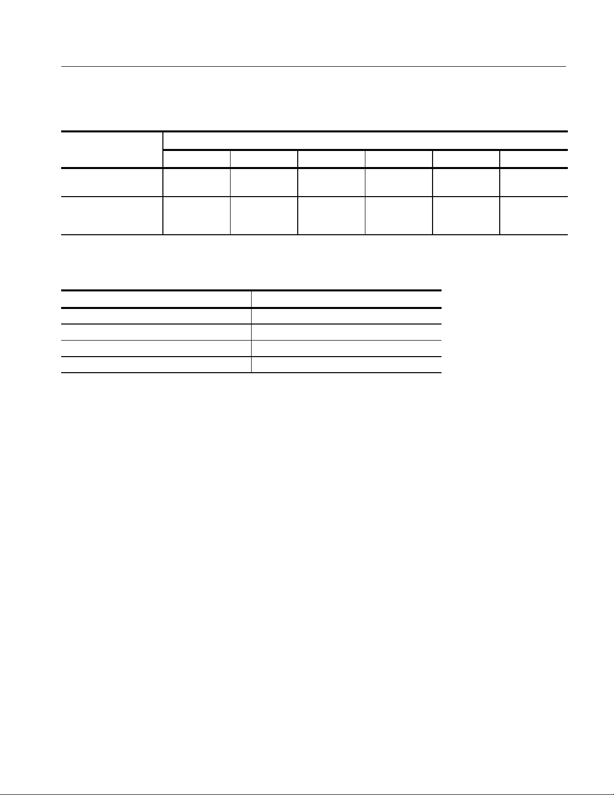
T able 4–2: Nominal and Typical AM 503B and AM 5030 Characteristics (Cont.)
Installed Probe
Parameter
Parameter A6304XLA6303XLA6302XLA6303A6302A6312
Specifications
Bandwidth Limit, –3 dB,
typical
Signal Delay, typical,
with provided 50
cable
20 MHz
±4 MHz
approximately
30 ns
20 MHz
±4 MHz
approximately
30 ns
12 MHz
±3 MHz
approximately
55 ns
T able 4–3: AM 503B and AM 5030 Mechanical Characteristics
Parameter, nominal Characteristic
Length 298 mm (11.7 in)
Height 127 mm (5.0 in)
Width 67 mm (2.63 in)
Weight 2 kg (4.4 lb)
14 MHz
±2 MHz
approximately
60 ns
9 MHz
±2 MHz
approximately
105 ns
2 MHz
±10 kHz
approximately
105 ns
AM 503B & AM 5030 Amplifier Instruction Manual
4–3
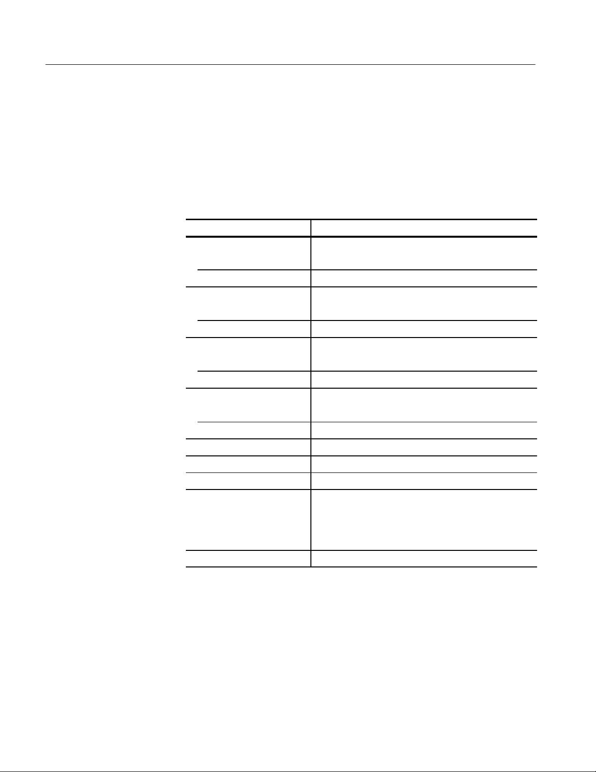
Specifications
Environmental Characteristics
The environmental characteristics in Table 4–4 are warranted performance
specifications. Unlike the warranted characteristics in Table 4–1, the environmental characteristics are type tested; therefore there are no performance
verification procedures provided to test these characteristics.
T able 4–4: AM 503B and AM 5030 Environmental Characteristics
Parameter Characteristic
Ambient Temperature
Operating 0_ C to +50_ C
Nonoperating –55_ C to +75_ C
Humidity
Operating 50_ C, to 95% R.H.
Nonoperating 60_ C, to 95% R.H.
Altitude
Operating 4,570 m (15,000 ft) maximum
Nonoperating 15,200 m (50,000 ft) maximum
Random Vibration
Operating 0.31 g
Nonoperating 2.46 g
Shock 30 g, 11ms duration, half-sine pulses
Bench Handling 30g, 11ms duration, half-sine pulses
Topple Test 30g, 11 ms duration, half-sine pulses
Transit Test, Packaged Product 38.1 cm (15 in) free-fall drop height,
91 kg (200 lb) compressive load,
32 mm (0.125 in) displacement,
30 minute vibration test,
1.33 g
Electro-Magnetic Compliance Meets FCC Part 15, Subpart B, Class A
, 5 Hz to 500 Hz, 10 minutes each axis
RMS
, 5 Hz to 500 Hz, 10 minutes each axis
RMS
, 1 hour each axis random vibration test
RMS
4–4
AM 503B & AM 5030 Amplifier Instruction Manual

Warning
The following servicing instructions are for use only by qualified personnel. To
avoid personal injury, do not perform any servicing other than that contained in
the operating instructions unless you are qualified to do so. Refer to General
Safety Summary and Service Safety Summary prior to performing any service.

 Loading...