

Page 1

Instructions
AM 503B, AM 5030 & A6300 Series
067-0271-00 Verification and Adjustment Kit
070-9352-01
This document applies to firmware version 3.0
and above.
Warning
The servicing instructions are for use by qualified
personnel only. To avoid personal injury, do not
perform any servicing unless you are qualified to
do so. Refer to all safety summaries prior to
performing service.
Page 2

Copyright T ektronix, Inc. All rights reserved.
T ektronix products are covered by U.S. and foreign patents, issued and pending. Information in this publication supercedes
that in all previously published material. Specifications and price change privileges reserved.
Printed in the U.S.A.
T ektronix, Inc., P.O. Box 1000, Wilsonville, OR 97070–1000
TEKTRONIX and TEK are registered trademarks of T ektronix, Inc.
Page 3

Table of Contents
General Safety Summary iii. . . . . . . . . . . . . . . . . . . . . . . . . . . . . . . . . . . .
Service Safety Summary vii. . . . . . . . . . . . . . . . . . . . . . . . . . . . . . . . . . . . .
Kit Description 1. . . . . . . . . . . . . . . . . . . . . . . . . . . . . . . . . . . . . . . . . . . . .
Kit Parts List 1. . . . . . . . . . . . . . . . . . . . . . . . . . . . . . . . . . . . . . . . . . . . . . . . . . . .
Equipment Required 1. . . . . . . . . . . . . . . . . . . . . . . . . . . . . . . . . . . . . . . . . . . . . . .
AM 503B and AM 5030 Performance Verification 3. . . . . . . . . . . . . . .
T est Procedure Conditions 3. . . . . . . . . . . . . . . . . . . . . . . . . . . . . . . . . . . . . . . . . .
DC Gain Accuracy 4. . . . . . . . . . . . . . . . . . . . . . . . . . . . . . . . . . . . . . . . . . . . . . . .
DC Balance 9. . . . . . . . . . . . . . . . . . . . . . . . . . . . . . . . . . . . . . . . . . . . . . . . . . . . .
RMS Noise 10. . . . . . . . . . . . . . . . . . . . . . . . . . . . . . . . . . . . . . . . . . . . . . . . . . . . . .
Bandwidth 12. . . . . . . . . . . . . . . . . . . . . . . . . . . . . . . . . . . . . . . . . . . . . . . . . . . . . .
Degauss 14. . . . . . . . . . . . . . . . . . . . . . . . . . . . . . . . . . . . . . . . . . . . . . . . . . . . . . . .
GPIB Installation 15. . . . . . . . . . . . . . . . . . . . . . . . . . . . . . . . . . . . . . . . . . .
Assemble GPIB Test Fixture 15. . . . . . . . . . . . . . . . . . . . . . . . . . . . . . . . . . . . . . . .
Remove Side Covers 16. . . . . . . . . . . . . . . . . . . . . . . . . . . . . . . . . . . . . . . . . . . . . .
Install GPIB T est Fixture 17. . . . . . . . . . . . . . . . . . . . . . . . . . . . . . . . . . . . . . . . . . .
AM 503B and AM 5030 Adjustments 19. . . . . . . . . . . . . . . . . . . . . . . . . .
Amplifier Setup 19. . . . . . . . . . . . . . . . . . . . . . . . . . . . . . . . . . . . . . . . . . . . . . . . . .
Calculate and Load New Calibration Constants 20. . . . . . . . . . . . . . . . . . . . . . . . .
GPIB Removal (AM 503B Only) 21. . . . . . . . . . . . . . . . . . . . . . . . . . . . . . . . . . . .
Performance Verification Setup for Current Probes 23. . . . . . . . . . . . . .
T est Procedure Conditions 23. . . . . . . . . . . . . . . . . . . . . . . . . . . . . . . . . . . . . . . . . .
Equipment Preparation 23. . . . . . . . . . . . . . . . . . . . . . . . . . . . . . . . . . . . . . . . . . . . .
W arranted Specifications 24. . . . . . . . . . . . . . . . . . . . . . . . . . . . . . . . . . . . . . . . . . .
A6312 Performance Verification 25. . . . . . . . . . . . . . . . . . . . . . . . . . . . . .
Required Test Equipment 25. . . . . . . . . . . . . . . . . . . . . . . . . . . . . . . . . . . . . . . . . . .
Bandwidth 26. . . . . . . . . . . . . . . . . . . . . . . . . . . . . . . . . . . . . . . . . . . . . . . . . . . . . .
Rise Time 28. . . . . . . . . . . . . . . . . . . . . . . . . . . . . . . . . . . . . . . . . . . . . . . . . . . . . . .
DC Gain Accuracy 30. . . . . . . . . . . . . . . . . . . . . . . . . . . . . . . . . . . . . . . . . . . . . . . .
A6302 and A6302XL Performance Verification 35. . . . . . . . . . . . . . . . . .
Required Test Equipment 35. . . . . . . . . . . . . . . . . . . . . . . . . . . . . . . . . . . . . . . . . . .
Bandwidth 36. . . . . . . . . . . . . . . . . . . . . . . . . . . . . . . . . . . . . . . . . . . . . . . . . . . . . .
Rise Time 38. . . . . . . . . . . . . . . . . . . . . . . . . . . . . . . . . . . . . . . . . . . . . . . . . . . . . . .
DC Gain Accuracy 40. . . . . . . . . . . . . . . . . . . . . . . . . . . . . . . . . . . . . . . . . . . . . . . .
A6303 and A6303XL Performance Verification 45. . . . . . . . . . . . . . . . . .
Required Test Equipment 45. . . . . . . . . . . . . . . . . . . . . . . . . . . . . . . . . . . . . . . . . . .
Bandwidth 46. . . . . . . . . . . . . . . . . . . . . . . . . . . . . . . . . . . . . . . . . . . . . . . . . . . . . .
Rise Time 48. . . . . . . . . . . . . . . . . . . . . . . . . . . . . . . . . . . . . . . . . . . . . . . . . . . . . . .
DC Gain Accuracy 50. . . . . . . . . . . . . . . . . . . . . . . . . . . . . . . . . . . . . . . . . . . . . . . .
A6304XL Performance Verification 55. . . . . . . . . . . . . . . . . . . . . . . . . . .
Required Test Equipment 55. . . . . . . . . . . . . . . . . . . . . . . . . . . . . . . . . . . . . . . . . . .
Rise Time 56. . . . . . . . . . . . . . . . . . . . . . . . . . . . . . . . . . . . . . . . . . . . . . . . . . . . . . .
Bandwidth 58. . . . . . . . . . . . . . . . . . . . . . . . . . . . . . . . . . . . . . . . . . . . . . . . . . . . . .
DC Gain Accuracy 58. . . . . . . . . . . . . . . . . . . . . . . . . . . . . . . . . . . . . . . . . . . . . . . .
AM 503B, AM 5030, and A6300 Series Verification and Adjustment
i
Page 4

Table of Contents
Adjustment Procedures for Current Probes 63. . . . . . . . . . . . . . . . . . . . .
A6312, A6302 and A6302XL Adjustment 65. . . . . . . . . . . . . . . . . . . . . . .
Required Test Equipment 65. . . . . . . . . . . . . . . . . . . . . . . . . . . . . . . . . . . . . . . . . . .
A6312, A6302 and A6302XL DC Offset Adjustment 65. . . . . . . . . . . . . . . . . . . . .
A6303 and A6303XL Adjustments 69. . . . . . . . . . . . . . . . . . . . . . . . . . . .
Required Test Equipment 69. . . . . . . . . . . . . . . . . . . . . . . . . . . . . . . . . . . . . . . . . . .
A6303 and A6303XL DC Offset Adjustment 70. . . . . . . . . . . . . . . . . . . . . . . . . . .
A6303 and A6303XL Transient Response and Gain Adjustment 72. . . . . . . . . . . .
A6304XL Adjustments 75. . . . . . . . . . . . . . . . . . . . . . . . . . . . . . . . . . . . . .
Required Test Equipment 75. . . . . . . . . . . . . . . . . . . . . . . . . . . . . . . . . . . . . . . . . . .
A6304XL DC Offset Adjustment 76. . . . . . . . . . . . . . . . . . . . . . . . . . . . . . . . . . . .
DC Gain Adjustment 78. . . . . . . . . . . . . . . . . . . . . . . . . . . . . . . . . . . . . . . . . . . . . .
A6304XL Transient Response Adjustment 80. . . . . . . . . . . . . . . . . . . . . . . . . . . . .
ii
AM 503B, AM 5030, and A6300 Series Verification and Adjustment
Page 5

General Safety Summary
Review the following safety precautions to avoid injury and prevent damage to
this product or any products connected to it.
Only qualified personnel should perform service procedures.
While using this product, you may need to access other parts of the system. Read
the General Safety Summary in other system manuals for warnings and cautions
related to operating the system.
Injury Precautions
Ground the Product
Do Not Operate Without
Covers
Do Not Operate in
Wet/Damp Conditions
Do Not Operate in
Explosive Atmosphere
Avoid Exposed Circuitry
This product is grounded through the grounding conductor of the power cord. To
avoid electric shock, the grounding conductor must be connected to earth
ground. Before making connections to the input or output terminals of the
product, ensure that the product is properly grounded.
To avoid electric shock or fire hazard, do not operate this product with covers or
panels removed.
To avoid electric shock, do not operate this product in wet or damp conditions.
To avoid injury or fire hazard, do not operate this product in an explosive
atmosphere.
To avoid injury, remove jewelry such as rings, watches, and other metallic
objects. Do not touch exposed connections and components when power is
present.
AM 503B, AM 5030, and A6300 Series Verification and Adjustment
iii
Page 6

General Safety Summary
Product Damage Precautions
Use Proper Power Source
Use Proper Voltage
Setting
Provide Proper Ventilation
Do Not Operate With
Suspected Failures
Do not operate this product from a power source that applies more than the
voltage specified.
Before applying power, ensure that the line selector is in the proper position for
the power source being used.
To prevent product overheating, provide proper ventilation.
If you suspect there is damage to this product, have it inspected by qualified
service personnel.
Safety Terms and Symbols
Terms in This Manual
These terms may appear in this manual:
WARNING. Warning statements identify conditions or practices that could result
in injury or loss of life.
Terms on the Product
iv
CAUTION. Caution statements identify conditions or practices that could result in
damage to this product or other property.
These terms may appear on the product:
DANGER indicates an injury hazard immediately accessible as you read the
marking.
WARNING indicates an injury hazard not immediately accessible as you read the
marking.
CAUTION indicates a hazard to property including the product.
AM 503B, AM 5030, and A6300 Series Verification and Adjustment
Page 7

General Safety Summary
Symbols on the Product
The following symbols may appear on the product:
DANGER
High Voltage
Certifications and Compliances
CSA Certified Power
Cords
Safety Certification of
Plug-in Modules
CSA Certification includes the products and power cords appropriate for use in
the North America power network. All other power cords supplied are approved
for the country of use.
For plug-in modules that are safety certified by Underwriters Laboratories, UL
Listing applies only when the module is installed in a UL Listed product. CSA
Certification applies only when the module is installed in a CSA Certified
product.
Protective Ground
(Earth) T erminal
ATTENTION
Refer to Manual
Double
Insulated
AM 503B, AM 5030, and A6300 Series Verification and Adjustment
v
Page 8

General Safety Summary
vi
AM 503B, AM 5030, and A6300 Series Verification and Adjustment
Page 9

Service Safety Summary
Only qualified personnel should perform service procedures. Read this Service
Safety Summary and the General Safety Summary before performing any service
procedures.
Do Not Service Alone
Disconnect Power
Use Care When Servicing
With Power On
Do not perform internal service or adjustments of this product unless another
person capable of rendering first aid and resuscitation is present.
To avoid electric shock, disconnect the main power by means of the power cord
or, if provided, the power switch.
Dangerous voltages or currents may exist in this product. Disconnect power,
remove battery (if applicable), and disconnect test leads before removing
protective panels, soldering, or replacing components.
To avoid electric shock, do not touch exposed connections.
AM 503B, AM 5030, and A6300 Series Verification and Adjustment
vii
Page 10

Service Safety Summary
viii
AM 503B, AM 5030, and A6300 Series Verification and Adjustment
Page 11
Kit Description
Kit Parts List
This kit includes parts and instructions for verifying and adjusting the AM 503B
and AM 5030 Current Probe Amplifiers. The recommended calibration interval
is one year.
These instructions assume a certain familiarity with the AM 503B and AM 5030
amplifiers. For servicing information, refer to the AM 503B & AM 5030
Instruction Manual (070-8766-XX).
Before you begin the AM 503B or AM 5030 amplifiers, assemble the test
equipment required and determine if a full calibration is necessary. None of the
components contained in this kit require calibration.
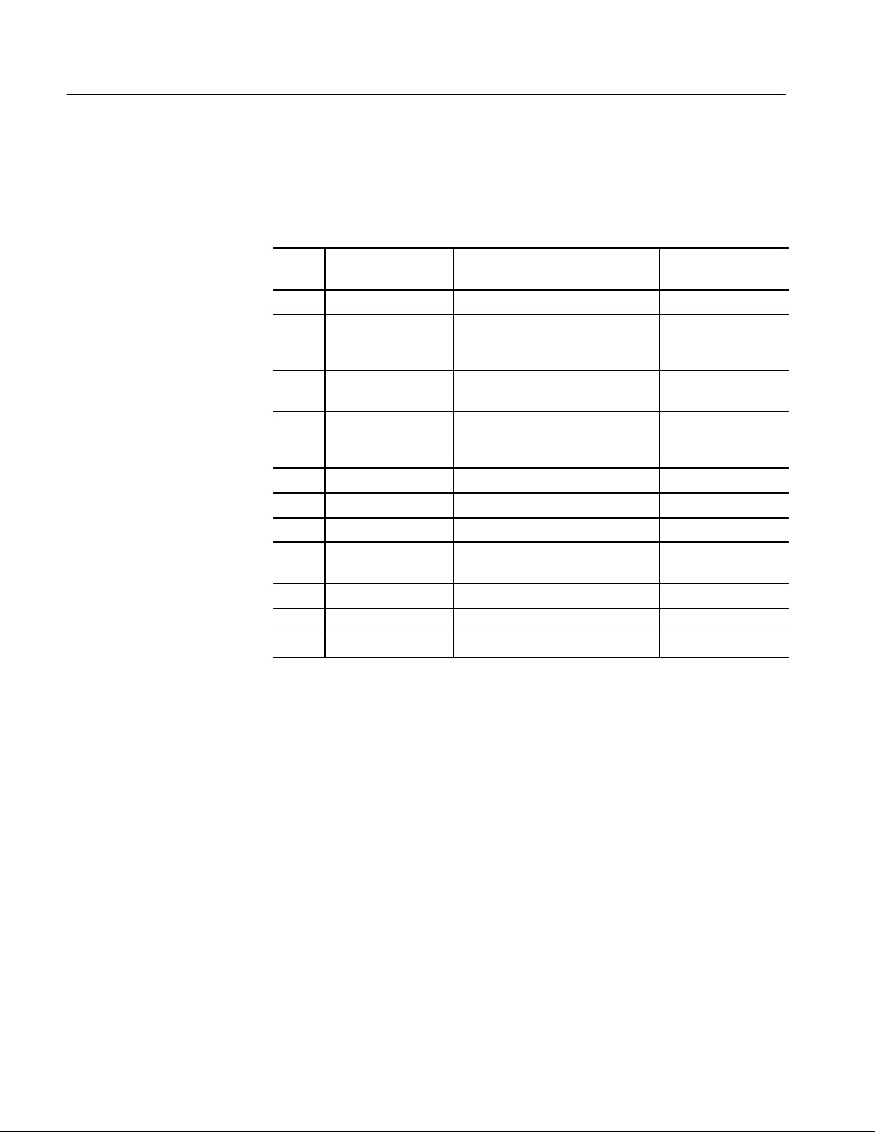
This kit includes the parts listed in Table 1.
T able 1: Kit Parts List
Tektronix Part Number Quantity Description
015-0598-00 1 Voltage adapter
Equipment Required
015-0670-00 1 Feed-thru adapter
129-0425-00 2 Spacer, post: 0.9 L, 4-40 thru, 0.25 hex
174-2314-00 1 Ribbon cable
21 1-0408-00 6 Screw, assem wshr: 4-40 X 0.250, T-10 Torx
220-0729-00 1 Nut block: 4-40 X 0.188
679-2836-02 1 GPIB board
070-9352-XX 1 Calibration Kit Manual
The installation procedure requires a T-10 Torx screwdriver and a flat-blade
screwdriver.
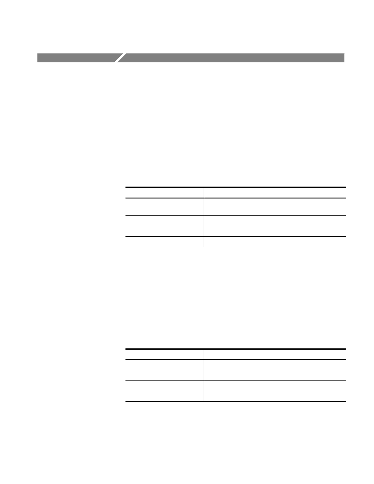
The performance verification and adjustment procedures require the test
equipment listed in Table 2. The test equipment must meet or exceed the
AM 503B, AM 5030, and A6300 Series Verification and Adjustment
1
Page 12
Kit Description
specifications listed. You may need to modify the test procedures if you do not
use the recommended equipment.
T able 2: Required Test Equipment
Recommended
Qty Item Description
1 Oscilloscope 500 MHz bandwidth TDS 520B
Equipment
1 Leveled Sine Wave
Generator
1 Digital Multimeter 0.20%, 31/2 digit resolution, range
1 Current Source 0.1%, 0 to ±1 A Fluke 5700A or
1 Calibration Fixture 50 , BNC Connector 015-0601-50
1 Termination 50 ±0.1%, 0.5 W 01 1-0129-00
2 BNC Cables 50 , 1.05m (42in) long 012-0057-01
2 BNC to Dual
Banana Adapters
1 Feed-thru Fixture supplied with kit 015-0670-00
1 Voltage Adapter supplied with kit 015-0598-00
1 Current Probe
1
Required for functional test only.
1
3 MHz to 100 MHz Wavetek 9100 with
Option 250 or SG 503
equivalent.
DM2510/G or
±50 mV
Fluke 850x/884x
Wavetek 9100 with
Option 250
103-0090-00
A6302
2
AM 503B, AM 5030, and A6300 Series Verification and Adjustment
Page 13
AM 503B and AM 5030 Performance Verification
Refer to the list of equipment required in Table 2 on page 2. Set up the AM 503B
or AM 5030 amplifiers as follows:
1. Plug the AM 503B or AM 5030 amplifier into the TM 5000 mainframe.
2. Power the amplifier on and let it warm up at least 20 minutes.
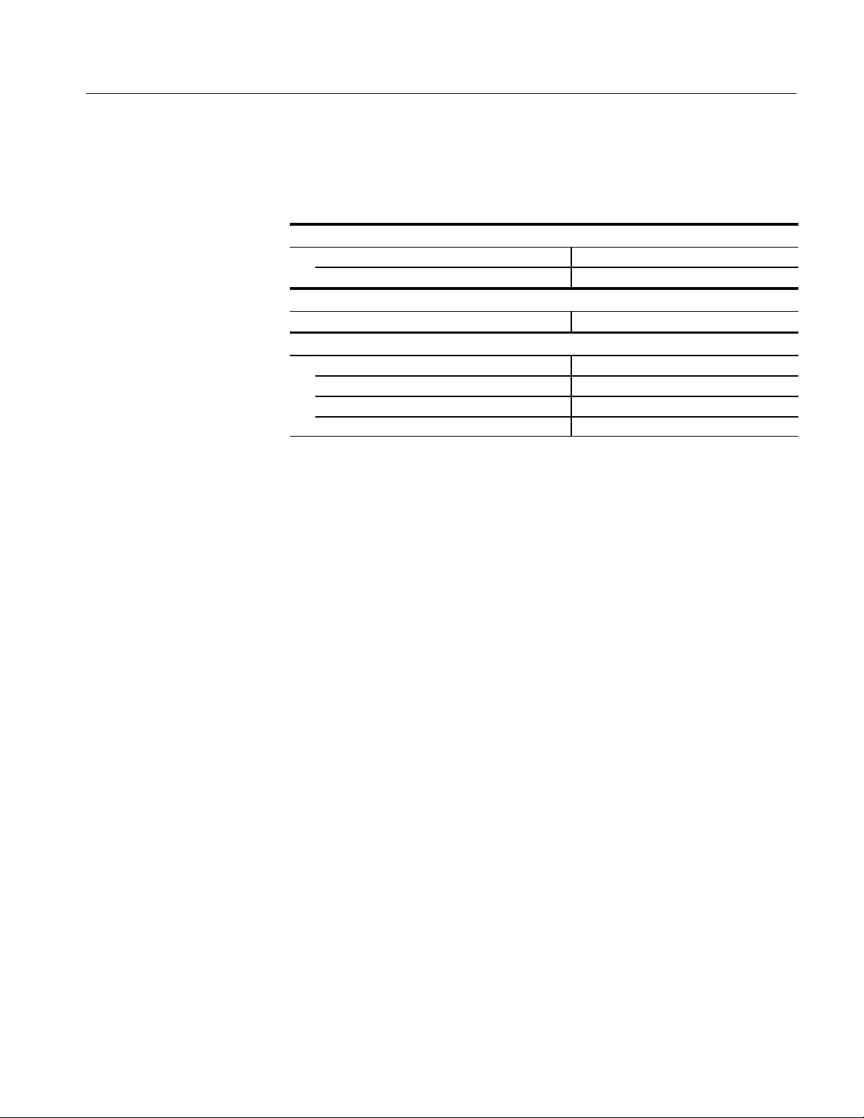
The procedures in this section verify that the AM 503B or AM 5030 amplifier
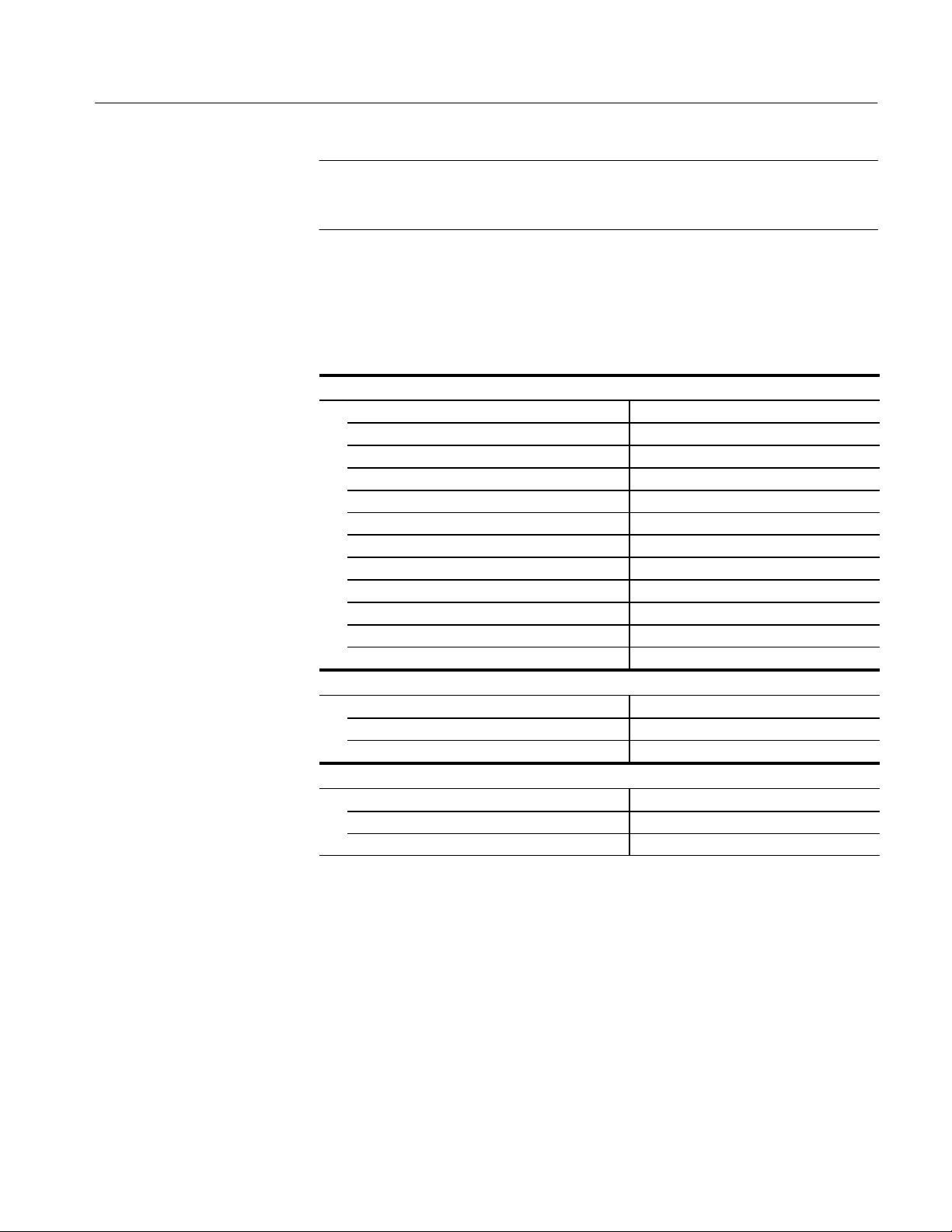
meets the warranted specifications listed in Table 3.
T able 3: AM 503B and AM 5030 Warranted Specifications
Parameter Characteristic
DC Gain Accuracy ≤ 1.5% after DC accuracy measurement and cal constant
loading.
DC Balance ± 2 mV
RMS Noise ≤ 250 A (2.5 mV)
Bandwidth ≥ 100 MHz
Test Procedure Conditions
These procedures are valid only under the following conditions:
H The system has been calibrated at an ambient temperature of 23_ ±5_ C.
H The system is operating in an environment whose limits are described in
T able 4: AM 503B and AM 5030 Environmental Characteristics
Parameter Characteristic
Ambient Temperature
Humidity
H The system, including probe, has had a warm-up period of at least
Table 4.
Operating 0_ C to +50_ C
Operating 50_ C, to 95% R.H.
20 minutes.
AM 503B, AM 5030, and A6300 Series Verification and Adjustment
3
Page 14

AM 503B and AM 5030 Performance Verification
DC Gain Accuracy
Use the following procedure to verify the DC gain accuracy of the amplifier.
Test Equipment Setup
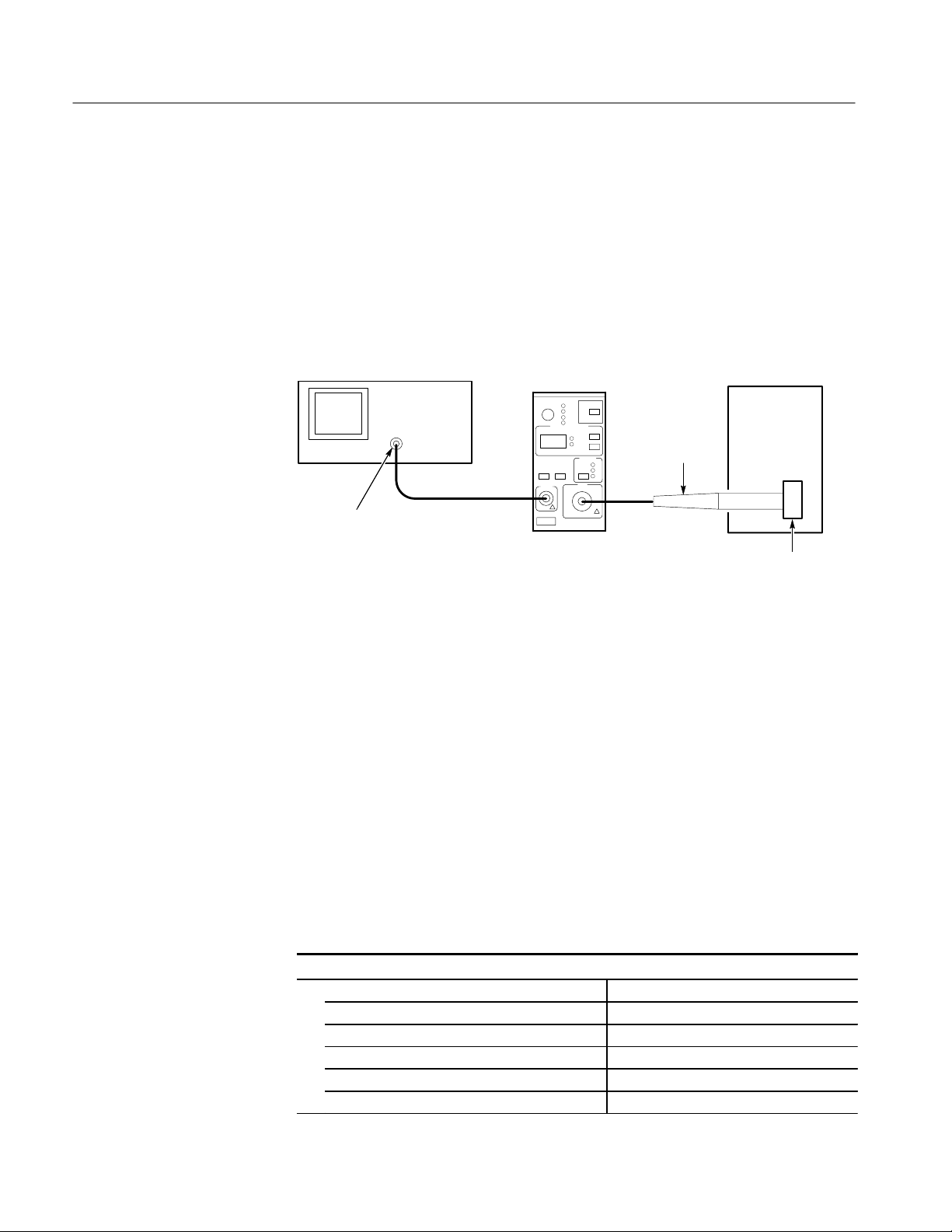
Refer to Figure 1 and set up the test equipment as follows:
1. Connect the output of the amplifier to the DMM.
a. Connect a BNC Cable from the AM 503B/AM 5030 OUTPUT to the
50 feedthrough termination.
b. Attach the termination to a BNC-to-dual banana adapter.
c. Observe polarity and insert the dual banana adapter into the digital
multimeter DC voltage input.
2. Connect the input to current source.
a. Connect the other BNC cable from the Voltage Adapter to a BNC-to-
dual banana adapter.
b. Observe polarity and insert the dual banana adapter into the current
source DC output. Do not connect the voltage adapter to the amplifier at
this time.
Amplifier in TM
Series Power
Module
DMM
Current
Source
+–
BNC to Dual
Banana Adapter
50 T ermination
50 Coaxial
Cable
+–
Feed-Thru Fixture
Voltage Adapter
BNC to Dual
Banana Adapter
Figure 1: Test Equipment Setup
4
AM 503B, AM 5030, and A6300 Series Verification and Adjustment
Page 15
AM 503B and AM 5030 Performance Verification
3. Make or verify the equipment settings in Table 5:
T able 5: Equipment Settings
Digital Multimeter
Measurement Type DC volts
Range Autoranging
Current Source
Output Off
AM 503B and AM 5030 Amplifier
Coupling DC
BW Limit On (20MHz)
Current/division 10 mA/division
Probe Trim 000
Procedure
After the equipment is set up, proceed as follows:
1. Connect the feed-thru fixture (015-0670-00) to the INPUT of the AM 503B/
AM 5030 amplifier and press the PROBE DEGAUSS AUTOBALANCE
button. Wait for the degauss/autobalance routine to complete before
proceeding. The routine is complete when the indicator light turns off.
2. Remove the feed-thru fixture from the INPUT of the amplifier and connect
the Voltage Adapter (015-0598-00) to the INPUT of the amplifier. Do not
press the PROBE DEGAUSS AUTOBALANCE button again even though
the indicator is flashing.
3. For each of the current/division settings in Table 6, perform the following
steps. Remember that any errors that develop here will affect the final DC
gain accuracy calculations at the end.
a. Set the Amplifier to the desired current/division setting from Table 6.
b. Set the current source to the correct positive test current using Table 6.
c. Turn on the current source.
d. Record the exact measurement of the digital multimeter as M
. (You can
1
copy Table 7 on page 8 to record the results of your measurements.)
e. Set the current source for the correct negative test current using Table 6.
AM 503B, AM 5030, and A6300 Series Verification and Adjustment
5
Page 16

AM 503B and AM 5030 Performance Verification
T able 6: DC Gain Accuracy Calibration Test for the AM503X
AM 503B and AM 5030
Current/Division
1 m A ±100 A 10 mA
2 m A ±200 A 20 mA
5 m A ±500 A 50 mA
10 m A ±1mA 100 mA
20 m A ±2mA 200 mA
50 m A ±5mA 500 mA
100 m A ±10mA 1 A
200 m A ±20mA 2 A
500 m A ±50mA 5 A
1 A ±100 mA 10 A
2 A ±100 mA 10 A
Current Source Output Test Current (It)
5 A ±100 mA 10 A
f. Record the digital multimeter reading as M2.
g. Calculate the measured current (I
I
m
M1–M
2
(currentdivision)
0.01
) using the following formula:
m
For example, you might have obtained values of 51.0 mV for M1 and
–53.0 mV for M
sion, you can compute I
(51.0x10
I
m
. If you are using an Amplifier setting of 10 mA/divi-
2
as:
m
–3
) – (–53.0x10⁻³)
0.01
(10x10–3) 104 mA
6
AM 503B, AM 5030, and A6300 Series Verification and Adjustment
Page 17

AM 503B and AM 5030 Performance Verification
h. Calculate the %Error between the measured current (I
current (I
%Error +
) %Error as follows:
t
I
* I
m
t
100
I
t
) and the test
m
For example, using a test current It of 100 mA and a measured current I
of 104 mA, the %Error would be:
%Error +
104 – 100
100
100 +)4%
NOTE. It is important that the correct polarity be used in order to calculate the
% error
4. Copy the work sheet in Table 7 and fill it in with required data. Calculate the
values for each New Rin Cal Constant only if adjustment is required.
m
AM 503B, AM 5030, and A6300 Series Verification and Adjustment
7
Page 18
AM 503B and AM 5030 Performance Verification
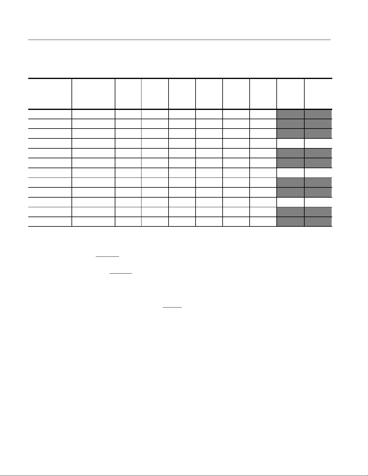
T able 7: Work Sheet for DC Gain Accuracy Calibration
AM 503B and
AM 5030
Current/
Division
Current/Voltage
Source Output
Test
Current
I
t
I
m
M
1
M
2
(Note A)
%Error
(Note B)
Rin
Name
1mA ±100 A 10 mA
2mA ±200 A 20 mA
5mA ±500 A 50 mA
10 mA ±1mA 100 mA Rin1X
20 mA ±2mA 200 mA
50 mA ±5mA 500 mA
100 mA ±10 mA 1 A Rin10X
200 mA ±20 mA 2 A
500 mA ±50 mA 5 A
1 A ±100 mA 10 A Rin100X
2 A ±100 mA 10 A
5 A ±100 mA 10 A
Note A
Note B
M2* M
+
I
m
0.01
%Error +
1
(currentńdivision)
* I
I
m
t
100
I
t
Note C Query amplifier for existing Rin1X, Rin10X, and Rin100X Cal Constants
(CALC? 00, CALC? 01, and CALC? 02 respectively).
Note D
New Rin Cal Constant + (1 )
%Error
100
) Existing Rin Cal c onstant
(Calculate this value only if adjustment is required.)
Existing
Cal
Constant
(Note C)
New
Cal
Constant
(Note D)
8
AM 503B, AM 5030, and A6300 Series Verification and Adjustment
Page 19

DC Balance
AM 503B and AM 5030 Performance Verification
5. Verify that the measured DC gain accuracy is within ±1.5% at all settings.
NOTE. If the % Error on any of the settings is greater than ±1.5%, you must
perform the Cal Constant loading sequence. Refer to the adjustment procedure
that begins on page 19.
This procedure checks the DC Balance Test of the AM 503B and AM 5030.
1. Connect a BNC cable from the AM 503B/AM 5030 amplifier OUTPUT to
the 50 feedthrough termination. Attach the termination to a BNC-to-dual
banana adapter.
2. Taking care to observe and maintain polarity, insert the dual banana adapter
into the digital multimeter DC voltage input. Refer to Figure 2.
Amplifier in TM
Series Power
Module
DMM
+–
BNC to Dual
Banana Adapter
50 Termination
50 Coaxial
Cable
Voltage Adapter
Figure 2: Setup for DC Balance
3. Connect the Voltage Adapter (015-0598-00) to the INPUT of the amplifier
and disconnect the other end of the Voltage Adapter from ALL other sources.
In other words, the BNC end of the Voltage adapter should not be connected
up to any thing.
4. Make or verify the equipment settings in Table 8.
AM 503B, AM 5030, and A6300 Series Verification and Adjustment
9
Page 20

AM 503B and AM 5030 Performance Verification
T able 8: Equipment Settings for DC Balance
Digital Multimeter
Measurement Type DC volts
Range Autoranging
AM 503B and AM 5030 Amplifier
Coupling REF
BW Limit On (20MHz)
Current/division 1 mA/division
5. Press the PROBE DEGAUSS AUTOBALANCE button. Wait for the
degauss/autobalance routine to complete before proceeding. The routine is
complete when the indicator light turns off.
6. For each of the Amplifier settings (AC, DC, 1 mA, 2 mA, 5 mA, 10 mA,
20 mA, 50 mA, 100 mA, 200 mA, 500 mA, 1 A, 2 A, 5 A), perform the
following steps.
RMS Noise
a. Set the amplifier to the desired setting from above.
b. Measure the exact DC voltage with the digital multimeter.
c. Verify that the measured DC voltage is less than ±2mV (0.2 divs).
This procedure tests the RMS noise level of the AM 503B and AM 5030 Current
Probe Amplifier. In this test you measure the RMS voltage of the amplifier
output when the amplifier is set to the most sensitive setting and BW LIMIT is
off. Refer to Figure 4 when making equipment connections.
Amplifier in TM
Test Oscilloscope
Series Power
Module
Voltage Adapter
10
50 oscilloscope input (or add 50
termination here if oscilloscope has
only high-impedance input).
Figure 3: RMS Noise Test Setup for stand alone AM 503B/AM 5030
AM 503B, AM 5030, and A6300 Series Verification and Adjustment
Page 21

AM 503B and AM 5030 Performance Verification
1. Using a 50 W BNC cable, connect the Amplifier OUTPUT to a 50 W
oscilloscope input. If the input impedance of your oscilloscope is 1 MW,
connect a 50 W feedthrough termination at the oscilloscope input. Do not
connect the termination at the Amplifier output.
2. Connect the Voltage Adapter to the Amplifier INPUT.. The other end of the
Voltage Adapter should not be connected to anything.
3. Make or verify the equipment settings in Table 9.
T able 9: Equipment Settings for RMS Noise Check
Oscilloscope
Vertical input impedance 50
Vertical gain 10 mV/division
Time base 2 us/division
Record length 500
Coupling DC
Offset 0 V (mid-scale)
Trigger type Edge
Trigger mode Auto
Trigger position 50%
Acquisition mode Sample
Bandwidth 100 MHz
Measurement type RMS
AM 503B and AM 5030
Coupling DC
BW Limit Off (full bandwidth)
Current/division 1 mA/division
4. Press the Amplifier PROBE DEGAUSS AUTOBALANCE button. Wait
for the degauss/autobalance routine to complete before proceeding. The
routine is complete when the indicator light turns off.
5. Set the Oscilloscope couping to AC.
6. Using the RMS measurement capability of the oscilloscope, measure the
RMS reading, and verify that it is less than 250 mA (2.5 mV).
AM 503B, AM 5030, and A6300 Series Verification and Adjustment
11
Page 22

AM 503B and AM 5030 Performance Verification
Bandwidth
This procedure tests the bandwidth of the AM 503B and AM 5030. In this test
you measure a signal at a relatively low frequency and again at the upper test
frequency. The two measurements are compared to verify that the signal
amplitude does not fall below a certain limit. Refer to Figure 4 when making
equipment connections.
Leveled
Sine Wave
Generator
Output
Test Oscilloscope
50 oscilloscope input (or add 50
termination here if oscilloscope has
only high-impedance input).
Amplifier in TM
Series Power
Module
Voltage Adapter
Figure 4: Bandwidth Test Setup
1. Using a 50 W BNC cable, connect the Amplifier OUTPUT to a 50 W
oscilloscope input. If the input impedance of your oscilloscope is 1 MW,
connect a 50 W feedthrough termination at the oscilloscope input. Do not
connect the termination at the Amplifier output.
2. Connect the Voltage Adapter to the Amplifier INPUT.
3. Make or verify the equipment settings in Table 10:
12
T able 10: Equipment Settings for Bandwidth Check
Oscilloscope
Vertical input impedance 50
Vertical gain 10 mV/division
Time base 100 ns/division
Record length 500
Coupling DC
Offset 0 V (mid-scale)
Trigger type Edge
Trigger mode Auto
Trigger position 50%
Acquisition mode Average
AM 503B, AM 5030, and A6300 Series Verification and Adjustment
Page 23

AM 503B and AM 5030 Performance Verification
T able 10: Equipment Settings for Bandwidth Check (Cont.)
Oscilloscope
Number of waveforms to average 16
Measurement type Peak-to-Peak
Leveled Sine Wave Generator
Frequency 3MHz
Amplitude 3.0 V
AM 503B and AM 5030
Coupling DC
BW Limit Off (full bandwidth)
Current/division 500 mA/division
p-p
4. Press the Amplifier PROBE DEGAUSS AUTOBALANCE button. Wait
for the degauss/autobalance routine to complete before proceeding. The
routine is complete when the indicator light turns off.
5. Connect the BNC cable from the output of the leveled sine wave generator to
the BNC end of the Voltage Adapter.
6. Adjust the signal generator output so that the Amplifier output is approximately 60 mV
, or six graticule divisions on the oscilloscope.
p-p
7. Using the peak-peak measurement capability of the oscilloscope, measure
and record the peak-peak reading as M
.
1
8. Set the oscilloscope time base to 5 ns/division. Increase the signal generator
frequency to 100 MHz, the upper test frequency.
9. Using the peak-peak measurement capability of the oscilloscope, measure
and record the peak-peak reading as M
.
2
10. The system meets the bandwidth specification if the ratio of the signal
amplitude at the warranted bandwidth is at least 70% of the signal amplitude
at 3 MHz. Using the following calculation, verify system bandwidth:
M
2
ǒ
Ǔ
u 0.707
M
1
AM 503B, AM 5030, and A6300 Series Verification and Adjustment
13
Page 24

AM 503B and AM 5030 Performance Verification
Degauss
This is only a functional test of the degauss operation. Refer to Figure 5.
1. Connect a current probe to the output of the AM 503B or AM 5030.
2. Press the Amplifier PROBE DEGAUSS AUTOBALANCE button. Wait
for the indicator light to turn off.
3. Verify that there are no error codes.
Test Oscilloscope
Amplifier in TM
Series Power
Module
Current Probe
50 Input
Figure 5: Setup for Degaussing the Current Probe
This completes the performance verification.
If the AM 503B or AM 5030 amplifier fails any of the verification tests, refer to
the AM 503B and AM 5030 Instruction Manual for servicing information.
14
AM 503B, AM 5030, and A6300 Series Verification and Adjustment
Page 25

GPIB Installation
WARNING. Instrument disassembly should only be performed by qualified service
personnel.
This section details how to assemble the GPIB test fixture and install it in the
AM 503B Current Probe Amplifier prior to performing the adjustment procedure. The AM 503B amplifier requires the GPIB test fixture in order to set the
internal calibration constants. After the adjustment procedure is complete, you
must remove the test fixture.
The AM 5030 amplifier already contains a GPIB board. If you are calibrating an
AM 5030 amplifier, disregard this section and proceed with the adjustment
procedure on page 19.
CAUTION. GPIB installation should only be performed by qualified service
personnel.
Assemble GPIB Test Fixture
Use the following procedure to assemble the GPIB test fixture. Once you
assemble the fixture, you can use it to calibrate any number of AM 503B
amplifiers.
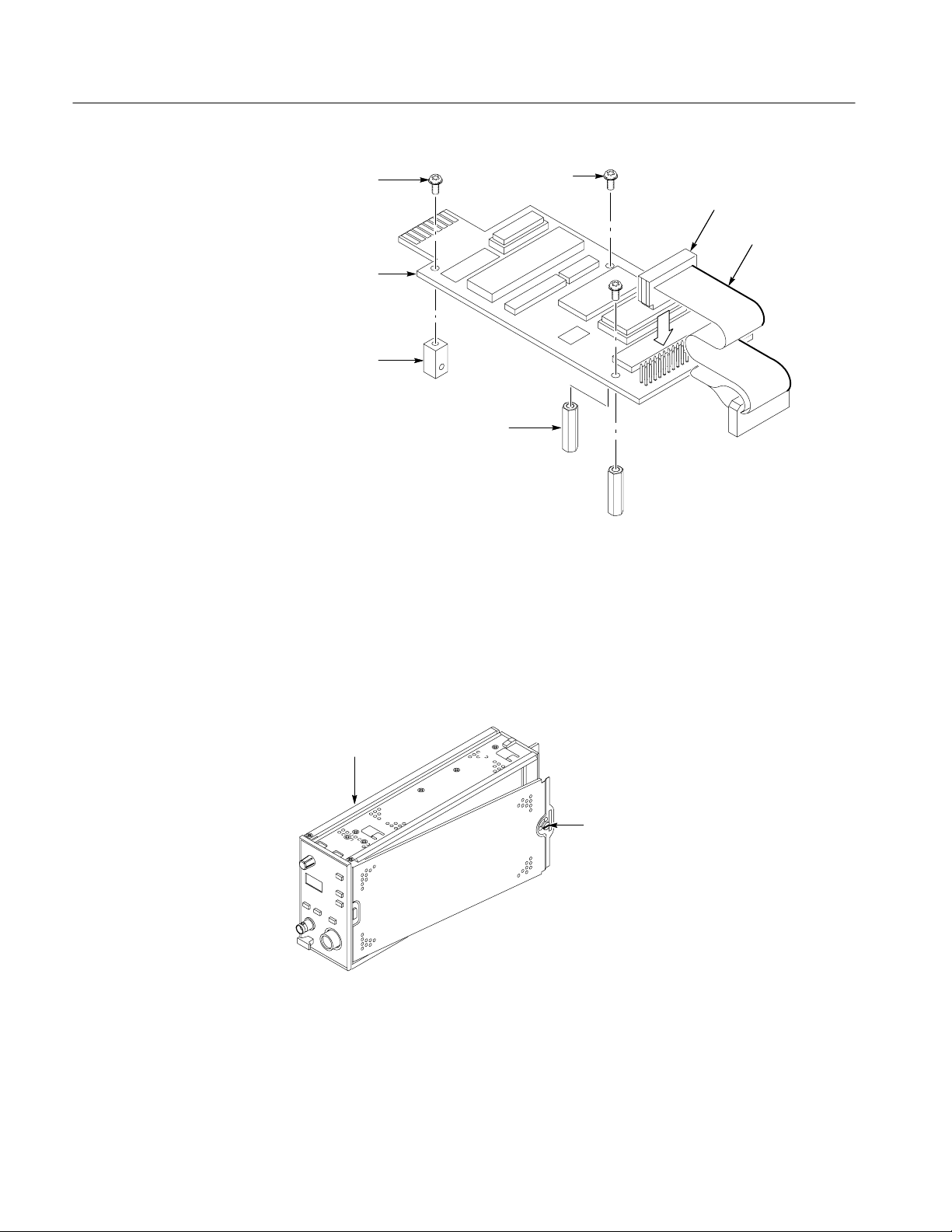
1. Refer to Figure 6. Install the spacers (129-0425-00) onto the GPIB board
with two screws (210-0408-00).
2. Install the ribbon cable (174-2314-00) onto the GPIB with the RED edge
oriented as shown. (The tabbed end of the connector connects to the main
board of the AM 503B amplifier.)
3. Install nut block (220-0729-00) onto the GPIB board with one screw
(210-0408-00).
AM 503B, AM 5030, and A6300 Series Verification and Adjustment
15
Page 26
GPIB Installation
Screw
GPIB Board
Nut Block
Spacers (2)
Screws (2)
Figure 6: Assembling the GPIB Test Fixture
Ribbon Cable
Red Edge
Remove Side Covers
Refer to Figure 7 and unlatch the securing screws with a flat-blade screwdriver.
Remove both covers from the AM 503B and set them to one side.
Amplifier
Securing Screw
Figure 7: Removing the AM 503B Side Covers
16
AM 503B, AM 5030, and A6300 Series Verification and Adjustment
Page 27
Install GPIB Test Fixture
GPIB Installation
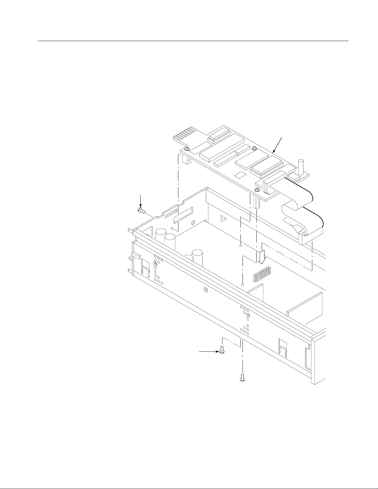
Refer to Figure 8 and install the GPIB test fixture on the AM 503B main board.
1. Install the tabbed end of the ribbon cable (174-2314-00) onto the main board
keeping the RED edge towards rail.
GPIB Board
Screw
Screws (2)
Figure 8: Installing the GPIB Test Fixture
AM 503B, AM 5030, and A6300 Series Verification and Adjustment
17
Page 28

GPIB Installation
CAUTION. To avoid damaging the circuits, make sure the connectors are properly
aligned with the pins. Check to be sure all pins are connected.
2. Dress the excess ribbon cable back under the GPIB board and insert the end
of the board with the gold contacts into the slot of the rear frame.
3. Align the spacers of the test fixture over the holes on the main circuit board.
a. Install two screws (210-0408-00) through the main board to both
spacers.
b. Install one screw (210-0408-00) through the rear frame to the nut block
on the GPIB board.
This completes the GPIB installation. Remove the GPIB test fixture and reinstall
the side covers after the adjustment procedure is complete.
18
AM 503B, AM 5030, and A6300 Series Verification and Adjustment
Page 29

AM 503B and AM 5030 Adjustments
The adjustment procedure consists of a series of steps to determine and set the
proper calibration constants of the AM 503B and AM 5030 Current Probe
Amplifiers.
NOTE. To set the internal calibration constants of the AM 503B amplifier, you
must install the GPIB test fixture. Refer to the procedure that begins on page 15.
Amplifier Setup
Set up the AM 503B or AM 5030 amplifiers as follows:
1. Plug the AM 503B or AM 5030 into the TM 5000 mainframe.
2. Power the amplifier on and let it warm up at least 20 minutes. The amplifier
must be calibrated at an ambient temperature between 25 ±5_ C.
3. Enable the Cal Mode of the amplifier by sending the following command
over the GPIB interface:
NOTE. You must send the command in order to load the calibration
constants.
4. On the AM 5030 amplifier only, send the query and verify that the
serial number is correct.
If the serial number of the AM 5030 amplifier is not correct, perform the
following steps:
a. Send the following command over the GPIB interface:
!
Be sure to hit the space bar twice before entering the serial number
(i.e. ).
b. Send the query again to verify that the serial number of the
AM 5030 is now correct.
AM 503B, AM 5030, and A6300 Series Verification and Adjustment
19
Page 30

AM503B and AM5030 Adjustments
Calculate and Load New Calibration Constants
Use the following procedure to calculate and load new calibration (cal) constants
for Rin1X, Rin10X and Rin100X.
NOTE. Perform this procedure only if the amplifier fails the DC Gain Accuracy
test on page 4.
1. Query amplifier for existing Rin1X, Rin10X, and Rin100X Cal Constants
(, , and respectively). Enter these values in
Table 7 on page 8.
2. For each Existing Rin Cal Constant entered in Table 7 on page 8, calculate
the New Rin Cal Constants using the following formulas:
New Rin Cal Constant + (1 )
%Error
100
) Existing Rin Cal Constant
For example, having a %Error of +4.0% at 10 mA and an Existing
Rin1X Cal Constant of 25500 would translate into a New Rin Cal
Constant as follows:
New Rin Cal Constant + (1 )
) 4.0
) 25500 + 26520
100
NOTE. The Rin Cal Constants must be five digit numbers.
3. Enter the New Cal Constant for each of the three settings, Rin1X, Rin10X,
and Rin100X in Table 7 on page 8.
4. Over the GPIB interface load the New Rin Cal Constants:
a. Send the command:
The parameter, , is the Cal Constant for Rin 1X
from Table 7.
For example, using the New Rin1X calculated above of 26520, the GPIB
command sent to the amplifier would be as follows:
20
This will load the Rin1X with the new calibration constant to fine tune
the DC gain accuracy of the amplifier.
b. Send the command:
AM 503B, AM 5030, and A6300 Series Verification and Adjustment
Page 31

AM503B and AM5030 Adjustments
The parameter, , is the New Cal Constant for
Rin 10X from Table 7.
c. Over the GPIB interface send the following command to the amplifier:
The parameter, is the New Cal Constant for
Rin 100X from Table 7.
d. Verify the Cal Constants by sending the following commands:
e. Connect a feed-thru adapter to the input of the amplifier and send the
command:
NOTE. It is important to use the feed-thru adapter and the DEGAuss 1 command;
otherwise the gain check will not work
5. Repeat the DC Gain Accuracy check on page 4.
GPIB Removal (AM 503B Only)
Remove the GPIB test fixture from the AM503B amplifier only. The GPIB
board of the AM 5030 remains with the amplifier. Refer to Figure 8 on page 17
and use the following procedure:
1. Power the amplifier off and remove amplifier from the TM 5000 mainframe.
2. Remove the screw from the rear frame.
3. Remove the two screws from the bottom of the main board that connect to
the spacers of the test fixture.
4. Remove the GPIB Test Fixture Board
5. Disconnect the tabbed end of the ribbon cable (174-2314-00) from the main
board. Leave the cable attached to the GPIB board.
6. Reinstall the side covers on the amplifier.
7. Store the test fixture with standoffs and cable intact.
This completes the adjustment procedure.
AM 503B, AM 5030, and A6300 Series Verification and Adjustment
21
Page 32

AM503B and AM5030 Adjustments
22
AM 503B, AM 5030, and A6300 Series Verification and Adjustment
Page 33

Performance Verification Setup for Current Probes
The Performance Verification tests allow you to demonstrate that the A6300
Series Current Probe meets its specified levels of performance. The recommended calibration interval is one year.
An AM 503B or AM 5030 Current Probe Amplifier that meets the tolerances of
the AM 503B and AM 5030 Performance Verification Procedure (page 3) can be
used as a standard for calibrating the current probes. Since the amplifier and
probe are designed as a system with known performance characteristics, it is not
necessary for the amplifier to meet the 4:1 uncertainty ratio that is normally
recommended for calibrations. To calibrate probes using an AM 503B or
AM 5030 as a standard, follow the performance verification procedures in these
instructions or in the AM 503B and AM 5030 Instruction Manual.
No probe or Amplifier adjustments are required during these test procedures.
Should any test fail, refer to the troubleshooting section in the AM 503B and
AM 5030 Instruction Manual for recommendations.
Tolerances that are specified in these procedures apply to the Amplifier and
current probe and do not include test equipment error.
Test Procedure Conditions
These procedures are valid only under the following conditions:
H The system has been calibrated at an ambient temperature of 25_±5_ C.
H The system is operating in an environment whose limits are described in
H The system, including probe, has had a warm-up period of at least
H The probe degauss/autobalance routine has been performed after the
Equipment Preparation
Before performing the verification tests, install all plug-in units into the power
module and turn the power on. Turn any remaining equipment on and allow the
entire system, including the attached probe, to warm up for a minimum of 20
minutes.
Table 4 on page 3.
20 minutes.
20-minute warm-up period.
AM 503B, AM 5030, and A6300 Series Verification and Adjustment
23
Page 34

Performance Verification Setup for Current Probes
arameter
NOTE. Before performing any verification procedure, properly degauss the
probe. Remove the probe from any current-carrying conductor, lock the probe,
and press the Amplifier PROBE DEGAUSS AUTOBALANCE button. The
degauss/autobalance routine is complete when the indicator light turns off.
The Amplifier front panel will display an error code 266 during the degauss/
autobalance routine if the Amplifier is not properly terminated into 50 . Verify
that the oscilloscope input is 50 and set to DC coupling. Use a 50
feedthrough termination, attached at the oscilloscope input, if necessary.
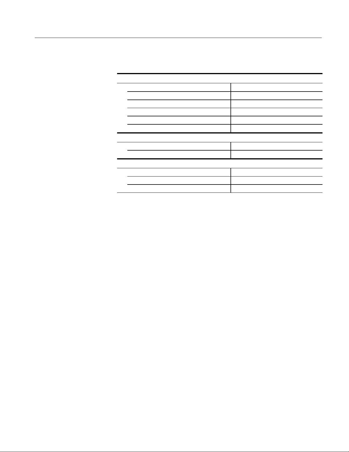
Warranted Specifications
Warranted specifications, Table 11, are guaranteed performance specifications
unless specifically designated as typical or nominal.
T able 11: Warranted AM 503B and AM 5030 Specifications
Installed Probe
P
Bandwidth DC to 100 MHz,
Rise Time, 10% to 90% 3.5 ns 7 ns 23 ns 20 ns 35 ns 175 ns
DC Gain Accuracy 3% 3% 3% 3% 3% 3%
A6312 A6302 A6303 A6302XL A6303XL A6304XL
–3 dB
DC to 50 MHz,
–3 dB
DC to 15 MHz,
–3 dB
DC to 17 MHz,
–3 dB
DC to 10 MHz,
–3 dB
DC to 2 MHz,
–3 dB
24
AM 503B, AM 5030, and A6300 Series Verification and Adjustment
Page 35

A6312 Performance Verification
The test procedures in this section verify proper performance of the A6312
current probe.
Read page 23 before starting these procedures. Also, read each procedure
through completely before starting to ensure proper completion.
Required Test Equipment
To perform the acceptance tests in this section, you will need the test equipment
listed in Table 12. The test equipment must meet or exceed the specifications
listed. The test procedures may need to be modified if the recommended
equipment is not used.
T able 12: Required Test Equipment
Qty Item Description
1 Oscilloscope 500 MHz bandwidth TDS 520B
Recommended
Equipment
1 Current Probe
Amplifier
1 Leveled Sine Wave
Generator
1 Calibration Generator 1 MHz square wave, rise time <1 ns,
1 Digital Multimeter 0.25% 31/2 digit resolution
1 Current Source 0.3% accuracy, 0 to ±2 A Fluke 5700A or
1 Calibration Fixture 50 , BNC Connector 015-0601-50
1 Current Loop 20 turns 27 AWG coated wire Refer to page 40.
1 Termination 50 ±0.1%, 0.5 W 01 1-0129-00
1 BNC Cable 50 , 1.05m (42in) long 012-0057-01
1 BNC to Dual
Banana Adapter
3 MHz to 100 MHz Wavetek 9100 with
1V
into 50
p-p
at ± 50 mV
AM503B or AM5030
Option 250 or
SG 503 equivalent.
Wavetek 9100 with
Option 250 or
PG 506A equivalent
DM2510/G or
Fluke 850x/884x
Wavetek 9100 with
Option 250
103-0090-00
AM 503B, AM 5030, and A6300 Series Verification and Adjustment
25
Page 36
A6312 Performance Verification
Bandwidth
This procedure tests the bandwidth of the A6312 Current Probe. In this test you
measure a signal at a relatively low frequency and again at the rated bandwidth
of the probe. The two measurements are compared to verify that the signal
amplitude does not fall below –3 dB at the probe bandwidth. Refer to Figure 9
when making equipment connections.
Equipment Connections
Leveled
Sine Wave
Generator
Output
Calibration
Fixture
Test Oscilloscope
50 oscilloscope input (or add 50
termination here if oscilloscope has
only high-impedance input).
Amplifier in TM
Series Power
Module
Current Probe
Figure 9: Bandwidth Test Setup for A6312
1. Using a 50 W BNC cable, connect the Amplifier OUTPUT to a 50 W
oscilloscope input. If the input impedance of your oscilloscope is 1 MW,
connect a 50 W feedthrough termination at the oscilloscope input. Do not
connect the termination at the Amplifier output.
2. Connect the current probe to the Amplifier INPUT.
26
Equipment Settings
3. Connect the current loop calibration fixture to the output of the leveled sine
wave generator.
Make or verify the equipment settings in Table 13.
T able 13: Equipment Settings for Bandwidth
Oscilloscope
Vertical input impedance 50
Vertical gain 10 mV/division
Time base 200 ns/division
Record length 500
Coupling DC
Offset 0 V (mid-scale)
AM 503B, AM 5030, and A6300 Series Verification and Adjustment
Page 37

A6312 Performance Verification
T able 13: Equipment Settings for Bandwidth (Cont.)
Oscilloscope
Trigger type Edge
Trigger mode Auto
Trigger position 50%
Acquisition mode Average
Number of waveforms to average 8
Measurement type Peak-to-Peak
Leveled Sine Wave Generator
Frequency 3MHz
Amplitude 3V
AM 503B and AM 5030
Coupling DC
BW Limit Off (full bandwidth)
Current/division 10 mA/division
p-p
Procedure
1. Do not clamp the current probe around any conductor, but make sure the
jaws are locked shut.
2. Press the Amplifier PROBE DEGAUSS AUTOBALANCE button. Wait
for the degauss/autobalance routine to complete before proceeding. The
routine is complete when the indicator light turns off.
3. Clamp the current probe around the calibration fixture.
4. Adjust the signal generator output so that the Amplifier output is approxi-
mately 60 mV
, or six graticule divisions on the oscilloscope.
p-p
5. Using the peak-peak measurement capability of the oscilloscope, measure
and record the peak-peak reading as M
.
1
6. Set the oscilloscope time base to 5 ns/division. Increase the signal generator
frequency to the warranted bandwidth. Refer to Table 11 on page 24.
7. Using the peak-peak measurement capability of the oscilloscope, measure
and record the peak-peak reading as M
.
2
AM 503B, AM 5030, and A6300 Series Verification and Adjustment
27
Page 38

A6312 Performance Verification
8. The probe meets the bandwidth specification if the ratio of the signal
amplitude at the warranted bandwidth is at least 70.7% of the signal
amplitude at 3 MHz. Using the following calculation, verify probe bandwidth:
M
2
ǒ
Ǔ
u 0.707
M
1
NOTE. The impedance of the calibration fixture used in this test changes between
3 MHz and 100 MHz. Typically the impedance changes from 50 at 3 MHz to
59 at 100 MHz. Thus you can substitute the following equation to make this
test more accurate:
M
2
ǒ
(
1.18
Ǔ
)
u 0.707
M
1
Rise Time
This procedure measures the rise time of the A6312. In this test you directly
measure the rise time of a step input. Refer to Figure 10 when making equipment
connections.
Test Oscilloscope
50 Input
Amplifier in TM
Series Power
Module
Current Probe
Calibration
Generator
Fast Rise
Output
Calibration
Fixture
Figure 10: Rise Time Test Setup for A6312
Equipment Connections
28
1. Using a 50 BNC cable, connect the Amplifier OUTPUT to a 50
oscilloscope input. If the input impedance of your oscilloscope is 1 M,
connect a 50 feedthrough termination at the oscilloscope input. Do not
connect the termination at the Amplifier output.
2. Connect the current probe to the Amplifier INPUT.
AM 503B, AM 5030, and A6300 Series Verification and Adjustment
Page 39

A6312 Performance Verification
3. Connect the current loop calibration fixture to the calibration generator 50
fast rise output.
NOTE. If your oscilloscope cannot trigger on the pulse, use another BNC cable
to connect the trigger output of the pulse generator to the trigger input of the
oscilloscope. Configure the oscilloscope for an external trigger.
Equipment Settings
Make or verify the equipment settings in Table 14:
T able 14: Equipment Settings for Rise Time
Oscilloscope
Vertical input impedance 50 W
Vertical gain 10 mV/division
Time base 2 ns/division
Record length 500
Coupling DC
Offset 0 V (mid-scale)
Trigger type Edge
Trigger mode Auto
Trigger position 50%
Acquisition mode Average
Number of waveforms to average 32
Measurement type Rise Time
Calibration Generator
Period 1 ms
Output Fast rise
Amplitude Maximum
AM 503B and AM 5030
Coupling DC
BW Limit Off (full bandwidth)
Current/division 5 mA/division
Procedure
1. Do not clamp the current probe around any conductor, but make sure the
jaws are locked shut.
2. Press the Amplifier PROBE DEGAUSS AUTOBALANCE button. Wait
for the degauss/autobalance routine to complete before proceeding. The
routine is complete when the indicator light turns off.
AM 503B, AM 5030, and A6300 Series Verification and Adjustment
29
Page 40

A6312 Performance Verification
3. Clamp the current probe around the calibration fixture. Verify that the
arrow-shaped indicator on the probe points away from the pulse source.
4. Using the measurement capability of the oscilloscope, measure the rise time
of the displayed pulse from 10% to 90% amplitude.
DC Gain Accuracy
Current Loop for DC Gain
Accuracy Check
5. Calculate the rise time of the probe (t
trprobe + trmeasured2* trsystem
Ǹ
probe) using the formula below:
r
2
The measured rise time (tr measured) is the value calculated in step 4.
The system rise time (t
system) is the rise time of the displayed signal when
r
output of the pulse generator is connected directly to the oscilloscope input.
(The current probe and amplifier are excluded.)
6. Verify that the probe rise time is less than the warranted specification. Refer
to Table 11 on page 24.
This procedure tests the DC gain accuracy of the A6312 Current Probes. In this
test you compare the voltage output of the Amplifier to a reference input.
You will need to construct a simple current loop in order to complete the DC
gain accuracy tests.
WARNING. Magnetic fields are produced that may cause a malfunction in heart
pacemakers, or damage to sensitive equipment.
Equipment Connections
30
Construct the loop using a cylindrical form approximately 3 inches in diameter,
wind exactly 20 turns of #27 coated wire.
NOTE. Ensure that the current loop has exactly 20 turns. A significant error will
result for each turn variance from 20 turns.
1. Using a BNC cable, connect the Amplifier OUTPUT to the 50 feed-
through termination. Attach the termination to a BNC-to-dual banana
adapter. Taking care to observe and maintain polarity, insert the dual banana
adapter into the digital multimeter DC voltage input.
2. Connect the current loop to the current source as shown in Figure 11.
AM 503B, AM 5030, and A6300 Series Verification and Adjustment
Page 41

DMM
Amplifier in TM
Series Power
Module
A6312 Performance Verification
Current
Source
Equipment Settings
+–
20 Turns
BNC to Dual
Banana Adapter
50 Termination
50 Coaxial
Cable
Probe
Figure 11: DC Gain Accuracy Test Setup for A6312
Make or verify the equipment settings in Table 15:
T able 15: Equipment Settings for DC Gain Accuracy
Digital Multimeter
Measurement Type DC volts
Range Autoranging
Current Source
Output Off
AM 503B and AM 5030
Coupling DC
BW Limit On (20MHz)
Current/division 1 mA/division
Probe Trim 000
Output
Current Flow
+–
Procedure
1. Do not clamp the current probe around any conductor, but make sure the
jaws are locked shut.
2. Press the Amplifier PROBE DEGAUSS AUTOBALANCE button. Wait
for the degauss/autobalance routine to complete before proceeding. The
routine is complete when the indicator light turns off.
3. Clamp the current probe around the 20 turn current loop, as shown in Figure
14 on page 41. Verify that the arrow-shaped indicator on the probe points
away from the current source.
AM 503B, AM 5030, and A6300 Series Verification and Adjustment
31
Page 42

A6312 Performance Verification
4. For each of the Amplifier current/division settings in Table 16, perform the
following steps:
a. Set the Amplifier to the desired current/division setting from Table 16.
b. Set the current source to the correct positive test current using Table 16.
c. Turn on the current source.
d. Record the exact measurement of the digital multimeter as M
. (You can
1
copy Table 17 on page 34 to record the results of your measurements.)
e. Set the current source for the correct negative test current using Table 16.
T able 16: DC Gain Accuracy Test for A6312
Turns of Current
Loop Passing
Through Probe
20 1mA ±250 A 10 mA
20 2mA ±500 A 20 mA
20 5mA ±1.25 mA 50 mA
20 10 mA ±2.5 mA 100 mA
20 20 mA ±5mA 200 mA
20 50 mA ±12.5 mA 500mA
20 100 mA ±25 mA 1 A
20 200 mA ±50 mA 2A
20 500 mA ±125 mA 5A
20 1A ±250 mA 10 A
AM 503B and
AM 5030
Current/Division
Current Source
Output
Test Current
I
t
32
20 2A ±500 mA 20 A
20 5A ±1 A 40A
f. Record the digital multimeter reading as M2.
g. Calculate the measured current (I
I
m
M1–M
2
(currentdivision)
0.01
) using the following formula:
m
AM 503B, AM 5030, and A6300 Series Verification and Adjustment
Page 43

A6312 Performance Verification
For example, you might have obtained values of 50 mV for M
48 mV for M
you can compute I
(50.0x10
I
+
m
. If you are using an Amplifier setting of 10 mA/division,
2
as:
m
–3
) – (–48x10–3)
0.01
(10x10–3) + 98 mA
and
1
h. Verify that the measured current (Im) is within ±3% of the test current (It)
by computing %Error as follows:
I
* I
%Error +
m
For example, using a test current It of 100 mA and a measured current I
t
100
I
t
m
of 98 mA, the %Error would be:
%Error +
98 – 100
100
100 + –2%
AM 503B, AM 5030, and A6300 Series Verification and Adjustment
33
Page 44

A6312 Performance Verification
T able 17: DC Gain Accuracy Test Worksheet for A6312
Turns of Current
Loop Passing
Through Probe
AM 503B and
AM 5030
Current/Division
Current Source
Output
Test Current
I
t
20 1mA ±250 A 10 mA
20 2mA ±500 A 20 mA
20 5mA ±1.25 mA 50 mA
20 10 mA ±2.5mA 100 mA
20 20 mA ±5mA 200mA
20 50 mA ±12.5mA 500mA
20 100 mA ±25 mA 1A
20 200 mA ±50 mA 2A
20 500 mA ±125 mA 5A
20 1A ±250 mA 10 A
20 2A ±500 mA 20 A
20 5A ±1 A 40 A
Note A
Note B
M1–M
+
I
m
0.01
%Error +
2
(currentńdivision)
I
* I
m
t
100
I
t
I
m
M
1
M
2
(Note A)
%Error
(Note B)
34
AM 503B, AM 5030, and A6300 Series Verification and Adjustment
Page 45

A6302 and A6302XL Performance Verification
The test procedures in this section verify proper performance of the A6302 and
A6302XL current probes.
Read page 23 before starting these procedures. Also, read each procedure
through completely before starting to ensure proper completion.
Required Test Equipment
To perform the acceptance tests in this section, you will need the test equipment
listed in Table 18. The test equipment must meet or exceed the specifications
listed. The test procedures may need to be modified if the recommended
equipment is not used.
T able 18: Required Test Equipment
Qty Item Description
1 Oscilloscope 350 MHz bandwidth TDS 520B
Recommended
Equipment
1 Current Probe
Amplifier
1 Leveled Sine Wave
Generator
1 Calibration Generator 1 MHz square wave, rise time <1 ns,
1 Digital Multimeter 0.25% 31/2 digit resolution
1 Current Source 0.3% accuracy, 0 to ±2 A Fluke 5700A or
1 Calibration Fixture 50 , BNC Connector 015-0601-50
1 Current Loop 20 turns 27 AWG coated wire Refer to page 40.
1 Termination 50 ±0.1%, 0.5 W 01 1-0129-00
1 BNC Cable 50 , 1.05m (42in) long 012-0057-01
1 BNC to Dual
Banana Adapter
3 MHz to 50 MHz Wavetek 9100 with
1V
into 50
p-p
at ± 50 mV
AM503B or AM5030
Option 250 or
SG 503 equivalent
Wavetek 9100 with
Option 250 or
PG 506A equivalent
DM2510/G or
Fluke 850x/884x
Wavetek 9100 with
Option 250
103-0090-00
AM 503B, AM 5030, and A6300 Series Verification and Adjustment
35
Page 46

A6302 and A6302XL Performance Verification
Bandwidth
This procedure tests the bandwidth of the A6302 and A6302XL Current Probes.
In this test you measure a signal at a relatively low frequency and again at the
rated bandwidth of the probe. The two measurements are compared to verify that
the signal amplitude does not fall below –3 dB at the probe bandwidth. Refer to
Figure 12 when making equipment connections.
Equipment Connections
Leveled
Sine Wave
Generator
Output
Calibration
Fixture
Test Oscilloscope
50 oscilloscope input (or add 50
termination here if oscilloscope has
only high-impedance input).
Amplifier in TM
Series Power
Module
Current Probe
Figure 12: Bandwidth Test Setup for A6302
1. Using a 50 W BNC cable, connect the Amplifier OUTPUT to a 50 W
oscilloscope input. If the input impedance of your oscilloscope is 1 MW,
connect a 50 W feedthrough termination at the oscilloscope input. Do not
connect the termination at the Amplifier output.
2. Connect the current probe to the Amplifier INPUT.
36
Equipment Settings
3. Connect the current loop calibration fixture to the output of the leveled sine
wave generator.
Make or verify the equipment settings in Table 19.
T able 19: Equipment Settings for Bandwidth
Oscilloscope
Vertical input impedance 50
Vertical gain 10 mV/division
Time base 200 ns/division
Record length 500
Coupling DC
Offset 0 V (mid-scale)
AM 503B, AM 5030, and A6300 Series Verification and Adjustment
Page 47

A6302 and A6302XL Performance Verification
T able 19: Equipment Settings for Bandwidth (Cont.)
Oscilloscope
Trigger type Edge
Trigger mode Auto
Trigger position 50%
Acquisition mode Average
Number of waveforms to average 8
Measurement type Peak-to-Peak
Leveled Sine Wave Generator
Frequency 3MHz
Amplitude 3V
AM 503B and AM 5030
Coupling DC
BW Limit Off (full bandwidth)
Current/division 10 mA/division
p-p
Procedure
1. Do not clamp the current probe around any conductor, but make sure the
jaws are locked shut.
2. Press the Amplifier PROBE DEGAUSS AUTOBALANCE button. Wait
for the degauss/autobalance routine to complete before proceeding. The
routine is complete when the indicator light turns off.
3. Clamp the current probe around the calibration fixture.
4. Adjust the signal generator output so that the Amplifier output is approxi-
mately 60 mV
, or six graticule divisions on the oscilloscope.
p-p
5. Using the peak-peak measurement capability of the oscilloscope, measure
and record the peak-peak reading as M
.
1
6. Set the oscilloscope time base to 10 ns/division. Increase the signal generator
frequency to the warranted bandwidth. Refer to Table 11 on page 24.
7. Using the peak-peak measurement capability of the oscilloscope, measure
and record the peak-peak reading as M
.
2
8. The probe meets the bandwidth specification if the ratio of the signal
amplitude at the warranted bandwidth is at least 70.7% of the signal
amplitude at 3 MHz. Using the following calculation, verify probe bandwidth:
M
2
ǒ
Ǔ
u 0.707
M
1
AM 503B, AM 5030, and A6300 Series Verification and Adjustment
37
Page 48

A6302 and A6302XL Performance Verification
NOTE. The impedance of the calibration fixture used in this test changes slightly
between 3 MHz and 50 MHz. Typically the impedance changes from 50 at
3 MHz to 53 at 50 MHz. Thus you can substitute the following equation to
make this test more accurate:
M
2
ǒ
(
1.06
Ǔ
)
u 0.707
M
1
Rise Time
This procedure measures the rise time of the A6302 and A6302XL. In this test
you directly measure the rise time of a step input. Refer to Figure 13 when
making equipment connections.
Equipment Connections
Test Oscilloscope
50 Input
Amplifier in TM
Series Power
Module
Current Probe
Calibration
Generator
Fast Rise
Output
Calibration
Fixture
Figure 13: Rise Time Test Setup for A6302/A6302XL
1. Using a 50 BNC cable, connect the Amplifier OUTPUT to a 50
oscilloscope input. If the input impedance of your oscilloscope is 1 M,
connect a 50 feedthrough termination at the oscilloscope input. Do not
connect the termination at the Amplifier output.
2. Connect the current probe to the Amplifier INPUT.
38
3. Connect the current loop calibration fixture to the calibration generator 50
fast rise output.
AM 503B, AM 5030, and A6300 Series Verification and Adjustment
Page 49
A6302 and A6302XL Performance Verification
NOTE. If your oscilloscope cannot trigger on the pulse, use another BNC cable
to connect the trigger output of the pulse generator to the trigger input of the
oscilloscope. Configure the oscilloscope for an external trigger.
Equipment Settings
Make or verify the equipment settings in Table 20:
T able 20: Equipment Settings for Rise Time
Oscilloscope
Vertical input impedance 50 W
Vertical gain 10 mV/division
Time base 2 ns/division
Record length 500
Coupling DC
Offset 0 V (mid-scale)
Trigger type Edge
Trigger mode Auto
Trigger position 50%
Acquisition mode Average
Number of waveforms to average 8
Measurement type Rise Time
Calibration Generator
Period 1 ms
Output Fast rise
Amplitude Maximum
AM 503B and AM 5030
Coupling DC
BW Limit Off (full bandwidth)
Current/division 5 mA/division
Procedure
1. Do not clamp the current probe around any conductor, but make sure the
jaws are locked shut.
2. Press the Amplifier PROBE DEGAUSS AUTOBALANCE button. Wait
for the degauss/autobalance routine to complete before proceeding. The
routine is complete when the indicator light turns off.
3. Clamp the current probe around the calibration fixture. Verify that the
arrow-shaped indicator on the probe points away from the pulse source.
4. Using the measurement capability of the oscilloscope, measure the rise time
of the displayed pulse from 10% to 90% amplitude.
AM 503B, AM 5030, and A6300 Series Verification and Adjustment
39
Page 50

A6302 and A6302XL Performance Verification
5. Verify that the rise time is less than the warranted specification. Refer to
Table 11 on page 24.
DC Gain Accuracy
This procedure tests the DC gain accuracy of the A6302 and A6302XL Current
Probes. In this test you compare the voltage output of the Amplifier to a
reference input.
Current Loop for DC Gain
Accuracy Check
Equipment Connections
You will need to construct a simple current loop in order to complete the DC
gain accuracy tests.
WARNING. Magnetic fields are produced that may cause a malfunction in heart
pacemakers, or damage to sensitive equipment.
Construct the loop using a cylindrical form approximately 3 inches in diameter,
wind exactly 20 turns of #27 coated wire.
NOTE. Ensure that the current loop has exactly 20 turns. A significant error will
result for each turn variance from 20 turns.
1. Using a BNC cable, connect the Amplifier OUTPUT to the 50 feed-
through termination. Attach the termination to a BNC-to-dual banana
adapter. Taking care to observe and maintain polarity, insert the dual banana
adapter into the digital multimeter DC voltage input.
2. Connect the current loop to the current source as shown in Figure 14.
40
AM 503B, AM 5030, and A6300 Series Verification and Adjustment
Page 51

DMM
A6302 and A6302XL Performance Verification
Amplifier in TM
Series Power
Module
Current
Source
Equipment Settings
+–
20 Turns
BNC to Dual
Banana Adapter
50 Termination
50 Coaxial
Cable
Probe
Figure 14: DC Gain Accuracy Test Setup for A6302/A6302XL
Make or verify the equipment settings in Table 21:
T able 21: Equipment Settings for DC Gain Accuracy
Digital Multimeter
Measurement Type DC volts
Range Autoranging
Current Source
Output Off
AM 503B and AM 5030
Coupling DC
BW Limit On (20MHz)
Current/division 1 mA/division
Probe trim 000
Output
Current Flow
+–
Procedure
1. Do not clamp the current probe around any conductor, but make sure the
jaws are locked shut.
2. Press the Amplifier PROBE DEGAUSS AUTOBALANCE button. Wait
for the degauss/autobalance routine to complete before proceeding. The
routine is complete when the indicator light turns off.
3. Clamp the current probe around the 20 turn current loop, as shown in Figure
14 on page 41. Verify that the arrow-shaped indicator on the probe points
away from the current source.
AM 503B, AM 5030, and A6300 Series Verification and Adjustment
41
Page 52

A6302 and A6302XL Performance Verification
4. For each of the Amplifier current/division settings in Table 22 on page 42,
perform the following steps:
a. Set the Amplifier to the desired current/division setting from Table 22.
b. Set the current source to the correct positive test current using Table 22.
c. Turn on the current source.
d. Record the exact measurement of the digital multimeter as M
. (You can
1
copy Table 23 on page 44 to record the results of your measurements.)
e. Set the current source for the correct negative test current using Table 22.
T able 22: DC Gain Accuracy Test for A6302
Turns of Current
Loop Passing
Through Probe
20 1mA ±250 A 10 mA
20 2mA ±500 A 20 mA
20 5mA ±1.25 mA 50 mA
20 10 mA ±2.5 mA 100 mA
20 20 mA ±5mA 200 mA
20 50 mA ±12.5 mA 500mA
20 100 mA ±25 mA 1 A
20 200 mA ±50 mA 2A
20 500 mA ±125 mA 5A
20 1A ±250 mA 10 A
AM 503B and
AM 5030
Current/Division
/A6302XL
Current Source
Output
Test Current
I
t
42
20 2A ±500 mA 20 A
20 5A ±1 A 40A
f. Record the digital multimeter reading as M2.
g. Calculate the measured current (I
I
m
M1–M
2
(currentdivision)
0.01
) using the following formula:
m
AM 503B, AM 5030, and A6300 Series Verification and Adjustment
Page 53

A6302 and A6302XL Performance Verification
For example, you might have obtained values of 50 mV for M
48 mV for M
you can compute I
(50.0x10
I
+
m
. If you are using an Amplifier setting of 10 mA/division,
2
as:
m
–3
) – (–48x10–3)
0.01
(10x10–3) + 98 mA
and
1
h. Verify that the measured current (Im) is within ±3% of the test current (It)
by computing %Error as follows:
I
* I
%Error +
m
For example, using a test current It of 100 mA and a measured current I
t
100
I
t
m
of 98 mA, the %Error would be:
%Error +
98 – 100
100
100 + –2%
AM 503B, AM 5030, and A6300 Series Verification and Adjustment
43
Page 54

A6302 and A6302XL Performance Verification
T able 23: DC Gain Accuracy Test Worksheet for A6302/A6302XL
Turns of Current
Loop Passing
Through Probe
AM 503B and
AM 5030
Current/Division
Current Source
Output
Test Current
I
t
20 1mA ±250 A 10 mA
20 2mA ±500 A 20 mA
20 5mA ±1.25 mA 50 mA
20 10 mA ±2.5mA 100 mA
20 20 mA ±5mA 200mA
20 50 mA ±12.5mA 500mA
20 100 mA ±25 mA 1A
20 200 mA ±50 mA 2A
20 500 mA ±125 mA 5A
20 1A ±250 mA 10 A
20 2A ±500 mA 20 A
20 5A ±1 A 40 A
Note A
Note B
M1–M
+
I
m
0.01
%Error +
2
(currentńdivision)
I
* I
m
t
100
I
t
I
m
M
1
M
2
(Note A)
%Error
(Note B)
44
AM 503B, AM 5030, and A6300 Series Verification and Adjustment
Page 55

A6303 and A6303XL Performance Verification
The test procedures in this section check for proper performance of the A6303
and A6303XL current probes.
Read page 23 before starting these procedures. Also, read each procedure
through completely before starting to ensure proper completion.
Required Test Equipment
To perform the acceptance tests in this section, you will need the test equipment
listed in Table 24. The test equipment must meet or exceed the specifications
listed. The test procedures may need to be modified if the recommended
equipment is not used.
T able 24: Required Test Equipment
Qty Item Description
1 Oscilloscope 350 MHz bandwidth TDS 520B
Recommended
Equipment
1 Current Probe
Amplifier
1 Leveled Sine Wave
Generator
1 Calibration Generator 1 MHz square wave, rise time <1 ns,
1 Digital Multimeter 0.25% 31/2 digit resolution
1 Current Source 0.3% accuracy, 0 to ±2 A Fluke 5700A or
1 Calibration Fixture 50 , BNC Connector 015-0601-50
1 Current Loop 50 turns 21 AWG coated wire Refer to page 50.
1 Termination 50 ±0.1%, 0.5 W 01 1-0129-00
1 BNC Cable 50 , 1.05m (42in) long 012-0057-01
1 BNC to Dual
Banana Adapter
3 MHz to 15 MHz Wavetek 9100 with
1V
into 50
p-p
at ± 50 mV
AM503B or AM5030
Option 250 or
SG 503 equivalent
Wavetek 9100 with
Option 250 or
PG 506A equivalent
DM2510/G
Wavetek 9100
103-0090-00
AM 503B, AM 5030, and A6300 Series Verification and Adjustment
45
Page 56

A6303 and A6303XL Performance Verification
Bandwidth
This procedure tests the bandwidth of the A6303 and A6303XL Current Probes.
In this test you measure a signal at a relatively low frequency and again at the
rated bandwidth of the probe. The two measurements are compared to check that
the signal amplitude does not fall below –3 dB at the probe bandwidth. Refer to
Figure 15 when making equipment connections.
Equipment Connections
Leveled
Sine Wave
Generator
Fast Rise
Calibration
Test Oscilloscope
50 oscilloscope input (or
add 50 termination here
if oscilloscope has only
high-impedance input).
Amplifier in TM
Series Power
Module
Current
Probe
Figure 15: Bandwidth Test Setup for an A6303 or A6303XL
1. Using a 50 W BNC cable, connect the Amplifier OUTPUT to a 50 W
oscilloscope input. If the input impedance of your oscilloscope is 1 MW,
connect a 50 W feedthrough termination at the oscilloscope input. Do not
connect the termination at the Amplifier output.
2. Connect the current probe to the Amplifier INPUT.
Output
Fixture
46
Equipment Settings
3. Connect the current loop calibration fixture to the output of the leveled sine
wave generator.
Make or check the equipment settings in Table 25:
T able 25: Equipment Settings for Bandwidth
Oscilloscope
Vertical input impedance 50
Vertical gain 10 mV/division
Time base 200 ns/division
Record length 500
Coupling DC
Offset 0 V (mid-scale)
AM 503B, AM 5030, and A6300 Series Verification and Adjustment
Page 57
A6303 and A6303XL Performance Verification
T able 25: Equipment Settings for Bandwidth (Cont.)
Oscilloscope
Trigger type Edge
Trigger mode Auto
Trigger position 50%
Acquisition mode Average
Number of waveforms to average 8
Measurement type Peak-to-Peak
Leveled Sine Wave Generator
Frequency 3MHz
Amplitude 3V
AM 503B and AM 5030
Coupling DC
BW Limit Off
Current/division 10 mA/division
p-p
Procedure
1. Do not clamp the current probe around any conductor, but make sure the
jaws are locked shut.
2. Press the Amplifier PROBE DEGAUSS AUTOBALANCE button. Wait
for the degauss/autobalance routine to complete before proceeding. The
routine is complete when the indicator light turns off.
3. Clamp the current probe around the current loop calibration fixture.
4. Adjust the signal generator output so that the Amplifier output is
≈60 mV
, or six graticule divisions on the oscilloscope.
p-p
5. Using the peak-peak measurement capability of the oscilloscope, measure
and record the peak-peak reading as M
.
1
6. Set the oscilloscope time base to 50 ns/division. Increase the signal generator
frequency to the warranted bandwidth. Refer to Table 11 on page 24.
7. Using the peak-peak measurement capability of the oscilloscope, measure
and record the peak-peak reading as M
.
2
AM 503B, AM 5030, and A6300 Series Verification and Adjustment
47
Page 58

A6303 and A6303XL Performance Verification
8. The probe meets the bandwidth specification if the ratio of the signal
amplitude at the warranted bandwidth is at least 0.707 of the signal
amplitude at 3 MHz. Use the following formula to check probe bandwidth:
M
2
ǒ
Ǔ
u 0.707
M
1
Rise Time
This procedure measures the rise time of the A6303 and A6303XL. In this test
you directly measure the rise time of a step input. Refer to Figure 16 when
making equipment connections.
Equipment Connections
Test Oscilloscope
50 Input
Amplifier in TM
Series Power
Module
Current
Probe
Calibration
Generator
Fast Rise
Output
Calibration
Fixture
Figure 16: Rise Time Test Setup for A6303 or A6303XL
1. Using a BNC cable, connect the Amplifier OUTPUT to a 50 oscilloscope
input. If the input impedance of your oscilloscope is 1 M, connect a 50
feedthrough termination at the oscilloscope input. Do not connect the
termination at the Amplifier output.
2. Connect the probe to the Amplifier.
48
Equipment Settings
3. Connect the current loop calibration fixture to the calibration generator 50
fast rise output.
NOTE. If your oscilloscope cannot trigger on the pulse, use another BNC cable
to connect the trigger output of the pulse generator to the trigger input of the
oscilloscope. Configure the oscilloscope for an external trigger.
Make or check the equipment settings in Table 26.
AM 503B, AM 5030, and A6300 Series Verification and Adjustment
Page 59

A6303 and A6303XL Performance Verification
T able 26: Equipment Settings for Rise Time
Oscilloscope
Vertical input impedance 50 W
Vertical gain 5 mV/division
Time base 10 ns/division
Record length 500
Coupling DC
Offset 0 V (mid-scale)
Trigger type Edge
Trigger mode Auto
Trigger position 50%
Acquisition mode Average
Number of waveforms to average 8
Measurement type Rise Time
Calibration Generator
Period 1 ms
Output Fast Rise
Amplitude Maximum
AM 503B and AM 5030
Coupling DC
BW Limit Off
Current/division 5 mA/division
NOTE. This is the only test where the oscilloscope vertical gain should be set at
other than 10 mV/division. Reset the vertical gain to 10 mV/division when the
rise time check is complete.
Procedure
1. Do not clamp the current probe around any conductor, but make sure the
jaws are locked shut.
2. Press the Amplifier PROBE DEGAUSS AUTOBALANCE button. Wait
for the degauss/autobalance routine to complete before proceeding. The
routine is complete when the indicator light turns off.
3. Clamp the current probe around the current loop calibration fixture. Check
that the arrow-shaped indicator on the probe points away from the source.
4. Using the measurement capability of the oscilloscope, measure the rise time
of the displayed pulse from 10% to 90% amplitude.
5. Check that the rise time is less than the warranted specification. Refer to
Table 11 on page 24.
6. Reset the oscilloscope vertical gain to 10 mV/division.
AM 503B, AM 5030, and A6300 Series Verification and Adjustment
49
Page 60

A6303 and A6303XL Performance Verification
DC Gain Accuracy
WARNING. This test produces intense magnetic fields that may cause malfunctions in a normally operating heart pacemaker or damage sensitive equipment.
Personnel fitted with pacemakers should not perform this test, and should stay at
least 10 feet from the current loop while the test is being conducted.
This procedure tests the DC gain accuracy of the A6303 and A6303XL. In this
test you compare the voltage output of the Amplifier to a reference input.
Current Loop for DC Gain
Accuracy Check
Equipment Settings
You will need to construct a simple current loop in order to complete the DC
gain accuracy tests. Construct the loop as follows using a cylindrical form
approximately 3 inches in diameter, wind exactly 50 turns of #21 coated wire.
NOTE. Ensure that the current loop has exactly 50 turns. A significant error will
result for each turn variance from 50 turns.
Make or check the equipment settings in Table 27.
T able 27: Equipment Settings for DC Gain Accuracy
Digital Multimeter
Measurement Type DC volts
Range Autoranging
Current Source
Output Off
AM 503B and AM 5030
Coupling DC
BW Limit On
Current/division 5 mA/division
Equipment Connections
50
1. Using a BNC cable, connect the Amplifier OUTPUT to a 50 feedthrough
termination. Attach the termination to a BNC-to-dual banana adapter. Taking
care to observe the adapter polarity, insert the dual banana adapter into the
digital multimeter DC voltage input.
2. Connect the current loop to the current source as shown in Figure 17.
AM 503B, AM 5030, and A6300 Series Verification and Adjustment
Page 61

DMM
A6303 and A6303XL Performance Verification
Amplifier in TM
Series Power
Module
Current
Source
Procedure
BNC to Dual
Banana Adapter
50 Termination
50 Coaxial
Cable
Output
+–
50 Turns
Probe
Current Flow
+–
Figure 17: DC Gain Accuracy Test Setup for A6303/A6303XL
WARNING. This test produces intense magnetic fields that may cause malfunctions in a normally operating heart pacemaker or damage sensitive equipment.
Personnel fitted with pacemakers should not perform this test, and should stay at
least 10 feet from the current loop while the test is being conducted.
1. Do not clamp the current probe around any conductor, but make sure the
jaws are locked shut.
2. Press the Amplifier PROBE DEGAUSS AUTOBALANCE button. Wait
for the degauss/autobalance routine to complete before proceeding. The
routine is complete when the indicator light turns off.
3. Clamp the current probe around the one conductor of the current loop. (See
Figure 17 on page 51.) Check that the arrow-shaped indicator on the probe
points away from the current source.
4. For each of the Amplifier current/division settings in Table 28 on page 52,
perform the following steps:
a. Set the Amplifier to the desired current/division setting from Table 28.
b. Set the current source to the correct positive test current using Table 28.
c. Turn on the current source.
d. Record the exact measurement of the digital multimeter as M
copy Table 29 on page 53 to record the results of your measurements.)
e. Set the current source for the correct negative test current using Table 28.
AM 503B, AM 5030, and A6300 Series Verification and Adjustment
. (You can
1
51
Page 62

A6303 and A6303XL Performance Verification
T able 28: DC Gain Accuracy Test for A6303
Turns of Current
Loop Passing
Through Probe
AM 503B and
AM 5030
Current/Division
/A6303XL
Current Source
Output
Test Current
I
t
50 5mA ±500 A 50 mA
50 10 mA ±1mA 100 mA
50 20 mA ±2mA 200 mA
50 50 mA ±5mA 500 mA
50 100 mA ±10 mA 1A
50 200 mA ±20 mA 2A
50 500 mA ±50 mA 5A
50 1A ±100 mA 10 A
50 2A ±200 mA 20 A
50 5A ±500 mA 50 A
50 10 A ±1A 100A
50 20 A ±2A 200A
50 50 A ±2A 200A
f. Record the digital multimeter reading as M2.
g. Calculate the measured current (I
I
m
M1–M
+
2
(currentńdivision)
0.01
) using the following formula:
m
For example, you might have obtained values of 50 mV for M1 and
48 mV for M
you can compute I
(50.0x10
I
+
m
. If you are using an Amplifier setting of 10 mA/division,
2
as:
m
–3
) – (–48x10–3)
0.01
(10x10–3) + 98 mA
h. Verify that the measured current (Im) is within ±3% of the test current (It)
by computing %Error as follows:
%Error +
Im* I
For example, using a test current It of 100 mA and a measured current I
t
100
I
t
m
of 98 mA, the %Error would be:
%Error +
98 – 100
100
100 + –2%
52
AM 503B, AM 5030, and A6300 Series Verification and Adjustment
Page 63

T able 29: DC Gain Accuracy Test Work Sheet for A6303/A6303XL
A6303 and A6303XL Performance Verification
Turns of Current
Loop Passing
Through Probe
AM 503B and
AM 5030
Current/Division
Current Source
Output
Test Current
I
t
50 5mA ±500 A 50 mA
50 10 mA ±1mA 100mA
50 20 mA ±2mA 200mA
50 50 mA ±5mA 500mA
50 100 mA ±10 mA 1A
50 200 mA ±20 mA 2A
50 500 mA ±50 mA 5A
50 1A ±100 mA 10 A
50 2A ±200 mA 20 A
50 5A ±500 mA 50 A
50 10 A ±1A 100 A
50 20 A ±2A 200 A
50 50 A ±2A 200 A
Note A
Note B
M
1
+
I
m
0.01
%Error +
–M
2
(currentńdivision)
I
* I
m
t
100
I
t
I
m
M
1
M
2
(Note A)
%Error
(Note B)
AM 503B, AM 5030, and A6300 Series Verification and Adjustment
53
Page 64

A6303 and A6303XL Performance Verification
54
AM 503B, AM 5030, and A6300 Series Verification and Adjustment
Page 65
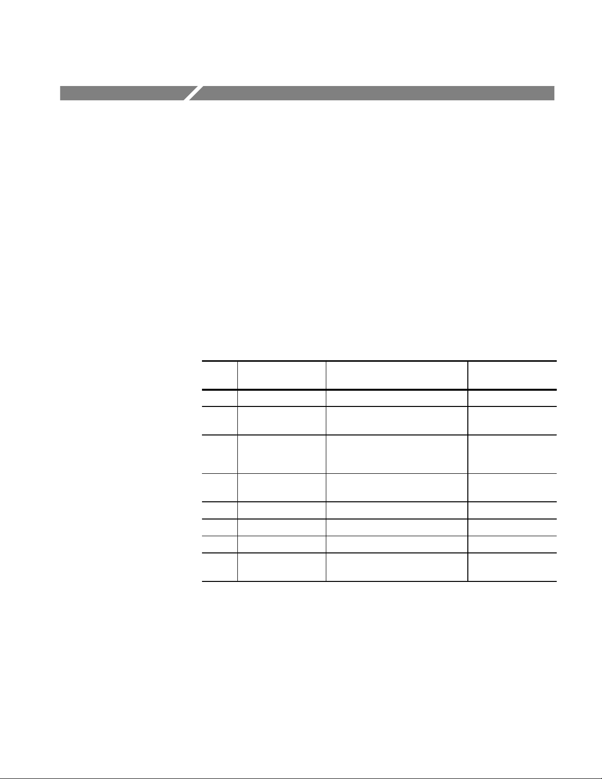
A6304XL Performance Verification
The test procedures in this section check for proper performance of the A6304XL
current probe.
Read page 23 before starting these procedures. Also, read each procedure
through completely before starting to ensure proper completion.
Required Test Equipment
To perform the acceptance tests in this section, you will need the test equipment
listed in Table 30. The test equipment must meet or exceed the specifications
listed. The test procedures may need to be modified if the recommended
equipment is not used.
T able 30: Required Test Equipment
Qty Item Description
1 Oscilloscope 20 MHz bandwidth Tektronix TDS 520B
Recommended
Equipment
1 Digital Multimeter 0.25%, 31/2 digit resolution
at ± 50 mV
1 Current Source 0.3% accuracy, 0 to ±2 A Fluke 5700A or
1 Calibration Generator Square wave with a rise time <35 ns,
5 A into 50
1 Current Loop 250 turns 067-0240-00
1 Termination 50 ±0.1%, 0.5 W 01 1-0129-00
2 BNC Cable 50 , 1.05m (42in) long 012-0057-01
3 BNC to Dual
Banana Adapter
1
AVTECH Electrosystems Ltd.
P.O. Box 265, Ogdensburg NY 13669-0265
(315) 472-5270 or (800) 265-6681
DM2510/G or
Fluke 850x/884x
Wavetek 9100 with
Option 250
AVTECH1
AVR-3-PW-C-P-TEK2
103-0090-00
AM 503B, AM 5030, and A6300 Series Verification and Adjustment
55
Page 66

A6304XL Performance Verification
Rise Time
This procedure measures the rise time of the A6304XL. In this test you directly
measure the rise time of a step input. Refer to Figure 18 when making equipment
connections.
Equipment Connections
Test Oscilloscope
50 W Input
Amplifier in TM
Series Power
Module
Current
Probe
Calibration
Generator
Output Loop
Figure 18: Rise Time Test Setup for the A6304XL
1. Using a BNC cable, connect the Amplifier OUTPUT to a 50 oscilloscope
input. If the input impedance of your oscilloscope is 1 M, connect a 50
feedthrough termination at the oscilloscope input. Do not connect the
termination at the Amplifier output.
2. Connect the probe to the Amplifier.
3. Connect the current loop calibration fixture to the calibration generator 50
fast rise output.
56
NOTE. If your oscilloscope cannot trigger on the pulse, use another BNC cable
to connect the trigger output of the pulse generator to the trigger input of the
oscilloscope. Configure the oscilloscope for an external trigger.
AM 503B, AM 5030, and A6300 Series Verification and Adjustment
Page 67

A6304XL Performance Verification
Equipment Settings
Make or check the equipment settings in Table 31:
T able 31: Equipment Settings for Rise Time
Oscilloscope
Vertical input impedance 50 W
Vertical gain 10 mV/division
Time base 50 ns/division
Record length 500
Coupling DC
Offset 0 V (mid-scale)
Trigger type Edge
Trigger mode Auto
Trigger position 50%
Acquisition mode Average
Number of waveforms to average 8
Measurement type Rise Time
Calibration Generator
Pulse width 250 ms
Pulse repetition frequency 25 Hz
Amplitude 5 A peak
AM 503B and AM 5030
Coupling DC
BW Limit Off
Current/division 1 A/division
Procedure
1. Do not clamp the current probe around any conductor, but make sure the
jaws are locked shut.
2. Press the Amplifier PROBE DEGAUSS AUTOBALANCE button. Wait
for the degauss/autobalance routine to complete before proceeding. The
routine is complete when the indicator light turns off.
3. Clamp the current probe around the current loop calibration fixture. Check
that the arrow-shaped indicator on the probe points away from the source.
4. Using the measurement capability of the oscilloscope, measure the rise time
of the displayed pulse from 10% to 90% amplitude.
5. Check that the rise time is less than the warranted specification. Refer to
Table 11 on page 24.
AM 503B, AM 5030, and A6300 Series Verification and Adjustment
57
Page 68

A6304XL Performance Verification
Bandwidth
The bandwidth of the probe is derived as a function of its rise time. The rise time
(t
edge of the pulse. (Refer to the procedure on page 56.) To calculate the probe
bandwidth, use the following formula:
For example, a rise time of 175 ns would result in the following solution:
) is measured in nanoseconds between the 10% and 90% points of the leading
r
0.35
ǒ
Ǔ
+ Bandwi dth
t
r
DC Gain Accuracy
Equipment Connections
ǒ
175 10
WARNING. This test produces intense magnetic fields that may cause malfunctions in a normally operating heart pacemaker or damage sensitive equipment.
Personnel fitted with pacemakers should not perform this test, and should stay at
least 10 feet from the current loop while the test is being conducted.
This procedure tests the DC gain accuracy of the A6304XL. In this test you
compare the voltage output of the Amplifier to a reference input.
1. Using a BNC cable, connect the Amplifier OUTPUT to a 50 feedthrough
termination. Attach the termination to a BNC-to-dual banana adapter. Taking
care to observe the adapter polarity, insert the dual banana adapter into the
digital multimeter DC voltage input.
2. Connect the current loop to the current source as shown in Figure 19.
0.35
*9
seconds
Ǔ
+ 2.0 106 Hertz
58
AM 503B, AM 5030, and A6300 Series Verification and Adjustment
Page 69

DMM
Amplifier in TM
Series Power
Module
A6304XL Performance Verification
Current
Source
Equipment Settings
+–
250 Turns
BNC to Dual
Banana Adapter
50 Termination
50 Coaxial
Cable
Probe
Figure 19: DC Gain Accuracy Test Setup for the A6304XL
Make or check the equipment settings in Table 32.
T able 32: Equipment Settings for DC Gain Accuracy
Digital Multimeter
Measurement DC volts
Current Source
Output Off
AM 503B and AM 5030
Coupling DC
BW Limit On
Current/division 500 mA/division
Probe trim 000
Output
Sense
Current Flow
+–
WARNING. This test produces intense magnetic fields that may cause malfunctions in a normally operating heart pacemaker or damage sensitive equipment.
Personnel fitted with pacemakers should not perform this test, and should stay at
least 10 feet from the current loop while the test is being conducted.
Procedure
1. Do not clamp the current probe around any conductor, but make sure the
jaws are locked shut.
2. Press the Amplifier PROBE DEGAUSS AUTOBALANCE button. Wait
for the degauss/autobalance routine to complete before proceeding. The
routine is complete when the indicator light turns off.
AM 503B, AM 5030, and A6300 Series Verification and Adjustment
59
Page 70

A6304XL Performance Verification
3. Clamp the current probe around the current loop. Check that the arrow-
4. For each of the Amplifier current/division settings in Table 33 on page 61,
shaped indicator on the probe points away from the current source. (See
Figure 19 on page 59.)
perform the following steps:5
a. Set the Amplifier to the desired current/division setting from Table 33.
b. Set the current source to the correct positive test current using Table 33.
c. Turn on the current source.
d. Record the exact measurement of the digital multimeter as M
. (You can
1
copy Table 34 on page 62 to record the results of your measurements.)
e. Set the current source for the correct negative test current using Table 33.
f. Record the digital multimeter reading as M
g. Calculate the measured current (I
I
m
M1–M
2
(currentdivision)
0.01
) using the following formula:
m
.
2
For example, you might have obtained values of 50 mV for M1 and
48 mV for M
can compute I
(50.0x10
I
m
. If you are using an Amplifier setting of 1 A/division, you
2
as:
m
–3
) – (–48x10–3)
0.01
1 9.80 A
h. Verify that the measured current (Im) is within ±3% of the test current (It)
by computing %Error as follows:
%Error
Im–I
I
t
t
100
For example, using a test current It of 10 A and a measured current Im of
9.80 A, the %Error would be:
60
%Error
9.80 – 10.0
10.0
100 –2%
AM 503B, AM 5030, and A6300 Series Verification and Adjustment
Page 71

A6304XL Performance Verification
T able 33: DC Gain Accuracy Test for
Turns of Current
Loop Passing
Through Probe
250 500mA ±10mA 5A
250 1A ±20 mA 10 A
250 2A ±40 mA 20 A
250 5A ±100 mA 50 A
250 10A ±200mA 100A
250 20A ±400mA 200A
250 50A ±1A 500A
250 100A ±2A 1000 A
250 200A ±2A 1000 A
AM 503B and
AM 5030
Current/Division
the A6304XL
Current Source
Output
Test Current
I
t
AM 503B, AM 5030, and A6300 Series Verification and Adjustment
61
Page 72

A6304XL Performance Verification
T able 34: DC Gain Accuracy Test Work Sheet for the A6304XL
Turns of Current
Loop Passing
Through Probe
AM 503B and
AM 5030
Current/Division
Current Source
Output
Test Current
I
t
250 500 mA ±10 mA 5A
250 1A ±20 mA 10A
250 2A ±40 mA 20A
250 5A ±100 mA 50 A
250 10 A ±200 mA 100A
250 20 A ±400 mA 200A
250 50 A ±1A 500 A
250 100 A ±2A 1000A
250 200 A ±2A 1000A
Note A
Note B
M1–M
+
I
m
0.01
%Error +
2
(currentńdivision)
I
* I
m
t
100
I
t
I
m
M
1
M
2
(Note A)
%Error
(Note B)
62
AM 503B, AM 5030, and A6300 Series Verification and Adjustment
Page 73

Adjustment Procedures for Current Probes
Before performing the adjustment procedures, perform the following steps:
1. Install all plug-in units into the power modules.
2. Attach the current probe to be adjusted.
3. Turn the power on and allow the entire system to warm up for a minimum of
20 minutes. Also warm up any other test equipment used.
AM 503B, AM 5030, and A6300 Series Verification and Adjustment
63
Page 74

Adjustment Procedures for Current Probes
64
AM 503B, AM 5030, and A6300 Series Verification and Adjustment
Page 75

A6312, A6302 and A6302XL Adjustment
The following adjustment procedure describes how to adjust the DC offset of the
A6312, A6302 and A6302XL. Tolerances that are specified in these procedures
apply to the current probes and do not include test equipment error.
Required Test Equipment
To perform the adjustment procedure in this section, you will need the test
equipment listed in Table 35. The test equipment must meet or exceed the
specifications listed. The test procedure may need to be changed if the recommended equipment is not used.
T able 35: Required Test Equipment
Qty Item Description
1 Oscilloscope 150 MHz bandwidth TDS 520B
1 Current Probe Amplifier AM 503B or AM 5030
1 Termination 50 W, BNC connector,
feedthrough
1 BNC Cable 50W , 1.05m (42in) long 012-0057-01
Recommended
Equipment
01 1-0129-00
A6312, A6302 and A6302XL DC Offset Adjustment
Figure 20 shows the location of the DC offset adjustment in the lower probe half.
DC Offset
Figure 20: A6312, A6302 and A6302XL DC Offset Adjustment Location
Equipment Connections
AM 503B, AM 5030, and A6300 Series Verification and Adjustment
1. Connect the Amplifier OUTPUT to a 50 oscilloscope input using a 50
BNC cable. If the input impedance of your oscilloscope is 1 M, connect a
50 feedthrough termination to the oscilloscope input. Do not connect the
termination at the Amplifier output.
2. Connect the current probe to the Amplifier INPUT connector.
65
Page 76

A6312, A6302 and A6302XL Adjustment
3. Do not clamp the current probe around any conductor, but make sure the
jaws are locked shut.
Equipment Settings
Procedure
Make or verify the equipment settings in Table 36:
T able 36: Settings for DC Offset Adjustment
AM 503B and AM 5030
Coupling DC
BW Limit On (20 MHz bandwidth limit)
Current/division 10 mA/division
Oscilloscope
Vertical Gain 10 mV/division
Time Base 1 ms/division,
Auto triggered
Input Coupling Ground
1. Move the oscilloscope trace to the center horizontal graticule line using the
vertical position control.
2. Set the oscilloscope input coupling to DC.
3. Do not clamp the current probe around any conductor, but make sure the
jaws are locked shut.
4. Press the Amplifier PROBE DEGAUSS AUTOBALANCE button. Wait
for the degauss/autobalance routine to complete before proceeding. The
routine is complete when the indicator light turns off.
NOTE. The Amplifier front panel will display error code 266 after the degauss/
autobalance routine completes if the Amplifier is not properly terminated into
50 . Verify that the oscilloscope input is 50 and set to DC coupling. If
necessary, use a 50 termination at the oscilloscope input.
5. If no error codes are displayed after the degauss/autobalance routine
completes, no offset adjustment is necessary. If any of the error codes listed
in Table 37 are displayed, continue with the procedure.
T able 37: Error Codes Requiring DC Offset Adjustment
Error Code Meaning
580 Unable to complete negative offset adjustment
581 Unable to complete positive offset adjustment
66
AM 503B, AM 5030, and A6300 Series Verification and Adjustment
Page 77

A6312, A6302 and A6302XL Adjustment
6. Press and hold the
PROBE DEGAUSS AUTOBALANCE button. This sets the front panel
20 MHz BW LIMIT button, and while holding it, press the
display to –00 and puts the AM 503B and AM 5030 into an internal test
mode.
7. Press the CURRENT/DIVISION
button until the front panel display
reads –52.
8. Press and release the 20 MHz BW LIMIT button. The Amplifier will
degauss itself; wait until the DEGAUSS light goes out.
9. Adjust the DC Offset control so that the oscilloscope trace is on the center
graticule line (zero offset), ±1 division.
10. Press and release the 20 MHz BW LIMIT button, then press and release the
COUPLING button. This exits the AM 503B and AM 5030 test mode.
AM 503B, AM 5030, and A6300 Series Verification and Adjustment
67
Page 78

A6312, A6302 and A6302XL Adjustment
68
AM 503B, AM 5030, and A6300 Series Verification and Adjustment
Page 79

A6303 and A6303XL Adjustments
Each of the following adjustment procedures describes how to adjust specific
performance characteristics of the A6303 and the A6303XL. Tolerances that are
specified in these procedures apply to the current probes and do not include test
equipment error.
Required Test Equipment
To perform the adjustment procedures in this section, you will need the test
equipment listed in Table 38. The test equipment must meet or exceed the
specifications listed. The test procedures may need to be changed if the
recommended equipment is not used.
T able 38: Required Test Equipment
Qty Item Description
1 Oscilloscope 150 MHz bandwidth TDS 520B
1 Current Probe Amplifier AM 503B or AM 5030
1 Calibration Generator DC or 1 kHz square wave,
1 Current Loop 50W 015-0601-50
1 Termination 50 W, BNC connector,
2 BNC Cables 50W, 1.05 m (42in) long 012-0057-01
1 BNC T-adapter 50W 103-0030-00
5V
into 50 W,
p-p
0.5% vertical accuracy
feedthrough
Recommended
Equipment
PG 506A
01 1-0129-00
AM 503B, AM 5030, and A6300 Series Verification and Adjustment
69
Page 80

A6303 and A6303XL Adjustments
A6303 and A6303XL DC Offset Adjustment
This procedure describes how to adjust the DC offset of the A6303 and
A6303XL using the DC Offset adjustment. Refer to Figure 21 when performing
this procedure.
HF2
DC Offset
Equipment Connections
HF3
HF1
A6303 or A6303XL
Current Probe
Figure 21: A6303 and A6303XL Adjustment Locations
1. Connect the Amplifier OUTPUT to a 50 oscilloscope input using a 50
BNC cable. If the input impedance of your oscilloscope is 1 M, connect a
50 feedthrough termination to the oscilloscope input. Do not connect the
termination at the Amplifier output.
2. Connect the current probe to the Amplifier INPUT connector.
3. Do not clamp the current probe around any conductor, but make sure the
jaws are locked shut.
70
AM 503B, AM 5030, and A6300 Series Verification and Adjustment
Page 81

A6303 and A6303XL Adjustments
Equipment Settings
Procedure
Make or verify the equipment settings in Table 39:
T able 39: Settings for DC Offset Adjustment
AM 503B and AM 5030
Coupling DC
BW Limit Off (full bandwidth)
Current/division 10 mA/division
Oscilloscope
Vertical Gain 10 mV/division
Time Base 1 ms/division,
Auto triggered
Input Coupling Ground
1. Move the oscilloscope trace to the center horizontal graticule line using the
vertical position control.
2. Change the oscilloscope input coupling to DC.
3. Do not clamp the current probe around any conductor, but make sure the
jaws are locked shut.
4. Press the Amplifier PROBE DEGAUSS AUTOBALANCE button. Wait
for the degauss/autobalance routine to complete before proceeding. The
routine is complete when the indicator light turns off.
NOTE. The Amplifier front panel will display error code 266 after the degauss/
autobalance routine completes if the Amplifier is not properly terminated into
50 . Verify that the oscilloscope input is 50 and set to DC coupling. If
necessary, use a 50 termination at the oscilloscope input.
5. If no error codes are displayed after the degauss/autobalance routine
completes, no offset adjustment is necessary. If any of the error codes listed
in Table 40 are displayed, continue with the procedure.
T able 40: Error Codes Requiring DC Offset Adjustment
Error Code Meaning
580 Unable to complete negative offset adjustment
581 Unable to complete positive offset adjustment
6. Remove the probe access plug for the DC Offset adjust (see Figure 21).
AM 503B, AM 5030, and A6300 Series Verification and Adjustment
71
Page 82

A6303 and A6303XL Adjustments
7. Press and hold the
PROBE DEGAUSS AUTOBALANCE button. This sets the front panel
display to –00 and puts the AM 503B and AM 5030 into an internal test
mode.
8. Press the CURRENT/DIVISION
reads –52.
9. Press and release the 20 MHz BW LIMIT button. The Amplifier will
degauss itself; wait until the DEGAUSS light goes out.
10. Adjust the DC Offset control so that the oscilloscope trace is on the center
graticule line (zero offset), ±1 division.
11. Press and release the 20MHz BW LIMIT button, then press and release the
COUPLING button. This exits the AM 503B and AM 5030 test mode.
20 MHz BW LIMIT button, and while holding it, press the
button until the front panel display
A6303 and A6303XL Transient Response and Gain Adjustment
This procedure describes how to optimize the transient response and gain of the
A6303 and A6303XL using adjustments HF1, HF2, and HF3. Refer to figures 21
and 22 when performing this procedure.
Equipment Connections
NOTE. The A6303XL has only a single adjustment located at the HF2 position.
1. Connect the calibration generator output to a 50 oscilloscope input using a
50 BNC cable. If the input impedance of your oscilloscope is 1 M,
connect a 50 feedthrough termination to the oscilloscope input. Do not
connect the termination to the calibration generator output.
2. Connect the current probe to the Amplifier INPUT connector.
72
AM 503B, AM 5030, and A6300 Series Verification and Adjustment
Page 83

A6303 and A6303XL Adjustments
Equipment Settings
Amplifier in TM
T est Oscilloscope
50 W Input
Series Power
Module
Figure 22: A6303 and A6303XL Adjustment Setup
Make or verify the equipment settings in Table 41:
Calibration
Generator
High
Amplitude
Output
Current Loop
A6303/A6303XL Probe
Procedure
T able 41: Settings for Transient Response and Gain Adjustments
AM 503B and AM 5030
Coupling DC
BW Limit Off (full bandwidth)
Current/division 20 mA/division
Oscilloscope
Vertical Gain 1 V/division
Time Base 100 ms/division,
Auto triggered
Input Coupling Ground
Calibration Generator
Period 0.1 ms
Function High amplitude
1. Move the oscilloscope trace up one graticule line from the bottom of the
screen.
2. Change the oscilloscope input coupling to DC.
3. Do not clamp the current probe around any conductor, but make sure the
jaws are locked shut.
AM 503B, AM 5030, and A6300 Series Verification and Adjustment
73
Page 84

A6303 and A6303XL Adjustments
4. Press the Amplifier PROBE DEGAUSS AUTOBALANCE button. Wait
NOTE. The Amplifier front panel will display error code 266 after the degauss/
autobalance routine completes if the Amplifier is not properly terminated into
50 . Verify that the oscilloscope input is 50 and set to DC coupling. If
necessary, use a 50 termination at the oscilloscope input.
5. Adjust the calibration generator to produce an amplitude of five graticule
NOTE. Do not adjust the calibration generator amplitude for the remainder of
this procedure.
6. Disconnect the BNC cable from the calibration generator and attach it to the
for the degauss/autobalance routine to complete before proceeding. The
routine is complete when the indicator light turns off.
divisions (5 volts).
Amplifier OUTPUT connector (see Figure 22 on page 73).
7. Attach the current loop to the probe and lock the probe.
8. Connect the current loop to the calibration generator output using another
coaxial cable.
9. Reset the vertical gain of the oscilloscope to 10 mV/division and the time
base to 100 ms/division.
10. Reset the period of the calibration generator to 1 ms.
11. Remove the probe access plugs for HF1, HF2, and HF3. Remove the HF2
plug only for the A6303 (see Figure 21 on page 70).
12. Adjust the probe for optimum performance:
H A6303: Adjust HF1, HF2, and HF3 for an oscilloscope display of five
divisions and optimum transient response.
H A6303XL: Adjust only HF2 for an oscilloscope display of five divisions and
optimum transient response. The A6303XL does not have controls in the
HF1 and HF3 positions.
NOTE. The HF1, HF2, and HF3 adjustments on the A6303 interact. Adjusting
them can be a repetitive process. You may need to balance between transient
response and gain in order to meet both specifications at once.
74
AM 503B, AM 5030, and A6300 Series Verification and Adjustment
Page 85

A6304XL Adjustments
Each of the following adjustment procedures describes how to adjust specific
performance characteristics of the A6304XL. Tolerances that are specified in
these procedures apply to the current probe and do not include test equipment
error.
Required Test Equipment
To perform the adjustment procedures in this section, you will need the test
equipment listed in Table 42. The test equipment must meet or exceed the
specifications listed. The test procedures may need to be changed if Tektronix
equipment is not used.
Perform the steps on page 63 before starting these procedures. Also, read each
procedure through completely before starting to ensure proper completion.
T able 42: Required Test Equipment
Qty Item Description
1 Oscilloscope 20 MHz bandwidth Tektronix TDS 520B
Recommended
Example
1 Current Probe
Amplifier
1 Calibration Generator Square wave with a rise time <35 ns,
5 A into 50
1 Digital Multimeter 0.25% 31/2 digit resolution
at ± 50 mV
1 Current Source 0.3% accuracy, 0 to ±2 A Fluke 5700A or
1 Current Loop 250 turns 067-0240-00
1 Termination 50 ±0.1%, 0.5 W 01 1-0129-00
3 BNC Cables 50 , 1.05m (42in) long 012-0057-01
1 BNC to Dual
Banana Adapter
1
AVTECH Electrosystems Ltd.
P.O. Box 265, Ogdensburg NY 13669-0265
(315) 472-5270 or (800) 265-6681
AM 503B or AM 5030
AVTECH
AVR-3-PW-C-P-TEK2
DM2510/G or
Fluke 850x/884x
Wavetek 9100 with
Option 250
103-0090-00
1
AM 503B, AM 5030, and A6300 Series Verification and Adjustment
75
Page 86

A6304XL Adjustments
A6304XL DC Offset Adjustment
This procedure details how to adjust the A6304XL offset.
Equipment Connections
Equipment Settings
1. Connect the Amplifier OUTPUT to a 50 oscilloscope input using a 50
BNC cable. If the input impedance of your oscilloscope is 1 M, connect a
50 feedthrough termination to the oscilloscope input. Do not connect the
termination at the Amplifier output.
2. Connect the current probe to the Amplifier INPUT connector.
3. Do not clamp the current probe around any conductor, but make sure the
jaws are locked shut.
Make or verify the equipment settings in Table 43:
T able 43: Settings for DC Offset Adjustment
AM 503B and AM 5030
Coupling DC
BW Limit Off (full bandwidth)
Current/division 1 A/division
Oscilloscope
Vertical Gain 10 mV/division
Time Base 1 ms/division,
Auto triggered
Input Coupling Ground
76
Procedure
1. Move the oscilloscope trace to the center horizontal graticule line using the
vertical position control.
2. Change the oscilloscope input coupling to DC.
3. Do not clamp the current probe around any conductor, but make sure the
jaws are locked shut.
4. Press the Amplifier PROBE DEGAUSS AUTOBALANCE button. Wait
for the degauss/autobalance routine to complete before proceeding. The
routine is complete when the indicator light turns off.
NOTE. The Amplifier front panel will display error code 266 after the degauss/
autobalance routine completes if the Amplifier is not properly terminated into
50 . Verify that the oscilloscope input is 50 and set to DC coupling. If
necessary, use a 50 termination at the oscilloscope input.
AM 503B, AM 5030, and A6300 Series Verification and Adjustment
Page 87
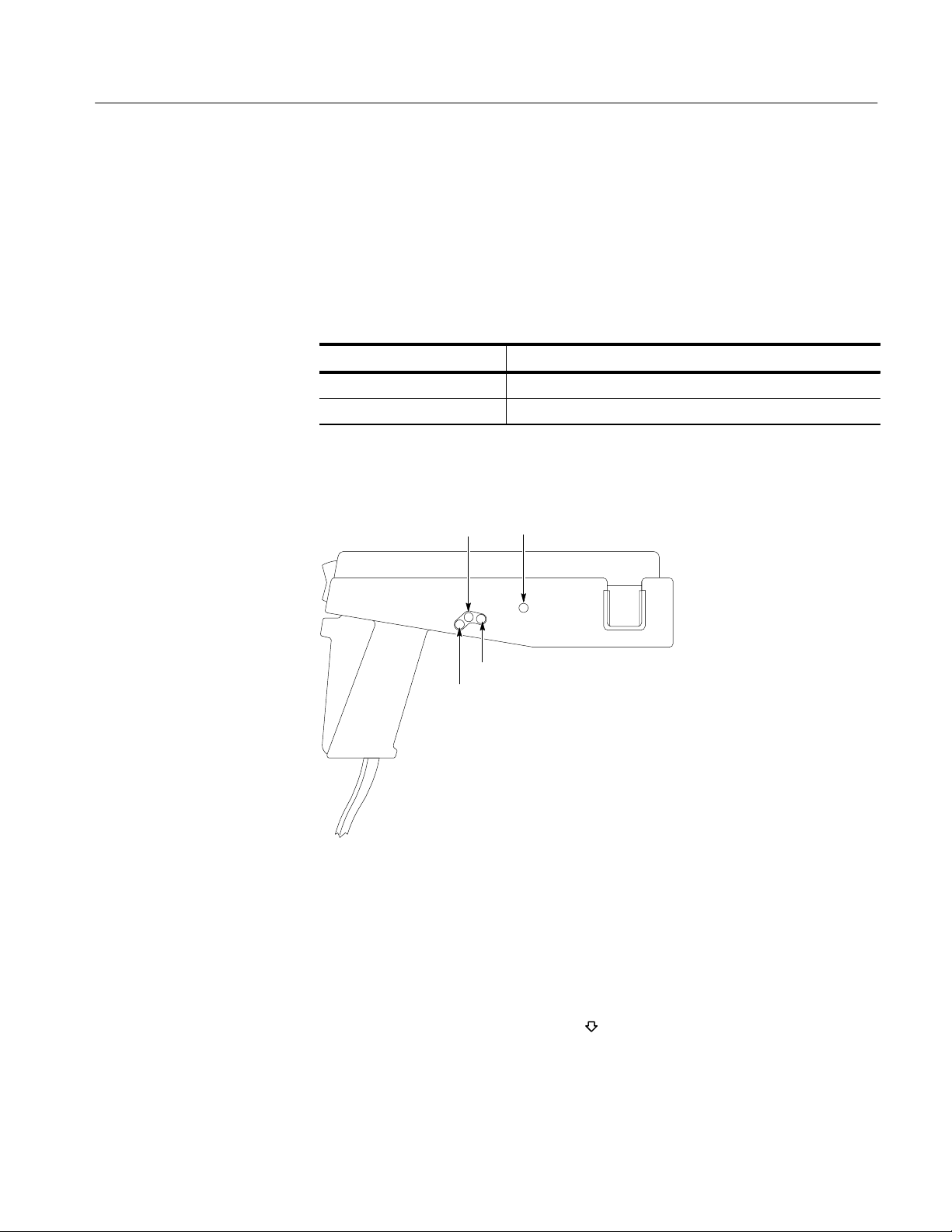
A6304XL Adjustments
5. If no error codes are displayed after the degauss/autobalance routine
completes, no offset adjustment is necessary. Go to the DC Gain Adjustment
on page 78.
6. If either of the error codes in Table 44 are displayed, continue with this
procedure.
T able 44: Error Codes Requiring DC Offset Adjustment
Error Code Meaning
580 Unable to complete negative offset adjustment
581 Unable to complete positive offset adjustment
7. Remove the probe access plug for the DC Offset adjust (see Figure 23).
DC Offset
10 s
DC Gain
1 s
A6304XL
Current Probe
Figure 23: A6304XL Adjustment Locations
8. Press and hold the
PROBE DEGAUSS AUTOBALANCE button. This sets the front panel
20 MHz BW LIMIT button, and while holding it, press the
display to –00 and puts the AM 503B and AM 5030 into an internal test
mode.
9. Press the CURRENT/DIVISION
button until the front panel display
reads –52.
10. Press and release the 20 MHz BW LIMIT button. The Amplifier will
degauss the probe; wait until the DEGAUSS light goes out.
AM 503B, AM 5030, and A6300 Series Verification and Adjustment
77
Page 88
A6304XL Adjustments
DC Gain Adjustment
11. Adjust the DC Offset control so that the oscilloscope trace is on the center
graticule line (zero offset), ±1 division.
12. Press and release the 20MHz BW LIMIT button, then press and release the
COUPLING button. This exits the AM 503B and AM 5030 test mode.
This procedure adjusts the DC gain accuracy of the A6304XL probe.
CAUTION. This test produces magnetic fields that may cause a malfunction in
normally operating heart pacemakers or damage sensitive equipment. Personnel
fitted with pacemakers should not perform this test and should stay at least 10
feet from the current loop while the test is being conducted.
Equipment Settings
Equipment Connections
Make or check the equipment settings in Table 45:
T able 45: Equipment Settings for DC Gain Accuracy
Digital Multimeter
Measurement Type DC volts
Current Source
Output Off
AM 503B and AM 5030
Coupling DC
BW Limit On
Current/division 10 A/division
Probe trim 000
1. Using a BNC cable, connect the Amplifier OUTPUT to a 50 feedthrough
termination. Attach the termination to a BNC-to-dual banana adapter. Taking
care to observe the adapter polarity, insert the dual banana adapter into the
digital multimeter DC voltage input.
2. Connect the current loop to the current source as shown in
Figure 24.
78
AM 503B, AM 5030, and A6300 Series Verification and Adjustment
Page 89

DMM
Amplifier in TM
Series Power
Module
A6304XL Adjustments
Current
Source
Procedure
BNC to Dual
Banana Adapter
50 Termination
50 Coaxial
Cable
Output
+–
250 Turns
Probe
Current Flow
+–
Figure 24: DC Gain Accuracy Adjustment Setup
1. Do not clamp the current probe around any conductor, but make sure the
jaws are locked shut.
2. Press the Amplifier PROBE DEGAUSS AUTOBALANCE button. Wait
for the degauss/autobalance routine to complete before proceeding. The
routine is complete when the indicator light turns off.
3. If necessary, adjust DC LEVEL on the amplifier for a zero reading on the
DMM.
4. Clamp the current probe around the current loop. (See Figure 24.) Check that
the arrow-shaped indicator on the probe points away from the current source.
5. Adjust the current output of the power supply to 200 mA.
6. The DMM reading should be 50 mV. If you could not set your current source
to exactly 200 mA, use the formula below:
DMM voltage reading
current source reading 250 turns
10 Amps/divisio n
7. If the reading is not correct, adjust DC GAIN on the A6304XL for a correct
reading on the DMM. See Figure 23 on page 77.
AM 503B, AM 5030, and A6300 Series Verification and Adjustment
10 mV/ div isi on
79
Page 90

A6304XL Adjustments
A6304XL Transient Response Adjustment
This procedure describes how to optimize the transient response of the A6304XL
using the 10 ms and 1 ms adjustments. Refer to figures 23 and 25 when performing this procedure.
Equipment Connections
Equipment Settings
1. Connect the Amplifier output to a 50 W oscilloscope input using a 50 W
BNC cable. If the input impedance of your oscilloscope is 1 MW, connect a
50 W feedthrough termination to the oscilloscope input.
2. Connect the current probe to the Amplifier INPUT connector.
Test Oscilloscope
50 W Input
Amplifier in TM
Series Power
Module
Current
Probe
Calibration
Generator
Output Loop
Figure 25: A6304XL Adjustment Setup
Make or verify the equipment settings in Table 46:
80
T able 46: Equipment Settings for Transient Response
Oscilloscope
Vertical input impedance 50 W
Vertical gain 10 mV/division
Time base 100 ms/division
Record length 500
Coupling DC
Offset 0 V (mid-scale)
Trigger type Edge
Trigger mode Normal
Trigger position 50%
Acquisition mode Average
Number of waveforms to average 8
Measurement type Rise Time
AM 503B, AM 5030, and A6300 Series Verification and Adjustment
Page 91

T able 46: Equipment Settings for Transient Response (Cont.)
Calibration Generator
Pulse Width 250 s
Pulse Repetition Frequency 20 Hz
Pulse Amplitude 5 A peak
AM 503B and AM 5030
Coupling DC
BW Limit Off
Current/division 1 A/division
A6304XL Adjustments
Procedure
1. Move the oscilloscope trace to one graticule line from the bottom of the
screen.
2. Set the oscilloscope input coupling to DC.
3. Do not clamp the current probe around any conductor, but make sure the
jaws are locked shut.
4. Remove the probe access plugs for 1 ms, 10 ms, and DC Gain.
5. Press the Amplifier PROBE DEGAUSS AUTOBALANCE button. Wait
for the degauss/autobalance routine to complete before proceeding. The
routine is complete when the indicator light turns off.
NOTE. The Amplifier front panel will display error code 266 after the degauss/
autobalance routine completes if the Amplifier is not properly terminated into
50 . Verify that the oscilloscope input is 50 and set to DC coupling. If
necessary, use a 50 termination at the oscilloscope input.
6. Lock the jaws of the probe around the calibrator current loop.
7. Adjust the oscilloscope to view the 100 ms portion of the pulse.
8. Adjust the calibration generator to produce an amplitude of five graticule
divisions (5 amps) at the 100 ms portion of the pulse.
NOTE. Do not adjust the calibration generator amplitude for the remainder of
this procedure.
9. Adjust the 10 s control for a flat waveform to match the level at the 100 ms
point.
10. Adjust the oscilloscope sweep to 1 ms/div.
AM 503B, AM 5030, and A6300 Series Verification and Adjustment
81
Page 92

A6304XL Adjustments
11. Adjust the 1 s control to flatten the front end of the pulse.
NOTE. The 10 ms and 1 ms adjustments on the A6304XL interact. Adjusting them
can be a repetitive process. You may need to balance between short and long
term response in order to meet both specifications at once.
12. Disconnect the probe from the calibration generator current loop.
13. Verify the DC Gain Accuracy using the procedure on page 78.
82
AM 503B, AM 5030, and A6300 Series Verification and Adjustment
Page 93

Page 94

 Loading...