


AM
503
CURRENT
PROBE
AMPLIFIER
7
e
I
d
ronbc
INSTRUCTION
MANUAL
Tektronix,
Inc
.
P.O.
Box
500
Beaverton,
Oregon
97077
Serial
Number
COMMITTED
TO
EXCELLENCE
PLEASE
CHECK
FOR
CHANGE
INFORMATION
AT
THE
REAR
OF
THIS
MANUAL
.
AM
503
CURRENT
PROBE
AMPLIFIER
070-2052-01
First
Printing
SEP
1976
Product
Group
75
Revised
DEC
1985
Copyright
`'
1976,
1979
Tektronix,
Inc
.
All
rights
reserved
.
Contents
of this
publication
may
not
be
reproducedinany
form
without
the
written
permission
of
Tektronix,
Inc
.
Products
of
Tektronix,
Inc.and
its
subsidiaries are
covered
byU.S.and
foreign
patents
and/or
pending patents
.
TEKTRONIX,
TEK,
SCOPE-MOBILE,
and
ilk
are
registered
trademarksofTektronix,
Inc.TELEQUIPMENT
isaregistered
trademarkofTektronixU.K
.
Limited
.
PrintedinU
.S .A
.
Specification
and
price
change
privileges
are
reserved
.
INSTRUMENT
SERIAL
NUMBERS
Each
instrument
has
a
serial
number
on a
panel
insert,
tag,
or
stamped
on
the
chassis.The
first
number
or
letter
designates
the
countryofmanufacture.The
last
five
digits
of
the
serial
number
are
assigned
sequentially
and
are
unique
to
each
instrument.Those
manufactured
in
the
United
States
have
six
unique
digits
.
The
country
of
manufacture
is
identifiedasfollows
:
B000000
Tektronix,
Inc.,Beaverton,
Oregon,
USA
100000
Tektronix
Guernsey,
Ltd.,Channel
Islands
200000
Tektronix
United
Kingdom,
Ltd
.,
London
300000
Sony/Tektronix,
Japan
700000
Tektronix
Holland,
NV,
Heerenveen,
The
Netherlands
TABLE
OF
CONTENTS
Page
OPERATOR'S
SAFETY
SUMMARY
. . . . .
. . . . . . . . . . . . . . ...
. . . .
. . . . . . . . . . . . . .
SERVICE
SAFETY
SUMMARY
. . .
. . . . . .
. . . . . . . . . . . . . ... .
. . . .
. . . . . . . . . . . . . .
V
SECTION
1
OPERATING
INSTRUCTIONS
. . . . . . . . .
. . . . . .
. . . . . .
. . . . . . . . . .
1-1
SECTION
2
SPECIFICATION
AND
PERFORMANCE
CHECK
. ... . . . . . . . . . .
. . . .2-1
WARNING
The
remaining
portionofthis
TableofContents
lists
servicing
instructions
that
expose
personneltohazardous
voltages.These
instructions
are
for
qualified
service
personnel
only
.
SECTION
3
ADJUSTMENT
. . . . . .
. . . . . . . . . . . . . . .
. . . . .
. . . . . . . . . . . . . . . .3-1
SECTION
4
MAINTENANCE
. . ...
. . . . . . . . . . . . . . . .
. . . . .
. . . . . . . . . . . . . . .
4-1
SECTION
5
CIRCUIT
DESCRIPTION
. . . . . . . . . . . . . .
. . . . .
. . . . . . . . . . . . . . . .
5-1
SECTION
6
REPLACEABLE
ELECTRICAL
PARTS
. . . ...
. . . .
. . . . . . . . . . . . . . .6-1
SECTION
7
DIAGRAM
AND
CIRCUIT
BOARD
ILLUSTRATION
.
.
. . . . . . . . . .
. . . .7-1
SECTION
8
REPLACEABLE
MECHANICAL
PARTS
AND
EXPLODED
VIEW
. . . . . . .8-1
CHANGE
INFORMATION
AM
503
LIST
OF
ILLUSTRATIONS
Fig
.
No
.
Page
No
.
1-1
Plug-in
installation
and
removal
. . .
. . . . . . . . . . . . . .
. . . . . . .
. . . . . . . . . . . . . .
1-1
1-2
AM
503
controls
and
connectors.. .
. . . . . . . . . . . . . .
.
. . . . .
. . . . . . . . . . . . . .
1-3
2-1
Test
setup
forACDynamic
Range
check..
. . . . . . . . . . .
. . . . .
. . . . . . . . . . . . .
2-7
2-2
Displayoftangentially
measured
noise
. . . .
. . . . . . . . . . . . .
. . . . . . . .
. . . . . . . .2-
8
3-1
Construction
details
for
Special
Adapter
. . . . . .
. . . . . . . . . . . .
.
. . . . ... . . . .
. .
3-3
3-2
Power
supply
test
point
and
adjustment
locations.. .
. . . . . . . . .
. . . . . . . . . .
. . .
3-3
3-3
Gain
and
compensation
adjustment
locations
. . . . . . .
. . . . . . . . . . . . . .
. . . . . . .
3-5
3-4
Exampleofcorrect
compensation
.
. . . . . . . .
. . . . . . . .
. . . . . . . . . . . . . ... .
. .
3-5
4-1
Lubrication
procedure
foratypical
cam
switch
. .
. . . . . . . . .
. . . . . . . . . . . . . . . .
4-2
42
Semiconductor
lead
configurations
. . . . . . . . . . .
. .
. . . . . .
. . . . . . . . . . . . . . . .
4-4
43
Installation
of
lead-end
connectors
. . . . . . . .
. . . . . .
. . . . . . .
. . . . . . . . . . . . . .
47
44
Circuit
board
pin
and
ferrule
assembly
. . . . . . . . . . . . . .
. . . . . .
. .
. . . . . . ... . . .
47
5-1
AM
503and
probe
waveforms
. . . . . . . .
. . . .
. . . . . . . . . .
. . . . . . . . .
. . . . . . . .
5-1

OPERATOR'S
SAFETY
SUMMARY
The
followingtext
containsa
two-part
summary
of
general
safety
precautions
that
must
be
observed
during
all
phasesofoperation,
service,
and
repair of
this
instrument
.
OPERATORS
SAFETY
SUMMARY
The
general
safety
informationinthis
part of
the
summary
is
for
both
operating
and
servicing
personnel.Specific
warnings
and
cautions
will
be
found
throughout
the
manualwhere
they
apply,
but
may
not
appear
in
this
summary
.
In
This
Manual
TERMS
CAUTION
statements
identify
conditionsorpractices
that
could
resultin
damage
to
the
equipment
or
other
property
.
WARNING
statements
identify
conditions
or
practices
that
could
resultinpersonal
injuryorlossoflife
.
As
Marked
on
Equipment
CAUTION
indicatesapersonal
injury
hazard
not im-
mediately
accessible
as
one
reads
the
marking,
or
a
hazardtoproperty
including
the
equipment
itself
.
DANGER
indicates
a
personal
injury
hazard
immediately
accessibleasone
reads
the
marking
.
In
This
Manual
SYMBOLS
A
This
symbol
indicates
where
applicable
cautionary
or
other
information
istobe
found
.
As
Marked
on
Equipment
DANGER
-
High
voltage
.
REVANOV
1979
Power
Source
Protective
ground
(earth)
terminal
.
ATTENTION
-
refertomanual
.
This
productisintendedtooperate
fromapower
source
that
will
not
apply
more
than
250
volts
rms
between
the
supply
conductors
or
between
either
supply
conductor
and
ground.A
protective
ground
connection
bywayofthe
groundingconductor
in
the
power
cordisessential
for
safe
operation
.
Grounding
the
Product
This
productisgrounded
through
the
grounding
conduc-
torofthe
power
cord.To
avoid
electrical
shock,
plug
the
power
cord
intoaproperly
wired
receptacle
before
connecting
to
the
product
inputoroutput
terminals.A
protective
ground
connection
by
way
of
the
grounding
conductor
in
the
power
cordisessential
for
safe
opera-
tion
.
Danger
Arising
From
Loss
of
Ground
Upon
loss of the
protective-ground
connection,
all
accessible
conductive
parts
(including
knobs
and
con-
trols
that
may
appear
to
be
insulating)
can
renderan
electric
shock
.
Use
the
Proper
Power
Cord
Use
only
a power
cord
thatisin
good
condition
.
Use
the
Proper
Fuse
Use
only
the
power
cord
and
connector
specified
for
your
product
.
Refer
cord
and
connector
changes
to qualified
service
personnel
.
To
avoid
fire
hazard,
use
only
the
fuseofcorrect
type,
voltage
rating
and
current
ratingasspecifiedinthe
parts
list
for
your
product
.
Refer
fuse
replacement
to qualified
service
personnel
.

AM
503
Do
Not
Operate
in
Explosive
Atmospheres
To
avoid
explosion,donot operate
this
productinan
explosive
atmosphere
unlessithas
been
specifically
certified
for
such
operation
.
Do
Not
Remove
Covers
or
Panels
To
avoid
personal
injury,donot
remove
the
product
iv
covers
or
panels.Do
not
operate
the
product
without
the
covers
and
panels
properly
installed
.
Do
Not
Operate
Without
Covers
(for
TM
500
plug-
ins
only)
To
avoid
personal
injury,donot
operate
this
product
without covers
or panels
installed
.
Do
not
apply
power
to
the
plug-in
viaaplug-in
extender
.
REVA
NOV
1979
Do
Not
Service
Alone
REVA
NOV
197
9
SERVICING
SAFETY
SUMMARY
FOR
QUALIFIED
SERVICE
PERSONNEL
ONLY
Do
not
perform
internal
service
or
adjustmentofthis
product
unless
another
person
capableofrendering
first
aid
and
resuscitation
is
present
.
Use
Care
When
Servicing
With
Power
On
Dangerous
voltages
existatseveral
pointsinthis
product
.
To
avoid
personal
injury,donot
touch
exposed
connec-
tions
and
components
while
power
is
on
.
Refer
also to
the
preceding
Operators
Safety
Summary
.
AM
503
Disconnect
power
before
removing
protective
panels,
soldering,
or
replacing
components
.
Power
Source
This
product
is
intendedtooperate
fromapower
source
that
will
not
apply
more
than
250
volts
rms
between
the
supply
conductors
or
between
either
supply
conductor
and
ground.A
protective
ground
connectionbywayofthe
grounding conductor
in
the
power
cordisessential
for
safe
operation
.
v
AM
503
2052-9
REV
A
NOV
197
9
All
references
to
the
P6302
probe
also
apply
to the
A6302
probe
.
All
referencestothe
P6303
probe
also
apply
to the
A6303
probe
.
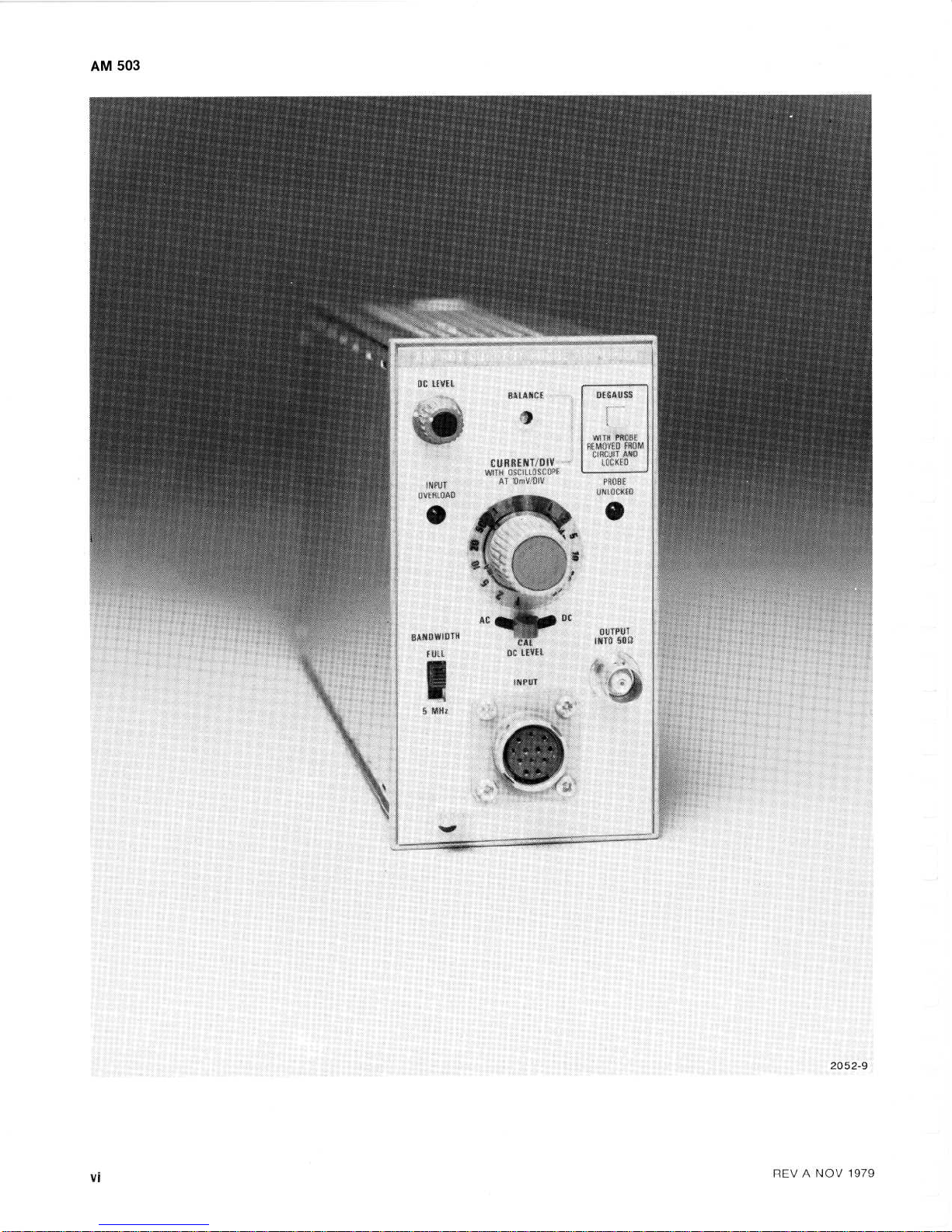
Description
OPERATING
INSTRUCTIONS
NOTE
The
AM
503
Current
Probe
Amplifierisdesigned
for
use
with
any
of
the
compatible
current
probes
(see
Mechanical
Parts
list
for
accessories).The
input
attenuator
is
calibratedina
1, 2,5sequence,
and
the
attenuator
knob-skirt
illumination
provides
direct
indica-
tionofcurrent/division.An
auto-scale
switch
changes
the
knob-skirt
illumination
automatically
to
match
the
sen-
sitivityofthe
probe
used
.
Bandwidth
is
selectable
for
either
FULL
(limited
by
current
probeinuse) or5MHz.Input
couplingisselec-
table
(acordc);ac provides
a
meansofmeasuring
low
amplitude
ac
signalsona high
leveldocurrent
.
Installation
and
Removal
RELEASE
LATCH
PULL
TO
REMOVE
(1431-21)2052-37
REVJUN
198
1
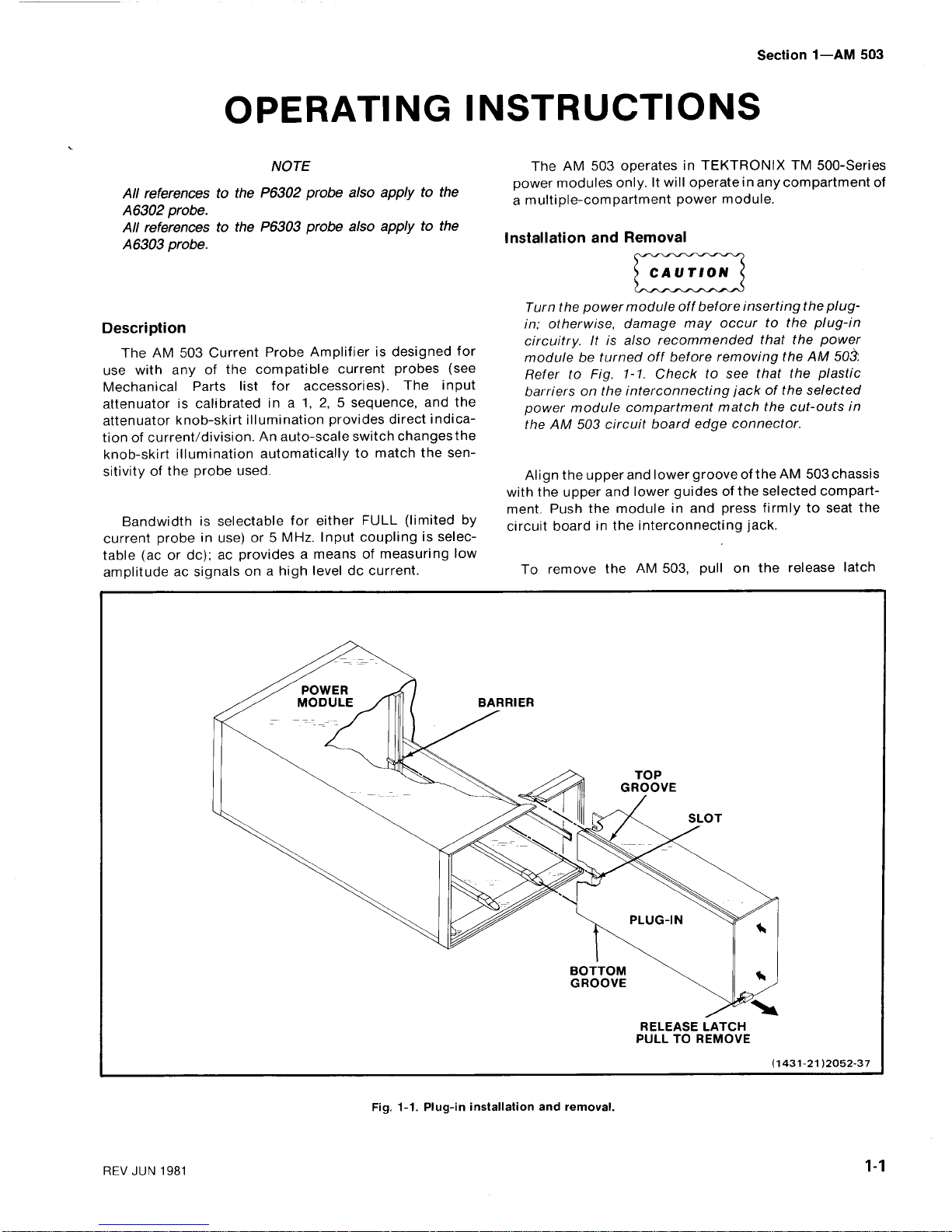
Fig.1-1.Plug-in
installation
and
removal
.
Section
1-AM
503
The
AM
503
operates
in
TEKTRONIX
TM
500-Series
power
modules
only.It
will
operatein
any
compartment
of
a
multiple-compartment
power
module
.
Turn
the
power
module
off
before
inserting
the
plug-
in;otherwise,
damage
may
occur
to the
plug-in
circuitry.Itisalso
recommended
that
the
power
modulebeturned
off
before
removing
the
AM
50,'~
RefertoFig
.
1-1.Check
to
see
that
the
plastic
barriers
on
the
interconnecting
jackofthe
selected
power
module
compartment
match
the
cut-outs
in
theAM503
circuit
board
edge
connector
.
Alignthe
upper
and
lower
grooveoftheAM503
chassis
with
the
upper
and
lower
guidesofthe
selected
compart-
ment.Push
the
module
in
and
press
firmlytoseat
the
circuit
boardinthe
interconnecting
jack
.
To
remove
the
AM
503,
pullonthe
release
latch

Operating
Instructions-AM
503
(locatedinthe lower
left
corner)
until
the
interconnecting
jack
disengages
and
the
AM
503
will
slide
out
.
OPERATING
CONSIDERATIONS
Introduction
The
remainder
of this
section
contains
the
operating
information
required
to
obtain
the
most
effective
perfor-
mance
from
the instrument
.
This
includes
the
function
and
actionsofthe
controls
and
connectors,
input
connec-
tions,
andageneral
descriptionofthe operating
modes
and
procedures
for
making
basic
measurements
.
Controls
and
Connectors
Allofthe
major
controls
and
connectors
for
operation
of
the
AM
503
are
located
on
the
front
panel
of
the
unit.A
brief
functional
descriptionofeach
control
and
connector
is
included
in
Fig.1-2
.
Monitor
Oscilloscope
The
bandwidth
requiredofthe
oscilloscope
used
with
the
AM
503
depends
upon
the
frequencyofthe
signal
being
measured.Oscilloscope
vertical
bandwidth
should
be
at
least
twice
the
frequency
of
the
signal
being
measured
.
Deflection
.
Conventional
current flowing
in
the
direc-
tionofthe
arrow
on
the
current-probe
slider
produces
a
positive
deflectionofthe
oscilloscope
display
.
Ground-clip
Leads
Ground-clip
leads
are furnished
with
some
current
probes
to
ground
the cable
shieldatthe
probe
end
.
The
ground
leadisused
to
reduce
high-frequency
elec-
trostatic
voltages
that
could
couple
into
the
probe
and
cause
errorsinmeasuring
.Aground
lead
is
normally not
usedinthe
lower
(1,
2, 5,
and
10
mA)
sensitivity
positions
of
the
attenuator
switch
becauseofundesirable
chassis
currents
that
may
appear
in
these
more
sensitive
positions
.
When
observing
high-frequency
signals,
use
the
shortest
practical
ground-clip
lead
available
.
Output
Connection
output
connection
can
be
accomplished
through
the
OUTPUT
INTO
50
f2
connectororthe
rear
interconnec-
ting
jackatpin
28A.Pin
28Aatthe
rear
interconnecting
jackisterminated
in50S2.Connector
J480,
located
onthe
right
side
upper-rearofthe
instrument,iswhere
the
output
cable
connects
for
rear
interface
output
.
With
the
output
cable
connected
for
rear
interface
output,
atermination
is
not
required
because
of
the
internal
(factory
wired)
termination.The
monitor
oscilloscope
input
impedance
should not be 50Oif
the
rear
interface
connection
is
used
.
It
will
cause
an
impedance
mis-match
and
possible
loading
of
the
AM
503
.
Changing
output
to rear
interface.Remove
the
right
side
snap-in
cover
from
the
AM
503.Unplug
the
coaxial
cable
from
the
rear of
the
OUTPUT
INTO
50Oconnector
.
Carefully
align
the
coaxial
cableatthe
upper-rear
coaxial
connector;pressing
firmly,
insert
the
cable
.
The
coaxial
cable
connector
center
piniseasily
bent
and
alignment
is
critical
when
making
the
connec-
tion
for
rear
interface
output
.
With the output
cable
(internal)
connectedtothe
rear
interconnecting
jack
output,
the
front-panel
OUTPUT
INTO
50
O
connector
will
not
have
an output
signal
available
.
Connecting
the
AM
503
Install
the
AM
503
into
the
TM
500-Series
power
module
.
Ensure
that
the
power
module
into
which
the
AM
503
willbeinstalled
is
suitably
adapted
to
the
line
voltagetobe
applied
.
Connect
a 500cable
with
bnc
connectors
(and
if
necessary,
a 50
O
termi
nation for
impedance
matching)
to
the
monitor
oscilloscope
vertical
input
.
Set
the
monitor
oscilloscope
vertical
sensitivity
for
10
mV/Div
.
The
horizontal
sweep
speed
should be
consis-
tent
with
the
signal
frequencytobe
examined
.
Connectacurrent
probetothe
AM
5031NPUTconnec-
tor
.
Turn
all
equipment
on
and
allow 20
minutes
for
the
equipmenttowarm
up
and
stabilize
.
REVBNOV
197
9
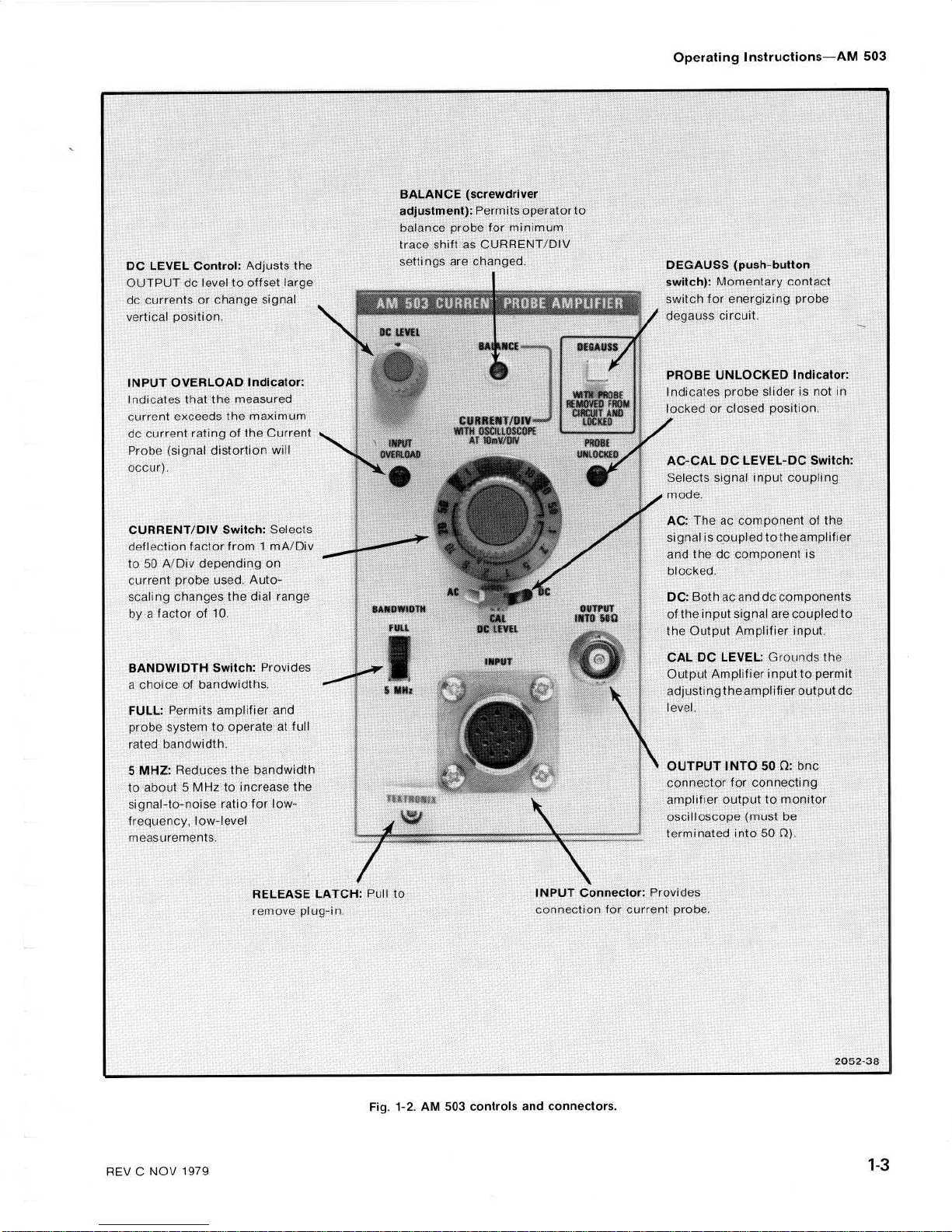
DC
LEVEL
Control:Adjusts
the
OUTPUT
do
leveltooffset
largo
do
currentsorchange
signal
vi
:rti-l
p-tior
INPUT
OVERLOAD
Indicator
:
Indicates
that
the
measured
current
exceeds
the
maximum
do
current
rating of
the
Current
Probe
(signal
distortion
will
occur)
.
CURRENT/DIV
Switch
:
Selects
deflection
factor
from1mA/Div
to
50 A/Div
depending
on
current
probe
used.Auto-
scaling
changes
the
dial
range
by
a
factorof10
.
BANDWIDTH
Switch
:
Provides
a
choiceofbandwidths
.
FULL:Permits
amplifier
and
probe
systemtooperateatfull
rated
bandwidth
.
5
MHZ:Reduces
the
bandwidth
to
about5MHztoincrease
the
signal-to-noise
ratio
for
low-
frequency,
low-level
measurements
.
REV
C
NOV
197
9
F'.;:,tL
,
Y4'tD1H
RELEASE
LATCH
:
Pull
to
t,:dove
plug-in
.
BALANCE
(screwdriver
adjustment):Permits
operritorto
!-Iaiice
probe
for
minimum
tr,p,shiftasCURRENT
DIV
- .tt
;,w,
are
changed
.
Fig.1-2.AM
503
controls
and
connectors
.
INPUT
Connector:Provides
c
m),~,
tion
for
current
probe
.
Operating
Instructions-AM
503
DEGAUSS
(push-button
switch):Momentary
contact
switch
for
energizing
probe
degauss
circuit
.
PROBE
UNLOCKED
Indicator
:
Indicates
probe
sliderisnot
in
locked
or
closed
position
AC-CAL
DC
LEVEL-DC
Switch
:
Selects
signal
input
coupling
mode
.
AC:TheaccomponentoftI
signaliscoupled
tothe
amplifier
and
thedocomponent
is
blocked
.
DC:Both ac
anddocomponents
of
the
input
signal
are
coupled
to
the
Output
Amplifier
input
.
CAL
DC
LEVEL:Grounds
th
Output
Amplifier
inputtopermit
adjusting
the
amplifier
output
do
level
.
OUTPUT
INTO50O
:
bnc
connector
for
connecting
amplifier
outputtomonitor
oscilloscope
(must be
terminated
into50S2)
.
2052-38
Operating
Instructions-AM
503
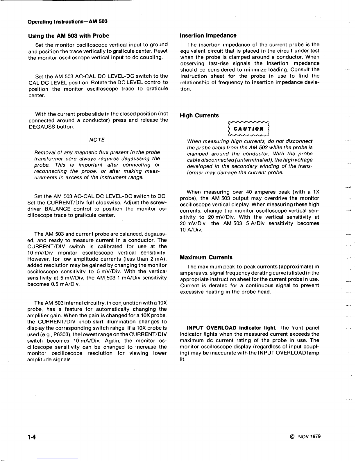
Using
the
AM
503
with
Probe
Set
the
monitor
oscilloscope
vertical
inputtoground
and
position
the
trace
verticallytograticule
center.Reset
the
monitor
oscilloscope
vertical
inputtodo
coupling
.
Set
the
AM
503
AC-CAL
DC
LEVEL-DC
switchtothe
CAL
DC
LEVEL
position.Rotate theDCLEVEL
control
to
position
the
monitor
oscilloscope
trace
to
graticule
center
.
With the
current
probe
slideinthe closed
position
(not
connected aroundaconductor)
press
and
release
the
DEGAUSS
button
.
NOTE
Removalofany
magnetic
flux
presentinthe
probe
transformer core
always
requires
degaussing
the
probe.This
is
important
after
connecting
or
reconnecting
the
probe,
or
after
making
meas-
urementsinexcessofthe instrument
range
.
Set
the
AM
503
AC-CAL
DC
LEVEL-DC
switchtoDC
.
Set
the
CURRENT/DIV
full
clockwise.Adjust
the screw-
driver
BALANCE
controltoposition
the
monitor
os-
cilloscope
tracetograticule
center
.
The
AM
503
and
current
probe
are
balanced,
degauss-
ed,
and
readytomeasure
currentina
conductor.The
CURRENT/DIV
switch
is
calibrated
for
use
at
the
10
mV/Div
monitor
oscilloscope
vertical
sensitivity
.
However,
for
low
amplitude
currents
(less
than
2
mA),
added
resolution
maybegainedbychanging
the
monitor
oscilloscope
sensitivityto5
mV/Div.With
the
vertical
sensitivityat5
mV/Div,
the
AM
5031mA/Div
sensitivity
becomes0.5
mA/Div
.
The
AM
503
internal
circuitry,inconjunction
witha10X
probe,
hasafeature
for
automatically
changing
the
amplifier
gain.When
the
gainischanged
fora10X
probe,
the
CURRENT/DIV
knob-skirt
illumination
changes
to
display
the
corresponding
switch
range.Ifa10X
probe
is
used
(e.g.,
P6303),
the
lowest
rangeonthe
CURRENT/DIV
switch
becomes
10
mA/Div.Again,
the
monitor
os-
cilloscope
sensitivity
can
be
changed
to
increase
the
monitor
oscilloscope
resolution
for
viewing lower
amplitude
signals
.
Insertion
Impedance
The
insertion
impedance
of
the
current
probeisthe
equivalent
circuit
thatisplacedinthe
circuit
under
test
when
the
probeisclamped
aroundaconductor.When
observing
fast-rise
signals
the
insertion
impedance
should
be
consideredtominimize
loading.Consult
the
Instruction
sheet
for
the
probe
in
use
to find
the
relationshipoffrequencytoinsertion
impedance
devia-
tion
.
High
Currents
When
measuring
high
currents,donot
disconnect
the
probe
cable
from
theAM503
while
the
probe
is
clamped
around
the
conductor.With
the
probe
cable
disconnected
(unterminated),
thehigh
voltage
developedinthe
secondary
winding
of the
trans-
former
may
damage
the
current
probe
.
When
measuring
over
40
amperes
peak
(with
a 1X
probe),
the
AM
503
output
may
overdrive
the
monitor
oscilloscope
vertical
display.When
measuring
these
high
currents,
change
the
monitor
oscilloscope
vertical
sen-
sitivityto20
mV/Div.With
the
vertical
sensitivity
at
20
mV/Div,
the
AM
5035A/Div
sensitivity
becomes
10
A/Div
.
Maximum
Currents
The
maximum
peak-to-peak
currents
(approximate)
in
amperesvs.
signal
frequency
derating
curveislistedinthe
appropriate
instruction
sheet
for
the
current
probeinuse
.
Currentisderated
foracontinuous
signal to
prevent
excessive
heatinginthe
probe
head
.
INPUT
OVERLOAD
indicator
light.The
front
panel
indicator
lights
when
the
measured
current
exceeds
the
maximum
do
current
ratingofthe
probe
in
use.The
monitor
oscilloscope
display
(regardless
of
input
coupl-
ing)
may
be
inaccurate
with
the
INPUT
OVERLOAD
lamp
lit
.
@
NOV
1979
SPECIFICATION
AND
PERFORMANCE
CHECK
Performance
Conditions
The
electrical
characteristics
are
valid
onlyifthe
AM
503 has
been
calibratedatan
ambienttemperature
between
+20°Cand
+30'C
and
is
operatingatan
ambient
temperature
between
0°C
and
+50°C,
unless
otherwise
stated
.
REV
SEP
1984
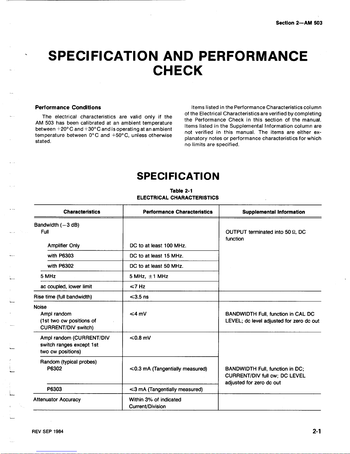
SPECIFICATION
Table
2-1
ELECTRICAL
CHARACTERISTICS
Section
2-AM
503
Items
listedinthe
Performance
Characteristics
column
of
the
Electrical
Characteristics
are
verifiedbycompleting
the
Performance
Check
in
this
sectionofthe
manual
.
Items
listedinthe
Supplemental
Information
column
are
not
verifiedinthis
manual.The
items
are
either
ex-
planatory
notesorperformance
characteristics
for
which
no
limits
are
specified
.
Characteristics
Performance
Characteristics
Supplemental
Information
Bandwidth
(-3
dB)
Full
OUTPUT
terminated
into
5012,
DC
function
Amplifier
Only
DC
to at
least
100
MHz
.
with
P6303
DC
to at
least15MHz
.
with
P6302
DC
to at
least50MHz
.
5
MHz
5
MHz,
±1
MHz
ac
coupled,
lower
limit
-7
Hz
Rise time
(full
bandwidth)
_3.5ns
Noise
Ampl
random
_-4
mV
BANDWIDTH
Full,
functioninCAL
DC
(1
st
twocwpositions
of
LEVEL;do
level
adjusted
for
zerodoout
CURRENT/DIV
switch)
Amplrandom
(CURRENT/DIV
_-0
.8
mV
switch
ranges except
1st
two
cw
positions)
Random
(typical
probes)
P6302
_-0.3mA
(Tangentially
measured)
BANDWIDTH
Full,
functioninDC
;
CURRENT/DIV
fullcw;DCLEVEL
adjusted
for
zerodoout
P6303
<3
mA
(Tangentially
measured)
Attenuator
Accuracy
Within3%of
indicated
Current/Division
Specification
and
Performance
Check-AM
503
2-2
Standard
Instrument
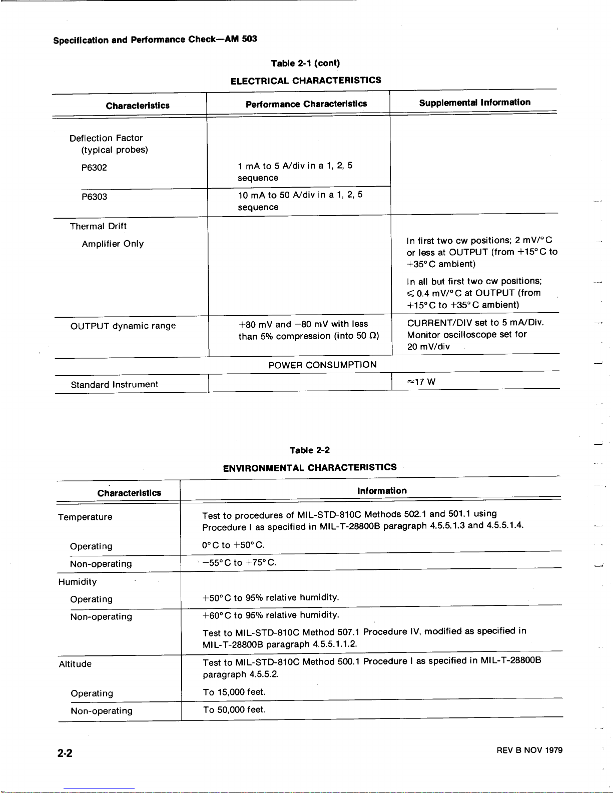
Table
2-1
(cont)
ELECTRICAL
CHARACTERISTICS
POWER
CONSUMPTION
L
Table
2-2
ENVIRONMENTAL
CHARACTERISTICS
--17
W
REVBNOV
1979
Characteristics
Performance
Characteristics
Supplemental
Information
Deflection
Factor
(typical
probes)
P6302
1mAto
5 A/divina
1,
2,
5
sequence
P6303
10
mAto50
A/divina
1, 2,
5
sequence
Thermal
Drift
Amplifier
Only
In
first
two
cw
positions
;
2
mV/°C
or less at
OUTPUT
(from
+15°C
to
+35°C
ambient)
In
all
but
first
two
cw
positions
;
0.4mV/°C
at
OUTPUT
(from
+15
0Cto
+350C
ambient)
OUTPUT
dynamic
range
+80
mV
and
-80
mV
with
less
CURRENT/DIV
setto5
mA/Div
.
than
5%
compression
(into50i2)
Monitor
oscilloscope
set
for
20
mV/div
Characteristics
Information
Temperature
Testtoprocedures
of
MIL-STD-810CMethods
502.1and
501.1using
Procedure
IasspecifiedinMIL-T-2880013
paragraph4.5 .5.1.3
and4.5
.5 .1 .4
.
Operating
0°Cto
+50°C.
Non-operating
-55°Cto
+75°C.
Humidity
Operating
+50°C
to
95%
relative
humidity
.
Non-operating
+60°C
to
95%
relative
humidity
.
TesttoMIL-STD-810C
Method
507.1Procedure
IV,
modified
as
specified
in
MIL-T-2880013
paragraph
4.5.5.1.1.2.
Altitude
TesttoMIL-STD-810C
Method
500.1Procedure
Iasspecified
in
MIL-T-2880013
paragraph
4
.5 .5 .2
.
Operating
To
15,000
feet
.
Non-operating
To
50,000
feet
.
Introduction
This
procedure
checksthe
electrical
characteristics
of
theAM503
that
appearinthe
Specification
sectionofthis
manual.If
the
instrument
failstomeet
the
requirements
given
in this
performance
check, the
adjustment
procedure
shouldbeperformed.This
procedurecan
also
be
used
by an
incoming
inspection
facilitytodetermine
acceptabilityofperformance
.
The
electrical
characteristicsinSection 2arevalid
only
if
the
AM
503iscalibratedatan
ambienttemperature
of
+20'C
to
+30°Cand
operatedatan
ambient
temperature
of
0°Cto
+50'C
.
REVB
NOV
1979
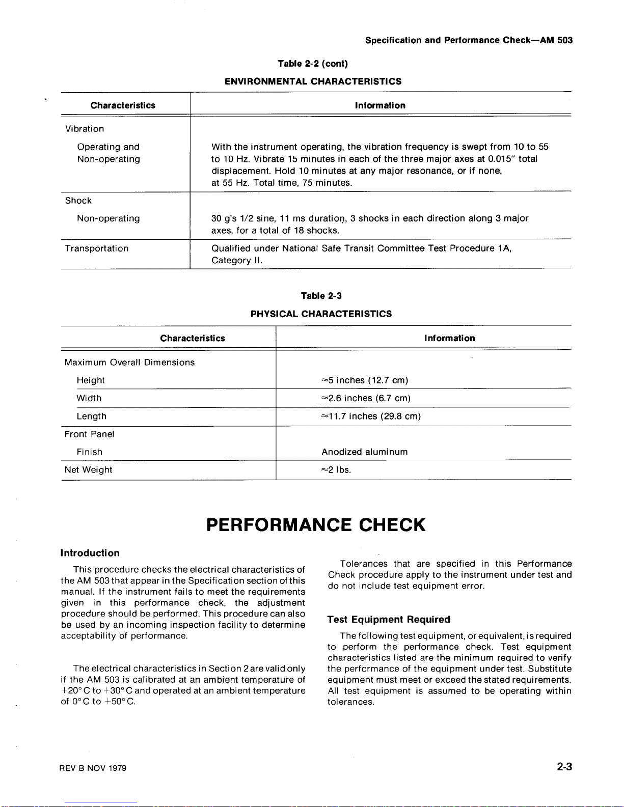
Table
2-2
(cont)
ENVIRONMENTAL
CHARACTERISTICS
Table
2-3
PHYSICAL
CHARACTERISTICS
PERFORMANCE
CHECK
Specification
and
Performance
Check-AM
503
Tolerances
that
are specifiedinthis
Performance
Check
procedure
applytothe instrument
under
test
and
do
not
include
test
equipment
error
.
Test
Equipment
Required
The
following
test
equi
pment,orequivalent,isrequired
to
perform
the
performance
check.Test
equipment
characteristics
listed
are
the
minimum
requiredtoverify
the
performanceofthe
equipment
under
test.Substitute
equipment
mustmeetorexceed
the
stated
requirements
.
All
test
equipment
is
assumed
to
be operating
within
tolerances
.
2-
3
Characteristics
Information
Vibration
Operating
and
With
the instrument
operating,
the
vibration
frequencyisswept
from10to
55
Non-operating
to10Hz.Vibrate15minutesineachofthe
three
major
axesat0
.015"
total
displacement.Hold10minutesatany
major
resonance,orif
none,
at
55 Hz.Total time,75minutes
.
Shock
Non-operating
30
g's
1/2
sine,11ms
duration,3shocksineach
direction
along3major
axes,
foratotalof18
shocks
.
Transportation
Qualified
under
National
Safe
Transit
Committee
Test
Procedure
1A,
CategoryII.
Characteristics
Information
Maximum
Overall
Dimensions
Height
-5
inches
(12.7cm)
Width
=2.6inches
(6 .7
cm)
Length
-11.7inches
(29.8cm)
Front Panel
Finish
Anodized
aluminum
NetWeight
-=2
lbs
.
Specification
and
Performance
Check-AM
503
Special
test
devices are used
where
necessary
to
Tektronix,
Inc.,and
canbeorderedthrough
your
local
facilitate
the
procedure.Most
of
these
are available
from
Tektronix
Field
Officeorrepresentative
.
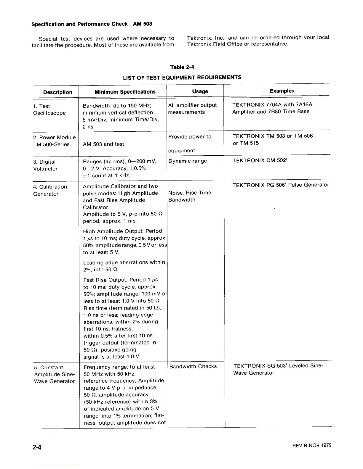
Table
2-4
LIST
OFTEST
EQUIPMENT
REQUIREMENTS
2-
4
REV
B
NOV
1979
Description
Minimum
Specifications
Usage
Examples
1.Test
Bandwidth
:doto
150
MHz
;
All
amplifier
output
TEKTRONIX
7704A
with
7A16A
Oscilloscope
minimum
vertical
deflection
measurements
Amplifier
and
71380
Time
Base
5
mV/Div;minimum
Time/Div,
2ns.
2.Power
Module
Provide
power
to
TEKTRONIX
TM
503
or
TM
506
TM
500-Series
AM
503
and
test
or
TM
515
equipment
3.Digital
Ranges
(ac
rms),
0-200
mV,
Dynamic
range
TEKTRONIX
DM
502'
Voltmeter
0-2
V;Accuracy,±0.5%
±1
countat1
kHz
.
4
.
Calibration
Amplitude
Calibrator
andtwo
TEKTRONIX
PG
506'
Pulse
Generator
Generator
pulse
modes
:
High
Amplitude
Noise
.
Rise
Time
and
Fast
Rise
Amplitude
Bandwidth
Calibrator
.
Amplitude
to
5V,p-p
into50C2
;
period,
approx.1ms.
High
AmplitudeOutput:Period
1
/is
to
10ms;
duty
cycle,
approx
.
50%
;
amplitude
range,0.5Vor less
toatleast5V
.
Leading
edge
aberrations
within
2%,
into50Q
.
Fast
Rise
Output.Period1/is
to10ms;duty
cycle,
approx
.
50%;amplitude
range,
100
mV
or
lesstoat
least
1.0V
into50Q
.
Rise
time
(terminatedin50
S2),
1.0ns
or less;leading
edge
aberrations,
within
2%
during
first
10 ns
;
flatness
within0.5%
after
first10ns
;
trigger
output
(terminated
in
50
O),
positive
going
signal
is
at
least1.0V.
5.Constant
Frequency
range,toat
least
Bandwidth
Checks
TEKTRONIX
SG
503'
Leveled Sine-
Amplitude
Sine- 50
MHz
with
50
kHz
Wave
Generator
Wave
Generator
reference
frequency;Amplitude
rangeto4Vp-p;impedance,
500;
amplitude
accuracy
(50
kHz
reference)
within
3%
of
indicated
amplitudeon5
V
range,
into1%termination;flat-
ness,
output
amplitudedoes
not
8
RequiresTM500-Series
Power
Module
.
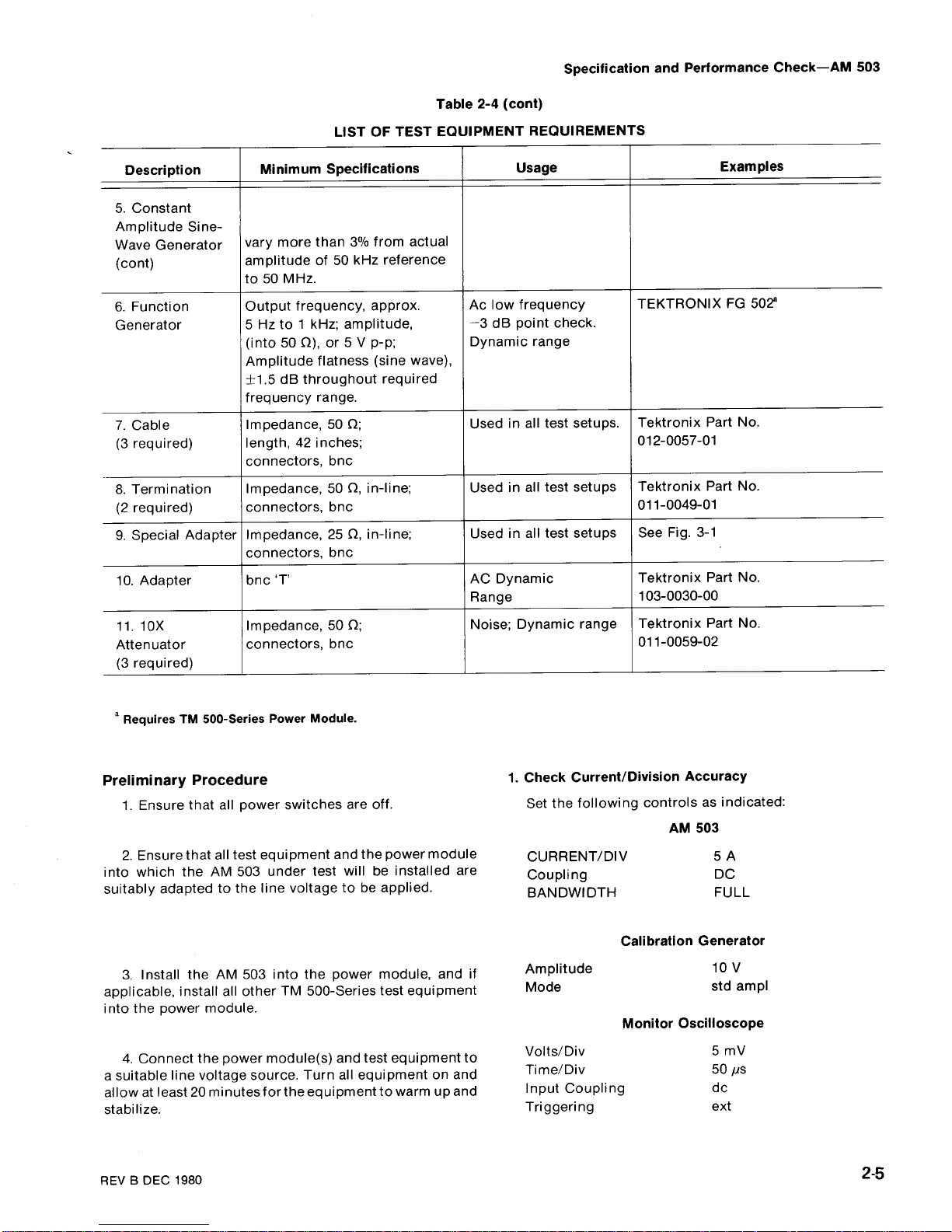
Table
2-4
(cont)
LIST
OF
TEST
EQUIPMENTREQUIREMENTS
Specification
and
Performance
Check-AM
503
Preliminary
Procedure
1.Check
Current/Division
Accuracy
1.Ensure
that
all
power
switches
are
off
.
Set the
following
controlsasindicated
:
2.Ensurethat
all
test
equipment
and
the
power
module
into
which
the
AM
503
under
test
willbeinstalled
are
suitably
adaptedtothe
line
voltagetobe
applied
.
3.Install
the
AM
503
into
the
power
module,
and
if
applicable,
install
all
otherTM500-Series
test
equipment
into
the
power
module
.
4.Connect
the
power
module(s)
and
test
equipment
to
a
suitable
line
voltage
source.Turn
all
equipment
on
and
allowatleast20minutes
for
the
equipmenttowarmupand
stabilize
.
REVBDEC
1980
AM
503
CURRENT/DIV
5
A
Coupling
DC
BANDWIDTH
FULL
Calibration
Generator
Amplitude
lo
v
Mode
std
ampl
Monitor
Oscilloscope
Volts/Div
5
mV
Time/Div
50
/is
Input
Coupling
do
Triggering
ext
2-5
Description
Minimum
Specifications
Usage
Examples
5.Constant
Amplitude
Sine-
Wave
Generator
vary
more
than3%from
actual
(cont)
amplitudeof50
kHz
reference
to50MHz
.
6.Function
Output
frequency,
approx
.
Ac
low
frequency
TEKTRONIX
FG
502
8
Generator
5
Hzto1
kHz;amplitude,
-3
dB
point
check
.
(into50S2),or5Vp-p
;
Dynamic
range
Amplitude
flatness
(sine
wave),
+1.5dB
throughout
required
frequency
range
.
7.Cable
Impedance,
50
f2
;
Usedinall
test
setups
.
Tektronix
PartNo.
(3
required)
length,
42 inches
;
012-0057-01
connectors,
bnc
8.Termination
Impedance,
50
S2,
in-line
;
Usedinall
test
setups Tektronix
PartNo.
(2
required)
connectors,
bnc
011-0049-01
9.Special
Adapter Impedance,
25
S2,
in-line
;
Usedinall
test
setups
See
Fig.3-1
connectors,
bnc
10.Adapter
bnc
`T'
AC
Dynamic
Tektronix
PartNo.
Range
103-0030-00
11.10X
Impedance,
50
O
;
Noise
;
Dynamic
range
Tektronix
PartNo.
Attenuator connectors,
bnc
011-0059-02
(3
required)
Specification
and
Performance
Check-AM
503
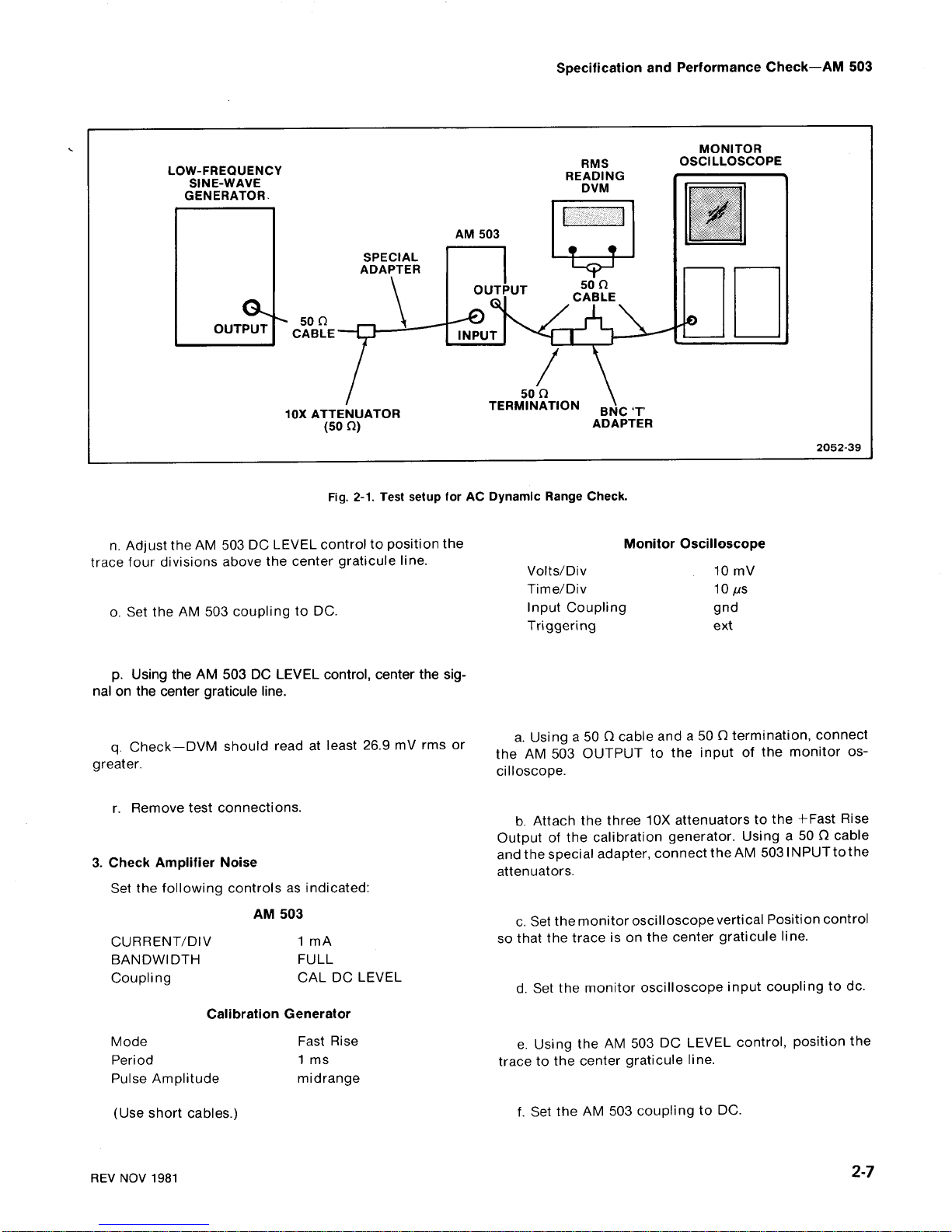
a.Connect
the
OUTPUT
of
the
AM
503tothe
input
of
the
monitor
oscilloscope
using a 500cable
and
a 50
O
terminator
.
b
.
Connect
the
Ampl
Output
of
the
calibration
generatortothe
AM
503
INPUT
using
the
special
adapter
(see
Fig.3-1)
anda500cable
.
c.Using
theAM503DCLEVEL
control
andthe
monitor
oscilloscope
vertical
position
control,
center
the
display
.
e.Set
the
AM
503,
calibration
generator,
and
monitor
oscilloscopeasindicatedinTable
2-2
.
f.Check-that
the
signal
amplitudeineach
step
isfive
divisions±0.15
division
.
2.Check
AC
Dynamic
Range
2-6
d.Check-that
the
signal
amplitudeistwo
divisions
.
Table
2-2
CURRENT/DIVISION
ACCURACY
CONTROL
SETTINGS
g
.Remove
test
connections
.
Set the
following
controls
as
indicated
:
AM
503
CURRENT/DIV
5
mA
Coupling
DC
BANDWIDTH
FULL
Low
FrequencySine-Wave
Generator
Frequency
100
Hz
Amplitude
Minimum
Offset
Off
(in)
Monitor
Oscilloscope
Volts/Div
20
mV
Coupling
do
Time/Div
5
ms
a.See
Fig.2-1
for
test
setup
.
b.Set
the
sine-wavegenerator
for
28.3mV,rms
out
of
theAM503
(monitor
oscilloscope
indicates80mV,
peak-
to-peak)
.
c.Set
monitor
oscilloscope
input
couplingtognd
.
Position
trace
vertically
four
divisions
below
the
center
graticule
line
.
d.Reset
monitor
oscilloscope
input
coupling todc.
e.Set
AM
503
couplingtoCAL
DC
LEVEL
.
f.Adjust
AM
503
DC
LEVELtoposition
trace
vertically
four
divisions
below
the
center
graticule
line
.
g.Reset the
AM
503
coupling toDC.
h.Using
theAM503
DC
LEVEL
control,
center the
sig-
nalonthe center
graticule
line
.
i .
Check-DVM
should
readatleast26.9mVrms
or
greater
.
j .
Set
monitor
oscilloscope
input
couplingtognd
.
k.Position
the
trace
vertically
four
divisions
above
the
center
graticule
line
.
I.Reset the
monitor
oscilloscope
input
couplingtodc
.
m
.
Set
the
AM
503 couplingtoCAL
DC
LEVEL
.
REV
NOV
1981
AM
503
Calibration
Generator
Monitor
Oscilloscope
VOLTS/DIV
2
.0A
10
.0V
5
mV
1
.0A
10
.0V
10
mV
0
.5A
5
.0V
10
mV
0
.2A
2
.0V
10
mV
0
.1A
1
.0V
10
mV
50mA 0.5V
10
mV
20mA
0
.2V
10
mV
10
mA
0.1V
10
mV
5
mA
50
mV
10
mV
2
mA
20
mV
10
mV
1
mA
20
mV
20
mV
LOW-FREQUENCY
SINE-WAVE
GENERATOR
.
50
f2
CABLE
SPECIAL
ADAPTER
AM
503
50
D
10X
ATTENUATOR
TERMINATION
BNC
'T'
(50
S2)
ADAPTER
MONITOR
RMS
OSCILLOSCOPE
READING
DVM
2052-39
n.Adjust
the
AM
503
DC
LEVEL
controltoposition
the
Monitor
Oscilloscope
trace
four
divisions
above
the
center
graticule
line
.
Volts/Div
10
mV
Time/Div
10
us
o.Set the
AM
503
couplingtoDC
.
Input
Coupling
gnd
Triggering
ext
p.Using
theAM503
DC
LEVEL
control,
center
the
sig-
nal
on
the center
graticule
line
.
q.Check-DVM
should
read
at
least26.9mVrms
or
greater
.
r.Remove
test
connections
.
3.Check
Amplifier
Noise
Set the
following
controlsasindicated
:
c
.
Setthe
monitor
oscilloscope
vertical
Positioncontrol
CURRENT/DIV
1
mA
so
that
the
traceison
the
center
graticule
line
.
BANDWIDTH
FULL
Coupling
CAL
DC
LEVEL
d
.
Set
the
monitor
oscilloscope
input
couplingtodc
.
Mode
Fast
Rise
Period
1
ms
Pulse
Amplitude
midrange
(Use
short
cables
.)
REV
NOV
198
1
AM
503
Calibration
Generator
Fig.2-1.Test
setup
forACDynamic
Range
Check
.
Specification
and
Performance
Check-AM
503
a.Using
a 500cable
and
a 50Otermination,
connect
the
AM
503
OUTPUT
to
the
inputofthe
monitor
os-
cilloscope
.
b.Attach
the
three
10X
attenuatorstothe
+Fast
Rise
Output
of
the
calibration
generator.Using
a
500cable
andthespecialadapter,
connecttheAM
5031NPUTtothe
attenuators
.
e
.
Using
the
AM
503
DC
LEVEL
control,
position
the
tracetothe
center
graticule
line
.
f.Set the
AM
503
couplingtoDC
.
2-7
Specification
and
Performance
Check-AM
503
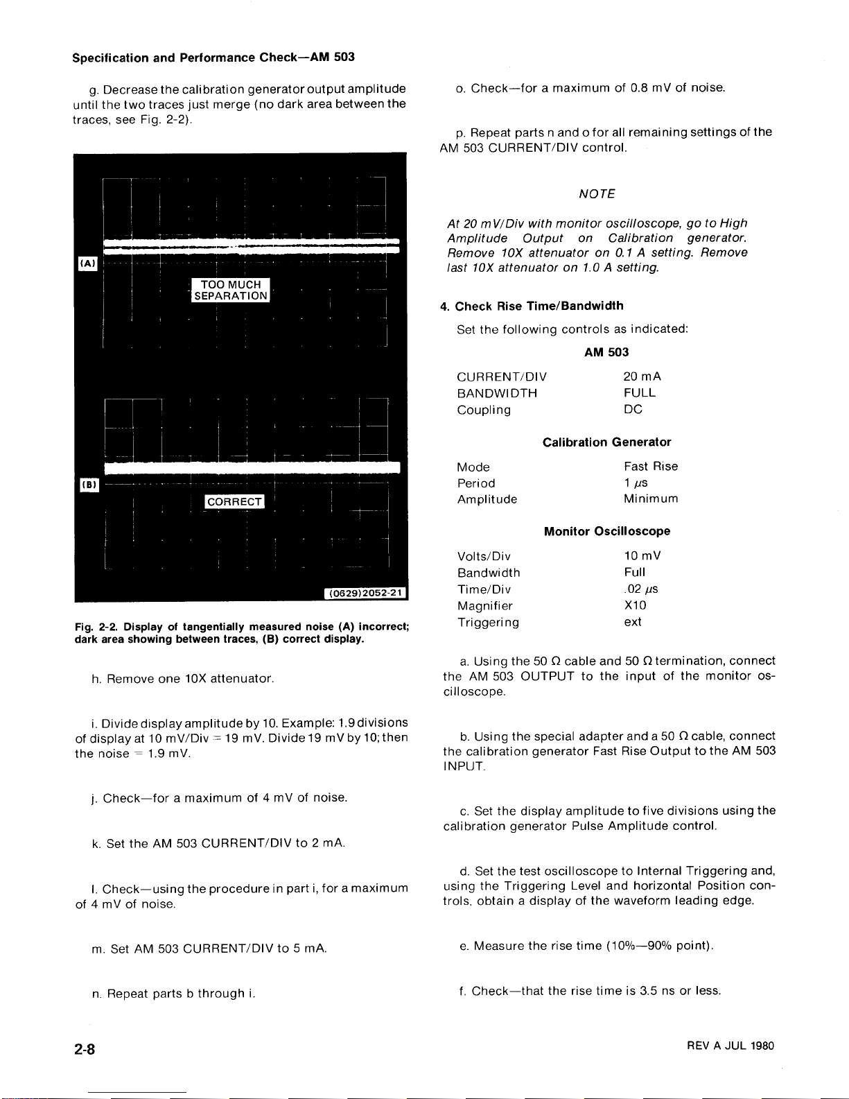
g.Decrease
the
calibration
generator
output
amplitude
until
the
two
traces
just
merge
(no
darkarea
between
the
traces,
see
Fig.2-2)
.
Fig.2-2.Display
of
tangentially
measured
noise
(A) incorrect
;
dark area
showingbetween
traces,
(B)
correct display
.
h.Remove
one10X
attenuator
.
i .
Divide
display
amplitude
by10.Example:1.9divisions
of
displayat10
mV/Div=19mV.
Divide19mVby10;then
the
noise=1.9mV
.
j
.
Check-for
a
maximum
of4mV
of
noise
.
k.Set
the
AM
503
CURRENT/DIV
to 2
mA
.
I.Check-using
the
procedure
in
parti,foramaximum
of4mV
of
noise
.
m.Set
AM
503
CURRENT/DIV
to
5mA.
n.Repeat
parts b
throughi.
o.Check-for
a
maximum
of
0.8mV
of
noise
.
p.Repeat
parts n
and
o
for
all
remaining
settings of
the
AM
503
CURRENT/DIV
control
.
NOTE
At20
mV/Div
with
monitor
oscilloscope,goto
High
Amplitude
Output
on
Calibration
generator
.
Remove
1OX
attenuator
on0.1Asetting.Remove
last
1OX
attenuator
on1.0Asetting
.
4.Check
Rise
Time/Bandwidth
Set
the following
controlsasindicated
:
AM
503
CURRENT/DIV
20
mA
BANDWIDTH
FULL
Coupling
DC
Calibration
Generator
Mode
Fast Rise
Period
1
ps
Amplitude
Minimum
Monitor
Oscilloscope
Volts/Div
10
mV
Bandwidth
Full
Time/Div
.02
ps
Magnifier
X10
Triggering
ext
a.Using
the
50S2cable
and
50
S2
termination,
connect
the
AM
503
OUTPUT
to
the
input
of
the
monitor
os-
cilloscope
.
b.Using
the
special
adapter
anda50S2cable,
connect
the
calibration
generator
Fast
Rise
Outputtothe
AM
503
INPUT
.
c.Set
the
display
amplitudetofive
divisions
using
the
calibration
generator
Pulse
Amplitude
control
.
d.Set the
test
oscilloscopetoInternal
Triggering
and,
using
the
Triggering
Level
and
horizontal
Position
con-
trols,
obtainadisplayofthe
waveform
leading
edge
.
e.Measure
the
rise
time
(10%-90%
point)
.
f.Check-that
the
rise
timeis3.5nsorless
.
REV
A JUL
1980
g.Disconnect
the
calibration
generator
from
the
special
adapter
.
least4MHz
and
not
more
than6MHz
.
h.Connect
the
sine-wave
generator
Output
to
the
q.Disconnect
the
cable
from
the
Output
of
the
sine
special
adapter
.
wave
generator
and
connecttothe
Outputofthe
function
generator
.
i .
Set
the following
controlsasindicated
:
AM
503
j
.
Adjust
the
Output
Amplitude
controlofthesine-wave
s.Set the
function
generator
Amplitude
control
for
a
generator
forasix-division
display
.
six-division
display
.
k.Increase
the
frequency
of
the
sine-wave
generator
t.Decrease
the
frequency
of
the
function
generator
until
the
displayisreduced
to 4.2divisions
.
until
the
displayisreduced
to4.2
divisions
.
I .
Check-that
the
sine-wave
generator
frequencyisat
u.Check-that
the
function
generator
frequencyisnot
least
100
MHz
.
more
than7Hz
.
REV
NOV
198
1
Specification
and
Performance
Check-AM
503
p.Check-that
the
sine-wavegenerator
frequencyisat
r.Set
the following
controlsasindicated
:
2-9
m.Change
the
following
controlsasindicated
:
AM
503
BANDWIDTH
5
MHz
Sine-Wave
Generator
5.DC
Level
Set the
following
and
Balance
controls
as
indicated
:
AM
503
Current/Div
1
mA
Frequency
Range
Ref
350
kHz
Bandwidth
Full
Coupling
Cal
DC
n.Adjust
Output
Amplitude
of
the
sine-wave
generator
forasix-division
display
.
Monitor
Oscilloscope
Volts/Div
10
mV
o.Increase
the
frequency
of
the
sine-wave
generator
Time/Div
10us
until
the
display
amplitude
is
reduced
to 4.2divisions
.
Triggering
ext
CURRENT/DIV
5
mA
AM
503
BANDWIDTH
FULL
CURRENT/DIV
20
mA
Coupling
DC
BANDWIDTH
Coupling
5
MHz
AC
Leveled
Sine-Wave
Generator
Function
Generator
Frequency
Range
(MHz)
REF
350kHz
Amplitude
Multiplier
X
.01
Frequency
1
kHz
Output
Amplitude
3
.0
Amplitude
Minimum
Monitor
Oscilloscope
MonitorOscilloscope
Volts/Div
10
mV
Volts/Div
50
mV
Time/Div
50"s
Time/Div
lops
Triggering
ext
Triggering
ext
Specification
and
Performance
Check-AM
503
a.Set
monitor
oscilloscope
input
couplingtognd
.
Position
trace
verticallyatthe
centerofthe
CRT
.
2-10
b.Reset
monitor
oscilloscope
input
coupling toDC.
NOTE
If
the
trace
has
moved
from
the
gnd
setting,
there
is
an
offset
problem
with
the
monitor
oscilloscope
.
c.Usinga50Ocable
and
a50f2
feed-through
ter-
minator,
connect
the
AM
503
OUTPUT
to
the
inputofthe
monitor
oscilloscope
.
d.Reset
the
AM
503
couplingtoDC
.
e.Adjust
the
front
panel
balance
sothereisa
minimal
shiftonmonitor
oscilloscope
trace
between
the
Cal
DC
Level
position
and
the
DC
position
on
the
AM
503
.
f.Remove
test
set-up
.
This
complete
the
performance
check
.
@
JUL
198
0

WARNING
THE
FOLLOWING
SERVICING
INSTRUCTIONS
ARE FOR
USE
BY
QUALIFIED
PERSONNEL
ONLY
.
TOAVOID
PERSONAL
INJURY,
DO
NOT
PERFORM
ANY
SERVICING
OTHER
THAN
THAT
CONTAINED
IN
OPERATING
INSTRUCTIONS
UNLESS
YOUARE
QUALIFIED
TO
DO SO
.
REFER
TO
OPERATORS
SAFETY
SUMMARY
AND
SERVICE
SAFETY
SUMMARY
PRIOR
TO
PERFORMING
ANY
SERVICE
.
Introduction
This
adjustment
procedureistobeusedtorestore
the
AM
503tooriginal
performance
specifications.Adjust-
ment
need
notbeperformed
unlessthe
instrument
failsto
meet
the
Performance
Requirements
of
the
Electrical
Characteristics
listedinthe
Specification
section,
or the
Performance
Check
cannotbecompleted
satisfactorily
.
Completion
of
all
adjustment
steps
in
this
procedure
ensures
that
the
instrument
will
meet
the
performance
requirements
listedinthe
Specification
section.However,
to
fully
ensure
satisfactory
performance,itis
recommend-
ed
that
the
Performance
Check
be
performed
after
any
adjustment
is
made
.
Adjustment
Instructions
The
alphabetical
instructions
under
each
step
(a,
b, c,
etc.)may
contain
Check,
Examine,orAdjust
as the
first
word
of
the
instruction.These
terms
are
defined
as
follows
:
1.Check-indicates
that
the
instruction
accomplishes
a
performance
requirement
check.Each
performance
requirementisderived
from
the
instrument
specification
as
listed
in
Table
2-1,
Electrical
Characteristics
.
2
.
Examine-usually
precedes
an
Adjust
instruction
and
describes
howtodetermine
whethertheadjustment
is
necessary.Measurement
limits
following
the
word
Ex-
amine
are nottobe
interpreted
as
performance
limits
derived
from
the instrument
specifications.They
are
provided
as
indicatorsofa
properly functioning
instru-
ment
andtoaidinthe
adjustment
process
.
3.Adjust-describes
which
adjustmenttousetomake
REV
A
NOV
197
9
ADJUSTMENT
Table
3-1
Adjustment
Interval
Services
Available
Test
Equipment
Required
LIST
OF
TEST
EQUIPMENTREQUIREMENTS
Section
3-AM
503
the
desired
result.We
recommend
that
adjustments
not
be
madeifa
previous
CheckorExamine
instruction
indicates
thatnoadjustmentisnecessary
.
To
maintain instrument accuracy,
check
the
perfor-
manceofthe Current
Probe
Amplifier
every
1,000
hours
of
operation,orevery
six
monthsifused
infrequently
.
Tektronix,
Inc.provides
complete
instrument
repair
and
adjustmentatlocal Field
Service
Centers
andatthe
Factory Service
Center.Contact
your
local
Tektronix
Field
Officeorrepresentative
for
further
information
.
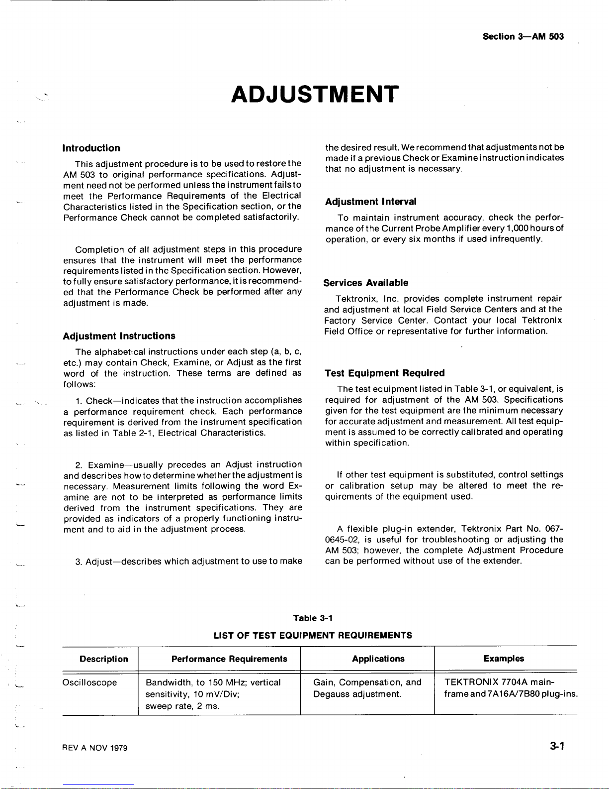
The
test
equipment
listedinTable
3-1,orequivalent,
is
required
for
adjustment
of
the
AM
503.Specifications
given
for
the
test
equipment
arethe
minimum
necessary
for
accurate
adjustment
and
measurement.All
test
equip-
mentisassumedtobe
correctly
calibrated
and
operating
within
specification
.
If
other
test
equipmentissubstituted,
control
settings
or
calibration
setup
may
be
alteredtomeet
the
re-
quirementsofthe
equipment
used
.
A
flexible
plug-in
extender,
Tektronix
Part
No
.
067-
0645-02,isuseful
for
troubleshootingoradjusting
the
AM
503;however,
the
complete
Adjustment
Procedure
canbeperformed
without
useofthe extender
.
Description
Performance
Requirements
Applications
Examples
Oscilloscope
Bandwidth,to150
MHz;vertical
Gain,
Compensation,
and
TEKTRONIX
7704A
main-
sensitivity,10mV/Div
;
Degauss
adjustment
.
frame
and7A16A/7B80plug-ins
.
sweep
rate,2ms
.
Adjustment-AM
503
Preparation
3-
2
a
RequiresTM500-Series
Power
Module
.
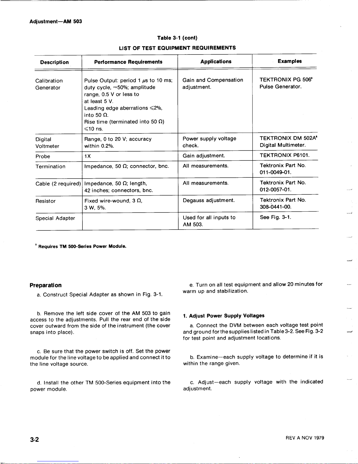
a.Construct
Special
AdapterasshowninFig.3-1
.
b.Remove
the
left
side
cover
of
the
AM
503
to
gain
access
to
the
adjustments.Pull
the
rear
endofthe
side
cover
outward
from
the
sideofthe instrument
(the
cover
snaps
into
place)
.
c.Be
sure
that
the
power
switchisoff.Set the
power
module
for
the
line
voltagetobe
applied
and
connectitto
the
line
voltage
source
.
d.Install
the
otherTM500-Series
equipment
into
the
power
module
.
Table
3-1 (cont)
LIST
OFTEST
EQUIPMENTREQUIREMENTS
e.Turnon
all
test
equipment
and
allow 20
minutes
for
warm
up
and
stabilization
.
1.Adjust
Power
Supply
Voltages
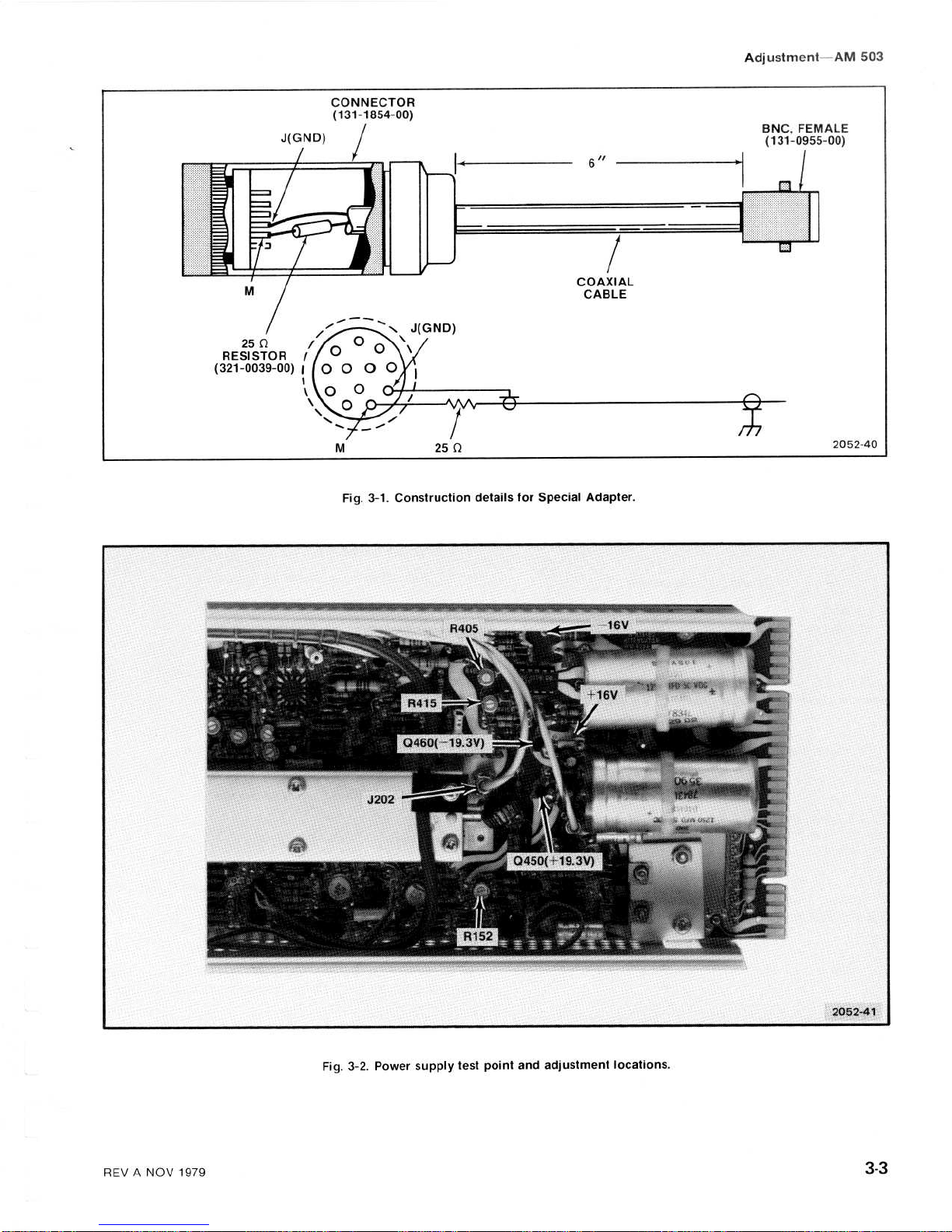
a.Connect
the
DVM
between
each
voltage
test
point
and
ground
forthesupplies
listedinTable3-2.See
Fig.3-2
for
test
point
and
adjustment
locations
.
b
.
Examine-each
supply voltagetodetermine
ifitis
within
the
range
given
.
c
.
Adjust-each
supply
voltage
with
the
indicated
adjustment
.
REVANOV
1979
Description
Performance
Requirements
Applications
Examples
Calibration
Pulse
Output:period1us
to
10ms;
Gain
and
Compensation
TEKTRONIX
PG
506'
Generator
duty
cycle,
~50%
;
amplitude
adjustment
.
Pulse
Generator
.
range,0.5Vor less to
at
least5V
.
Leading
edge
aberrations
<2%,
into500
.
Rise time
(terminated
into
50 0)
<10ns.
Digital
Range,
0 to 20V;
accuracy
Power
supply
voltage
TEKTRONIX
DM
5029
Voltmeter
within0.2%
.
check
.
Digital
Multimeter
.
Probe
1X
Gain
adjustment
.
TEKTRONIX
P6101
.
Termination
Impedance,
500;
connector,
bnc
.
All
measurements
.
Tektronix
PartNo.
011-0049-01
.
Cable(2required)
Impedance,
50S2;
length,
All
measurements
.
Tektronix
PartNo.
42 inches;connectors,
bnc
.
012-0057-01
.
Resistor
Fixed
wire-wound,3S2,
Degauss
adjustment
.
Tektronix
PartNo.
3W,5%
.
308-0441-00
.
Special
Adapter
Used
for
all
inputs
to
See
Fig.3-1
.
AM
503
.
J(GND)
250
RESISTOR
/
(321-0039-00)
f
I
w
CONNECTOR
(131-1854-00)
COAXIAL
CABLE
BNC,
FEMALE
(131-0955-00)
2052-40
Fig.3-1.Construction
details
for
Special
Adapter
.
Fig.3-2.Power
supply
test
point
and
adjustment
locations
.
Adjustment-AM
503
REVANOV
1979
3-3
 Loading...