

Page 1

AIM7
Thermocouple Input Module
The AIM7 Thermocouple Input Module accepts signals
from thermocouple tyies J, K, S, T, B, E, and Rior generic
voltages up to L-1OOmV full scale. The AIM7 offers 16
channels of differential input, as well as guard and ground
screw terminals.
The AIM7 provides channel selection through on-card
multiplexing. Gain is fixed at 100 volts/volt. On-card cold
junction reference circuitry provides an accurate tempera-
fi~r~r~f~r~n~~fnrfharmnrnr~nlnrnnac~~rnrnnntc
C-L A/_ljbAbLLx.L AVIL
Signals from the ATM7 are routed along the AN OUT signal
path to the system global amplifier and A/D converter
where programmable gain can be applied before A/D
conversion.
All thermocouple inputs are applied to screw terminals
located on an isothermal block to minimize errors caused
by temperature differences between the input connectors
and the reference junction sensor. The cold junction reference sensor itself is mounted in the isothermal block to
accurately measure the temperature of the block. In addition, a driven guard connection has been provided for the
connection of signal shields. Guarding can minimize the
noise picked up by signal input lines.
L.L&UAAL"~"Ly/
IL A&LLUUuAL~1LA.W.
The AIM7 may be placed in slots Z-10 of the system
baseboard. However, to
and noise effects, the ATM7 should be placed in the lowest
numbered available slot. To install the AlM7 in a Model
5OOA, 5OOP, or 556, remove the baseboard top cover and
place the module in the desired slot with the component
side facing the power supply. For the Model 570 or 575,
open the system clamshell cover and place the module in
the system option slot with the components facing upward.
Always turn off the data acquisition system
power supply before installing or removing
modules. Always operate the system with the
top cover in place to minimize the possibility
of EM1 radiation.
minimize power supply thermal
CAUTION
User Configured Components
The signal input screw terminals located on the isothermal
block are the only user-configured components on the
AIM7 module. For the location of these terminals, refer to
Figure 1. Note that the terminals provide connections for
the 16 input channels as well as separate connections for
ground and guard.
Document Number: 500-917-01 Rev. D
AlM7-1
Page 2

TJaermocouple Input Module
,Q@
-- ------ ---------__
PI74
‘igure 1. AIM7 Module Configurafion
Connecting Terminals
The AlM7 accepts up to 16 differential input channels.
These channels are marked channel 0 through channel 15.
Each channel has two input terminals labeled (+> and (-1 for
positive and negative inputs, respectively. Note that you
must observe proper polarity when connecting thermocouples to the AlM7 module. The positive thermocouple
wire must
be connected to the (+> terminal, and the negative thermocouple wire must be connected to the (-1 terminal. The negative TC wire is usually red. Typical connections for channel 0 are shown in Figure 2. In this example,
the shield is connected to the guard terminal; guarded connections are discussed in the following section.
Color coding of thermocouple wires varies according to
type. Table 1 gives the ANSI color codes for the various
thermocouple types supported by the Module. When
adding extension cable, use only the specific type of cable
recommended for the thermocouple being used.
Table 1. Thermocouple Color Codes
Type Material
B
Platinum 30% rhodium
(+) Wire
Gray
Platinum 6% rhodium
;
K
R
Chromel-constantan
Iron-constantan
Chrome&alumel
Platinum 13% rhodium
Purple
White
Yellow
Black
Pure platinum
S
Platinum 10% rhodium
Black
Pure platinum
r
Copper-con&man
Blue
CAUTION
Maximum input voltage is 215V (power on),
or HOV (power off). Exceeding these values
may damage the module. If any input exceeds
klOV (power on), measurement error is likely
to occur.
t-1 Wire
Red
Red
Red
Red
Red
Red
Red
AlM7-2
Page 3

Thermocouple Input Module
Guarding
On long signal runs, or in electrically noisy environments,
use shielded cable to reduce noise pickup. If your temperature reading is unstable, noise induced into the thermocouple wire may be the problem.
When using shielded thermocouples with the AlM7, the
shield should be connected to one of the AIM7 guard
terminals rather than moduleground or baseboard ground.
These terminals are actively driven by an on-card buffer
amplifier, so that GUARD is maintained at the common
mode voltage of the input signal.
If the shield is connected in this manner, it should not be
connected to the thermocouple signal wires or to ground at
any point. Doing so will short-circuit the output of the
guard amplifier, possibly damaging the AIh47.
For guarding to be effective, the same shield must carry
both the positive and negative leads of the thermocouple
signal, and no other signal lines. Each input line should
have its own shield, and all shields should be connected to
one of the GUARD terminals. Figure 2 shows typical
guarded connections. Note that the shield is connected to
GUARD, while the thermocouple signal lines are con-
netted to the (+) and (-) terminals of channel 0.
Connecting Thermocouples
A thermocouple is a sensor made by joining two dissimilar
metals for the purpose of temperature measurement. When
dissimilar metals are joined in a closed circuit, and the two
junctions are held at different temperatures, a small electric
current will flow through the circuit. The voltage generated under such conditions will depend on the temperature difference between the two junctions as well as the
types of metals being used.
When thermocouples are used for temperature measurement, one junction is kept at a known reference temperature (often the melting point of ice: O’C). Tables and curves
that describe the relationship of thermocouple voltage to
temperatures assume that the temperature of the reference
junction is 0°C.
If the temperature of the reference junction is known
precisely, however, it is not necessary that it be maintained
at 0°C. The same tables and curves will be accurate if
compensation is made for the temperature of the reference
junction. Such compensation is often referred to as “cold
junction compensation”, and is achieved by adding to the
voltage of the thermocouple the voltage which would be
produced by measuring the temperature of the reference
&
j;nction. *
Ii
+5-
$gue 2. Typical AIM7 Connections (Channel 0, Guarded Connections shown)
THERMOCOUPLE
JUNCTION
Page 4

Thermocouple Input Module
For example, if the reference junction is at 25”C, and the
measuring junction is at 75”C, then the thermocouple will
measure a difference of 50’Crather than the expected 76°C.
Therefore, the output of the thermocouple will be smaller
than expected. Adding the voltage equivalent of a 25°C
difference willcompensate for the fact that the reference
junction is not actually at 0°C.
Cold junction reference circuitry located on the AIM7
measures the temperature of the reference junction at the
screw terminals. Because of the isothermal block, thermal
offsets between the measurement point and the terminals
are kept to a minimum. When the SELECT CHANNEL
command is performed with a value of 32, the voltage
output of the compensation circuitry can be read by the
A/D converter. Channel 32 (cold junction reference) will
read lOOmV/‘C. At O’C this channel will read OV, and at
5o”c, 5v.
Because the temperature/voltage relationship of the refer-
ence sensor is linear, the voltage produced by the compensation circuitry easily converts to temperature in software.
To find the appropriate conversion voltage, consult the
tables for the particular type of thermocouple being used.
Find the voltage produced by that type of thermocouple at
the temperature of the reference junction, and then add the
correction voltage to the reading from the thermocouple
itself.
In the previous example, consult the table to determine the
compensation voltage at 25°C. If the thermocouple were
typeT (Copper/Cons&&an), the voltage at 25°C would be
0.992mV- Add this voltage (in software) to the actual
voltage output of the thermocouple.
This can be done by using a polynomial equation describ.
ing the specific voltage/temperature relationship for the
thermocouple in question, by looking up the correct value
in a table, or by using piecewise linear approximations.
Keithley’s various software packages perform voltage-to-
temperature conversion and linearization automatically.
The AIM7 is factory configured to provide a gain of 100
volts/volts on each of the 16 input channels. This gain
value is suitable for using thermocouple types B, E, J, K, R,
S, and T.
When an appropriate gain is applied via the PGA on the
A/D module, the A/D converter can achieve an average
resolution of l°C or better across the useful range of the
thermocouple. Table 2 indicates the average temperature
increments represented by each digital step for a 12-bit and
16-bit modules. In either case, these figures will give a good
indication of the resolution to expect when measuring the
full temperature range of the ALMY.
Resolution can be increased with any of the following
modifications:
1. usingathermocouplewithasmallertemperafurerange,
and increasing the PGA gain,
2. setting the A/D converter to a smaller input range (for
example, 0 to 1OV when temperatures below 0°C will
not be measured), or
3. by using a 16-bit A/D module instead of a 12-bit A/D
module. This will increase resolution by a factor of 16.
Unfortunately, the voltage output of thermocouples is
non-linear with respect to temperature. When using the
AIM7 module, linearization and the conversion of the
voltage into temperature must be carried out in software.
AlM7-4
Table 3 gives temperature ranges and output voltages for
the thermocouple types supported by the AIM7 module.
For all those listed, better than 1°C resolution can be
expected as long as a suitable PGA gain is used (see Table
2).
Page 5

Thermocouple Input Module
Table 2. Average Temperature Value of Conversion Step with A/D Converter (Resolution)
TC+
TYPe
B (85OC)
J
(3500
K (6OOC)
R (85OC) o-1ov x5 xl00
S (85OC) o-1ov x5
r (ZOOC)
NOTES:
1.
Temperature shown is a value mid-way between the minimum and maximum useable range for the thermocouple.
2.
Calculations made at indicated temperature. Resolution may vary at higher and lower temperatures.
3.
Where calculations are made only for 0-1OV A/D range, thermocouple does not support readings below zero C.
4.
Resolution is maximum theoretical resolution. Accuracy and resolution will be affected by noise and the accuracy of conversion algorithms.
Range Gain Gain Input
0-1OV 1 x5 ( xl00 1 0-20mV
I
o-1ov x2
o-1ov x2 xl00 0-50mV
sov
o-1ov x5 xl00
IklOV x5
PGA AIM7 AIM7 F.S.
xl00 0-50mV
x2 xl00 k5OmV
0-20mV
xl00 0-20mV
0-20mV
xl00
SO-mV
X2-bit AiD Resolution
Volts Temp. Volts Temp.
4.88pV 0.61C deg
24.4pV
48.8pV
12.2pv
12.2pv
24.4pV
4.88pV
4.88pV
4.88pV
9.76pV
0.3OC deg
0.6OC deg
0.22C deg
0.29C deg
0.58C deg
0.38C deg
0.4OC deg
0.09C deg
0.18C deg
16-bit A/D Resolution
0.305j.Lv 0.038C deg
I
1.526/.1.V
3.052/,~V 0.038C deg
0.763pV 0.014C deg
0.763j~V 0.018C deg
1.526p-v 0.036C deg
0.305j.lv 0.023C deg
0.305!.l.v 0.025C deg
0.305pv 0.006C deg
0.61OpV
0.019C deg
0.012C deg
I
‘We I
B
E
J
K
R
S
T
Table 3. Useful Temperature Ranges and Associated Voltages
Material
Platinum 30% Rhodium
Platinum 6% Rhodium
Chromel-constantan
Iron-constantan
Chromel-alumel
Platinum 13% Rhodium
Pure Platinum
Platinum 10% Rhodium
Pure Platinum
Copper-constantan
Range CC)
I
0 to 1700
-200 to 900
0 to 750
-200 to 1232
0 to 1450
0 to 1450
-200 to 350
Range tern0
I
O.OOmV to 12.426mV
-8.824 to 68.783mV
O.OOmV to 42283mV
-5.973 to 49.988mV
O.OOmV to 16.741mV
O.OOmV to 14.973mV
-5.602 to 17.816mV
AlM7-5
Page 6
Thermocouple Input Module
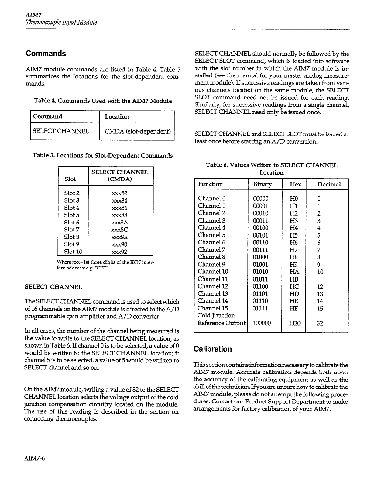
Commands
AIM7 module commands are listed in Table 4. Table 5
summarizes the locations for the slot-dependent commands.
Table 4. Commands Used with the AIM7 Module
Command
I
SELECT CHANNEL
I
Table 5. Locations fox Slot-Dependent Commands
Slot
I I
Slot 2
Slot 3
Slot 4
Slot 5
Slot 6
Slot 7
Slot 8
Slot 9
Slot 10
Where xxx=lst three digits of the IBIN interface address; e.g. “CFF’.
SELECT CHANNEL
The SELECT
of 16 channels on the AM7 module is directed to the A/D
programmable gain amplifier and A/D converter.
In all cases, the number of the channel being measured is
the value to write to the SELECT
shown in Table 6. If channel 0 is to be selected, a value of 0
would be written to the SELECT
channel 5 is to be selected, a value of 5 would be written to
SELECT channel and so on.
On the AIM7 module, writing a value of 32 to the SELECT
CHANNEL location selects the voltage output of the cold
junction compensation circuitry located on the module.
The use of this reading is described in the section on
connecting thermocouples.
CHANNEL command is used to select which
Location
CMDA (slot-dependent)
SELECT CHANNEL
(CMDA)
xxx82
xxx84
xxx86
xxx88
xxx8A
XXXK
xxx8E
xxx90
xxx92
CHANNEL location, as
CHANNEL location; if
I
SELECT CHANNEL should normally be followed by the
SELECT SLOT command, which is loaded into software
with the slot number in which the AIM7 module is installed (see the manual for your master analog measurement module). If successive readings are taken from various channels located on the same module, the SELECT
SLOT command need not be issued for each reading.
Similarly, for successive readings from a single channel,
SELECT CHANNEL need only be issued once.
SELECT CHANNE
least once before starting an A/D conversion.
Table 6. Values Written to SELECT CHANNEL
Function
Channel 0
Channel 1
Channel 2
Channel 3
Channel 4
Channel 5
Channel 6
Channel 7
Channel 8
Channel 9
Channel 10
Channel 11
Channel 12
Channel 13
Channel 14
Channel 15
Cold Junction
Reference Output
L and SELECT SLOT must be issued at
Location
Binary
00000
00001
00010
00011
00100
00101
00110
00111
01000
01001
01010
01011
01100
01101
01110
01111
100000
Hex Decimal
HO
Hl
H.2
H3
H4
H5
H6
H7
H8
H9
HB
HC
I-ID
HE
HI!
I320
0
1
2
3
4
5
6
7
8
9
10
12
13
14
15
32
Calibration
This section contains information necessary to calibrate the
AIM7 module. Accurate calibration depends both upon
the accuracy of the calibrating equipment as well as the
skill of the technician. If you are unsure how to calibrate the
AIM7 module, please do not attempt the following procedures. Contact our Product Support Department to make
arrangements for factory calibration of your AlM7.
AlM7-6
Page 7
Thermocouple Input Module
Environment Conditions
Calibration of the AIM7module should be performed at an
ambient temperature of 23°C zk5”C. Turn on the system
power with the AIM7 module installed and allow it to
warm up for at least 10 minutes before beginning the
calibration procedure.
Recommended Calibration Equipment
Use the equipment below to calibrate the AIM7 module.
Other equipment may be substituted as long as relevant
specifications are at least as good as these given below:
1. Digital Voltmeter (kO.OlS% basic DC accuracy)
2. DC Millivolt Reference Source (zkO.O5% accuracy).
3. Digital Thermometer (zkO.3”C accuracy).
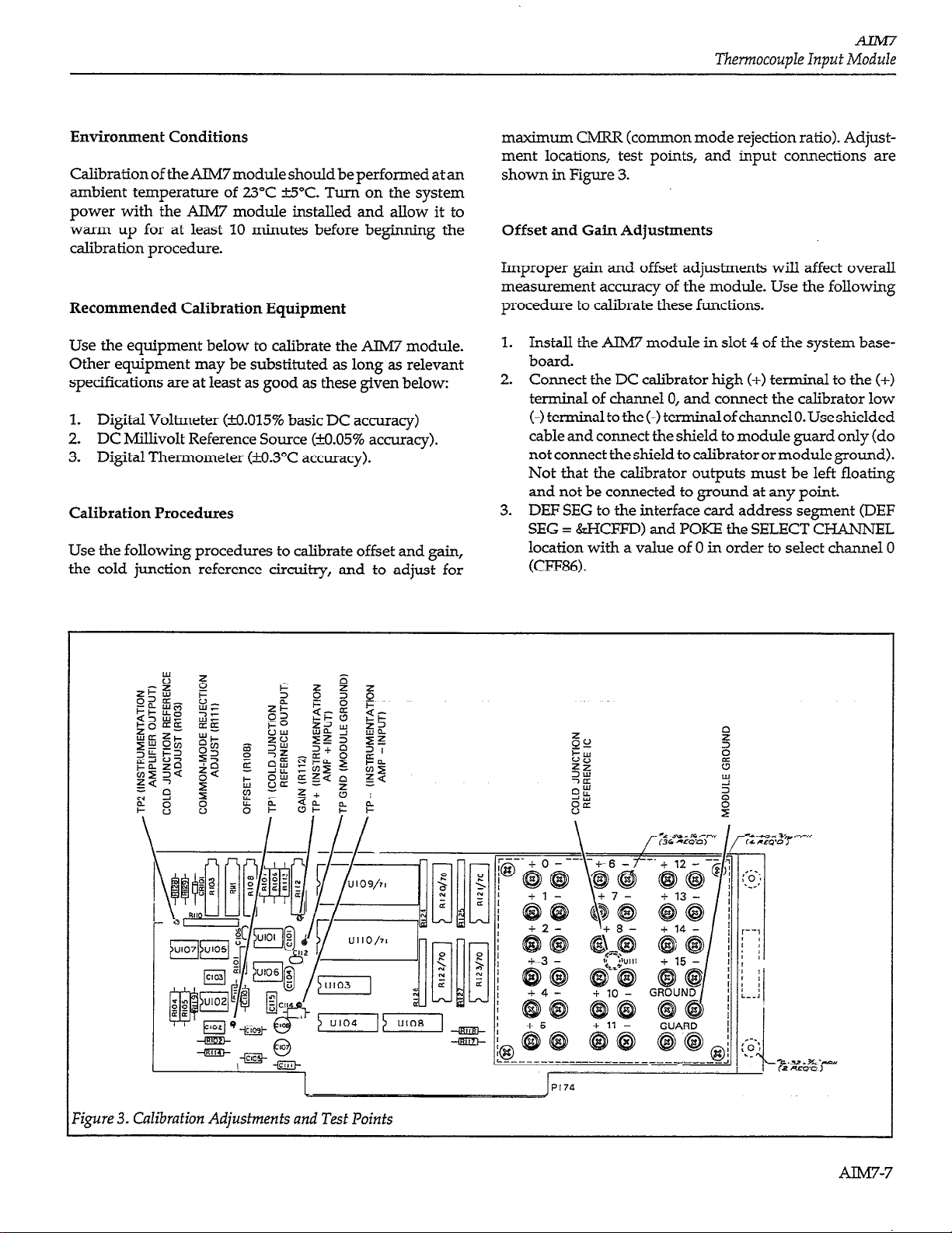
Calibration Procedures
Use the following procedures to calibrate offset and gain,
the cold junction reference circuitry, and to adjust for
maximum CMRR (common mode rejection ratio). Adjustment locations, test points, and input connections are
shown in Figure 3.
Offset and Gain Adjustments
Improper gain and offset adjustments will affect overall
measurement accuracy of the module. Use the following
procedure to calibrate these functions.
1. Install the AIM7 module in slot 4 of the system baseboard.
2. Connect the DC calibrator high (+> terminal to the (+>
terminal of channel 0, and connect the calibrator low
(-1 terminal to the (-) terminal of channel 0. Use shielded
cable and connect the shield to module guard only (do
not connect the shield to calibrator or module ground).
Not that the calibrator outputs must be left floating
and not be connected to ground at any point.
3. DEF SEG to the interface card address segment (DEF
SEG = &HCFFD) and POKE the SELECT CHANNEL
location with a value of 0 in order to select channel 0
(CFF86).
7gure 3. Calibrafion Adjusfmenfs and Tesf Points
Page 8

Thermocouple Input Module
4. Connect the DMM high input lead to TP2 of the AIM7.
Connect the DMM low terminal to TP GND. Select the
DCV function and place the DMM in the autorange
mode.
5. Set the DC calibrator output voltage to exactly OV.
6. Adjust the offset control (R108) for a reading of OV
*lmV on the DMM.
7. Move the DMM high input lead to Tl?2 of the AIM7.
8. Set the calibrator voltage to exactly lOO.OOmV.
9. Set the gain adjustment (R112) for a reading of lO.OOOV
+lmV on the DMM.
10. Repeatsteps4through9untilnofurtherchangeisseen
in the off-set readings.
Cold Junction Reference Adjustment 2.
The cold junction reference adjustment supplies a voltage
of 100mV/°C that is used by the software to calculate the
final reading. As with the offset and gain adjustments,
incorrect calibration of the cold junction reference circuitry
will affect measurement accuracy. Use the following procedure to calibrate the cold junction reference. The procedure assumes that the module is still installed in slot 4 of
the system baseboard.
1.
Connect the DMM high input lead to Tl?l of the AIM7
module. Connect the DMMlowlead tomoduleground.
Set the DMM to measure DCV in the autoranging
mode.
2.
Apply thermal grease to the tip of the measurement 6.
probe. 7.
3.
Remove the four screws that secure the isothermal
block insulator and remove the insulator (the block
itself is secured by screws on the backside of the circuit
board and should not be removed).
4.
Locate the cold junction reference sensor IC (Ulll) at
the center of the isothermal block. Touch the temperature probe tip to the case of this IC and allow five
minutes for the reading to stabilize.
5.
Adjust the cold junction reference control (R103) for a
reading of 1OOmV x T”C on the DMM. For example, at
23’C, adjust for a reading of 2.3V.
6.
Replace the isothermal block insulator and secure it
with the four screws removed earlier.
module is below par. Symptoms of lower than normal
CMRR may show up as noisier than usual temperature
readings, depending in the type of noise, and the way the
noise is being introduced into the thermocouple signal.
Note that the offset and gain controls will require re-
adjustment if the CMRR adjustment is made.
Proceed as follows (assumes the use of BASIC):
1.
3.
4.
5.
8.
9.
Theory of Operation
A schematic diagram of the AIM7 module may be found on
drawing number 500426, located at the end of this supplement.
Connect the DMM high input lead to Tl?2 of the AlM7.
Connect DMM low to module ground. Place the DMM
in DCV and select autoranging.
Connect a jumper wire between the (+> and (-1 terminals of channel 0. Connect the high lead of the DC
calibrator to these two terminals, and connect the low
signal lead of the calibrator to module ground.
Issue a DEF SEG command to change to the segment
address of the IBIN interface. For example, if the IBIN
is addressed at CFW30, issue the command ‘DEF SEG
= &HCFF.Y. POKE the SELECT CHANNEL location
with a value of 0 in order to select channel 0 (Address
xXx86).
Set the DC calibrator output for a value of exactly
1o.oOOv.
Adjust the common-mode rejection control (Rlll) for
a reading as close to OV as possible, as seen on the
Dh4M.
Set the calibrator output to a value of exactly -lO.OOOV.
Adjust RI 11 again for a reading as close as possible to
ov.
Repeat steps 4-7 until a minimum change is seen in the
output when going from +lOV to -lOV inputs.
Disconnect the DC calibrator and remove the jumper
wire connected between the (+> and (-1 terminals of
channel 0.
Common-Model Rejection Adjustment
The common-mode rejection adjustment should not normally be required in the field; however, the following
procedures may be used if the common-mode rejection
adjustmentpotentiometerhasbeenadjustedinadvertently,
or in cases where it is suspected that the CMRR of the
AIW-8
Thermocoupleinputsignals are applied to screw terminals
located on the isothermal block This block is used to
minimize thermal offsets that would otherwise decrease
temperature accuracy. The (-1 terminals of the input chan-
nels are connected to ground through 1MQ resistors, R120-
123. These resistors are used to prevent the output of themsinunentation amplifier from saturation due to the effects
Page 9

Thermocouple Inpu f Module
of stray capacitance and offset current at the input.
From the input terminals, signals are applied to two analog
multiplexers, UlO9 and UllO. The muliiplexers are driven
by U104, a quad transparent latch (74LS75), which stores
the status of the FO-F3 data lines. The enable lines are
driven by U108, also a quad transparent latch (74LS751,
which stores data
from
F5. Data lines FO-F3 and F5, and
thus these two latches, are controlled by writing the appropriate value (O-15, or 32) to the SELECT CHANNEL location (signal line CMDA).
TheoutputsofthemuItiplexers,U109andU110,arerouted
to the inputs of the instrumentation amplifier, which is
made up of ICs UlOl, U106, and U107. Gain for the instrumentation amplifier is set to xl00 volts/volt by resistors
R106, R107, and R113, along with potentiometer R112,
which provides the gain trim for the module. R108 pro-
vides the offset trim adjustment, while Rlll gives a means
to maximize common-mode rejection. The output of the
instrumentation amplifier is filtered by R119 and C115,
which make up a single-pole low-pass filter.
After filtering, the output of the instrumentation amplifier
is directed to oneinput of UlO3, a one-of-two analog switch
(ADG200). The second input of U103 is connected to the
output of the cold junction reference circuitry made up of
U102 and Ulll. The output of U103 drives the AN OUT
pathway exiting the module. U103 is controlled by the
output of one latch in U108, which stores the status of data
line F5.
The 1OV reference bus
from
the baseboard, buffered by
voltage follower UlO2A, drives amplifier U102B configured with Ulll. Ulll is a precision semiconductor temperature sensor with an output set to l@ per degree
centigrade. Ulll is physically mounted at the center of the
isothermal block to
minimize thermal offsets. The current
output of Ulll is converted into a lOOmV/‘C voltage by
U102B, such that at 0°C the output is OV, and at 50°C the
output is 5V. Calibration of the cold junction reference
circuitry is performed by adjusting R103.
The GUARD terminals of the AIM7 are actively driven at
the common-mode voltage of the selected thermocouple
signal by U105, an operational amplifier configured as a
voltage follower. This op amp has the low output impedance necessary to drive the guard output of the module.
Table 7. AIM7 Troubleshooting
Step Item/Component Required Condition Remarks
1
2
Chassis to baseboard chassis.
COMect
DMM high U109, +15v, zkO.lV +15v supply
Connect DMM high unless otherwise noted. Leave connected
pin 1.
3
Connect DMM high U109,
-15v, &O-IV -15V supply
pm 27.
4
COMect
DMM high to UlO2A, +lOV, k0.05V 1OV referenced
u102A, pin 3.
5 DMM high COMect to TIP2
6 Voltage source Connect to + and - terminals of channel 0 Apply test signal
7
Computer
Select channel 0 on card Use POKE
statements
8 Voltage Source Set to OV
9 DMIVI
OV *lmV
10 Voltage source Set to 1OOmV
11 DMM
12
13 DMM high
14 DMM
1OV zklmV 1OOmV in 1OV out
Repeat steps 6-11 for channels l-15
COMKt t0 ?-??I
1OOmV x T”C
Check all multiplexer inputs
Cold junction reference
Measure Ul 10 temperature
with thermometer
AIM7-9
Page 10

Thermocouple Input Module
Troubleshooting Information
Troubleshoot the AIM7module using the procedure listed
in Table 7. Parts may be obtained from Keithley Data Acquisition and Control or the module may be returned to
Keithley Data Acquisition and Control for repair. See the
replaceable parts section of this manual for details. Note
that part numbers are listed on the component layout
drawing.
AIM7 Specifications
Input channels: 16 differential inputs
Input characteristkzl
Range: -ClOOmV, xl00 gain
Protection:
kl5V max (powered)
+lOV max (unpowered)
Accuracy: -+-(0.01% + lOllv>
Non-linearity: 0.005% of F.S.
Common mode
rejection ratio
>90dB, DC to 6OHz
Bandwidth: 1kHz
Settling time: 2msec to 0.01%
Offset TC: 21,1V/“C max
Voltage noise:
1pV p-p max, 0.1 to 1OHz
2pV p-p max, 1OHz to 1kHz
Temperature Measurement Characteristics:
Reference Junction Sensor:
Output: +lOOmV/°C
Accuracy: kO.25’C
Offset from sensor to any terminal: rto.25”C max
Offset between any adjacent terminals: kO.l”C max
System Resolution: 2
PGA = 2, ADMl on 0 to 1OV range: 12u.V/count, 0.3”C/
count
PGA = 2, ADM2 on 0 to 1OVrange: 3pV/count, O.O75”C/
count
PGA = 10, AMD2 on - to +5V range: O.bpV/count,
O.Ol5”C/coLmt
1 All amplifier specifications with respect to input.
’ Typical resolution,
(assume 40pV/T).
using
J,
K, or T thermocouple, 0 to -1400°C span
AIM7-10
Page 11

,
~r=--‘----T
._I
___-------------_--------.
)
?-------------- _----- @
L-----_--:
,$
Page 12

 Loading...